JP5449062B2 - Seal air supply device for exhaust gas turbocharger - Google Patents
Seal air supply device for exhaust gas turbocharger Download PDFInfo
- Publication number
- JP5449062B2 JP5449062B2 JP2010152374A JP2010152374A JP5449062B2 JP 5449062 B2 JP5449062 B2 JP 5449062B2 JP 2010152374 A JP2010152374 A JP 2010152374A JP 2010152374 A JP2010152374 A JP 2010152374A JP 5449062 B2 JP5449062 B2 JP 5449062B2
- Authority
- JP
- Japan
- Prior art keywords
- air
- exhaust gas
- seal air
- gas turbine
- seal
- Prior art date
- Legal status (The legal status is an assumption and is not a legal conclusion. Google has not performed a legal analysis and makes no representation as to the accuracy of the status listed.)
- Expired - Fee Related
Links
Images


Classifications
-
- F—MECHANICAL ENGINEERING; LIGHTING; HEATING; WEAPONS; BLASTING
- F04—POSITIVE - DISPLACEMENT MACHINES FOR LIQUIDS; PUMPS FOR LIQUIDS OR ELASTIC FLUIDS
- F04D—NON-POSITIVE-DISPLACEMENT PUMPS
- F04D29/00—Details, component parts, or accessories
-
- F—MECHANICAL ENGINEERING; LIGHTING; HEATING; WEAPONS; BLASTING
- F01—MACHINES OR ENGINES IN GENERAL; ENGINE PLANTS IN GENERAL; STEAM ENGINES
- F01D—NON-POSITIVE DISPLACEMENT MACHINES OR ENGINES, e.g. STEAM TURBINES
- F01D11/00—Preventing or minimising internal leakage of working-fluid, e.g. between stages
- F01D11/02—Preventing or minimising internal leakage of working-fluid, e.g. between stages by non-contact sealings, e.g. of labyrinth type
- F01D11/04—Preventing or minimising internal leakage of working-fluid, e.g. between stages by non-contact sealings, e.g. of labyrinth type using sealing fluid, e.g. steam
-
- F—MECHANICAL ENGINEERING; LIGHTING; HEATING; WEAPONS; BLASTING
- F02—COMBUSTION ENGINES; HOT-GAS OR COMBUSTION-PRODUCT ENGINE PLANTS
- F02M—SUPPLYING COMBUSTION ENGINES IN GENERAL WITH COMBUSTIBLE MIXTURES OR CONSTITUENTS THEREOF
- F02M21/00—Apparatus for supplying engines with non-liquid fuels, e.g. gaseous fuels stored in liquid form
- F02M21/02—Apparatus for supplying engines with non-liquid fuels, e.g. gaseous fuels stored in liquid form for gaseous fuels
-
- F—MECHANICAL ENGINEERING; LIGHTING; HEATING; WEAPONS; BLASTING
- F02—COMBUSTION ENGINES; HOT-GAS OR COMBUSTION-PRODUCT ENGINE PLANTS
- F02B—INTERNAL-COMBUSTION PISTON ENGINES; COMBUSTION ENGINES IN GENERAL
- F02B37/00—Engines characterised by provision of pumps driven at least for part of the time by exhaust
- F02B37/001—Engines characterised by provision of pumps driven at least for part of the time by exhaust using exhaust drives arranged in parallel
-
- F—MECHANICAL ENGINEERING; LIGHTING; HEATING; WEAPONS; BLASTING
- F02—COMBUSTION ENGINES; HOT-GAS OR COMBUSTION-PRODUCT ENGINE PLANTS
- F02B—INTERNAL-COMBUSTION PISTON ENGINES; COMBUSTION ENGINES IN GENERAL
- F02B37/00—Engines characterised by provision of pumps driven at least for part of the time by exhaust
- F02B37/007—Engines characterised by provision of pumps driven at least for part of the time by exhaust with exhaust-driven pumps arranged in parallel, e.g. at least one pump supplying alternatively
-
- F—MECHANICAL ENGINEERING; LIGHTING; HEATING; WEAPONS; BLASTING
- F02—COMBUSTION ENGINES; HOT-GAS OR COMBUSTION-PRODUCT ENGINE PLANTS
- F02B—INTERNAL-COMBUSTION PISTON ENGINES; COMBUSTION ENGINES IN GENERAL
- F02B37/00—Engines characterised by provision of pumps driven at least for part of the time by exhaust
- F02B37/12—Control of the pumps
- F02B37/16—Control of the pumps by bypassing charging air
-
- F—MECHANICAL ENGINEERING; LIGHTING; HEATING; WEAPONS; BLASTING
- F02—COMBUSTION ENGINES; HOT-GAS OR COMBUSTION-PRODUCT ENGINE PLANTS
- F02B—INTERNAL-COMBUSTION PISTON ENGINES; COMBUSTION ENGINES IN GENERAL
- F02B39/00—Component parts, details, or accessories relating to, driven charging or scavenging pumps, not provided for in groups F02B33/00 - F02B37/00
- F02B39/16—Other safety measures for, or other control of, pumps
-
- F—MECHANICAL ENGINEERING; LIGHTING; HEATING; WEAPONS; BLASTING
- F02—COMBUSTION ENGINES; HOT-GAS OR COMBUSTION-PRODUCT ENGINE PLANTS
- F02C—GAS-TURBINE PLANTS; AIR INTAKES FOR JET-PROPULSION PLANTS; CONTROLLING FUEL SUPPLY IN AIR-BREATHING JET-PROPULSION PLANTS
- F02C6/00—Plural gas-turbine plants; Combinations of gas-turbine plants with other apparatus; Adaptations of gas- turbine plants for special use
- F02C6/04—Gas-turbine plants providing heated or pressurised working fluid for other apparatus, e.g. without mechanical power output
- F02C6/10—Gas-turbine plants providing heated or pressurised working fluid for other apparatus, e.g. without mechanical power output supplying working fluid to a user, e.g. a chemical process, which returns working fluid to a turbine of the plant
- F02C6/12—Turbochargers, i.e. plants for augmenting mechanical power output of internal-combustion piston engines by increase of charge pressure
-
- F—MECHANICAL ENGINEERING; LIGHTING; HEATING; WEAPONS; BLASTING
- F02—COMBUSTION ENGINES; HOT-GAS OR COMBUSTION-PRODUCT ENGINE PLANTS
- F02C—GAS-TURBINE PLANTS; AIR INTAKES FOR JET-PROPULSION PLANTS; CONTROLLING FUEL SUPPLY IN AIR-BREATHING JET-PROPULSION PLANTS
- F02C7/00—Features, components parts, details or accessories, not provided for in, or of interest apart form groups F02C1/00 - F02C6/00; Air intakes for jet-propulsion plants
- F02C7/28—Arrangement of seals
-
- F—MECHANICAL ENGINEERING; LIGHTING; HEATING; WEAPONS; BLASTING
- F05—INDEXING SCHEMES RELATING TO ENGINES OR PUMPS IN VARIOUS SUBCLASSES OF CLASSES F01-F04
- F05D—INDEXING SCHEME FOR ASPECTS RELATING TO NON-POSITIVE-DISPLACEMENT MACHINES OR ENGINES, GAS-TURBINES OR JET-PROPULSION PLANTS
- F05D2220/00—Application
- F05D2220/40—Application in turbochargers
-
- Y—GENERAL TAGGING OF NEW TECHNOLOGICAL DEVELOPMENTS; GENERAL TAGGING OF CROSS-SECTIONAL TECHNOLOGIES SPANNING OVER SEVERAL SECTIONS OF THE IPC; TECHNICAL SUBJECTS COVERED BY FORMER USPC CROSS-REFERENCE ART COLLECTIONS [XRACs] AND DIGESTS
- Y02—TECHNOLOGIES OR APPLICATIONS FOR MITIGATION OR ADAPTATION AGAINST CLIMATE CHANGE
- Y02T—CLIMATE CHANGE MITIGATION TECHNOLOGIES RELATED TO TRANSPORTATION
- Y02T10/00—Road transport of goods or passengers
- Y02T10/10—Internal combustion engine [ICE] based vehicles
- Y02T10/12—Improving ICE efficiencies
Landscapes
- Engineering & Computer Science (AREA)
- Chemical & Material Sciences (AREA)
- Mechanical Engineering (AREA)
- General Engineering & Computer Science (AREA)
- Combustion & Propulsion (AREA)
- Chemical Kinetics & Catalysis (AREA)
- General Chemical & Material Sciences (AREA)
- Oil, Petroleum & Natural Gas (AREA)
- Supercharger (AREA)
Description
本発明は、排ガスタービン過給機のシールエア供給装置に関し、特に、空気と燃料ガスの一部若しくは全部とを予混合した混合ガスを、排ガスタービン過給機を介してシリンダに供給するガスエンジンにおける排ガスタービン過給機のシールエア供給装置に関する。 The present invention relates to a seal air supply device for an exhaust gas turbine supercharger, and in particular, in a gas engine that supplies a mixed gas obtained by premixing part of or all of air and fuel gas to a cylinder via an exhaust gas turbine supercharger. The present invention relates to a seal air supply device for an exhaust gas turbine supercharger.
従来から、エンジンに備えられる排ガスタービン過給機において、エンジンからの排気が排ガスタービン過給機の給気側へ侵入することを防止するために、また排ガスタービン過給機の排気タービンのスラスト力のバランスとりのために、さらに給気側コンプレッサや排気側タービンの背面冷却のために、該排ガスタービン過給機の給気側コンプレッサに供給される給気の一部、若しくは給気側コンプレッサで加圧された給気の一部を抽出して排気タービン背面空間や軸受部等に供給している(以下シールエアという)。そして、供給後には前記シールエアは大気に放出されるようになっている。 Conventionally, in an exhaust gas turbocharger provided in an engine, in order to prevent the exhaust from the engine from entering the supply side of the exhaust gas turbine supercharger, and the thrust force of the exhaust turbine of the exhaust gas turbine supercharger In order to balance the air supply, and further for cooling the back side of the supply side compressor and the exhaust side turbine, a part of the supply air supplied to the supply side compressor of the exhaust gas turbine supercharger, or the supply side compressor A part of the pressurized air supply is extracted and supplied to the exhaust turbine rear space, bearings, and the like (hereinafter referred to as seal air). After the supply, the seal air is released into the atmosphere.
例えば、特許文献1(特開平6−346749号公報)には、図5に示すように、過給機01によって加圧され、その後クーラ02によって冷却された主機関掃気室二次側03の低温空気を、シールエアとして、過給機01のタービン04側に設けたタービンディスク側面に供給し、本来の機能(スラストバランス、油シール及びガスシール)に加え、タービン翼及びタービンディスク部を冷却するようにしたものが開示されている。
For example, in Patent Document 1 (Japanese Patent Laid-Open No. 6-346749), as shown in FIG. 5, the low temperature of the
また、特許文献2(特開平11−117753号公報)においても、過給機のコンプレッサからの圧縮空気を、シール空気通路を経てタービンの背部に導きロータ軸のバランス作用および排ガスの侵入や潤滑油の漏れをシールすると共に、シール空気通路の途中に、コンプレッサの出口側の空気圧力がタービン背部空間側の圧力よりも高いとき、前記空気通路を開く自動弁が取付けられる構成が開示されている。 Also in Patent Document 2 (Japanese Patent Application Laid-Open No. 11-117753), compressed air from the compressor of the supercharger is guided to the back of the turbine through a seal air passage, and the rotor shaft balance action, exhaust gas intrusion, and lubricating oil And an automatic valve that opens the air passage when the air pressure on the outlet side of the compressor is higher than the pressure on the turbine back space side is disclosed in the middle of the sealing air passage.
一方、炭鉱メタンガス等の低カロリーガスを燃料ガスとして使用するガスエンジンにおいては、例えば、特許文献3(特開2009−144626号公報)に示されるように、燃料ガスの一部を若しくは全量を、給気エアに予め混合してから該混合ガスを過給機によって加圧して、シリンダ内に供給するようにした過給機前予混合の給気システムが知られている。 On the other hand, in a gas engine using a low calorie gas such as coal mine methane gas as a fuel gas, for example, as shown in Patent Document 3 (Japanese Unexamined Patent Application Publication No. 2009-144626), part or all of the fuel gas, There is known a pre-supercharger premixing air supply system in which the mixed gas is preliminarily mixed with the supply air and then the mixed gas is pressurized by a supercharger and supplied into a cylinder.
しかしながら、特許文献3に開示されている過給機前予混合の給気システムのように、空気に対して燃料ガスの一部若しくは全量を予混合するガスエンジンにおいては、特に、空気にメタンガス等の燃料ガスを予混合するガスエンジンにおいては、特許文献1、2で示すような、エンジンに供給される給気の一部を利用してシールエアとして過給機に供給すると、給気にメタンガスが含まれているため、メタンガスが過給機内部の高温部品や高温部位と接触する可能性がある。
さらに、シールエアをタービン背面空間や軸受等に供給後、当該シールエアを大気に放出すると、燃料ガスの一部が大気に放出され、特にメタンガスにおいては温室効果が大きく大気環境の悪化を招くと共に、燃料消費効率の悪化を招く可能性がある。
However, in a gas engine that premixes part or all of the fuel gas with respect to the air, such as the premixing premixing air supply system disclosed in Patent Document 3, particularly methane gas or the like is contained in the air. In the gas engine that premixes the fuel gas, when a part of the supply air supplied to the engine is supplied to the supercharger as shown in Patent Documents 1 and 2, methane gas is supplied to the supply air. Because it is contained, methane gas may come into contact with high-temperature parts and high-temperature parts inside the turbocharger.
Furthermore, after supplying the seal air to the turbine back space or bearings, etc., when the seal air is released to the atmosphere, part of the fuel gas is released to the atmosphere, and particularly in methane gas, the greenhouse effect is great and the atmosphere environment is deteriorated. There is a possibility of deteriorating consumption efficiency.
そこで、本発明は、これら課題に鑑みてなされたもので、排ガスタービン過給機の上流側で空気と燃料ガスの一部若しくは全量とを予混合した給気混合ガスを、排ガスタービン過給機を介して給気するガスエンジンの前記排ガスタービン過給機のシールエア供給装置おいて、排ガスタービン過給機の高温部に、給気混合ガスが直接接触するのを回避するとともに、給気混合ガスの大気放出量を削減して大気汚染を防止することを目的とする。 Therefore, the present invention has been made in view of these problems, and an exhaust gas turbocharger is provided with an air-fuel mixture gas obtained by premixing air and a part or all of the fuel gas upstream of the exhaust gas turbine supercharger. In the seal air supply device of the exhaust gas turbine supercharger of the gas engine that supplies air through the exhaust gas, while avoiding direct contact of the supply air mixed gas with the high temperature portion of the exhaust gas turbine supercharger, The purpose is to reduce air emissions and prevent air pollution.
前記課題を解決するために、排ガスタービン過給機の上流側で空気と燃料ガスの一部若しくは全量とを予混合した給気混合ガスを、排ガスタービン過給機を介して燃焼室へ供給するガスエンジンの前記排ガスタービン過給機のシールエア供給装置において、前記排ガスタービン過給機とは別にシールエア用圧縮機を設け、該シールエア用圧縮機によって生成される加圧空気を前記排ガスタービン過給機のシールエアとして前記排ガスタービン過給機のシールエア供給部に導くシールエア供給路と、該シールエア供給路から分岐して設けられ前記シールエア供給部へのシールエアの余剰空気を前記ガスタービン過給機のコンプレッサ出口側に導く余剰空気導入路と、を備えたことを特徴とする。 In order to solve the above-described problem, a supply air mixed gas in which air and a part or all of the fuel gas are premixed on the upstream side of the exhaust gas turbine supercharger is supplied to the combustion chamber via the exhaust gas turbine supercharger. In the seal air supply device for the exhaust gas turbine supercharger of a gas engine, a seal air compressor is provided separately from the exhaust gas turbine supercharger, and the compressed air generated by the seal air compressor is supplied to the exhaust gas turbine supercharger. A seal air supply path that leads to a seal air supply section of the exhaust gas turbine supercharger as a seal air, and surplus air of the seal air that is branched from the seal air supply path is provided at the compressor outlet of the gas turbine supercharger And a surplus air introduction path leading to the side.
かかる発明によると、メタンガス等を燃料ガスとするガスエンジンの排ガスタービン過給機のシールエアとして、排ガスタービン過給機とは別に設けたシールエア用圧縮機からの加圧空気を、シールエア供給路を介してシールエア供給部に供給するので、メタンガス等の燃料ガスが予混合された給気混合ガスがシールエアとして用いられることがなく、該給気混合ガスが排ガスタービン過給機の高温部に直接接触する可能性が回避される。
さらに、シールエア供給部に供給されるのが空気であるため、そのシールエア供給部に供給された当該空気が大気に放出されても、メタンガスのように温室効果作用が大きくないため大気汚染も抑制される。
According to this invention, as the seal air of the exhaust gas turbine supercharger of the gas engine using methane gas or the like as the fuel gas, the pressurized air from the seal air compressor provided separately from the exhaust gas turbine supercharger is passed through the seal air supply path. Therefore, the air-fuel mixture gas in which fuel gas such as methane gas is premixed is not used as the seal air, and the air-fuel mixture gas directly contacts the high temperature portion of the exhaust gas turbine supercharger. The possibility is avoided.
Furthermore, since air is supplied to the seal air supply unit, even if the air supplied to the seal air supply unit is released to the atmosphere, the greenhouse effect is not as great as that of methane gas, so air pollution is also suppressed. The
また、シールエア用圧縮機によって生成されたシールエアをシールエア供給部に導くシールエア供給路から分岐して設けられシールエアの余剰空気をガスタービン過給機のコンプレッサ出口側に導く余剰空気導入路を備えたので、前記シールエア用圧縮機によって生成される加圧空気に、シールエアによる消費量を上回る余剰分が生じた場合には、該余剰分を排ガスタービン過給機の吐出給気に合流させることで、排ガスタービン過給機の過給機効率を向上させることができる。 In addition, since there is provided a surplus air introduction path that branches off the seal air supply path that guides the seal air generated by the compressor for seal air to the seal air supply section and guides the surplus air of the seal air to the compressor outlet side of the gas turbine supercharger. When a surplus exceeding the amount consumed by the seal air is generated in the compressed air generated by the compressor for the seal air, the surplus is combined with the discharge air supply of the exhaust gas turbine supercharger. The turbocharger efficiency of the turbine supercharger can be improved.
また、本発明において好ましくは、前記シールエア供給部を経由したシールエアを前記排ガスタービンのコンプレッサ入口側に戻すシールエア放出路を備えるとよい。
このように、シールエア供給部に供給されたシールエアは、エンジンの排気が排ガスタービン過給機の給気側へ侵入することを防止し、排気タービンのスラスト力のバランスをとり、さらに給気側コンプレッサや排気側タービンの背面冷却等を行い、シールエア放出路を通って排ガスタービンのコンプレッサ入口側に合流させるので、排ガスタービン過給機の過給機効率を向上させることができる。また、大気へ放出されないため、温室効果による大気環境の悪化も抑制される。
In the present invention, it is preferable that a seal air discharge path for returning the seal air that has passed through the seal air supply unit to the compressor inlet side of the exhaust gas turbine is provided.
Thus, the seal air supplied to the seal air supply unit prevents the exhaust of the engine from entering the supply side of the exhaust gas turbine supercharger, balances the thrust force of the exhaust turbine, and further provides the supply side compressor. In addition, the back side cooling of the exhaust side turbine is performed and the exhaust gas turbine is joined to the compressor inlet side of the exhaust gas turbine through the seal air discharge path, so that the supercharger efficiency of the exhaust gas turbine supercharger can be improved. Moreover, since it is not released into the atmosphere, the deterioration of the atmospheric environment due to the greenhouse effect is also suppressed.
また、本発明において好ましくは、前記シールエア用圧縮機が、前記ガスエンジンの排ガスの流れに対して前記排ガスタービン過給機と並列に設けられ、前記排ガスで駆動される排ガスタービン圧縮機であるとよい。
このように、シールエア用圧縮機は、シールエア用排ガスタービン圧縮機として、ガスエンジンの排ガスの流れに対して排ガスタービン圧縮機と並列に設置され、シールエアを生成するだけに設けられるため、主となる排ガスタービン過給機よりも小容量の圧縮機でよい。
そして、ガスエンジンの排ガスによって排ガスタービン過給機とシールエア用排ガスタービン圧縮機との双方が駆動される。このことにより、シールエアの生成がガスエンジンの運転状態と連動するので、排ガスタービン過給機にシールエアが供給されずに、ガスエンジンが運転し続けて、排ガスタービン過給機のシール不良やスラスト力バランス不良や、冷却不良によって過給機性能低下を引き起こし、エンジン性能低下が生じる可能性を回避できる。これによって、シールエアの供給装置の信頼性を向上できる。
Preferably, in the present invention, the seal air compressor is an exhaust gas turbine compressor that is provided in parallel to the exhaust gas turbine supercharger and driven by the exhaust gas with respect to the exhaust gas flow of the gas engine. Good.
Thus, the seal air compressor is mainly used as a seal air exhaust gas turbine compressor because it is installed in parallel with the exhaust gas turbine compressor with respect to the exhaust gas flow of the gas engine and is provided only to generate seal air. A compressor having a smaller capacity than the exhaust gas turbocharger may be used.
Then, both the exhaust gas turbine supercharger and the seal air exhaust gas turbine compressor are driven by the exhaust gas of the gas engine. As a result, the generation of seal air is linked to the operating state of the gas engine, so that the seal engine is not supplied to the exhaust gas turbocharger and the gas engine continues to operate, resulting in poor sealing and thrust force of the exhaust gas turbine turbocharger. It is possible to avoid the possibility that the engine performance will be reduced due to the poor balance or the poor cooling caused by the supercharger performance. As a result, the reliability of the sealing air supply device can be improved.
また、本発明において好ましくは、前記シールエア用圧縮機が前記ガスエンジンとは別に設けられた駆動手段によって駆動されるとよい、例えば電気モータ、別エンジン等の駆動源による。
このようにガスエンジンとは別の駆動手段によってシールエア用圧縮機を駆動し、その加圧空気を排ガスタービン過給機にシールエアとして供給可能とするため、シールエア用圧縮機の設置のためにエンジン側の構造変更を伴うことなく、シールエアの供給装置を簡単、低コストで得ることができる。
In the present invention, it is preferable that the seal air compressor is driven by a driving means provided separately from the gas engine, for example, by a drive source such as an electric motor or another engine.
In this way, the compressor for sealing air is driven by driving means different from the gas engine, and the pressurized air can be supplied to the exhaust gas turbine supercharger as sealing air. Thus, a seal air supply device can be obtained easily and at low cost without any structural change.
また、本発明において好ましくは、前記余剰空気導入路にシールエアを前記排ガスタービン過給機のコンプレッサ出口側への流れのみを許容する逆止弁が設けられるとよい。
排ガスタービン過給機のコンプレッサ出口側の高圧の給気混合ガスが、余剰空気導入路に逆流しないようにするので、シールエア用圧縮機によって生成される加圧空気に、シールエアによる消費量を上回る余剰分が生じた場合であって、且つ、排ガスタービン過給機の出口側よりも高圧になったときだけ、余剰分を排ガスタービン過給機の出口側に合流させることができ、排ガスタービン過給機のコンプレッサの出口側の給気混合ガスへの余剰空気の導入を確実に行うことができるようになる。
In the present invention, it is preferable that a check valve that allows only the flow of seal air to the compressor outlet side of the exhaust gas turbine supercharger is provided in the surplus air introduction path.
Since the high-pressure air-fuel mixture gas at the compressor outlet side of the exhaust gas turbine supercharger does not flow back into the surplus air introduction path, surplus exceeding the consumption by the seal air is added to the pressurized air generated by the seal air compressor Only when the pressure is higher than the outlet side of the exhaust gas turbine supercharger, the surplus can be merged with the outlet side of the exhaust gas turbine supercharger. The surplus air can be reliably introduced into the air-fuel mixture gas on the outlet side of the compressor of the machine.
本発明によれば、排ガスタービン過給機とは別にシールエア用圧縮機を設け、該シールエア用圧縮機によって生成される加圧空気を前記排ガスタービン過給機のシールエアとして前記排ガスタービン過給機のシールエア供給部に導くシールエア供給路と、該シールエア供給路から分岐して設けられ前記シールエア供給部へのシールエアの余剰空気を前記ガスタービン過給機のコンプレッサ出口側に導く余剰空気導入路とを備えたので、メタンガス等の燃料ガスが予混合された給気混合ガスがシールエアとして用いられることがなく、該給気混合ガスが排ガスタービン過給機の高温部に直接接触する可能性が回避される。
さらに、シールエア供給部に供給されるのが空気であるため、そのシールエア供給部にされた当該空気が大気に放出されても、メタンガスのように温室効果作用が大きくないため大気汚染も抑制される。
According to the present invention, a compressor for seal air is provided separately from the exhaust gas turbine supercharger, and pressurized air generated by the compressor for seal air is used as seal air for the exhaust gas turbine supercharger. A seal air supply path that leads to the seal air supply section; and an excess air introduction path that branches off from the seal air supply path and guides excess air of the seal air to the seal air supply section to the compressor outlet side of the gas turbine supercharger. Therefore, the air-fuel mixture gas in which fuel gas such as methane gas is premixed is not used as the seal air, and the possibility that the air-fuel mixture gas directly contacts the high temperature portion of the exhaust gas turbine supercharger is avoided. .
Further, since air is supplied to the seal air supply unit, even if the air that has been supplied to the seal air supply unit is released to the atmosphere, the greenhouse effect is not as great as that of methane gas, so air pollution is also suppressed. .
以下、本発明を図に示した実施形態を用いて詳細に説明する。但し、この実施形態に記載されている構成部品の寸法、材質、形状、その相対配置などは特に特定的な記載がない限り、この発明の範囲をそれのみに限定する趣旨ではない。 Hereinafter, the present invention will be described in detail with reference to embodiments shown in the drawings. However, the dimensions, materials, shapes, relative arrangements, and the like of the component parts described in this embodiment are not intended to limit the scope of the present invention to that unless otherwise specified.
図1を参照して、本発明の排ガスタービン過給機のシールエア供給装置が適用されるガスエンジンの全体構成を説明する。
ガスエンジン1は、過給機付きの発電用ガスエンジンであり、炭鉱近傍に配設され、燃料ガス及び吸気ガスとして炭鉱坑内から排出されるメタン含有ガスが用いられる形態について説明する。
With reference to FIG. 1, the whole structure of the gas engine to which the seal air supply apparatus of the exhaust gas turbocharger of the present invention is applied will be described.
The gas engine 1 is a power generation gas engine with a supercharger, and will be described in the form in which a methane-containing gas that is disposed in the vicinity of a coal mine and is discharged from a coal mine as fuel gas and intake gas is used.
炭鉱坑内から排出されるメタン含有ガスには、石炭層中に混在し、保安のためにガス抜きボーリング穴から真空ポンプで回収する回収メタン含有ガスCMM(Coal Mine Methane。メタン濃度30〜50重量%)と、坑道及び切羽から換気のために排出される換気メタン含有ガスVAM(Ventilation Air Methane。メタン濃度0.3〜0.7重量%)とがある。 Recovered methane-containing gas CMM (Coal Mine Methane. Methane concentration 30 to 50% by weight) that is mixed in the coal seam and is recovered from the degassing borehole with a vacuum pump for safety. ) And ventilated methane-containing gas VAM (Ventilation Air Methane, methane concentration of 0.3 to 0.7% by weight) discharged from the tunnel and face for ventilation.
本実施形態においては、前記回収メタン含有ガスCMMを燃料ガスとして用いてガス供給管3に供給し、さらに、大気(空気)に前記換気メタン含有ガスVAMを混合したもの、またはVAMを混合せずに大気だけのものを、大気導入管5に供給する。
なお、本実施形態においては炭鉱近傍に配設されたガスエンジン1について説明しているがこれに限られず、例えば燃料ガスとしてバイオマスガス等を用い、大気との予混合燃料ガスとしてゴミ処理処分場で発生するランドフィルガス等のメタン濃度が可燃限界より低いガスを利用してもよい。
In the present embodiment, the recovered methane-containing gas CMM is used as a fuel gas to be supplied to the gas supply pipe 3, and the ventilation methane-containing gas VAM is mixed with the atmosphere (air) or VAM is not mixed. Then, only the atmosphere is supplied to the atmosphere introduction pipe 5.
In the present embodiment, the gas engine 1 disposed in the vicinity of the coal mine is described. However, the present invention is not limited to this. For example, biomass gas or the like is used as the fuel gas, and the garbage disposal site is used as the premixed fuel gas with the atmosphere. A gas having a methane concentration lower than the flammable limit, such as landfill gas generated in, may be used.
図1において、発電用のガスエンジン1は、内部に燃焼室が形成される複数(図1では3個)の燃焼シリンダを有したエンジン本体7を備え、発電機9がエンジン本体7の出力軸11に連結される。出力軸11にはフライホイール13が取り付けられ、該フライホイール13の外側にはエンジン回転センサ15が設けられ、さらに、発電機9の負荷を負荷センサ17で検出してエンジン負荷を検出している。 In FIG. 1, a gas engine 1 for power generation includes an engine body 7 having a plurality of (three in FIG. 1) combustion cylinders in which a combustion chamber is formed, and a generator 9 is an output shaft of the engine body 7. 11. A flywheel 13 is attached to the output shaft 11, an engine rotation sensor 15 is provided outside the flywheel 13, and the load of the generator 9 is detected by a load sensor 17 to detect the engine load. .
ガスエンジン1のシリンダヘッド19には、給気枝管21がそれぞれのシリンダヘッド19に接続され、これら給気枝管21は給気管23に接続され、給気管23は給気を冷却する給気冷却器25に接続され、さらに、排ガスタービン過給機27(排ガスタービン過給機)の給気側コンプレッサ27aの給気出口に接続される。この排ガスタービン過給機27は、給気側コンプレッサ27aと排気タービン27bとが回転軸29で連結され、排ガス流によって排気タービン27bが駆動されて混合ガスを給気側コンプレッサ27aで加圧してエンジン本体7の燃焼シリンダに供給する。
An air supply branch pipe 21 is connected to each cylinder head 19 in the cylinder head 19 of the gas engine 1. These air supply branch pipes 21 are connected to an air supply pipe 23, and the air supply pipe 23 cools the supply air. It is connected to the cooler 25 and further connected to the supply air outlet of the
また、それぞれのシリンダヘッド19には、排気管31が接続され、各排気管31は排気集合管33に接続され、排気集合管33からの排ガスは排ガスタービン過給機27の排気タービン27bに導入されて、排気出口管35を通って排出される。また、排気タービン27bの入口側から分岐して排気タービン27bをバイパスして排気タービン27bの出口側と接続する排気バイパス管37が設けられている。そして、排気バイパス管37には、該排気バイパス管37の通路面積を変化せしめる排気バイパス弁39が設けられている。
Further, each cylinder head 19 is connected to an exhaust pipe 31, each exhaust pipe 31 is connected to an exhaust collecting pipe 33, and exhaust gas from the exhaust collecting pipe 33 is introduced into an
排ガスタービン過給機27へ給気混合ガスを供給する過給機入口管41と大気導入管5との間には、ミキサ43が設置されている。このミキサ43において、大気導入管5からの空気若しくは空気とVAMガスとの混合大気に対して、ガス供給管3から供給される燃料ガスのCMMガスの一部が混合する。そして、この給気混合ガスを排ガスタービン過給機27の給気側コンプレッサ27aで加圧するようになっている。
A mixer 43 is installed between the supercharger inlet pipe 41 for supplying the air-fuel mixture gas to the exhaust
ガス供給管3は、途中で分岐して、ガス供給管3から過給機側ガス供給管45とシリンダ側ガス供給管47とに分岐されている。過給機側ガス供給管45は、ミキサ43に接続され、過給機側ガス供給管45にはガス流量計49、ミキサ43へのガス供給量を制御するミキサガス調整弁51が設けられている。なお、本実施形態のように、必ずしもミキサ43にガス供給管3から燃料ガスのCMMガスを供給しなくてもよいが、ミキサ43にガス供給管3から燃料ガスのCMMガスを供給することで、後述するガス供給枝管69に設けられるシリンダ別ガスガス調整弁63を小型化できる。 The gas supply pipe 3 branches in the middle and is branched from the gas supply pipe 3 into a supercharger side gas supply pipe 45 and a cylinder side gas supply pipe 47. The supercharger side gas supply pipe 45 is connected to the mixer 43, and the supercharger side gas supply pipe 45 is provided with a gas flow meter 49 and a mixer gas adjustment valve 51 for controlling the gas supply amount to the mixer 43. . Note that, as in the present embodiment, it is not always necessary to supply the fuel gas CMM gas from the gas supply pipe 3 to the mixer 43, but by supplying the fuel gas CMM gas from the gas supply pipe 3 to the mixer 43. The cylinder-by-cylinder gas gas regulating valve 63 provided in the gas supply branch pipe 69 described later can be downsized.
また、シリンダ側ガス供給管47は、各シリンダの給気枝管21に接続して、シリンダ内の燃焼室に供給される前に給気枝管21内を流れる排ガスタービン過給機27で加圧された混合ガスに対しさらに混合して燃焼室に流入する。また、シリンダ側ガス供給管47にはガス流量計53、シリンダへのガス供給量を制御するシリンダガス調整弁55が設けられている。また、ガス供給管3には、ストレーナ57および燃料デミスター59が設けられている。
The cylinder side gas supply pipe 47 is connected to the supply branch pipe 21 of each cylinder, and is added by an exhaust
制御装置61が設けられ、回転数センサ15からのエンジン回転数信号に基づき目標回転数となるようそれぞれのガス供給枝管69に設けられたシリンダ別ガス調整弁63の開度、および過給機側ガス供給管45に設けられたミキサガス調整弁51の開度が制御される。
また、制御装置61において、回転数センサ15からのエンジン回転数信号、負荷センサ17からのエンジン負荷信号、給気圧力センサ65からの給気圧力信号、及び給気温度センサ67からの給気温度信号に基づき、排気バイパス弁39の開度が制御されて所定の空燃比に制御されるようになっている。
A control device 61 is provided, and the opening degree of the gas regulating valve 63 for each cylinder provided in each gas supply branch pipe 69 so as to achieve the target rotational speed based on the engine rotational speed signal from the rotational speed sensor 15, and the supercharger The opening degree of the mixer gas adjustment valve 51 provided in the side gas supply pipe 45 is controlled.
Further, in the control device 61, the engine speed signal from the speed sensor 15, the engine load signal from the load sensor 17, the supply pressure signal from the supply pressure sensor 65, and the supply air temperature from the supply temperature sensor 67. Based on the signal, the opening degree of the exhaust bypass valve 39 is controlled to a predetermined air-fuel ratio.
かかるガスエンジン1の運転時において、ガス供給管3からの燃料ガスは、ガス供給管3に設けられたストレーナ57および燃料デミスター59を通過して、炭鉱から排出される際に含まれる多くの埃、水蒸気等の不純物が除去される。そして、燃料デミスター59を通過した燃料ガスは途中で分岐され、分岐された燃料ガスの一方は過給機側ガス供給管45を通ってミキサ43に導入し、該ミキサ43において大気導入管5からの空気若しくは空気とVAMガスとの混合大気と混合して、この混合ガスは給気混合ガスとして排ガスタービン過給機27の給気側コンプレッサ27aに導入する。給気側コンプレッサ27aで高温、高圧に加圧された給気混合ガスは給気冷却器25で冷却されて降温し、給気管23を通って各シリンダの給気枝管21内に流入する。
また分岐された燃料ガスの他方はシリンダ側ガス供給管47に入り、各シリンダのガス供給枝管69から、各シリンダの給気枝管21に入り、該給気枝管21内の給気混合ガスに混入されて各シリンダ内に送り込まれる。
During the operation of the gas engine 1, the fuel gas from the gas supply pipe 3 passes through a strainer 57 and a fuel demister 59 provided in the gas supply pipe 3, and a lot of dust contained when discharged from the coal mine. Impurities such as water vapor are removed. Then, the fuel gas that has passed through the fuel demister 59 is branched in the middle, and one of the branched fuel gases is introduced into the mixer 43 through the supercharger side gas supply pipe 45, and the mixer 43 passes through the atmosphere introduction pipe 5. Then, the mixed gas is introduced into the air
The other of the branched fuel gas enters the cylinder side gas supply pipe 47, enters the supply branch pipe 21 of each cylinder from the gas supply branch pipe 69 of each cylinder, and mixes the supply air in the supply branch pipe 21. It is mixed with gas and sent into each cylinder.
そして、ガスエンジン1の各シリンダからの排ガスは排気管31を通って排気集合管33で合流され、排ガスタービン過給機27の排気タービン27bに供給されて該排気タービン27bを駆動した後、排気出口管35を通って外部に排出される。この排ガスの排出は制御装置61からの制御操作信号によって排気バイパス弁39が制御されて、排気集合管33内の排気ガスの一部は排気タービン27bをバイパスして排気出口管35に排出されることで、排ガスタービン過給機27による加圧流量が制御される。
The exhaust gas from each cylinder of the gas engine 1 is merged in the exhaust collecting pipe 33 through the exhaust pipe 31, and is supplied to the
(第1実施形態)
以上の構成を有したガスエンジン1において、排ガスタービン過給機27のシールエア供給装置71の第1実施形態を、図2を参照して説明する。
図2はシールエア供給装置71の構成図であり、図1のA部分の詳細説明図である。
(First embodiment)
In the gas engine 1 having the above configuration, a first embodiment of the seal air supply device 71 of the
FIG. 2 is a configuration diagram of the seal air supply device 71, and is a detailed explanatory view of a portion A in FIG.
主過給機である排ガスタービン過給機27とは別に、副過給機としてシールエア用圧縮機73が排ガスタービン過給機27の近傍に排ガスタービン過給機27とガスエンジンの排ガスの流れに対して並列的な配置関係に設置されている。このシールエア用圧縮機73は、排気集合管33から排出された排気ガスの一部によって駆動される排気タービン73bと、該排気タービン73bと回転軸75によって結合されたコンプレッサ73aとによって構成される排ガスタービン圧縮機である。そして、コンプレッサ73aには大気(空気)が流入されるようになっている。
また、シールエア用圧縮機73の排気タービン73bを通過した排ガスは、排ガスタービン過給機27の排気タービン27bを通過した排ガスと合流して排出されるようになっている。
Separately from the exhaust
Further, the exhaust gas that has passed through the
また、シールエア用圧縮機73のコンプレッサ73aによって加圧された加圧空気は、排ガスタービン過給機27のシールエアとして、シールエア供給路77を介して排ガスタービン過給機27のシールエア供給部79(タービンディスク99の背面側空間、図4参照)に供給される。さらに、シールエア供給路77は途中で分岐して、シールエア供給部79へのシールエアの余剰空気を排ガスタービン過給機27の給気側コンプレッサ27aの出口側に導く余剰空気導入路81が形成され、余剰空気導入路81には、給気側コンプレッサ27aの出口側への流れのみを許容する逆止弁83(余剰空気流量調整手段)が設けられて、給気側コンプレッサ27aの出口側からの逆流を防止している。
Further, the pressurized air pressurized by the
このように、排ガスタービン過給機27の給気側コンプレッサ27aの出口側の高圧の給気混合ガスが、余剰空気導入路81に逆流しないようにするので、シールエア用圧縮機73によって生成された加圧空気に、シールエアによる消費量を上回る余剰分が生じた場合であって、且つ、排ガスタービン過給機27の出口側よりも高圧になったときだけ、余剰分を給気側コンプレッサ27aの出口側に合流させることができ、給気側コンプレッサ27aの出口側の給気混合ガスへの余剰空気の導入を確実に行うことができる。
In this way, the high-pressure air-fuel mixture gas on the outlet side of the air-
シールエア供給部79に供給されたシールエアは、その後、軸受85(図4参照)の部分を冷却およびシール等して、シールエア放出口89(図4参照)から放出され、その後、放出された放風空気は排ガスタービン過給機27の給気側コンプレッサ27aの入口側にシールエア放出路89を通って供給されるようになっている。また、このシールエア放出路89には、オイルミストフィルタ91が設けられている。
シールエアがシールエア供給部79や軸受85等を経由することによって、排ガスの侵入や、排気タービン27bのスラストバランスや、潤滑油の漏れを防止することで、オイル分が含まれるためシールエアからオイルミスト分を除去した清浄エアとして排ガスタービン過給機27の給気側コンプレッサ27aの上流側に流入される。
The seal air supplied to the seal
Since the seal air passes through the seal
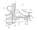
図4に、排ガスタービン過給機27のシールエア供給部79、軸受85等の概要を示す。コンプレッサケーシング93、軸受台95、およびタービンケーシング97内に、給気側コンプレッサ27aおよび排気タービン27bを備えた回転軸29が軸受85によって支持されて収納されている。シールエア供給路77は、給気側コンプレッサ27aの背面側の軸受台95に径方向に軸中心に向って伸びて給気側コンプレッサ27aの背面側の冷却を行い、その後軸中心部分で軸方向に伸び、排気タービン27bのタービンディスク99の背面側空間であるシールエア供給部79にシールエアを導くように形成されている。シールエア供給部79に導かれたシールエアによって、タービンディスク99のスラスト力をバランスさせ、さらに、軸受85を通って、軸受85の冷却や潤滑油のシールを行って、シールエア放出路89から放出されるようになっている。
In FIG. 4, the outline | summary of the seal
次に、排ガスタービン過給機27とは別に設けられたシールエア用圧縮機73について、このシールエア用圧縮機73が排ガスタービン過給機27と並列的に配置されて、ガスエンジン1の排ガスエネルギーによって駆動される場合に、エンジンの負荷変動があって、負荷に依らず所望とする給気およびエアシールが得られることを、図2を参照して説明する。
Next, for the
ガスエンジン1から排出される排ガスエネルギーは、排ガスの排気圧力(Pg)と排ガス流量(Q)との積によって求まり、このPg×Qはエンジンの負荷によって一意的に決まる。さらに、該エネルギーにより過給機が成し得る仕事量も、過給機出口側の排気圧力(Ps)と排ガス流量(Q')との積により、Ps×Q'も一意的に決まる。 The exhaust gas energy discharged from the gas engine 1 is determined by the product of the exhaust gas exhaust pressure (Pg) and the exhaust gas flow rate (Q), and this Pg × Q is uniquely determined by the engine load. Further, the amount of work that can be performed by the supercharger by the energy is also uniquely determined by the product of the exhaust pressure (Ps) on the supercharger outlet side and the exhaust gas flow rate (Q ′).
つまり、エンジン負荷に依らず、(Ps×Q')/(Pg×Q)=Const.となる。さらに、Pg×Qを分圧したそれぞれのエネルギーPg1×Q1およびPg2×Q2により成し得る仕事量Pg1'×Q1'およびPg2'×Q2'の各々の和も等しくなる。 That is, (Ps × Q ′) / (Pg × Q) = Const. It becomes. Furthermore, the sums of the work amounts Pg1 ′ × Q1 ′ and Pg2 ′ × Q2 ′ that can be achieved by the respective energy Pg1 × Q1 and Pg2 × Q2 obtained by dividing Pg × Q are also equal.
つまり、Pg×Q=(Pg1×Q1)+(Pg2×Q2)、Ps×Q'=(Ps1×Q1')+(Ps2×Q2')となり、エンジンン1の負荷変動に対して、各々の過給機の分担仕事の割合は常に一定であり、負荷に依らず所望の給気およびシールエアが得られる。 That is, Pg × Q = (Pg1 × Q1) + (Pg2 × Q2), Ps × Q ′ = (Ps1 × Q1 ′) + (Ps2 × Q2 ′). The ratio of the work shared by the supercharger is always constant, and desired air supply and seal air can be obtained regardless of the load.
従って、任意の負荷状態であってもシールエアが生成されるため、ガスエンジン1が運転されていれば、自動的に連動してシールエアが発生するので、シールエアが供給されずにガスエンジン1が運転し続けて排ガスタービン過給機27のシール不良やスラスト力バランス不良や、冷却不良を生じて過給機性能低下を引き起こし、エンジン性能低下を生じる恐れを回避でき、シールエアの供給装置の信頼性を向上できる。
Accordingly, since seal air is generated even in an arbitrary load state, if the gas engine 1 is in operation, the seal air is automatically generated and thus the gas engine 1 is operated without being supplied with the seal air. It is possible to avoid the possibility that the
以上のような第1実施形態によれば、メタンガスを燃料ガスとするガスエンジン1の排ガスタービン過給機27のシールエア用として設けたシールエア用圧縮機73からの加圧空気を、シールエア供給路77を介してシールエア供給部79に供給するので、メタンガスが予混合された給気混合ガスがシールエアとして用いられることがないため、給気混合ガスが排ガスタービン過給機27の高温部に直接接触する危険性を回避できる。
さらに、シールエア供給部79に供給されるのが空気であるため、シールエア供給部79に導かれたシールエアによって、タービンディスク99のスラスト力をバランスさせ、さらに、軸受85を通って、軸受85の冷却や潤滑油のシールを行って、シールエア放出路89から大気放出されても、メタンガスのように温室効果作用が大きくないため大気環境の悪化も防止される。
According to the first embodiment as described above, the pressurized air from the
Further, since air is supplied to the seal
また、シールエア用圧縮機73によって生成されたシールエアをシールエア供給部79に供給するシールエア供給路77から分岐して設けられシールエアの余剰空気を排ガスタービン過給機27の給気側コンプレッサ27aの出口側に導く余剰空気導入路81を備えたので、シールエアによる消費量を上回る余剰分が生じた場合には、排ガスタービン過給機27によって生成される加圧空気に、該余剰分を合流させることで、排ガスタービン過給機27の過給機効率を向上させることができる。
Further, the seal air generated by the
なお、制御装置61は、シールエア用圧縮機73によるシールエアの供給がシールエア用圧縮機73の故障等によりシールエアの供給が不可となった場合には、従来通り排ガスタービン過給機27が自給にてシールエアを供給し、前記ミキサ43へのガス供給量を制御するミキサガス調整弁51を閉じて、排ガスタービン過給機27の上流側におけるCMMガスの混合を停止して、各シリンダのガス供給枝管69から、各シリンダの給気枝管21への燃料ガスの供給だけによってガスエンジン1の運転継続が可能なように制御している。これによって、シールエアが供給されていない状態とならず、且つ排ガスタービン過給機27にメタンガスが混合した給気混合ガスを供給しないようにして、安全性を確保してシールエアの供給が不可時における一時的な運転の継続を可能とする。
When the supply of the seal air by the
(第2実施形態)
次に、第2実施形態のシールエア供給装置110について図3を参照して説明する。
第2実施形態は、第1実施形態のシールエア用圧縮機73に代えて、ガスエンジン1とは別に設けられた駆動モータ112によって駆動されるエアコンプレッサ114が設けられる。なお、駆動モータ112ではなくガスエンジン1とは別のエンジンによる駆動であってもよい。
(Second Embodiment)
Next, the seal air supply device 110 of the second embodiment will be described with reference to FIG.
In the second embodiment, an
図3のように、駆動モータ112で駆動されるエアコンプレッサ114からの加圧空気は、制御空気槽116に一時的に貯蔵される。その制御空気槽116では、調圧弁118によって一定の圧力(例えば、排ガスタービン過給機27のタービンディスク99のスラスト力をバランスさせるのに適した圧力等)に調圧され、その後、シールエア流量調整弁119によって流量調整されて、シールエア供給路77を通って排ガスタービン過給機27のシールエア供給部79へ供給される。
また、シールエア供給路77から分岐して余剰空気導入路81が形成され、余剰空気導入路81には余剰空気流量調整弁120(余剰空気流量調整手段)が設けられている。この余剰空気流量調整弁120を開くことで、シールエアの一部を排ガスタービン過給機27の給気側コンプレッサ27aの出口側へ排出できるようになっている。余剰空気流量調整弁120はシールエア圧が給気側コンプレッサ27aの出口側圧力よりも高い状態で、且つシールエアによる消費量を上回る余剰分が生じた場合に開作動して、シールエアの余剰分を排ガスタービン過給機27の給気側コンプレッサ27aの出口側の混合ガスへ導入可能としている。制御空気槽116の調圧弁118の制御や、シールエア流量調整弁119および余剰空気流量調整弁120のそれぞれの制御は、給気側コンプレッサ27aの出口側の圧力信号、制御空気槽116の圧力信号を基に制御装置122によって行われている。
As shown in FIG. 3, the pressurized air from the
Further, a surplus
このように、第2実施形態によると、ガスエンジン1とは別に設けられた駆動源によってエアコンプレッサ114を駆動し、その加圧空気を排ガスタービン過給機27にシールエアとして供給可能とするので、エンジン本体にエアシール用圧縮機の設置のための構造変更を行うことなく、既存の外部駆動源によって生成された加圧空気を利用することができるため、シールエアの供給装置を簡単に低コストで設置できる。その他の作用効果については、前記第1実施形態と同様の作用効果を有する。
Thus, according to the second embodiment, the
本発明によれば、ガスエンジンの排ガスタービン過給機のシールエアとして、排ガスタービン過給機とは別に設けたシールエア用圧縮機からの加圧空気を、シールエア供給路を介して排ガスタービン過給機のシールエア供給部に供給するので、メタンガス等の燃料ガスが予混合した給気混合ガスがシールエアとして用いられることがなく、該給気混合ガスが排ガスタービン過給機の高温部に直接接触する危険性が回避され、さらに、シールエア供給部に供給されるのが空気であるため、その供給後に大気に放出されても、メタンガスのように温室効果作用が大きくないため大気汚染も防止されるので、メタンガスを燃料とするガスエンジンにおける排ガスタービン過給機のシールエア供給装置に適している。 According to the present invention, as seal air for an exhaust gas turbine supercharger of a gas engine, compressed air from a seal air compressor provided separately from the exhaust gas turbine supercharger is used as an exhaust gas turbine supercharger via a seal air supply path. Therefore, there is no risk that the mixed gas premixed with methane or other fuel gas will be used as the sealed air, and that the mixed gas directly contacts the high temperature part of the exhaust gas turbocharger. In addition, since air is supplied to the seal air supply part, even if it is released to the atmosphere after its supply, since the greenhouse effect is not as great as methane gas, air pollution is also prevented. It is suitable for a seal air supply device of an exhaust gas turbocharger in a gas engine using methane gas as a fuel.
1 ガスエンジン
3 ガス供給管
5 大気導入管
25 給気冷却器
27 排ガスタービン過給機
27a 給気側コンプレッサ
73a コンプレッサ
27b、73b 排ガスタービ
29、75 回転軸
43 ミキサ
51 ミキサガス調整弁
55 シリンダガス調整弁
61、122 制御装置
63 シリンダ別ガス量調整弁
71、110 シールエア供給装置
73 シールエア用圧縮機
77 シールエア供給路
79 シールエア供給部
81 余剰空気導入路
83 逆止弁
85 軸受
89 シールエア放出路
99 タービンディスク
112 駆動モータ
114 エアコンプレッサ
DESCRIPTION OF SYMBOLS 1 Gas engine 3 Gas supply pipe 5
Claims (5)
Priority Applications (6)
| Application Number | Priority Date | Filing Date | Title |
|---|---|---|---|
| JP2010152374A JP5449062B2 (en) | 2010-07-02 | 2010-07-02 | Seal air supply device for exhaust gas turbocharger |
| EP11800627.9A EP2589770A4 (en) | 2010-07-02 | 2011-06-16 | Seal air supply apparatus and exhaust gas turbine supercharger using seal air supply apparatus |
| PCT/JP2011/063823 WO2012002161A1 (en) | 2010-07-02 | 2011-06-16 | Seal air supply apparatus and exhaust gas turbine supercharger using seal air supply apparatus |
| CN201180022001.0A CN102869867B (en) | 2010-07-02 | 2011-06-16 | Sealing air supplier and employ the exhaust-gas turbocharger of sealing air feeder |
| KR1020127028498A KR101399822B1 (en) | 2010-07-02 | 2011-06-16 | Seal air supply apparatus and exhaust gas turbine supercharger using seal air supply apparatus |
| US13/695,582 US8973361B2 (en) | 2010-07-02 | 2011-06-16 | Seal air supply system and exhaust gas turbine turbocharger using seal air supply system |
Applications Claiming Priority (1)
| Application Number | Priority Date | Filing Date | Title |
|---|---|---|---|
| JP2010152374A JP5449062B2 (en) | 2010-07-02 | 2010-07-02 | Seal air supply device for exhaust gas turbocharger |
Publications (2)
| Publication Number | Publication Date |
|---|---|
| JP2012013048A JP2012013048A (en) | 2012-01-19 |
| JP5449062B2 true JP5449062B2 (en) | 2014-03-19 |
Family
ID=45401886
Family Applications (1)
| Application Number | Title | Priority Date | Filing Date |
|---|---|---|---|
| JP2010152374A Expired - Fee Related JP5449062B2 (en) | 2010-07-02 | 2010-07-02 | Seal air supply device for exhaust gas turbocharger |
Country Status (6)
| Country | Link |
|---|---|
| US (1) | US8973361B2 (en) |
| EP (1) | EP2589770A4 (en) |
| JP (1) | JP5449062B2 (en) |
| KR (1) | KR101399822B1 (en) |
| CN (1) | CN102869867B (en) |
| WO (1) | WO2012002161A1 (en) |
Families Citing this family (18)
| Publication number | Priority date | Publication date | Assignee | Title |
|---|---|---|---|---|
| JP5314637B2 (en) * | 2010-05-31 | 2013-10-16 | 三菱重工業株式会社 | Gas engine |
| JP5308466B2 (en) * | 2011-01-31 | 2013-10-09 | 三菱重工業株式会社 | Fuel gas supply method and apparatus for gas engine |
| JP6030462B2 (en) * | 2013-01-30 | 2016-11-24 | 株式会社Ihi | Pressure incineration equipment and pressure incineration method |
| CH708276A1 (en) * | 2013-07-04 | 2015-01-15 | Liebherr Machines Bulle Sa | Gas engine. |
| US10054005B1 (en) * | 2013-09-24 | 2018-08-21 | Florida Turbine Technologies, Inc | Turbocharger with oil-free hydrostatic bearing |
| US9540952B2 (en) * | 2013-09-24 | 2017-01-10 | S & J Design, Llc | Turbocharger with oil-free hydrostatic bearing |
| WO2016078681A1 (en) * | 2014-11-20 | 2016-05-26 | Volvo Truck Corporation | A method and system for preventing oil escape |
| US10702786B2 (en) | 2015-03-18 | 2020-07-07 | B.L. Tech Limited | Noise generation device |
| US9746395B2 (en) * | 2015-05-21 | 2017-08-29 | Solar Turbines Incorporated | Exhaust fume isolator for a gas turbine engine |
| DE102015014550A1 (en) * | 2015-11-11 | 2017-05-11 | Man Diesel & Turbo Se | Intake system for an exhaust gas turbocharger and turbocharger |
| WO2017097733A1 (en) * | 2015-12-07 | 2017-06-15 | Dürr Systems Ag | A mixing and processing system of ventilation air methane and coal mine methane |
| DE102017200363B4 (en) | 2016-02-04 | 2022-07-07 | Ford Global Technologies, Llc | Method for operating a parallel-charged internal combustion engine with switchable turbine and internal combustion engine for carrying out such a method |
| US9995206B2 (en) * | 2016-04-08 | 2018-06-12 | Southwest Research Institute | Intake air boost system for two-cycle engine having turbo-supercharger |
| US10563915B2 (en) | 2017-04-03 | 2020-02-18 | John Paul Mackillop | Instrument air system and method |
| CN107885183B (en) * | 2017-09-21 | 2020-03-24 | 北汽福田汽车股份有限公司 | Supercharging pre-control calibration method and system for engine turbocharging and vehicle |
| CN109964013B (en) * | 2017-10-26 | 2021-10-22 | 三菱重工发动机和增压器株式会社 | Turbocharger |
| US10920682B2 (en) * | 2018-11-02 | 2021-02-16 | Rem Technology Inc. | Intake air assessment for industrial engines |
| CN109989830A (en) * | 2019-05-23 | 2019-07-09 | 中国船舶重工集团公司第七0三研究所 | Reduce the supercharging air system of turbine oil leakage |
Family Cites Families (24)
| Publication number | Priority date | Publication date | Assignee | Title |
|---|---|---|---|---|
| US4207035A (en) * | 1977-12-27 | 1980-06-10 | Cummins Engine Company, Inc. | Turbocharger assembly |
| US4472107A (en) * | 1982-08-03 | 1984-09-18 | Union Carbide Corporation | Rotary fluid handling machine having reduced fluid leakage |
| US4599862A (en) * | 1985-02-05 | 1986-07-15 | Bergeron Robert M | Turbocharger for two-cycle engines and method of operation thereof |
| DE3704967C1 (en) * | 1987-02-17 | 1988-05-11 | Mtu Friedrichshafen Gmbh | Supercharged multi-cylinder reciprocating internal combustion engine with several exhaust gas turbochargers working in parallel |
| US5076765A (en) * | 1988-08-03 | 1991-12-31 | Nissan Motor Company, Altd. | Shaft seal arrangement of turbocharger |
| JP2552282Y2 (en) * | 1990-10-22 | 1997-10-29 | 三菱重工業株式会社 | Exhaust gas turbocharger |
| JPH06346749A (en) | 1993-06-04 | 1994-12-20 | Mitsubishi Heavy Ind Ltd | Exhaust turbo-supercharger |
| US6062026A (en) * | 1997-05-30 | 2000-05-16 | Turbodyne Systems, Inc. | Turbocharging systems for internal combustion engines |
| JPH11117753A (en) | 1997-10-20 | 1999-04-27 | Mitsubishi Heavy Ind Ltd | Seal air supplying device for exhaust gas turbine supercharger |
| DE19928925A1 (en) * | 1999-06-24 | 2000-12-28 | Asea Brown Boveri | turbocharger |
| DE60128967T2 (en) * | 2001-06-26 | 2008-02-28 | Volvo Lastvagnar Ab | GAS TURBINE DEVICE |
| JP4108061B2 (en) * | 2004-04-16 | 2008-06-25 | 三菱重工業株式会社 | EGR system for turbocharged engine |
| EP1766195B1 (en) * | 2004-07-09 | 2010-08-25 | Honeywell International Inc. | Turbocharger housing, turbocharger and a multiturbocharger system |
| CN100575679C (en) * | 2005-02-24 | 2009-12-30 | 克诺尔商用车制动系统有限公司 | Internal-combustion engine dilution air plant and the method for improving the internal-combustion engine acceleration and discharging |
| US7836694B2 (en) * | 2005-05-06 | 2010-11-23 | Honeywell International Inc. | Air bearing turbo cooling air flow regulating device |
| GB0512543D0 (en) * | 2005-06-20 | 2005-07-27 | Ricardo Uk Ltd | Supercharged diesel engines |
| DE102006037821A1 (en) * | 2006-08-12 | 2008-02-14 | Atlas Copco Energas Gmbh | turbomachinery |
| DE102007019060A1 (en) * | 2007-04-23 | 2008-11-20 | Audi Ag | Internal-combustion engine for motor vehicle, has mechanical loader arranged in intake system in parallel connection to compressor of turbocharger, and switched into upper speed range of engine to adjust power loss of turbocharger |
| CN101451481A (en) * | 2007-11-30 | 2009-06-10 | 卡特彼勒科技新加坡有限公司 | Compression-ignition engine with combined features for reducing emission |
| JP4563443B2 (en) | 2007-12-14 | 2010-10-13 | 三菱重工業株式会社 | Gas engine system control method and system |
| US8100636B2 (en) * | 2008-03-26 | 2012-01-24 | Air Liquide Process & Construction, Inc. | Recovery of expander-booster leak gas |
| GB0814764D0 (en) * | 2008-08-13 | 2008-09-17 | Cummins Turbo Tech Ltd | Engine braking method and system |
| EP2336571A1 (en) * | 2009-12-15 | 2011-06-22 | Perkins Engines Company Limited | System for reducing compressor oil consumption |
| US8915708B2 (en) * | 2011-06-24 | 2014-12-23 | Caterpillar Inc. | Turbocharger with air buffer seal |
-
2010
- 2010-07-02 JP JP2010152374A patent/JP5449062B2/en not_active Expired - Fee Related
-
2011
- 2011-06-16 US US13/695,582 patent/US8973361B2/en not_active Expired - Fee Related
- 2011-06-16 WO PCT/JP2011/063823 patent/WO2012002161A1/en active Application Filing
- 2011-06-16 EP EP11800627.9A patent/EP2589770A4/en not_active Withdrawn
- 2011-06-16 CN CN201180022001.0A patent/CN102869867B/en not_active Expired - Fee Related
- 2011-06-16 KR KR1020127028498A patent/KR101399822B1/en not_active IP Right Cessation
Also Published As
| Publication number | Publication date |
|---|---|
| WO2012002161A1 (en) | 2012-01-05 |
| KR101399822B1 (en) | 2014-05-27 |
| KR20130018826A (en) | 2013-02-25 |
| US8973361B2 (en) | 2015-03-10 |
| CN102869867B (en) | 2015-11-25 |
| US20130101401A1 (en) | 2013-04-25 |
| EP2589770A4 (en) | 2017-12-27 |
| CN102869867A (en) | 2013-01-09 |
| EP2589770A1 (en) | 2013-05-08 |
| JP2012013048A (en) | 2012-01-19 |
Similar Documents
| Publication | Publication Date | Title |
|---|---|---|
| JP5449062B2 (en) | Seal air supply device for exhaust gas turbocharger | |
| US20180283273A1 (en) | Method and system for controlling secondary flow system | |
| JP4563443B2 (en) | Gas engine system control method and system | |
| JP5314719B2 (en) | Gas engine air supply device | |
| JP5308466B2 (en) | Fuel gas supply method and apparatus for gas engine | |
| KR101599681B1 (en) | Hull resistance reduction system and hull resistance reduction method | |
| JP4247191B2 (en) | Gas supply device and operation method for gas engine | |
| EP2247838A2 (en) | Supercharger arrangement for a piston engine | |
| RU2628166C2 (en) | Method for operation of gas-turbine power plant with spent gas recycling and corresponding gas-turbine power plant | |
| CA2576683A1 (en) | Aircraft auxiliary gas turbine engine and method for operating | |
| CN103608567A (en) | Gas turbine arrangement for a locomotive | |
| US8109093B2 (en) | Method and an arrangement in connection with a turbocharged piston engine | |
| US20230134352A1 (en) | Emissions management modules and associated systems and methods | |
| JP5918722B2 (en) | Diesel engine and method for improving output of the diesel engine | |
| JP4865241B2 (en) | Gas supply device for gas engine and gas engine provided with the gas supply device | |
| JP5073039B2 (en) | Gas supply device for gas engine and gas engine provided with the gas supply device | |
| JP2013148082A (en) | Gas turbine device | |
| JP5804756B2 (en) | Supercharger system, internal combustion engine, and supercharger system control method | |
| JP5461226B2 (en) | Two-stage turbocharging system | |
| CN110832179B (en) | Supercharger residual power recovery device for internal combustion engine, and ship | |
| GB2539903A (en) | Mounting assembly for turbo aftercooler modules | |
| US20200340713A1 (en) | Gas heat pump system | |
| JP2010077930A (en) | Bleed type gas turbine engine | |
| KR20120097096A (en) | Turbo charger for engine |
Legal Events
| Date | Code | Title | Description |
|---|---|---|---|
| A621 | Written request for application examination |
Free format text: JAPANESE INTERMEDIATE CODE: A621 Effective date: 20120220 |
|
| A131 | Notification of reasons for refusal |
Free format text: JAPANESE INTERMEDIATE CODE: A131 Effective date: 20130402 |
|
| A521 | Written amendment |
Free format text: JAPANESE INTERMEDIATE CODE: A523 Effective date: 20130527 |
|
| TRDD | Decision of grant or rejection written | ||
| A01 | Written decision to grant a patent or to grant a registration (utility model) |
Free format text: JAPANESE INTERMEDIATE CODE: A01 Effective date: 20131203 |
|
| A61 | First payment of annual fees (during grant procedure) |
Free format text: JAPANESE INTERMEDIATE CODE: A61 Effective date: 20131224 |
|
| R151 | Written notification of patent or utility model registration |
Ref document number: 5449062 Country of ref document: JP Free format text: JAPANESE INTERMEDIATE CODE: R151 |
|
| LAPS | Cancellation because of no payment of annual fees |