WO2012002161A1 - Seal air supply apparatus and exhaust gas turbine supercharger using seal air supply apparatus - Google Patents
Seal air supply apparatus and exhaust gas turbine supercharger using seal air supply apparatus Download PDFInfo
- Publication number
- WO2012002161A1 WO2012002161A1 PCT/JP2011/063823 JP2011063823W WO2012002161A1 WO 2012002161 A1 WO2012002161 A1 WO 2012002161A1 JP 2011063823 W JP2011063823 W JP 2011063823W WO 2012002161 A1 WO2012002161 A1 WO 2012002161A1
- Authority
- WO
- WIPO (PCT)
- Prior art keywords
- seal air
- air
- exhaust gas
- seal
- gas
- Prior art date
Links
Images


Classifications
-
- F—MECHANICAL ENGINEERING; LIGHTING; HEATING; WEAPONS; BLASTING
- F04—POSITIVE - DISPLACEMENT MACHINES FOR LIQUIDS; PUMPS FOR LIQUIDS OR ELASTIC FLUIDS
- F04D—NON-POSITIVE-DISPLACEMENT PUMPS
- F04D29/00—Details, component parts, or accessories
-
- F—MECHANICAL ENGINEERING; LIGHTING; HEATING; WEAPONS; BLASTING
- F02—COMBUSTION ENGINES; HOT-GAS OR COMBUSTION-PRODUCT ENGINE PLANTS
- F02M—SUPPLYING COMBUSTION ENGINES IN GENERAL WITH COMBUSTIBLE MIXTURES OR CONSTITUENTS THEREOF
- F02M21/00—Apparatus for supplying engines with non-liquid fuels, e.g. gaseous fuels stored in liquid form
- F02M21/02—Apparatus for supplying engines with non-liquid fuels, e.g. gaseous fuels stored in liquid form for gaseous fuels
-
- F—MECHANICAL ENGINEERING; LIGHTING; HEATING; WEAPONS; BLASTING
- F01—MACHINES OR ENGINES IN GENERAL; ENGINE PLANTS IN GENERAL; STEAM ENGINES
- F01D—NON-POSITIVE DISPLACEMENT MACHINES OR ENGINES, e.g. STEAM TURBINES
- F01D11/00—Preventing or minimising internal leakage of working-fluid, e.g. between stages
- F01D11/02—Preventing or minimising internal leakage of working-fluid, e.g. between stages by non-contact sealings, e.g. of labyrinth type
- F01D11/04—Preventing or minimising internal leakage of working-fluid, e.g. between stages by non-contact sealings, e.g. of labyrinth type using sealing fluid, e.g. steam
-
- F—MECHANICAL ENGINEERING; LIGHTING; HEATING; WEAPONS; BLASTING
- F02—COMBUSTION ENGINES; HOT-GAS OR COMBUSTION-PRODUCT ENGINE PLANTS
- F02B—INTERNAL-COMBUSTION PISTON ENGINES; COMBUSTION ENGINES IN GENERAL
- F02B37/00—Engines characterised by provision of pumps driven at least for part of the time by exhaust
- F02B37/001—Engines characterised by provision of pumps driven at least for part of the time by exhaust using exhaust drives arranged in parallel
-
- F—MECHANICAL ENGINEERING; LIGHTING; HEATING; WEAPONS; BLASTING
- F02—COMBUSTION ENGINES; HOT-GAS OR COMBUSTION-PRODUCT ENGINE PLANTS
- F02B—INTERNAL-COMBUSTION PISTON ENGINES; COMBUSTION ENGINES IN GENERAL
- F02B37/00—Engines characterised by provision of pumps driven at least for part of the time by exhaust
- F02B37/007—Engines characterised by provision of pumps driven at least for part of the time by exhaust with exhaust-driven pumps arranged in parallel, e.g. at least one pump supplying alternatively
-
- F—MECHANICAL ENGINEERING; LIGHTING; HEATING; WEAPONS; BLASTING
- F02—COMBUSTION ENGINES; HOT-GAS OR COMBUSTION-PRODUCT ENGINE PLANTS
- F02B—INTERNAL-COMBUSTION PISTON ENGINES; COMBUSTION ENGINES IN GENERAL
- F02B37/00—Engines characterised by provision of pumps driven at least for part of the time by exhaust
- F02B37/12—Control of the pumps
- F02B37/16—Control of the pumps by bypassing charging air
-
- F—MECHANICAL ENGINEERING; LIGHTING; HEATING; WEAPONS; BLASTING
- F02—COMBUSTION ENGINES; HOT-GAS OR COMBUSTION-PRODUCT ENGINE PLANTS
- F02B—INTERNAL-COMBUSTION PISTON ENGINES; COMBUSTION ENGINES IN GENERAL
- F02B39/00—Component parts, details, or accessories relating to, driven charging or scavenging pumps, not provided for in groups F02B33/00 - F02B37/00
- F02B39/16—Other safety measures for, or other control of, pumps
-
- F—MECHANICAL ENGINEERING; LIGHTING; HEATING; WEAPONS; BLASTING
- F02—COMBUSTION ENGINES; HOT-GAS OR COMBUSTION-PRODUCT ENGINE PLANTS
- F02C—GAS-TURBINE PLANTS; AIR INTAKES FOR JET-PROPULSION PLANTS; CONTROLLING FUEL SUPPLY IN AIR-BREATHING JET-PROPULSION PLANTS
- F02C6/00—Plural gas-turbine plants; Combinations of gas-turbine plants with other apparatus; Adaptations of gas- turbine plants for special use
- F02C6/04—Gas-turbine plants providing heated or pressurised working fluid for other apparatus, e.g. without mechanical power output
- F02C6/10—Gas-turbine plants providing heated or pressurised working fluid for other apparatus, e.g. without mechanical power output supplying working fluid to a user, e.g. a chemical process, which returns working fluid to a turbine of the plant
- F02C6/12—Turbochargers, i.e. plants for augmenting mechanical power output of internal-combustion piston engines by increase of charge pressure
-
- F—MECHANICAL ENGINEERING; LIGHTING; HEATING; WEAPONS; BLASTING
- F02—COMBUSTION ENGINES; HOT-GAS OR COMBUSTION-PRODUCT ENGINE PLANTS
- F02C—GAS-TURBINE PLANTS; AIR INTAKES FOR JET-PROPULSION PLANTS; CONTROLLING FUEL SUPPLY IN AIR-BREATHING JET-PROPULSION PLANTS
- F02C7/00—Features, components parts, details or accessories, not provided for in, or of interest apart form groups F02C1/00 - F02C6/00; Air intakes for jet-propulsion plants
- F02C7/28—Arrangement of seals
-
- F—MECHANICAL ENGINEERING; LIGHTING; HEATING; WEAPONS; BLASTING
- F05—INDEXING SCHEMES RELATING TO ENGINES OR PUMPS IN VARIOUS SUBCLASSES OF CLASSES F01-F04
- F05D—INDEXING SCHEME FOR ASPECTS RELATING TO NON-POSITIVE-DISPLACEMENT MACHINES OR ENGINES, GAS-TURBINES OR JET-PROPULSION PLANTS
- F05D2220/00—Application
- F05D2220/40—Application in turbochargers
-
- Y—GENERAL TAGGING OF NEW TECHNOLOGICAL DEVELOPMENTS; GENERAL TAGGING OF CROSS-SECTIONAL TECHNOLOGIES SPANNING OVER SEVERAL SECTIONS OF THE IPC; TECHNICAL SUBJECTS COVERED BY FORMER USPC CROSS-REFERENCE ART COLLECTIONS [XRACs] AND DIGESTS
- Y02—TECHNOLOGIES OR APPLICATIONS FOR MITIGATION OR ADAPTATION AGAINST CLIMATE CHANGE
- Y02T—CLIMATE CHANGE MITIGATION TECHNOLOGIES RELATED TO TRANSPORTATION
- Y02T10/00—Road transport of goods or passengers
- Y02T10/10—Internal combustion engine [ICE] based vehicles
- Y02T10/12—Improving ICE efficiencies
Definitions
- the present invention relates to a seal air supply device and an exhaust gas turbine supercharger using the seal air supply device, and more particularly, to a mixed gas obtained by premixing air and a part or all of a fuel gas via an exhaust gas turbine supercharger.
- the present invention relates to a seal air supply device for an exhaust gas turbine supercharger in a gas engine supplied to a cylinder.
- an exhaust gas turbocharger provided in an engine, in order to prevent the exhaust from the engine from entering the supply side of the exhaust gas turbine supercharger, and the thrust force of the exhaust turbine of the exhaust gas turbine supercharger
- a part of the supply air supplied to the supply side compressor of the exhaust gas turbine supercharger, or the supply side compressor A part of the pressurized air supply is extracted and supplied to the exhaust turbine rear space, bearings, and the like (hereinafter referred to as seal air). After the supply, the seal air is released into the atmosphere.
- Patent Document 1 Japanese Patent Application Laid-Open No. 6-346749
- the low temperature of the main engine scavenging chamber secondary side 03 pressurized by the supercharger 01 and then cooled by the cooler 02 is disclosed.
- Air is supplied as seal air to the side surface of the turbine disk provided on the turbine 04 side of the turbocharger 01 so as to cool the turbine blade and turbine disk section in addition to the original functions (thrust balance, oil seal and gas seal). What has been disclosed is disclosed.
- Patent Document 2 Japanese Patent Application Laid-Open No. 11-117753
- compressed air from the compressor of the supercharger is guided to the back of the turbine through the seal air passage, and the rotor shaft balance action, exhaust gas intrusion, and lubricating oil
- an automatic valve that opens the air passage when the air pressure on the outlet side of the compressor is higher than the pressure on the turbine back space side is disclosed in the middle of the sealing air passage.
- Patent Document 3 Japanese Unexamined Patent Application Publication No. 2009-144626
- a part or all of the fuel gas is used.
- a pre-supercharger premixing air supply system in which the mixed gas is preliminarily mixed with the supply air and then the mixed gas is pressurized by a supercharger and supplied into a cylinder.
- an exhaust gas turbocharger is provided with an air-fuel mixture gas obtained by premixing air and a part or all of the fuel gas upstream of the exhaust gas turbine supercharger.
- the objective is to reduce air emissions and prevent air pollution.
- a supply air mixed gas in which air and a part or all of the fuel gas are premixed on the upstream side of the exhaust gas turbine supercharger is supplied to the combustion chamber via the exhaust gas turbine supercharger.
- a seal air compressor is provided separately from the exhaust gas turbine supercharger, and the compressed air generated by the seal air compressor is supplied to the exhaust gas turbine supercharger.
- the pressurized air from the seal air compressor provided separately from the exhaust gas turbine supercharger is passed through the seal air supply path. Therefore, the air-fuel mixture gas in which fuel gas such as methane gas is premixed is not used as the seal air, and the air-fuel mixture gas directly contacts the high temperature portion of the exhaust gas turbine supercharger. The possibility is avoided. Furthermore, since air is supplied to the seal air supply unit, even if the air supplied to the seal air supply unit is released to the atmosphere, the greenhouse effect is not as great as that of methane gas, so air pollution is also suppressed.
- a seal air discharge path for returning the seal air that has passed through the seal air supply unit to the compressor inlet side of the exhaust gas turbine is provided.
- the seal air supplied to the seal air supply unit prevents the exhaust of the engine from entering the supply side of the exhaust gas turbine supercharger, balances the thrust force of the exhaust turbine, and further provides the supply side compressor.
- the back side cooling of the exhaust side turbine is performed and the exhaust gas turbine is joined to the compressor inlet side of the exhaust gas turbine through the seal air discharge path, so that the supercharger efficiency of the exhaust gas turbine supercharger can be improved.
- the deterioration of the atmospheric environment due to the greenhouse effect is also suppressed.
- the seal air compressor is an exhaust gas turbine compressor that is provided in parallel to the exhaust gas turbine supercharger and driven by the exhaust gas with respect to the exhaust gas flow of the gas engine.
- the seal air compressor is mainly used as a seal air exhaust gas turbine compressor because it is installed in parallel with the exhaust gas turbine compressor with respect to the exhaust gas flow of the gas engine and is provided only to generate seal air.
- a compressor having a smaller capacity than the exhaust gas turbocharger may be used. Then, both the exhaust gas turbine supercharger and the seal air exhaust gas turbine compressor are driven by the exhaust gas of the gas engine.
- the generation of seal air is linked to the operating state of the gas engine, so that the seal engine is not supplied to the exhaust gas turbocharger and the gas engine continues to operate, resulting in poor seals and thrust force It is possible to avoid the possibility that the engine performance will be reduced due to the poor balance or the poor cooling caused by the supercharger performance. As a result, the reliability of the sealing air supply device can be improved.
- the seal air compressor is driven by a driving means provided separately from the gas engine, for example, by a drive source such as an electric motor or another engine.
- a drive source such as an electric motor or another engine.
- the compressor for sealing air is driven by driving means different from the gas engine, and the pressurized air can be supplied to the exhaust gas turbine supercharger as sealing air.
- a seal air supply device can be obtained easily and at low cost without any structural change.
- a check valve that allows only the flow of seal air to the compressor outlet side of the exhaust gas turbine supercharger is provided in the surplus air introduction path. Since the high-pressure air-fuel mixture gas at the compressor outlet side of the exhaust gas turbine supercharger does not flow back into the surplus air introduction path, surplus exceeding the consumption by the seal air is added to the pressurized air generated by the seal air compressor Only when the pressure is higher than the outlet side of the exhaust gas turbine supercharger, the surplus can be merged with the outlet side of the exhaust gas turbine supercharger. The surplus air can be reliably introduced into the air-fuel mixture gas on the outlet side of the compressor of the machine.
- a compressor for seal air is provided separately from the exhaust gas turbine supercharger, and pressurized air generated by the compressor for seal air is used as seal air for the exhaust gas turbine supercharger.
- the gas engine 1 is a power generation gas engine with a supercharger, and will be described in the form in which a methane-containing gas that is disposed in the vicinity of a coal mine and is discharged from a coal mine as fuel gas and intake gas is used.
- Recovered methane-containing gas CMM (Coal Mine Methane, methane concentration 30-50% by weight, which is mixed in the coal bed and recovered by a vacuum pump from the vent hole for the sake of safety. ) And ventilated methane-containing gas VAM (Ventilation Air Methane, methane concentration: 0.3 to 0.7% by weight) discharged from the tunnel and face for ventilation.
- CMM Coal Mine Methane, methane concentration 30-50% by weight, which is mixed in the coal bed and recovered by a vacuum pump from the vent hole for the sake of safety.
- VAM Vententilation Air Methane, methane concentration: 0.3 to 0.7% by weight
- the recovered methane-containing gas CMM is used as a fuel gas to be supplied to the gas supply pipe 3, and the ventilation methane-containing gas VAM is mixed with the atmosphere (air) or VAM is not mixed. Then, only the atmosphere is supplied to the atmosphere introduction pipe 5.
- the gas engine 1 disposed in the vicinity of the coal mine is described.
- the present invention is not limited to this.
- biomass gas or the like is used as the fuel gas, and the garbage disposal site is used as the premixed fuel gas with the atmosphere.
- a gas having a methane concentration lower than the flammable limit, such as landfill gas generated in, may be used.
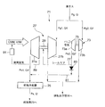
- a power generation gas engine 1 includes an engine body 7 having a plurality of (three in FIG. 1) combustion cylinders in which a combustion chamber is formed, and a generator 9 is an output shaft of the engine body 7. 11.
- a flywheel 13 is attached to the output shaft 11, an engine rotation sensor 15 is provided outside the flywheel 13, and the load of the generator 9 is detected by a load sensor 17 to detect the engine load. .
- An air supply branch pipe 21 is connected to each cylinder head 19 in the cylinder head 19 of the gas engine 1. These air supply branch pipes 21 are connected to an air supply pipe 23, and the air supply pipe 23 is an air supply for cooling the air supply. It is connected to the cooler 25 and further connected to the supply air outlet of the supply side compressor 27a of the exhaust gas turbine supercharger 27 (exhaust gas turbine supercharger). In this exhaust gas turbine supercharger 27, an intake side compressor 27a and an exhaust turbine 27b are connected by a rotary shaft 29, and the exhaust turbine 27b is driven by the exhaust gas flow to pressurize the mixed gas by the supply side compressor 27a. Supply to the combustion cylinder of the main body 7.
- each cylinder head 19 is connected to an exhaust pipe 31, each exhaust pipe 31 is connected to an exhaust collecting pipe 33, and exhaust gas from the exhaust collecting pipe 33 is introduced into an exhaust turbine 27 b of the exhaust gas turbine supercharger 27. And is discharged through the exhaust outlet pipe 35.
- an exhaust bypass pipe 37 is provided which branches from the inlet side of the exhaust turbine 27b and bypasses the exhaust turbine 27b and is connected to the outlet side of the exhaust turbine 27b.
- the exhaust bypass pipe 37 is provided with an exhaust bypass valve 39 that changes the passage area of the exhaust bypass pipe 37.
- a mixer 43 is installed between the supercharger inlet pipe 41 and the air introduction pipe 5 for supplying the air-fuel mixture gas to the exhaust gas turbine supercharger 27.
- the mixer 43 a part of the CMM gas of the fuel gas supplied from the gas supply pipe 3 is mixed with the air from the atmosphere introduction pipe 5 or the mixed atmosphere of air and VAM gas.
- the supply air mixed gas is pressurized by an air supply side compressor 27 a of the exhaust gas turbine supercharger 27.
- the gas supply pipe 3 branches in the middle, and is branched from the gas supply pipe 3 into a supercharger side gas supply pipe 45 and a cylinder side gas supply pipe 47.
- the supercharger side gas supply pipe 45 is connected to the mixer 43, and the supercharger side gas supply pipe 45 is provided with a gas flow meter 49 and a mixer gas adjustment valve 51 for controlling the gas supply amount to the mixer 43.
- the cylinder-by-cylinder gas gas regulating valve 63 provided in the gas supply branch pipe 69 described later can be downsized.
- the cylinder side gas supply pipe 47 is connected to the supply branch pipe 21 of each cylinder, and is added by an exhaust gas turbine supercharger 27 that flows in the supply branch pipe 21 before being supplied to the combustion chamber in the cylinder. Further mixed with the pressurized mixed gas and flows into the combustion chamber.
- the cylinder side gas supply pipe 47 is provided with a gas flow meter 53 and a cylinder gas adjustment valve 55 for controlling the gas supply amount to the cylinder.
- the gas supply pipe 3 is provided with a strainer 57 and a fuel demister 59.
- a control device 61 is provided, and the opening degree of the gas regulating valve 63 for each cylinder provided in each gas supply branch pipe 69 so as to achieve the target rotational speed based on the engine rotational speed signal from the rotational speed sensor 15, and the supercharger
- the opening degree of the mixer gas adjustment valve 51 provided in the side gas supply pipe 45 is controlled. Further, in the control device 61, the engine speed signal from the speed sensor 15, the engine load signal from the load sensor 17, the supply pressure signal from the supply pressure sensor 65, and the supply air temperature from the supply temperature sensor 67. Based on the signal, the opening degree of the exhaust bypass valve 39 is controlled to a predetermined air-fuel ratio.
- the fuel gas from the gas supply pipe 3 passes through a strainer 57 and a fuel demister 59 provided in the gas supply pipe 3, and a lot of dust contained when discharged from the coal mine. Impurities such as water vapor are removed. Then, the fuel gas that has passed through the fuel demister 59 is branched in the middle, and one of the branched fuel gases is introduced into the mixer 43 through the supercharger side gas supply pipe 45, and the mixer 43 passes through the atmosphere introduction pipe 5. Then, the mixed gas is introduced into the air supply side compressor 27a of the exhaust gas turbine supercharger 27 as an air supply mixed gas.
- the air-fuel mixture gas pressurized to a high temperature and high pressure by the air-supply side compressor 27a is cooled by the air-supply cooler 25 and cooled down, and flows into the air supply branch pipe 21 of each cylinder through the air supply pipe 23.
- the other of the branched fuel gas enters the cylinder side gas supply pipe 47, enters the supply branch pipe 21 of each cylinder from the gas supply branch pipe 69 of each cylinder, and mixes the supply air in the supply branch pipe 21. It is mixed with gas and sent into each cylinder.
- the exhaust gas from each cylinder of the gas engine 1 is merged in the exhaust collecting pipe 33 through the exhaust pipe 31, and is supplied to the exhaust turbine 27b of the exhaust gas turbine supercharger 27 to drive the exhaust turbine 27b. It is discharged to the outside through the outlet pipe 35.
- the exhaust gas is discharged by controlling the exhaust bypass valve 39 by a control operation signal from the control device 61, and a part of the exhaust gas in the exhaust collecting pipe 33 is discharged to the exhaust outlet pipe 35 by bypassing the exhaust turbine 27b.
- the pressurized flow rate by the exhaust gas turbine supercharger 27 is controlled.
- FIG. 2 is a configuration diagram of the seal air supply device 71, and is a detailed explanatory view of a portion A in FIG.
- a seal air compressor 73 Separately from the exhaust gas turbine supercharger 27, which is the main supercharger, a seal air compressor 73 as a sub-supercharger is provided in the vicinity of the exhaust gas turbine supercharger 27 in the flow of exhaust gas from the exhaust gas turbine supercharger 27 and the gas engine. On the other hand, they are installed in parallel.
- the seal air compressor 73 is an exhaust gas composed of an exhaust turbine 73 b driven by a part of the exhaust gas discharged from the exhaust collecting pipe 33, and a compressor 73 a coupled to the exhaust turbine 73 b and the rotary shaft 75. Turbine compressor. And air (air) is made to flow into compressor 73a. Further, the exhaust gas that has passed through the exhaust turbine 73 b of the seal air compressor 73 joins the exhaust gas that has passed through the exhaust turbine 27 b of the exhaust gas turbine supercharger 27 and is discharged.
- the pressurized air pressurized by the compressor 73a of the compressor 73 for the seal air is used as the seal air for the exhaust gas turbine supercharger 27 via the seal air supply passage 77, and the seal air supply unit 79 (turbine of the exhaust gas turbine supercharger 27). It is supplied to the back side space of the disk 99 (see FIG. 4).
- the seal air supply path 77 is branched in the middle to form an excess air introduction path 81 that guides the surplus air of the seal air to the seal air supply unit 79 to the outlet side of the supply side compressor 27a of the exhaust gas turbine supercharger 27.
- the surplus air introduction path 81 is provided with a check valve 83 that allows only the flow to the outlet side of the supply side compressor 27a, thereby preventing backflow from the outlet side of the supply side compressor 27a.
- the high-pressure air-fuel mixture gas on the outlet side of the air-supply side compressor 27 a of the exhaust gas turbine supercharger 27 is prevented from flowing back into the surplus air introduction path 81, so that it is generated by the seal air compressor 73. Only when surplus exceeding the amount consumed by the seal air occurs in the pressurized air and when the pressure becomes higher than the outlet side of the exhaust gas turbine supercharger 27, the surplus is removed from the air supply side compressor 27a. It is possible to join the outlet side, and it is possible to reliably introduce surplus air into the supply air mixed gas on the outlet side of the supply side compressor 27a.
- the seal air supplied to the seal air supply unit 79 is then discharged from the seal air discharge port 89 (see FIG. 4) by cooling and sealing the portion of the bearing 85 (see FIG. 4), and then released.
- the air is supplied to the inlet side of the supply side compressor 27 a of the exhaust gas turbine supercharger 27 through the seal air discharge path 89.
- An oil mist filter 91 is provided in the seal air discharge path 89. Since the seal air passes through the seal air supply unit 79, the bearing 85, and the like, the intrusion of exhaust gas, the thrust balance of the exhaust turbine 27b, and the leakage of lubricating oil are prevented. As clean air from which the air has been removed, it flows into the upstream side of the supply side compressor 27a of the exhaust gas turbine supercharger 27.
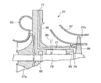
- FIG. 4 shows an outline of the seal air supply unit 79, the bearing 85, and the like of the exhaust gas turbine supercharger 27.
- the rotary shaft 29 including the supply side compressor 27 a and the exhaust turbine 27 b is supported and accommodated by a bearing 85.
- the seal air supply passage 77 extends radially toward the shaft support 95 on the back side of the air supply side compressor 27a to cool the back side of the air supply side compressor 27a, and then axially at the shaft center portion.
- the seal air is formed to extend to the seal air supply part 79 which is a space on the back side of the turbine disk 99 of the exhaust turbine 27b.
- the thrust force of the turbine disk 99 is balanced by the seal air guided to the seal air supply unit 79, and further, the bearing 85 is cooled and the lubricating oil is sealed through the bearing 85, and is discharged from the seal air discharge passage 89. It is like that.
- the seal air compressor 73 provided separately from the exhaust gas turbine supercharger 27, the seal air compressor 73 is arranged in parallel with the exhaust gas turbine supercharger 27, and the exhaust gas energy of the gas engine 1 With reference to FIG. 2, it will be described that, when driven, there is a fluctuation in the engine load, and a desired air supply and air seal can be obtained regardless of the load.
- the exhaust gas energy discharged from the gas engine 1 is determined by the product of the exhaust gas exhaust pressure (Pg) and the exhaust gas flow rate (Q), and this Pg ⁇ Q is uniquely determined by the engine load. Further, the amount of work that can be performed by the supercharger by the energy is also uniquely determined by the product of the exhaust pressure (Ps) on the supercharger outlet side and the exhaust gas flow rate (Q ′).
- seal air is generated even in an arbitrary load state, if the gas engine 1 is in operation, the seal air is automatically generated and thus the gas engine 1 is operated without being supplied with the seal air. It is possible to avoid the possibility that the exhaust gas turbocharger 27 will have a poor seal, a poor thrust balance, or a poor cooling, leading to a decrease in the performance of the turbocharger and a decrease in the engine performance. It can be improved.
- the pressurized air from the seal air compressor 73 provided for the seal air of the exhaust gas turbocharger 27 of the gas engine 1 using methane gas as the fuel gas is used as the seal air supply path 77. Since the supply air mixed gas in which methane gas is premixed is not used as the seal air, the supply air mixed gas directly contacts the high temperature portion of the exhaust gas turbine supercharger 27. Risk can be avoided. Further, since air is supplied to the seal air supply unit 79, the thrust force of the turbine disk 99 is balanced by the seal air guided to the seal air supply unit 79, and further, the cooling of the bearing 85 is performed through the bearing 85. Even if sealing is performed with lubricating oil and the air is released from the sealing air discharge passage 89, the greenhouse effect is not as great as that of methane gas, so that the deterioration of the air environment is also prevented.
- the seal air generated by the seal air compressor 73 is branched from a seal air supply passage 77 that supplies the seal air to the seal air supply unit 79, and the surplus air of the seal air is supplied to the outlet side of the supply side compressor 27 a of the exhaust gas turbine supercharger 27. Since the surplus air introduction path 81 is provided so that the surplus amount exceeding the consumption by the seal air is generated, the surplus amount is joined to the pressurized air generated by the exhaust gas turbine supercharger 27. The turbocharger efficiency of the exhaust gas turbine supercharger 27 can be improved.
- the control device 61 allows the exhaust gas turbine supercharger 27 to be self-contained as before.
- the mixer gas regulating valve 51 for supplying the sealing air and controlling the gas supply amount to the mixer 43 is closed to stop the mixing of the CMM gas on the upstream side of the exhaust gas turbine supercharger 27, and the gas supply branch pipe of each cylinder From 69, control is performed so that the operation of the gas engine 1 can be continued only by supplying fuel gas to the supply branch pipe 21 of each cylinder.
- the seal air is not supplied, and the supply gas mixture mixed with methane gas is not supplied to the exhaust gas turbocharger 27 to ensure safety and supply of the seal air is impossible. Allows temporary operation to continue.
- an air compressor 114 driven by a drive motor 112 provided separately from the gas engine 1 is provided in place of the seal air compressor 73 of the first embodiment. Note that driving by an engine other than the gas engine 1 instead of the driving motor 112 may be used.
- the pressurized air from the air compressor 114 driven by the drive motor 112 is temporarily stored in the control air tank 116.
- the pressure is adjusted to a certain pressure (for example, a pressure suitable for balancing the thrust force of the turbine disk 99 of the exhaust gas turbocharger 27) by the pressure regulating valve 118, and then the flow rate of the seal air is adjusted.
- the flow rate is adjusted by the valve 119 and supplied to the seal air supply unit 79 of the exhaust gas turbine supercharger 27 through the seal air supply path 77.
- a surplus air introduction path 81 is branched from the seal air supply path 77, and a surplus air flow rate adjustment valve 120 is provided in the surplus air introduction path 81.
- the surplus air flow rate adjustment valve 120 By opening the surplus air flow rate adjustment valve 120, a part of the seal air can be discharged to the outlet side of the supply side compressor 27a of the exhaust gas turbine supercharger 27.
- the surplus air flow rate adjusting valve 120 is opened when the seal air pressure is higher than the outlet side pressure of the supply side compressor 27a and an excess amount exceeding the consumption amount by the seal air is generated, and the surplus air amount is exhausted.
- the gas can be introduced into the mixed gas on the outlet side of the supply side compressor 27a of the turbine supercharger 27.
- the control of the pressure regulating valve 118 of the control air tank 116 and the control of the seal air flow rate adjusting valve 119 and the surplus air flow rate adjusting valve 120 are performed using the pressure signal on the outlet side of the air supply side compressor 27a and the pressure signal of the control air tank 116, respectively. This is performed by the control device 122 based on this.
- the air compressor 114 is driven by a drive source provided separately from the gas engine 1, and the pressurized air can be supplied to the exhaust gas turbine supercharger 27 as seal air. Since the compressed air generated by the existing external drive source can be used without changing the structure for installing the air seal compressor in the engine body, the seal air supply device can be installed easily and at low cost. it can. Other functions and effects are the same as those of the first embodiment.
- seal air for an exhaust gas turbine supercharger of a gas engine compressed air from a seal air compressor provided separately from the exhaust gas turbine supercharger is used as an exhaust gas turbine supercharger via a seal air supply path. Therefore, there is no risk that the mixed gas premixed with methane or other fuel gas will be used as the sealed air, and that the mixed gas directly contacts the high temperature part of the exhaust gas turbocharger. In addition, since air is supplied to the seal air supply part, even if it is released to the atmosphere after its supply, since the greenhouse effect is not as great as methane gas, air pollution is also prevented. It is suitable for a seal air supply device of an exhaust gas turbocharger in a gas engine using methane gas as a fuel.
Abstract
Description
さらに、シールエアをタービン背面空間や軸受等に供給後、当該シールエアを大気に放出すると、燃料ガスの一部が大気に放出され、特にメタンガスにおいては温室効果が大きく大気環境の悪化を招くと共に、燃料消費効率の悪化を招く可能性がある。 However, in a gas engine that premixes part or all of the fuel gas with respect to the air, such as the premixing premixing air supply system disclosed in
Furthermore, after supplying the seal air to the turbine back space or bearings, etc., when the seal air is released to the atmosphere, part of the fuel gas is released to the atmosphere, and particularly in methane gas, the greenhouse effect is great and the atmosphere environment is deteriorated. There is a possibility of deteriorating consumption efficiency.
さらに、シールエア供給部に供給されるのが空気であるため、そのシールエア供給部に供給された当該空気が大気に放出されても、メタンガスのように温室効果作用が大きくないため大気汚染も抑制される。 According to this invention, as the seal air of the exhaust gas turbine supercharger of the gas engine using methane gas or the like as the fuel gas, the pressurized air from the seal air compressor provided separately from the exhaust gas turbine supercharger is passed through the seal air supply path. Therefore, the air-fuel mixture gas in which fuel gas such as methane gas is premixed is not used as the seal air, and the air-fuel mixture gas directly contacts the high temperature portion of the exhaust gas turbine supercharger. The possibility is avoided.
Furthermore, since air is supplied to the seal air supply unit, even if the air supplied to the seal air supply unit is released to the atmosphere, the greenhouse effect is not as great as that of methane gas, so air pollution is also suppressed. The
このように、シールエア供給部に供給されたシールエアは、エンジンの排気が排ガスタービン過給機の給気側へ侵入することを防止し、排気タービンのスラスト力のバランスをとり、さらに給気側コンプレッサや排気側タービンの背面冷却等を行い、シールエア放出路を通って排ガスタービンのコンプレッサ入口側に合流させるので、排ガスタービン過給機の過給機効率を向上させることができる。また、大気へ放出されないため、温室効果による大気環境の悪化も抑制される。 In the present invention, it is preferable that a seal air discharge path for returning the seal air that has passed through the seal air supply unit to the compressor inlet side of the exhaust gas turbine is provided.
Thus, the seal air supplied to the seal air supply unit prevents the exhaust of the engine from entering the supply side of the exhaust gas turbine supercharger, balances the thrust force of the exhaust turbine, and further provides the supply side compressor. In addition, the back side cooling of the exhaust side turbine is performed and the exhaust gas turbine is joined to the compressor inlet side of the exhaust gas turbine through the seal air discharge path, so that the supercharger efficiency of the exhaust gas turbine supercharger can be improved. Moreover, since it is not released into the atmosphere, the deterioration of the atmospheric environment due to the greenhouse effect is also suppressed.
このように、シールエア用圧縮機は、シールエア用排ガスタービン圧縮機として、ガスエンジンの排ガスの流れに対して排ガスタービン圧縮機と並列に設置され、シールエアを生成するだけに設けられるため、主となる排ガスタービン過給機よりも小容量の圧縮機でよい。
そして、ガスエンジンの排ガスによって排ガスタービン過給機とシールエア用排ガスタービン圧縮機との双方が駆動される。このことにより、シールエアの生成がガスエンジンの運転状態と連動するので、排ガスタービン過給機にシールエアが供給されずに、ガスエンジンが運転し続けて、排ガスタービン過給機のシール不良やスラスト力バランス不良や、冷却不良によって過給機性能低下を引き起こし、エンジン性能低下が生じる可能性を回避できる。これによって、シールエアの供給装置の信頼性を向上できる。 Preferably, in the present invention, the seal air compressor is an exhaust gas turbine compressor that is provided in parallel to the exhaust gas turbine supercharger and driven by the exhaust gas with respect to the exhaust gas flow of the gas engine. Good.
Thus, the seal air compressor is mainly used as a seal air exhaust gas turbine compressor because it is installed in parallel with the exhaust gas turbine compressor with respect to the exhaust gas flow of the gas engine and is provided only to generate seal air. A compressor having a smaller capacity than the exhaust gas turbocharger may be used.
Then, both the exhaust gas turbine supercharger and the seal air exhaust gas turbine compressor are driven by the exhaust gas of the gas engine. As a result, the generation of seal air is linked to the operating state of the gas engine, so that the seal engine is not supplied to the exhaust gas turbocharger and the gas engine continues to operate, resulting in poor seals and thrust force It is possible to avoid the possibility that the engine performance will be reduced due to the poor balance or the poor cooling caused by the supercharger performance. As a result, the reliability of the sealing air supply device can be improved.
このようにガスエンジンとは別の駆動手段によってシールエア用圧縮機を駆動し、その加圧空気を排ガスタービン過給機にシールエアとして供給可能とするため、シールエア用圧縮機の設置のためにエンジン側の構造変更を伴うことなく、シールエアの供給装置を簡単、低コストで得ることができる。 In the present invention, it is preferable that the seal air compressor is driven by a driving means provided separately from the gas engine, for example, by a drive source such as an electric motor or another engine.
In this way, the compressor for sealing air is driven by driving means different from the gas engine, and the pressurized air can be supplied to the exhaust gas turbine supercharger as sealing air. Thus, a seal air supply device can be obtained easily and at low cost without any structural change.
排ガスタービン過給機のコンプレッサ出口側の高圧の給気混合ガスが、余剰空気導入路に逆流しないようにするので、シールエア用圧縮機によって生成される加圧空気に、シールエアによる消費量を上回る余剰分が生じた場合であって、且つ、排ガスタービン過給機の出口側よりも高圧になったときだけ、余剰分を排ガスタービン過給機の出口側に合流させることができ、排ガスタービン過給機のコンプレッサの出口側の給気混合ガスへの余剰空気の導入を確実に行うことができるようになる。 In the present invention, it is preferable that a check valve that allows only the flow of seal air to the compressor outlet side of the exhaust gas turbine supercharger is provided in the surplus air introduction path.
Since the high-pressure air-fuel mixture gas at the compressor outlet side of the exhaust gas turbine supercharger does not flow back into the surplus air introduction path, surplus exceeding the consumption by the seal air is added to the pressurized air generated by the seal air compressor Only when the pressure is higher than the outlet side of the exhaust gas turbine supercharger, the surplus can be merged with the outlet side of the exhaust gas turbine supercharger. The surplus air can be reliably introduced into the air-fuel mixture gas on the outlet side of the compressor of the machine.
さらに、シールエア供給部に供給されるのが空気であるため、そのシールエア供給部にされた当該空気が大気に放出されても、メタンガスのように温室効果作用が大きくないため大気汚染も抑制される。 According to the present invention, a compressor for seal air is provided separately from the exhaust gas turbine supercharger, and pressurized air generated by the compressor for seal air is used as seal air for the exhaust gas turbine supercharger. A seal air supply path that leads to the seal air supply section; and an excess air introduction path that branches off from the seal air supply path and guides excess air of the seal air to the seal air supply section to the compressor outlet side of the gas turbine supercharger. Therefore, the air-fuel mixture gas in which fuel gas such as methane gas is premixed is not used as the seal air, and the possibility that the air-fuel mixture gas directly contacts the high temperature portion of the exhaust gas turbine supercharger is avoided. .
Further, since air is supplied to the seal air supply unit, even if the air that has been supplied to the seal air supply unit is released to the atmosphere, the greenhouse effect is not as great as that of methane gas, so air pollution is also suppressed. .
ガスエンジン1は、過給機付きの発電用ガスエンジンであり、炭鉱近傍に配設され、燃料ガス及び吸気ガスとして炭鉱坑内から排出されるメタン含有ガスが用いられる形態について説明する。 With reference to FIG. 1, the whole structure of the gas engine to which the seal air supply apparatus of the exhaust gas turbocharger of the present invention is applied will be described.
The
なお、本実施形態においては炭鉱近傍に配設されたガスエンジン1について説明しているがこれに限られず、例えば燃料ガスとしてバイオマスガス等を用い、大気との予混合燃料ガスとしてゴミ処理処分場で発生するランドフィルガス等のメタン濃度が可燃限界より低いガスを利用してもよい。 In the present embodiment, the recovered methane-containing gas CMM is used as a fuel gas to be supplied to the
In the present embodiment, the
また、制御装置61において、回転数センサ15からのエンジン回転数信号、負荷センサ17からのエンジン負荷信号、給気圧力センサ65からの給気圧力信号、及び給気温度センサ67からの給気温度信号に基づき、排気バイパス弁39の開度が制御されて所定の空燃比に制御されるようになっている。 A
Further, in the
また分岐された燃料ガスの他方はシリンダ側ガス供給管47に入り、各シリンダのガス供給枝管69から、各シリンダの給気枝管21に入り、該給気枝管21内の給気混合ガスに混入されて各シリンダ内に送り込まれる。 During the operation of the
The other of the branched fuel gas enters the cylinder side
以上の構成を有したガスエンジン1において、排ガスタービン過給機27のシールエア供給装置71の第1実施形態を、図2を参照して説明する。
図2はシールエア供給装置71の構成図であり、図1のA部分の詳細説明図である。 (First embodiment)
In the
FIG. 2 is a configuration diagram of the seal
また、シールエア用圧縮機73の排気タービン73bを通過した排ガスは、排ガスタービン過給機27の排気タービン27bを通過した排ガスと合流して排出されるようになっている。 Separately from the exhaust
Further, the exhaust gas that has passed through the
シールエアがシールエア供給部79や軸受85等を経由することによって、排ガスの侵入や、排気タービン27bのスラストバランスや、潤滑油の漏れを防止することで、オイル分が含まれるためシールエアからオイルミスト分を除去した清浄エアとして排ガスタービン過給機27の給気側コンプレッサ27aの上流側に流入される。 The seal air supplied to the seal
Since the seal air passes through the seal
さらに、シールエア供給部79に供給されるのが空気であるため、シールエア供給部79に導かれたシールエアによって、タービンディスク99のスラスト力をバランスさせ、さらに、軸受85を通って、軸受85の冷却や潤滑油のシールを行って、シールエア放出路89から大気放出されても、メタンガスのように温室効果作用が大きくないため大気環境の悪化も防止される。 According to the first embodiment as described above, the pressurized air from the
Further, since air is supplied to the seal
次に、第2実施形態のシールエア供給装置110について図3を参照して説明する。
第2実施形態は、第1実施形態のシールエア用圧縮機73に代えて、ガスエンジン1とは別に設けられた駆動モータ112によって駆動されるエアコンプレッサ114が設けられる。なお、駆動モータ112ではなくガスエンジン1とは別のエンジンによる駆動であってもよい。 (Second Embodiment)
Next, the seal air supply device 110 of the second embodiment will be described with reference to FIG.
In the second embodiment, an
また、シールエア供給路77から分岐して余剰空気導入路81が形成され、余剰空気導入路81には余剰空気流量調整弁120が設けられている。この余剰空気流量調整弁120を開くことで、シールエアの一部を排ガスタービン過給機27の給気側コンプレッサ27aの出口側へ排出できるようになっている。余剰空気流量調整弁120はシールエア圧が給気側コンプレッサ27aの出口側圧力よりも高い状態で、且つシールエアによる消費量を上回る余剰分が生じた場合に開作動して、シールエアの余剰分を排ガスタービン過給機27の給気側コンプレッサ27aの出口側の混合ガスへ導入可能としている。制御空気槽116の調圧弁118の制御や、シールエア流量調整弁119および余剰空気流量調整弁120のそれぞれの制御は、給気側コンプレッサ27aの出口側の圧力信号、制御空気槽116の圧力信号を基に制御装置122によって行われている。 As shown in FIG. 3, the pressurized air from the
Further, a surplus
According to the present invention, as seal air for an exhaust gas turbine supercharger of a gas engine, compressed air from a seal air compressor provided separately from the exhaust gas turbine supercharger is used as an exhaust gas turbine supercharger via a seal air supply path. Therefore, there is no risk that the mixed gas premixed with methane or other fuel gas will be used as the sealed air, and that the mixed gas directly contacts the high temperature part of the exhaust gas turbocharger. In addition, since air is supplied to the seal air supply part, even if it is released to the atmosphere after its supply, since the greenhouse effect is not as great as methane gas, air pollution is also prevented. It is suitable for a seal air supply device of an exhaust gas turbocharger in a gas engine using methane gas as a fuel.
Claims (6)
- 排ガスタービン過給機の上流側で空気と燃料ガスの一部若しくは全量とを予混合した給気混合ガスを、前記排ガスタービン過給機を介して燃焼室へ供給するガスエンジンの前記排ガスタービン過給機のシールエア供給装置において、前記排ガスタービン過給機とは別にシールエア用圧縮機を設け、該シールエア用圧縮機によって生成される加圧空気を前記排ガスタービン過給機のシールエアとして前記排ガスタービン過給機のシールエア供給部に導くシールエア供給路と、該シールエア供給路から分岐して設けられ前記シールエア供給部へのシールエアの余剰空気を前記ガスタービン過給機のコンプレッサ出口側に導く余剰空気導入路と、を備えたことを特徴とするシールエア供給装置。 The exhaust gas turbine supercharger of a gas engine that supplies an air-fuel mixture gas obtained by premixing a part or all of the fuel gas and the upstream side of the exhaust gas turbine supercharger to the combustion chamber via the exhaust gas turbine supercharger. In the seal air supply device of the feeder, a seal air compressor is provided separately from the exhaust gas turbine supercharger, and the compressed air generated by the seal air compressor is used as the seal air of the exhaust gas turbine supercharger. A seal air supply path that leads to a seal air supply section of the charger, and an excess air introduction path that branches off from the seal air supply path and guides excess air of the seal air to the seal air supply section to the compressor outlet side of the gas turbine supercharger And a seal air supply device.
- 前記シールエア供給部を経由したシールエアを前記排ガスタービンのコンプレッサ入口側に戻すシールエア放出路を備えたことを特徴とする請求項1記載のシールエア供給装置。 The seal air supply device according to claim 1, further comprising a seal air discharge path for returning the seal air that has passed through the seal air supply section to the compressor inlet side of the exhaust gas turbine.
- 前記シールエア用圧縮機が、前記ガスエンジンの排ガスの流れに対して前記排ガスタービン過給機と並列に設けられ、前記排ガスで駆動される排ガスタービン圧縮機であることを特徴とする請求項1又は2に記載のシールエア供給装置。 2. The exhaust gas turbine compressor, wherein the seal air compressor is provided in parallel with the exhaust gas turbine supercharger with respect to the exhaust gas flow of the gas engine and is driven by the exhaust gas. 2. The seal air supply device according to 2.
- 前記シールエア用圧縮機が前記ガスエンジンとは別に設けられた駆動手段によって駆動されることを特徴とする請求項1記載のシールエア供給装置。 The seal air supply device according to claim 1, wherein the seal air compressor is driven by a driving means provided separately from the gas engine.
- 前記余剰空気導入路にシールエアを前記排ガスタービン過給機のコンプレッサ出口側への流れのみを許容する逆止弁が設けられることを特徴とする請求項1記載のシールエア供給装置。 The seal air supply device according to claim 1, wherein a check valve is provided in the surplus air introduction path to allow the seal air to flow only to the compressor outlet side of the exhaust gas turbine supercharger.
- 請求項1乃至5いずれか1に記載のシールエア供給装置を用いた排ガスタービン過給機。 An exhaust gas turbine supercharger using the seal air supply device according to any one of claims 1 to 5.
Priority Applications (4)
| Application Number | Priority Date | Filing Date | Title |
|---|---|---|---|
| US13/695,582 US8973361B2 (en) | 2010-07-02 | 2011-06-16 | Seal air supply system and exhaust gas turbine turbocharger using seal air supply system |
| KR1020127028498A KR101399822B1 (en) | 2010-07-02 | 2011-06-16 | Seal air supply apparatus and exhaust gas turbine supercharger using seal air supply apparatus |
| EP11800627.9A EP2589770A4 (en) | 2010-07-02 | 2011-06-16 | Seal air supply apparatus and exhaust gas turbine supercharger using seal air supply apparatus |
| CN201180022001.0A CN102869867B (en) | 2010-07-02 | 2011-06-16 | Sealing air supplier and employ the exhaust-gas turbocharger of sealing air feeder |
Applications Claiming Priority (2)
| Application Number | Priority Date | Filing Date | Title |
|---|---|---|---|
| JP2010-152374 | 2010-07-02 | ||
| JP2010152374A JP5449062B2 (en) | 2010-07-02 | 2010-07-02 | Seal air supply device for exhaust gas turbocharger |
Publications (1)
| Publication Number | Publication Date |
|---|---|
| WO2012002161A1 true WO2012002161A1 (en) | 2012-01-05 |
Family
ID=45401886
Family Applications (1)
| Application Number | Title | Priority Date | Filing Date |
|---|---|---|---|
| PCT/JP2011/063823 WO2012002161A1 (en) | 2010-07-02 | 2011-06-16 | Seal air supply apparatus and exhaust gas turbine supercharger using seal air supply apparatus |
Country Status (6)
| Country | Link |
|---|---|
| US (1) | US8973361B2 (en) |
| EP (1) | EP2589770A4 (en) |
| JP (1) | JP5449062B2 (en) |
| KR (1) | KR101399822B1 (en) |
| CN (1) | CN102869867B (en) |
| WO (1) | WO2012002161A1 (en) |
Cited By (2)
| Publication number | Priority date | Publication date | Assignee | Title |
|---|---|---|---|---|
| US9540952B2 (en) * | 2013-09-24 | 2017-01-10 | S & J Design, Llc | Turbocharger with oil-free hydrostatic bearing |
| US10054005B1 (en) * | 2013-09-24 | 2018-08-21 | Florida Turbine Technologies, Inc | Turbocharger with oil-free hydrostatic bearing |
Families Citing this family (16)
| Publication number | Priority date | Publication date | Assignee | Title |
|---|---|---|---|---|
| JP5314637B2 (en) * | 2010-05-31 | 2013-10-16 | 三菱重工業株式会社 | Gas engine |
| JP5308466B2 (en) * | 2011-01-31 | 2013-10-09 | 三菱重工業株式会社 | Fuel gas supply method and apparatus for gas engine |
| JP6030462B2 (en) * | 2013-01-30 | 2016-11-24 | 株式会社Ihi | Pressure incineration equipment and pressure incineration method |
| CH708276A1 (en) * | 2013-07-04 | 2015-01-15 | Liebherr Machines Bulle Sa | Gas engine. |
| CN107407222B (en) * | 2014-11-20 | 2020-08-25 | 沃尔沃卡车集团 | Method and system for preventing oil from escaping |
| EP3254051B1 (en) | 2015-03-18 | 2022-04-20 | RDX Technologies Limited | Noise generation device |
| US9746395B2 (en) * | 2015-05-21 | 2017-08-29 | Solar Turbines Incorporated | Exhaust fume isolator for a gas turbine engine |
| DE102015014550A1 (en) * | 2015-11-11 | 2017-05-11 | Man Diesel & Turbo Se | Intake system for an exhaust gas turbocharger and turbocharger |
| WO2017097733A1 (en) * | 2015-12-07 | 2017-06-15 | Dürr Systems Ag | A mixing and processing system of ventilation air methane and coal mine methane |
| DE102017200363B4 (en) | 2016-02-04 | 2022-07-07 | Ford Global Technologies, Llc | Method for operating a parallel-charged internal combustion engine with switchable turbine and internal combustion engine for carrying out such a method |
| US9995206B2 (en) * | 2016-04-08 | 2018-06-12 | Southwest Research Institute | Intake air boost system for two-cycle engine having turbo-supercharger |
| US10563915B2 (en) | 2017-04-03 | 2020-02-18 | John Paul Mackillop | Instrument air system and method |
| CN107885183B (en) * | 2017-09-21 | 2020-03-24 | 北汽福田汽车股份有限公司 | Supercharging pre-control calibration method and system for engine turbocharging and vehicle |
| EP3508708B1 (en) * | 2017-10-26 | 2020-12-02 | Mitsubishi Heavy Industries Engine & Turbocharger, Ltd. | Turbocharger |
| CA3060912A1 (en) * | 2018-11-02 | 2020-05-02 | Rem Technology Inc. | Intake air assessment for industrial engines |
| CN109989830A (en) * | 2019-05-23 | 2019-07-09 | 中国船舶重工集团公司第七0三研究所 | Reduce the supercharging air system of turbine oil leakage |
Citations (5)
| Publication number | Priority date | Publication date | Assignee | Title |
|---|---|---|---|---|
| JPH0466325U (en) * | 1990-10-22 | 1992-06-11 | ||
| JPH06346749A (en) | 1993-06-04 | 1994-12-20 | Mitsubishi Heavy Ind Ltd | Exhaust turbo-supercharger |
| JPH11117753A (en) | 1997-10-20 | 1999-04-27 | Mitsubishi Heavy Ind Ltd | Seal air supplying device for exhaust gas turbine supercharger |
| JP2001020748A (en) * | 1999-06-24 | 2001-01-23 | Abb Turbo Systems Ag | Turbo supercharger |
| JP2009144626A (en) | 2007-12-14 | 2009-07-02 | Mitsubishi Heavy Ind Ltd | Control method for gas engine system and the system |
Family Cites Families (19)
| Publication number | Priority date | Publication date | Assignee | Title |
|---|---|---|---|---|
| US4207035A (en) * | 1977-12-27 | 1980-06-10 | Cummins Engine Company, Inc. | Turbocharger assembly |
| US4472107A (en) * | 1982-08-03 | 1984-09-18 | Union Carbide Corporation | Rotary fluid handling machine having reduced fluid leakage |
| US4599862A (en) * | 1985-02-05 | 1986-07-15 | Bergeron Robert M | Turbocharger for two-cycle engines and method of operation thereof |
| DE3704967C1 (en) * | 1987-02-17 | 1988-05-11 | Mtu Friedrichshafen Gmbh | Supercharged multi-cylinder reciprocating internal combustion engine with several exhaust gas turbochargers working in parallel |
| US5076765A (en) * | 1988-08-03 | 1991-12-31 | Nissan Motor Company, Altd. | Shaft seal arrangement of turbocharger |
| US6062026A (en) * | 1997-05-30 | 2000-05-16 | Turbodyne Systems, Inc. | Turbocharging systems for internal combustion engines |
| BR0117061B1 (en) * | 2001-06-26 | 2009-12-01 | exhaust turbine apparatus. | |
| JP4108061B2 (en) | 2004-04-16 | 2008-06-25 | 三菱重工業株式会社 | EGR system for turbocharged engine |
| US8123501B2 (en) * | 2004-07-09 | 2012-02-28 | Honeywell International Inc. | Turbocharger housing, turbocharger and a multi-turbocharger boosting system |
| CN100575680C (en) | 2005-02-24 | 2009-12-30 | 克诺尔商用车制动系统有限公司 | The fresh mix air feed system that is used for turbocharged piston formula internal-combustion engine |
| US7836694B2 (en) * | 2005-05-06 | 2010-11-23 | Honeywell International Inc. | Air bearing turbo cooling air flow regulating device |
| GB0512543D0 (en) | 2005-06-20 | 2005-07-27 | Ricardo Uk Ltd | Supercharged diesel engines |
| DE102006037821A1 (en) * | 2006-08-12 | 2008-02-14 | Atlas Copco Energas Gmbh | turbomachinery |
| DE102007019060A1 (en) | 2007-04-23 | 2008-11-20 | Audi Ag | Internal-combustion engine for motor vehicle, has mechanical loader arranged in intake system in parallel connection to compressor of turbocharger, and switched into upper speed range of engine to adjust power loss of turbocharger |
| CN101451481A (en) | 2007-11-30 | 2009-06-10 | 卡特彼勒科技新加坡有限公司 | Compression-ignition engine with combined features for reducing emission |
| US8100636B2 (en) * | 2008-03-26 | 2012-01-24 | Air Liquide Process & Construction, Inc. | Recovery of expander-booster leak gas |
| GB0814764D0 (en) * | 2008-08-13 | 2008-09-17 | Cummins Turbo Tech Ltd | Engine braking method and system |
| EP2336571A1 (en) * | 2009-12-15 | 2011-06-22 | Perkins Engines Company Limited | System for reducing compressor oil consumption |
| US8915708B2 (en) * | 2011-06-24 | 2014-12-23 | Caterpillar Inc. | Turbocharger with air buffer seal |
-
2010
- 2010-07-02 JP JP2010152374A patent/JP5449062B2/en not_active Expired - Fee Related
-
2011
- 2011-06-16 KR KR1020127028498A patent/KR101399822B1/en not_active IP Right Cessation
- 2011-06-16 EP EP11800627.9A patent/EP2589770A4/en not_active Withdrawn
- 2011-06-16 US US13/695,582 patent/US8973361B2/en not_active Expired - Fee Related
- 2011-06-16 WO PCT/JP2011/063823 patent/WO2012002161A1/en active Application Filing
- 2011-06-16 CN CN201180022001.0A patent/CN102869867B/en not_active Expired - Fee Related
Patent Citations (5)
| Publication number | Priority date | Publication date | Assignee | Title |
|---|---|---|---|---|
| JPH0466325U (en) * | 1990-10-22 | 1992-06-11 | ||
| JPH06346749A (en) | 1993-06-04 | 1994-12-20 | Mitsubishi Heavy Ind Ltd | Exhaust turbo-supercharger |
| JPH11117753A (en) | 1997-10-20 | 1999-04-27 | Mitsubishi Heavy Ind Ltd | Seal air supplying device for exhaust gas turbine supercharger |
| JP2001020748A (en) * | 1999-06-24 | 2001-01-23 | Abb Turbo Systems Ag | Turbo supercharger |
| JP2009144626A (en) | 2007-12-14 | 2009-07-02 | Mitsubishi Heavy Ind Ltd | Control method for gas engine system and the system |
Non-Patent Citations (1)
| Title |
|---|
| See also references of EP2589770A4 * |
Cited By (2)
| Publication number | Priority date | Publication date | Assignee | Title |
|---|---|---|---|---|
| US9540952B2 (en) * | 2013-09-24 | 2017-01-10 | S & J Design, Llc | Turbocharger with oil-free hydrostatic bearing |
| US10054005B1 (en) * | 2013-09-24 | 2018-08-21 | Florida Turbine Technologies, Inc | Turbocharger with oil-free hydrostatic bearing |
Also Published As
| Publication number | Publication date |
|---|---|
| JP2012013048A (en) | 2012-01-19 |
| EP2589770A4 (en) | 2017-12-27 |
| EP2589770A1 (en) | 2013-05-08 |
| KR101399822B1 (en) | 2014-05-27 |
| CN102869867A (en) | 2013-01-09 |
| CN102869867B (en) | 2015-11-25 |
| US20130101401A1 (en) | 2013-04-25 |
| JP5449062B2 (en) | 2014-03-19 |
| KR20130018826A (en) | 2013-02-25 |
| US8973361B2 (en) | 2015-03-10 |
Similar Documents
| Publication | Publication Date | Title |
|---|---|---|
| JP5449062B2 (en) | Seal air supply device for exhaust gas turbocharger | |
| US20200318547A1 (en) | Auxiliary power unit with intercooler | |
| US20180283273A1 (en) | Method and system for controlling secondary flow system | |
| CN102953816B (en) | Power device and operation method | |
| US20120047906A1 (en) | Combustion turbine cooling media supply method | |
| RU2537327C2 (en) | Blowing of main spent gas recirculation pipeline in gas turbine | |
| US7721554B2 (en) | Aircraft auxiliary gas turbine engine and method for operating | |
| KR101599681B1 (en) | Hull resistance reduction system and hull resistance reduction method | |
| CN103608567B (en) | For the turbine plant of locomotive | |
| WO2009078258A1 (en) | Control method of gas engine system and that system | |
| GB2437969A (en) | Fluid flow control system | |
| RU2628166C2 (en) | Method for operation of gas-turbine power plant with spent gas recycling and corresponding gas-turbine power plant | |
| US20120156005A1 (en) | Buffer air for a labyrinth seal | |
| JP2006249954A (en) | Gas supply device and operation method for gas engine | |
| US20230134352A1 (en) | Emissions management modules and associated systems and methods | |
| US8109093B2 (en) | Method and an arrangement in connection with a turbocharged piston engine | |
| JP4865241B2 (en) | Gas supply device for gas engine and gas engine provided with the gas supply device | |
| JP5073039B2 (en) | Gas supply device for gas engine and gas engine provided with the gas supply device | |
| JP2013148082A (en) | Gas turbine device | |
| JP5804756B2 (en) | Supercharger system, internal combustion engine, and supercharger system control method | |
| CN110832179B (en) | Supercharger residual power recovery device for internal combustion engine, and ship | |
| JP2011174404A (en) | Two-stage supercharging system | |
| US20200340713A1 (en) | Gas heat pump system | |
| JP2010077930A (en) | Bleed type gas turbine engine |
Legal Events
| Date | Code | Title | Description |
|---|---|---|---|
| WWE | Wipo information: entry into national phase |
Ref document number: 201180022001.0 Country of ref document: CN |
|
| 121 | Ep: the epo has been informed by wipo that ep was designated in this application |
Ref document number: 11800627 Country of ref document: EP Kind code of ref document: A1 |
|
| WWE | Wipo information: entry into national phase |
Ref document number: 2011800627 Country of ref document: EP |
|
| ENP | Entry into the national phase |
Ref document number: 20127028498 Country of ref document: KR Kind code of ref document: A |
|
| WWE | Wipo information: entry into national phase |
Ref document number: 13695582 Country of ref document: US |
|
| NENP | Non-entry into the national phase |
Ref country code: DE |