JP5440552B2 - Movable direction device for gaming machine - Google Patents
Movable direction device for gaming machine Download PDFInfo
- Publication number
- JP5440552B2 JP5440552B2 JP2011118528A JP2011118528A JP5440552B2 JP 5440552 B2 JP5440552 B2 JP 5440552B2 JP 2011118528 A JP2011118528 A JP 2011118528A JP 2011118528 A JP2011118528 A JP 2011118528A JP 5440552 B2 JP5440552 B2 JP 5440552B2
- Authority
- JP
- Japan
- Prior art keywords
- decorative body
- movable body
- movable
- decorative
- main body
- Prior art date
- Legal status (The legal status is an assumption and is not a legal conclusion. Google has not performed a legal analysis and makes no representation as to the accuracy of the status listed.)
- Expired - Fee Related
Links
- 230000000694 effects Effects 0.000 claims description 65
- 238000005034 decoration Methods 0.000 claims description 26
- 239000012636 effector Substances 0.000 claims description 26
- 238000004519 manufacturing process Methods 0.000 claims description 19
- 238000009877 rendering Methods 0.000 claims description 7
- 238000003780 insertion Methods 0.000 claims description 5
- 230000037431 insertion Effects 0.000 claims description 5
- 230000004308 accommodation Effects 0.000 description 14
- 239000004973 liquid crystal related substance Substances 0.000 description 8
- 238000010586 diagram Methods 0.000 description 5
- 210000003811 finger Anatomy 0.000 description 5
- 210000003813 thumb Anatomy 0.000 description 5
- 238000000034 method Methods 0.000 description 4
- 210000000707 wrist Anatomy 0.000 description 4
- 210000004932 little finger Anatomy 0.000 description 3
- 230000000007 visual effect Effects 0.000 description 3
- 230000000149 penetrating effect Effects 0.000 description 2
- 238000003860 storage Methods 0.000 description 2
- 230000007423 decrease Effects 0.000 description 1
- 238000010304 firing Methods 0.000 description 1
- 239000000463 material Substances 0.000 description 1
- 238000010422 painting Methods 0.000 description 1
- 230000000630 rising effect Effects 0.000 description 1
- 238000004904 shortening Methods 0.000 description 1
Images


Landscapes
- Pinball Game Machines (AREA)
Description
本発明は、装飾が施された可動体を移動させて演出を行う遊技機の可動演出装置の技術に関する。 The present invention relates to a technique for a movable effect device for a gaming machine that performs an effect by moving a decorated movable body.
従来、装飾が施された可動体を移動させて演出を行う遊技機の可動演出装置の技術は公知となっている。例えば、特許文献1に記載の如くである。 2. Description of the Related Art Conventionally, a technique for a movable effect device for a gaming machine that performs an effect by moving a decorated movable body has been publicly known. For example, as described in Patent Document 1.
特許文献1には、上下方向に往復移動自在に支持される第一装飾体(顔部)と、第一装飾体の背面に吊り下げられる第二装飾体(胴部)とを備え、第一装飾体が最上位置にあるときには第二装飾体を当該第一装飾体の背後から下方に突出させ、第一装飾体が最下位置にあるときには第二装飾体を当該第一装飾体の背後に隠蔽する可動演出装置が開示されている。 Patent Document 1 includes a first decorative body (face portion) that is supported so as to be reciprocally movable in the vertical direction, and a second decorative body (body portion) that is suspended from the back surface of the first decorative body. When the decorative body is at the uppermost position, the second decorative body projects downward from the back of the first decorative body, and when the first decorative body is at the lowermost position, the second decorative body is placed behind the first decorative body. A movable effect device for concealment is disclosed.
この技術では、第一装飾体を上昇させた場合、当該第一装飾体と、第二装飾体のうち当該第一装飾体から突出した部分と、によって一の演出用装飾(人物を模したキャラクタの上半身であり、第一装飾体が頭部分、第二装飾体が胴体部分を構成する)を出現させる。また、第一装飾体を下降させた場合、第二装飾体が第一装飾体の背後に収まって可動演出装置(第一装飾体及び第二装飾体)の全長(上下方向長さ)を縮小させる。これによって、第一装飾体及び第二装飾体が上昇して遊技者が視認可能な位置に出現した際には当該第一装飾体及び第二装飾体により形成される演出用装飾によって遊技者に印象を与えることができ、また、第一装飾体及び第二装飾体が下降して遊技者が視認不能な位置に隠蔽された際には当該第一装飾体及び第二装飾体の全長を縮小させ、当該第一装飾体及び第二装飾体の収容スペースを小さくすることができる。 In this technique, when the first decorative body is raised, the first decorative body and the portion of the second decorative body that protrudes from the first decorative body are used for one effect decoration (a character imitating a person). The first decorative body constitutes the head portion and the second decorative body constitutes the trunk portion). In addition, when the first decorative body is lowered, the second decorative body is placed behind the first decorative body and the total length (vertical length) of the movable effect device (first decorative body and second decorative body) is reduced. Let As a result, when the first decorative body and the second decorative body rise and appear at a position where the player can visually recognize the player, the effect decorations formed by the first decorative body and the second decorative body give the player Impression can be given, and when the first decorative body and the second decorative body are lowered and concealed in a position where the player cannot see, the total length of the first decorative body and the second decorative body is reduced. The accommodation space for the first decorative body and the second decorative body can be reduced.
しかしながら、特許文献1に記載の技術では、第一装飾体及び第二装飾体が前後に並んで配置されているため、当該第一装飾体及び第二装飾体が出現した場合、遊技者から見ると第一装飾体(頭部分)が手前側に迫り出し、第二装飾体(胴体部分)が奥側に引っ込んでいるような印象を受ける。このため、遊技者に対し、不自然な立体感を抱かせるおそれがあるという問題点があった。 However, in the technique described in Patent Document 1, since the first decorative body and the second decorative body are arranged side by side, when the first decorative body and the second decorative body appear, the player sees them. And the first decorative body (head part) protrudes to the near side and the second decorative body (torso part) is retracted to the back side. For this reason, there existed a problem that there exists a possibility of giving a player an unnatural three-dimensional effect.
本発明は上記のような問題点に鑑みてなされたものであり、その解決しようとする課題は、自然な立体感を実現することができる遊技機の可動役物装置を提供することである。 The present invention has been made in view of the above-described problems, and a problem to be solved is to provide a movable accessory device for a gaming machine that can realize a natural three-dimensional effect.
本発明の解決しようとする課題は以上の如くであり、次にこの課題を解決するための手段を説明する。 The problem to be solved by the present invention is as described above. Next, means for solving the problem will be described.
即ち、請求項1においては、所定の方向に往復移動自在に支持される第一装飾体、及び前方から見て前記第一装飾体と部分的に重複する状態で配置される第二装飾体を有する可動演出体と、前記第一装飾体を移動させる駆動手段と、を備え、前記第一装飾体を第一方向に向けて移動させると、前記可動演出体の前記第一装飾体と前記第二装飾体との重複量が減少して当該可動演出体が伸長し、かつ前記第一装飾体及び前記第二装飾体が一体となって一の演出用装飾を構成する一方、その状態から前記第一装飾体を前記第一方向と反対の第二方向に向けて移動させると、前記第一装飾体と前記第二装飾体との重複量が増加して前記可動演出体が短縮する遊技機の可動演出装置において、前記第一装飾体及び前記第二装飾体のいずれか一方は、基部と、前端が前記基部の前端よりも前側に位置する突出部と、を備え、前記第一装飾体及び前記第二装飾体のいずれか他方は、前記第一装飾体及び前記第二装飾体のいずれか一方の背面側に配置される本体部と、前記本体部の前方に配置される前壁部と、前記本体部及び前記前壁部の間に形成され、挿入量を可変に前記基部が挿入される溝部と、を備え、前記演出用装飾を分割した複数の部分装飾を前記基部、突出部、本体部及び前壁部の各々に割り当て、前記基部の前記溝部への挿入量を変化させて前記可動演出体を伸長し、前記突出部及び前壁部が前記基部及び本体部よりも前側に位置して前記演出用装飾を構成するものである。 That is, in claim 1, the first decorative body that is supported so as to be reciprocally movable in a predetermined direction, and the second decorative body that is disposed in a partially overlapping state with the first decorative body as viewed from the front. And a driving means for moving the first decorative body. When the first decorative body is moved in the first direction, the first decorative body and the first The amount of overlap with the two decorative bodies is reduced, the movable effect body is extended, and the first decorative body and the second decorative body are integrated to form one effect decoration. A gaming machine in which when the first decorative body is moved in a second direction opposite to the first direction, the amount of overlap between the first decorative body and the second decorative body increases and the movable effect body shortens. In the movable effect device, any one of the first decorative body and the second decorative body is a base. And a projecting portion whose front end is located on the front side of the front end of the base portion, and the other of the first decorative body and the second decorative body is the first decorative body and the second decorative body. A main body portion disposed on one of the back sides, a front wall portion disposed in front of the main body portion, and formed between the main body portion and the front wall portion; A plurality of partial decorations obtained by dividing the effect decoration are assigned to each of the base part, the projecting part, the main body part, and the front wall part, and the amount of insertion of the base part into the groove part is changed. The movable effect body is extended, and the projecting portion and the front wall portion are positioned in front of the base portion and the main body portion to constitute the effect decoration.
本発明の効果として、以下に示すような効果を奏する。 As effects of the present invention, the following effects can be obtained.
請求項1においては、肉厚部及び前壁部を前側に、肉薄部及び本体部を後側にそれぞれ位置させることで、可動演出体を複雑な立体的形状で構成することができる。このため、演出用装飾に合わせて肉厚部、肉薄部、本体部及び前壁部の位置や大きさを定めることで、自然な立体感を実現することが可能になる。 In Claim 1, a movable effect body can be comprised by a complicated three-dimensional shape by positioning a thin part and a main-body part in the front side, respectively, and a thin part and a front wall part in a front side. For this reason, it is possible to realize a natural three-dimensional effect by determining the positions and sizes of the thick part, the thin part, the main body part, and the front wall part in accordance with the decoration for production.
まず、本発明に係る遊技機の一実施形態である遊技機1の全体的な構成について、図1から図3を用いて説明する。
なお、以下の説明では、遊技機1を遊技者から見て、手前側を遊技機1の前側とし、奥側を遊技機1の後側として、前後方向を規定する。また、遊技機1を遊技者から見て、左手側を遊技機1の左側とし、右手側を遊技機1の右側として、左右方向を規定する。
First, an overall configuration of a gaming machine 1 that is an embodiment of a gaming machine according to the present invention will be described with reference to FIGS.
In the following description, when the gaming machine 1 is viewed from the player, the front side is defined as the front side of the gaming machine 1 and the back side is defined as the rear side of the gaming machine 1 to define the front-rear direction. Further, when the gaming machine 1 is viewed from the player, the left and right directions are defined with the left hand side as the left side of the gaming machine 1 and the right hand side as the right side of the gaming machine 1.
遊技機1は、図1から図3が示すように、主として、外枠2と、中枠3と、窓枠4と、により構成される枠体に、各種の遊技部品が取り付けられて形成される。 As shown in FIGS. 1 to 3, the gaming machine 1 is mainly formed by attaching various gaming parts to a frame constituted by an outer frame 2, an inner frame 3, and a window frame 4. The
外枠2は、遊技機1の外郭を成し、前後面が開口された略四角筒状に形成される枠体である。外枠2は、パチンコホール等の遊技場に設けられた台島に設置される。外枠2には、中枠3が設けられる。 The outer frame 2 is a frame that forms an outline of the gaming machine 1 and is formed in a substantially rectangular tube shape with front and rear surfaces opened. The outer frame 2 is installed in Taijima provided in a game hall such as a pachinko hall. The outer frame 2 is provided with an intermediate frame 3.
中枠3は、前後面が開口された略四角筒状に形成される枠体である。中枠3は、外枠2の前側の開口部にヒンジ等の軸支部材を介して回動可能に支持される。中枠3には、窓枠4と、下皿ユニット5と、遊技盤6と、が設けられる。
The middle frame 3 is a frame formed in a substantially rectangular tube shape with front and rear surfaces opened. The middle frame 3 is rotatably supported by a front opening of the outer frame 2 via a shaft support member such as a hinge. The middle frame 3 is provided with a window frame 4, a lower tray unit 5, and a
窓枠4は、中央が開口された略平板状に形成される枠体である。窓枠4は、正面視で中枠3の下部を除く略全面に渡って配置される。窓枠4は、中枠3の前側の開口部にヒンジ部材を介して回動可能に支持される。窓枠4の中央には、正面視で略円形状の窓枠開口部7が形成される。窓枠開口部7は、透明板19により被覆される。窓枠開口部7の下部には、発射前の遊技球が貯溜される上皿8が配設される。窓枠開口部7の左右上方には、スピーカ9がそれぞれ配設される。
The window frame 4 is a frame formed in a substantially flat plate shape with an opening at the center. The window frame 4 is arranged over substantially the entire surface except for the lower part of the middle frame 3 in a front view. The window frame 4 is rotatably supported by a front opening of the middle frame 3 via a hinge member. A substantially circular window frame opening 7 is formed in the center of the window frame 4 in front view. The window frame opening 7 is covered with a
下皿ユニット5は、中枠3の下部であって窓枠4の下方に取り付けられる。下皿ユニット5の中央には、上皿8から溢れた遊技球が貯溜される下皿17が配設される。下皿ユニット5の右部であって下皿17の右方には、発射ハンドル18が配設される。発射ハンドル18は、上皿8に貯溜された遊技球を発射可能に構成される。
The lower dish unit 5 is attached to the lower part of the middle frame 3 and below the window frame 4. In the center of the lower plate unit 5, a
遊技盤6は、遊技球が転動する領域である遊技領域25が形成される部材である。遊技盤6は、窓枠4の後方であって、正面視で中枠3の下部を除く略全面に渡って配置される。遊技盤6は、中枠3に着脱可能に取り付けられる。なお、遊技盤6の遊技領域25は、窓枠4の窓枠開口部7の後方に配置され、前方から透明板19を介して視認可能に構成される。
The
次に、遊技盤6の構成について、図3を用いてさらに詳細に説明する。
Next, the configuration of the
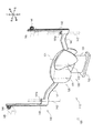
遊技盤6は、図3に示すように、遊技板10と、ガイドレール11と、センター役物12と、図柄表示装置13と、可変入賞装置14と、大入賞装置15と、アウト口16と、可動演出装置100等により構成される。
As shown in FIG. 3, the
遊技板10は、四隅が適宜に切り欠けられた略平板状に形成される部材である。遊技板10には、遊技盤6を構成する各種の遊技部品が取り付けられる。
The
ガイドレール11は、略円弧帯状に形成される部材である。ガイドレール11は、遊技板10に、前方へ向けて立ち上がり状に取り付けられる。ガイドレール11は、正面視で略円形状を形成するように配置される。なお、遊技板10においてガイドレール11によって略円形状に形成された内側の領域が、遊技球が転動する領域である遊技領域25として構成される。
The guide rail 11 is a member formed in a substantially arc belt shape. The guide rail 11 is attached to the
センター役物12は、その外観により遊技板10を装飾する部材である。センター役物12は正面視で略環状であって、その中央にセンター開口部27が前後方向に貫通して形成される。センター役物12は、遊技板10を前後方向に貫通するように当該遊技板10の中央から上部に渡って形成される孔に前方から挿入され、ボルト等によって取り付けられる。
The
図柄表示装置13は、前方を臨むように配設された液晶画面26に図柄や数字等の変動(図柄遊技)を表示するように構成される装置である。図柄表示装置13は、遊技板10の後方に配置される。より詳細には、図柄表示装置13の液晶画面26が、遊技板10に取り付けられたセンター役物12のセンター開口部27の後方に配置される。これによって、前方からセンター開口部27を介して液晶画面26に表示される図柄遊技を視認することができる。
The
可変入賞装置14は、所定の作動条件に応じて左右一対の可動片28が開閉作動し、始動入賞口14aに遊技球が入球(入賞)可能な開放状態と入球(入賞)不能な閉塞状態とに切り替え可能に構成される装置である。可変入賞装置14は、遊技領域25の左右中央部であってセンター役物12の下方に配置される。なお、可変入賞装置14は、前記開放状態において始動入賞口14aに遊技球が入球(入賞)すると図示せぬ賞球払出装置によって所定数の遊技球(賞球)が払い出されるように構成される。
The
大入賞装置15は、所定の大当たり抽選により大当たりが選択されると、大入賞口15aを開放して遊技球が入球(入賞)可能に構成される装置である。大入賞装置15は、遊技領域25の左右中央部であって可変入賞装置14の下方に配置される。なお、大入賞装置15は、開放した大入賞口15aに遊技球が入球すると図示せぬ賞球払出装置によって所定数の遊技球(賞球)が払い出されるように構成される。
The
アウト口16は、遊技領域25を転動する遊技球が、大入賞口15aや始動入賞口14a等の各入賞口に入球(入賞)しなかった場合に、最終的に流入する開口部である。アウト口16は、遊技領域25の最下部に配置される。なお、アウト口16に流入した遊技球は、遊技機1が設置されたパチンコホール等の遊技場側に回収される。
The out
次に、可動演出装置100の構成について詳細に説明する。
Next, the configuration of the
図3から図16までに示す可動演出装置100は、液晶画面26に表示される図柄遊技に応じて可動し、遊技者に視覚的な印象(インパクト)を与えるためのものである。可動演出装置100は、液晶画面26の下方に配置されるとともに、前後方向においてセンター役物12と液晶画面26との間、すなわちセンター役物12よりも後方であって液晶画面26よりも前方に配置される。可動演出装置100は、主として、可動演出体110と、駆動手段140と、ストッパ150と、により構成される。
The
図4から図10までに示す可動演出体110は、ボクシンググローブの形状を模した構造体であり、遊技者から視認可能となる位置(出現位置)又は視認不能となる位置(収容位置)に移動することにより、遊技者に視覚的な印象(インパクト)を与えるためのものである。可動演出体110は、主として上側可動体120と、下側可動体130と、により構成される。
The
図4、図5及び図7から図10までに示す上側可動体120は、本発明に係る第一装飾体の実施の一形態であり、ボクシンググローブのうち人差し指から小指までが収容される部分を模したものである。上側可動体120は、左右方向に長い板状の部材であり、その板面を前後方向に向けて配置される。上側可動体120の周囲(上下左右の端部)は、ボクシンググローブの形状を模した曲線状となるように形成される。上側可動体120は、主として肉薄部121と、肉厚部122と、により構成される。
The upper
肉薄部121は、本発明に係る基部の実施の一形態であり、上側可動体120の左右略中央部から右端部までを構成し、他の部分に比べて厚さ(前後方向幅)が薄い部分である。肉薄部121の背面の下端部には、後方に向かって突出するように突起部121aが形成される(図10参照)。
The
肉厚部122は、本発明に係る突出部の実施の一形態であり、上側可動体120の左右略中央部から左端部までを構成し、他の部分(肉薄部121)に比べて厚さが厚い部分である。肉厚部122の前端は、肉薄部121の前端よりも前側に位置するように立体的に形成される。
The
図4及び図6から図10までに示す下側可動体130は、本発明に係る第二装飾体の実施の一形態であり、ボクシンググローブのうち親指が収容される部分及び掌から手首までが収容される部分を模したものである。下側可動体130は、主として本体部131と、前壁部132と、溝部133と、により構成される。
The lower
本体部131は、ボクシンググローブのうち掌から手首までが収容される部分を模した部分である。本体部131は、上下方向に長い板状に形成され、その板面を前後方向に向けて配置される。本体部131の下部の周囲は手首の形状を模した略矩形状となるように形成され、本体部131の上部の周囲は掌の形状を模した曲線状となるように形成される。本体部131の前面の上端部近傍から上下略中央部までには、他の部分よりも後方に窪むように係合溝131aが形成される(図10参照)。
The
前壁部132は、ボクシンググローブのうち親指が収容される部分を模した部分である。前壁部132は、板状に形成され、その板面を前後方向に向けて本体部131の右端部の前方に配置される。前壁部132の下部は、本体部131の上下中央部分に一体的に固定される(図10参照)。前壁部132の周囲はボクシンググローブのうち親指が収容される部分を模した曲線状となるように形成される。
The
溝部133は、本体部131と前壁部132との間に形成される部分である。溝部133は、後方を本体部131に、前方を前壁部132に、下方を本体部131と前壁部132との連結部分に、それぞれ閉塞され、側面断面視において上方が開放したU字状になるように形成される。
The
図7から図10までに示すように、上述の如く構成された上側可動体120及び下側可動体130は、前方から見て互いに部分的に重複する状態で配置される。
より詳細には、上側可動体120は、下側可動体130の本体部131よりも前方に配置されるとともに、当該上側可動体120の肉薄部121が下側可動体130の溝部133に挿入される。このとき、上側可動体120の肉厚部122と下側可動体130の前壁部132との左右方向位置がずれている(肉厚部122は、前壁部132の左方に位置している)ため、当該肉厚部122と前壁部132とは干渉することがない。
また、このとき、上側可動体120の突起部121aは、下側可動体130の係合溝131a内に位置することになる(図10参照)。したがって、上側可動体120と下側可動体130とは、係合溝131aの上下幅内において相対的に上下方向に摺動可能となる。
As shown in FIGS. 7 to 10, the upper
More specifically, the upper
At this time, the
そして、上側可動体120及び下側可動体130において、上側可動体120の肉薄部121は、ボクシンググローブのうち、下側可動体130の前壁部132が対応する部分(ボクシンググローブの親指が収容される部分)よりも遊技者から遠くに位置すべき部分に対応づけられ、具体的には、ボクシンググローブの人差し指及び中指が収容される部分を模して形成される。また、上側可動体120の肉厚部122は、下側可動体130の本体部131が対応する部分(ボクシンググローブの掌部分)よりも遊技者の近くに位置すべき部分に対応づけられ、具体的には、ボクシンググローブの薬指及び小指が収容される部分を模して形成される。
なお、上側可動体120及び下側可動体130は、塗装したり、予め着色された材料を用いたりすることで、ボクシンググローブの色(例えば赤色や青色等)になるように形成される。
In the upper
The upper
図7に示す駆動手段140は、上側可動体120を上下方向に移動させるものである。駆動手段140は、主として支持部141・141と、案内軸142・142と、ラック143・143と、ピニオン144・144と、モータ145・145と、により構成される。
The driving means 140 shown in FIG. 7 moves the upper
支持部141・141は、上側可動体120を支持するものである。支持部141・141は、上側可動体120と一体的に形成され、当該上側可動体120の左右両端部から左右外側に向かってそれぞれ延設される。支持部141・141の外側端部には、当該支持部141・141を上下方向に貫通する貫通孔141a・141aがそれぞれ形成される。支持部141・141は、透過性を有する部材によって形成され、遊技者から視認し難くなるように構成される。
The
案内軸142・142は、支持部141・141を上下方向に案内するものである。案内軸142・142は、その長手方向を上下方向に向けた状態で、支持部141・141の貫通孔141a・141aにそれぞれ挿通され、遊技盤6に適宜固定される。
The
ラック143・143は、支持部141・141の外側端部から上方に向かってそれぞれ延設される。
The
ピニオン144・144は、ラック143・143の上端部近傍において、当該ラック143・143とそれぞれ噛合される。
The
モータ145・145は、上側可動体120を駆動させるための駆動源となるものである。モータ145・145は、ピニオン144・144の前方にそれぞれ配置され、当該モータ145・145の出力軸はピニオン144・144にそれぞれ固定される。モータ145・145は、遊技盤6に適宜固定される。
The
図7から図10までに示すストッパ150は、下側可動体130の下方への移動を規制するものである。ストッパ150は、矩形板状に形成され、その板面を上下方向に向けて下側可動体130の下方に配置される。ストッパ150は、遊技盤6に適宜固定される。
The
次に、図3及び図7から図10までを用いて、可動演出体110が収容位置にある場合について説明する。ここで、「収容位置」とは、可動演出体110がセンター役物12の下部よりも下方に下がって、当該センター役物12の背後に隠蔽される(遊技者側から視認不能とされる)位置(図3参照)をいうものとする。
Next, the case where the
収容位置は、上側可動体120が最も下方に位置している状態である。収容位置においては、下側可動体130も自重により下方に移動しようとするが、ストッパ150が当該下側可動体130の下端部に当接し、当該下側可動体130の下方への移動を規制するため、当該下側可動体130は所定位置(高さ)に保持される。これによって、上側可動体120と下側可動体130とは相対的に摺動(下側可動体130が上側可動体120に対して上方に摺動)し、可動演出体110の上下方向高さ(全長)は最も短くなるように短縮される。
The accommodation position is a state in which the upper
このように、可動演出体110が収容位置にある場合、当該可動演出体110の全長を最も短くした状態でセンター役物12の下部の背後に収容することができるため、当該可動演出体110を収容するために必要なスペースを小さくすることができる。
As described above, when the
次に、図3及び図11を用いて、可動演出体110が収容位置から後述する出現位置に移動する際の様子について説明する。
Next, a state when the
可動演出体110を収容位置から出現位置に移動させる場合、まずモータ145・145を駆動させ、ピニオン144・144を所定方向(右側のピニオン144は正面視時計回り、左側のピニオン144は正面視反時計回り)に回転させる。ピニオン144・144が回転すると、当該ピニオン144・144に噛合されたラック143・143が上方に移動する。ラック143・143が上方に移動すると、支持部141・141を介して上側可動体120も上方に移動する。この際、支持部141・141は案内軸142・142によって上下方向に案内されているため、上側可動体120を正確に上方に移動させることができる。
When moving the
図11に示すように、上側可動体120を上方に移動させると、下側可動体130は自重によりストッパ150に当接した状態に保持されるため、まずは上側可動体120と下側可動体130とが相対的に摺動(上側可動体120が下側可動体130に対して上方に摺動)し、当該上側可動体120と下側可動体130との重複量が減少して可動演出体110の上下方向高さ(全長)は伸長する。
As shown in FIG. 11, when the upper
上側可動体120が、下側可動体130に対して係合溝131aの上下幅分だけ相対的に摺動すると、上側可動体120の突起部121aが、下側可動体130の係合溝131aの上端部と係合し、下側可動体130が、上側可動体120に吊り下げ支持された状態となる。この状態からさらに上側可動体120を上方に移動させると、可動演出体110の全長は伸長することなく、当該上側可動体120とともに下側可動体130も上方に移動する。
これらの際、可動演出体110では、上側可動体120が上昇して突起部121aが下側可動体130の係合溝131aの上端部に係合するまでは、上側可動体120のみがセンター役物12の下部から出現する。そして、上側可動体120の突起部121aと下側可動体130の係合溝131aとが係合し、可動演出体110の全長が最大になった後、下側可動体130が徐々に出現し始める。このため、遊技者は、まず、上側可動体120のみを視認し、その後、可動演出体110が最大長となってボクシンググローブの装飾が完成した時点から上側可動体120及び下側可動体130の双方を視認し始めることになる。
When the upper
At this time, in the
このように、まず上側可動体120のみを上方に移動させ、可動演出体110の全長を伸長させた後に、下側可動体130を上方に移動させることで、遊技者に対し、可動演出体110が短縮している状態を視認させることがなく、あたかも、一の演出用装飾(ボクシンググローブ)をなしたものが徐々に現れ出るかのような印象を与えることができる。
In this way, first, only the upper
可動演出体110がセンター役物12の下部の背後から上方に出現し、ボクシンググローブを模した形状が遊技者側から視認可能となる位置に来たときに、モータ145・145の駆動を停止し、当該可動演出体110を当該位置に保持する(図12参照)。この位置を「出現位置」とする。なお、この際、上側可動体120を支持している支持部141・141は透過性を有するため、遊技者は当該支持部141・141を介して液晶画面26を視認することができる。
When the
次に、図12から図16までを用いて、可動演出体110が出現位置にある場合について説明する。
Next, the case where the
出現位置は、上側可動体120が最も上方に位置している状態である。出現位置においては、前述の如く下側可動体130が自重により下方に移動するため、上側可動体120と下側可動体130とは相対的に摺動(下側可動体130が上側可動体120に対して下方に摺動)し、可動演出体110の上下方向高さ(全長)は最も長くなるように伸長される。
The appearance position is a state where the upper
上記の如く可動演出体110が伸長された場合、上側可動体120及び下側可動体130が一体となって一の演出用装飾、すなわちボクシンググローブを構成する。詳細には、下側可動体130の本体部131の下部がボクシンググローブの手首部分を、本体部131の上部がボクシンググローブの掌部分を、前壁部132がボクシンググローブの親指部分を、上側可動体120がボクシンググローブの人差し指から小指までの部分を、それぞれ模して、全体としてボクシンググローブの形状を模すことになる。
When the
また、出現位置における可動演出体110は、遊技者側(前方)から見て上側可動体120の肉厚部122及び下側可動体130の前壁部132が手前側(前方)に位置し、上側可動体120の肉薄部121及び下側可動体130の本体部131が奥側(後方)に位置するため、複雑な前後配置を実現することができる。これによって、実際のボクシンググローブに近い立体感を実現することができる(図13参照)。
In addition, the
次に、図17を用いて、可動演出体110が出現位置から収容位置に移動する際の様子について説明する。
Next, a state when the
可動演出体110を出現位置から収容位置に移動させる場合、モータ145・145(図7参照)を前記(収容位置から出現位置に移動させる場合)とは逆方向に駆動させ、上側可動体120を下方に移動させる。上側可動体120を下方に移動させると、当該上側可動体120とともに下側可動体130も下方に移動する。この際、上側可動体120と下側可動体130とは相対的に摺動することはない。
When moving the
下側可動体130の下端がストッパ150に当接すると、当該下側可動体130はそれ以上下方に移動することができない。この状態で上側可動体120をさらに下方に移動させると、上側可動体120と下側可動体130とが相対的に摺動(上側可動体120が下側可動体130に対して下方に摺動)し、当該上側可動体120と下側可動体130との重複量が増加して可動演出体110の上下方向高さ(全長)は短縮する。
When the lower end of the lower
このように、まず可動演出体110の全長を変化させることなく下方に移動させ、その後当該可動演出体110の全長を短縮させることで、遊技者は、可動演出体110が短縮している状態を視認することがない。
Thus, by first moving the
上側可動体120が最も下方に位置したときにモータ145・145の駆動を停止させることで、再び可動演出体110を収容位置に保持することができる。
By stopping the driving of the
以上の如く、本実施形態に係る遊技機1の可動演出装置100は、
上下方向(所定の方向)に往復移動自在に支持される上側可動体120、及び前方から見て上側可動体120と部分的に重複する状態で配置される下側可動体130を有する可動演出体110と、
上側可動体120を移動させる駆動手段140と、
を備え、
上側可動体120を上方(第一方向)に向けて移動させると、可動演出体110の上側可動体120と下側可動体130との重複量が減少して当該可動演出体110が伸長し、かつ上側可動体120及び下側可動体130が一体となって一の演出用装飾を構成する一方、
その状態から上側可動体120を前記第一方向と反対の下方(第二方向)に向けて移動させると、上側可動体120と下側可動体130との重複量が増加して可動演出体110が短縮する遊技機1の可動演出装置100において、
上側可動体120は、
肉薄部121と、
前端が肉薄部121の前端よりも前側に位置する肉厚部122と、
を備え、
下側可動体130は、
上側可動体120の背面側に配置される本体部131と、
本体部131の前方に配置される前壁部132と、
本体部131及び前壁部132の間に形成され、挿入量を可変に肉薄部121が挿入される溝部133と、
を備え、
前記演出用装飾を分割した複数の部分装飾を肉薄部121、肉厚部122、本体部131及び前壁部132の各々に割り当て、肉薄部121の溝部133への挿入量を変化させて可動演出体110を伸長し、肉厚部122及び前壁部132が肉薄部121及び本体部131よりも前側に位置して前記演出用装飾を構成するものである。
As described above, the
A movable effect body having an upper
Driving means 140 for moving the upper
With
When the upper
When the upper
The upper
A
A
With
The lower
A
A
A
With
A plurality of partial decorations obtained by dividing the effect decoration are assigned to each of the
このように構成することにより、肉厚部122及び前壁部132を前側に、肉薄部121及び本体部131を後側にそれぞれ位置させることで、可動演出体110を複雑な立体的形状で構成することができる。そして、演出用装飾を分割した複数の部分装飾を肉薄部121、肉厚部122、本体部131及び前壁部132の各々に割り当て、可動演出体110を伸長させたときに、肉薄部121、肉厚部122、本体部131及び前壁部132によって演出用装飾を構成するため、目的の演出用装飾に合わせて肉厚部122、肉薄部121、本体部131及び前壁部132の位置や大きさを定めることで、自然な立体感を実現することが可能になる。
また、可動演出体110を遊技者が視認できる位置に出現させるときは、当該可動演出体110の全長を長くして当該遊技者に与える印象(インパクト)を高めつつ、当該可動演出体110を遊技者が視認できない位置に収容するときは、当該可動演出体110の全長を短くして当該可動演出体110を収容するために必要なスペースを小さくすることができる。
By configuring in this way, the
Further, when the
また、本実施形態に係る遊技機1の可動演出装置100は、
可動演出体110が収容位置から出現位置に移動する場合、
上側可動体120が遊技者側から視認可能な位置に移動すると共に上側可動体120と下側可動体130とが相対的に移動し、その後可動演出体110の全長が最大まで伸長した後で、下側可動体130が遊技者側から視認可能な位置に移動し、
可動演出体110が出現位置から収容位置に移動する場合、
全長が最大まで伸長した状態の可動演出体110が遊技者側から視認不能な位置に移動した後で、上側可動体120と下側可動体130とが相対的に移動して当該可動演出体110の全長が最小まで短縮するものである。
In addition, the
When the
After the upper
When the
After the
このように構成することにより、遊技者に対し、可動演出体110が短縮した状態を視認させることがなく、常に一の演出用装飾(ボクシンググローブ)を構成した状態を視認させることができ、見栄えに優れた可動役物演出を提供することが可能になる。
By configuring in this way, the player can be made to visually recognize the state in which the one effect decoration (boxing glove) is configured without visually recognizing the shortened state of the
なお、本実施形態においては、上側可動体120の基部を肉薄部121によって構成し、突出部を肉厚部122によって構成したが、厚さが一定の板状部材を基部及び突出部に合わせた形状とすることにより、基部及び突出部を構成しても良い。
また、本実施形態においては、本体部131の前面に係合溝131aを形成するものとした(図10参照)が、当該係合溝131aは本体部131の前面と後面とを貫通する貫通孔として形成することも可能である。
また、本実施形態においては、上側可動体120に突起部121aを、下側可動体130に係合溝131aを、それぞれ設ける構成としたが、本発明はこれに限るものではなく、上側可動体120に係合溝を、下側可動体130に突起部を、それぞれ設ける構成とすることも可能である。
また、本実施形態においては、上側可動体120の肉薄部121及び肉厚部122、並びに下側可動体130の本体部131及び前壁部132を、それぞれ一体的に構成するものとしたが、本発明はこれに限るものではなく、それぞれ別部材を組み合わせて(別体として)構成することも可能である。
また、本実施形態においては、上側可動体120及び支持部141・141を一体的に構成するものとしたが、本発明はこれに限るものではなく、別部材を組み合わせて(別体として)構成することも可能である。
また、本実施形態に係る上側可動体120及び下側可動体130は、いずれも概ね板状の部材により構成するものとしたが、本発明はこれに限るものではなく、当該上側可動体120及び下側可動体130を収容するスペースが確保できるのであれば、より立体的な形状の部材(例えば、直方体状、円柱状等)により構成することも可能である。
また、本実施形態においては、可動演出体110は一の演出用装飾としてボクシンググローブの形状を模すものとしたが、本発明はこれに限るものではなく、他の装飾(例えば、他の物品の形状、記号又は文字等を模したもの)であっても良い。
また、駆動手段140の構成は本実施形態に係るものに限らず、上側可動体120を上下方向に移動させることができる構造であれば良い。
また、ストッパ150の構成は本実施形態に係るものに限らず、下側可動体130の移動を所定の位置で規制することができるものであれば良い。
In the present embodiment, the base portion of the upper
In the present embodiment, the engaging
In the present embodiment, the
Further, in the present embodiment, the
In the present embodiment, the upper
In addition, the upper
Further, in the present embodiment, the
The configuration of the
Further, the configuration of the
また、本実施形態においては、上側可動体120及び下側可動体130を上下方向に往復移動自在とし、可動演出体110が下方に位置している状態で隠蔽し、上方に移動させることで出現させる構成としたが、本発明はこれに限るものではない。すなわち、上側可動体120及び下側可動体130は左右方向や斜め方向に往復移動自在とすることも可能であり、左右方向、下方又は斜め方向に移動させることで出現させる構成とすることも可能である。
また、本実施形態においては、上側可動体120が上下方向に往復移動すると、それに伴って下側可動体130が吊り下げ支持されて当該下側可動体130も上下方向に往復移動する構成としたが、本発明はこれに限るものではない。すなわち、上側可動体120だけが上下方向に往復移動し、下側可動体130は所定の位置において移動することなく保持される構成とすることも可能である。
Further, in the present embodiment, the upper
Further, in the present embodiment, when the upper
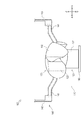
また、本実施形態に係る可動演出装置100の上下方向を逆にして、可動演出体110を下方に向かって出現させる構成とすることも可能である。この場合、図18に示すように、下側可動体130を常時上方に付勢するためのバネ160・160を設けることが好ましい。
Moreover, it is also possible to make it the structure which makes the up-down direction of the movable production |
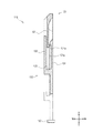
また、本実施形態に係る可動演出装置100は、上側可動体120が肉薄部121(突起部121a)及び肉厚部122を具備し、下側可動体130が本体部131(係合溝131a)、前壁部132及び溝部133を具備するものとしたが、本発明はこれに限るものではない。
すなわち、図19に示す可動演出体210のように、上側可動体220が本体部221(係合溝221a)、前壁部222及び溝部223を具備し、下側可動体230が肉薄部231(突起部231a)及び肉厚部(不図示)を具備する構成とすることも可能である。
In the
That is, like the
1:遊技機,100:可動演出装置,110:可動演出体,120:上側可動体,121:肉薄部,122:肉厚部,130:下側可動体,131:本体部,132:前壁部,133:溝部,140:駆動手段 1: gaming machine, 100: movable production device, 110: movable production body, 120: upper movable body, 121: thin part, 122: thick part, 130: lower movable body, 131: main body part, 132: front wall Part, 133: groove part, 140: driving means
Claims (1)
前記第一装飾体を移動させる駆動手段と、
を備え、
前記第一装飾体を第一方向に向けて移動させると、前記可動演出体の前記第一装飾体と前記第二装飾体との重複量が減少して当該可動演出体が伸長し、かつ前記第一装飾体及び前記第二装飾体が一体となって一の演出用装飾を構成する一方、
その状態から前記第一装飾体を前記第一方向と反対の第二方向に向けて移動させると、前記第一装飾体と前記第二装飾体との重複量が増加して前記可動演出体が短縮する遊技機の可動演出装置において、
前記第一装飾体及び前記第二装飾体のいずれか一方は、
基部と、
前端が前記基部の前端よりも前側に位置する突出部と、
を備え、
前記第一装飾体及び前記第二装飾体のいずれか他方は、
前記第一装飾体及び前記第二装飾体のいずれか一方の背面側に配置される本体部と、
前記本体部の前方に配置される前壁部と、
前記本体部及び前記前壁部の間に形成され、挿入量を可変に前記基部が挿入される溝部と、
を備え、
前記演出用装飾を分割した複数の部分装飾を前記基部、突出部、本体部及び前壁部の各々に割り当て、前記基部の前記溝部への挿入量を変化させて前記可動演出体を伸長し、前記突出部及び前壁部が前記基部及び本体部よりも前側に位置して前記演出用装飾を構成する、
遊技機の可動演出装置。 A movable decorative body having a first decorative body that is supported so as to freely reciprocate in a predetermined direction, and a second decorative body that is arranged in a state of partially overlapping the first decorative body as viewed from the front;
Drive means for moving the first decorative body;
With
When the first decorative body is moved in the first direction, the amount of overlap between the first decorative body and the second decorative body of the movable rendering body is reduced and the movable rendering body is extended, and While the first decorative body and the second decorative body together constitute one production decoration,
When the first decorative body is moved from the state toward the second direction opposite to the first direction, the amount of overlap between the first decorative body and the second decorative body is increased, and the movable effect body is In the movable directing device of the gaming machine to shorten,
Either the first decorative body or the second decorative body is
The base,
A protrusion having a front end positioned on the front side of the front end of the base,
With
Either one of the first decorative body and the second decorative body is:
A main body disposed on the back side of either the first decorative body or the second decorative body;
A front wall portion disposed in front of the main body portion;
A groove portion formed between the main body portion and the front wall portion, in which the base portion is inserted with a variable insertion amount;
With
A plurality of partial decorations obtained by dividing the effect decoration are assigned to each of the base part, the projecting part, the main body part and the front wall part, and the movable effector is extended by changing the amount of insertion of the base part into the groove part, The projecting part and the front wall part are located on the front side of the base part and the main body part to constitute the decoration for presentation.
A movable production device for gaming machines.
Priority Applications (1)
| Application Number | Priority Date | Filing Date | Title |
|---|---|---|---|
| JP2011118528A JP5440552B2 (en) | 2011-05-26 | 2011-05-26 | Movable direction device for gaming machine |
Applications Claiming Priority (1)
| Application Number | Priority Date | Filing Date | Title |
|---|---|---|---|
| JP2011118528A JP5440552B2 (en) | 2011-05-26 | 2011-05-26 | Movable direction device for gaming machine |
Publications (2)
| Publication Number | Publication Date |
|---|---|
| JP2012245123A JP2012245123A (en) | 2012-12-13 |
| JP5440552B2 true JP5440552B2 (en) | 2014-03-12 |
Family
ID=47466162
Family Applications (1)
| Application Number | Title | Priority Date | Filing Date |
|---|---|---|---|
| JP2011118528A Expired - Fee Related JP5440552B2 (en) | 2011-05-26 | 2011-05-26 | Movable direction device for gaming machine |
Country Status (1)
| Country | Link |
|---|---|
| JP (1) | JP5440552B2 (en) |
Families Citing this family (3)
| Publication number | Priority date | Publication date | Assignee | Title |
|---|---|---|---|---|
| JP6873545B2 (en) * | 2017-03-14 | 2021-05-19 | 株式会社ユニバーサルエンターテインメント | Pachinko machine |
| JP6610967B2 (en) * | 2017-10-05 | 2019-11-27 | 豊丸産業株式会社 | Rendering device and gaming machine equipped with the rendering device |
| JP7042476B2 (en) * | 2017-11-03 | 2022-03-28 | 株式会社サンセイアールアンドディ | Pachinko machine |
Family Cites Families (4)
| Publication number | Priority date | Publication date | Assignee | Title |
|---|---|---|---|---|
| JP4568855B2 (en) * | 2004-12-03 | 2010-10-27 | 株式会社大一商会 | Game machine |
| JP4828872B2 (en) * | 2005-07-05 | 2011-11-30 | 株式会社平和 | Game machine equipment |
| JP4313349B2 (en) * | 2005-09-01 | 2009-08-12 | 株式会社藤商事 | Game machine |
| JP2007235812A (en) * | 2006-03-03 | 2007-09-13 | Nec Corp | Position information interlocking system and position information interlocking method |
-
2011
- 2011-05-26 JP JP2011118528A patent/JP5440552B2/en not_active Expired - Fee Related
Also Published As
| Publication number | Publication date |
|---|---|
| JP2012245123A (en) | 2012-12-13 |
Similar Documents
| Publication | Publication Date | Title |
|---|---|---|
| JP2014083111A (en) | Movable performance device of game machine | |
| JP2015006322A (en) | Game machine | |
| JP2010273994A (en) | Pachinko game machine | |
| JP2014018573A (en) | Pachinko game machine | |
| JP5440552B2 (en) | Movable direction device for gaming machine | |
| JP2015042197A (en) | Pachinko game machine | |
| JP2008229056A (en) | Game production body, game machine, and game production method | |
| JP2013215411A (en) | Pachinko game machine | |
| JP5673488B2 (en) | Movable direction device for gaming machine | |
| JP5505554B1 (en) | Movable accessory device for gaming machines | |
| JP2014230598A (en) | Game machine | |
| JP5757045B2 (en) | Game machine | |
| JP6006018B2 (en) | Game machine | |
| JP2013094465A (en) | Pachinko game machine | |
| JP5477337B2 (en) | Movable direction device for gaming machine | |
| JP5849262B2 (en) | Game machine | |
| JP5963911B2 (en) | Bullet ball machine | |
| JP5748810B2 (en) | Bullet ball machine | |
| JP5565535B1 (en) | Movable direction device for gaming machine | |
| JP2015057221A (en) | Pachinko game machine | |
| JP5477332B2 (en) | Game machine | |
| JP6696074B2 (en) | Amusement machine | |
| JP7141676B2 (en) | game machine | |
| JP6093075B2 (en) | Bullet ball machine | |
| JP6372763B2 (en) | Game machine |
Legal Events
| Date | Code | Title | Description |
|---|---|---|---|
| A621 | Written request for application examination |
Free format text: JAPANESE INTERMEDIATE CODE: A621 Effective date: 20130417 |
|
| TRDD | Decision of grant or rejection written | ||
| A01 | Written decision to grant a patent or to grant a registration (utility model) |
Free format text: JAPANESE INTERMEDIATE CODE: A01 Effective date: 20131119 |
|
| A977 | Report on retrieval |
Free format text: JAPANESE INTERMEDIATE CODE: A971007 Effective date: 20131122 |
|
| A61 | First payment of annual fees (during grant procedure) |
Free format text: JAPANESE INTERMEDIATE CODE: A61 Effective date: 20131202 |
|
| R150 | Certificate of patent or registration of utility model |
Free format text: JAPANESE INTERMEDIATE CODE: R150 |
|
| LAPS | Cancellation because of no payment of annual fees |