JP5421856B2 - Game machine - Google Patents
Game machine Download PDFInfo
- Publication number
- JP5421856B2 JP5421856B2 JP2010114710A JP2010114710A JP5421856B2 JP 5421856 B2 JP5421856 B2 JP 5421856B2 JP 2010114710 A JP2010114710 A JP 2010114710A JP 2010114710 A JP2010114710 A JP 2010114710A JP 5421856 B2 JP5421856 B2 JP 5421856B2
- Authority
- JP
- Japan
- Prior art keywords
- state
- big hit
- display
- special symbol
- symbol
- Prior art date
- Legal status (The legal status is an assumption and is not a legal conclusion. Google has not performed a legal analysis and makes no representation as to the accuracy of the status listed.)
- Expired - Fee Related
Links
Images


Description
本発明は、各々を識別可能な複数種類の識別情報の可変表示を開始し、表示結果を導出表示する可変表示部を備え、該可変表示部に特定表示結果が導出表示されたときに遊技者にとって有利な特定遊技状態に制御するとともに、特別条件が成立したことにもとづいて通常遊技状態であるときに比べて識別情報の可変表示の表示結果が特定表示結果となる確率が向上した高確率状態に制御する遊技機に関する。 The present invention includes a variable display unit that starts variable display of a plurality of types of identification information that can identify each, and derives and displays a display result. When a specific display result is derived and displayed on the variable display unit, the player A high probability state that is controlled to a specific gaming state advantageous to the user and that the probability that the display result of the variable display of the identification information becomes the specific display result is improved compared to the normal gaming state based on the establishment of the special condition It relates to a gaming machine to be controlled.
遊技機として、遊技球などの遊技媒体を発射装置によって遊技領域に発射し、遊技領域に設けられている入賞口などの入賞領域に遊技媒体が入賞すると、所定個の賞球が遊技者に払い出されるものがある。さらに、識別情報を可変表示(「変動」ともいう。)可能な可変表示装置が設けられ、可変表示装置において識別情報の可変表示の表示結果が特定表示結果となった場合に遊技者にとって有利な特定遊技状態に制御可能になるように構成されたものがある。 As a gaming machine, a game medium such as a game ball is launched into a game area by a launching device, and when a game medium wins a prize area such as a prize opening provided in the game area, a predetermined number of prize balls are paid out to the player. There is something to be done. Furthermore, a variable display device capable of variably displaying the identification information (also referred to as “fluctuation”) is provided, which is advantageous to the player when the display result of the variable display of the identification information becomes the specific display result in the variable display device. Some are configured to be controllable to a specific gaming state.
特定遊技状態とは、所定の遊技価値が付与された遊技者にとって有利な状態を意味する。具体的には、特定遊技状態は、例えば特別可変入賞装置の状態を遊技媒体が入賞しやすい遊技者にとって有利な状態(大当り遊技状態)、遊技者にとって有利な状態になるための権利が発生した状態、景品遊技媒体払出の条件が成立しやすくなる状態などの所定の遊技価値が付与された状態である。 The specific game state means a state advantageous for a player who is given a predetermined game value. Specifically, the specific game state has a right to be in an advantageous state for a player who easily wins a game medium (a big hit game state), for example, a state of a special variable prize-winning device, or a state advantageous for a player. A state in which a predetermined game value such as a state or a state in which a condition for giving out premium game media is easily established is given.
そのような遊技機では、識別情報としての図柄を表示する可変表示装置の表示結果があらかじめ定められた特定の表示態様の組合せ(特定表示結果)になることを、通常、「大当り」という。大当りが発生すると、例えば、大入賞口が所定回数開放して遊技媒体が入賞しやすい特定遊技状態(大当り遊技状態)に移行する。そして、各開放期間において、所定個(例えば10個)の大入賞口への入賞があると大入賞口は閉成する。各開放について開放時間(例えば29秒)が決められ、入賞数が所定個に達しなくても開放時間が経過すると大入賞口は閉成する。 In such a gaming machine, the fact that the display result of the variable display device that displays the symbol as identification information is a combination of specific display modes (specific display result) determined in advance is generally referred to as “big hit”. When a big win occurs, for example, the big winning opening is opened a predetermined number of times, and the game medium shifts to a specific gaming state (a big winning gaming state) where the game medium is easy to win. And in each open period, if there is a prize for a predetermined number (for example, 10) of the big prize opening, the big prize opening is closed. An opening time (for example, 29 seconds) is determined for each opening, and even if the number of winnings does not reach a predetermined number, the winning opening is closed when the opening time elapses.
また、遊技機には、可変表示装置において識別情報の可変表示の表示結果が特定表示結果のうちの特別な特定表示結果(特別表示結果)となるなどの特別の条件が成立すると、以後、大当りが発生する確率が高くなる特別遊技状態(例えば、大当りと判定される割合自体が高められた確変状態(高確率状態)。又は、図柄の変動時間を短縮することにより結果的に大当りが発生しやすくなる時短状態でもよい。)に移行するように構成されたものもある。 In addition, if a special condition such as a display result of variable display of identification information becomes a special specific display result (special display result) of the specific display results in the variable display device, the jackpot is subsequently obtained. Special gaming state where the probability of occurrence of the game is high (for example, the probability variation state (high probability state) in which the rate determined to be a big hit itself is increased), or a big hit occurs as a result of shortening the symbol variation time. Some may be configured to shift to a short time state.
また、そのような遊技機では、遊技状態が確変状態(高確率状態)に制御されていることを報知しないように構成されたものがある(例えば、特許文献1参照)。特許文献1に記載された遊技機では、確変状態であるか通常状態であるかの報知を、電源投入時を除き行わないようにし、現在の遊技状態が確変状態であるか否かを遊技者に認識されないようにしている。また、特許文献1には、遊技機への電源投入時に遊技状態が復旧されるときに、確変状態に復旧するときには、「確変状態復旧!」などと表示して確変状態に復旧した旨の確変状態復旧報知することが記載されている。
In addition, some of such gaming machines are configured not to notify that the gaming state is controlled to a probable change state (high probability state) (see, for example, Patent Document 1). In the gaming machine described in
しかし、特許文献1に記載された遊技機では、遊技店の開店時などに店内の各遊技機を初期化して起動する(例えば、前日に確変状態で終了したような場合でも、確変状態などの遊技状態を全てリセットして起動する)場合に、各遊技機が正常に初期化されたか否かを1台1台の遊技機を実際に確認して行わなければならない(例えば、確変状態復旧報知がなされていないことを1台1台確認しなければならない)。そのため、遊技店内の各遊技機を初期化して起動する場合の確認作業が煩雑となり、遊技店員の作業負担が増加してしまう。
However, in the gaming machine described in
そこで、本発明は、確変状態(高確率状態)であることを報知しないように構成した遊技機において、遊技機の初期化を行う場合の作業負担を軽減することができるようにすることを目的とする。 In view of the above, an object of the present invention is to reduce the work load in the case of initialization of a gaming machine in a gaming machine configured not to notify that it is in a probability variation state (high probability state). And
本発明による遊技機は、各々を識別可能な複数種類の識別情報(例えば、第1特別図柄、第2特別図柄)の可変表示を開始し、表示結果を導出表示する可変表示手段(例えば、第1特別図柄表示器8a、第2特別図柄表示器8b)を備え、該可変表示手段に特定表示結果(例えば、大当り図柄)が導出表示されたときに遊技者にとって有利な特定遊技状態(例えば、大当り遊技状態)に制御するとともに、特別条件が成立したこと(例えば、確変大当りや、突然確変大当りA、突然確変大当りBと決定されたこと)にもとづいて通常遊技状態であるときに比べて識別情報の可変表示の表示結果が特定表示結果となる確率が向上した高確率状態(例えば、確変状態)に制御する遊技機であって、遊技者によって操作可能な操作手段(例えば、スティックコントローラ122)と、制御を行う際に発生する変動データとして、少なくとも高確率状態に制御されていることを示す高確率状態中情報(例えば、確変フラグ)を含むデータを記憶する変動データ記憶手段(例えば、バックアップRAM)と、遊技機への電力供給が停止していても変動データ記憶手段の記憶内容を所定期間保持させることが可能な記憶内容保持手段(例えば、バックアップ電源としてのコンデンサ)と、特定遊技状態とするか否かと、特別条件を成立させるか否かとを、表示結果の導出表示以前に決定する事前決定手段(例えば、遊技制御用マイクロコンピュータ560におけるステップS61,S73を実行する部分)と、電力供給が開始されたときに、変動データ記憶手段に高確率状態中情報が記憶されていることにもとづいて、高確率状態に制御されていることを示す高確率状態中信号(例えば、高確中信号)を、遊技機の外部に出力する高確率状態中信号外部出力手段(例えば、遊技制御用マイクロコンピュータ560におけるステップS1075〜S1077を実行する部分)と、演出情報(例えば、キャラクタA〜C)を用いて実行される特定演出(例えば、バトル演出)の演出態様を、第1演出態様(例えば、バトル演出において味方のキャラクタがバトルに勝利する態様)または第2演出態様(例えば、バトル演出において味方のキャラクタがバトルに敗北する態様)のいずれとするかを決定する特定演出態様決定手段(例えば、演出制御用マイクロコンピュータ100におけるステップS8110を実行する部分)と、操作手段による操作に従って、特定演出に用いる演出情報を、複数種類の演出情報のうちから選択する演出情報選択手段(例えば、演出制御用マイクロコンピュータ100におけるステップS8111〜S8116を実行する部分)と、特定演出態様決定手段が決定した演出態様にもとづいて、演出情報選択手段が選択した演出情報を用いて、特定演出を実行する特定演出実行手段(例えば、演出制御用マイクロコンピュータ100において、ステップS8118を実行した後、次回以降のタイマ割込でステップS8105を実行する部分)と、高確率状態であるか否かにかかわらず共通演出(例えば、確変状態か否かにかかわらず共通の背景色(例えば、黄色)を表示)を実行する共通演出実行手段(例えば、演出制御用マイクロコンピュータ100におけるステップS673,S678を実行する部分)と、を備え、高確率状態中信号外部出力手段は、電力供給が開始された後の所定条件が成立(例えば、最初の大当りが発生)するまで高確率状態中信号の出力を継続し、所定条件が成立した後には、変動データ記憶手段に高確率状態中情報が記憶されている場合であっても高確率状態中信号の出力を禁止し(例えば、遊技制御用マイクロコンピュータ560におけるステップS136を実行する部分)、共通演出実行手段は、第2演出態様で特定演出が実行されたことにもとづいて、共通演出を実行し(例えば、演出制御用マイクロコンピュータ100は、ステップS872でNと判定したときにステップS874を実行して共通演出フラグをセットする)、特定演出態様決定手段は、事前決定手段によって特別条件を成立させないと決定されたときには、特定演出の演出態様として第2演出態様を決定し、事前決定手段によって特別条件を成立させると決定されたときには、演出情報選択手段が選択した演出情報に応じて異なる割合で、特定演出の演出態様として第1演出態様または第2演出態様のいずれかを決定する(例えば、演出制御用マイクロコンピュータ100は、ステップS6003,S6005,S6006で選択したバトル演出設定テーブルを用いてステップS6007を実行し、図62に示すように、キャラクタA〜Cに応じて異なる割合でバトル演出パターンを決定する)ことを特徴とする。そのような構成により、ホール側で高確率状態中信号の出力の有無を一括して確認することを可能とし、遊技機の初期化が行われたか否かを1台1台確認する手間を省くことが可能となる。従って、高確率状態であることを報知しないように構成した遊技機において、遊技機の初期化を行う場合の作業負担を軽減することができる。また、高確率状態に制御される場合に、遊技者の操作によって、第1演出態様で特定演出が実行される場合と、第2演出態様で特定演出が実行された後に共通演出が実行される場合とを設けることができる。そのため、同じ遊技状態であっても遊技者の操作によって演出状態を変化させることができ、遊技者の嗜好に合わせた演出を実現できるとともに、遊技に対する興趣を向上させることができる。
操作に応じて操作信号を出力する初期化操作手段と、電力供給が開始されたときに、初期化操作手段からの操作信号が入力されている場合に、変動データ記憶手段の記憶内容を初期化する初期化処理を実行する初期化処理実行手段と、所定のエラーが発生しているか否かを判定するエラー判定手段と、少なくとも、初期化処理実行手段によって初期化処理が実行されたこと、およびエラー判定手段によって所定のエラーが発生していると判定されたことを含む所定の信号出力条件が成立したことにもとづいて、遊技機の外部に所定の外部出力信号を出力する外部出力手段と、を備え、外部出力手段は、初期化処理実行手段によって初期化処理が実行されたときとエラー判定手段によって所定のエラーが発生していると判定されたときとで、高確率状態中信号を出力する出力端子とは別に遊技機に設けられた共通の出力端子から所定の外部出力信号を出力し、所定の外部出力信号を出力しているときに新たに所定の信号出力条件が成立した場合には、所定の外部出力信号を出力する出力時間を延長するように構成されていてもよい。
The gaming machine according to the present invention starts variable display of a plurality of types of identification information (for example, the first special symbol and the second special symbol) that can identify each, and variable display means (for example, first display) that derives and displays the display result. 1
Initializing operation means for outputting an operation signal in response to an operation, and when the operation signal is input from the initialization operation means when power supply is started, the stored contents of the fluctuation data storage means are initialized. Initialization processing execution means for executing initialization processing, error determination means for determining whether or not a predetermined error has occurred, and at least initialization processing has been executed by the initialization processing execution means, and An external output means for outputting a predetermined external output signal to the outside of the gaming machine based on the establishment of a predetermined signal output condition including that it is determined by the error determination means that a predetermined error has occurred; The external output means is high when the initialization process is executed by the initialization process execution means and when the predetermined error is determined by the error determination means. A predetermined external output signal is output from a common output terminal provided in the gaming machine separately from the output terminal that outputs a signal during the rate state, and a new predetermined signal output is performed when the predetermined external output signal is output When the condition is satisfied, the output time for outputting a predetermined external output signal may be extended.
遊技機は、事前決定手段の決定結果にもとづいて、高確率状態に制御する高確率状態制御手段(例えば、遊技制御用マイクロコンピュータ560におけるステップS178を実行する部分)と、事前決定手段の決定結果にもとづいて、始動領域を遊技媒体が通過しやすい状態となる頻度を高めた高頻度状態(例えば、高ベース状態)に制御する高頻度状態制御手段(例えば、遊技制御用マイクロコンピュータ560におけるステップS167,S170,S174,S175,S177を実行する部分)と、高確率状態に制御されているとともに高頻度状態に制御されているときに、識別情報の可変表示時間を短縮した時間短縮状態(例えば、時短状態)に制御する時間短縮状態制御手段(例えば、遊技制御用マイクロコンピュータ560におけるステップS167,S170,S174,S175,S177を実行する部分)と、を備え、事前決定手段は、特定遊技状態として、所定の遊技価値を付与する第1特定遊技状態(例えば、通常大当り、確変大当り)、または該第1特定遊技状態よりも低い遊技価値を付与する第2特定遊技状態(例えば、突然確変大当りA、突然確変大当りB、突然時短大当り)を含む複数種類の特定遊技状態のいずれとするかを、表示結果の導出表示以前に決定し、時間短縮状態制御手段は、時間短縮状態として、第1時間短縮状態(例えば、第1時短状態)、または該第1時間短縮状態よりもさらに識別情報の可変表示時間を短縮した第2時間短縮状態(例えば、第2時短状態)のいずれかに制御可能であり、第1時間短縮状態に制御しているときに、事前決定手段によって第2特定遊技状態とすると決定されたことにもとづいて、高い割合で第2時間短縮状態に制御する(例えば、遊技制御用マイクロコンピュータ560は、ステップS173でYであればステップS174で第2時短フラグをセットして第2時短状態に制御することによって、第2時短状態に制御される割合を高める)ように構成されていてもよい。そのような構成によれば、第1時間短縮状態で第2特定遊技状態となったときに第2時間短縮状態に移行される割合を高めることによって、遊技価値の低い第2特定遊技状態が発生した場合の遊技者の失望感を極力防止することができる。
The gaming machine has a high-probability state control means for controlling to a high-probability state based on the determination result of the prior-decision means (for example, the part executing step S178 in the gaming control microcomputer 560), and the determination result of the prior-decision means Based on the high-frequency state control means (for example, step S167 in the game control microcomputer 560) that controls the high-frequency state (for example, the high base state) in which the frequency at which the game medium easily passes through the start area is increased. , S 170, S 174,
可変表示部は、各々を識別可能な複数種類の第1の識別情報(例えば、第1特別図柄)の可変表示を開始し、表示結果を導出表示する第1の可変表示部(例えば、第1特別図柄表示器8a)と、各々を識別可能な複数種類の第2の識別情報(例えば、第2特別図柄)の可変表示を開始し、表示結果を導出表示する第2の可変表示部(例えば、第2特別図柄表示器8b)と、を有し、事前決定手段の決定結果にもとづいて、高確率状態に制御する高確率状態制御手段(例えば、遊技制御用マイクロコンピュータ560におけるステップS178を実行する部分)と、事前決定手段の決定結果にもとづいて、始動領域を遊技媒体が通過しやすい状態となる頻度を高めた高頻度状態(例えば、高ベース状態)に制御する高頻度状態制御手段(例えば、遊技制御用マイクロコンピュータ560におけるステップS167,S170,S174,S175,S177を実行する部分)と、高確率状態に制御されているとともに高頻度状態に制御されているときに、第1の識別情報および第2の識別情報の可変表示時間を短縮した時間短縮状態(例えば、時短状態)に制御する時間短縮状態制御手段(例えば、遊技制御用マイクロコンピュータ560におけるステップS167,S170,S174,S175,S177を実行する部分)と、を備え、事前決定手段は、特定遊技状態として、所定の遊技価値を付与する第1特定遊技状態(例えば、通常大当り、確変大当り)、または該第1特定遊技状態よりも低い遊技価値を付与する第2特定遊技状態(例えば、突然確変大当りA、突然確変大当りB、突然時短大当り)を含む複数種類の特定遊技状態のいずれとするかを、表示結果の導出表示以前に決定し、時間短縮状態制御手段は、時間短縮状態として、第1時間短縮状態(例えば、第1時短状態)、または該第1時間短縮状態よりもさらに第1の識別情報および第2の識別情報の可変表示時間を短縮した第2時間短縮状態(例えば、第2時短状態)のいずれかに制御可能であり、事前決定手段によって第2特定遊技状態とすると決定されたことにもとづいて、第1の識別情報の可変表示を行う場合と第2の識別情報の可変表示を行う場合とで、異なる割合で第2時間短縮状態に制御する(例えば、遊技制御用マイクロコンピュータ560は、ステップS73を実行するときに、図14(B),(C)に示すように、第1特別図柄の変動表示を実行する場合と第2特別図柄の変動表示を実行する場合とで、必ず第2時短状態に制御される突然確変大当りBと決定する割合が異なる)ように構成されていてもよい。そのような構成によれば、第1の識別情報の可変表示を行う場合と第2の識別情報の可変表示を行う場合とで第2時間短縮状態に移行される割合を異ならせることによって、遊技に対する興趣を向上させることができる。
The variable display unit starts a variable display of a plurality of types of first identification information (for example, the first special symbol) that can identify each, and a first variable display unit (for example, a first variable display unit that derives and displays a display result) A special
可変表示部は、各々を識別可能な複数種類の第1の識別情報(例えば、第1特別図柄)の可変表示を開始し、表示結果を導出表示する第1の可変表示部(例えば、第1特別図柄表示器8a)と、各々を識別可能な複数種類の第2の識別情報(例えば、第2特別図柄)の可変表示を開始し、表示結果を導出表示する第2の可変表示部(例えば、第2特別図柄表示器8b)と、を有し、事前決定手段の決定結果にもとづいて、第1の識別情報および第2の識別情報の可変表示を実行する可変表示実行手段(例えば、遊技制御用マイクロコンピュータ560におけるステップS301〜S304,S36を実行する部分)を備え、可変表示実行手段は、第1の識別情報の可変表示に対して第2の識別情報の可変表示を優先して実行し(例えば、遊技制御用マイクロコンピュータ560は、ステップS52でNのときステップS53を実行する)、事前決定手段は、特定遊技状態として、所定の遊技価値を付与する第1特定遊技状態(例えば、通常大当り、確変大当り)、または該第1特定遊技状態よりも低い遊技価値を付与する第2特定遊技状態(例えば、突然確変大当りA、突然確変大当りB、突然時短大当り)を含む複数種類の特定遊技状態のいずれとするかを、表示結果の導出表示以前に決定し、第2の識別情報の可変表示を行う場合には、第1の識別情報の可変表示を行う場合と比較して、高い割合で第1特定遊技状態とすると決定する(例えば、遊技制御用マイクロコンピュータ560は、ステップS73を実行するときに、図14(B),(C)に示すように、第2特別図柄の変動表示を実行する場合には、第1特別図柄の変動表示を実行する場合と比較して、通常大当りや確変大当りと決定する割合が高い)ように構成されていてもよい。そのような構成によれば、優先実行される第2の識別情報の可変表示を行う場合には、遊技価値の高い第1特定遊技状態となる割合を高めることによって、遊技に対する興趣を向上させることができる。
The variable display unit starts a variable display of a plurality of types of first identification information (for example, the first special symbol) that can identify each, and a first variable display unit (for example, a first variable display unit that derives and displays a display result) A special
遊技機は、操作に応じて操作信号を出力する初期化操作手段(例えば、クリアスイッチ)と、電力供給が開始されたときに、初期化操作手段からの操作信号が入力されたときに、変動データ記憶手段の記憶内容を初期化する初期化処理を実行する初期化処理実行手段(例えば、遊技制御用マイクロコンピュータ560におけるステップS10〜S14を実行する部分)と、所定のエラーが発生しているか否かを判定するエラー判定手段(例えば、遊技制御用マイクロコンピュータ560におけるステップS2121〜S2126を実行する部分)と、少なくとも、初期化処理実行手段によって初期化処理が実行されたこと、およびエラー判定手段によって所定のエラーが発生していると判定されたことを含む所定の信号出力条件が成立したこと(例えば、初期化処理が実行されたこと、第2始動入賞口14への異常入賞を検出したこと)にもとづいて、遊技機の外部に所定の外部出力信号(例えば、セキュリティ信号)を出力する外部出力手段(例えば、遊技制御用マイクロコンピュータ560におけるステップS14a,S2127でセキュリティ信号情報タイマをセットした後に、ステップS1069〜S1074,S1102,S1103を実行して、セキュリティ信号を出力する部分)と、を備え、外部出力手段は、初期化処理実行手段によって初期化処理が実行されたときとエラー判定手段によって所定のエラーが発生していると判定されたときとで、高確率状態中信号を出力する出力端子とは別に遊技機に設けられた共通の出力端子(例えば、ターミナル基板160に設けられたコネクタCN8)から所定の外部出力信号を出力し(例えば、遊技制御用マイクロコンピュータ560は、ステップS14a,S2127,S1069〜S1074,S1102,S1103を実行することによって、ターミナル基板160のコネクタCN8から共通のセキュリティ信号として外部出力する)、所定の外部出力信号を出力しているときに新たに所定の信号出力条件が成立した場合には、所定の外部出力信号を出力する出力時間を延長する(例えば、遊技制御用マイクロコンピュータ560は、セキュリティ信号の出力中であるか否かにかかわらず、ステップS2121〜S2126を実行して第2始動入賞口14への異常入賞を検出した場合には、ステップS2127を実行してセキュリティ信号情報タイマの値を上書きする)ように構成されていてもよい。そのような構成によれば、初期化処理が実行されたことにもとづいて所定の外部出力信号を出力することによって、不正に初期化処理を実行させて特定遊技状態となることを狙う行為を防止することができる。また、初期化処理が実行されたときと所定のエラーが発生していると判定されたときとで共通の出力端子に所定の外部出力信号を出力するので、外部出力用の信号線の無駄を低減することができる。従って、不正に初期化処理を実行させて特定遊技状態となることを狙う行為を防止しつつ、外部出力用の信号線の無駄を低減することができる。
The gaming machine changes when an initialization operation means (for example, a clear switch) that outputs an operation signal in response to an operation and an operation signal from the initialization operation means is input when power supply is started. Initialization processing execution means for executing initialization processing for initializing the storage contents of the data storage means (for example, a portion for executing steps S10 to S14 in the game control microcomputer 560), and whether a predetermined error has occurred Error determining means for determining whether or not (for example, a portion of steps S2121 to S2126 in the game control microcomputer 560), at least the initialization process is executed by the initialization process executing means, and error determination means That a predetermined signal output condition is met, including that it is determined that a predetermined error has occurred. A predetermined external output signal (for example, a security signal) is output to the outside of the gaming machine based on (for example, that the initialization process has been executed and that an abnormal winning to the second
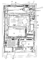
以下、本発明の実施の形態を、図面を参照して説明する。まず、遊技機の一例であるパチンコ遊技機1の全体の構成について説明する。図1はパチンコ遊技機1を正面からみた正面図である。
Hereinafter, embodiments of the present invention will be described with reference to the drawings. First, the overall configuration of a
パチンコ遊技機1は、縦長の方形状に形成された外枠(図示せず)と、外枠の内側に開閉可能に取り付けられた遊技枠とで構成される。また、パチンコ遊技機1は、遊技枠に開閉可能に設けられている額縁状に形成されたガラス扉枠2を有する。遊技枠は、外枠に対して開閉自在に設置される前面枠(図示せず)と、機構部品等が取り付けられる機構板(図示せず)と、それらに取り付けられる種々の部品(後述する遊技盤6を除く)とを含む構造体である。
The
ガラス扉枠2の下部表面には打球供給皿(上皿)3がある。打球供給皿3の下部には、打球供給皿3に収容しきれない遊技球を貯留する余剰球受皿4や、打球を発射する打球操作ハンドル(操作ノブ)5が設けられている。また、ガラス扉枠2の背面には、遊技盤6が着脱可能に取り付けられている。なお、遊技盤6は、それを構成する板状体と、その板状体に取り付けられた種々の部品とを含む構造体である。また、遊技盤6の前面には、打ち込まれた遊技球が流下可能な遊技領域7が形成されている。
On the lower surface of the
余剰球受皿(下皿)4を形成する部材には、例えば下皿本体の上面における手前側の所定位置(例えば下皿の中央部分)などに、スティック形状(棒形状)に構成され、遊技者が把持して複数方向(前後左右)に傾倒操作が可能なスティックコントローラ122が取り付けられている。なお、スティックコントローラ122には、遊技者がスティックコントローラ122の操作桿を操作手(例えば左手など)で把持した状態において、所定の操作指(例えば人差し指など)で押引操作することなどにより所定の指示操作が可能なトリガボタン121(図6を参照)が設けられ、スティックコントローラ122の操作桿の内部には、トリガボタン121に対する押引操作などによる所定の指示操作を検知するトリガセンサ125(図6を参照)が内蔵されている。また、スティックコントローラ122の下部における下皿の本体内部などには、操作桿に対する傾倒操作を検知する傾倒方向センサユニット123(図6を参照)が設けられている。また、スティックコントローラ122には、スティックコントローラ122を振動動作させるためのバイブレータ用モータ126(図6を参照)が内蔵されている。
The member that forms the extra ball tray (lower tray) 4 is configured in a stick shape (bar shape), for example, at a predetermined position on the front side of the upper surface of the lower tray main body (for example, the central portion of the lower tray). Is attached to the
打球供給皿(上皿)3を形成する部材には、例えば上皿本体の上面における手前側の所定位置(例えばスティックコントローラ122の上方)などに、遊技者が押下操作などにより所定の指示操作を可能なプッシュボタン120が設けられている。プッシュボタン120は、遊技者からの押下操作などによる所定の指示操作を、機械的、電気的、あるいは、電磁的に、検出できるように構成されていればよい。プッシュボタン120の設置位置における上皿の本体内部などには、プッシュボタン120に対してなされた遊技者の操作行為を検知するプッシュセンサ124(図6を参照)が設けられていればよい。図1に示す構成例では、プッシュボタン120とスティックコントローラ122の取付位置が、上皿及び下皿の中央部分において上下の位置関係にある。これに対して、上下の位置関係を保ったまま、プッシュボタン120及びスティックコントローラ122の取付位置を、上皿及び下皿において左右のいずれかに寄せた位置としてもよい。あるいは、プッシュボタン120とスティックコントローラ122の取付位置が上下の位置関係にはなく、例えば左右の位置関係にあるものとしてもよい。
The member that forms the hitting ball supply tray (upper plate) 3 is subjected to a predetermined instruction operation, for example, by a player pressing a predetermined position on the upper surface of the upper plate body (for example, above the stick controller 122). A
遊技領域7の中央付近には、液晶表示装置(LCD)で構成された演出表示装置9が設けられている。演出表示装置9の表示画面には、第1特別図柄または第2特別図柄の可変表示に同期した演出図柄の可変表示を行う演出図柄表示領域がある。よって、演出表示装置9は、演出図柄の可変表示を行う可変表示装置に相当する。演出図柄表示領域には、例えば「左」、「中」、「右」の3つの装飾用(演出用)の演出図柄を可変表示する図柄表示エリアがある。図柄表示エリアには「左」、「中」、「右」の各図柄表示エリアがあるが、図柄表示エリアの位置は、演出表示装置9の表示画面において固定的でなくてもよいし、図柄表示エリアの3つ領域が離れてもよい。演出表示装置9は、演出制御基板に搭載されている演出制御用マイクロコンピュータによって制御される。演出制御用マイクロコンピュータが、第1特別図柄表示器8aで第1特別図柄の可変表示が実行されているときに、その可変表示に伴って演出表示装置9で演出表示を実行させ、第2特別図柄表示器8bで第2特別図柄の可変表示が実行されているときに、その可変表示に伴って演出表示装置9で演出表示を実行させるので、遊技の進行状況を把握しやすくすることができる。
An
また、演出表示装置9において、最終停止図柄(例えば左右中図柄のうち中図柄)となる図柄以外の図柄が、所定時間継続して、大当り図柄(例えば左中右の図柄が同じ図柄で揃った図柄の組み合わせ)と一致している状態で停止、揺動、拡大縮小もしくは変形している状態、または、複数の図柄が同一図柄で同期して変動したり、表示図柄の位置が入れ替わっていたりして、最終結果が表示される前で大当り発生の可能性が継続している状態(以下、これらの状態をリーチ状態という。)において行われる演出をリーチ演出という。また、リーチ状態やその様子をリーチ態様という。さらに、リーチ演出を含む可変表示をリーチ可変表示という。そして、演出表示装置9に変動表示される図柄の表示結果が大当り図柄でない場合には「はずれ」となり、変動表示状態は終了する。遊技者は、大当りをいかにして発生させるかを楽しみつつ遊技を行う。
Further, in the
なお、この実施の形態では、演出表示装置9における液晶表示の演出として演出図柄の変動表示を行う場合を示しているが、演出表示装置9で行われる演出は、この実施の形態で示したものにかぎらず、例えば、所定のストーリー性をもつ演出を実行して、大当り判定や変動パターンの決定結果にもとづいてストーリーの結果を表示するような演出を実行するようにしてもよい。例えば、プロレスやサッカーの試合や敵味方のキャラクタが戦うバトル演出を行うとともに、大当りであれば試合やバトルに勝利する演出を行い、はずれであれば試合やバトルに敗北する演出を行うようにしてもよい。また、例えば、勝敗などの結果を表示するのではなく、物語などの所定のストーリーを順に展開させていくような演出を実行するようにしてもよい。
Note that, in this embodiment, a case is shown in which the effect symbol display is performed as a liquid crystal display effect in the
演出表示装置9の表示画面の右上方部には、演出図柄と後述する特別図柄および普通図柄とに次ぐ第4図柄を表示する第4図柄表示領域9c,9dが設けられている。この実施の形態では、後述する第1特別図柄の変動表示に同期して第1特別図柄用の第4図柄の変動表示が行われる第1特別図柄用の第4図柄表示領域9cと、第2特別図柄の変動表示に同期して第2特別図柄用の第4図柄の変動表示が行われる第2特別図柄用の第4図柄表示領域9dとが設けられている。
In the upper right part of the display screen of the
この実施の形態では、特別図柄の変動表示に同期して演出図柄の変動表示が実行されるのであるが(ただし、正確には、演出図柄の変動表示は、演出制御用マイクロコンピュータ100側で変動パターンコマンドにもとづいて認識した変動時間を計測することによって行われる。)、演出表示装置9を用いた演出を行う場合、例えば、演出図柄の変動表示を含む演出内容が画面上から一瞬消えるような演出が行われたり、可動物が画面上の全部または一部を遮蔽するような演出が行われるなど、演出態様が多様化してきている。そのため、演出表示装置9上の表示画面を見ていても、現在変動表示中の状態であるのか否か認識しにくい場合も生じている。そこで、この実施の形態では、演出表示装置9の表示画面の一部でさらに第4図柄の変動表示を行うことによって、第4図柄の状態を確認することにより現在変動表示中の状態であるのか否かを確実に認識可能としている。なお、第4図柄は、常に一定の動作で変動表示され、画面上から消えたり遮蔽物で遮蔽することはないため、常に視認することができる。
In this embodiment, the variation display of the effect symbol is executed in synchronization with the variation display of the special symbol (however, to be precise, the variation display of the effect symbol is varied on the
なお、第1特別図柄用の第4図柄と第2特別図柄用の第4図柄とを、第4図柄と総称することがあり、第1特別図柄用の第4図柄表示領域9cと第2特別図柄用の第4図柄表示領域9dを、第4図柄表示領域と総称することがある。
The 4th symbol for the first special symbol and the 4th symbol for the 2nd special symbol may be collectively referred to as the 4th symbol, and the 4th
第4図柄の変動(可変表示)は、第4図柄表示領域9c,9dを所定の表示色(例えば、青色)で一定の時間間隔で点灯と消灯とを繰り返す状態を継続することによって実現される。第1特別図柄表示器8aにおける第1特別図柄の可変表示と、第1特別図柄用の第4図柄表示領域9cにおける第1特別図柄用の第4図柄の可変表示とは同期している。第2特別図柄表示器8bにおける第2特別図柄の可変表示と、第2特別図柄用の第4図柄表示領域9dにおける第2特別図柄用の第4図柄の可変表示とは同期している。同期とは、可変表示の開始時点および終了時点が同じであって、可変表示の期間が同じであることをいう。
The variation (variable display) of the fourth symbol is realized by continuing the state where the fourth
また、第1特別図柄表示器8aにおいて大当り図柄が停止表示されるときには、第1特別図柄用の第4図柄表示領域9cにおいて大当りを想起させる表示色(はずれとは異なる表示色。例えば、はずれのときには青色で表示されるのに対して、大当りのときには赤色で表示される。なお、大当りの種類(確変大当りや通常大当りのいずれであるか)に応じて表示色を異ならせてもよい。また、大入賞口への遊技球の入賞を期待できる大当り(例えば、突然確変大当り以外の大当り)であるか否かに応じて表示色を異ならせてもよく、ラウンド数の異なる複数種類の大当りに制御可能である場合には、大当り遊技において継続されるラウンド数に応じて表示色を異ならせてもよい。また、この実施の形態のように、各大当りのラウンド数が同じであっても、例えば、1ラウンドあたりの大入賞口の開放時間が短く(例えば0.1秒)、実質的に大入賞口への遊技球の入賞を期待できない大当りと、1ラウンドあたりの大入賞口の開放時間が長く(例えば29秒)、実質的に大入賞口への遊技球の入賞を期待できる大当りとがある場合には、実質的に大入賞口への遊技球の入賞を期待できるか否かに応じて表示色を異ならせてもよい。また、例えば、1ラウンドあたりの大入賞口の開放回数が異なることによって、実質的に大入賞口への遊技球の入賞を期待できる大当りと期待できない大当りがある場合にも、実質的に大入賞口への遊技球の入賞を期待できるか否かに応じて表示色を異ならせてもよい。
When the big hit symbol is stopped and displayed on the first
また、第2特別図柄表示器8bにおいて大当り図柄が停止表示されるときには、第2特別図柄用の第4図柄表示領域9dにおいて大当りを想起させる表示色(はずれとは異なる表示色。例えば、はずれのときには青色で表示されるのに対して、大当りのときには赤色で表示される。なお、大当りの種類(確変大当りや通常大当りのいずれであるか)に応じて表示色を異ならせてもよい。また、大入賞口への遊技球の入賞を期待できる大当り(例えば、突然確変大当り以外の大当り)であるか否かに応じて表示色を異ならせてもよく、ラウンド数の異なる複数種類の大当りに制御可能である場合には、大当り遊技において継続されるラウンド数に応じて表示色を異ならせてもよい。また、この実施の形態のように、各大当りのラウンド数が同じであっても、例えば、1ラウンドあたりの大入賞口の開放時間が短く(例えば0.1秒)、実質的に大入賞口への遊技球の入賞を期待できない大当りと、1ラウンドあたりの大入賞口の開放時間が長く(例えば29秒)、実質的に大入賞口への遊技球の入賞を期待できる大当りとがある場合には、実質的に大入賞口への遊技球の入賞を期待できるか否かに応じて表示色を異ならせてもよい。また、例えば、1ラウンドあたりの大入賞口の開放回数が異なることによって、実質的に大入賞口への遊技球の入賞を期待できる大当りと期待できない大当りがある場合にも、実質的に大入賞口への遊技球の入賞を期待できるか否かに応じて表示色を異ならせてもよい。
Further, when the big hit symbol is stopped and displayed on the second special symbol display 8b, the display color reminiscent of the big hit in the fourth
なお、第4図柄表示領域9c,9dの消灯時の表示色は、消灯したときに背景画像と同化して見えなくなることを防止するために、背景画像とは異なる表示色(例えば、黒色)であることが望ましい。
The display colors when the fourth
なお、この実施の形態では、第4図柄表示領域を演出表示装置9の表示画面の一部に設ける場合を示しているが、演出表示装置9とは別に、ランプやLEDなどの発光体を用いて第4図柄表示領域を実現するようにしてもよい。この場合、例えば、第4図柄の変動(可変表示)を、2つのLEDが交互に点灯する状態を継続することによって実現されるようにしてもよく、2つのLEDのうちのいずれのLEDが停止表示されたかによって大当り図柄が停止表示されたか否かを表すようにしてもよい。
In this embodiment, the case where the 4th symbol display area is provided on a part of the display screen of the
また、この実施の形態では、第1特別図柄と第2特別図柄とにそれぞれ対応させて別々の第4図柄表示領域9c,9dを備える場合を示しているが、第1特別図柄と第2特別図柄とに対して共通の第4図柄表示領域を演出表示装置9の表示画面の一部に設けるようにしてもよい。また、第1特別図柄と第2特別図柄とに対して共通の第4図柄表示領域をランプやLEDなどの発光体を用いて実現するようにしてもよい。この場合、第1特別図柄の変動表示に同期して第4図柄の変動表示を実行するときと、第2特別図柄の変動表示に同期して第4図柄の変動表示を実行するときとで、例えば、一定の時間間隔で異なる表示色の表示を点灯および消灯を繰り返すような表示を行うことによって、第4図柄の変動表示を区別して実行するようにしてもよい。また、第1特別図柄の変動表示に同期して第4図柄の変動表示を実行するときと、第2特別図柄の変動表示に同期して第4図柄の変動表示を実行するときとで、例えば、異なる時間間隔で点灯および消灯を繰り返すような表示を行うことによって、第4図柄の変動表示を区別して実行するようにしてもよい。また、例えば、第1特別図柄の変動表示に対応して停止図柄を導出表示するときと、第2特別図柄の変動表示に対応して停止図柄を導出表示するときとで、同じ大当り図柄であっても異なる態様の停止図柄を停止表示するようにしてもよい。
Further, in this embodiment, a case is shown in which separate fourth
演出表示装置9の右方には、識別情報としての第1特別図柄を可変表示する第1特別図柄表示器(第1可変表示部)8aが設けられている。この実施の形態では、第1特別図柄表示器8aは、0〜9の数字を可変表示可能な簡易で小型の表示器(例えば7セグメントLED)で実現されている。すなわち、第1特別図柄表示器8aは、0〜9の数字(または、記号)を可変表示するように構成されている。また、演出表示装置9の右方(第1特別図柄表示器8aの右隣)には、識別情報としての第2特別図柄を可変表示する第2特別図柄表示器(第2可変表示部)8bも設けられている。第2特別図柄表示器8bは、0〜9の数字を可変表示可能な簡易で小型の表示器(例えば7セグメントLED)で実現されている。すなわち、第2特別図柄表示器8bは、0〜9の数字(または、記号)を可変表示するように構成されている。
On the right side of the
小型の表示器は、例えば方形状に形成されている。また、この実施の形態では、第1特別図柄の種類と第2特別図柄の種類とは同じ(例えば、ともに0〜9の数字)であるが、種類が異なっていてもよい。また、第1特別図柄表示器8aおよび第2特別図柄表示器8bは、それぞれ、例えば、00〜99の数字(または、2桁の記号)を可変表示するように構成されていてもよい。
The small display is formed in a square shape, for example. In this embodiment, the type of the first special symbol and the type of the second special symbol are the same (for example, both 0 to 9), but the types may be different. Further, the first
以下、第1特別図柄と第2特別図柄とを特別図柄と総称することがあり、第1特別図柄表示器8aと第2特別図柄表示器8bとを特別図柄表示器(可変表示部)と総称することがある。
Hereinafter, the first special symbol and the second special symbol may be collectively referred to as a special symbol, and the first
なお、この実施の形態では、2つの特別図柄表示器8a,8bを備える場合を示しているが、遊技機は、特別図柄表示器を1つのみ備えるものであってもよい。
Although this embodiment shows a case where two
第1特別図柄または第2特別図柄の可変表示は、可変表示の実行条件である第1始動条件または第2始動条件が成立(例えば、遊技球が第1始動入賞口13または第2始動入賞口14を通過(入賞を含む)したこと)した後、可変表示の開始条件(例えば、保留記憶数が0でない場合であって、第1特別図柄および第2特別図柄の可変表示が実行されていない状態であり、かつ、大当り遊技が実行されていない状態)が成立したことにもとづいて開始され、可変表示時間(変動時間)が経過すると表示結果(停止図柄)を導出表示する。なお、遊技球が通過するとは、入賞口やゲートなどのあらかじめ入賞領域として定められている領域を遊技球が通過したことであり、入賞口に遊技球が入った(入賞した)ことを含む概念である。また、表示結果を導出表示するとは、図柄(識別情報の例)を最終的に停止表示させることである。
For the variable display of the first special symbol or the second special symbol, the first start condition or the second start condition, which is the variable display execution condition, is satisfied (for example, the game ball has the first
演出表示装置9の下方には、第1始動入賞口13を有する入賞装置が設けられている。第1始動入賞口13に入賞した遊技球は、遊技盤6の背面に導かれ、第1始動口スイッチ13aによって検出される。
A winning device having a first
また、第1始動入賞口(第1始動口)13を有する入賞装置の下方には、遊技球が入賞可能な第2始動入賞口14を有する可変入賞球装置15が設けられている。第2始動入賞口(第2始動口)14に入賞した遊技球は、遊技盤6の背面に導かれ、第2始動口スイッチ14aによって検出される。可変入賞球装置15は、ソレノイド16によって開状態とされる。可変入賞球装置15が開状態になることによって、遊技球が第2始動入賞口14に入賞可能になり(始動入賞し易くなり)、遊技者にとって有利な状態になる。可変入賞球装置15が開状態になっている状態では、第1始動入賞口13よりも、第2始動入賞口14に遊技球が入賞しやすい。また、可変入賞球装置15が閉状態になっている状態では、遊技球は第2始動入賞口14に入賞しない。従って、可変入賞球装置15が閉状態になっている状態では、第2始動入賞口14よりも、第1始動入賞口13に遊技球が入賞しやすい。なお、可変入賞球装置15が閉状態になっている状態において、入賞はしづらいものの、入賞することは可能である(すなわち、遊技球が入賞しにくい)ように構成されていてもよい。
A variable winning
以下、第1始動入賞口13と第2始動入賞口14とを総称して始動入賞口または始動口ということがある。
Hereinafter, the first
可変入賞球装置15が開放状態に制御されているときには可変入賞球装置15に向かう遊技球は第2始動入賞口14に極めて入賞しやすい。そして、第1始動入賞口13は演出表示装置9の直下に設けられているが、演出表示装置9の下端と第1始動入賞口13との間の間隔をさらに狭めたり、第1始動入賞口13の周辺で釘を密に配置したり、第1始動入賞口13の周辺での釘配列を遊技球を第1始動入賞口13に導きづらくして、第2始動入賞口14の入賞率の方を第1始動入賞口13の入賞率よりもより高くするようにしてもよい。
When the variable winning
なお、この実施の形態では、図1に示すように、第2始動入賞口14に対してのみ開閉動作を行う可変入賞球装置15が設けられているが、第1始動入賞口13および第2始動入賞口14のいずれについても開閉動作を行う可変入賞球装置が設けられている構成であってもよい。
In this embodiment, as shown in FIG. 1, the variable winning
第2特別図柄表示器8bの上方には、第2始動入賞口14に入った有効入賞球数すなわち第2保留記憶数を表示する4つの表示器からなる第2特別図柄保留記憶表示器18bが設けられている。第2特別図柄保留記憶表示器18bは、有効始動入賞がある毎に、点灯する表示器の数を1増やす。そして、第2特別図柄表示器8bでの可変表示が開始される毎に、点灯する表示器の数を1減らす。
Above the second special symbol display 8b, there is a second special symbol
また、第2特別図柄保留記憶表示器18bのさらに上方には、第1始動入賞口13に入った有効入賞球数すなわち第1保留記憶数(保留記憶を、始動記憶または始動入賞記憶ともいう。)を表示する4つの表示器からなる第1特別図柄保留記憶表示器18aが設けられている。第1特別図柄保留記憶表示器18aは、有効始動入賞がある毎に、点灯する表示器の数を1増やす。そして、第1特別図柄表示器8aでの可変表示が開始される毎に、点灯する表示器の数を1減らす。
Further, above the second special symbol
また、演出表示装置9の表示画面の下部には、第1保留記憶数を表示する第1保留記憶表示部18cと、第2保留記憶数を表示する第2保留記憶表示部18dとが設けられている。なお、第1保留記憶数と第2保留記憶数との合計である合計数(合算保留記憶数)を表示する領域(合算保留記憶表示部)が設けられるようにしてもよい。そのように、合計数を表示する合算保留記憶表示部が設けられているようにすれば、可変表示の開始条件が成立していない実行条件の成立数の合計を把握しやすくすることができる。
Also, at the lower part of the display screen of the
演出表示装置9は、第1特別図柄表示器8aによる第1特別図柄の可変表示時間中、および第2特別図柄表示器8bによる第2特別図柄の可変表示時間中に、装飾用(演出用)の図柄としての演出図柄の可変表示を行う。第1特別図柄表示器8aにおける第1特別図柄の可変表示と、演出表示装置9における演出図柄の可変表示とは同期している。また、第2特別図柄表示器8bにおける第2特別図柄の可変表示と、演出表示装置9における演出図柄の可変表示とは同期している。また、第1特別図柄表示器8aにおいて大当り図柄が停止表示されるときと、第2特別図柄表示器8bにおいて大当り図柄が停止表示されるときには、演出表示装置9において大当りを想起させるような演出図柄の組み合わせが停止表示される。
The
また、図1に示すように、可変入賞球装置15の下方には、特別可変入賞球装置20が設けられている。特別可変入賞球装置20は開閉板を備え、第1特別図柄表示器8aに特定表示結果(大当り図柄)が導出表示されたときと、第2特別図柄表示器8bに特定表示結果(大当り図柄)が導出表示されたときに生起する特定遊技状態(大当り遊技状態)においてソレノイド21によって開閉板が開放状態に制御されることによって、入賞領域となる大入賞口が開放状態になる。大入賞口に入賞した遊技球はカウントスイッチ23で検出される。
Further, as shown in FIG. 1, a special variable winning
演出表示装置9の左方には、普通図柄を可変表示する普通図柄表示器10が設けられている。この実施の形態では、普通図柄表示器10は、0〜9の数字を可変表示可能な簡易で小型の表示器(例えば7セグメントLED)で実現されている。すなわち、普通図柄表示器10は、0〜9の数字(または、記号)を可変表示するように構成されている。また、小型の表示器は、例えば方形状に形成されている。なお、普通図柄表示器10は、例えば、00〜99の数字(または、2桁の記号)を可変表示するように構成されていてもよい。また、普通図柄表示器10は、7セグメントLEDなどにかぎらず、例えば、所定の記号表示を点灯表示可能な表示器(例えば、「○」や「×」を交互に点灯表示可能な装飾ランプ)で構成されていてもよい。
On the left side of the
遊技球がゲート32を通過しゲートスイッチ32aで検出されると、普通図柄表示器10の表示の可変表示が開始される。そして、普通図柄表示器10における停止図柄が所定の図柄(当り図柄。例えば、図柄「7」。)である場合に、可変入賞球装置15が所定回数、所定時間だけ開状態になる。すなわち、可変入賞球装置15の状態は、普通図柄の停止図柄が当り図柄である場合に、遊技者にとって不利な状態から有利な状態(第2始動入賞口14に遊技球が入賞可能な状態)に変化する。普通図柄表示器10の近傍には、ゲート32を通過した入賞球数を表示する4つのLEDによる表示部を有する普通図柄保留記憶表示器41が設けられている。ゲート32への遊技球の通過がある毎に、すなわちゲートスイッチ32aによって遊技球が検出される毎に、普通図柄保留記憶表示器41は点灯するLEDを1増やす。そして、普通図柄表示器10の可変表示が開始される毎に、点灯するLEDを1減らす。さらに、通常状態に比べて大当りとすることに決定される確率が高い状態である確変状態(通常状態と比較して、特別図柄の変動表示結果として大当りと判定される確率が高められた状態)では、普通図柄表示器10における停止図柄が当り図柄になる確率が高められるとともに、可変入賞球装置15の開放時間と開放回数が高められる。また、確変状態ではないが図柄の変動時間が短縮されている時短状態(特別図柄の可変表示時間が短縮される遊技状態。なお、この実施の形態では、後述するように、第1時短状態と第2時短状態とがある。)でも、可変入賞球装置15の開放時間と開放回数が高められる。
When the game ball passes through the
遊技盤6の下部には、入賞しなかった打球が取り込まれるアウト口26がある。また、遊技領域7の外側の左右上部および左右下部には、所定の音声出力として効果音や音声を発声する4つのスピーカ27が設けられている。遊技領域7の外周には、前面枠に設けられた枠LED28が設けられている。
At the lower part of the
遊技機には、遊技者が打球操作ハンドル5を操作することに応じて駆動モータを駆動し、駆動モータの回転力を利用して遊技球を遊技領域7に発射する打球発射装置(図示せず)が設けられている。打球発射装置から発射された遊技球は、遊技領域7を囲むように円形状に形成された打球レールを通って遊技領域7に入り、その後、遊技領域7を下りてくる。遊技球が第1始動入賞口13に入り第1始動口スイッチ13aで検出されると、第1特別図柄の可変表示を開始できる状態であれば(例えば、特別図柄の可変表示が終了し、第1の開始条件が成立したこと)、第1特別図柄表示器8aにおいて第1特別図柄の可変表示(変動)が開始されるとともに、演出表示装置9において演出図柄の可変表示が開始される。すなわち、第1特別図柄および演出図柄の可変表示は、第1始動入賞口13への入賞に対応する。第1特別図柄の可変表示を開始できる状態でなければ、第1保留記憶数が上限値に達していないことを条件として、第1保留記憶数を1増やす。
In the gaming machine, a ball striking device (not shown) that drives a driving motor in response to a player operating the batting operation handle 5 and uses the rotational force of the driving motor to launch a gaming ball to the gaming area 7. ) Is provided. A game ball launched from the ball striking device enters the
遊技球が第2始動入賞口14に入り第2始動口スイッチ14aで検出されると、第2特別図柄の可変表示を開始できる状態であれば(例えば、特別図柄の可変表示が終了し、第2の開始条件が成立したこと)、第2特別図柄表示器8bにおいて第2特別図柄の可変表示(変動)が開始されるとともに、演出表示装置9において演出図柄の可変表示が開始される。すなわち、第2特別図柄および演出図柄の可変表示は、第2始動入賞口14への入賞に対応する。第2特別図柄の可変表示を開始できる状態でなければ、第2保留記憶数が上限値に達していないことを条件として、第2保留記憶数を1増やす。
When the game ball enters the second
この実施の形態では、確変大当りとなった場合には、遊技状態を高確率状態に移行するとともに、遊技球が始動入賞しやすくなる(すなわち、特別図柄表示器8a,8bや演出表示装置9における可変表示の実行条件が成立しやすくなる)ように制御された遊技状態である高ベース状態に移行する。また、遊技状態が時短状態に移行されたときも、高ベース状態に移行する。高ベース状態である場合には、例えば、高ベース状態でない場合と比較して、可変入賞球装置15が開状態となる頻度が高められたり、可変入賞球装置15が開状態となる時間が延長されたりして、始動入賞しやすくなる。
In this embodiment, when the probability variation is a big hit, the game state is shifted to a high probability state, and the game ball is easily started and won (that is, in the
なお、可変入賞球装置15が開状態となる時間を延長する(開放延長状態ともいう)のでなく、普通図柄表示器10における停止図柄が当り図柄になる確率が高められる普通図柄確変状態に移行することによって、高ベース状態に移行してもよい。普通図柄表示器10における停止図柄が所定の図柄(当り図柄)となると、可変入賞球装置15が所定回数、所定時間だけ開状態になる。この場合、普通図柄確変状態に移行制御することによって、普通図柄表示器10における停止図柄が当り図柄になる確率が高められ、可変入賞球装置15が開状態となる頻度が高まる。従って、普通図柄確変状態に移行すれば、可変入賞球装置15の開放時間と開放回数が高められ、始動入賞しやすい状態(高ベース状態)となる。すなわち、可変入賞球装置15の開放時間と開放回数は、普通図柄の停止図柄が当り図柄であったり、特別図柄の停止図柄が確変図柄である場合等に高められ、遊技者にとって不利な状態から有利な状態(始動入賞しやすい状態)に変化する。なお、開放回数が高められることは、閉状態から開状態になることも含む概念である。
Instead of extending the time during which the variable winning
また、普通図柄表示器10における普通図柄の変動時間(可変表示期間)が短縮される普通図柄時短状態に移行することによって、高ベース状態に移行してもよい。普通図柄時短状態では、普通図柄の変動時間が短縮されるので、普通図柄の変動が開始される頻度が高くなり、結果として普通図柄が当りとなる頻度が高くなる。従って、普通図柄が当たりとなる頻度が高くなることによって、可変入賞球装置15が開状態となる頻度が高くなり、始動入賞しやすい状態(高ベース状態)となる。
Moreover, you may transfer to a high base state by shifting to the normal symbol time short state where the fluctuation time (variable display period) of the normal symbol in the
また、特別図柄や演出図柄の変動時間(可変表示期間)が短縮される時短状態に移行することによって、特別図柄や演出図柄の変動時間が短縮されるので、特別図柄や演出図柄の変動が開始される頻度が高くなり(換言すれば、保留記憶の消化が速くなる。)、無効な始動入賞が生じてしまう事態を低減することができる。従って、有効な始動入賞が発生しやすくなり、結果として、大当り遊技が行われる可能性が高まる。なお、この実施の形態では、時短状態には、後述するように、第1時短状態と、第1時短状態よりもさらに変動時間が短い第2時短状態との2種類がある。なお、第1時短状態および第2時短状態については後で説明する。 In addition, the change time of special symbols and production symbols will be shortened by shifting to the short time state when the variation time (variable display period) of special symbols and production symbols is shortened. The frequency of being played (in other words, the digestion of the reserved memory becomes faster), and the situation where an invalid start prize is generated can be reduced. Therefore, an effective start winning is likely to occur, and as a result, the possibility of a big hit game being increased. In this embodiment, as described later, there are two types of time-short states: a first time-short state and a second time-short state in which the variation time is shorter than that of the first time-short state. The first short time state and the second short time state will be described later.
さらに、上記に示した全ての状態(開放延長状態、普通図柄確変状態、普通図柄時短状態および特別図柄時短状態)に移行させることによって、始動入賞しやすくなる(高ベース状態に移行する)ようにしてもよい。また、上記に示した各状態(開放延長状態、普通図柄確変状態、普通図柄時短状態および特別図柄時短状態)のうちのいずれか複数の状態に移行させることによって、始動入賞しやすくなる(高ベース状態に移行する)ようにしてもよい。また、上記に示した各状態(開放延長状態、普通図柄確変状態、普通図柄時短状態および特別図柄時短状態)のうちのいずれか1つの状態にのみ移行させることによって、始動入賞しやすくなる(高ベース状態に移行する)ようにしてもよい。 Furthermore, by making transitions to all the states shown above (open extended state, normal symbol probability change state, normal symbol short time state, and special symbol short time state), it will be easier to win a start (shift to a high base state). May be. In addition, it is easier to win a start (high base) by shifting to any one of the above states (open extended state, normal symbol probability changing state, normal symbol short time state, and special symbol short time state). Transition to a state). In addition, it is easier to win a start by shifting to any one of the above states (open extended state, normal symbol probability changing state, normal symbol short time state, and special symbol short time state). You may make it move to a base state.
次に、パチンコ遊技機1の裏面の構造について図2を参照して説明する。図2は、遊技機を裏面から見た背面図である。図2に示すように、パチンコ遊技機1裏面側では、演出表示装置9を制御する演出制御用マイクロコンピュータ100が搭載された演出制御基板80を含む変動表示制御ユニット、遊技制御用マイクロコンピュータ等が搭載された遊技制御基板(主基板)31、音声出力基板70、ランプドライバ基板35、および球払出制御を行なう払出制御用マイクロコンピュータ等が搭載された払出制御基板37等の各種基板が設置されている。なお、遊技制御基板31は基板収納ケース200に収納されている。
Next, the structure of the back surface of the
さらに、パチンコ遊技機1裏面側には、DC30V、DC21V、DC12VおよびDC5V等の各種電源電圧を作成する電源回路が搭載された電源基板910やタッチセンサ基板91が設けられている。電源基板910には、パチンコ遊技機1における遊技制御基板31および各電気部品制御基板(演出制御基板80および払出制御基板37)やパチンコ遊技機1に設けられている各電気部品(電力が供給されることによって動作する部品)への電力供給を実行あるいは遮断するための電力供給許可手段としての電源スイッチ、遊技制御基板31の遊技制御用マイクロコンピュータ560のRAM55をクリアするためのクリアスイッチが設けられている。さらに、電源スイッチの内側(基板内部側)には、交換可能なヒューズが設けられている。なお、この実施の形態では、クリアスイッチが電源基板910に設けられている場合を説明しているが、クリアスイッチの設置場所は、この実施の形態で示したものにかぎられない。例えば、遊技制御基板31や払出制御基板37など、電源基板910以外の基板に設けられていてもよい。
Further, on the back side of the
なお、各制御基板には、制御用マイクロコンピュータを含む制御手段が搭載されている。制御手段は、遊技制御手段等からのコマンドとしての指令信号(制御信号)に従って遊技機に設けられている電気部品(遊技用装置:球払出装置97、演出表示装置9、ランプやLEDなどの発光体、スピーカ27等)を制御する。以下、主基板31を制御基板に含めて説明を行うことがある。その場合には、制御基板に搭載される制御手段は、遊技制御手段と、遊技制御手段等からの指令信号に従って遊技機に設けられている電気部品を制御する手段とのそれぞれを指す。また、主基板31以外のマイクロコンピュータが搭載された基板をサブ基板ということがある。なお、球払出装置97は、遊技球を誘導する通路とステッピングモータ等により駆動されるスプロケット等によって誘導された遊技球を上皿や下皿に払い出すための装置であって、払い出された賞球や貸し球をカウントする払出個数カウントスイッチ等もユニットの一部として構成されている。
Each control board is equipped with control means including a control microcomputer. The control means is an electrical component (game device:
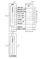
パチンコ遊技機1裏面において、上方には、各種情報をパチンコ遊技機1の外部に出力するための各端子を備えたターミナル基板160が設置されている。ターミナル基板160には、例えば、大当り遊技状態の発生を示す大当り情報等の情報出力信号(図41に示す始動口信号、図柄確定回数1信号、図柄確定回数2信号、大当り1信号、大当り2信号、大当り3信号、時短信号、セキュリティ信号、高確中信号、賞球信号1、遊技機エラー状態信号)を外部出力するための情報出力端子が設けられている。
On the back side of the
なお、この実施の形態では、遊技枠側の裏面上方にターミナル基板160を設ける場合を示しているが、ターミナル基板160の配置の仕方は、この実施の形態で示したものにかぎられない。例えば、演出制御基板80を含む変動表示制御ユニットの背面側に裏カバーを設けて、その裏カバーの上にターミナル基板160を取り付けることによって、遊技盤側にターミナル基板160を配置するようにしてもよい。
In this embodiment, the
貯留タンク38に貯留された遊技球は誘導レール(図示せず)を通り、カーブ樋を経て払出ケース40Aで覆われた球払出装置97に至る。球払出装置97の上方には、遊技媒体切れ検出手段としての球切れスイッチ187が設けられている。球切れスイッチ187が球切れを検出すると、球払出装置97の払出動作が停止する。球切れスイッチ187は遊技球通路内の遊技球の有無を検出するスイッチであるが、貯留タンク38内の補給球の不足を検出する球切れ検出スイッチ167も誘導レールにおける上流部分(貯留タンク38に近接する部分)に設けられている。球切れ検出スイッチ167が遊技球の不足を検知すると、遊技機設置島に設けられている補給機構からパチンコ遊技機1に対して遊技球の補給が行なわれる。
The game ball stored in the
入賞にもとづく景品としての遊技球や球貸し要求にもとづく遊技球が多数払出されて打球供給皿3が満杯になると、遊技球は、余剰球誘導通路を経て余剰球受皿4に導かれる。さらに遊技球が払出されると、感知レバー(図示せず)が貯留状態検出手段としての満タンスイッチを押圧して、貯留状態検出手段としての満タンスイッチがオンする。その状態では、球払出装置内の払出モータの回転が停止して球払出装置の動作が停止するとともに打球発射装置の駆動も停止する。
When a large number of game balls as prizes based on winning a prize or a game ball based on a ball lending request are paid out and the hitting
図3は、第2始動入賞口14内の断面構造の具体例を示す説明図である。図3に示すように、第2始動入賞口14内には、始動入賞口内に入賞した遊技球を検出可能な2つのスイッチ(第2始動口スイッチ14aと入賞確認スイッチ14b)が設けられている。この実施の形態では、図3に示すように、第2始動入賞口14内で、第2始動口スイッチ14aと入賞確認スイッチ14bとが上下に配置されている(本例では、第2始動口スイッチ14aが上側に配置され、入賞確認スイッチ14bが下側に配置されている)。従って、この実施の形態では、第2始動入賞口14内に入賞した遊技球は、遊技盤6の背面に導かれ、まず第2始動口スイッチ14aで検出され、次いで入賞確認スイッチ14bで検出される。
FIG. 3 is an explanatory diagram illustrating a specific example of a cross-sectional structure in the second
また、第2始動口スイッチ14aと入賞確認スイッチ14bとして、それぞれ異なる検出方式のスイッチが用いられる。この実施の形態では、第2始動口スイッチ14aとして近接スイッチを用い、入賞確認スイッチ14bとしてフォトセンサを用いる場合を示している。 Further, as the second start port switch 14a and the winning confirmation switch 14b, switches of different detection methods are used. In this embodiment, a case where a proximity switch is used as the second start port switch 14a and a photosensor is used as the winning confirmation switch 14b is shown.
また、この実施の形態では、後述するように、第2始動口スイッチ14aによって遊技球が検出されたことにもとづいて、特別図柄の変動表示が開始され、賞球払出が実行される。また、後述するように、第2始動口スイッチ14aによる検出結果に加えて入賞確認スイッチ14bの検出結果にもとづいて異常入賞の発生の有無が判定され、異常入賞の発生を検出したことにもとづいてセキュリティ信号が外部出力される。従って、この実施の形態では、入賞確認スイッチ14bは、異常入賞の判定のみに用いられる。 In this embodiment, as will be described later, on the basis of the fact that a game ball is detected by the second start port switch 14a, a special symbol variation display is started and a prize ball payout is executed. Further, as will be described later, the presence or absence of occurrence of an abnormal winning is determined based on the detection result of the winning confirmation switch 14b in addition to the detection result of the second start opening switch 14a, and the occurrence of the abnormal winning is detected. A security signal is output externally. Therefore, in this embodiment, the winning confirmation switch 14b is used only for determining an abnormal winning.
なお、第2始動口スイッチ14aおよび入賞確認スイッチ14bの検出方式は、この実施の形態で示したものにかぎらず、例えば、第2始動口スイッチ14aと入賞確認スイッチ14bとで異なる検出方式であれば、逆に第2始動口スイッチ14aとしてフォトセンサを用い、入賞確認スイッチ14bとして近接スイッチを用いてもよい。この場合、フォトセンサである第2始動口スイッチ14aの検出結果にもとづいて特別図柄の変動表示や賞球払出処理が実行され、近接スイッチである入賞確認スイッチ14bの検出結果は、第2始動入賞口14の異常入賞の判定のみに用いられることになる。また、例えば、電磁式のスイッチである近接スイッチや光学式のフォトセンサに代えて、第2始動口スイッチ14aまたは入賞確認スイッチ14bとして、機械式のスイッチ(マイクロスイッチなど)を用いてもよい。
The detection method of the second start port switch 14a and the winning confirmation switch 14b is not limited to that shown in this embodiment. For example, the detection method may be different between the second starting port switch 14a and the winning confirmation switch 14b. For example, a photo sensor may be used as the second start port switch 14a, and a proximity switch may be used as the winning confirmation switch 14b. In this case, the special symbol change display and the winning ball payout process are executed based on the detection result of the second start port switch 14a which is a photosensor, and the detection result of the winning confirmation switch 14b which is a proximity switch is the second start winning prize. It is used only for the determination of the abnormal winning of the
図4は、遊技球を検出可能な検出手段の方式を説明するための回路図である。図4(A)には、第2始動口スイッチ14a(近接スイッチ)が示されている。第2始動口スイッチ14aの一方の端子には、電源基板910から+12V電源電圧が供給されている。第2始動口スイッチ14aの他方の端子の電圧レベルである検出信号は、主基板31に入力される。主基板31において、検出信号は、入力ドライバ回路から遊技制御用マイクロコンピュータの入力ポートに入力される。また、第2始動口スイッチ14aの出力側には、一端が接地されている抵抗RとコンデンサCが接続されている。
FIG. 4 is a circuit diagram for explaining a method of detection means capable of detecting a game ball. FIG. 4A shows the second start port switch 14a (proximity switch). The + 12V power supply voltage is supplied from the
近接スイッチである第2始動口スイッチ14aに設けられている穴を金属の遊技球が通過するとコイルLに逆起電力が生じ、コイルLの等価的な抵抗値が極めて大きくなる。従って、第2始動口スイッチ14aの出力は、0Vに近いローレベルになる。すなわち、検出信号は、ローレベルである。第2始動口スイッチ14aに設けられている穴を金属の遊技球が通過していない場合には、第2始動口スイッチ14aの出力は、+12VがコイルLと抵抗Rの抵抗値で分圧された値であり、ハイレベルであるとみなされるしきい値レベルを越える。すなわち、検出信号は、ハイレベルである。従って、この実施の形態では、遊技制御用マイクロコンピュータは、第2始動口スイッチ14aからの出力がハイレベルであれば第2始動口スイッチ14aがオフ状態であると判断することができ、第2始動口スイッチ14aからの出力がローレベルであれば第2始動口スイッチ14aがオン状態であると判断することができる(すなわち、第2始動口スイッチ14aの出力は負論理となっている)。なお、検出信号のレベルを入力ドライバ回路で論理反転してから遊技制御用マイクロコンピュータ560に入力するように構成してもよい。
When a metal game ball passes through a hole provided in the second start port switch 14a that is a proximity switch, a counter electromotive force is generated in the coil L, and the equivalent resistance value of the coil L becomes extremely large. Therefore, the output of the second start port switch 14a becomes a low level close to 0V. That is, the detection signal is at a low level. When the metal game ball does not pass through the hole provided in the second start port switch 14a, the output of the second start port switch 14a is divided by + 12V by the resistance value of the coil L and the resistance R. Exceeding a threshold level that is considered high. That is, the detection signal is at a high level. Therefore, in this embodiment, the game control microcomputer can determine that the second start port switch 14a is in the OFF state if the output from the second start port switch 14a is at a high level. If the output from the start port switch 14a is at a low level, it can be determined that the second start port switch 14a is in an ON state (that is, the output of the second start port switch 14a has a negative logic). The detection signal level may be logically inverted by the input driver circuit and then input to the
図4(B)には、入賞確認スイッチ14b(フォトセンサ)が示されている。図4(B)に示すフォトセンサは、発光する発光ダイオード(LED)341と、受光して電流を出力するフォトトランジスタ342とで構成されている。発光ダイオード341およびフォトトランジスタ342の近傍を遊技球が通過すると、遊技球が反射した発光ダイオード341からの光をフォトトランジスタ342が受光して出力側に電流を流す。なお、この場合、フォトトランジスタ342のコレクタ端子からエミッタ端子の向きに電流が流れることにより、フォトセンサの検出信号は、近接スイッチと同様に負論理である。フォトセンサの出力側は主基板31に接続され、主基板31において、フォトセンサの検出信号は、入力ドライバ回路から遊技制御用マイクロコンピュータの入力ポートに入力される。フォトセンサの出力側(具体的には、フォトトランジスタ342の出力側)に電流が流れると、入力ドライバ回路は、ハイレベルの検出信号を遊技制御用マイクロコンピュータに出力する。なお、近接スイッチと同様に、検出信号のレベルを入力ドライバ回路で論理反転してから遊技制御用マイクロコンピュータ560に入力するように構成してもよい。
FIG. 4B shows a winning confirmation switch 14b (photo sensor). The photosensor illustrated in FIG. 4B includes a light-emitting diode (LED) 341 that emits light and a
遊技制御用マイクロコンピュータは、入力ドライバ回路からの検出信号がローレベルである場合に、遊技球がフォトセンサを通過したと判定することができる。 The game control microcomputer can determine that the game ball has passed through the photosensor when the detection signal from the input driver circuit is at a low level.
なお、この実施の形態では、フォトセンサとして反射型のフォトセンサが用いられるが、図4(C)における上段に示すように、発光素子(LED341)と受光素子(フォトトランジスタ342)とを入賞球経路を挟むように対向させて設置し、遊技球が発光素子からの光を遮ることによって受光素子が光を検出しなくなることによって、発光素子と受光素子との間を通過した遊技球を検出する透過型のフォトセンサを用いてもよい。透過型のフォトセンサを用いる場合に、図4(C)における下段に示すように、発光素子の光軸(図4(C)において黒丸で例示されている。)が、遊技球経路(入賞球経路)を通過する遊技球の中央部からずれるように、発光素子および受光素子を設置することが好ましい。光軸が遊技球の中央部に相当するように設置する場合に比べて、連続して通過する2つの遊技球の間隔が相対的に広い部分(図4(C)における「空隙」の部分)において遊技球を検知することができ、2つの遊技球を別個に検出しやすいからである。同様の理由で、図4(B)に例示する反射型のフォトセンサを用いる場合にも、発光素子からの光の反射点が遊技球の中央部からずれるように、発光素子および受光素子を設置することが好ましい。 In this embodiment, a reflective photosensor is used as a photosensor. As shown in the upper part of FIG. 4C, a light emitting element (LED 341) and a light receiving element (phototransistor 342) are used as winning balls. The game balls that have been installed so as to face each other and the game ball blocks light from the light emitting element and the light receiving element does not detect the light, thereby detecting the game ball that has passed between the light emitting element and the light receiving element. A transmissive photosensor may be used. When a transmissive photosensor is used, as shown in the lower part of FIG. 4C, the optical axis of the light emitting element (illustrated by a black circle in FIG. 4C) is a game ball path (winning ball). It is preferable to install the light emitting element and the light receiving element so as to deviate from the center of the game ball passing through the route. Compared to the case where the optical axis corresponds to the central portion of the game ball, a portion where the interval between two game balls passing through is relatively wide (the portion of “void” in FIG. 4C) This is because the game ball can be detected at, and the two game balls can be easily detected separately. For the same reason, when using the reflective photosensor illustrated in FIG. 4B, the light emitting element and the light receiving element are installed so that the reflection point of the light from the light emitting element is shifted from the center of the game ball. It is preferable to do.
図5は、主基板(遊技制御基板)31における回路構成の一例を示すブロック図である。なお、図5は、払出制御基板37および演出制御基板80等も示されている。主基板31には、プログラムに従ってパチンコ遊技機1を制御する遊技制御用マイクロコンピュータ(遊技制御手段に相当)560が搭載されている。遊技制御用マイクロコンピュータ560は、ゲーム制御(遊技進行制御)用のプログラム等を記憶するROM54、ワークメモリとして使用される記憶手段としてのRAM55、プログラムに従って制御動作を行うCPU56およびI/Oポート部57を含む。この実施の形態では、ROM54およびRAM55は遊技制御用マイクロコンピュータ560に内蔵されている。すなわち、遊技制御用マイクロコンピュータ560は、1チップマイクロコンピュータである。1チップマイクロコンピュータには、少なくともCPU56のほかRAM55が内蔵されていればよく、ROM54は外付けであっても内蔵されていてもよい。また、I/Oポート部57は、外付けであってもよい。遊技制御用マイクロコンピュータ560には、さらに、ハードウェア乱数(ハードウェア回路が発生する乱数)を発生する乱数回路503が内蔵されている。
FIG. 5 is a block diagram showing an example of the circuit configuration of the main board (game control board) 31. FIG. 5 also shows the
また、RAM55は、その一部または全部が電源基板910において作成されるバックアップ電源によってバックアップされている不揮発性記憶手段としてのバックアップRAMである。すなわち、遊技機に対する電力供給が停止しても、所定期間(バックアップ電源としてのコンデンサが放電してバックアップ電源が電力供給不能になるまで)は、RAM55の一部または全部の内容は保存される。特に、少なくとも、遊技状態すなわち遊技制御手段の制御状態に応じたデータ(特別図柄プロセスフラグや、確変フラグなど)と未払出賞球数を示すデータは、バックアップRAMに保存される。遊技制御手段の制御状態に応じたデータとは、停電等が生じた後に復旧した場合に、そのデータにもとづいて、制御状態を停電等の発生前に復旧させるために必要なデータである。また、制御状態に応じたデータと未払出賞球数を示すデータとを遊技の進行状態を示すデータと定義する。なお、この実施の形態では、RAM55の全部が、電源バックアップされているとする。
The RAM 55 is a backup RAM as a non-volatile storage means, part or all of which is backed up by a backup power source created on the
なお、遊技制御用マイクロコンピュータ560においてCPU56がROM54に格納されているプログラムに従って制御を実行するので、以下、遊技制御用マイクロコンピュータ560(またはCPU56)が実行する(または、処理を行う)ということは、具体的には、CPU56がプログラムに従って制御を実行することである。このことは、主基板31以外の他の基板に搭載されているマイクロコンピュータについても同様である。
In the
乱数回路503は、特別図柄の可変表示の表示結果により大当りとするか否か判定するための判定用の乱数を発生するために用いられるハードウェア回路である。乱数回路503は、初期値(例えば、0)と上限値(例えば、65535)とが設定された数値範囲内で、数値データを、設定された更新規則に従って更新し、ランダムなタイミングで発生する始動入賞時が数値データの読出(抽出)時であることにもとづいて、読出される数値データが乱数値となる乱数発生機能を有する。 The random number circuit 503 is a hardware circuit that is used to generate a random number for determination to determine whether or not to win a jackpot based on a display result of variable symbol special display. The random number circuit 503 updates numerical data in accordance with a set update rule within a numerical range in which an initial value (for example, 0) and an upper limit value (for example, 65535) are set, and starts at a random timing Based on the fact that the winning time is the reading (extraction) of the numerical data, it has a random number generation function in which the numerical data to be read becomes a random value.
乱数回路503は、数値データの更新範囲の選択設定機能(初期値の選択設定機能、および、上限値の選択設定機能)、数値データの更新規則の選択設定機能、および数値データの更新規則の選択切換え機能等の各種の機能を有する。このような機能によって、生成する乱数のランダム性を向上させることができる。 The random number circuit 503 includes a numeric data update range selection setting function (initial value selection setting function and upper limit value selection setting function), numeric data update rule selection setting function, and numeric data update rule selection. It has various functions such as a switching function. With such a function, the randomness of the generated random numbers can be improved.
また、遊技制御用マイクロコンピュータ560は、乱数回路503が更新する数値データの初期値を設定する機能を有している。例えば、ROM54等の所定の記憶領域に記憶された遊技制御用マイクロコンピュータ560のIDナンバ(遊技制御用マイクロコンピュータ560の各製品ごとに異なる数値で付与されたIDナンバ)を用いて所定の演算を行なって得られた数値データを、乱数回路503が更新する数値データの初期値として設定する。そのような処理を行うことによって、乱数回路503が発生する乱数のランダム性をより向上させることができる。
Further, the
また、ゲートスイッチ32a、第1始動口スイッチ13a、第2始動口スイッチ14a、入賞確認スイッチ14b、カウントスイッチ23からの検出信号を遊技制御用マイクロコンピュータ560に与える入力ドライバ回路58も主基板31に搭載されている。また、可変入賞球装置15を開閉するソレノイド16、および大入賞口を形成する特別可変入賞球装置20を開閉するソレノイド21を遊技制御用マイクロコンピュータ560からの指令に従って駆動する出力回路59も主基板31に搭載されている。
Further, an
また、遊技制御用マイクロコンピュータ560は、特別図柄を可変表示する第1特別図柄表示器8a、第2特別図柄表示器8b、普通図柄を可変表示する普通図柄表示器10、第1特別図柄保留記憶表示器18a、第2特別図柄保留記憶表示器18bおよび普通図柄保留記憶表示器41の表示制御を行う。
In addition, the
なお、大当り遊技状態の発生を示す大当り情報等の情報出力信号を、ターミナル基板160を介して、ホールコンピュータ等の外部装置に対して出力する情報出力回路64も主基板31に搭載されている。
An
この実施の形態では、演出制御基板80に搭載されている演出制御手段(演出制御用マイクロコンピュータで構成される。)が、中継基板77を介して遊技制御用マイクロコンピュータ560から演出内容を指示する演出制御コマンドを受信し、演出図柄を可変表示する演出表示装置9の表示制御を行う。
In this embodiment, the effect control means (configured by the effect control microcomputer) mounted on the
また、演出制御基板80に搭載されている演出制御手段が、ランプドライバ基板35を介して、枠側に設けられている枠LED28の表示制御を行うとともに、音声出力基板70を介してスピーカ27からの音出力の制御を行う。
The effect control means mounted on the
図6は、中継基板77、演出制御基板80、ランプドライバ基板35および音声出力基板70の回路構成例を示すブロック図である。なお、図6に示す例では、ランプドライバ基板35および音声出力基板70には、マイクロコンピュータは搭載されていないが、マイクロコンピュータを搭載してもよい。また、ランプドライバ基板35および音声出力基板70を設けずに、演出制御に関して演出制御基板80のみを設けてもよい。
FIG. 6 is a block diagram illustrating a circuit configuration example of the
演出制御基板80は、演出制御用CPU101、および演出図柄プロセスフラグ等の演出に関する情報を記憶するRAMを含む演出制御用マイクロコンピュータ100を搭載している。なお、RAMは外付けであってもよい。この実施の形態では、演出制御用マイクロコンピュータ100におけるRAMは電源バックアップされていない。演出制御基板80において、演出制御用CPU101は、内蔵または外付けのROM(図示せず)に格納されたプログラムに従って動作し、中継基板77を介して入力される主基板31からの取込信号(演出制御INT信号)に応じて、入力ドライバ102および入力ポート103を介して演出制御コマンドを受信する。また、演出制御用CPU101は、演出制御コマンドにもとづいて、VDP(ビデオディスプレイプロセッサ)109に演出表示装置9の表示制御を行わせる。
The
この実施の形態では、演出制御用マイクロコンピュータ100と共動して演出表示装置9の表示制御を行うVDP109が演出制御基板80に搭載されている。VDP109は、演出制御用マイクロコンピュータ100とは独立したアドレス空間を有し、そこにVRAMをマッピングする。VRAMは、画像データを展開するためのバッファメモリである。そして、VDP109は、VRAM内の画像データをフレームメモリを介して演出表示装置9に出力する。
In this embodiment, a
演出制御用CPU101は、受信した演出制御コマンドに従ってCGROM(図示せず)から必要なデータを読み出すための指令をVDP109に出力する。CGROMは、演出表示装置9に表示されるキャラクタ画像データや動画像データ、具体的には、人物、文字、図形や記号等(演出図柄を含む)、および背景画像のデータをあらかじめ格納しておくためのROMである。VDP109は、演出制御用CPU101の指令に応じて、CGROMから画像データを読み出す。そして、VDP109は、読み出した画像データにもとづいて表示制御を実行する。
The effect control CPU 101 outputs to the VDP 109 a command for reading out necessary data from a CGROM (not shown) in accordance with the received effect control command. The CGROM stores character image data and moving image data displayed on the
演出制御コマンドおよび演出制御INT信号は、演出制御基板80において、まず、入力ドライバ102に入力する。入力ドライバ102は、中継基板77から入力された信号を演出制御基板80の内部に向かう方向にしか通過させない(演出制御基板80の内部から中継基板77への方向には信号を通過させない)信号方向規制手段としての単方向性回路でもある。
The effect control command and the effect control INT signal are first input to the
中継基板77には、主基板31から入力された信号を演出制御基板80に向かう方向にしか通過させない(演出制御基板80から中継基板77への方向には信号を通過させない)信号方向規制手段としての単方向性回路74が搭載されている。単方向性回路として、例えばダイオードやトランジスタが使用される。図6には、ダイオードが例示されている。また、単方向性回路は、各信号毎に設けられる。さらに、単方向性回路である出力ポート571を介して主基板31から演出制御コマンドおよび演出制御INT信号が出力されるので、中継基板77から主基板31の内部に向かう信号が規制される。すなわち、中継基板77からの信号は主基板31の内部(遊技制御用マイクロコンピュータ560側)に入り込まない。なお、出力ポート571は、図5に示されたI/Oポート部57の一部である。また、出力ポート571の外側(中継基板77側)に、さらに、単方向性回路である信号ドライバ回路が設けられていてもよい。
As a signal direction regulating means, the signal inputted from the
また、演出制御用CPU101は、スティックコントローラ122のトリガボタン121に対する遊技者の操作行為を検出したことを示す情報信号としての操作検出信号を、トリガセンサ125から、入力ポート106を介して入力する。また、演出制御用CPU101は、プッシュボタン120に対する遊技者の操作行為を検出したことを示す情報信号としての操作検出信号を、プッシュセンサ124から、入力ポート106を介して入力する。また、演出制御用CPU101は、スティックコントローラ122の操作桿に対する遊技者の操作行為を検出したことを示す情報信号としての操作検出信号を、傾倒方向センサユニット123から、入力ポート106を介して入力する。また、演出制御用CPU101は、出力ポート105を介してバイブレータ用モータ126に駆動信号を出力することにより、スティックコントローラ122を振動動作させる。
Further, the effect control CPU 101 inputs an operation detection signal as an information signal indicating that the player's operation action on the
さらに、演出制御用CPU101は、出力ポート105を介してランプドライバ基板35に対してLEDを駆動する信号を出力する。また、演出制御用CPU101は、出力ポート104を介して音声出力基板70に対して音番号データを出力する。
Further, the effect control CPU 101 outputs a signal for driving the LED to the
ランプドライバ基板35において、LEDを駆動する信号は、入力ドライバ351を介してLEDドライバ352に入力される。LEDドライバ352は、LEDを駆動する信号にもとづいて枠LED28などの枠側に設けられている発光体に電流を供給する。
In the
音声出力基板70において、音番号データは、入力ドライバ702を介して音声合成用IC703に入力される。音声合成用IC703は、音番号データに応じた音声や効果音を発生し増幅回路705に出力する。増幅回路705は、音声合成用IC703の出力レベルを、ボリューム706で設定されている音量に応じたレベルに増幅した音声信号をスピーカ27に出力する。音声データROM704には、音番号データに応じた制御データが格納されている。音番号データに応じた制御データは、所定期間(例えば演出図柄の変動期間)における効果音または音声の出力態様を時系列的に示すデータの集まりである。
In the
図7は、遊技制御手段における出力ポートの割り当ての例を示す説明図である。図7に示すように、出力ポート0からは、払出制御基板37に送信される払出制御信号(本例では、接続信号)が出力される。また、大入賞口を開閉する可変入賞球装置20を開閉するためのソレノイド(大入賞口扉ソレノイド)21、および可変入賞球装置15を開閉するためのソレノイド(普通電動役物ソレノイド)16に対する駆動信号も、出力ポート0から出力される。また、出力ポート0から、ターミナル基板160を介して外部装置(例えば、ホールコンピュータ)に対して出力される信号のうち高確中信号も出力される。
FIG. 7 is an explanatory diagram showing an example of output port assignment in the game control means. As shown in FIG. 7, a payout control signal (in this example, a connection signal) transmitted to the
なお、図7に示された「論理」(例えば1がオン状態)と逆の論理(例えば0がオン状態)を用いてもよいが、特に、接続信号については、主基板31と払出制御基板37との間の信号線において断線が生じた場合やケーブル外れの場合(ケーブル未接続を含む)等に、払出制御用マイクロコンピュータ370では必ずオフ状態と検知されるように「論理」が定められる。具体的には、一般に、断線やケーブル外れが生ずると信号の受信側ではハイレベルが検知されるので、主基板31と払出制御基板37との間の信号線でのハイレベルが、遊技制御手段における出力ポートにおいてオフ状態になるように「論理」が定められる。従って、必要であれば、主基板31において出力ポートの外側に、信号を論理反転させる出力バッファ回路が設置される。
Note that the logic (for example, 0 is on) opposite to the “logic” (for example, 1 is on) shown in FIG. 7 may be used. In particular, for the connection signal, the
そして、出力ポート1から、ターミナル基板160を介して、外部装置(例えば、ホールコンピュータ)に対して、各種情報出力用信号すなわち制御に関わる情報(例えば、始動口信号、図柄確定回数1信号、図柄確定回数2信号、大当り1信号、大当り2信号、大当り3信号、時短信号、セキュリティ信号)の出力データが出力される。ただし、既に説明したように、外部出力される信号のうち高確中信号については、出力ポート0から出力される。なお、この実施の形態では、後述する賞球信号1(賞球払出を1個検出するごとに出力される信号)や、遊技機エラー状態信号(遊技機がエラー状態(本例では、球切れエラー状態または満タンエラー状態)であることを示す信号)も、ターミナル基板160を介して外部装置に出力される。この場合、払出制御基板37側において、賞球払出や遊技機のエラー状態が検出され、賞球信号1や遊技機エラー状態信号が主基板31に入力される。そして、主基板31に入力された賞球信号1や遊技機エラー状態信号は、遊技制御用マイクロコンピュータ560を経由することなく、主基板31上をそのまま経由してターミナル基板160を介して外部出力される。なお、主基板31に入力された賞球信号1や遊技機エラー状態信号は、遊技制御用マイクロコンピュータ560を一旦経由してから、ターミナル基板160を介して外部出力されるようにしてもよい。
Then, various information output signals, that is, information relating to control (for example, a start port signal, a
なお、ターミナル基板160を介して外部出力される信号は、この実施の形態で示したものに限られない。例えば、遊技枠が開放状態であることを示すドア開放信号も、ターミナル基板160を介して外部装置に出力するようにしてもよい。また、例えば、この実施の形態では、賞球の払出を1個検出するごとに出力される賞球信号1を外部出力する場合を示しているのであるが、賞球信号1に代えて、賞球の払出を10個検出するごとに出力される賞球情報を、ターミナル基板160を介して外部装置に出力するようにしてもよい。この場合、払出制御基板37側において、遊技枠が開放状態であることや賞球の払出も検出され、ドア開放信号や賞球情報が主基板31に入力される。そして、主基板31に入力されたドア開放信号や賞球情報は、遊技制御用マイクロコンピュータ560を経由することなく、主基板31上をそのまま経由してターミナル基板160を介して外部出力される。だたし、ドア開放信号および賞球情報は、主基板31上で分岐され、遊技制御用マイクロコンピュータ560にも入力されるものとする。なお、この場合も、主基板31に入力されたドア開放信号や賞球情報は、遊技制御用マイクロコンピュータ560を一旦経由してから、ターミナル基板160を介して外部出力されるようにしてもよい。
Note that signals output to the outside via the
図8は、遊技制御手段における入力ポートのビット割り当ての例を示す説明図である。図8に示すように、入力ポート0のビット0〜7には、それぞれ、カウントスイッチ23、ゲートスイッチ32a、磁石センサ信号1、磁石センサ信号2、ドア開放信号、賞球情報が入力される。なお、この実施の形態では、磁石を用いた不正行為を検出するための磁石センサ(図示せず)が2個設けられており、それぞれの磁石センサからの検出信号も入力ポート0から入力される。また、入力ポート1のビット0には、第1始動口スイッチ13aの検出信号が入力される。また、入力ポート1のビット1には、第2始動口スイッチ14aの検出信号が入力される。また、入力ポート1のビット2には、入賞確認スイッチ14bの検出信号が入力される。また、入力ポート1のビット3,4には、それぞれ、電源基板910からのクリアスイッチおよび電源断信号の検出信号が入力される。
FIG. 8 is an explanatory diagram showing an example of bit assignment of input ports in the game control means. As shown in FIG. 8, the
図9は、ターミナル基板160の内部構成を示す回路図である。図9に示すターミナル基板160において、左側上段のコネクタCN−1,CN−2は、主基板31からの信号を伝達するケーブルを接続するためのコネクタであり、左側下段のコネクタCN1−3は、払出制御基板37からの信号を、主基板31を経由して伝達するケーブルを接続するためのコネクタである。また、右側のコネクタCN1〜CN11は、ホールコンピュータなど外部装置に対して信号を伝達するケーブルを接続するためのコネクタである。また、ターミナル基板160には、ドライバ回路としての半導体リレー(PhotoMOSリレー)PC1〜PC11が搭載されている。
FIG. 9 is a circuit diagram showing the internal configuration of the
主基板31からのケーブルがコネクタCN−1,CN−2に接続されることにより、主基板31(遊技制御用マイクロコンピュータ560)から各種信号がターミナル基板160に入力される。具体的には、コネクタCN−1の端子「2」に始動口信号が入力され、コネクタCN−1の端子「3」に図柄確定回数1信号が入力され、コネクタCN−1の端子「4」に図柄確定回数2信号が入力され、コネクタCN−1の端子「5」に大当り1信号が入力され、コネクタCN−1の端子「6」に大当り2信号が入力され、コネクタCN−1の端子「7」に大当り3信号が入力され、コネクタCN−1の端子「8」に時短信号が入力され、コネクタCN−1の端子「9」にセキュリティ信号が入力され、コネクタCN−2の端子「9」に高確中信号が入力される。
When the cable from the
また、払出制御基板37からのケーブルが主基板31を経由してコネクタCN−3に接続されることにより、払出制御基板37(払出制御用マイクロコンピュータ370)からの各種信号がターミナル基板160に入力される。具体的には、コネクタCN−3の端子「2」に賞球信号1が入力され、コネクタCN−3の端子「3」に遊技機エラー状態信号が入力される。
Further, when the cable from the
図9に示すように、ターミナル基板160では、コネクタCN−1、コネクタCN−2およびコネクタCN−3の端子「1」に基準電位の信号線が接続され、その信号線が分岐して、各々の半導体リレーPC1〜PC11の入力端子「1」に接続されている。また、コネクタCN−1の端子「2」〜「9」、コネクタCN−2の端子「9」およびコネクタCN−3のコネクタ「2」、「3」に接続された信号線は、それぞれ、1KΩの抵抗R1〜R11を介して半導体リレーPC1〜PC11の入力端子「2」に接続されている。また、半導体リレーPC1〜PC11の出力端子「4」に接続された信号線は、それぞれ、コネクタCN1〜CN11の端子「1」に接続されている。また、半導体リレーPC1〜PC11の出力端子「3」に接続された信号線は、それぞれ、コネクタCN1〜CN11の端子「2」に接続されている。
As shown in FIG. 9, in the
半導体リレーPC1〜PC11では、入力端子に信号電流が流れると、入力側の発光素子(LED)が発光する。発光された光は、LEDと対向に設けられた光電素子(太陽電池)に透明シリコンを通って照射される。光を受けた光電素子は、光の量に応じて電圧に交換し、この電圧は制御回路を通って出力部のMOSFETゲートを充電する。光電素子より供給されるMOSFETゲート電圧が設定電圧値に達すると、MOSFETが導通状態になり、負荷をオンさせる。入力端子の信号電流が切れると、発光素子(LED)の発光が止まる。LEDの発光が止まると、光電素子の電圧が下がり、光電素子から供給される電圧が下がると制御回路により、MOSFETのゲート負荷を急速に放電させる。この制御回路によりMOSFETが非導通状態になり、負荷をオフさせる。 In the semiconductor relays PC1 to PC11, when a signal current flows through the input terminal, a light emitting element (LED) on the input side emits light. The emitted light is applied to the photoelectric element (solar cell) provided opposite to the LED through the transparent silicon. The photoelectric element that has received the light is exchanged for voltage according to the amount of light, and this voltage passes through the control circuit to charge the MOSFET gate of the output section. When the MOSFET gate voltage supplied from the photoelectric element reaches the set voltage value, the MOSFET becomes conductive and turns on the load. When the signal current at the input terminal is cut off, the light emitting element (LED) stops emitting light. When the light emission of the LED stops, the voltage of the photoelectric element decreases, and when the voltage supplied from the photoelectric element decreases, the gate load of the MOSFET is rapidly discharged by the control circuit. With this control circuit, the MOSFET is turned off and the load is turned off.
以上のような半導体リレーPC1〜PC11の動作により、入力側のコネクタCN−1、コネクタCN−2およびコネクタCN−3から入力された信号が出力側のコネクタCN1〜CN11に伝達され、ホールコンピュータなど外部装置に対して出力される。具体的には、コネクタCN1から始動口信号が出力され、コネクタCN2から図柄確定回数1信号が出力され、コネクタCN3から図柄確定回数2信号が出力され、コネクタCN4から大当り1信号が出力され、コネクタCN5から大当り2信号が出力され、コネクタCN6から大当り3信号が出力され、コネクタCN7から時短信号が出力され、コネクタCN8からセキュリティ信号が出力され、コネクタCN9から高確中信号が出力され、コネクタCN10から賞球信号1が出力され、コネクタCN11から遊技機エラー状態信号が出力される。なお、ターミナル基板160における各外部出力信号に対するコネクタの割り当ては、この実施の形態で示したものにかぎられない。例えば、セキュリティ信号については、ターミナル基板160に設けられた一番端のコネクタ(例えば、コネクタCN11)から出力されるようにしてもよい。
By the operation of the semiconductor relays PC1 to PC11 as described above, signals input from the input side connector CN-1, connector CN-2, and connector CN-3 are transmitted to the output side connectors CN1 to CN11, and the hall computer or the like. Output to an external device. Specifically, the start signal is output from the connector CN1, the
なお、コネクタCN8から出力されるセキュリティ信号は、遊技機のセキュリティ状態を示す信号である。具体的には、後述するように、第2始動口スイッチ14aの検出結果と入賞確認スイッチ14bの検出結果とにもとづいて、第2始動入賞口14への異常入賞が発生したと判定された場合に、セキュリティ信号が所定期間(例えば、4分間)ホールコンピュータなどの外部装置に出力される。そのように構成することによって、電波などを用いて第2始動入賞口14への入賞数が実際の入賞数よりも多くなるように認識させるような不正行為が行われたことを、ホールコンピュータなどの外部装置側で認識できるようにすることができる。
The security signal output from the connector CN8 is a signal indicating the security state of the gaming machine. Specifically, as will be described later, when it is determined that an abnormal winning to the second
また、この実施の形態では、遊技機への電源投入が行われて初期化処理が実行された場合にも、セキュリティ信号が所定期間(例えば、30秒間)ホールコンピュータなどの外部装置に出力される。そのように構成することによって、不自然なタイミングで(例えば、遊技店の開店時に全ての遊技機の電源リセット作業を終えた後であるにもかかわらず)初期化処理が実行されたことを認識可能とすることによって、不正に遊技機を電源リセットさせて電源リセットのタイミングで大当りを狙うような不正行為が行われた可能性を、ホールコンピュータなどの外部装置側で認識できるようにすることができる。 In this embodiment, even when the gaming machine is turned on and the initialization process is executed, the security signal is output to an external device such as a hall computer for a predetermined period (for example, 30 seconds). . By configuring as such, it is recognized that the initialization process has been executed at an unnatural timing (for example, even after all the gaming machine power reset operations have been completed when the amusement store is opened). By making it possible, the external device such as a hall computer can recognize the possibility that an unauthorized act of illegally resetting the power of the gaming machine and aiming for a big hit at the power reset timing is performed. it can.
なお、この実施の形態では、上記のように、異常入賞が検出された場合と、初期化処理(例えば、遊技機への電源投入時に、クリアスイッチによる操作が行われたことにもとづいてRAM55の記憶内容をクリアするなどの処理)が実行された場合とで、共通のセキュリティ信号をターミナル基板160の共通のコネクタCN8から外部出力している。これは、初期化処理が実行されるのは、通常、遊技店の開店時に遊技機の電源リセット作業を行う場合のみであることから、1日のうち1回程度しか出力されない信号のためにターミナル基板160上に専用のコネクタや半導体リレーを設けることは効率的ではなく無駄が多い。そこで、この実施の形態では、異常入賞が検出された場合と、初期化処理が実行された場合とで、共通のコネクタCN8からセキュリティ信号を出力するように構成することによって、外部出力用の信号線や回路素子の無駄を低減している。すなわち、ホールコンピュータなどの外部装置に情報を出力するための機構の部品数の増加や配線作業の複雑化を防ぐことができる。
In this embodiment, as described above, when the abnormal winning is detected and the initialization process (for example, the operation of the clear switch is performed when the power to the gaming machine is turned on) A common security signal is output from the common connector CN8 of the
なお、セキュリティ信号として共通のコネクタから外部出力される信号は、この実施の形態で示したものにかぎられない。例えば、第2始動入賞口14への異常入賞にかぎらず、大入賞口や第1始動入賞口13への異常入賞を検出して、ターミナル基板160の共通のコネクタCN8からセキュリティ信号として外部出力可能なように構成してもよい。この場合、例えば、大入賞口や第1始動入賞口13についても、第2始動入賞口14と同様に、遊技球の入賞を検出するためのスイッチとして検出方式の異なる2種類のスイッチ(近接スイッチとフォトセンサ)を設けるようにし、第2始動入賞口14と同様の判定方法に従って、異常入賞の有無を判定するようにすればよい。
The signal output from the common connector as a security signal is not limited to that shown in this embodiment. For example, not only abnormal winning at the second
また、例えば、遊技機に設けられた磁石センサで異常磁気を検出した場合や、遊技機に設けられた電波センサで異常電波を検出した場合に、ターミナル基板160の共通のコネクタCN8からセキュリティ信号として外部出力可能なように構成してもよい。また、例えば、遊技機に設けられた各種スイッチの異常を検出した場合(例えば、入力値が閾値を超えたと判定したことにより、短絡などの発生を検出した場合)に、ターミナル基板160の共通のコネクタCN8からセキュリティ信号として外部出力可能なように構成してもよい。
Further, for example, when abnormal magnetism is detected by a magnet sensor provided in a gaming machine or when abnormal radio waves are detected by a radio wave sensor provided in a gaming machine, a security signal is output from the common connector CN8 of the
上記のように、大入賞口への異常入賞や、第1始動入賞口13への異常入賞、異常磁気エラー、異常電波エラーについてもターミナル基板160の共通のコネクタCN8からセキュリティ信号として外部出力可能なように構成すれば、1本の信号線さえ接続すればホールコンピュータなど外部装置でエラー検出を行えるようにすることができ、エラー検出に関する作業負担を軽減することができる。
As described above, abnormal winning at the grand prize winning opening, abnormal winning at the first
なお、大入賞口への異常入賞を検出する場合には、カウントスイッチ23による検出数と入賞確認スイッチによる検出数とが所定値(例えば、10)以上となったことにもとづいて判定する場合に加えて、特別図柄プロセスフラグの値が大当り遊技中であることを示す値となっていない場合(例えば、特別図柄プロセスフラグの値が5以上となっていない場合。図21参照)にカウントスイッチ23により遊技球を検出した場合にも、大入賞口への異常入賞が発生したと判定するようにしてもよい。また、このように、カウントスイッチ23および入賞確認スイッチの検出結果にもとづいて大入賞口への異常入賞が発生したと判定した場合や、特別図柄プロセスフラグの値にもとづいて大入賞口への異常入賞が発生したと判定した場合にも、スイッチ正常/異常チェック処理におけるステップS2127と同様に、セキュリティ信号情報タイマに所定時間(例えば、4分)をセットすることにより、セキュリティ信号を外部出力するようにすればよい。
In the case of detecting an abnormal winning at the big winning opening, when determining based on the number of detections by the
また、この実施の形態では、第2始動口スイッチ14aによる検出数と入賞確認スイッチ14bによる検出数とが所定値(例えば、10)以上となったことにもとづいて第2始動入賞口14への異常入賞が発生したと判定して、セキュリティ信号を外部出力する場合を示したが、例えば、普通図柄プロセス処理において用いられる普通図柄プロセスフラグの値が可変入賞球装置15の開放中であることを示す値となっていない場合に第2始動口スイッチ14aにより遊技球を検出した場合に、第2始動入賞口14への異常入賞が発生したと判定して、セキュリティ信号を外部出力するようにしてもよい。
In this embodiment, the number of detections by the second start port switch 14a and the number of detections by the winning confirmation switch 14b are equal to or greater than a predetermined value (for example, 10). The case where it is determined that an abnormal winning has occurred and the security signal is output externally has been shown. For example, it is indicated that the value of the normal symbol process flag used in the normal symbol process is being opened. When a game ball is detected by the second start opening switch 14a when the value is not shown, it is determined that an abnormal winning to the second
なお、セキュリティ信号出力用の信号線とは別に、初期化処理実行の検出や、第1始動入賞口13への異常入賞の検出、第2始動入賞口14への異常入賞の検出、大入賞口への異常入賞の検出、異常磁気エラーの検出、異常電波エラーの検出について、それぞれ別々の信号線を設けるようにし、ターミナル基板160から、セキュリティ信号とともに、それぞれのエラーに対応した外部出力信号も、ホールコンピュータなどの外部装置に出力するようにしてもよい。そのように構成すれば、セキュリティ信号を確認することによって何らかのエラーが発生していることを認識できるとともに、さらにエラーの種類ごとに出力される信号を確認することによって遊技店側でエラーの種類を確認することができる。従って、遊技店側からエラーの種類の確認まで要求されているような場合には、セキュリティ信号とは別にエラー種類ごとの外部出力信号を設けることによって、より遊技店のニーズに応えた外部出力を行えるようにすることができる。一方で、何らかのエラーが発生していることの確認のみを要求しているような遊技店の場合には、外部出力される信号のうち、セキュリティ信号のみをホールコンピュータなどの外部装置に接続して確認するようにすればよい。
In addition to the signal line for security signal output, detection of initialization processing, detection of abnormal winning at the first
上記のように、半導体リレーPC1〜PC11をターミナル基板160に設けたことにより、外部から遊技機内部への信号入力を防止することができ、その結果、不正行為を確実に防止することができる。なお、上記の例では、ターミナル基板160に半導体リレーPC1〜PC11を設けていたが、半導体リレーPC1〜PC11ではなく、機械式のリレー等の他のリレー素子であってもよい。
As described above, by providing the semiconductor relays PC1 to PC11 on the
次に遊技機の動作について説明する。図10は、遊技機に対して電力供給が開始され遊技制御用マイクロコンピュータ560へのリセット信号がハイレベルになったことに応じて遊技制御用マイクロコンピュータ560のCPU56が実行するメイン処理を示すフローチャートである。リセット信号が入力されるリセット端子の入力レベルがハイレベルになると、遊技制御用マイクロコンピュータ560のCPU56は、プログラムの内容が正当か否かを確認するための処理であるセキュリティチェック処理を実行した後、ステップS1以降のメイン処理を開始する。メイン処理において、CPU56は、まず、必要な初期設定を行う。
Next, the operation of the gaming machine will be described. FIG. 10 is a flowchart showing main processing executed by the
初期設定処理において、CPU56は、まず、割込禁止に設定する(ステップS1)。次に、マスク可能割込の割込モードを設定し(ステップS2)、スタックポインタにスタックポインタ指定アドレスを設定する(ステップS3)。なお、ステップS2では、遊技制御用マイクロコンピュータ560の特定レジスタ(Iレジスタ)の値(1バイト)と内蔵デバイスが出力する割込ベクタ(1バイト:最下位ビット0)から合成されるアドレスが、割込番地を示すモードに設定する。また、マスク可能な割込が発生すると、CPU56は、自動的に割込禁止状態に設定するとともに、プログラムカウンタの内容をスタックにセーブする。
In the initial setting process, the
次いで、CPU56は、払出制御用マイクロコンピュータ370に対して、接続信号の出力を開始する(ステップS4)。なお、接続信号とは、主基板31の立ち上がり時(遊技制御手段が遊技制御処理を開始したとき)に出力され、払出制御基板37に対して主基板31が立ち上がったことを通知するための信号(主基板31の接続信号)である。また、CPU56は、ステップS4で接続信号の出力を開始すると、遊技機の電源供給が停止したり、何らかの通信エラーが生じて出力不能とならないかぎり、払出制御用マイクロコンピュータ370に対して接続信号を継続して出力する。
Next, the
次いで、内蔵デバイスレジスタの設定(初期化)を行う(ステップS5)。ステップS5の処理によって、内蔵デバイス(内蔵周辺回路)であるCTC(カウンタ/タイマ)およびPIO(パラレル入出力ポート)の設定(初期化)がなされる。 Next, the built-in device register is set (initialized) (step S5). By the processing in step S5, the CTC (counter / timer) and PIO (parallel input / output port) which are built-in devices (built-in peripheral circuits) are set (initialized).
この実施の形態で用いられる遊技制御用マイクロコンピュータ560は、I/Oポート(PIO)およびタイマ/カウンタ回路(CTC)504も内蔵している。
The
次いで、CPU56は、RAM55をアクセス可能状態に設定し(ステップS6)、クリア信号のチェック処理に移行する。
Next, the
なお、遊技の進行を制御する遊技装置制御処理(遊技制御処理)の開始タイミングをソフトウェアで遅らせるためのソフトウェア遅延処理を実行するようにしてもよい。そのようなソフトウェア遅延処理によって、ソフトウェア遅延処理を実行しない場合に比べて、遊技制御処理の開始タイミングを遅延させることができる。遅延処理を実行したときには、他の制御基板(例えば、払出制御基板37)に対して、遊技制御基板(主基板31)が送信するコマンドを他の制御基板のマイクロコンピュータが受信できないという状況が発生することを防止できる。 Note that a software delay process for delaying the start timing of the game device control process (game control process) for controlling the progress of the game by software may be executed. By such software delay processing, the start timing of the game control processing can be delayed as compared with the case where the software delay processing is not executed. When the delay process is executed, a situation occurs in which the microcomputer of the other control board cannot receive the command transmitted from the game control board (main board 31) to the other control board (for example, the payout control board 37). Can be prevented.
次いで、CPU56は、クリアスイッチがオンされているか否か確認する(ステップS7)。なお、CPU56は、入力ポート0を介して1回だけクリア信号の状態を確認するようにしてもよいが、複数回クリア信号の状態を確認するようにしてもよい。例えば、クリア信号の状態がオフ状態であることを確認したら、所定時間(例えば、0.1秒)の遅延時間をおいた後、クリア信号の状態を再確認する。そのときにクリア信号の状態がオン状態であることを確認したら、クリア信号がオン状態になっていると判定する。また、このときにクリア信号の状態がオフ状態であることを確認したら、所定時間の遅延時間をおいた後、再度、クリア信号の状態を再確認するようにしてもよい。ここで、再確認の回数は、1回または2回に限られず、3回以上であってもよい。また、2回チェックして、チェック結果が一致していなかったときにもう一度確認するようにしてもよい。
Next, the
ステップS7でクリアスイッチがオンでない場合には、遊技機への電力供給が停止したときにバックアップRAM領域のデータ保護処理(例えばパリティデータの付加等の電力供給停止時処理)が行われたか否か確認する(ステップS8)。この実施の形態では、電力供給の停止が生じた場合には、バックアップRAM領域のデータを保護するための処理が行われている。そのような電力供給停止時処理が行われていたことを確認した場合には、CPU56は、電力供給停止時処理が行われた、すなわち電力供給停止時の制御状態が保存されていると判定する。電力供給停止時処理が行われていないことを確認した場合には、CPU56は初期化処理を実行する。
If the clear switch is not turned on in step S7, whether or not data protection processing of the backup RAM area (for example, power supply stop processing such as addition of parity data) has been performed when power supply to the gaming machine is stopped Confirm (step S8). In this embodiment, when power supply is stopped, a process for protecting data in the backup RAM area is performed. When it is confirmed that such power supply stop processing has been performed, the
電力供給停止時処理が行われていたか否かは、電力供給停止時処理においてバックアップRAM領域に保存されるバックアップ監視タイマの値が、電力供給停止時処理を実行したことに応じた値(例えば2)になっているか否かによって確認される。なお、そのような確認の仕方は一例であって、例えば、電力供給停止時処理においてバックアップフラグ領域に電力供給停止時処理を実行したことを示すフラグをセットし、ステップS8において、そのフラグがセットされていることを確認したら電力供給停止時処理が行われたと判定してもよい。 Whether or not the power supply stop process has been performed is determined by the value of the backup monitoring timer stored in the backup RAM area in the power supply stop process corresponding to the execution of the power supply stop process (for example, 2). ) Is confirmed by whether or not. Note that such a confirmation method is an example. For example, a flag indicating that the power supply stop process has been executed is set in the backup flag area in the power supply stop process, and the flag is set in step S8. If it is confirmed that the power supply is stopped, it may be determined that the power supply stop process has been performed.
電力供給停止時の制御状態が保存されていると判定したら、CPU56は、バックアップRAM領域のデータチェック(この例ではパリティチェック)を行う(ステップS9)。この実施の形態では、クリアデータ(00)をチェックサムデータエリアにセットし、チェックサム算出開始アドレスをポインタにセットする。また、チェックサムの対象になるデータ数に対応するチェックサム算出回数をセットする。そして、チェックサムデータエリアの内容とポインタが指すRAM領域の内容との排他的論理和を演算する。演算結果をチェックサムデータエリアにストアするとともに、ポインタの値を1増やし、チェックサム算出回数の値を1減算する。以上の処理が、チェックサム算出回数の値が0になるまで繰り返される。チェックサム算出回数の値が0になったら、CPU56は、チェックサムデータエリアの内容の各ビットの値を反転し、反転後のデータをチェックサムにする。
If it is determined that the control state at the time of stopping power supply is stored, the
電力供給停止時処理において、上記の処理と同様の処理によってチェックサムが算出され、チェックサムはバックアップRAM領域に保存されている。ステップS9では、算出したチェックサムと保存されているチェックサムとを比較する。不測の停電等の電力供給停止が生じた後に復旧した場合には、バックアップRAM領域のデータは保存されているはずであるから、チェック結果(比較結果)は正常(一致)になる。チェック結果が正常でないということは、バックアップRAM領域のデータが、電力供給停止時のデータとは異なっている可能性があることを意味する。そのような場合には、内部状態を電力供給停止時の状態に戻すことができないので、電力供給の停止からの復旧時でない電源投入時に実行される初期化処理(ステップS10〜S14の処理)を実行する。 In the power supply stop process, a checksum is calculated by the same process as described above, and the checksum is stored in the backup RAM area. In step S9, the calculated checksum is compared with the stored checksum. When the power supply is stopped after an unexpected power failure or the like, the data in the backup RAM area should be saved, so the check result (comparison result) is normal (matched). That the check result is not normal means that the data in the backup RAM area may be different from the data when the power supply is stopped. In such a case, since the internal state cannot be returned to the state when the power supply is stopped, the initialization process (the process of steps S10 to S14) executed when the power is turned on, not when the power supply is stopped is stopped. Run.
チェック結果が正常であれば、CPU56は、遊技制御手段の内部状態と演出制御手段等の電気部品制御手段の制御状態を電力供給停止時の状態に戻すための遊技状態復旧処理を行う。具体的には、ROM54に格納されているバックアップ時設定テーブルの先頭アドレスをポインタに設定し(ステップS41)、バックアップ時設定テーブルの内容を順次作業領域(RAM55内の領域)に設定する(ステップS42)。作業領域はバックアップ電源によって電源バックアップされている。バックアップ時設定テーブルには、作業領域のうち初期化してもよい領域についての初期化データが設定されている。ステップS41およびS42の処理によって、作業領域のうち初期化してはならない部分については、保存されていた内容がそのまま残る。初期化してはならない部分とは、例えば、電力供給停止前の遊技状態を示すデータ(特別図柄プロセスフラグ、確変フラグなど)、出力ポートの出力状態が保存されている領域(出力ポートバッファ)、未払出賞球数を示すデータが設定されている部分などである。
If the check result is normal, the
また、CPU56は、ROM54に格納されているバックアップ時コマンド送信テーブルの先頭アドレスをポインタに設定する(ステップS43)。また、CPU56は、電力供給復旧時の初期化コマンドとしての停電復旧指定コマンドを送信する(ステップS44)。また、CPU56は、遊技状態が高確率状態(確変状態)に制御されていることを示す高確中信号を、ターミナル基板160を介して外部出力することを許可する旨の高確中出力許可フラグをセットする(ステップS45)。そして、ステップS15に移行する。
Further, the
初期化処理では、CPU56は、まず、RAMクリア処理を行う(ステップS10)。なお、RAM55の全領域を初期化せず、所定のデータをそのままにしてもよい。また、ROM54に格納されている初期化時設定テーブルの先頭アドレスをポインタに設定し(ステップS11)、初期化時設定テーブルの内容を順次業領域に設定する(ステップS12)。
In the initialization process, the
ステップS11およびS12の処理によって、例えば、普通図柄判定用乱数カウンタ、普通図柄判定用バッファ、特別図柄バッファ、特別図柄プロセスフラグ、賞球中フラグ、球切れフラグなど制御状態に応じて選択的に処理を行うためのフラグに初期値が設定される。 By the processing of steps S11 and S12, for example, a normal symbol determination random number counter, a normal symbol determination buffer, a special symbol buffer, a special symbol process flag, a winning ball flag, a ball-out flag, and the like are selectively processed according to the control state. An initial value is set in a flag for performing the above.
また、CPU56は、ROM54に格納されている初期化時コマンド送信テーブルの先頭アドレスをポインタに設定し(ステップS13)、その内容に従ってサブ基板を初期化するための初期化コマンドをサブ基板に送信する処理を実行する(ステップS14)。初期化コマンドとして、演出表示装置9に表示される初期図柄を示すコマンドや払出制御基板37への初期化コマンド等を使用することができる。
Further, the
また、CPU56は、セキュリティ信号情報タイマに所定時間(本例では、30秒)をセットする(ステップS14a)。セキュリティ信号情報タイマは、ターミナル基板160から出力するセキュリティ信号のオン時間を計測するためのタイマである。この実施の形態では、ステップS14aでセキュリティ信号情報タイマに所定時間がセットされたことにもとづいて、後述する情報出力処理(S31参照)が実行されることによって、遊技機の電源投入時に初期化処理が実行されたときに、セキュリティ信号が所定時間(本例では、30秒)外部出力される。
The
また、CPU56は、乱数回路503を初期設定する乱数回路設定処理を実行する(ステップS15)。
Further, the
そして、CPU56は、所定時間(例えば4ms)ごとに定期的にタイマ割込がかかるように遊技制御用マイクロコンピュータ560に内蔵されているCTCのレジスタの設定を行なうタイマ割込設定処理を実行する(ステップS16)。すなわち、初期値として例えば4msに相当する値が所定のレジスタ(時間定数レジスタ)に設定される。この実施の形態では、4msごとに定期的にタイマ割込がかかるとする。
Then, the
タイマ割込の設定が完了すると、CPU56は、まず、割込禁止状態にして(ステップS17)、初期値用乱数更新処理(ステップS18a)と表示用乱数更新処理(ステップS18b)を実行して、再び割込許可状態にする(ステップS19)。すなわち、CPU56は、初期値用乱数更新処理および表示用乱数更新処理が実行されるときには割込禁止状態にして、初期値用乱数更新処理および表示用乱数更新処理の実行が終了すると割込許可状態にする。
When the timer interrupt setting is completed, the
なお、初期値用乱数更新処理とは、初期値用乱数を発生するためのカウンタのカウント値を更新する処理である。初期値用乱数とは、大当りの種類を決定するための判定用乱数(例えば、大当りを発生させる特別図柄を決定するための大当り図柄決定用乱数や、遊技状態を確変状態に移行させるかを決定するための確変決定用乱数、普通図柄にもとづく当りを発生させるか否かを決定するための普通図柄当たり判定用乱数)を発生するためのカウンタ(判定用乱数発生カウンタ)等のカウント値の初期値を決定するための乱数である。後述する遊技制御処理(遊技制御用マイクロコンピュータが、遊技機に設けられている演出表示装置9、可変入賞球装置15、球払出装置97等の遊技用の装置を、自身で制御する処理、または他のマイクロコンピュータに制御させるために指令信号を送信する処理、遊技装置制御処理ともいう)において、判定用乱数発生カウンタのカウント値が1周すると、そのカウンタに初期値が設定される。
The initial value random number update process is a process for updating the count value of the counter for generating the initial value random number. The initial value random number is a random number for determining the type of jackpot (for example, a jackpot symbol determining random number for determining a special symbol for generating a jackpot or whether to shift the gaming state to a probable state) Initial value of the count value such as a counter (determination random number generation counter) for generating a probability variation determining random number for generating, a normal random number for determining whether or not to generate a hit based on a normal symbol It is a random number for determining the value. A game control process described later (a process in which a game control microcomputer controls itself a game device such as an
また、表示用乱数とは、特別図柄表示器8の表示を決定するための乱数である。この実施の形態では、表示用乱数として、特別図柄の変動パターンを決定するための変動パターン決定用乱数や、大当りを発生させない場合にリーチとするか否かを決定するためのリーチ判定用乱数が用いられる。また、表示用乱数更新処理とは、表示用乱数を発生するためのカウンタのカウント値を更新する処理である。
The display random number is a random number for determining the display of the
また、表示用乱数更新処理が実行されるときに割込禁止状態にされるのは、表示用乱数更新処理および初期値用乱数更新処理が後述するタイマ割込処理でも実行される(すなわち、タイマ割込処理のステップS26,S27でも同じ処理が実行される)ことから、タイマ割込処理における処理と競合してしまうのを避けるためである。すなわち、ステップS18a,S18bの処理中にタイマ割込が発生してタイマ割込処理中で初期値用乱数や表示用乱数を発生するためのカウンタのカウント値を更新してしまったのでは、カウント値の連続性が損なわれる場合がある。しかし、ステップS18a,S18bの処理中では割込禁止状態にしておけば、そのような不都合が生ずることはない。 In addition, when the display random number update process is executed, the interrupt disabled state is executed by the display random number update process and the initial value random number update process also in the timer interrupt process described later (that is, the timer This is because the same process is executed in steps S26 and S27 of the interrupt process), so as to avoid conflict with the process in the timer interrupt process. That is, if a timer interrupt is generated during the processing of steps S18a and S18b and the count value of the counter for generating the initial value random number and the display random number is updated during the timer interrupt processing, The continuity of values may be impaired. However, such an inconvenience does not occur if the interrupt is prohibited during the processing of steps S18a and S18b.
次に、タイマ割込処理について説明する。図11は、タイマ割込処理を示すフローチャートである。メイン処理の実行中に、具体的には、ステップS17〜S19のループ処理の実行中における割込許可になっている期間において、タイマ割込が発生すると、遊技制御用マイクロコンピュータ560のCPU56は、タイマ割込の発生に応じて起動されるタイマ割込処理を実行する。タイマ割込処理において、CPU56は、まず、電源断信号が出力されたか否か(オン状態になったか否か)を検出する電源断処理(電源断検出処理)を実行する(ステップS20)。そして、CPU56は、スイッチ回路58を介して、ゲートスイッチ32a、第1始動口スイッチ13a、第2始動口スイッチ14a、入賞確認スイッチ14bおよびカウントスイッチ23等のスイッチの検出信号を入力し、各スイッチの入力を検出する(スイッチ処理:ステップS21)。具体的には、各スイッチの検出信号を入力する入力ポートの状態がオン状態であれば、各スイッチに対応して設けられているスイッチタイマの値を+1する。
Next, the timer interrupt process will be described. FIG. 11 is a flowchart showing the timer interrupt process. When a timer interrupt occurs during execution of the main process, specifically, in a period during which interruption is permitted during execution of the loop process of steps S17 to S19, the
次に、CPU56は、特別図柄表示器8、普通図柄表示器10、特別図柄保留記憶表示器18、普通図柄保留記憶表示器41の表示制御を行う表示制御処理を実行する(ステップS22)。特別図柄表示器8および普通図柄表示器10については、ステップS36,S37で設定される出力バッファの内容に応じて各表示器に対して駆動信号を出力する制御を実行する。
Next, the
次いで、CPU56は、磁石センサから検出信号を入力したことにもとづいて磁石センサエラー報知を行う磁石センサエラー報知処理を実行する(ステップS24)。
Next, the
次いで、CPU56は、遊技制御に用いられる普通図柄当り判定用乱数等の各判定用乱数を生成するための各カウンタのカウント値を更新する処理を行う(判定用乱数更新処理:ステップS25)。また、CPU56は、初期値用乱数を発生するためのカウンタのカウント値を更新する処理を行う(初期値用乱数更新処理:ステップS26)。さらに、CPU56は、表示用乱数を生成するためのカウンタのカウント値を更新する処理を行う(表示用乱数更新処理:ステップS27)。
Next, the
次いで、CPU56は、特別図柄プロセス処理を行う(ステップS28)。特別図柄プロセス処理では、遊技状態に応じてパチンコ遊技機1を所定の順序で制御するための特別図柄プロセスフラグに従って該当する処理が選び出されて実行される。そして、特別図柄プロセスフラグの値は、遊技状態に応じて各処理中に更新される。また、普通図柄プロセス処理を行う(ステップS29)。普通図柄プロセス処理では、普通図柄表示器10の表示状態を所定の順序で制御するための普通図柄プロセスフラグに従って該当する処理が選び出されて実行される。そして、普通図柄プロセスフラグの値は、遊技状態に応じて各処理中に更新される。
Next, the
次いで、CPU56は、特別図柄の変動に同期する演出図柄に関する演出制御コマンドを演出制御用マイクロコンピュータ100に対して送信する処理を行う(演出図柄コマンド制御処理:ステップS30)。なお、演出図柄の変動が特別図柄の変動に同期するとは、変動時間(可変表示期間)が同じであることを意味する。
Next, the
次いで、CPU56は、例えばホール管理用コンピュータに供給される始動口信号、図柄確定回数1信号、図柄確定回数2信号、大当り1〜3信号、時短信号、セキュリティ信号、高確中信号などのデータを出力する情報出力処理を行う(ステップS31)。
Next, the
また、CPU56は、第1始動口スイッチ13a、第2始動口スイッチ14aおよびカウントスイッチ23の検出信号にもとづく賞球個数の設定などを行う賞球処理を実行する(ステップS32)。具体的には、第1始動口スイッチ13a、第2始動口スイッチ14aおよびカウントスイッチ23のいずれかがオンしたことにもとづく入賞検出に応じて、払出制御基板37に搭載されている払出制御用マイクロコンピュータに賞球個数を示す払出制御コマンド(賞球個数信号)を出力する。払出制御用マイクロコンピュータは、賞球個数を示す払出制御コマンドに応じて球払出装置97を駆動する。
Further, the
また、遊技機の制御状態を遊技機外部で確認できるようにするための試験信号を出力する処理である試験端子処理を実行する(ステップS33)。また、この実施の形態では、出力ポートの出力状態に対応したRAM領域(出力ポートバッファ)が設けられているのであるが、CPU56は、出力ポート0のRAM領域における接続信号に関する内容およびソレノイドに関する内容を出力ポートに出力する(ステップS34:出力処理)。そして、CPU56は、保留記憶数の増減をチェックする記憶処理を実行する(ステップS35)。
In addition, a test terminal process, which is a process for outputting a test signal for enabling the control state of the gaming machine to be confirmed outside the gaming machine, is executed (step S33). In this embodiment, a RAM area (output port buffer) corresponding to the output state of the output port is provided. However, the
また、CPU56は、特別図柄プロセスフラグの値に応じて特別図柄の演出表示を行うための特別図柄表示制御データを特別図柄表示制御データ設定用の出力バッファに設定する特別図柄表示制御処理を行う(ステップS36)。さらに、CPU56は、普通図柄プロセスフラグの値に応じて普通図柄の演出表示を行うための普通図柄表示制御データを普通図柄表示制御データ設定用の出力バッファに設定する普通図柄表示制御処理を行う(ステップS37)。
Further, the
次いで、CPU56は、各状態表示灯の表示を行うための状態表示制御データを状態表示制御データ設定用の出力バッファに設定する状態表示灯表示処理を行う(ステップS38)。この場合、遊技状態が時短状態である場合には、時短状態であることを示す状態表示灯の表示を行うための状態表示制御データを出力バッファに設定する。なお、遊技状態が高確率状態(例えば、確変状態)にも制御される場合には、高確率状態であることを示す状態表示灯の表示を行うための状態表示制御データを出力バッファに設定するようにしてもよい。
Next, the
次いで、CPU56は、遊技機のエラー状態などを表示させるために遊技機のエラー状態などを示す情報が設定された枠状態表示コマンドを演出制御用マイクロコンピュータ100に対して送信する枠状態出力処理を実行する(ステップS39)。
Next, the
その後、割込許可状態に設定し(ステップS40)、処理を終了する。 Thereafter, the interrupt permission state is set (step S40), and the process ends.
以上の制御によって、この実施の形態では、遊技制御処理は4ms毎に起動されることになる。なお、遊技制御処理は、タイマ割込処理におけるステップS21〜S39(ステップS31,33を除く。)の処理に相当する。また、この実施の形態では、タイマ割込処理で遊技制御処理が実行されているが、タイマ割込処理では例えば割込が発生したことを示すフラグのセットのみがなされ、遊技制御処理はメイン処理において実行されるようにしてもよい。 With the above control, in this embodiment, the game control process is started every 4 ms. The game control process corresponds to the processes in steps S21 to S39 (excluding steps S31 and 33) in the timer interrupt process. In this embodiment, the game control process is executed by the timer interrupt process. However, in the timer interrupt process, for example, only a flag indicating that an interrupt has occurred is set, and the game control process is performed by the main process. May be executed.
第1特別図柄表示器8aまたは第2特別図柄表示器8bおよび演出表示装置9にはずれ図柄が停止表示される場合には、演出図柄の可変表示が開始されてから、演出図柄の可変表示状態がリーチ状態にならずに、リーチにならない所定の演出図柄の組み合わせが停止表示されることがある。このような演出図柄の可変表示態様を、可変表示結果がはずれ図柄になる場合における「非リーチ」(「通常はずれ」ともいう)の可変表示態様という。
When the shifted symbol is stopped and displayed on the first
第1特別図柄表示器8aまたは第2特別図柄表示器8bおよび演出表示装置9にはずれ図柄が停止表示される場合には、演出図柄の可変表示が開始されてから、演出図柄の可変表示状態がリーチ状態となった後にリーチ演出が実行され、最終的に大当り図柄とはならない所定の演出図柄の組み合わせが停止表示されることがある。このような演出図柄の可変表示結果を、可変表示結果が「はずれ」となる場合における「リーチ」(「リーチはずれ」ともいう)の可変表示態様という。
When the shifted symbol is stopped and displayed on the first
この実施の形態では、第1特別図柄表示器8aまたは第2特別図柄表示器8bに大当り図柄が停止表示される場合には、演出図柄の可変表示状態がリーチ状態になった後にリーチ演出が実行され、最終的に演出表示装置9における「左」、「中」、「右」の各図柄表示エリア9L、9C、9Rに、演出図柄が揃って停止表示される(ただし、突然確変大当りの場合には、後述するような「リーチ演出」を行わずに突然確変大当り図柄(例えば「135」)が停止表示される。また、この実施の形態では、後述する第2時短状態に制御されている場合にも、「リーチ演出」を行わずに、そのまま左中右の図柄が同じ図柄が揃った状態で大当り図柄が停止表示される場合もある。)。
In this embodiment, when the big win symbol is stopped and displayed on the first
第1特別図柄表示器8aまたは第2特別図柄表示器8bに突然時短大当りである「5」が停止表示される場合には、演出表示装置9において、演出図柄の可変表示態様が「突然時短大当り」である場合と同様に演出図柄の可変表示が行われた後、所定の突然時短大当り図柄(突然確変大当り図柄と同じ図柄。例えば「135」)が停止表示されることがある。第1特別図柄表示器8aまたは第2特別図柄表示器8bに突然時短大当り図柄である「5」が停止表示されることに対応する演出表示装置9における表示演出を「突然時短大当り」の可変表示態様という。
When “5”, which is a sudden time and big hit, is stopped and displayed on the first
ここで、突然確変大当りとは、大当り遊技状態において大入賞口の開放回数が他の大当りと同じ回数まで許容されるものの1回あたりの開放時間が極めて短い(この実施の形態では0.1秒間の開放を15回)大当りであり、かつ、大当り遊技後の遊技状態を確変状態に移行させるような大当りである(すなわち、そのようにすることにより、遊技者に対して突然に確変状態となったかのように見せるものである)。また、突然時短大当りとは、大当り遊技状態において大入賞口の開放回数が他の大当りと同じ回数まで許容されるものの1回あたりの開放時間が極めて短い(この実施の形態では0.1秒間の開放を15回)大当りであり、かつ、大当り遊技後の遊技状態を時短状態に移行させる(この実施の形態では、後述するように、第1時短状態に移行させる)ような大当りである(すなわち、そのようにすることにより、遊技者に対して突然に時短状態となったかのように見せるものである)。つまり、この実施の形態では、突然確変大当りと突然時短大当りとは、大入賞口の開放パターンが同じである。そのように制御することによって、大入賞口の0.1秒間の開放が15回行われると、突然確変大当りであるか突然時短大当りであるかまでは認識できないので、遊技者に対して高確率状態(確変状態)を期待させることができ、遊技の興趣を向上させることができる。
Here, suddenly probable big hit is that the number of times of opening the big prize opening is allowed to be the same as the number of other big wins in the big hit gaming state, but the opening time per time is very short (in this embodiment, 0.1 second) Is a big hit that causes the game state after the big hit game to shift to the probabilistic state (that is, by doing so, the player suddenly becomes a promiscuous state). It looks as if it were). In addition, the sudden short-time jackpot means that in the jackpot game state, the number of times of opening of the big winning opening is allowed up to the same number of times as other jackpots, but the opening time per time is extremely short (in this embodiment, 0.1 sec. A big hit that is a big hit (
なお、この実施の形態では、突然確変大当りや突然時短大当りとなった場合に、1回あたりの開放時間を短くするだけで、大入賞口の開放回数は通常大当りや確変大当りと同じである場合を示しているが、さらに、大入賞口の開放回数を大当りと比較して少なくしてもよい。例えば、突然確変大当りや突然時短大当りとなった場合には、大入賞口を2回だけ開放するように制御してもよい。また、例えば、突然確変大当りや突然時短大当りとなった場合に、大入賞口の開放時間は通常大当りや確変大当りと同じであるものの、大入賞口の開放回数を少なく(例えば2回)するようにしてもよい。そのように、突然確変大当りや突然時短大当りとなる場合には、通常大当りや確変大当りと比較して、大入賞口の開放回数を少なくしたり、または1回あたりの大入賞口の開放時間を短くしたりすることによって、少なくとも通常大当りや確変大当りと比較して大入賞口への遊技球の入賞数が少なくなるものであればよい。 In this embodiment, in the case of sudden probability change big hit or sudden shortage big hit, only the opening time per time is shortened, and the number of times of opening of the big prize opening is the same as the normal big hit or probability variable big hit In addition, the number of times of opening the big prize opening may be smaller than that of the big hit. For example, in the case of suddenly probable big hit or sudden short and big hit, control may be performed so that the big winning opening is opened only twice. In addition, for example, in the case of sudden probability change big hit or sudden time short hit, the opening time of the big prize opening is usually the same as that of the big hit or probability change big hit, but the number of times of opening the big prize opening is reduced (for example, twice). It may be. In this way, in the case of sudden odds and big hits, the number of times of opening of the big prize opening is reduced or the opening time of the big prize opening per time is smaller than that of the normal big hit or the probability variable big hit. It is sufficient that the number of winning game balls to the big winning opening is reduced by shortening or at least as compared with the normal big win or the probable big hit.
また、この実施の形態では、突然確変大当りには、突然確変大当りAと突然確変大当りBとの2種類があるのであるが、これら突然確変大当りAおよび突然確変大当りBについては後述する。なお、この実施の形態では、突然確変大当りAおよび突然確変大当りBを包括的に表現する場合に、単に「突然確変大当り」とも表現する。 In this embodiment, there are two types of sudden probability change big hits, sudden probability change big hit A and sudden probability change big hit B. These sudden probability change big hit A and sudden probability change big hit B will be described later. In this embodiment, when the sudden probability change big hit A and the sudden probability change big hit B are comprehensively expressed, they are also simply expressed as “sudden probability change big hit”.
図12は、あらかじめ用意された演出図柄の変動パターンを示す説明図である。図12に示すように、この実施の形態では、可変表示結果が「はずれ」であり演出図柄の可変表示態様が「非リーチ」である場合に対応した変動パターンとして、非リーチPA1−1〜非リーチPA1−4、超短縮PB1−1の変動パターンが用意されている。また、可変表示結果が「はずれ」であり演出図柄の可変表示態様が「リーチ」である場合に対応した変動パターンとして、ノーマルPA2−1〜ノーマルPA2−2、ノーマルPB2−1〜ノーマルPB2−2、スーパーPA3−1〜スーパーPA3−2、スーパーPB3−1〜スーパーPB3−2の変動パターンが用意されている。なお、図12に示すように、リーチしない場合に使用され擬似連の演出を伴う非リーチPA1−4の変動パターンについては、再変動が1回行われる。リーチする場合に使用され擬似連の演出を伴う変動パターンのうち、ノーマルPB2−1を用いる場合には、再変動が1回行われる。また、リーチしない場合に使用される非リーチPA1−2の変動パターンは、短縮変動用の変動パターンであり、演出図柄の変動時間が短い時間(本例では、1.5秒)に短縮される。また、リーチしない場合に使用される超短縮PB1−1の変動パターンは、非リーチPA1−2よりもさらに変動時間を短縮する超短縮変動用の変動パターンであり、演出図柄の変動時間がさらに短い時間(本例では、0.9秒)に短縮される。また、リーチする場合に使用され擬似連の演出を伴う変動パターンのうち、ノーマルPB2−2を用いる場合には、再変動が2回行われる。さらに、リーチする場合に使用され擬似連の演出を伴う変動パターンのうち、スーパーPA3−1〜スーパーPA3−2を用いる場合には、再変動が3回行われる。なお、再変動とは、演出図柄の可変表示が開始されてから表示結果が導出表示されるまでに一旦はずれとなる演出図柄を仮停止させた後に演出図柄の可変表示を再度実行することである。 FIG. 12 is an explanatory diagram showing a variation pattern of the effect symbol prepared in advance. As shown in FIG. 12, in this embodiment, non-reach PA1-1 to non-reach are used as the variation patterns corresponding to the case where the variable display result is “out of” and the variable display mode of the effect design is “non-reach”. Variation patterns of reach PA1-4 and ultrashort PB1-1 are prepared. Further, normal PA2-1 to normal PA2-2, normal PB2-1 to normal PB2-2 are shown as variation patterns corresponding to the case where the variable display result is “out” and the variable display mode of the effect symbol is “reach”. Fluctuation patterns of super PA3-1 to super PA3-2 and super PB3-1 to super PB3-2 are prepared. In addition, as shown in FIG. 12, about the fluctuation pattern of non-reach PA1-4 which is used when not reaching and has a pseudo-continuous effect, re-change is performed once. Of the variation patterns used for reaching and accompanied by pseudo-rendition, when normal PB2-1 is used, re-variation is performed once. The non-reach PA1-2 variation pattern used when not reaching is a variation pattern for shortening variation, and the variation time of the effect design is shortened to a short time (1.5 seconds in this example). . Moreover, the fluctuation pattern of the super shortening PB1-1 used when not reaching is a fluctuation pattern for the super shortening fluctuation that further shortens the fluctuation time as compared with the non-reach PA1-2, and the variation time of the effect design is further shorter. The time is shortened to 0.9 seconds in this example. Of the variation patterns that are used for reaching and have a pseudo-continuous effect, when normal PB2-2 is used, re-variation is performed twice. Furthermore, when using super PA3-1 to super PA3-2 among the fluctuation patterns used for reaching and accompanied by pseudo-rendition effects, re-variation is performed three times. Note that the re-variation means that the variable display of the effect symbol is executed again after temporarily stopping the effect symbol that is once deviated from the start of the variable display of the effect symbol until the display result is derived and displayed. .
また、図12に示すように、この実施の形態では、特別図柄の可変表示結果が大当り図柄になる場合に対応した変動パターンとして、ノーマルPA2−3〜ノーマルPA2−4、ノーマルPB2−3〜ノーマルPB2−4、スーパーPA3−3〜スーパーPA3−4、スーパーPB3−3〜スーパーPB3−4、超短縮PB1−2、特殊PG1−1の変動パターンが用意されている。 Further, as shown in FIG. 12, in this embodiment, normal PA2-3 to normal PA2-4, normal PB2-3 to normal P22 to normal patterns as the variation pattern corresponding to the case where the variable symbol display result of the special symbol is a big hit symbol. Fluctuation patterns of PB2-4, super PA3-3 to super PA3-4, super PB3-3 to super PB3-4, super shortened PB1-2, and special PG1-1 are prepared.
なお、図12において、特殊PG1−1の変動パターンは、突然確変大当りまたは突然時短大当りとなる場合に使用される変動パターンである。図12に示すように、この実施の形態では、突然確変大当りまたは突然時短大当りとなる場合には、特殊PG1−1の変動パターンが選択されて、演出図柄の変動表示中に味方のキャラクタと敵のキャラクタとがバトルを行うような態様の所定のバトル演出が実行される。 In FIG. 12, the variation pattern of the special PG 1-1 is a variation pattern used in the case of sudden probability variation big hit or sudden time short hit big hit. As shown in FIG. 12, in this embodiment, when suddenly probable big hit or sudden shortage big hit, the special PG1-1 variation pattern is selected, and the friend character and the enemy are displayed during the variation display of the production symbol. A predetermined battle effect is executed in such a manner that a battle is performed with the other character.
また、図12に示すように、突然確変大当りまたは突然時短大当りでない場合に使用される超短縮PB1−2は、超短縮変動(変動時間0.9秒)の変動パターンであり、リーチ演出を行うことなくそのまま大当り図柄が停止表示される。また、図12に示すように、突然確変大当りまたは突然時短大当りでない場合に使用され擬似連の演出を伴う変動パターンのうち、ノーマルPB2−3を用いる場合には、再変動が1回行われる。また、リーチする場合に使用され擬似連の演出を伴う変動パターンのうち、ノーマルPB2−4を用いる場合には、再変動が2回行われる。さらに、リーチする場合に使用され擬似連の演出を伴う変動パターンのうち、スーパーPA3−3〜スーパーPA3−4を用いる場合には、再変動が3回行われる。 In addition, as shown in FIG. 12, the super shortening PB1-2 used when the sudden probability change big hit or the sudden short time big hit is not a super short fluctuation variation pattern (variation time 0.9 seconds), and reach effect is performed. The big hit symbol is stopped and displayed as it is. Also, as shown in FIG. 12, re-variation is performed once when normal PB2-3 is used among the variation patterns that are used when the sudden probability change big hit or the sudden short time big hit is not used. Of the fluctuation patterns used for reaching and accompanied by pseudo-continuous effects, when normal PB2-4 is used, re-variation is performed twice. Furthermore, when using super PA3-3 to super PA3-4 among the fluctuation patterns that are used for reaching and have the effect of pseudo-ream, re-variation is performed three times.
なお、この実施の形態では、超短縮変動の変動パターンである超短縮PB1−1や超短縮PB1−2が用いられる場合には、演出図柄の変動表示中に次のような演出が実行される。はずれ変動時に超短縮PB1−1の変動パターンを用いる場合には、リーチ演出を伴うことなく、極めて短い0.9秒間の変動表示が行われた後、そのまま最終停止図柄としてはずれ図柄(リーチはずれ図柄とも、いわゆるチャンス目図柄ともならない「はずれ図柄」)が停止表示される。また、大当り変動時に超短縮PB1−2の変動パターンを用いる場合には、リーチ演出を伴うことなく、極めて短い0.9秒間の変動表示が行われた後、そのまま最終停止図柄として左中右が同じ図柄で揃った状態の大当り図柄が停止表示される。なお、「リーチ演出」とは、前述したように、最終停止図柄(例えば左右中図柄のうち中図柄)となる図柄以外の図柄が、所定時間継続して、大当り図柄(例えば左中右の図柄が同じ図柄で揃った図柄の組み合わせ)と一致している状態で停止、揺動、拡大縮小もしくは変形している状態、または、複数の図柄が同一図柄で同期して変動したり、表示図柄の位置が入れ替わっていたりして、最終結果が表示される前で大当り発生の可能性が継続している状態(リーチ状態)において行われる演出のことである。 In this embodiment, when the super-shortened PB1-1 or the super-shortened PB1-2, which is the fluctuation pattern of the super-shortening variation, is used, the following effects are executed during the variation display of the effect symbols. . When the fluctuation pattern of the super shortened PB1-1 is used at the time of deviation fluctuation, the fluctuation display for extremely short 0.9 seconds is performed without the reach effect, and then the deviation symbol (reach deviation symbol) is used as it is as the final stop symbol. Both of them are “stopped symbols”) which are not so-called chance symbols, and are stopped and displayed. Also, when using the fluctuation pattern of the super shortened PB1-2 at the time of big hit fluctuation, the left, middle and right are displayed as the final stop symbol as it is after the fluctuation display for 0.9 seconds is performed without the reach effect. The jackpot symbols in the same pattern are stopped and displayed. In addition, as described above, “reach production” means that symbols other than the symbol that will be the final stop symbol (for example, the middle symbol of the left and right middle symbols) continue to be a big hit symbol (for example, the left middle right symbol). Are in the same state as a combination of symbols with the same symbol), stopped, rocked, enlarged, reduced, or deformed, or multiple symbols fluctuated in the same symbol, It is an effect that is performed in a state (reach state) in which the possibility of a big hit is continued before the final result is displayed because the positions are changed.
なお、この実施の形態では、図12に示すように、リーチの種類に応じて変動時間が固定的に定められている場合(例えば、擬似連ありのスーパーリーチAの場合には変動時間が32.75秒で固定であり、擬似連なしのスーパーリーチAの場合には変動時間が22.75秒で固定である)を示しているが、例えば、同じ種類のスーパーリーチの場合であっても、合算保留記憶数に応じて、変動時間を異ならせるようにしてもよい。例えば、同じ種類のスーパーリーチを伴う場合であっても、合算保留記憶数が多くなるに従って、変動時間が短くなるようにしてもよい。また、例えば、同じ種類のスーパーリーチの場合であっても、第1特別図柄の変動表示を行う場合には、第1保留記憶数に応じて、変動時間を異ならせるようにしてもよく、第2特別図柄の変動表示を行う場合には、第2保留記憶数に応じて、変動時間を異ならせるようにしてもよい。この場合、第1保留記憶数や第2保留記憶数の値ごとに別々の判定テーブルを用意しておき(例えば、保留記憶数0〜2用の変動パターン種別判定テーブルと保留記憶数3,4用の変動パターン種別判定テーブルとを用意しておき)、第1保留記憶数または第2保留記憶数の値に応じて判定テーブルを選択して、変動時間を異ならせるようにしてもよい。
In this embodiment, as shown in FIG. 12, when the variation time is fixedly determined according to the type of reach (for example, the variation time is 32 in the case of Super Reach A with pseudo-ream). In the case of Super Reach A without pseudo-ream, the fluctuation time is fixed at 22.75 seconds). For example, even in the case of the same type of Super Reach Depending on the total number of pending storage, the variation time may be varied. For example, even when the same type of super reach is involved, the variation time may be shortened as the total number of pending storage increases. Also, for example, even in the case of the same type of super reach, when the variable display of the first special symbol is performed, the variable time may be varied according to the first reserved memory number. When the variable display of the two special symbols is performed, the variable time may be varied according to the second reserved memory number. In this case, a separate determination table is prepared for each value of the first reserved memory number and the second reserved memory number (for example, the variation pattern type determination table for the
図13は、各乱数を示す説明図である。各乱数は、以下のように使用される。
(1)ランダム1(MR1):大当りの種類(後述する通常大当り、突然時短大当り、確変大当り、突然確変大当りA、突然確変大当りB)を決定する(大当り種別判定用)
(2)ランダム2(MR2):変動パターンの種類(種別)を決定する(変動パターン種別判定用)
(3)ランダム3(MR3):変動パターン(変動時間)を決定する(変動パターン判定用)
(4)ランダム4(MR4):普通図柄にもとづく当りを発生させるか否か決定する(普通図柄当り判定用)
(5)ランダム5(MR5):ランダム4の初期値を決定する(ランダム4初期値決定用)
FIG. 13 is an explanatory diagram showing each random number. Each random number is used as follows.
(1) Random 1 (MR1): Determines the type of jackpot (normal jackpot, sudden short-time hit, probability variation jackpot, sudden probability variation jackpot A, sudden probability variation jackpot B described later) (for jackpot type determination)
(2) Random 2 (MR2): The type (type) of the variation pattern is determined (for variation pattern type determination)
(3) Random 3 (MR3): A variation pattern (variation time) is determined (for variation pattern determination)
(4) Random 4 (MR4): Determines whether or not to generate a hit based on a normal symbol (for normal symbol hit determination)
(5) Random 5 (MR5): Determine the initial value of random 4 (for determining the initial value of random 4)
なお、この実施の形態では、変動パターンは、まず、変動パターン種別判定用乱数(ランダム2)を用いて変動パターン種別を決定し、変動パターン判定用乱数(ランダム3)を用いて、決定した変動パターン種別に含まれるいずれかの変動パターンに決定する。そのように、この実施の形態では、2段階の抽選処理によって変動パターンが決定される。 In this embodiment, the variation pattern is first determined using the variation pattern type determination random number (random 2), and then the variation pattern determined using the variation pattern determination random number (random 3). One of the variation patterns included in the pattern type is determined. Thus, in this embodiment, the variation pattern is determined by a two-stage lottery process.
なお、変動パターン種別とは、複数の変動パターンをその変動態様の特徴に従ってグループ化したものである。例えば、複数の変動パターンをリーチの種類でグループ化して、ノーマルリーチを伴う変動パターンを含む変動パターン種別と、スーパーリーチAを伴う変動パターンを含む変動パターン種別と、スーパーリーチBを伴う変動パターンを含む変動パターン種別とに分けてもよい。また、例えば、複数の変動パターンを擬似連の再変動の回数でグループ化して、擬似連を伴わない変動パターンを含む変動パターン種別と、再変動1回の変動パターンを含む変動パターン種別と、再変動2回の変動パターンを含む変動パターン種別と、再変動3回の変動パターンを含む変動パターン種別とに分けてもよい。また、例えば、複数の変動パターンを擬似連や滑り演出などの特定演出の有無でグループ化してもよい。 The variation pattern type is a group of a plurality of variation patterns according to the characteristics of the variation mode. For example, a plurality of variation patterns are grouped by reach type, and include a variation pattern type including a variation pattern with normal reach, a variation pattern type including a variation pattern with super reach A, and a variation pattern with super reach B. It may be divided into variable pattern types. Further, for example, a plurality of variation patterns are grouped by the number of re-variations of pseudo-continuations, a variation pattern type including a variation pattern without pseudo-ream, a variation pattern type including a variation pattern of one re-variation, It may be divided into a variation pattern type including a variation pattern of two variations and a variation pattern type including a variation pattern of three variations. Further, for example, a plurality of variation patterns may be grouped according to the presence / absence of a specific effect such as a pseudo ream or a slip effect.
図11に示された遊技制御処理におけるステップS25では、遊技制御用マイクロコンピュータ560は、(1)の大当り種別判定用乱数、および(4)の普通図柄当り判定用乱数を生成するためのカウンタのカウントアップ(1加算)を行う。すなわち、それらが判定用乱数であり、それら以外の乱数が表示用乱数(ランダム2、ランダム3)または初期値用乱数(ランダム5)である。なお、遊技効果を高めるために、上記の乱数以外の乱数も用いてもよい。また、この実施の形態では、大当り判定用乱数として、遊技制御用マイクロコンピュータ560に内蔵されたハードウェア(遊技制御用マイクロコンピュータ560の外部のハードウェアでもよい。)が生成する乱数を用いる。なお、大当り判定用乱数として、ハードウェア乱数ではなく、ソフトウェア乱数を用いてもよい。
In step S25 in the game control process shown in FIG. 11, the
図14(A)は、大当り判定テーブルを示す説明図である。大当り判定テーブルとは、ROM54に記憶されているデータの集まりであって、ランダムRと比較される大当り判定値が設定されているテーブルである。大当り判定テーブルには、通常状態(確変状態でない遊技状態)において用いられる通常時大当り判定テーブルと、確変状態において用いられる確変時大当り判定テーブルとがある。通常時大当り判定テーブルには、図14(A)の左欄に記載されている各数値が設定され、確変時大当り判定テーブルには、図14(A)の右欄に記載されている各数値が設定されている。図14(A)に記載されている数値が大当り判定値である。
FIG. 14A is an explanatory diagram showing a jackpot determination table. The jackpot determination table is a collection of data stored in the
CPU56は、所定の時期に、乱数回路503のカウント値を抽出して抽出値を大当り判定用乱数(ランダムR)の値とするのであるが、大当り判定用乱数値が図14(A)に示すいずれかの大当り判定値に一致すると、特別図柄に関して大当り(後述する通常大当り、突然時短大当り、確変大当り、突然確変大当りA、突然確変大当りB)にすることに決定する。なお、図14(A)に示す「確率」は、大当りになる確率(割合)を示す。また、大当りにするか否か決定するということは、大当り遊技状態に移行させるか否か決定するということであるが、第1特別図柄表示器8aまたは第2特別図柄表示器8bにおける停止図柄を大当り図柄にするか否か決定するということでもある。
The
図14(B),(C)は、ROM54に記憶されている大当り種別判定テーブル131a,131bを示す説明図である。このうち、図14(B)は、遊技球が第1始動入賞口13に入賞したことにもとづく保留記憶を用いて(すなわち、第1特別図柄の変動表示が行われるとき)大当り種別を決定する場合の大当り種別判定テーブル(第1特別図柄用)131aである。また、図14(C)は、遊技球が第2始動入賞口14に入賞したことにもとづく保留記憶を用いて(すなわち、第2特別図柄の変動表示が行われるとき)大当り種別を決定する場合の大当り種別判定テーブル(第2特別図柄用)131bである。
FIGS. 14B and 14C are explanatory diagrams showing the jackpot type determination tables 131a and 131b stored in the
大当り種別判定テーブル131a,131bは、可変表示結果を大当り図柄にする旨の判定がなされたときに、大当り種別判定用の乱数(ランダム1)にもとづいて、大当りの種別を「通常大当り」、「突然時短大当り」、「確変大当り」、「突然確変大当りA」、「突然確変大当りB」のうちのいずれかに決定するために参照されるテーブルである。 The jackpot type determination tables 131a and 131b determine that the jackpot type is “normal jackpot”, “ This is a table that is referred to in order to determine any one of “Sudden time big hit”, “Probability change big hit”, “Sudden probability change big hit A”, and “Sudden probability change big hit B”.
なお、この実施の形態では、図14(B),(C)に示すように、大当り種別判定テーブル131aには「突然確変大当りA」および「突然確変大当りB」に対して合計39個の判定値が割り当てられている(100分の39の割合で突然確変大当りと決定される)のに対して、大当り種別判定テーブル131bには「突然確変大当りA」および「突然確変大当りB」に対して14個の判定値が割り当てられている(100分の14の割合で突然確変大当りと決定される)場合を説明する。従って、この実施の形態では、第1始動入賞口13に始動入賞して第1特別図柄の変動表示が実行される場合には、第2始動入賞口14に始動入賞して第2特別図柄の変動表示が実行される場合と比較して、「突然確変大当り」と決定される割合が高い。
In this embodiment, as shown in FIGS. 14B and 14C, the jackpot type determination table 131a has a total of 39 determinations for “sudden probability change big hit A” and “sudden probability change big hit B”. A value is assigned (determined as a sudden probability change big hit at a ratio of 39/100), whereas the big hit type determination table 131b has “sudden probability change big hit A” and “sudden probability change big hit B”. A case will be described in which 14 decision values are assigned (determined as a sudden probability change big hit at a ratio of 14/100). Therefore, in this embodiment, when the start winning prize is given to the first
また、この実施の形態では、図14(B),(C)に示すように、大当り種別判定テーブル131bには「突然時短大当り」に対して5個の判定値が割り当てられている(100分の5の割合で突然時短大当りと決定される)のに対して、大当り種別判定テーブル131bには「突然時短大当り」に対して判定値が割り当てられていない。すなわち、この実施の形態では、第2特別図柄の変動表示が実行される場合にのみ「突然時短大当り」となる場合がある。なお、この実施の形態では、遊技状態が高確率/高ベース状態に制御されている場合に第2特別図柄の変動表示の実行頻度が高まるのであるから、高確率/高ベース状態に制御されているときに「突然時短大当り」となる頻度が高くなる。なお、第1特別図柄の変動表示が実行される場合にも、極めて低い割合で「突然時短大当り」と決定される場合があるようにしてもよい。 Further, in this embodiment, as shown in FIGS. 14B and 14C, five determination values are assigned to the “sudden short and big hit” in the big hit type determination table 131b (100 minutes). On the other hand, a determination value is not assigned to the “sudden emergency big hit” in the big hit type determination table 131b. In other words, in this embodiment, there may be a “sudden time big hit” only when the variation display of the second special symbol is executed. In this embodiment, when the gaming state is controlled to the high probability / high base state, the frequency of execution of the variable display of the second special symbol is increased, so that the high probability / high base state is controlled. The frequency of “sudden short-term hits” increases when you are. It should be noted that even when the first special symbol variation display is executed, it may be determined that “sudden time big hit” is extremely low.
また、この実施の形態では、図14(B),(C)に示すように、大当り種別判定テーブル131aには「突然時短大当り」、「突然確変大当りA」および「突然確変大当りB」に対して合計39個の判定値(ただし、「突然時短大当り」に対しては判定値の割り当てがない)が割り当てられている(100分の39の割合で突然確変大当りと決定される)のに対して、大当り種別判定テーブル131bには「突然時短大当り」、「突然確変大当りA」および「突然確変大当りB」に対して19個の判定値が割り当てられている(100分の19の割合で突然時短大当りまたは突然確変大当りと決定される)。言い換えれば、この実施の形態では、第2始動入賞口14に始動入賞して第2特別図柄の変動表示が実行される場合には、第1始動入賞口13に始動入賞して第1特別図柄の変動表示が実行される場合と比較して、遊技価値が高い(本例では、1回あたりの大入賞口の開放時間が29秒と長く射幸性が高い)「確変大当り」や「通常大当り」と決定される割合が高い。
Further, in this embodiment, as shown in FIGS. 14B and 14C, the big hit type determination table 131a includes “sudden and sudden big hits”, “suddenly probable big hits A” and “suddenly probable big hits B”. A total of 39 judgment values (however, there is no judgment value assigned to “abrupt emergency jackpot”) (determined as a sudden probability variation jackpot at a rate of 39/100) In the big hit type determination table 131b, 19 judgment values are assigned to “sudden and sudden big hits”, “suddenly probable big hits A” and “sudden probable big hits B” (suddenly at a ratio of 19/100). Determined to be a short or big jackpot or a sudden odds jackpot). In other words, in this embodiment, when the start winning prize is given to the second
なお、この実施の形態では、図14(B),(C)に示すように、所定量の遊技価値を付与する第1特定遊技状態として1回あたりの大入賞口の開放時間が29秒と長い大当り(確変大当りまたは通常大当り)と、該遊技価値よりも少ない量の遊技価値を付与する第2特定遊技状態として1回あたりの大入賞口の開放時間が0.1秒と短い突然確変大当り(突然確変大当りA、突然確変大当りB、および突然時短大当り)とを決定する場合を説明するが、特定遊技状態に遊技価値の異ならせ方は、この実施の形態で示したものにかぎられない。例えば、第1特定遊技状態と比較して、遊技価値として1ラウンドあたりの大入賞口への遊技球の入賞数(カウント数)の許容量を少なくした第2特定遊技状態を決定するようにしてもよい。また、例えば、第1特定遊技状態と比較して、遊技価値として大当り中の大入賞口の開放回数を少なくした第2特定遊技状態を決定するようにしてもよい(例えば、第1特定遊技状態の場合には大入賞口を15回開放し、第2特定遊技状態の場合には大入賞口を2回だけ開放する)。また、例えば、同じ15ラウンドの大当りであっても、1ラウンドあたり大入賞口を複数回開放する第1特定遊技状態と、1ラウンドあたり大入賞口を1回だけ開放する第2特定遊技状態とを用意し、大入賞口の開放回数が実質的に少なくなるようにして第2特定遊技状態の遊技価値を低くするようにしてもよい。このように、第1特定遊技状態と比較して、大入賞口の開放回数を少なくしたり開放時間を短くしたりすることによって、大入賞口に遊技球が入賞しにくくなるようにした第2特定遊技状態が設けられていればよい。 In this embodiment, as shown in FIGS. 14 (B) and 14 (C), the opening time of the big prize opening per time is 29 seconds as the first specific gaming state that gives a predetermined amount of gaming value. As a second specific gaming state that gives a long jackpot (probable jackpot or normal jackpot) and a game value smaller than the game value, the chance of opening a big prize opening per round is as short as 0.1 seconds. (Sudden probability change big hit A, sudden probability change big hit B, and sudden shortage big hit) will be described. . For example, as compared with the first specific game state, the second specific game state in which the allowable amount of the winning number (count number) of game balls to the big winning opening per round is reduced as the game value is determined. Also good. In addition, for example, the second specific gaming state may be determined in which the number of times of opening of the big winning opening during the big hit is reduced as the gaming value compared to the first specific gaming state (for example, the first specific gaming state) In the case of (2), the grand prize opening is opened 15 times, and in the case of the second specific gaming state, the grand prize opening is opened only twice). Also, for example, even in the case of the same 15 round big hits, a first specific gaming state in which a big winning opening is opened several times per round, and a second specific gaming state in which the big winning opening is opened only once per round. And the game value of the second specific gaming state may be lowered by substantially reducing the number of times the special winning opening is opened. As described above, the game balls are less likely to win the prize winning opening by reducing the number of times the opening of the prize winning opening or shortening the opening time compared to the first specific gaming state. It is sufficient that a specific gaming state is provided.
また、例えば、特定遊技状態(大当り遊技状態)の終了後に確変状態や時短状態に制御し、その後、変動表示を所定回数実行すると確変状態や時短状態を終了するように構成する場合に、その確変状態や時短状態が継続される変動表示の実行回数を異ならせた第1特定遊技状態と第2特定遊技状態とを設けるようにしてもよい。この場合、例えば、第1特定遊技状態の場合には変動表示を所定回数(例えば100回)終了するまで確変状態や時短状態を継続するようにし、第2特定遊技状態の場合には変動表示を第1特定遊技状態の場合よりも少ない回数(例えば20回)終了すると確変状態や時短状態を終了するようにして、第1特定遊技状態と比較して遊技価値が低くなるようにしてもよい。 In addition, for example, when a certain game state (big hit game state) is controlled to be changed to a probability change state or a time-short state, and then the probability change state or the time-short state is ended when the variable display is executed a predetermined number of times, the probability change You may make it provide the 1st specific game state and the 2nd specific game state which varied the frequency | count of execution of the variable display in which a state and a time-short state are continued. In this case, for example, in the case of the first specific gaming state, the probability changing state or the short time state is continued until the variable display is completed a predetermined number of times (for example, 100 times), and in the case of the second specific gaming state, the variable display is displayed. When the number of times (for example, 20 times) is less than that in the first specific game state, the probability variation state or the short time state may be ended so that the game value becomes lower than that in the first specific game state.
この実施の形態では、図14(B),(C)に示すように、大当り種別として、「通常大当り」、「突然時短大当り」、「確変大当り」、「突然確変大当りA」および「突然確変大当りB」がある。 In this embodiment, as shown in FIGS. 14B and 14C, the types of big hits are “normal big hit”, “sudden time big hit”, “probability big hit”, “sudden probability big hit A” and “sudden probability big change”. There is a “big hit B”.
「確変大当り」とは、15ラウンドの大当り遊技状態に制御し、その大当り遊技状態の終了後に確変状態(高確率状態)に移行させる大当りである(この実施の形態では、確変状態に移行されるとともに時短状態にも移行される。後述するステップS170,S178参照)。そして、確変状態に移行した後、次の大当りが発生するまで確変状態が維持される(後述するステップS135参照)。なお、「確変大当り」となった場合には、大当り遊技中のラウンドごとに大入賞口がある程度長い期間(本例では29秒)にわたって開放され、大当り遊技中に大入賞口への遊技球の入賞が期待できる。これに対して、突然確変大当りや突然時短大当りとなった場合には、大入賞口が極めて短い時間(本例では0.1秒)しか開放されないので、実質的に大入賞口への遊技球の入賞をあまり期待できない。 The “probable big hit” is a big hit that is controlled to a 15-round big hit gaming state and is shifted to a probable change state (high probability state) after the big hit gaming state is finished (in this embodiment, it is changed to a probable change state). At the same time, the state is shifted to the time reduction state (see steps S170 and S178 described later). After the transition to the probability variation state, the probability variation state is maintained until the next big hit occurs (see step S135 described later). In the case of “probable big hit”, the big prize opening is opened for a certain period of time (29 seconds in this example) for each round during the big hit game, and the game balls to the big prize opening during the big hit game You can expect a prize. On the other hand, in the case of a sudden big odd hit or a short time big hit, the prize winning opening is only opened for a very short time (0.1 seconds in this example), so the game ball to the big winning prize is substantially I can't expect too much prize.
なお、この実施の形態では、時短状態には、第1時短状態と、第1時短状態よりもさらに変動時間が短縮される第2時短状態との2種類がある。この実施の形態では、第1時短状態に制御されている場合には、はずれと決定された場合に短縮変動用の非リーチPA1−2の変動パターンを選択可能とすることによって、通常状態と比較して特別図柄や演出図柄の変動時間が平均して短縮される。また、第2時短状態に制御されている場合には、はずれと決定された場合に超短縮変動用の超短縮PB1−1の変動パターンのみを選択可能とするとともに、大当りと決定された場合でも超短縮変動用の超短縮PB1−2の変動パターンのみを選択可能とする(リーチ演出や各種煽り演出も行わない)ことによって、第1時短状態よりもさらに特別図柄や演出図柄の変動時間が短縮される。なお、この実施の形態では、第1時短状態と第2時短状態とを包括的に表現する場合に、単に「時短状態」とも表現する。 In this embodiment, there are two types of short-time states: a first short-time state and a second short-time state in which the variation time is further shortened compared to the first short-time state. In this embodiment, when controlled to the first short-time state, the variation pattern of the non-reach PA1-2 for shortening variation can be selected when it is determined to be out of sync with the normal state. As a result, the variation time of the special symbol and the production symbol is reduced on average. Further, in the case of being controlled to the second short time state, only the fluctuation pattern of the super-shortening PB1-1 for the super-shortening fluctuation can be selected when it is determined to be out of place, and even when it is determined to be a big hit By making it possible to select only the fluctuation pattern of the super-shortening PB1-2 for ultra-shortening fluctuation (no reach effect or various roaring effects are performed), the variation time of special symbols and effect symbols is further reduced than in the first short-time state. Is done. In this embodiment, when the first short time state and the second short time state are comprehensively expressed, they are also simply expressed as “short time state”.
この実施の形態では、「確変大当り」となった場合には、その大当り遊技状態の終了後に確変状態に制御されるとともに第1時短状態に制御される。なお、確変状態に制御されるとともに第2時短状態に制御されるようにしてもよい。 In this embodiment, when the “probability big hit” is reached, after the big hit gaming state, the probable change state is controlled and the first short time state is controlled. In addition, you may make it control to a 2nd time-short state while being controlled to a probability change state.
なお、第1時短状態に制御されているときと第2時短状態に制御されているときとで、さらに普通図柄の変動時間も異ならせるようにしてもよい。具体的には、第1時短状態に制御されているときには、通常状態と比較して、普通図柄の変動時間も短くするようにし、第2時短状態に制御され超短縮変動の変動表示が行われる場合には、普通図柄の変動時間もさらに短縮するようにしてもよい。そのような構成によれば、特別図柄の変動時間が極短い場合に普通図柄の変動時間も極短くすることによって、第2保留記憶がなくなってしまう状態を生じにくくし、第1特別図柄の変動表示が始まり遊技者に不利な状況が発生することを極力防止することができる。 In addition, you may make it also change the fluctuation time of a normal symbol further, when it is controlled to the 1st time-short state and when it is controlled to the 2nd time-short state. Specifically, when it is controlled to the first short time state, the fluctuation time of the normal symbol is also shortened compared to the normal state, and the second short time state is controlled to display the fluctuation display of the ultrashort fluctuation. In this case, the fluctuation time of the normal symbol may be further shortened. According to such a configuration, when the variation time of the special symbol is extremely short, the variation time of the normal symbol is also extremely short, thereby making it difficult for the second reserved memory to be lost, and the variation of the first special symbol. It is possible to prevent the occurrence of a disadvantageous situation for the player as much as possible.
また、「通常大当り」とは、15ラウンドの大当り遊技状態に制御し、その大当り遊技状態の終了後に確変状態に移行されず、第1時短状態にのみ移行される大当りである(後述するステップS167参照)。なお、「通常大当り」となった場合に第2時短状態に制御されるようにしてもよい。そして、第1時短状態に移行した後、特別図柄および演出図柄の変動表示の実行を所定回数(例えば、100回)終了するまで第1時短状態が維持される(後述するステップS141〜S144参照)。なお、この実施の形態では、第1時短状態に移行した後、所定回数の変動表示の実行を終了する前に大当りが発生した場合にも、第1時短状態が終了する(後述するステップS135参照)。なお、「通常大当り」となった場合には、大当り遊技中のラウンドごとに大入賞口がある程度長い期間(本例では29秒)にわたって開放され、大当り遊技中に大入賞口への遊技球の入賞が期待できる。これに対して、突然確変大当りや突然時短大当りとなった場合には、大入賞口が極めて短い時間(本例では0.1秒)しか開放されないので、実質的に大入賞口への遊技球の入賞をあまり期待できない。 Further, the “ordinary big hit” is a big hit that is controlled to the 15-round big hit gaming state and is not shifted to the probable change state after the big hit gaming state is finished, but is shifted only to the first short time state (step S167 described later). reference). It should be noted that when the “normal big hit” is reached, the second short time state may be controlled. Then, after the transition to the first time-short state, the first time-short state is maintained until the execution of the variation display of the special symbol and the effect symbol is completed a predetermined number of times (for example, 100 times) (see steps S141 to S144 described later). . In this embodiment, even if a big hit occurs after the transition to the first time reduction state and before the execution of the predetermined number of fluctuation displays is finished, the first time reduction state ends (see step S135 described later). ). In addition, in the case of “ordinary big hit”, the big prize opening is opened for a certain period of time (29 seconds in this example) for each round during the big hit game, and the game balls to the big prize opening during the big hit game You can expect a prize. On the other hand, in the case of a sudden big odd hit or a short time big hit, the prize winning opening is only opened for a very short time (0.1 seconds in this example), so the game ball to the big winning prize is substantially I can't expect too much prize.
また、「突然時短大当り」とは、「確変大当り」や「通常大当り」と比較して大入賞口の開放回数が15回で同じであるものの、1回あたりの開放時間が0.1秒と短い大当りであり、その大当り遊技の終了後に第1時短状態にのみ制御される大当りである(後述するステップS167参照)。なお、「突然時短大当り」となった場合に第2時短状態に制御されるようにしてもよい。そして、第1時短状態に移行した後、特別図柄および演出図柄の変動表示の実行を所定回数(例えば、100回)終了するまで第1時短状態が維持される(後述するステップS141〜S144参照)。なお、この実施の形態では、第1時短状態に移行した後、所定回数の変動表示の実行を終了する前に大当りが発生した場合にも、第1時短状態が終了する(後述するステップS135参照)。 In addition, “sudden short-range big hit” means that the number of times of opening the big prize opening is the same at 15 times compared with “probable big hit” or “normal big hit”, but the opening time per time is 0.1 seconds. This is a short hit, which is a big hit that is controlled only in the first short time state after the end of the big hit game (see step S167 described later). It should be noted that the control may be made to be in the second time-short state in the case of “sudden time and big hit”. Then, after the transition to the first time-short state, the first time-short state is maintained until the execution of the variation display of the special symbol and the effect symbol is completed a predetermined number of times (for example, 100 times) (see steps S141 to S144 described later). . In this embodiment, even if a big hit occurs after the transition to the first time reduction state and before the execution of the predetermined number of fluctuation displays is finished, the first time reduction state ends (see step S135 described later). ).
また、この実施の形態では、突然確変大当りには、「突然確変大当りA」と「突然確変大当りB」との2種類がある。「突然確変大当りB」とは、「確変大当り」や「通常大当り」と比較して大入賞口の開放回数が15回で同じであるものの、1回あたりの開放時間が0.1秒と短い大当りであり、その大当り遊技の終了後に確変状態(高確率状態)に制御されるとともに第2時短状態に制御される(後述するステップS177,S178参照)。そして、確変状態に移行した後、次の大当りが発生するまで確変状態が維持される(後述するステップS135参照)。 Further, in this embodiment, there are two types of sudden probability variation big hits: “sudden probability variation big hit A” and “sudden probability variation big hit B”. “Suddenly promising big hit B” is the same as “probable big hit” or “normal big hit”, but the number of times of opening the big winning opening is the same at 15 times, but the opening time per time is as short as 0.1 seconds. It is a big hit, and after the big hit game is finished, it is controlled to the probability variation state (high probability state) and to the second time-short state (see steps S177 and S178 described later). After the transition to the probability variation state, the probability variation state is maintained until the next big hit occurs (see step S135 described later).
また、「突然確変大当りA」とは、「確変大当り」や「通常大当り」と比較して大入賞口の開放回数が15回で同じであるものの、1回あたりの開放時間が0.1秒と短い大当りであり、その大当り遊技の終了後に確変状態(高確率状態)に制御されるとともに時短状態に制御される。ただし、第1時短状態と第2時短状態とのいずれに制御されるかは、「突然確変大当りA」が発生したときの遊技状態によって左右される。この実施の形態では、時短状態(高ベース状態)であるときに「突然確変大当りA」となった場合には、その大当り遊技の終了後に確変状態に制御されるとともに第2時短状態に制御される(後述するステップS174,S178参照)。また、時短状態でない(低ベース状態)ときに「突然確変大当りA」となった場合には、その大当り遊技の終了後に確変状態に制御されるとともに第1時短状態に制御される(後述するステップS175,S178参照)。そして、確変状態に移行した後、次の大当りが発生するまで確変状態が維持される(後述するステップS135参照)。 In addition, “suddenly promising big hit A” means that the number of times the big prize opening is opened is 15 times compared to “probable big hit” or “normal big hit”, but the opening time per time is 0.1 second. It is a short big hit, and after the big hit game is finished, it is controlled to the probability variation state (high probability state) and to the time reduction state. However, whether the first time-short state or the second time-short state is controlled depends on the game state when the “suddenly probable big hit A” occurs. In this embodiment, when “short sudden probability variation big hit A” is obtained in the short time state (high base state), after the big hit game is finished, the probability variation state is controlled and the second short time state is controlled. (See steps S174 and S178 described later). Further, when the “suddenly probable big hit A” is obtained when the time is not short (low base state), the probable state is controlled and the first short time is controlled after the big hit game ends (steps described later). (See S175 and S178). After the transition to the probability variation state, the probability variation state is maintained until the next big hit occurs (see step S135 described later).
また、この実施の形態では、図14(B),(C)に示すように、第1特別図柄の変動表示が実行される場合には、必ずしも第2時短状態に制御されるとはかぎらない突然確変大当りAが選択される割合が高い(突然確変大当りに対して割り振られている判定値39個のうち35個が突然確変大当りAに対して割り振られている)のに対して、第2特別図柄の変動表示が実行される場合には、必ず第2時短状態に制御される突然確変大当りBが選択される割合が高い(突然確変大当りに対して割り振られている判定値14個のうち10個が突然確変大当りBに対して割り振られている)。従って、この実施の形態では、第2特別図柄の変動表示が実行される場合には、第1特別図柄の変動表示が実行される場合と比較して、突然確変大当りが発生した場合の第2時短状態に制御される割合を高くすることによって、遊技に対する興趣を向上させている。 Further, in this embodiment, as shown in FIGS. 14B and 14C, when the variable display of the first special symbol is executed, it is not always controlled to the second short time state. While the rate at which suddenly probable jackpot A is selected is high (35 out of 39 decision values assigned to suddenly probable jackpot A is assigned to suddenly probable jackpot A), the second When the special symbol variation display is executed, the ratio of the sudden probability variation big hit B that is always controlled to the second short time state is high (out of the 14 determination values assigned to the sudden probability variation big hit). 10 are suddenly allocated for the probable big hit B). Therefore, in this embodiment, when the variation display of the second special symbol is executed, the second when the probability variation big hit suddenly occurs is compared with the case where the variation display of the first special symbol is executed. The interest rate for the game is improved by increasing the ratio controlled to the short-time state.
また、この実施の形態では、第1時短状態に制御されているときに突然確変大当りAが発生した場合には第2時短状態に制御される。そのため、遊技価値の低い突然確変大当りが発生した場合であっても、第1時短状態からさらに有利な第2時短状態に発展するケースを設けることができ、遊技価値の低い突然確変大当りが発生した場合の遊技者の失望感を極力防止することができる。 Further, in this embodiment, when the probability variation big hit A suddenly occurs while being controlled to the first time-short state, the second time-short state is controlled. Therefore, even when a sudden probability change big hit with low game value occurs, a case can be provided that develops from the first short time state to a more advantageous second short time state, and a sudden probability change big hit with low game value has occurred. In this case, the disappointment of the player can be prevented as much as possible.
なお、この実施の形態では、第2特別図柄の変動表示が実行される場合に、第1特別図柄の変動表示が実行される場合と比較して、突然確変大当りが発生した場合の第2時短状態に制御される割合が高くなる。すなわち、この実施の形態では、遊技状態が通常状態(低ベース状態)である場合には第1始動入賞口13の方が始動入賞しやすいのであるから第1特別図柄の変動表示が実行されやすく、第1特別図柄の変動表示が実行されているときに突然確変大当りAとなっても第2時短状態に制御される割合は少なくなる。これに対して、遊技状態が時短状態(高ベース状態)に制御されているときには第2始動入賞口14に始動入賞しやすくなり(しかも、第2特別図柄の変動表示が優先実行される)、第2特別図柄の変動表示が実行されやすくなるのであるから、第2特別図柄の変動表示が実行されるということは、遊技状態が時短状態(高ベース状態)に制御されている割合が高く、第2時短状態に制御される割合が高くなる。従って、時短状態(高ベース状態)中や第2特別図柄の変動表示が実行される場合に突然確変大当りAとなった場合には、遊技状態が時短状態(高ベース状態)に制御されていることにもとづいて第2時短状態に制御される割合が高くなる。
In this embodiment, when the variable display of the second special symbol is executed, the second time reduction when the sudden probability change big hit occurs is compared with the case where the variable display of the first special symbol is executed. The rate controlled by the state becomes high. That is, in this embodiment, when the gaming state is the normal state (low base state), the first
大当り種別判定テーブル131a,131bには、ランダム1の値と比較される数値であって、「通常大当り」、「突然時短大当り」、「確変大当り」、「突然確変大当りA」、「突然確変大当りB」のそれぞれに対応した判定値(大当り種別判定値)が設定されている。CPU56は、ランダム1の値が大当り種別判定値のいずれかに一致した場合に、大当りの種別を、一致した大当り種別判定値に対応する種別に決定する。
The big hit type determination tables 131a and 131b are numerical values to be compared with a random 1 value, and are “normal big hit”, “sudden short hit big hit”, “probable big hit big hit”, “sudden probability big hit big A”, “sudden probable big hit big” A determination value (a jackpot type determination value) corresponding to each of “B” is set. When the value of random 1 matches any of the jackpot type determination values, the
図15(A)〜(F)は、大当り用変動パターン種別判定テーブル132A〜132Fを示す説明図である。大当り用変動パターン種別判定テーブル132A〜132Fは、可変表示結果を大当り図柄にする旨の判定がなされたときに、大当り種別の判定結果に応じて、変動パターン種別を、変動パターン種別判定用の乱数(ランダム2)にもとづいて複数種類のうちのいずれかに決定するために参照されるテーブルである。 15A to 15F are explanatory diagrams showing the big hit variation pattern type determination tables 132A to 132F. The jackpot variation pattern type determination tables 132A to 132F, when it is determined that the variable display result is a jackpot symbol, the variation pattern type is determined according to the determination result of the jackpot type, and a random number for determining the variation pattern type. It is a table that is referred to in order to determine one of a plurality of types based on (Random 2).
各大当り用変動パターン種別判定テーブル132A〜132Fには、変動パターン種別判定用の乱数(ランダム2)の値と比較される数値(判定値)であって、ノーマルCA3−1〜ノーマルCA3−2、スーパーCA3−3、超短縮CA3−4、特殊CA4−1の変動パターン種別のいずれかに対応する判定値が設定されている。 Each of the big hit variation pattern type determination tables 132A to 132F includes numerical values (determination values) to be compared with random number (random 2) values for variation pattern type determination, which are normal CA3-1 to normal CA3-2, A determination value corresponding to any one of the variation pattern types of super CA3-3, ultrashort CA3-4, and special CA4-1 is set.
例えば、大当り種別が「通常大当り」である場合に用いられる図15(A)に示す大当り用変動パターン種別判定テーブル132Aと、大当り種別が「確変大当り」である場合に用いられる図15(B)に示す大当り用変動パターン種別判定テーブル132Bとで、ノーマルCA3−1〜ノーマルCA3−2、スーパーCA3−3の変動パターン種別に対する判定値の割り当てが異なっている。 For example, the big hit variation pattern type determination table 132A shown in FIG. 15A used when the big hit type is “ordinary big hit”, and FIG. 15B used when the big hit type is “probable big hit”. The allocation of determination values for the variation pattern types of normal CA3-1 to normal CA3-2 and super CA3-3 is different from the big hit variation pattern type determination table 132B.
このように、大当り種別に応じて選択される大当り用変動パターン種別判定テーブル132A〜132Fを比較すると、大当り種別に応じて各変動パターン種別に対する判定値の割り当てが異なっている。また、大当り種別に応じて異なる変動パターン種別に対して判定値が割り当てられている。よって、大当り種別を複数種類のうちのいずれにするかの決定結果に応じて、異なる変動パターン種別に決定することができ、同一の変動パターン種別に決定される割合を異ならせることができる。 As described above, when the big hit variation pattern type determination tables 132A to 132F selected according to the big hit type are compared, the assignment of the determination value to each fluctuation pattern type is different according to the big hit type. Also, determination values are assigned to different variation pattern types depending on the jackpot type. Therefore, different variation pattern types can be determined according to the determination result of whether the big hit type is a plurality of types, and the ratio determined for the same variation pattern type can be varied.
また、この実施の形態では、遊技状態が第2時短状態に制御されている場合には、図15(C)に示す第2時短用の大当り用変動パターン種別判定テーブルが用いられる。図15(C)に示すように、この実施の形態では、第2時短状態に制御されている場合には、超短縮CA3−4の変動パターン種別にのみ判定値が割り振られており、通常大当りや確変大当りとなる場合であっても、超短縮変動の超短縮PB1−2の変動パターンのみを選択可能である。なお、第2時短状態に制御されている場合であっても、低い割合でノーマルリーチやスーパーリーチを伴う変動パターンを選択可能としてもよい。そのように構成しても、超短縮変動の超短縮PB1−2の変動パターンを選択可能とすることによって、第1時短状態よりもさらに変動時間を平均して短縮することができる。 Further, in this embodiment, when the gaming state is controlled to the second short time state, the second short time big hit variation pattern type determination table shown in FIG. 15C is used. As shown in FIG. 15C, in this embodiment, when the control is performed in the second short time state, the determination value is assigned only to the variation pattern type of the super shortened CA 3-4, and the normal big hit Even if it is a case where the probability variation is a big hit, only the fluctuation pattern of the super shortening PB1-2 of the super shortening fluctuation can be selected. Even when the second short time state is controlled, it is possible to select a variation pattern with normal reach or super reach at a low rate. Even in such a configuration, by making it possible to select the fluctuation pattern of the super-shortening PB1-2 of the super-shortening fluctuation, the fluctuation time can be further reduced by averaging compared to the first short-time state.
また、大当り種別が「突然確変大当りA」や「突然確変大当りB」、「突然時短大当り」である場合に用いられる大当り用変動パターン種別判定テーブル132D〜132Fでは、例えば、特殊CA4−1といった大当り種別が「突然確変大当りA」や「突然確変大当りB」、「突然時短大当り」以外である場合には判定値が割り当てられない変動パターン種別に対して、判定値が割り当てられている。よって、可変表示結果が「大当り」となり大当り種別が「突然確変大当りA」や「突然確変大当りB」、「突然時短大当り」となることに応じて大当り遊技状態に制御する場合には、「通常大当り」や「確変大当り」となる場合とは異なる変動パターン種別に決定することができる。 Further, in the big hit variation pattern type determination tables 132D to 132F used when the big hit type is “sudden probability change big hit A”, “sudden probability change big hit B”, or “sudden time sudden big hit”, for example, the big hit such as special CA4-1 When the type is other than “sudden probability change big hit A”, “sudden probability change big hit B”, or “sudden time sudden hit big hit”, a judgment value is assigned to a variation pattern type to which no judgment value is assigned. Therefore, when controlling to the big hit gaming state in response to the variable display result being “big hit” and the big hit type being “sudden probability change big hit A”, “sudden probability change big hit B”, or “sudden short time big hit”, It is possible to determine a variation pattern type different from the case of “big hit” or “probable big hit”.
図16(A)〜(D)は、はずれ用変動パターン種別判定テーブル135A〜135Dを示す説明図である。このうち、図16(A)は、遊技状態が通常状態であるとともに合算保留記憶数が3未満である場合に用いられるはずれ用変動パターン種別判定テーブル135Aを示している。また、図16(B)は、遊技状態が通常状態であるとともに合算保留記憶数が3以上である場合に用いられるはずれ用変動パターン種別判定テーブル135Bを示している。また、図16(C)は、遊技状態が第1時短状態である場合に用いられるはずれ用変動パターン種別判定テーブル135Cを示している。また、図16(D)は、遊技状態が第2時短状態である場合に用いられるはずれ用変動パターン種別判定テーブル135Dを示している。はずれ用変動パターン種別判定テーブル135A〜135Dは、可変表示結果をはずれ図柄にする旨の判定がなされたときに、変動パターン種別を、変動パターン種別判定用の乱数(ランダム2)にもとづいて複数種類のうちのいずれかに決定するために参照されるテーブルである。 FIGS. 16A to 16D are explanatory diagrams showing the deviation variation pattern type determination tables 135A to 135D. Of these, FIG. 16 (A) shows a variation pattern type determination table 135A for loss that is used when the gaming state is the normal state and the total pending storage number is less than three. FIG. 16B shows a variation pattern type determination table 135B for loss that is used when the gaming state is the normal state and the total number of pending storages is 3 or more. FIG. 16C shows a loss variation pattern type determination table 135C used when the gaming state is the first short time state. FIG. 16D shows a loss variation pattern type determination table 135D used when the gaming state is the second short time state. The deviation variation pattern type determination tables 135A to 135D have a plurality of types of variation pattern types based on a random number (random 2) for variation pattern type determination when it is determined that the variable display result is an off-design. It is a table that is referred to in order to determine any of the above.
なお、図16に示す例では、遊技状態が第1時短状態である場合と合算保留記憶数が3以上である場合とで別々のはずれ用変動パターン種別判定テーブル135B,135Cを用いる場合を示しているが、第1時短状態である場合と合算保留記憶数が3以上である場合とで、共通のはずれ用変動パターン種別判定テーブルを用いるように構成してもよい。また、図16(C)に示す例では、1つの第1時短用のはずれ用変動パターン種別判定テーブル135Cを用いる場合を示しているが、第1時短状態用のはずれ用変動パターン種別判定テーブルとして合算保留記憶数に応じた複数のはずれ用変動パターン判定テーブル(判定値の割合を異ならせたテーブル)を用いるようにしてもよい。また、同様に、図16(D)に示す例では、1つの第2時短用のはずれ用変動パターン種別判定テーブル135Dを用いる場合を示しているが、第2時短状態用のはずれ用変動パターン種別判定テーブルとして合算保留記憶数に応じた複数のはずれ用変動パターン判定テーブル(判定値の割合を異ならせたテーブル)を用いるようにしてもよい。 Note that the example shown in FIG. 16 shows a case where separate variation pattern type determination tables 135B and 135C are used for the case where the gaming state is the first short-time state and the case where the total pending storage number is 3 or more. However, it may be configured to use a common deviation variation pattern type determination table for the case of the first short time state and the case where the total number of pending storages is 3 or more. In addition, in the example shown in FIG. 16C, a case is shown in which a single deviation variation pattern type determination table 135C for the first time reduction is used, but as a variation pattern type determination table for deviation for the first time reduction state. A plurality of deviation variation pattern determination tables (tables with different ratios of determination values) corresponding to the total number of pending storages may be used. Similarly, in the example shown in FIG. 16 (D), a case is shown in which one variation variation pattern type determination table 135D for the second time reduction is used, but the variation pattern type for deviation for the second time reduction state is used. As the determination table, a plurality of outlier variation pattern determination tables (tables with different ratios of determination values) corresponding to the total number of pending storages may be used.
なお、この実施の形態では、遊技状態が通常状態である場合には、合算保留記憶数が3未満である場合に用いるはずれ変動パターン種別判定テーブル135Aと、合算保留記憶数が3以上である場合に用いるはずれ変動パターン種別判定テーブル135Bとの2種類のテーブルを用いる場合を示しているが、はずれ変動パターン種別判定テーブルの分け方は、この実施の形態で示したものにかぎられない。例えば、合算保留記憶数の値ごとに別々のはずれ変動パターン種別判定テーブルをそれぞれ備えてもよい(すなわち、合算保留記憶数0個用、合算保留記憶数1個用、合算保留記憶数2個用、合算保留記憶数3個用、合算保留記憶数4個用・・・のはずれ変動パターン種別判定テーブルをそれぞれ別々に用いるようにしてもよい)。また、例えば、合算保留記憶数の他の複数の値の組合せに対応したはずれ変動パターン種別判定テーブルを用いるようにしてもよい。例えば、合算保留記憶数0〜2用、合算保留記憶数3用、合算保留記憶数4用・・・のはずれ変動パターン種別判定テーブルを用いるようにしてもよい。
In this embodiment, when the gaming state is the normal state, the deviation variation pattern type determination table 135A used when the total pending storage number is less than 3 and the total pending storage number is 3 or more. In this example, two types of tables are used, namely, the deviation variation pattern type determination table 135B. However, the method of dividing the variation variation pattern type determination table is not limited to that shown in this embodiment. For example, a separate deviation variation pattern type determination table may be provided for each value of the total pending storage number (that is, for the total
また、この実施の形態では、合算保留記憶数に応じてはずれ変動パターン種別判定テーブルを複数備える場合を示しているが、第1保留記憶数や第2保留記憶数に応じてはずれ変動パターン種別判定テーブルを複数備えるようにしてもよい。例えば、第1特別図柄の変動表示を行う場合には、第1保留記憶数の値ごとに別々に用意されたはずれ変動パターン種別判定テーブルを用いるようにしてもよい(すなわち、第1保留記憶数0個用、第1保留記憶数1個用、第1保留記憶数2個用、第1保留記憶数3個用、第1保留記憶数4個用・・・のはずれ変動パターン種別判定テーブルをそれぞれ別々に用いるようにしてもよい)。また、例えば、第1保留記憶数の他の複数の値の組合せに対応したはずれ変動パターン種別判定テーブルを用いるようにしてもよい。例えば、第1保留記憶数0〜2用、第1保留記憶数3用、第1保留記憶数4用・・・のはずれ変動パターン種別判定テーブルを用いるようにしてもよい。この場合であっても、第1保留記憶数や第2保留記憶数が多い場合(例えば3以上)には、変動時間が短い変動パターンを含む変動パターン種別が選択されやすいように構成すればよい。
Further, in this embodiment, a case is shown in which a plurality of deviation variation pattern type determination tables are provided according to the total number of reserved storages, but deviation variation pattern type determination is performed according to the first and second reserved memory numbers. A plurality of tables may be provided. For example, when the variable display of the first special symbol is performed, a deviation variation pattern type determination table prepared separately for each value of the first reserved memory number may be used (that is, the first reserved memory number). The deviation variation pattern type determination table for 0, for the first reserved memory number, for the first reserved memory number for 2, for the first reserved memory number for three, for the first reserved memory number for four, etc. Each may be used separately). Further, for example, a deviation variation pattern type determination table corresponding to a combination of a plurality of other values of the first reserved storage number may be used. For example, a deviation variation pattern type determination table for the first reserved
各はずれ用変動パターン種別判定テーブル135A〜135Dには、変動パターン種別判定用の乱数(ランダム2)の値と比較される数値(判定値)であって、非リーチCA2−1〜非リーチCA2−3、ノーマルCA2−4〜ノーマルCA2−6、スーパーCA2−7、超短縮CA2−8の変動パターン種別のいずれかに対応する判定値が設定されている。 Each of the deviation variation pattern type determination tables 135A to 135D includes a numerical value (determination value) to be compared with a random number (random 2) value for variation pattern type determination, which is non-reach CA2-1 to non-reach CA2-. 3. A determination value corresponding to any one of the variation pattern types of normal CA2-4 to normal CA2-6, super CA2-7, and super shortened CA2-8 is set.
また、この実施の形態では、遊技状態が第1時短状態に制御されている場合には、図16(C)に示す第1時短用のはずれ用変動パターン種別判定テーブルが用いられる。図16(C)に示すように、この実施の形態では、第1時短状態に制御されている場合には、短縮変動の非リーチPA1−2の変動パターンを含む非リーチCA2−3の変動パターン種別を選択可能である。 Further, in this embodiment, when the gaming state is controlled to the first short-time state, the first variation-time variation pattern type determination table shown in FIG. 16C is used. As shown in FIG. 16C, in this embodiment, when controlled to the first time-shortening state, the variation pattern of non-reach CA2-3 including the variation pattern of non-reach PA1-2 of shortening variation. The type can be selected.
また、この実施の形態では、遊技状態が第2時短状態に制御されている場合には、図16(D)に示す第2時短用のはずれ用変動パターン種別判定テーブルが用いられる。図16(D)に示すように、この実施の形態では、第2時短状態に制御されている場合には、超短縮変動の超短縮PB1−1の変動パターンを含む超短縮CA2−8の変動パターン種別のみを選択可能である。なお、第2時短状態に制御されている場合であっても、低い割合でノーマルリーチやスーパーリーチを伴う変動パターンを選択可能としてもよい。そのように構成しても、超短縮変動の超短縮PB1−1の変動パターンを選択可能とすることによって、第1時短状態よりもさらに変動時間を平均して短縮することができる。 Further, in this embodiment, when the gaming state is controlled to the second short time state, the deviation pattern type determination table for the second short time shown in FIG. 16D is used. As shown in FIG. 16D, in this embodiment, when controlled to the second time-short state, the fluctuation of the super shortened CA2-8 including the fluctuation pattern of the super shortened PB1-1 of the super shortened fluctuation. Only the pattern type can be selected. Even when the second short time state is controlled, it is possible to select a variation pattern with normal reach or super reach at a low rate. Even in such a configuration, by making it possible to select the fluctuation pattern of the super-shortening PB1-1 of the super-shortening fluctuation, the fluctuation time can be further reduced by averaging than the first short-time state.
なお、時短状態に制御されているときに、第2特別図柄の変動表示を行う場合のみ、図16(C)や図16(D)の時短用のはずれ用変動パターン種別判定テーブルを選択するようにし、第1特別図柄の変動表示を行う場合には、図16(A)に示す通常用のはずれ用変動パターン種別判定テーブルを用いるようにして変動時間を短縮しないようにしてもよい。そのようにすれば、第2特別図柄の変動表示と比較して遊技者にとって不利な第1特別図柄の変動表示が多く実行されてしまい、有利な状態の恩恵を遊技者が却って受けられなくなってしまう事態を防止することができる。 It should be noted that the time-varying variation pattern type determination table for time shortening shown in FIGS. 16C and 16D is selected only when the variation display of the second special symbol is performed when the time-short state is controlled. In the case where the variation display of the first special symbol is performed, the variation time may not be shortened by using the normal variation variation pattern type determination table shown in FIG. By doing so, the variation display of the first special symbol which is disadvantageous for the player is executed more than the variation display of the second special symbol, and the player cannot receive the benefit of the advantageous state. Can be prevented.
なお、この実施の形態では、図15に示すように、現在の遊技状態にかかわらず、共通の大当り用変動パターン種別判定テーブルを用いる場合を示したが、現在の遊技状態が確変状態であるか時短状態であるか通常状態であるかに応じて、それぞれ別々に用意された大当り用変動パターン種別判定テーブルを用いるようにしてもよい。また、この実施の形態では、合算保留記憶数が3以上である場合に、図16(B)に示す短縮用のはずれ用変動パターン種別判定テーブルを選択して短縮変動の変動パターンが決定される場合があるように構成する場合を示しているが、現在の遊技状態に応じて短縮変動の変動パターンが選択されうる場合の合算保留記憶数(第1保留記憶数や第2保留記憶数でもよい)の閾値を異ならせてもよい。例えば、遊技状態が通常状態である場合には、合算保留記憶数が3である場合に(または、例えば、第1保留記憶数や第2保留記憶数が2である場合に)、短縮用のはずれ用変動パターン種別判定テーブルを選択して短縮変動の変動パターンが決定される場合があるようにし、遊技状態が第1時短状態や第2時短状態である場合には、合算保留記憶数がより少ない1や2の場合でも(または、例えば、第1保留記憶数や第2保留記憶数がより少ない0や1の場合でも)、短縮用のはずれ用変動パターン種別判定テーブルを選択して短縮変動の変動パターンが決定される場合があるようにしてもよい。 In this embodiment, as shown in FIG. 15, the case where a common jackpot variation pattern type determination table is used regardless of the current gaming state is shown. However, is the current gaming state a probability variation state? Depending on whether the time is short or normal, a big hit variation pattern type determination table prepared separately may be used. In this embodiment, when the total number of pending storages is 3 or more, the variation pattern of shortening variation is determined by selecting the shortening variation pattern type determination table for shortening shown in FIG. Although the case where it is configured so that there is a case is shown, the total number of reserved memories (the first reserved memory number or the second reserved memory number may be used) when the variation pattern of the shortening variation can be selected according to the current gaming state ) May be different. For example, when the gaming state is the normal state, when the total number of reserved memory is 3 (or when the first reserved memory number or the second reserved memory number is 2, for example), The variation pattern type determination table for loss is selected so that the variation pattern of the shortened variation may be determined. When the gaming state is the first short time state or the second short time state, the total number of pending storages is larger. Even in the case of a small 1 or 2 (or even when the number of the first reserved memory or the second reserved memory is 0 or 1), the variation pattern type determination table for shortening is selected to shorten the variation. The variation pattern may be determined in some cases.
図17(A),(B)は、ROM54に記憶されている当り変動パターン判定テーブル137A〜137Bを示す説明図である。当り変動パターン判定テーブル137A〜137Bは、可変表示結果を「大当り」にする旨の判定がなされたときに、大当り種別や変動パターン種別の決定結果などに応じて、変動パターン判定用の乱数(ランダム3)にもとづいて、変動パターンを複数種類のうちのいずれかに決定するために参照されるテーブルである。各当り変動パターン判定テーブル137A〜137Bは、変動パターン種別の決定結果に応じて、使用テーブルとして選択される。すなわち、変動パターン種別をノーマルCA3−1〜ノーマルCA3−2、スーパーCA3−3、超短縮CA3−4のいずれかにする旨の決定結果に応じて当り変動パターン判定テーブル137Aが使用テーブルとして選択され、変動パターン種別を特殊CA4−1のいずれかにする旨の決定結果に応じて当り変動パターン判定テーブル137Bが使用テーブルとして選択される。各当り変動パターン判定テーブル137A〜137Bは、変動パターン種別に応じて、変動パターン判定用の乱数(ランダム3)の値と比較される数値(判定値)であって、演出図柄の可変表示結果が「大当り」である場合に対応した複数種類の変動パターンのいずれかに対応するデータ(判定値)を含む。
FIGS. 17A and 17B are explanatory views showing hit variation pattern determination tables 137A to 137B stored in the
なお、図17(A)に示す例では、通常大当りや確変大当りとなる場合には、変動パターン種別として、ノーマルリーチのみを伴う変動パターンを含む変動パターン種別であるノーマルCA3−1と、ノーマルリーチおよび擬似連を伴う変動パターンを含む変動パターン種別であるノーマルCA3−2と、スーパーリーチを伴う(スーパーリーチとともに擬似連を伴う場合もある)変動パターンを含む変動パターン種別であるスーパーCA3−3と、超短縮変動の変動パターンを含む変動パターン種別である超短縮CA3−4とに種別分けされている場合が示されている。 In the example shown in FIG. 17A, when a normal big hit or a probable big hit is given, normal CA3-1, which is a fluctuation pattern type including a fluctuation pattern with only a normal reach, a normal reach, and a pseudo-variation as the fluctuation pattern type. A normal CA3-2 which is a variation pattern type including a variation pattern with a ream, a super CA3-3 which is a variation pattern type including a variation pattern with a super reach (which may be accompanied by a pseudo ream together with a super reach), A case is shown in which the patterns are classified into ultra-shortened CA3-4, which is a variation pattern type including a variation pattern of a shortened variation.
図18は、ROM54に記憶されているはずれ変動パターン判定テーブル138Aを示す説明図である。はずれ変動パターン判定テーブル138Aは、可変表示結果を「はずれ」にする旨の判定がなされたときに、変動パターン種別の決定結果に応じて、変動パターン判定用の乱数(ランダム3)にもとづいて、変動パターンを複数種類のうちのいずれかに決定するために参照されるテーブルである。はずれ変動パターン判定テーブル138Aは、変動パターン種別の決定結果に応じて、使用テーブルとして選択される。
FIG. 18 is an explanatory diagram showing a deviation variation pattern determination table 138A stored in the
図19および図20は、遊技制御用マイクロコンピュータ560が送信する演出制御コマンドの内容の一例を示す説明図である。図19および図20に示す例において、コマンド80XX(H)は、特別図柄の可変表示に対応して演出表示装置9において可変表示される演出図柄の変動パターンを指定する演出制御コマンド(変動パターンコマンド)である(それぞれ変動パターンXXに対応)。つまり、図12に示された使用されうる変動パターンのそれぞれに対して一意な番号を付した場合に、その番号で特定される変動パターンのそれぞれに対応する変動パターンコマンドがある。なお、「(H)」は16進数であることを示す。また、変動パターンを指定する演出制御コマンドは、変動開始を指定するためのコマンドでもある。従って、演出制御用マイクロコンピュータ100は、コマンド80XX(H)を受信すると、演出表示装置9において演出図柄の可変表示を開始するように制御する。
FIGS. 19 and 20 are explanatory diagrams showing an example of the contents of the effect control command transmitted by the
コマンド8C01(H)〜8C06(H)は、大当りとするか否か、および大当り種別を示す演出制御コマンドである。演出制御用マイクロコンピュータ100は、コマンド8C01(H)〜8C06(H)の受信に応じて演出図柄の表示結果を決定するので、コマンド8C01(H)〜8C06(H)を表示結果指定コマンドという。
Commands 8C01 (H) to 8C06 (H) are effect control commands indicating whether or not to make a big hit and the type of big hit. The
コマンド8D01(H)は、第1特別図柄の可変表示(変動)を開始することを示す演出制御コマンド(第1図柄変動指定コマンド)である。コマンド8D02(H)は、第2特別図柄の可変表示(変動)を開始することを示す演出制御コマンド(第2図柄変動指定コマンド)である。第1図柄変動指定コマンドと第2図柄変動指定コマンドとを特別図柄特定コマンド(または図柄変動指定コマンド)と総称することがある。なお、第1特別図柄の可変表示を開始するのか第2特別図柄の可変表示を開始するのかを示す情報を、変動パターンコマンドに含めるようにしてもよい。 Command 8D01 (H) is an effect control command (first symbol variation designation command) indicating that variable display (variation) of the first special symbol is started. Command 8D02 (H) is an effect control command (second symbol variation designation command) indicating that variable display (variation) of the second special symbol is started. The first symbol variation designation command and the second symbol variation designation command may be collectively referred to as a special symbol specifying command (or symbol variation designation command). Note that information indicating whether to start variable display of the first special symbol or variable display of the second special symbol may be included in the variation pattern command.
コマンド8F00(H)は、第4図柄の可変表示(変動)を終了して表示結果(停止図柄)を導出表示することを示す演出制御コマンド(図柄確定指定コマンド)である。演出制御用マイクロコンピュータ100は、図柄確定指定コマンドを受信すると、第4図柄の可変表示(変動)を終了して表示結果を導出表示する。
Command 8F00 (H) is an effect control command (symbol confirmation designation command) indicating that the variable display (fluctuation) of the fourth symbol is terminated and the display result (stop symbol) is derived and displayed. When receiving the symbol confirmation designation command, the
コマンド9000(H)は、遊技機に対する電力供給が開始されたときに送信される演出制御コマンド(初期化指定コマンド:電源投入指定コマンド)である。コマンド9200(H)は、遊技機に対する電力供給が再開されたときに送信される演出制御コマンド(停電復旧指定コマンド)である。遊技制御用マイクロコンピュータ560は、遊技機に対する電力供給が開始されたときに、バックアップRAMにデータが保存されている場合には、停電復旧指定コマンドを送信し、そうでない場合には、初期化指定コマンドを送信する。
Command 9000 (H) is an effect control command (initialization designation command: power-on designation command) transmitted when power supply to the gaming machine is started. Command 9200 (H) is an effect control command (power failure recovery designation command) transmitted when power supply to the gaming machine is resumed. When the power supply to the gaming machine is started, the
コマンド9F00(H)は、客待ちデモンストレーションを指定する演出制御コマンド(客待ちデモ指定コマンド)である。 Command 9F00 (H) is an effect control command (customer waiting demonstration designation command) for designating a customer waiting demonstration.
コマンドA001〜A003(H)は、ファンファーレ画面を表示すること、すなわち大当り遊技の開始を指定する演出制御コマンド(大当り開始指定コマンド:ファンファーレ指定コマンド)である。大当り開始指定コマンドには、大当りの種類に応じた大当り開始1指定コマンド、大当り開始指定2指定コマンドおよび突然時短/突然確変大当り開始指定コマンドがある。
The commands A001 to A003 (H) are effect control commands for displaying the fanfare screen, that is, designating the start of the big hit game (big hit start designation command: fanfare designation command). The jackpot start designation command includes a
コマンドA1XX(H)は、XXで示す回数目(ラウンド)の大入賞口開放中の表示を示す演出制御コマンド(大入賞口開放中指定コマンド)である。A2XX(H)は、XXで示す回数目(ラウンド)の大入賞口閉鎖を示す演出制御コマンド(大入賞口開放後指定コマンド)である。 The command A1XX (H) is an effect control command (special command during opening of a big winning opening) indicating a display during the opening of the big winning opening for the number of times (round) indicated by XX. A2XX (H) is an effect control command (designation command after opening the big winning opening) indicating the closing of the big winning opening for the number of times (round) indicated by XX.
コマンドA301(H)は、大当り終了画面を表示すること、すなわち大当り遊技の終了を指定するとともに、通常大当りであったことを指定する演出制御コマンド(大当り終了1指定コマンド:エンディング1指定コマンド)である。コマンドA302(H)は、大当り終了画面を表示すること、すなわち大当り遊技の終了を指定するとともに、確変大当りであったことを指定する演出制御コマンド(大当り終了2指定コマンド:エンディング2指定コマンド)である。コマンドA303(H)は、突然時短大当りの遊技の終了または突然確変大当りの遊技の終了を指定する演出制御コマンド(突然時短/突然確変大当り終了指定コマンド:エンディング3指定コマンド)である。
The command A301 (H) is an effect control command for displaying the jackpot end screen, that is, the end of the jackpot game, and specifying that the jackpot game is a normal jackpot (a
コマンドB000(H)は、遊技状態が通常状態であるときの背景表示を指定する演出制御コマンド(通常状態背景指定コマンド)である。コマンドB001(H)は、遊技状態が時短状態(確変状態を含まない)であるときの背景表示を指定する演出制御コマンド(時短状態背景指定コマンド)である。コマンドB002(H)は、遊技状態が確変状態であるときの背景表示を指定する演出制御コマンド(確変状態背景指定コマンド)である。なお、この実施の形態では、第1時短状態と第2時短状態とを区別することなく、共通の時短状態背景指定コマンドを送信する場合を示しているが、さらに細分化して、遊技状態が第1時短状態であるときの背景表示を指定する第1時短状態背景指定コマンドと、遊技状態が第2時短状態であるときの背景表示を指定する第2時短状態背景指定コマンドとを設けるようにしてもよい。 Command B000 (H) is an effect control command (normal state background designation command) for designating background display when the gaming state is the normal state. Command B001 (H) is an effect control command (time-short state background designation command) for designating a background display when the gaming state is the time-short state (not including the probability variation state). Command B002 (H) is an effect control command (probability change state background designation command) for designating a background display when the gaming state is the probability change state. In this embodiment, a case is shown in which a common time-short state background designation command is transmitted without distinguishing between the first time-short state and the second time-short state, but the game state is further subdivided. A first short-time state background designation command for designating a background display when in a short-time state and a second short-time state background designation command for designating a background display when the gaming state is in a second short-time state are provided. Also good.
コマンドC000(H)は、第1保留記憶数が1増加したことを指定する演出制御コマンド(第1保留記憶数加算指定コマンド)である。コマンドC100(H)は、第2保留記憶数が1増加したことを指定する演出制御コマンド(第2保留記憶数加算指定コマンド)である。コマンドC200(H)は、第1保留記憶数が1減少したことを指定する演出制御コマンド(第1保留記憶数減算指定コマンド)である。コマンドC300(H)は、第2保留記憶数が1減少したことを指定する演出制御コマンド(第2保留記憶数減算指定コマンド)である。 Command C000 (H) is an effect control command (first reserved memory number addition designation command) that specifies that the first reserved memory number has increased by one. Command C100 (H) is an effect control command (second reserved memory number addition designation command) that specifies that the second reserved memory number has increased by one. Command C200 (H) is an effect control command (first reserved memory number subtraction designation command) that specifies that the first reserved memory number has decreased by one. Command C300 (H) is an effect control command (second reserved memory number subtraction designation command) that specifies that the second reserved memory number has decreased by one.
なお、この実施の形態では、第1保留記憶数と第2保留記憶数とについて、それぞれ保留記憶数が増加または減少したことを示す演出制御コマンドを送信する場合を示しているが、保留記憶数そのものを指定する演出制御コマンドを送信するようにしてもよい。この場合、例えば、第1始動入賞口13と第2始動入賞口14とのいずれに始動入賞したかを指定する演出制御コマンドを送信するとともに、保留記憶数を指定する保留記憶数指定コマンドとして第1保留記憶数と第2保留記憶数とで共通の演出制御コマンドを送信するようにしてもよい。
In this embodiment, a case is shown in which an effect control command indicating that the number of reserved memories is increased or decreased is transmitted for each of the first reserved memory number and the second reserved memory number. You may make it transmit the production control command which designates itself. In this case, for example, an effect control command for designating which one of the first
また、例えば、第1保留記憶数を指定する場合と第2保留記憶数を指定する場合とで別々の演出制御コマンド(保留記憶数指定コマンド)を送信するようにしてもよい。この場合、例えば、保留記憶数指定コマンドとして、MODEデータとして第1保留記憶数または第2保留記憶数を特定可能な値(例えば、第1保留記憶数を指定する場合には「C0(H)」、第2保留記憶数を指定する場合には「C1(H)」)を含むとともに、EXTデータとして保留記憶数の値を設定した演出制御コマンドを送信するようにしてもよい。 Further, for example, separate presentation control commands (holding memory number designation commands) may be transmitted when the first holding memory number is designated and when the second holding memory number is designated. In this case, for example, as a reserved memory number designation command, a value that can specify the first reserved memory number or the second reserved memory number as MODE data (for example, “C0 (H) when designating the first reserved memory number) ”And“ C1 (H) ”in the case of designating the second reserved memory number), an effect control command in which the value of the reserved memory number is set as EXT data may be transmitted.
また、例えば、同じ第1保留記憶数を指定する場合であれば、MODEデータを共通として、EXTデータを異ならせることによって、第1保留記憶数の加算または減算を指定した演出制御コマンドを送信するようにしてもよい。例えば、共通のMODEデータ「C0(H)」を用い、第1保留記憶数の減算を指定する場合にはコマンドC000(H)を送信するようにし、第1保留記憶数の加算を指定する場合にはコマンドC001(H)を送信するようにしてもよい。さらに、第2保留記憶数を指定する場合にはMODEデータを異ならせて、第2保留記憶数の減算を指定する場合にはコマンドC100(H)を送信するようにし、第2保留記憶数の加算を指定する場合にはコマンドC101(H)を送信するようにしてもよい。 Also, for example, if the same first reserved memory number is specified, an effect control command specifying the addition or subtraction of the first reserved memory number is transmitted by making the MODE data common and different EXT data. You may do it. For example, when the common MODE data “C0 (H)” is used and the subtraction of the first reserved memory number is designated, the command C000 (H) is transmitted, and the addition of the first reserved memory number is designated. The command C001 (H) may be transmitted. Further, when specifying the second reserved memory number, the MODE data is made different, and when specifying the subtraction of the second reserved memory number, the command C100 (H) is transmitted, and the second reserved memory number is determined. When adding is designated, the command C101 (H) may be transmitted.
演出制御基板80に搭載されている演出制御用マイクロコンピュータ100(具体的には、演出制御用CPU101)は、主基板31に搭載されている遊技制御用マイクロコンピュータ560から上述した演出制御コマンドを受信すると、図19および図20に示された内容に応じて演出表示装置9の表示状態を変更したり、ランプの表示状態を変更したり、音声出力基板70に対して音番号データを出力したりする。
The effect control microcomputer 100 (specifically, the effect control CPU 101) mounted on the
例えば、遊技制御用マイクロコンピュータ560は、始動入賞があり第1特別図柄表示器8aまたは第2特別図柄表示器8bにおいて特別図柄の可変表示が開始される度に、演出図柄の変動パターンを指定する変動パターンコマンドおよび表示結果指定コマンドを演出制御用マイクロコンピュータ100に送信する。
For example, the
この実施の形態では、演出制御コマンドは2バイト構成であり、1バイト目はMODE(コマンドの分類)を表し、2バイト目はEXT(コマンドの種類)を表す。MODEデータの先頭ビット(ビット7)は必ず「1」に設定され、EXTデータの先頭ビット(ビット7)は必ず「0」に設定される。なお、そのようなコマンド形態は一例であって他のコマンド形態を用いてもよい。例えば、1バイトや3バイト以上で構成される制御コマンドを用いてもよい。 In this embodiment, the presentation control command has a 2-byte structure, the first byte represents MODE (command classification), and the second byte represents EXT (command type). The first bit (bit 7) of the MODE data is always set to “1”, and the first bit (bit 7) of the EXT data is always set to “0”. Note that such a command form is an example, and other command forms may be used. For example, a control command composed of 1 byte or 3 bytes or more may be used.
なお、演出制御コマンドの送出方式として、演出制御信号CD0〜CD7の8本のパラレル信号線で1バイトずつ主基板31から中継基板77を介して演出制御基板80に演出制御コマンドデータを出力し、演出制御コマンドデータの他に、演出制御コマンドデータの取込を指示するパルス状(矩形波状)の取込信号(演出制御INT信号)を出力する方式を用いる。演出制御コマンドの8ビットの演出制御コマンドデータは、演出制御INT信号に同期して出力される。演出制御基板80に搭載されている演出制御用マイクロコンピュータ100は、演出制御INT信号が立ち上がったことを検知して、割込処理によって1バイトのデータの取り込み処理を開始する。
In addition, as the transmission method of the effect control command, the effect control command data is output from the
図19および図20に示す例では、変動パターンコマンドおよび表示結果指定コマンドを、第1特別図柄表示器8aでの第1特別図柄の変動に対応した演出図柄の可変表示(変動)と第2特別図柄表示器8bでの第2特別図柄の変動に対応した演出図柄の可変表示(変動)とで共通に使用でき、第1特別図柄および第2特別図柄の可変表示に伴って演出を行う演出表示装置9などの演出用部品を制御する際に、遊技制御用マイクロコンピュータ560から演出制御用マイクロコンピュータ100に送信されるコマンドの種類を増大させないようにすることができる。
In the example shown in FIG. 19 and FIG. 20, the variable pattern command and the display result designation command are displayed as variable display (variation) of the effect symbol corresponding to the variation of the first special symbol on the first
図21は、主基板31に搭載される遊技制御用マイクロコンピュータ560(具体的には、CPU56)が実行する特別図柄プロセス処理(ステップS26)のプログラムの一例を示すフローチャートである。上述したように、特別図柄プロセス処理では第1特別図柄表示器8aまたは第2特別図柄表示器8bおよび大入賞口を制御するための処理が実行される。特別図柄プロセス処理において、CPU56は、第1始動入賞口13に遊技球が入賞したことを検出するための第1始動口スイッチ13a、または第2始動入賞口14に遊技球が入賞したことを検出するための第2始動口スイッチ14aがオンしていたら、すなわち、第1始動入賞口13への始動入賞または第2始動入賞口14への始動入賞が発生していたら、始動口スイッチ通過処理を実行する(ステップS311,S312)。そして、ステップS300〜S307のうちのいずれかの処理を行う。第1始動入賞口スイッチ13aまたは第2始動口スイッチ14aがオンしていなければ、内部状態に応じて、ステップS300〜S307のうちのいずれかの処理を行う。
FIG. 21 is a flowchart showing an example of a special symbol process (step S26) program executed by the game control microcomputer 560 (specifically, the CPU 56) mounted on the
ステップS300〜S307の処理は、以下のような処理である。 The processes in steps S300 to S307 are as follows.
特別図柄通常処理(ステップS300):特別図柄プロセスフラグの値が0であるときに実行される。遊技制御用マイクロコンピュータ560は、特別図柄の可変表示が開始できる状態になると、保留記憶数バッファに記憶される数値データの記憶数(合算保留記憶数)を確認する。保留記憶数バッファに記憶される数値データの記憶数は合算保留記憶数カウンタのカウント値により確認できる。また、合算保留記憶数カウンタのカウント値が0でなければ、第1特別図柄または第2特別図柄の可変表示の表示結果を大当りとするか否かを決定する。大当りとする場合には大当りフラグをセットする。そして、内部状態(特別図柄プロセスフラグ)をステップS301に応じた値(この例では1)に更新する。なお、大当りフラグは、大当り遊技が終了するときにリセットされる。
Special symbol normal processing (step S300): Executed when the value of the special symbol process flag is zero. When the
変動パターン設定処理(ステップS301):特別図柄プロセスフラグの値が1であるときに実行される。また、変動パターンを決定し、その変動パターンにおける変動時間(可変表示時間:可変表示を開始してから表示結果を導出表示(停止表示)するまでの時間)を特別図柄の可変表示の変動時間とすることに決定する。また、特別図柄の変動時間を計測する変動時間タイマをスタートさせる。そして、内部状態(特別図柄プロセスフラグ)をステップS302に対応した値(この例では2)に更新する。 Fluctuation pattern setting process (step S301): This process is executed when the value of the special symbol process flag is 1. Also, the variation pattern is determined, and the variation time in the variation pattern (variable display time: the time from the start of variable display until the display result is derived and displayed (stop display)) is defined as the variation display variation time of the special symbol Decide to do. Also, a variable time timer for measuring the special symbol variable time is started. Then, the internal state (special symbol process flag) is updated to a value (2 in this example) corresponding to step S302.
表示結果指定コマンド送信処理(ステップS302):特別図柄プロセスフラグの値が2であるときに実行される。演出制御用マイクロコンピュータ100に、表示結果指定コマンドを送信する制御を行う。そして、内部状態(特別図柄プロセスフラグ)をステップS303に対応した値(この例では3)に更新する。
Display result designation command transmission process (step S302): This process is executed when the value of the special symbol process flag is 2. Control for transmitting a display result designation command to the
特別図柄変動中処理(ステップS303):特別図柄プロセスフラグの値が3であるときに実行される。変動パターン設定処理で選択された変動パターンの変動時間が経過(ステップS301でセットされる変動時間タイマがタイムアウトすなわち変動時間タイマの値が0になる)すると、演出制御用マイクロコンピュータ100に、図柄確定指定コマンドを送信する制御を行い、内部状態(特別図柄プロセスフラグ)をステップS304に対応した値(この例では4)に更新する。なお、演出制御用マイクロコンピュータ100は、遊技制御用マイクロコンピュータ560が送信する図柄確定指定コマンドを受信すると演出表示装置9において第4図柄が停止されるように制御する。
Special symbol changing process (step S303): This process is executed when the value of the special symbol process flag is 3. When the variation time of the variation pattern selected in the variation pattern setting process elapses (the variation time timer set in step S301 times out, that is, the variation time timer value becomes 0), the
特別図柄停止処理(ステップS304):特別図柄プロセスフラグの値が4であるときに実行される。大当りフラグがセットされている場合に、内部状態(特別図柄プロセスフラグ)をステップS305に対応した値(この例では5)に更新する。大当りフラグがセットされていない場合には、内部状態(特別図柄プロセスフラグ)をステップS300に対応した値(この例では0)に更新する。なお、この実施の形態では、特別図柄プロセスフラグの値が4となったことにもとづいて、後述するように、特別図柄表示制御処理において特別図柄の停止図柄を停止表示するための特別図柄表示制御データが特別図柄表示制御データ設定用の出力バッファに設定され(図34参照)、ステップS22の表示制御処理において出力バッファの設定内容に応じて実際に特別図柄の停止図柄が停止表示される。 Special symbol stop process (step S304): executed when the value of the special symbol process flag is 4. When the big hit flag is set, the internal state (special symbol process flag) is updated to a value (5 in this example) corresponding to step S305. When the big hit flag is not set, the internal state (special symbol process flag) is updated to a value (0 in this example) corresponding to step S300. In this embodiment, as will be described later, a special symbol display control for stopping and displaying a special symbol stop symbol in the special symbol display control process based on the fact that the value of the special symbol process flag is 4. The data is set in the output buffer for setting the special symbol display control data (see FIG. 34), and the special symbol stop symbol is actually stopped and displayed in accordance with the setting contents of the output buffer in the display control processing in step S22.
大入賞口開放前処理(ステップS305):特別図柄プロセスフラグの値が5であるときに実行される。大入賞口開放前処理では、大入賞口を開放する制御を行う。具体的には、カウンタ(例えば、大入賞口に入った遊技球数をカウントするカウンタ)などを初期化するとともに、ソレノイド21を駆動して大入賞口を開放状態にする。また、タイマによって大入賞口開放中処理の実行時間を設定し、内部状態(特別図柄プロセスフラグ)をステップS306に対応した値(この例では6)に更新する。なお、大入賞口開放前処理は各ラウンド毎に実行されるが、第1ラウンドを開始する場合には、大入賞口開放前処理は大当り遊技を開始する処理でもある。
Preliminary winning opening opening process (step S305): This is executed when the value of the special symbol process flag is 5. In the pre-opening process for the big prize opening, control for opening the big prize opening is performed. Specifically, a counter (for example, a counter that counts the number of game balls that have entered the big prize opening) is initialized and the
大入賞口開放中処理(ステップS306):特別図柄プロセスフラグの値が6であるときに実行される。大当り遊技状態中のラウンド表示の演出制御コマンドを演出制御用マイクロコンピュータ100に送信する制御や大入賞口の閉成条件の成立を確認する処理等を行う。大入賞口の閉成条件が成立し、かつ、まだ残りラウンドがある場合には、内部状態(特別図柄プロセスフラグ)をステップS305に対応した値(この例では5)に更新する。また、全てのラウンドを終えた場合には、内部状態(特別図柄プロセスフラグ)をステップS307に対応した値(この例では7)に更新する。
Large winning opening opening process (step S306): This process is executed when the value of the special symbol process flag is 6. A control for transmitting an effect control command for round display during the big hit gaming state to the
大当り終了処理(ステップS307):特別図柄プロセスフラグの値が7であるときに実行される。大当り遊技状態が終了したことを遊技者に報知する表示制御を演出制御用マイクロコンピュータ100に行わせるための制御を行う。また、遊技状態を示すフラグ(例えば、確変フラグや、第1時短フラグ、第2時短フラグ)をセットする処理を行う。そして、内部状態(特別図柄プロセスフラグ)をステップS300に対応した値(この例では0)に更新する。
Big hit end process (step S307): executed when the value of the special symbol process flag is 7. Control is performed to cause the
図22は、ステップS312の始動口スイッチ通過処理を示すフローチャートである。始動口スイッチ通過処理において、CPU56は、まず、第1始動口スイッチ13aがオン状態であるか否かを確認する(ステップS211)。第1始動口スイッチ13aがオン状態でなければ、ステップS217に移行する。第1始動口スイッチ13aがオン状態であれば、CPU56は、第1保留記憶数が上限値に達しているか否か(具体的には、第1保留記憶数をカウントするための第1保留記憶数カウンタの値が4でるか否か)を確認する(ステップS212)。第1保留記憶数が上限値に達していれば、ステップS217に移行する。
FIG. 22 is a flowchart showing the start port switch passing process in step S312. In the start port switch passing process, the
第1保留記憶数が上限値に達していなければ、CPU56は、第1保留記憶数カウンタの値を1増やす(ステップS213)とともに、合算保留記憶数をカウントするための合算保留記憶数カウンタの値を1増やす(ステップS214)。次いで、CPU56は、乱数回路503やソフトウェア乱数を生成するためのカウンタから値を抽出し、それらを、第1保留記憶バッファ(図23参照)における保存領域に格納する処理を実行する(ステップS215)。なお、ステップS215の処理では、ハードウェア乱数であるランダムR(大当り判定用乱数)や、ソフトウェア乱数である大当り種別判定用乱数(ランダム1)、変動パターン種別判定用乱数(ランダム2)および変動パターン判定用乱数(ランダム3)が抽出され、保存領域に格納される。なお、変動パターン種別判定用乱数(ランダム2)や変動パターン判定用乱数(ランダム3)を始動口スイッチ通過処理(始動入賞時)において抽出して保存領域にあらかじめ格納しておくのではなく、第1特別図柄の変動開始時に抽出するようにしてもよい。例えば、遊技制御用マイクロコンピュータ560は、後述する変動パターン設定処理において、変動パターン種別判定用乱数(ランダム2)を生成するための変動パターン種別判定用乱数カウンタから値を直接抽出したり、変動パターン判定用乱数(ランダム3)を生成するための変動パターン判定用乱数カウンタから値を直接抽出したりするようにしてもよい。
If the first reserved memory number has not reached the upper limit value, the
図23は、保留記憶に対応する乱数等を保存する領域(保留バッファ)の構成例を示す説明図である。図23に示すように、第1保留記憶バッファには、第1保留記憶数の上限値(この例では4)に対応した保存領域が確保されている。また、第2保留記憶バッファには、第2保留記憶数の上限値(この例では4)に対応した保存領域が確保されている。この実施の形態では、第1保留記憶バッファおよび第2保留記憶バッファには、ハードウェア乱数であるランダムR(大当り判定用乱数)や、ソフトウェア乱数である大当り種別判定用乱数(ランダム1)、変動パターン種別判定用乱数(ランダム2)および変動パターン判定用乱数(ランダム3)が記憶される。なお、第1保留記憶バッファおよび第2保留記憶バッファは、RAM55に形成されている。 FIG. 23 is an explanatory diagram showing a configuration example of an area (hold buffer) for storing random numbers and the like corresponding to the hold memory. As shown in FIG. 23, a storage area corresponding to the upper limit value (4 in this example) of the first reserved storage number is secured in the first reserved storage buffer. In addition, a storage area corresponding to the upper limit value of the second reserved storage number (4 in this example) is secured in the second reserved storage buffer. In this embodiment, the first reserved storage buffer and the second reserved storage buffer include a random R (big hit determination random number) that is a hardware random number, a big hit type determination random number (random 1) that is a software random number, a variation A random number for pattern type determination (random 2) and a random number for variation pattern determination (random 3) are stored. The first reserved storage buffer and the second reserved storage buffer are formed in the RAM 55.
そして、CPU56は、第1保留記憶数加算指定コマンドを演出制御用マイクロコンピュータ100に送信する制御を行う(ステップS216)。
Then, the
次いで、CPU56は、第2始動口スイッチ14aがオン状態であるか否かを確認する(ステップS217)。第2始動口スイッチ14aがオン状態でなければ、そのまま処理を終了する。第2始動口スイッチ14aがオン状態であれば、CPU56は、第2保留記憶数が上限値に達しているか否か(具体的には、第2保留記憶数をカウントするための第2保留記憶数カウンタの値が4でるか否か)を確認する(ステップS218)。第2保留記憶数が上限値に達していれば、そのまま処理を終了する。
Next, the
第2保留記憶数が上限値に達していなければ、CPU56は、第2保留記憶数カウンタの値を1増やす(ステップS219)とともに、合算保留記憶数をカウントするための合算保留記憶数カウンタの値を1増やす(ステップS220)。次いで、CPU56は、乱数回路503やソフトウェア乱数を生成するためのカウンタから値を抽出し、それらを、第2保留記憶バッファ(図23参照)における保存領域に格納する処理を実行する(ステップS221)。なお、ステップS221の処理では、ハードウェア乱数であるランダムR(大当り判定用乱数)や、ソフトウェア乱数である大当り種別判定用乱数(ランダム1)、変動パターン種別判定用乱数(ランダム2)および変動パターン判定用乱数(ランダム3)が抽出され、保存領域に格納される。なお、変動パターン判定用乱数(ランダム3)を始動口スイッチ通過処理(始動入賞時)において抽出して保存領域にあらかじめ格納しておくのではなく、第2特別図柄の変動開始時に抽出するようにしてもよい。例えば、遊技制御用マイクロコンピュータ560は、後述する変動パターン設定処理において、変動パターン判定用乱数(ランダム3)を生成するための変動パターン判定用乱数カウンタから値を直接抽出するようにしてもよい。
If the second reserved memory number has not reached the upper limit value, the
そして、CPU56は、第2保留記憶数加算指定コマンドを演出制御用マイクロコンピュータ100に送信する制御を行う(ステップS222)。
Then, the
図24および図25は、特別図柄プロセス処理における特別図柄通常処理(ステップS300)を示すフローチャートである。特別図柄通常処理において、CPU56は、合算保留記憶数の値を確認する(ステップS51)。具体的には、合算保留記憶数カウンタのカウント値を確認する。合算保留記憶数が0であれば、まだ客待ちデモ指定コマンドを送信していなければ、演出制御用マイクロコンピュータ100に対して客待ちデモ指定コマンドを送信する制御を行い(ステップS51A)、処理を終了する。なお、例えば、CPU56は、ステップS51Aで客待ちデモ指定コマンドを送信すると、客待ちデモ指定コマンドを送信したことを示す客待ちデモ指定コマンド送信済フラグをセットする。そして、客待ちデモ指定コマンドを送信した後に次回のタイマ割込以降の特別図柄通常処理を実行する場合には、客待ちデモ指定コマンド送信済フラグがセットされていることにもとづいて重ねて客待ちデモ指定コマンドを送信しないように制御すればよい。また、この場合、客待ちデモ指定コマンド送信済フラグは、次回の特別図柄の変動表示が開始されるときにリセットされるようにすればよい。
24 and 25 are flowcharts showing the special symbol normal process (step S300) in the special symbol process. In the special symbol normal process, the
合算保留記憶数が0でなければ、CPU56は、第2保留記憶数が0であるか否かを確認する(ステップS52)。具体的には、第2保留記憶数カウンタの値が0であるか否かを確認する。第2保留記憶数が0でなければ、CPU56は、特別図柄ポインタ(第1特別図柄について特別図柄プロセス処理を行っているのか第2特別図柄について特別図柄プロセス処理を行っているのかを示すフラグ)に「第2」を示すデータを設定する(ステップS53)。第2保留記憶数が0であれば(すなわち、第1保留記憶数のみが溜まっている場合)には、CPU66は、特別図柄ポインタに「第1」を示すデータを設定する(ステップS54)。
If the total reserved memory number is not 0, the
この実施の形態では、ステップS52〜S54の処理が実行されることによって、第1特別図柄の変動表示に対して、第2特別図柄の変動表示が優先して実行される。言い換えれば、第2特別図柄の変動表示を開始させるための第2の開始条件が第1特別図柄の変動表示を開始させるための第1の開始条件に優先して成立するように制御される。 In this embodiment, by executing the processing of steps S52 to S54, the variation display of the second special symbol is executed with priority over the variation display of the first special symbol. In other words, control is performed so that the second start condition for starting the variable display of the second special symbol is established in preference to the first start condition for starting the variable display of the first special symbol.
次いで、CPU56は、RAM55において、特別図柄ポインタが示す方の保留記憶数=1に対応する保存領域に格納されている各乱数値を読み出してRAM55の乱数バッファ領域に格納する(ステップS55)。具体的には、CPU56は、特別図柄ポインタが「第1」を示している場合には、第1保留記憶数バッファにおける第1保留記憶数=1に対応する保存領域に格納されている各乱数値を読み出してRAM55の乱数バッファ領域に格納する。また、CPU56は、特別図柄ポインタが「第2」を示している場合には、第2保留記憶数バッファにおける第2保留記憶数=1に対応する保存領域に格納されている各乱数値を読み出してRAM55の乱数バッファ領域に格納する。
Next, the
そして、CPU56は、特別図柄ポインタが示す方の保留記憶数カウンタのカウント値を1減算し、かつ、各保存領域の内容をシフトする(ステップS56)。具体的には、CPU56は、特別図柄ポインタが「第1」を示している場合には、第1保留記憶数カウンタのカウント値を1減算し、かつ、第1保留記憶数バッファにおける各保存領域の内容をシフトする。また、特別図柄ポインタが「第2」を示している場合に、第2保留記憶数カウンタのカウント値を1減算し、かつ、第2保留記憶数バッファにおける各保存領域の内容をシフトする。
Then, the
すなわち、CPU56は、特別図柄ポインタが「第1」を示している場合に、RAM55の第1保留記憶数バッファにおいて第1保留記憶数=n(n=2,3,4)に対応する保存領域に格納されている各乱数値を、第1保留記憶数=n−1に対応する保存領域に格納する。また、特別図柄ポインタが「第2」を示す場合に、RAM55の第2保留記憶数バッファにおいて第2保留記憶数=n(n=2,3,4)に対応する保存領域に格納されている各乱数値を、第2保留記憶数=n−1に対応する保存領域に格納する。
That is, when the special symbol pointer indicates “first”, the
よって、各第1保留記憶数(または、各第2保留記憶数)に対応するそれぞれの保存領域に格納されている各乱数値が抽出された順番は、常に、第1保留記憶数(または、第2保留記憶数)=1,2,3,4の順番と一致するようになっている。 Therefore, the order in which each random value stored in each storage area corresponding to each first reserved memory number (or each second reserved memory number) is extracted is always the first reserved memory number (or (Second reserved storage number) = 1, 2, 3, 4 in order.
そして、CPU56は、合算保留記憶数の値を1減らす。すなわち、合算保留記憶数カウンタのカウント値を1減算する(ステップS58)。なお、CPU56は、カウント値が1減算される前の合算保留記憶数カウンタの値をRAM55の所定の領域に保存する。
Then, the
また、CPU56は、現在の遊技状態に応じて背景指定コマンドを演出制御用マイクロコンピュータ100に送信する制御を行う(ステップS60)。この場合、CPU56は、確変状態であることを示す確変フラグがセットされている場合には、確変状態背景指定コマンドを送信する制御を行う。また、CPU56は、確変フラグがセットされておらず、第1時短状態であることを示す第1時短フラグまたは第2時短状態であることを示す第2時短フラグがセットされている場合には、時短状態背景指定コマンドを送信する制御を行う。また、CPU56は、確変フラグ、第1時短フラグおよび第2時短フラグのいずれもセットされていなければ、通常状態背景指定コマンドを送信する制御を行う。
Moreover, CPU56 performs control which transmits a background designation | designated command to the
なお、この実施の形態では、変動ごとに背景指定コマンドを毎回送信する場合を示しているが、例えば、変動開始時に前回の変動時から遊技状態が変化したか否かを判定するようにし、遊技状態が変化した場合にのみ変化後の遊技状態に応じた背景指定コマンドを送信するようにしてもよい。そのように構成すれば、背景指定コマンドの送信回数を低減することができ、遊技制御用マイクロコンピュータ560の処理負担を軽減することができる。
In this embodiment, the background designation command is transmitted every time for each variation. For example, it is determined at the start of the variation whether or not the gaming state has changed since the previous variation. Only when the state changes, the background designation command corresponding to the changed gaming state may be transmitted. With such a configuration, the number of transmissions of the background designation command can be reduced, and the processing burden on the
なお、具体的には、CPU56は、演出制御用マイクロコンピュータ100に演出制御コマンドを送信する際に、演出制御コマンドに応じたコマンド送信テーブル(あらかじめROMにコマンド毎に設定されている)のアドレスをポインタにセットする。そして、演出制御コマンドに応じたコマンド送信テーブルのアドレスをポインタにセットして、演出図柄コマンド制御処理(ステップS30)において演出制御コマンドを送信する。なお、この実施の形態では、特別図柄の変動を開始するときに、タイマ割込ごとに、背景指定コマンド、変動パターンコマンド、表示結果指定コマンド、保留記憶数減算指定コマンドの順に演出制御用マイクロコンピュータ100に送信されることになる。具体的には、特別図柄の変動を開始するときに、まず、背景指定コマンドが送信され、4ms経過後に変動パターンコマンドが送信され、さらに4ms経過後に表示結果指定コマンドが送信され、さらに4ms経過後に保留記憶数減算指定コマンドが送信される。なお、特別図柄の変動を開始するときにはさらに図柄変動指定コマンド(第1図柄変動指定コマンド、第2図柄変動指定コマンド)も送信されるが、図柄変動指定コマンドは、変動パターンコマンドと同じタイマ割込において演出制御用マイクロコンピュータ100に対して送信される。
Specifically, when the
特別図柄通常処理では、最初に、第1始動入賞口13を対象として処理を実行することを示す「第1」を示すデータすなわち第1特別図柄を対象として処理を実行することを示す「第1」を示すデータ、または第2始動入賞口14を対象として処理を実行することを示す「第2」を示すデータすなわち第2特別図柄を対象として処理を実行することを示す「第2」を示すデータが、特別図柄ポインタに設定される。そして、特別図柄プロセス処理における以降の処理では、特別図柄ポインタに設定されているデータに応じた処理が実行される。よって、ステップS300〜S310の処理を、第1特別図柄を対象とする場合と第2特別図柄を対象とする場合とで共通化することができる。
In the special symbol normal process, first, data indicating “first” indicating that the process is executed for the first
次いで、CPU56は、乱数バッファ領域からランダムR(大当り判定用乱数)を読み出し、大当り判定モジュールを実行する。なお、この場合、CPU56は、始動口スイッチ通過処理のステップS215,S221で抽出し第1保留記憶バッファや第2保留記憶バッファにあらかじめ格納した大当り判定用乱数を読み出し、大当り判定を行う。大当り判定モジュールは、あらかじめ決められている大当り判定値(図14参照)と大当り判定用乱数とを比較し、それらが一致したら大当りとすることに決定する処理を実行するプログラムである。すなわち、大当り判定の処理を実行するプログラムである。
Next, the
大当り判定の処理では、遊技状態が確変状態(高確率状態)の場合は、遊技状態が非確変状態(通常遊技状態および時短状態)の場合よりも、大当りとなる確率が高くなるように構成されている。具体的には、あらかじめ大当り判定値の数が多く設定されている確変時大当り判定テーブル(ROM54における図14(A)の右側の数値が設定されているテーブル)と、大当り判定値の数が確変大当り判定テーブルよりも少なく設定されている通常時大当り判定テーブル(ROM54における図14(A)の左側の数値が設定されているテーブル)とが設けられている。そして、CPU56は、遊技状態が確変状態であるか否かを確認し、遊技状態が確変状態であるときは、確変時大当り判定テーブルを使用して大当りの判定の処理を行い、遊技状態が通常遊技状態や時短状態であるときは、通常時大当り判定テーブルを使用して大当りの判定の処理を行う。すなわち、CPU56は、大当り判定用乱数(ランダムR)の値が図14(A)に示すいずれかの大当り判定値に一致すると、特別図柄に関して大当りとすることに決定する。大当りとすることに決定した場合には(ステップS61)、ステップS71に移行する。なお、大当りとするか否か決定するということは、大当り遊技状態に移行させるか否か決定するということであるが、特別図柄表示器における停止図柄を大当り図柄とするか否か決定するということでもある。
The jackpot determination process is configured such that when the gaming state is a probable change state (high probability state), the probability of a big hit is higher than when the gaming state is a non-probability change state (normal game state and short-time state). ing. Specifically, a jackpot determination table at the time of probability change in which a large number of jackpot determination values are set in advance (a table in which the value on the right side of FIG. 14A in the
なお、現在の遊技状態が確変状態であるか否かの確認は、確変フラグがセットされているか否かにより行われる。確変フラグは、遊技状態を確変状態に移行するときにセットされ、確変状態を終了するときにリセットされる。具体的には、確変大当りまたは突然確変大当りとすることに決定され、大当り遊技を終了する処理においてセットされ、大当りと決定されたときに特別図柄の変動表示を終了して停止図柄を停止表示するタイミングでリセットされる。 Note that whether or not the current gaming state is the probability variation state is determined by whether or not the probability variation flag is set. The probability variation flag is set when the gaming state is shifted to the probability variation state, and is reset when the probability variation state is terminated. Specifically, it is determined to be a probable big hit or suddenly probable big hit, and is set in the process of ending the big hit game. Reset at timing.
なお、ランダムRの値が大当り判定値に一致しない場合には(ステップS61のN)、すなわち、はずれである場合には、そのままステップS75に移行する。 If the value of the random R does not match the jackpot determination value (N in step S61), that is, if it is out of place, the process proceeds to step S75 as it is.
ステップS71では、CPU56は、大当りであることを示す大当りフラグをセットする。そして、大当り種別を複数種類のうちのいずれかに決定するために使用するテーブルとして、特別図柄ポインタが示す方の大当り種別判定テーブルを選択する(ステップS72)。具体的には、CPU56は、特別図柄ポインタが「第1」を示している場合には、図14(B)に示す第1特別図柄用の大当り種別判定用テーブル131aを選択する。また、CPU56は、特別図柄ポインタが「第2」を示している場合には、図14(C)に示す第2特別図柄用の大当り種別判定用テーブル131bを選択する。
In step S71, the
次いで、CPU56は、選択した大当り種別判定テーブルを用いて、乱数バッファ領域に格納された大当り種別判定用の乱数(ランダム1)の値と一致する値に対応した種別(「通常大当り」、「突然時短大当り」、「確変大当り」、「突然確変大当りA」、「突然確変大当りB」)を大当りの種別に決定する(ステップS73)。なお、この場合、CPU56は、始動口スイッチ通過処理のステップS215,S221で抽出し第1保留記憶バッファや第2保留記憶バッファにあらかじめ格納した大当り種別判定用乱数を読み出し、大当り種別の決定を行う。また、この場合に、図14(B),(C)に示すように、第1特別図柄の変動表示が実行される場合には、第2特別図柄の変動表示が実行される場合と比較して、突然時短大当りや突然確変大当りが選択される割合が高い(ただし、第1特別図柄の変動表示を実行する場合には突然時短大当りと決定されることはない)。言い換えれば、第2特別図柄の変動表示が実行される場合には、第1特別図柄の変動表示が実行される場合と比較して、遊技価値の高い(1回あたりの大入賞口の開放時間が29秒と長く射幸性が高い)通常大当りや確変大当りが選択される割合が高い。
Next, the
また、CPU56は、決定した大当りの種別を示すデータをRAM55における大当り種別バッファに設定する(ステップS74)。例えば、大当り種別が「通常大当り」の場合には大当り種別を示すデータとして「01」が設定され、大当り種別が「確変大当り」の場合には大当り種別を示すデータとして「02」が設定され、大当り種別が「突然確変大当りA」の場合には大当り種別を示すデータとして「03」が設定され、大当り種別が「突然確変大当りB」の場合には大当り種別を示すデータとして「04」が設定され、大当り種別が「突然時短大当り」の場合には大当り種別を示すデータとして「05」が設定される。
Further, the
次いで、CPU56は、特別図柄の停止図柄を決定する(ステップS75)。具体的には、大当りフラグがセットされていない場合には、はずれ図柄となる「−」を特別図柄の停止図柄に決定する。大当りフラグがセットされている場合には、大当り種別の決定結果に応じて、大当り図柄となる「1」、「3」、「5」、「7」、「9」のいずれかを特別図柄の停止図柄に決定する。すなわち、大当り種別を「突然確変大当りA」に決定した場合には「1」を特別図柄の停止図柄に決定し、「通常大当り」に決定した場合には「3」を特別図柄の停止図柄に決定し、「突然時短大当り」に決定した場合には「5」を特別図柄の停止図柄に決定し、「確変大当り」に決定した場合には「7」を特別図柄の停止図柄に決定し、大当り種別を「突然確変大当りB」に決定した場合には「9」を特別図柄の停止図柄に決定する。
Next, the
なお、この実施の形態では、まず大当り種別を決定し、決定した大当り種別に対応する特別図柄の停止図柄を決定する場合を示したが、大当り種別および特別図柄の停止図柄の決定方法は、この実施の形態で示したものにかぎられない。例えば、あらかじめ特別図柄の停止図柄と大当り種別とを対応付けたテーブルを用意しておき、大当り種別決定用乱数にもとづいてまず特別図柄の停止図柄を決定すると、その決定結果にもとづいて対応する大当り種別も決定されるように構成してもよい。 In this embodiment, the case where the jackpot type is first determined and the stop symbol of the special symbol corresponding to the determined jackpot type is shown, but the method for determining the jackpot type and the stop symbol of the special symbol is as follows. It is not limited to what is shown in the embodiment. For example, a table in which a special symbol stop symbol and a jackpot type are associated in advance is prepared, and when a special symbol stop symbol is first determined based on the random number for determining the big hit type, the corresponding jackpot is determined based on the determination result. You may comprise so that a classification may also be determined.
そして、特別図柄プロセスフラグの値を変動パターン設定処理(ステップS301)に対応した値に更新する(ステップS76)。 Then, the value of the special symbol process flag is updated to a value corresponding to the variation pattern setting process (step S301) (step S76).
図26は、特別図柄プロセス処理における変動パターン設定処理(ステップS301)を示すフローチャートである。変動パターン設定処理において、CPU56は、大当りフラグがセットされているか否か確認する(ステップS80)。大当りフラグがセットされている場合には、CPU56は、突然確変大当りA、突然確変大当りB、または突然時短大当りとすることに決定されているか否かを確認する(ステップS81)。なお、具体的には、CPU56は、大当り種別バッファに「03」、「04」または「05」が設定されているか否かを判定することによって、突然確変大当りA、突然確変大当りB、または突然時短大当りとすることに決定されているか否かを確認できる(ステップS74参照)。突然確変大当りA、突然確変大当りB、および突然時短大当りのいずれでもなければ、CPU56は、第2時短フラグがセットされているか否かを確認する(ステップS82)。第2時短フラグがセットされていれば、CPU56は、変動パターン種別を複数種類のうちのいずれかに決定するために使用するテーブルとして、第2時短用の大当り用変動パターン種別判定テーブル132C(図15(C)参照)を選択する(ステップS83)。ステップS81で突然確変大当りA、突然確変大当りB、または突然時短大当りであった場合、またはステップS82で第2時短フラグがセットされていなかった場合には、CPU56は、変動パターン種別を複数種類のうちのいずれかに決定するために使用するテーブルとして、大当り用変動パターン種別判定テーブル132A,132B,132D,132E,132F(図15(A),(B),(D),(E),(F)参照)のいずれかを選択する(ステップS84)。そして、ステップS94に移行する。
FIG. 26 is a flowchart showing the variation pattern setting process (step S301) in the special symbol process. In the variation pattern setting process, the
なお、この実施の形態では、ステップS81〜S83の処理が実行されることによって、第2時短状態であるときに通常大当りまたは確変大当りとなった場合に、第2時短用の大当り用変動パターン種別判定テーブル132Cが選択されて超短縮変動用の超短縮PB1−2の変動パターンが選択されるように制御しているが、突然確変大当りAや突然確変大当りB、突然時短大当りの場合にも、超短縮変動用の変動パターンを選択可能に構成してもよい。 In this embodiment, when the processing of steps S81 to S83 is executed, when the normal big hit or the probable big hit is obtained in the second short time state, the big hit variation pattern type for the second short time The determination table 132C is selected and control is performed so that the fluctuation pattern of the super shortening PB1-2 for the super shortening fluctuation is selected, but also in the case of sudden probability change big hit A, sudden probability change big hit B, sudden short time big hit, You may comprise so that the fluctuation pattern for a super shortening fluctuation | variation can be selected.
大当りフラグがセットされていない場合には、CPU56は、第1時短状態であることを示す第1時短フラグがセットされているか否かを確認する(ステップS87)。なお、第1時短フラグは、遊技状態を第1時短状態に移行するとき(確変状態に移行するときを含む)にセットされ、第1時短状態を終了するときにリセットされる。具体的には、通常大当り、突然時短大当り、確変大当り、または時短状態でないときに突然確変大当りAとすることに決定され、大当り遊技を終了する処理においてセットされ、時短回数を消化したタイミングや、大当りと決定されたときに特別図柄の変動表示を終了して停止図柄を停止表示するタイミングでリセットされる。第1時短フラグがセットされていれば(ステップS87のY)、CPU56は、変動パターン種別を複数種類のうちのいずれかに決定するために使用するテーブルとして、第1時短用のはずれ用変動パターン種別判定テーブル135C(図16(C)参照)を選択する(ステップS88)。そして、ステップS94に移行する。
When the big hit flag is not set, the
第1時短フラグがセットされていなければ(ステップS87のN)、CPU56は、第2時短状態であることを示す第2時短フラグがセットされているか否かを確認する(ステップS89)。なお、第2時短フラグは、遊技状態を第2時短状態に移行するときにセットされ、第2時短状態を終了するときにリセットされる。具体的には、突然確変大当りB、または時短状態中に突然確変大当りAとすることに決定され、大当り遊技を終了する処理においてセットされ、大当りと決定されたときに特別図柄の変動表示を終了して停止図柄を停止表示するタイミングでリセットされる。第2時短フラグがセットされていれば(ステップS89のY)、CPU56は、変動パターン種別を複数種類のうちのいずれかに決定するために使用するテーブルとして、第2時短用のはずれ用変動パターン種別判定テーブル135D(図16(D)参照)を選択する(ステップS90)。そして、ステップS94に移行する。
If the first time reduction flag is not set (N in step S87), the
第2時短フラグもセットされていなければ(ステップS89のN)、CPU56は、合算保留記憶数が3以上であるか否かを確認する(ステップS91)。合算保留記憶数が3未満であれば(ステップS91のN)、CPU56は、変動パターン種別を複数種類のうちのいずれかに決定するために使用するテーブルとして、はずれ用変動パターン種別判定テーブル135A(図16(A)参照)を選択する(ステップS92)。そして、ステップS94に移行する。
If the second time reduction flag is not set (N in Step S89), the
合算保留記憶数が3以上である場合(ステップS91のY)には、CPU56は、変動パターン種別を複数種類のうちのいずれかに決定するために使用するテーブルとして、はずれ用変動パターン種別判定テーブル135B(図16(B)参照)を選択する(ステップS93)。そして、ステップS94に移行する。
When the total number of pending storages is 3 or more (Y in step S91), the
この実施の形態では、ステップS87〜S93の処理が実行されることによって、合算保留記憶数が3以上である場合には、図16(B)に示すはずれ用変動パターン種別判定テーブル135Bが選択される。また、遊技状態が第1時短状態である場合(確変状態である場合を含む)には、図16(C)に示すはずれ用変動パターン種別判定テーブル135Cが選択される。この場合、後述するステップS94の処理で変動パターン種別として非リーチCA2−3が決定される場合があり、非リーチCA2−3の変動パターン種別が決定された場合には、ステップS96の処理で変動パターンとして短縮変動の非リーチPA1−2が決定される(図18参照)。従って、この実施の形態では、遊技状態が第1時短状態である場合(確変状態である場合を含む)または合算保留記憶数が3以上である場合には、短縮変動の変動表示が行われる場合がある。また、遊技状態が第2時短状態である場合には、図16(D)に示すはずれ用変動パターン種別判定テーブル135Dが選択される。この場合、後述するステップS94の処理で変動パターン種別として超短縮CA2−8が決定され、ステップS96の処理で変動パターンとして超短縮変動の超短縮PB1−1が決定される(図18参照)。従って、この実施の形態では、遊技状態が第2時短状態である場合には、超短縮変動の変動表示が行われ、第1時短状態よりもさらに変動時間が短縮される。 In this embodiment, when the total number of pending storages is 3 or more by executing the processing of steps S87 to S93, the variation pattern type determination table 135B for loss shown in FIG. 16B is selected. The Further, when the gaming state is the first short-time state (including the case of the probability variation state), the deviation variation pattern type determination table 135C shown in FIG. 16C is selected. In this case, non-reach CA2-3 may be determined as the variation pattern type in the process of step S94, which will be described later. If the variation pattern type of non-reach CA2-3 is determined, the process changes in step S96. Short reach variation non-reach PA1-2 is determined as a pattern (see FIG. 18). Therefore, in this embodiment, when the gaming state is the first short time state (including the case where the probability variation state is included), or when the total pending storage number is 3 or more, the variation display of the shortening variation is performed. There is. Further, when the gaming state is the second short time state, the deviation variation pattern type determination table 135D shown in FIG. 16D is selected. In this case, ultrashort CA2-8 is determined as the variation pattern type in the process of step S94, which will be described later, and ultrashort PB1-1 of the ultrashort variation is determined as the variation pattern in the process of step S96 (see FIG. 18). Therefore, in this embodiment, when the gaming state is in the second short time state, the change display of the super short variation is performed, and the fluctuation time is further shortened compared to the first short time state.
なお、この実施の形態では、第1時短状態で用いる短縮変動用の変動パターン種別判定テーブル(図16(C)参照)と、保留記憶数にもとづく短縮変動用の変動パターン種別判定テーブル(図16(B)参照)とが異なるテーブルである場合を示したが、短縮変動用の変動パターン種別判定テーブルとして共通のテーブルを用いるようにしてもよい。 In this embodiment, a variation pattern type determination table for shortening variation (see FIG. 16C) used in the first time reduction state and a variation pattern type determination table for shortening variation based on the number of reserved storages (FIG. 16). (B) is a different table, but a common table may be used as a variation pattern type determination table for shortening variation.
なお、この実施の形態では、遊技状態が第1時短状態や第2時短状態である場合であっても、合算保留記憶数がほぼ0である場合(例えば、0であるか、0または1である場合)には、短縮変動や超短縮変動の変動表示を行わないようにしてもよい。この場合、例えば、CPU56は、ステップS87やステップS89でYと判定したときに、合算保留記憶数がほぼ0であるか否かを確認し、合算保留記憶数がほぼ0であれば、はずれ用変動パターン種別判定テーブル135A(図16(A)参照)を選択するようにしてもよい。
In this embodiment, even when the gaming state is the first short time state or the second short time state, the total pending storage number is almost 0 (for example, 0, 0, or 1). In some cases, the fluctuation display of the shortening fluctuation or the super-shortening fluctuation may not be performed. In this case, for example, when the
次いで、CPU56は、乱数バッファ領域(第1保留記憶バッファまたは第2保留記憶バッファ)からランダム2(変動パターン種別判定用乱数)を読み出し、ステップS83,S84,S86,S88,S90,S92またはS93の処理で選択したテーブルを参照することによって、変動パターン種別を複数種類のうちのいずれかに決定する(ステップS94)。なお、始動入賞のタイミングでランダム2(変動パターン種別判定用乱数)を抽出しないように構成する場合には、CPU56は、変動パターン種別判定用乱数(ランダム2)を生成するための変動パターン種別判定用乱数カウンタから値を直接抽出し、抽出した乱数値にもとづいて変動パターン種別を決定するようにしてもよい。
Next, the
次いで、CPU56は、ステップS94の変動パターン種別の決定結果にもとづいて、変動パターンを複数種類のうちのいずれかに決定するために使用するテーブルとして、当り変動パターン判定テーブル137A、137B(図17参照)、はずれ変動パターン判定テーブル138A(図18参照)のうちのいずれかを選択する(ステップS95)。また、乱数バッファ領域(第1保留記憶バッファまたは第2保留記憶バッファ)からランダム3(変動パターン判定用乱数)を読み出し、ステップS95の処理で選択した変動パターン判定テーブルを参照することによって、変動パターンを複数種類のうちのいずれかに決定する(ステップS96)。なお、始動入賞のタイミングでランダム3(変動パターン判定用乱数)を抽出しないように構成する場合には、CPU56は、変動パターン判定用乱数(ランダム3)を生成するための変動パターン判定用乱数カウンタから値を直接抽出し、抽出した乱数値にもとづいて変動パターンを決定するようにしてもよい。
Next, the
次いで、CPU56は、特別図柄ポインタが示す方の図柄変動指定コマンドを、演出制御用マイクロコンピュータ100に送信する制御を行う(ステップS97)。具体的には、CPU56は、特別図柄ポインタが「第1」を示している場合には、第1図柄変動指定コマンドを送信する制御を行う。また、CPU56は、特別図柄ポインタが「第2」を示している場合には、第2図柄変動指定コマンドを送信する制御を行う。また、CPU56は、決定した変動パターンに対応する演出制御コマンド(変動パターンコマンド)を、演出制御用マイクロコンピュータ100に送信する制御を行う(ステップS98)。
Next, the
次に、CPU56は、RAM55に形成されている変動時間タイマに、選択された変動パターンに対応した変動時間に応じた値を設定する(ステップS99)。そして、特別図柄プロセスフラグの値を表示結果指定コマンド送信処理(ステップS302)に対応した値に更新する(ステップS100)。
Next, the
なお、はずれと決定されている場合において、いきなり変動パターン種別を決定するのではなく、まず、リーチ判定用乱数を用いた抽選処理によってリーチとするか否かを決定するようにしてもよい。そして、リーチとするか否かの判定結果にもとづいて、ステップS87〜S93,S94の処理を実行し、変動パターン種別を決定するようにしてもよい。この場合、あらかじめ非リーチ用の変動パターン種別判定テーブル(図16に示す非リーチCA2−1〜非リーチCA2−3、超短縮CA2−8の変動パターン種別を含むもの)と、リーチ用の変動パターン種別判定テーブル(図16に示すノーマルCA2−4〜ノーマルCA2−6、スーパーCA2−7の変動パターン種別を含むもの)とを用意しておき、リーチ判定結果にもとづいて、いずれかの変動パターン種別判定テーブルを選択して、変動パターン種別を決定するようにしてもよい。 In the case where it is determined to be out of place, instead of suddenly determining the variation pattern type, first, it may be determined whether or not to reach by a lottery process using a random number for reach determination. Then, based on the determination result as to whether or not to reach, the processing of steps S87 to S93 and S94 may be executed to determine the variation pattern type. In this case, the variation pattern type determination table for non-reach (including the variation pattern types of non-reach CA2-1 to non-reach CA2-3 and ultra-short CA2-8 shown in FIG. 16) and the variation pattern for reach. A type determination table (including normal CA2-4 to normal CA2-6 and super CA2-7 variation pattern types shown in FIG. 16) is prepared, and any variation pattern type is determined based on the reach determination result. The determination table may be selected to determine the variation pattern type.
また、リーチ判定用乱数を用いた抽選処理によってリーチとするか否かを決定する場合にも、合算保留記憶数(第1保留記憶数や第2保留記憶数でもよい)に応じて、リーチの選択割合が異なるリーチ判定テーブルを選択して、保留記憶数が多くなるに従ってリーチ確率が低くなるようにリーチとするか否かを決定するようにしてもよい。 In addition, when determining whether or not to reach by a lottery process using a reach determination random number, depending on the total reserved memory number (which may be the first reserved memory number or the second reserved memory number), Reach determination tables with different selection ratios may be selected, and it may be determined whether or not to reach so that the reach probability decreases as the number of reserved memories increases.
図27は、表示結果指定コマンド送信処理(ステップS302)を示すフローチャートである。表示結果指定コマンド送信処理において、CPU56は、決定されている大当りの種類、はずれに応じて、表示結果1指定〜表示結果6指定のいずれかの演出制御コマンド(図19参照)を送信する制御を行う。具体的には、CPU56は、まず、大当りフラグがセットされているか否か確認する(ステップS101)。セットされていない場合には、ステップS111に移行する。大当りフラグがセットされている場合、大当りの種別が確変大当りであるときには、表示結果3指定コマンドを送信する制御を行う(ステップS102,S103)。なお、確変大当りであるか否かは、具体的には、特別図柄通常処理のステップS74で大当り種別バッファに設定されたデータが「02」であるか否かを確認することによって判定できる。
FIG. 27 is a flowchart showing the display result designation command transmission process (step S302). In the display result designation command transmission process, the
また、CPU56は、大当りの種別が突然確変大当りAであるときには、表示結果4指定コマンドを送信する制御を行う(ステップS104,S105)。なお、突然確変大当りAであるか否かは、具体的には、特別図柄通常処理のステップS74で大当り種別バッファに設定されたデータが「03」であるか否かを確認することによって判定できる。
Further, when the big hit type is suddenly probable big hit A, the
また、CPU56は、大当りの種別が突然確変大当りBであるときには、表示結果5指定コマンドを送信する制御を行う(ステップS106,S107)。なお、突然確変大当りBであるか否かは、具体的には、特別図柄通常処理のステップS74で大当り種別バッファに設定されたデータが「04」であるか否かを確認することによって判定できる。
Further, when the big hit type is suddenly probable big hit B, the
また、CPU56は、大当りの種別が突然時短大当りであるときには、表示結果6指定コマンドを送信する制御を行う(ステップS108,S109)。なお、突然時短大当りであるか否かは、具体的には、特別図柄通常処理のステップS74で大当り種別バッファに設定されたデータが「05」であるか否かを確認することによって判定できる。
Further, the
そして、確変大当り、突然確変大当りA、突然確変大当りB、および突然時短大当りのいずれでもないときには(すなわち、通常大当りであるときには)、CPU56は、表示結果2指定コマンドを送信する制御を行う(ステップS110)。
When none of the probability variation big hit, sudden probability variation big hit A, sudden probability variation big hit B, and sudden short time big hit (that is, when it is a normal big hit), the
一方、CPU56は、大当りフラグがセットされていないときには(ステップS101のN)、すなわち、はずれである場合には、CPU56は、表示結果1指定コマンドを送信する制御を行う(ステップS111)。
On the other hand, when the big hit flag is not set (N in Step S101), that is, when it is out of place, the
そして、CPU56は、特別図柄プロセスフラグの値を特別図柄変動中処理(ステップS303)に対応した値に更新する(ステップS112)。
Then, the
図28は、特別図柄プロセス処理における特別図柄変動中処理(ステップS303)を示すフローチャートである。特別図柄変動中処理において、CPU56は、まず、保留記憶数減算指定コマンドを既に送信済みであるか否かを確認する(ステップS121)。なお、保留記憶数減算指定コマンドを既に送信済みであるか否かは、例えば、後述するステップS122で保留記憶数減算指定コマンドを送信する際に保留記憶数減算指定コマンドを送信したことを示す保留記憶数減算指定コマンド送信済フラグをセットするようにし、ステップS121では、その保留記憶数減算指定コマンド送信済フラグがセットされているか否かを確認するようにすればよい。また、この場合、セットした保留記憶数減算指定コマンド送信済フラグは、特別図柄の変動表示を終了する際や大当りを終了する際に後述する特別図柄停止処理や大当り終了処理でリセットするようにすればよい。
FIG. 28 is a flowchart showing the special symbol changing process (step S303) in the special symbol process. In the special symbol changing process, the
次いで、保留記憶数減算指定コマンドを送信済みでなければ、CPU56は、特別図柄ポインタが示す方の保留記憶数減算指定コマンドを演出制御用マイクロコンピュータ100に送信する制御を行う(ステップS122)。この場合、特別図柄ポインタに「第1」を示す値が設定されている場合には、CPU56は、第1保留記憶数減算指定コマンドを送信する制御を行う。また、特別図柄ポインタに「第2」を示す値が設定されている場合には、CPU56は、第2保留記憶数減算指定コマンドを送信する制御を行う。
Next, if the reserved memory number subtraction designation command has not been transmitted, the
次いで、CPU56は、変動時間タイマを1減算し(ステップS125)、変動時間タイマがタイムアウトしたら(ステップS126)、演出制御用マイクロコンピュータ100に図柄確定指定コマンドを送信する制御を行う(ステップS127)。そして、CPU56は、特別図柄プロセスフラグの値を特別図柄停止処理(ステップS304)に対応した値に更新する(ステップS128)。変動時間タイマがタイムアウトしていない場合には、そのまま処理を終了する。
Next, the
図29は、特別図柄プロセス処理における特別図柄停止処理(ステップS304)を示すフローチャートである。特別図柄停止処理において、CPU56は、大当りフラグがセットされているか否かを確認する(ステップS130)。大当りフラグがセットされている場合には、CPU56は、第1時短フラグまたは第2時短フラグがセットされているか否かを確認する(ステップS133)。第1時短フラグまたは第2時短フラグがセットされていれば、CPU56は、今回の大当りが発生するまで第1時短状態または第2時短状態に制御されていたことを記憶しておくための時短記憶フラグをセットする(ステップS134)。次いで、CPU56は、セットされていれば、確変状態であることを示す確変フラグ、第1時短状態であることを示す第1時短フラグ、および第2時短状態であることを示す第2時短フラグをリセットする(ステップS135)。なお、セットされていれば、時短回数カウンタもリセットする。また、CPU56は、セットされていれば、高確中出力許可フラグをリセットする(ステップS136)。
FIG. 29 is a flowchart showing the special symbol stop process (step S304) in the special symbol process. In the special symbol stop process, the
次いで、CPU56は、演出制御用マイクロコンピュータ100に大当り開始指定コマンドを送信する制御を行う(ステップS137)。具体的には、大当りの種別が通常大当りである場合には大当り開始1指定コマンドを送信する。大当りの種別が確変大当りである場合には大当り開始2指定コマンドを送信する。大当りの種別が突然確変大当りまたは突然時短大当りである場合には突然時短/突然確変大当り開始指定コマンドを送信する。なお、大当りの種別が通常大当り、確変大当り、突然確変大当り、または突然時短大当りのいずれであるかは、RAM55に記憶されている大当り種別を示すデータ(大当り種別バッファに記憶されているデータ)にもとづいて判定される。
Next, the
また、CPU56は、大入賞口開放前タイマに大当り表示時間(大当りが発生したことを、例えば、演出表示装置9において報知する時間)に相当する値を設定する(ステップS138)。なお、大入賞口開放前タイマは、大当り遊技中に大入賞口を開放するまでの時間を計測するためのタイマである。具体的には、大当り遊技の開始時には、ステップS138において、変動表示を停止してから第1ラウンドが開始されるまでに要する時間(演出制御用マイクロコンピュータ100側で変動表示を停止し大当り図柄を停止表示してから第1ラウンドが開始されるまでのファンファーレ演出を行う時間に相当)が大入賞口開放前タイマに設定される。また、第1ラウンド以降については、各ラウンド間のインターバル時間(演出制御用マイクロコンピュータ100側でラウンド間のインターバル演出を行う時間に装置)が大入賞口開放前タイマに設定される。
In addition, the
また、CPU56は、開放回数カウンタ(大当り遊技中の大入賞口の開放回数をカウントするためのカウンタ)に開放回数をセットする(ステップS139)。なお、この実施の形態では、大当り種別を区別することなく、開放回数カウンタには固定回数15回がセットされるものとする。なお、大当り種別に応じて異なる回数を開放回数カウンタにセットするようにしてもよい。例えば、通常大当りや確変大当りである場合には開放回数カウンタに15回をセットし、突然確変大当りAや突然確変大当りB、突然時短大当りである場合には開放回数カウンタに2回をセットするようにしてもよい。そして、特別図柄プロセスフラグの値を大入賞口開放前処理(ステップS305)に対応した値に更新する(ステップS140)。
Further, the
また、ステップS130で大当りフラグがセットされていなければ、CPU56は、第1時短状態における特別図柄の変動回数をカウントするための時短回数カウンタの値が0となっているか否かを確認する(ステップS141)。時短回数カウンタの値が0でなければ(この場合、通常大当りまたは突然時短大当りとなったことにもとづいて第1時短状態に制御されるとともに時短回数カウンタがセットされている場合である)、CPU56は、時短回数カウンタの値を−1する(ステップS142)。そして、CPU56は、減算後の時短回数カウンタの値が0になった場合には(ステップS143)、第1時短フラグをリセットする(ステップS144)。
On the other hand, if the big hit flag is not set in step S130, the
そして、CPU56は、特別図柄プロセスフラグの値を特別図柄通常処理(ステップS300)に対応した値に更新する(ステップS150)。
Then, the
図30は、大当り遊技における各ラウンドの前に実行される大入賞口開放前処理(ステップS305)を示すフローチャートである。大入賞口開放前処理において、CPU56は、大入賞口開放前タイマの値を−1する(ステップS1470)。大入賞口開放前タイマがタイムアウト(大入賞口開放前タイマの値が0)したら(ステップS1471)、CPU56は、大入賞口開放中指定コマンドを送信する制御を行う(ステップS1473)。また、CPU56は、入賞個数カウンタを初期化する(ステップS1474)。すなわち、入賞個数カウンタの値を0にする。
FIG. 30 is a flowchart showing the pre-opening process for the big prize opening (step S305) executed before each round in the big hit game. In the process for pre-opening the big prize opening, the
次いで、CPU56は、突然確変大当りA、突然確変大当りB、または突然時短大当りであるか否かを確認する(ステップS1475)。具体的には、CPU56は、ステップS74において設定された大当り種別バッファ値が突然確変大当りAを示す「03」、突然確変大当りBを示す「04」、または突然時短大当りを示す「05」であるか否かを確認する。突然確変大当りA、突然確変大当りB、または突然時短大当りである場合には、CPU56は、開放時間タイマに開放時間(例えば、0.1秒)に相当する値を設定する(ステップS1476)。突然確変大当りA、突然確変大当りB、および突然時短大当りのいずれでもなければ、CPU56は、開放時間タイマに開放時間(例えば、29秒)に相当する値を設定する(ステップS1477)。
Next, the
次いで、CPU56は、大入賞口(役物)を開放状態に制御する。具体的には、ソレノイド21を駆動して開閉板16を開状態にする(ステップS1478)。そして、特別図柄プロセスフラグの値を、大入賞口開放中処理(ステップS306)に対応した値に更新する(ステップS1479)。
Next, the
図31は、大入賞口開放中処理(ステップS306)を示すフローチャートである。大入賞口開放中処理において、CPU56は、まず、開放時間タイマの値を−1し(ステップS1481)、開放時間タイマがタイムアウトしたか否か確認する(ステップS1482)。開放時間タイマがタイムアウトしていたら、ステップS1486に移行する。開放時間タイマがタイムアウトしていない場合には、CPU56は、カウントスイッチ23がオンしたら、すなわち大入賞口に入賞した遊技球を検出したら(ステップS1483)、入賞個数カウンタの値を+1する(ステップS1484)。そして、CPU56は、加算後の入賞個数カウンタの値が10になった場合には(ステップS1485)、ステップS1486に移行する。
FIG. 31 is a flowchart showing the special winning opening opening process (step S306). In the special prize opening opening process, the
ステップS1486では、CPU56は、ラウンドを終了させるための処理を行う。具体的には、ソレノイド21の駆動を停止して開閉板16を閉状態にする。次いで、演出制御用マイクロコンピュータ100に大入賞口開放後指定コマンドを送信する制御を行い(ステップS1487)、開放回数カウンタの値を−1する(ステップS1488)。開放回数カウンタの値が0になっていない場合には(ステップS1489のN)、ステップS1490に移行する。開放回数カウンタの値が0になっている場合(ステップS1489のY)、すなわち、大当り遊技における全てのラウンドが終了している場合には、特別図柄プロセスフラグの値を、大当り終了処理(ステップS307)に対応した値に更新する(ステップS1492)。
In step S1486, the
ステップS1490では、CPU56は、大入賞口開放前タイマにラウンド開始前時間(新たなラウンドが開始されることを例えば演出表示装置9において報知する時間(インターバル演出を行い期間に相当))に相当する値を設定する。そして、特別図柄プロセスフラグの値を、大入賞口開放前処理(ステップS305)に対応した値に更新する(ステップS1491)。
In step S1490, the
図32および図33は、特別図柄プロセス処理における大当り終了処理(ステップS307)を示すフローチャートである。大当り終了処理において、CPU56は、大当り終了表示タイマが設定されているか否か確認し(ステップS160)、大当り終了表示タイマが設定されている場合には、ステップS164に移行する。大当り終了表示タイマが設定されていない場合には、大当りフラグをリセットし(ステップS161)、大当り終了指定コマンドを送信する制御を行う(ステップS162)。ここで、通常大当りであった場合には大当り終了1指定コマンドを送信し、確変大当りであった場合には大当り終了2指定コマンドを送信し、突然確変大当りまたは突然時短大当りであった場合には突然時短/突然確変大当り終了指定コマンドを送信する。そして、大当り終了表示タイマに、演出表示装置9において大当り終了表示が行われている時間(大当り終了表示時間)に対応する表示時間に相当する値を設定し(ステップS163)、処理を終了する。
32 and 33 are flowcharts showing the jackpot end process (step S307) in the special symbol process. In the jackpot end process, the
ステップS164では、大当り終了表示タイマの値を1減算する。そして、CPU56は、大当り終了表示タイマの値が0になっているか否か、すなわち大当り終了表示時間が経過したか否か確認する(ステップS165)。経過していなければ処理を終了する。
In step S164, 1 is subtracted from the value of the jackpot end display timer. Then, the
大当り終了表示時間を経過していれば(ステップS165のY)、CPU56は、大当りの種別が通常大当りまたは突然時短大当りであるか否かを確認する(ステップS166)。なお、通常大当りまたは突然時短大当りであるか否かは、具体的には、特別図柄通常処理のステップS74で大当り種別バッファに設定されたデータが「01」または「05」であるか否かを確認することによって判定できる。通常大当りまたは突然時短大当りであれば、CPU56は、第1時短フラグをセットして遊技状態を第1時短状態に移行させる(ステップS167)。また、CPU56は、第1時短状態における特別図柄の変動回数をカウントするための時短回数カウンタに所定回数(例えば100回)をセットする(ステップS168)。そして、ステップS179に移行する。
If the big hit end display time has elapsed (Y in step S165), the
通常大当りおよび突然時短大当りのいずれでもなければ(すなわち、確変大当りまたは突然確変大当りであれば)、CPU56は、大当りの種別が確変大当りであるか否かを確認する(ステップS169)。なお、確変大当りであるか否かは、具体的には、特別図柄通常処理のステップS74で大当り種別バッファに設定されたデータが「02」であるか否かを確認することによって判定できる。確変大当りであれば、CPU56は、第1時短フラグをセットして遊技状態を第1時短状態に移行させる(ステップS170)。そして、ステップS178に移行する。
If neither the normal big hit nor the sudden time short big hit (that is, if the probability change big hit or the sudden probability change big hit), the
確変大当りでなければ、CPU56は、大当りの種別が突然確変大当りAであるか否かを確認する(ステップS171)。なお、突然確変大当りAであるか否かは、具体的には、特別図柄通常処理のステップS74で大当り種別バッファに設定されたデータが「03」であるか否かを確認することによって判定できる。突然確変大当りAであれば、CPU56は、時短記憶フラグがセットされているか否かを確認する(ステップS173)。時短記憶フラグがセットされていれば(すなわち、今回の大当りが発生するまで第1時短状態または第2時短状態に制御されていた場合であれば)、CPU56は、その時短記憶フラグをリセットするとともに、第2時短フラグをセットして遊技状態を第2時短状態に移行させる(ステップS174)。そして、ステップS178に移行する。時短記憶フラグがセットされていなければ、CPU56は、第1時短フラグをセットして遊技状態を第1時短状態に移行させる(ステップS175)。そして、ステップS178に移行する。
If it is not the probability variation big hit, the
ステップS171で突然確変大当りAでなければ(すなわち、突然確変大当りBであった場合には)、CPU56は、第2時短フラグをセットして遊技状態を第2時短状態に移行させる(ステップS177)。そして、ステップS178に移行する。
If it is not sudden probability change big hit A in step S171 (that is, if it is sudden probability change big hit B), the
次いで、CPU56は、確変フラグをセットして遊技状態を確変状態に移行させる(ステップS178)。そして、ステップS179に移行する。
Next, the
以上のように、ステップS171〜S178の処理が実行されることによって、この実施の形態では、突然確変大当りBが発生した場合には、その大当り遊技終了後に確変状態に制御されるとともに第2時短状態に制御される(ステップS177,S178参照)。一方、突然確変大当りAが発生した場合には、その突然確変大当りAが発生したときの遊技状態が時短状態であれば、その大当り遊技終了後に確変状態に制御されるとともに第2時短状態に制御される(ステップS174,S178参照)。また、その突然確変大当りAが発生したときの遊技状態が時短状態でなければ、その大当り遊技終了後に確変状態に制御されるとともに第1時短状態に制御される(ステップS175,S178参照)。 As described above, by executing the processing of steps S171 to S178, in this embodiment, when the probability variation big hit B is suddenly generated, the probability change state is controlled after the big hit game ends and the second time shortening is performed. The state is controlled (see steps S177 and S178). On the other hand, if a sudden probability change big hit A occurs, if the gaming state when the sudden probability change big hit A occurs is a short-time state, the game is controlled to a positive change state after the big hit game is finished and is controlled to the second short-time state. (See steps S174 and S178). Further, if the game state when the sudden probability change big hit A occurs is not the time-short state, the game is controlled to the probability change state and the first time-short state after the big hit game ends (see steps S175 and S178).
そして、CPU56は、特別図柄プロセスフラグの値を特別図柄通常処理(ステップS300)に対応した値に更新する(ステップS179)。
Then, the
図34は、主基板31に搭載される遊技制御用マイクロコンピュータ560(具体的には、CPU56)が実行する特別図柄表示制御処理(ステップS36)のプログラムの一例を示すフローチャートである。特別図柄表示制御処理では、CPU56は、特別図柄プロセスフラグの値が3であるか否かを確認する(ステップS3201)。特別図柄プロセスフラグの値が3であれば(すなわち、特別図柄変動中処理の実行中であれば)、CPU56は、特別図柄変動表示用の特別図柄表示制御データを特別図柄表示制御データ設定用の出力バッファに設定または更新する処理を行う(ステップS3202)。この場合、CPU56は、特別図柄ポインタが示す方の特別図柄(第1特別図柄または第2特別図柄)の変動表示を行うための特別図柄表示制御データを設定または更新する。例えば、変動速度が1コマ/0.2秒であれば、0.2秒が経過する毎に、出力バッファに設定される特別図柄表示制御データの値を+1する。そして、その後、表示制御処理(ステップS22参照)が実行され、特別図柄表示制御データ設定用の出力バッファの内容に応じて特別図柄表示器8a,8bに対して駆動信号が出力されることによって、特別図柄表示器8a,8bにおける特別図柄の変動表示が実行される。
FIG. 34 is a flowchart showing an example of a program of the special symbol display control process (step S36) executed by the game control microcomputer 560 (specifically, the CPU 56) mounted on the
特別図柄プロセスフラグの値が3でなければ、CPU56は、特別図柄プロセスフラグの値が4であるか否かを確認する(ステップS3203)。特別図柄プロセスフラグの値が4であれば(すなわち、特別図柄停止処理に移行した場合には)、CPU56は、特別図柄通常処理で設定された特別図柄の停止図柄を停止表示するための特別図柄表示制御データを特別図柄表示制御データ設定用の出力バッファに設定する処理を行う(ステップS3204)。この場合、CPU56は、特別図柄ポインタが示す方の特別図柄(第1特別図柄または第2特別図柄)の停止図柄を停止表示するための特別図柄表示制御データを設定する。そして、その後、表示制御処理(ステップS22参照)が実行され、特別図柄表示制御データ設定用の出力バッファの内容に応じて特別図柄表示器8a,8bに対して駆動信号が出力されることによって、特別図柄表示器8a,8bにおいて特別図柄の停止図柄が停止表示される。なお、ステップS3204の処理が実行され停止図柄表示用の特別図柄表示制御データが設定された後には、設定データの変更が行われないので、ステップS22の表示制御処理では最新の特別図柄表示制御データにもとづいて最新の停止図柄を次の変動表示が開始されるまで停止表示し続けることになる。また、ステップS3201において特別図柄プロセスフラグの値が2または3のいずれかであれば(すなわち、表示結果指定コマンド送信処理または特別図柄変動中処理のいずれかであれば)、特別図柄変動表示用の特別図柄表示制御データを更新するようにしてもよい。この場合、遊技制御用マイクロコンピュータ560側で認識する変動時間と演出制御用マイクロコンピュータ100側で認識する変動時間との間にズレが生じないようにするため、表示結果指定コマンド送信処理においても変動時間タイマを1減算するように構成すればよい。
If the value of the special symbol process flag is not 3, the
なお、この実施の形態では、特別図柄プロセスフラグの値に応じて特別図柄表示制御データを出力バッファに設定する場合を示したが、特別図柄プロセス処理において、特別図柄の変動開始時に開始フラグをセットするとともに、特別図柄の変動終了時に終了フラグをセットするようにしてもよい。そして、特別図柄表示制御処理(ステップS36)において、CPU56は、開始フラグがセットされたことにもとづいて特別図柄表示制御データの値の更新を開始するようにし、終了フラグがセットされたことにもとづいて停止図柄を停止表示さえるための特別図柄表示制御データをセットするようにしてもよい。
In this embodiment, the special symbol display control data is set in the output buffer according to the value of the special symbol process flag. However, in the special symbol process, the start flag is set at the start of the variation of the special symbol. In addition, an end flag may be set at the end of the variation of the special symbol. In the special symbol display control process (step S36), the
次に、タイマ割込処理におけるスイッチ処理(ステップS21)を説明する。この実施の形態では、入賞検出またはゲート通過に関わる各スイッチの検出信号のオン状態が所定時間継続すると、確かにスイッチがオンしたと判定されスイッチオンに対応した処理が開始される。図35は、スイッチ処理で使用されるRAM55に形成される各2バイトのバッファを示す説明図である。前回ポートバッファは、前回(例えば4ms前)のスイッチオン/オフの判定結果が格納されるバッファである。ポートバッファは、今回入力したポート0,1の内容が格納されるバッファである。スイッチオンバッファは、スイッチのオンが検出された場合に対応ビットが1に設定され、スイッチのオフが検出された場合に対応ビットが0に設定されるバッファである。なお、図35に示す前回ポートバッファ、ポートバッファ、およびスイッチオンバッファは、入力ポート0,1ごとに用意される。例えば、この実施の形態では、2つのスイッチオンバッファ1,2が用意されており、入力ポート0のスイッチの状態がスイッチオンバッファ1に設定され、入力ポート1のスイッチの状態がスイッチオンバッファ2に設定される。
Next, the switch process (step S21) in the timer interrupt process will be described. In this embodiment, when the ON state of the detection signal of each switch related to winning detection or gate passage continues for a predetermined time, it is determined that the switch is surely turned on, and processing corresponding to the switch on is started. FIG. 35 is an explanatory diagram showing each 2-byte buffer formed in the RAM 55 used in the switching process. The previous port buffer is a buffer in which the previous switch-on / off determination result (for example, 4 ms before) is stored. The port buffer is a buffer in which the contents of
図36は、遊技制御処理におけるステップS21のスイッチ処理の処理例を示すフローチャートである。スイッチ処理において、遊技制御用マイクロコンピュータ560(具体的には、CPU56)は、まず、入力ポート0,1(図8参照)に入力されているデータを入力し(ステップS2101)、入力したデータをポートバッファにセットする(ステップS2102)。
FIG. 36 is a flowchart showing a processing example of the switch processing in step S21 in the game control processing. In the switch process, the game control microcomputer 560 (specifically, the CPU 56) first inputs data input to the
次いで、RAM55に形成されるウェイトカウンタの初期値をセットし(ステップS2103)、ウェイトカウンタの値が0になるまで、ウェイトカウンタの値を1ずつ減算する(ステップS2104,S2105)。 Next, an initial value of the weight counter formed in the RAM 55 is set (step S2103), and the value of the weight counter is decremented by 1 until the value of the weight counter becomes 0 (steps S2104 and S2105).
ウェイトカウンタの値が0になると、再度、入力ポート0,1のデータを入力し(ステップS2106)、入力したデータとポートバッファにセットされているデータとの間で、ビット毎に論理積をとる(ステップS2107)。そして、論理積の演算結果を、ポートバッファにセットする(ステップS2108)。ステップS2103〜S2108の処理によって、ほぼ[ウェイトカウンタの初期値×(ステップS2104,S2105の処理時間)]の時間間隔を置いて入力ポート0から入力した2回の入力データのうち、2回とも「1」になっているビットのみが、ポートバッファにおいて「1」になる。つまり、所定期間としての[ウェイトカウンタの初期値×(ステップS2104,S2105の処理時間)]だけスイッチの検出信号のオン状態が継続すると、ポートバッファにおける対応するビットが「1」になる。
When the value of the wait counter becomes 0, the data of the
さらに、CPU56は、前回ポートバッファにセットされているデータとポートバッファにセットされているデータとの間で、ビット毎に排他的論理和をとる(ステップS2109)。排他的論理和の演算結果において、前回(例えば4ms前)のスイッチオン/オフの判定結果と、今回オンと判定されたスイッチオン/オフの判定結果とが異なっているスイッチに対応したビットが「1」になる。CPU56は、さらに、排他的論理和の演算結果と、ポートバッファにセットされているデータとの間で、ビット毎に論理積をとる(ステップS2110)。この結果、前回のスイッチオン/オフの判定結果と今回オンと判定されたスイッチオン/オフの判定結果とが異なっているスイッチに対応したビット(排他的論理和演算結果による)のうち、今回オンと判定されたスイッチに対応したビット(論理積演算による)のみが「1」として残る。
Further, the
そして、CPU56は、ステップS2110における論理積の演算結果をスイッチオンバッファにセットし(ステップS2111)、ステップS2108における演算結果がセットされているポートバッファの内容を前回ポートバッファにセットする(ステップS2112)。
The
以上の処理によって、所定期間継続してオン状態であったスイッチのうち、前回(例えば4ms前)のスイッチオン/オフの判定結果がオフであったスイッチ、すなわち、オフ状態からオン状態に変化したスイッチに対応したビットが、スイッチオンバッファにおいて「1」になっている。 By the above processing, among the switches that have been on for a predetermined period of time, the switch on / off determination result of the previous time (for example, 4 ms ago) was off, that is, the switch changed from the off state to the on state. The bit corresponding to the switch is “1” in the switch-on buffer.
さらに、遊技制御用マイクロコンピュータ560(具体的には、CPU56)は、スイッチ正常/異常チェック処理を行う(ステップS2113)。 Further, the game control microcomputer 560 (specifically, the CPU 56) performs a switch normality / abnormality check process (step S2113).
図37は、スイッチ正常/異常チェック処理を示すフローチャートである。図37に示すスイッチ正常/異常チェック処理において、CPU56は、入力ポート1に対応するスイッチオンバッファの内容を読み出す(ステップS2121)。そして、入力ポート1に対応するスイッチオンバッファにおける第2始動口スイッチ14aに対応するビット1の値が0であるか否か確認する(ステップS2122)。すなわち、第2始動入賞口14内の上部に設けられた第2始動口スイッチ14a(近接スイッチ)がオン(遊技球を検出)したか否か確認する。
FIG. 37 is a flowchart showing a switch normal / abnormal check process. In the switch normal / abnormal check process shown in FIG. 37, the
入力ポート1に対応するスイッチオンバッファにおける第2始動口スイッチ14aに対応するビット1の値が0である場合(すなわち、第2始動口スイッチ14aがオン状態である場合)には、RAM55に形成されているスイッチ用カウンタの値を1増やす(ステップS2123)。
When the value of
また、CPU56は、入力ポート1に対応するスイッチオンバッファにおける入賞確認スイッチ14bに対応するビット2の値が0であるか否か確認する(ステップS2124)。すなわち、第2始動入賞口14内の下部に設けられた入賞確認スイッチ14b(フォトセンサ)がオン(遊技球を検出)したか否か確認する。
Further, the
入力ポート1に対応するスイッチオンバッファにおける入賞確認スイッチ14bに対応するビット2の値が0である場合(すなわち、入賞確認スイッチ14bがオン状態である場合)には、RAM55に形成されているスイッチ用カウンタの値を1減らす(ステップS2125)。
When the value of
そして、CPU56は、スイッチ用カウンタの値が所定値以上になっているか否か確認する(ステップステップS2126)。スイッチ用カウンタの値が所定値以上になっている場合には、CPU56は、第2始動入賞口14への異常入賞が発生したと判定し、セキュリティ信号情報タイマに所定時間(本例では、4分)をセットする(ステップS2127)。なお、この実施の形態では、CPU56は、スイッチ用カウンタの値が所定値として10以上となったことにもとづいて、セキュリティ信号情報タイマに所定時間(本例では、4分)をセットするものとする。この実施の形態では、ステップS2127でセキュリティ信号情報タイマに所定時間がセットされたことにもとづいて、情報出力処理(S31参照)が実行されることによって、第2始動入賞口14の異常入賞が検出されたときに、セキュリティ信号が所定時間(本例では、4分)外部出力される。
Then, the
なお、ステップS2126の処理において、CPU56は、例えば、スイッチ用カウンタの値が10以上となったことにもとづいて、第2始動入賞口14への異常入賞が発生したと判定することに加えて、逆にスイッチ用カウンタの値が−10以下となったことにもとづいても、第2始動入賞口14への異常入賞が発生したと判定するようにしてもよい。この場合、スイッチ用カウンタの値がマイナス値となっていることを認識できないように構成されている場合には、例えば、スイッチ用カウンタの値のデフォルト値として10をセットするようにしておき、スイッチ用カウンタの値が0または20以上となったことにもとづいて、第2始動入賞口14への異常入賞が発生したと判定するようにしてもよい。
In the process of step S2126, for example, the
なお、この実施の形態では、既にセキュリティ信号情報タイマに値が設定されセキュリティ信号を外部出力中であっても、新たに異常入賞を検出した場合には、再度ステップS2127の処理が実行されて、セキュリティ信号情報タイマに所定時間(本例では、4分)が上書きされる。従って、セキュリティ信号の外部出力中に新たな異常入賞を検出した場合には、実質的にセキュリティ信号の外部出力期間が延長され、その新たに異常入賞を検出した時点から更に所定時間(本例では、4分)セキュリティ信号の出力が継続されることになる。 In this embodiment, even when a value is already set in the security signal information timer and the security signal is being output to the outside, when a new abnormal winning is detected, the process of step S2127 is executed again. The security signal information timer is overwritten with a predetermined time (in this example, 4 minutes). Therefore, when a new abnormal winning is detected during the external output of the security signal, the external output period of the security signal is substantially extended, and a predetermined time (in this example) from the time when the new abnormal winning is detected. 4 minutes) The output of the security signal is continued.
なお、この実施の形態では、1つのスイッチ用カウンタのみを用いて第2始動入賞口14への異常入賞を検出する場合を示したが、第2始動口スイッチ14aの検出回数と入賞確認スイッチ14bの検出回数とで異なるスイッチ用カウンタを用いてもよい。この場合、例えば、第2始動口スイッチ14aのオン状態を検出するごとに第1スイッチ用カウンタの値を1加算するようにするとともに、入賞確認スイッチ14bのオン状態を検出するごとに第2スイッチ用カウンタの値を1加算するようにすればよい。そして、ステップS2126では、第1スイッチ用カウンタの値と第2スイッチ用カウンタの値との差が所定値(例えば、10)以上であると判定したことにもとづいて、第2始動入賞口14への異常入賞が発生したと判定し、ステップS2127の処理を実行してセキュリティ信号を外部出力するようにすればよい。
In this embodiment, the case where the abnormal winning to the second
また、第2始動入賞口14への異常入賞が発生したことを検出した場合には、ステップS2127の処理を実行してセキュリティ信号を外部出力するとともに、所定のエラー報知コマンドを演出制御用マイクロコンピュータ100に送信するようにして、演出制御用マイクロコンピュータ100側において演出表示装置9に所定のエラー画面を表示させるなどによりエラー報知を行えるようにすることが望ましい。
If it is detected that an abnormal winning at the second
また、例えば、第2始動入賞口14への異常入賞に加えて、大入賞口への異常入賞や、第1始動入賞口13への異常入賞、異常磁気エラー、異常電波エラーを検出した場合にもセキュリティ信号を出力するように構成する場合には、それぞれエラーの種類ごとに異なるエラー報知コマンドを演出制御用マイクロコンピュータ100に送信するようにしてもよい。そして、演出制御用マイクロコンピュータ100側において、演出表示装置9に、エラーの種類ごとにそれぞれ異なるエラー画面を表示させるなどによりエラー報知を行えるようにしてもよい。
In addition, for example, in addition to the abnormal winning at the second
なお、上記のように構成する場合、遊技機への電力供給が停止した後に電力供給が再開したときには、電力供給の停止前にエラー報知中であった場合には、電源供給の再開時に所定のエラー報知コマンドを演出制御用マイクロコンピュータ100に対して再度送信するようにするようにしてもよい。すなわち、演出制御用マイクロコンピュータ100側ではRAMなどの記憶内容がバックアップ電源によってバックアップされていないので、停電が発生してしまうと、そのままでは、それまで実行していたエラー報知などの演出を実行できないのであるが、停電復旧時に所定のエラー報知コマンドを再度送信するように構成することによって、停電復旧時にエラー報知を再開できるようにすることができる。また、遊技制御用マイクロコンピュータ560は、セキュリティ信号情報タイマの値もバックアップRAMにバックアップしておくようにし、電力供給の停止前にセキュリティ信号の出力中であった場合には、停電復旧時にバックアップされていたセキュリティ信号情報タイマの値にもとづいてセキュリティ信号の出力を再開できるようにしてもよい。それらの構成を備えることによって、故意に遊技機への電源断を発生させることによって、エラー報知を消したりセキュリティ信号の出力を停止させたりするような不正行為を防止することができる。
In the above configuration, when power supply is resumed after the power supply to the gaming machine is stopped, an error notification is being issued before the power supply is stopped. The error notification command may be transmitted again to the
図38および図39は、スイッチ正常/異常チェック処理を説明するための説明図である。このうち、図38は、正常な状態におけるスイッチ正常/異常チェック処理の例を示しており、図39は、異常入賞につながる不正行為が行われているときのスイッチ正常/異常チェック処理の例を示している。 38 and 39 are explanatory diagrams for explaining the switch normal / abnormal check processing. 38 shows an example of the switch normal / abnormality check process in a normal state, and FIG. 39 shows an example of the switch normal / abnormality check process when an illegal act leading to an abnormal winning is performed. Show.
図38および図39に示すように、入力ポート1に対応するスイッチオンバッファのビット1は、そのビット1に対応する第2始動口スイッチ14a(近接スイッチ)によって遊技球が検出されると「0」になる。また、入力ポート1に対応するスイッチオンバッファのビット2は、そのビット2に対応する入賞確認スイッチ14b(フォトセンサ)によって遊技球が検出されると「0」になる。スイッチが正常に動作し、かつ、不正行為(スイッチからの検出信号を不正にオン状態にしたり、オン状態の検出信号を不正にオフ状態にしたりする行為)を受けていない場合には、第2始動口スイッチ14aが入賞確認スイッチ14bよりも上流側に配置されていることから、まず、第2始動口スイッチ14a(近接スイッチ)がオンし、次いで、入賞確認スイッチ14b(フォトセンサ)がオンするはずである。従って、まず第2始動口スイッチ14aがオンしたことにもとづいてスイッチ用カウンタの値が1加算されて1となり(ステップS2123参照)、次いで入賞確認スイッチ14bがオンしたことにもとづいてスイッチ用カウンタの値が1減算されて0に戻る(ステップS2125参照)。よって、遊技球がスイッチを通過するときに、入力ポート1に対応するスイッチオンバッファのビット1とビット2とがともに「0」となり、正常な動作状態であれば、カウントアップのタイミングにずれ(遊技球の通過タイミングのずれに相当)があるものの、図38に示すように、スイッチ用カウンタの値は0に保たれる筈である。
As shown in FIG. 38 and FIG. 39, the
しかし、電波による不正行為が行われた場合には、図39に示すように、第2始動口スイッチ14aが1回オンする筈の期間に、電波により不正にオフ状態を割り込ませ、恰も第2始動口スイッチ14aが2回オンしたかのように認識させる不正行為が行われるおそれがある。従って、第2始動口スイッチ14aが1回だけオンとなったにもかかわらず、第2始動口スイッチ14aが2回に亘ってオンしたと誤認識させられてスイッチ用カウンタの値が合計で2加算されて2となる(ステップS2123が2回実行されることになる)。一方、下流側に配置されている入賞確認スイッチ14bは、電磁式である第2始動口スイッチ14aとは検出方式が異なり、光学式のフォトセンサが用いられていることから、電波による不正行為の影響を受けない。そのため、図39に示すように、第2始動口スイッチ14aで遊技球を1球検出した後に、少し遅れて入賞確認スイッチ14b側で遊技球を検出されたときに、正常に入賞確認スイッチ14bのオンを1回だけ検出して、スイッチ用カウンタの値を1減算して1とする(ステップS2125参照)。従って、電波による不正行為が行われた場合には、検出方式の異なる第2始動口スイッチ14aと入賞確認スイッチ14bとの間で検出数に差が生じるのであるから、図39に示すように、スイッチ用カウンタの値が0に保たれず、スイッチ用カウンタの値が所定値(本例では10)以上となったことにもとづいて(第2始動口スイッチ14aと入賞確認スイッチ14bとの間の検出誤差の累積値が所定値(本例では10)以上となったことにもとづいて)、第2始動入賞口14への異常入賞が発生したことを検出することができる。
However, when a fraudulent act by radio waves is performed, as shown in FIG. 39, the off state is illegally interrupted by radio waves during the period when the second starter switch 14a is turned on once, and the There is a possibility that an illegal act of recognizing the starter switch 14a as if it has been turned on twice is performed. Therefore, although the second start port switch 14a is turned on only once, it is misrecognized that the second start port switch 14a is turned on twice, and the value of the switch counter is 2 in total. It is added to 2 (step S2123 is executed twice). On the other hand, the winning confirmation switch 14b arranged on the downstream side is different in detection method from the electromagnetic second starter switch 14a, and uses an optical photosensor. Not affected. Therefore, as shown in FIG. 39, when one game ball is detected by the second start port switch 14a, when the game ball is detected on the side of the winning confirmation switch 14b after a short delay, the winning confirmation switch 14b is normally operated. On is detected only once, and the value of the switch counter is decremented by 1 to 1 (see step S2125). Therefore, when a fraudulent act by radio waves is performed, there is a difference in the number of detections between the second start port switch 14a and the winning confirmation switch 14b having different detection methods, as shown in FIG. Based on the fact that the value of the switch counter is not kept at 0 and the value of the switch counter is equal to or greater than a predetermined value (10 in this example) (between the second start port switch 14a and the winning confirmation switch 14b) Based on the fact that the accumulated value of the detection errors has become a predetermined value (10 in this example) or more, it is possible to detect that an abnormal winning at the second
なお、不正に光を照射するなどの行為によって同様な不正行為が行われることも考えられる。この場合、入賞確認スイッチ14bが1回オンする筈の期間に、光により不正にオフ状態を割り込ませ、恰も入賞確認スイッチ14bが2回オンしたかのように認識させる不正行為が行われるおそれがある。しかし、この場合、逆に電磁式の第2始動口スイッチ14a側では光による不正行為の影響をうけず正常に遊技球を検出できるのであるから、同様にスイッチ用カウンタの値が0に保たれず、スイッチ用カウンタの値が所定値(本例では10)以上となったことにもとづいて(第2始動口スイッチ14aと入賞確認スイッチ14bとの間の検出誤差の累積値が所定値(本例では10)以上となったことにもとづいて)、第2始動入賞口14への異常入賞が発生したことを検出することができる。
In addition, it is also conceivable that a similar illegal act is performed by an act of illegally irradiating light. In this case, there is a possibility that a fraudulent act may be performed in which the off-state is illegally interrupted by light during the period when the winning confirmation switch 14b is turned on once and the recognition is performed as if the winning confirmation switch 14b is turned on twice. is there. However, in this case, on the other hand, on the side of the electromagnetic second starter switch 14a, the game ball can be normally detected without being affected by the illegal act of light, and therefore the value of the switch counter is kept at 0 similarly. The cumulative value of the detection error between the second start port switch 14a and the winning confirmation switch 14b is a predetermined value (this In the example, on the basis of 10) or more, it is possible to detect that an abnormal winning to the second
なお、この実施の形態では、第2始動口スイッチ14aおよび入賞確認スイッチ14bの出力が負論理である場合を示しているが、第2始動口スイッチ14aおよび入賞確認スイッチ14bの出力が正論理となるように構成してもよい。この場合、例えば、第2始動口スイッチ14aおよび入賞確認スイッチ14bの出力レベルをそれぞれ入力ドライバ回路で論理反転してから遊技制御用マイクロコンピュータ560に入力するように構成すればよい。
In this embodiment, the output of the second start port switch 14a and the winning confirmation switch 14b is negative logic, but the output of the second start port switch 14a and the winning confirmation switch 14b is positive logic. You may comprise so that it may become. In this case, for example, the output levels of the second start port switch 14a and the winning confirmation switch 14b are logically inverted by the input driver circuit and then input to the
また、この実施の形態では、スイッチ用カウンタの値が0に保たれていないこと(第2始動口スイッチ14aと入賞確認スイッチ14bとの間に検出誤差が発生したこと)にもとづいて直ちに異常入賞と判定するのではなく、スイッチ用カウンタの値が所定値(本例では10)以上となったことにもとづいて異常入賞が発生したと判定している。そのように構成することによって、例えば、第2始動入賞口14内で遊技球が球詰まり状態を起こした場合などを不正行為による異常入賞と判定することを防止している。
In this embodiment, the value of the switch counter is not maintained at 0 (a detection error has occurred between the second start port switch 14a and the winning confirmation switch 14b), and an abnormal winning is immediately achieved. It is determined that an abnormal winning has occurred based on the fact that the value of the switch counter is equal to or greater than a predetermined value (10 in this example). With such a configuration, for example, a case where a game ball is in a clogged state in the second
図40は、第2始動入賞口14内で遊技球が球詰まり状態を起こした場合を示す説明図である。図40に示すように、第2始動入賞口14内において、第2始動口スイッチ14aと入賞確認スイッチ14bとは、上下に一定の距離をおいて配置されている。そのため、第2始動入賞口14に入賞した遊技球は、まず第2始動口スイッチ14aで検出された後、少し時間をおいて下流側の入賞確認スイッチ14bで検出されることになる。図40に示すように、第2始動入賞口14内において遊技球が球詰まり状態を起こした場合には、第2始動口スイッチ14aと入賞確認スイッチ14bとの物理的な距離差によって、その検出数に差が生じた状態となる。この実施の形態では、図40に示すように、第2始動口スイッチ14aと入賞確認スイッチ14bとの間で最大3個の検出誤差が生じるものとする。そこで、この実施の形態では、スイッチ用カウンタの値が、球詰まり状態における第2始動口スイッチ14aと入賞確認スイッチ14bとの検出誤差3個に対して十分余裕をもたせた所定値(本例では10)以上となったことにもとづいて異常入賞が発生したと判定することによって、第2始動入賞口14内で遊技球が球詰まり状態を起こした場合などを不正行為による異常入賞と判定することを防止している。
FIG. 40 is an explanatory diagram showing a case where the game ball is in a clogged state in the second
なお、この実施の形態では、球詰まり状態における第2始動口スイッチ14aと入賞確認スイッチ14bとの検出誤差3個に対して十分余裕をもたせた所定値(本例では10)以上となったことにもとづいて異常入賞が発生したと判定する場合を示しているが、異常入賞の判定に用いる所定値は、この実施の形態で示したものにかぎられない。例えば、少なくとも、球詰まり状態における第2始動口スイッチ14aと入賞確認スイッチ14bとの検出誤差3個より多い数であれば、誤って異常入賞と判定してしまうことを防止できるのであるから、スイッチ用カウンタの値が4以上となったことにもとづいて異常入賞が発生したと判定するようにしてもよい。 In this embodiment, the predetermined value (10 in this example) is sufficient with a sufficient margin for the three detection errors of the second start opening switch 14a and the winning confirmation switch 14b in the ball jammed state. Although the case where it is determined that an abnormal winning has occurred based on the above is shown, the predetermined value used for determining the abnormal winning is not limited to that shown in this embodiment. For example, if the number of detection errors between the second start port switch 14a and the winning confirmation switch 14b in the ball jammed state is more than three, it is possible to prevent erroneous determination of abnormal winning. It may be determined that an abnormal winning has occurred based on the fact that the counter value becomes 4 or more.
また、複数の入賞口における異常入賞を検出可能に構成した場合には、これら全ての入賞口における球詰まり状態における検出誤差を合計した数より多い数を所定値として用いて、異常入賞の判定を行うようにしてもよい。例えば、第2始動入賞口14に加えて大入賞口および第1始動入賞口13の異常入賞を検出可能に構成した場合には、1つ当りの入賞口において球詰まり状態における検出誤差がそれぞれ3個ずつであるとすると、最大3個×3=9個までの検出誤差であれば、電波を用いた不正行為によらなくても、入賞口における球詰まりによって生じる可能性がある。そこで、そのような場合には、スイッチ用カウンタの値が少なくとも10以上となったことにもとづいて異常入賞が発生したと判定すれば、誤って異常入賞を判定することを防止することができる。
In addition, when it is configured to be able to detect abnormal winnings at a plurality of winning mouths, an abnormal winning determination is made using a number greater than the total number of detection errors in the ball jammed state at all of the winning mouths as a predetermined value. You may make it perform. For example, in the case where it is possible to detect abnormal winnings of the large winning opening and the first
図41は、ターミナル基板160に出力される各種信号を示すブロック図である。図41に示すように、この実施の形態では、主基板31に搭載されている遊技制御用マイクロコンピュータ560からターミナル基板160に対して、始動口信号、図柄確定回数1信号、図柄確定回数2信号、大当り1信号、大当り2信号、大当り3信号、時短信号、セキュリティ信号および高確中信号が、遊技制御用マイクロコンピュータ560側の情報出力処理(ステップS31参照)によって出力される。また、この実施の形態では、払出制御基板37に搭載されている払出制御用マイクロコンピュータ370から、主基板31を経由して、ターミナル基板160に対して、賞球信号1および遊技機エラー状態信号が、払出制御用マイクロコンピュータ370側の情報出力処理によって出力される。
FIG. 41 is a block diagram showing various signals output to the
なお、この実施の形態では、払出制御用マイクロコンピュータ370から入力された賞球信号1および遊技機エラー状態信号は、遊技制御用マイクロコンピュータ560に入力されることなく、主基板31上で分岐してそのままターミナル基板160に入力される場合を示しているが、遊技制御用マイクロコンピュータ560を経由してターミナル基板160に入力されるように構成してもよい。
In this embodiment, the winning
始動口信号は、第1始動入賞口13および第2始動入賞口14への入賞個数を通知するための信号である。図柄確定回数1信号は、第1特別図柄および第2特別図柄の両方の変動回数を通知するための信号である。図柄確定回数2信号は、第1特別図柄の変動回数のみを通知するための信号である。大当り1信号は、大当り遊技中(特別可変入賞球装置の動作中)であることを通知するための信号である。大当り2信号は、大当り遊技中(特別可変入賞球装置の動作中)で、または特別図柄の変動時間短縮機能が作動中(時短状態中)であることを通知するための信号である。大当り3信号は、15ラウンドの大当り遊技中であることを通知するための信号である。時短信号は、特別図柄の変動時間短縮機能が作動中(時短状態中)であることを通知するための信号である。
The starting port signal is a signal for notifying the number of winnings to the first
また、セキュリティ信号は、遊技機のセキュリティ状態を示す信号である。具体的には、第2始動口スイッチ14aの検出結果と入賞確認スイッチ14bの検出結果とにもとづいて、第2始動入賞口14への異常入賞が発生したと判定された場合に、セキュリティ信号が所定期間(例えば、4分間)ホールコンピュータなどの外部装置に出力される。また、遊技機への電源投入が行われて初期化処理が実行された場合にも、セキュリティ信号が所定期間(例えば、30秒間)ホールコンピュータなどの外部装置に出力される。
The security signal is a signal indicating the security state of the gaming machine. Specifically, when it is determined that an abnormal winning to the second
なお、セキュリティ信号として外部出力される信号は、この実施の形態で示したものにかぎられない。例えば、第2始動入賞口14への異常入賞にかぎらず、大入賞口や第1始動入賞口13への異常入賞を検出して、セキュリティ信号として外部出力可能なように構成してもよい。また、例えば、遊技機に設けられた磁石センサで異常磁気を検出した場合や、遊技機に設けられた電波センサで異常電波を検出した場合に、セキュリティ信号として外部出力可能なように構成してもよい。また、例えば、遊技機に設けられた各種スイッチの異常を検出した場合(例えば、入力値が閾値を超えたと判定したことにより、短絡などの発生を検出した場合)に、セキュリティ信号として外部出力可能なように構成してもよい。そのように、大入賞口への異常入賞や異常磁気エラー、異常電波エラーについてもターミナル基板160の共通のコネクタCN7からセキュリティ信号として外部出力可能なように構成すれば、1本の信号線さえ接続すればホールコンピュータなど外部装置でエラー検出を行えるようにすることができ、エラー検出に関する作業負担を軽減することができる。
It should be noted that the signal output externally as the security signal is not limited to that shown in this embodiment. For example, it may be configured not to be limited to the abnormal winning to the second
また、この実施の形態では、第2始動口スイッチ14aによる検出数と入賞確認スイッチ14bによる検出数とが所定値(例えば、10)以上となったことにもとづいて第2始動入賞口14への異常入賞が発生したと判定して、セキュリティ信号を外部出力する場合を示したが、例えば、普通図柄プロセス処理において用いられる普通図柄プロセスフラグの値が可変入賞球装置15の開放中であることを示す値となっていない場合に第2始動口スイッチ14aにより遊技球を検出した場合に、第2始動入賞口14への異常入賞が発生したと判定して、セキュリティ信号を外部出力するようにしてもよい。
In this embodiment, the number of detections by the second start port switch 14a and the number of detections by the winning confirmation switch 14b are equal to or greater than a predetermined value (for example, 10). The case where it is determined that an abnormal winning has occurred and the security signal is output externally has been shown. For example, it is indicated that the value of the normal symbol process flag used in the normal symbol process is being opened. When a game ball is detected by the second start opening switch 14a when the value is not shown, it is determined that an abnormal winning to the second
高確中信号は、遊技状態が高確率状態(確変状態)に制御されていることを示す信号である。この実施の形態では、高確中信号は、停電復旧してから所定条件が成立するまで(具体的には、最初の大当りが発生するまで)、ターミナル基板160を介して外部出力される。
The high probability signal is a signal indicating that the gaming state is controlled to a high probability state (probability change state). In this embodiment, the high-accuracy signal is externally output through the
また、賞球信号1は、賞球払出を1個検出するごとに出力される信号である。また、遊技機エラー状態信号は、遊技機がエラー状態(本例では、球切れエラー状態または満タンエラー状態)であることを示す信号である。なお、賞球払出を1個検出するごとに賞球信号1を外部出力するのではなく、賞球払出を所定個(例えば、10個)検出するごとに何らかの賞球信号を出力するようにしてもよい。
The
図42〜図45は、ステップS31の情報出力処理を示すフローチャートである。なお、図42〜図45に示す処理のうち、ステップS1002〜S1030が始動口信号を出力するための処理であり、ステップS1031〜S1036が図柄確定回数1信号を出力するための処理であり、ステップS1037〜S1042が図柄確定回数2信号を出力するための処理であり、ステップS1050〜S1068が大当り1信号、大当り2信号、大当り3信号および時短信号を出力するための処理である。また、ステップS1069〜S1074がセキュリティ信号を出力するための処理であり、ステップS1075〜S1077が高確中信号を出力するための処理である。
42 to 45 are flowcharts showing the information output processing in step S31. 42 to 45, steps S1002 to S1030 are processes for outputting the start port signal, and steps S1031 to S1036 are processes for outputting the
情報出力処理において、CPU56は、初期値(00(H))をRAM55に形成されている情報バッファにセットする(ステップS1001)。そして、始動口情報設定テーブルのアドレスをポインタにセットし(ステップS1002)、ポインタの指す処理数をロードする(ステップS1003)。始動口情報設定テーブルには、処理数(=2)と2つの始動口スイッチ入力ビット(第1始動口スイッチ入力ビット判定値(01(H))と第2始動口スイッチ入力ビット判定値(02(H)))が設定されている。なお、第1始動口スイッチ入力ビット判定値とは、第1始動入賞口13への始動入賞の有無を判定するための判定値であり、第2始動口スイッチ入力ビット判定値とは、第2始動入賞口14への始動入賞の有無を判定するための判定値である。ステップS1003では、ポインタが始動口情報設定テーブルの処理数のアドレスを指しているので、始動口情報設定テーブルにおける処理数(=2)のデータがロードされることになる。
In the information output process, the
次いで、CPU56は、スイッチオンバッファの内容をレジスタにロードし(ステップS1004)、スイッチオンバッファをスイッチ入力データにセットする(ステップS1005)。そして、ポインタを1加算し(ステップS1006)、ポインタの指す始動口スイッチ入力ビットをレジスタにロードし(ステップS1007)、始動口スイッチ入力ビットとスイッチ入力データの論理積をとる(ステップS1008)。この場合、処理数が1である場合には第1始動口スイッチ入力ビットをロードしてスイッチ入力データの論理積をとることになり、処理数が2である場合には第2始動口スイッチ入力ビットをロードしてスイッチ入力データの論理積をとることになる。処理数が1であって第1始動口スイッチ13aがオンしているときは、論理積の演算結果は01(H)になる。また、処理数が2であって第2始動口スイッチ14aがオンしているときは、論理積の演算結果は02(H)になる。第1始動口スイッチ13a、第2始動口スイッチ14aがオンしていないときは、論理積の演算結果は、00(H)になる。
Next, the
論理積の演算結果が0の場合には(ステップS1009のY)、ステップS1015の処理に移行する。論理積の演算結果が0でない場合には(ステップS1009のN)、第1始動入賞口13または第2始動入賞口14への入賞が生じたと判定し、始動口情報記憶カウンタをレジスタにロードする(ステップS1010)。始動口情報記憶カウンタは、始動口信号の残り出力回数(つまり、始動口信号の未出力の始動入賞の残り入賞個数)をカウントするカウンタである。次いで、CPU56は、始動口情報記憶カウンタを1加算する(ステップS1011)。そして、演算結果(加算した結果)が0でないかどうかを確認する(ステップS1012)。演算結果が0のときは(ステップS1012のN)、演算結果を1減算する(ステップS1013)。そして、演算結果を始動口情報記憶カウンタにストアする(ステップS1014)。
If the logical operation result is 0 (Y in step S1009), the process proceeds to step S1015. If the result of the logical product is not 0 (N in step S1009), it is determined that a winning has occurred in the first
次に、CPU56は、処理数を1減算し(ステップS1015)、処理数が0でないかどうかを判定する(ステップS1016)。処理数が0でないときは(ステップS1016のY)、ステップS1004の処理に移行する。なお、この実施の形態では、遊技機は第1始動入賞口13および第2始動入賞口14を備えていることから、処理数の初期値として2が設定され、ステップS1004〜S1016の処理が2回実行されることになる。
Next, the
ステップS1016で処理数が0であると判定されると(ステップS1016のN)、CPU56は、始動口情報記憶タイマをロードし(ステップS1017)、始動口情報記憶タイマの状態をフラグレジスタに反映させて(ステップS1018)、始動口信号が出力中であるか否かを判定する(ステップS1019)。始動口情報記憶タイマは、始動口信号のオン時間およびオフ時間(例えば、オン時間200msとオフ時間200ms)を計測するためのタイマである。始動口情報記憶タイマの値が0でなければ始動口信号が出力中であると判定され、始動口情報記憶タイマの値が0であれば始動口信号が出力中でないと判定される。
If it is determined in step S1016 that the number of processes is 0 (N in step S1016), the
始動口信号が出力中であれば(ステップS1019のY)、ステップS1026の処理に移行する。始動口信号が出力中でなければ(ステップS1019のN)、CPU56は、始動口情報記憶カウンタをロードし(ステップS1020)、始動口情報記憶カウンタの状態をフラグレジスタに反映させて(ステップS1021)、始動口信号の出力回数の残数があるかどうかを判定する(ステップS1022)。なお、第1始動口スイッチ13a、第2始動口スイッチ14aがオンしたときは(ステップS1009のN)、始動口情報記憶カウンタが加算される(第1始動口スイッチ13aまたは第2始動口スイッチ14aのいずれか一方がオンしていれば1加算され、両方ともオンしていれば2加算される)ので、始動口信号の出力回数の残数があると判定されることになる。
If the start port signal is being output (Y in step S1019), the process proceeds to step S1026. If the start port signal is not being output (N in step S1019), the
始動口信号の出力回数の残数がなければ(ステップS1022のY)、ステップS1031の処理に移行する。始動口信号の出力回数の残数があれば(ステップS1023のN)、CPU56は、始動口情報記憶カウンタを1減算し(ステップS1023)、演算結果(1減算した結果)を始動口情報記憶カウンタにストアする(ステップS1024)。そして、入賞情報動作時間(100)をレジスタにセットする(ステップS1025)。なお、入賞情報動作時間(100)は、4msのタイマ割込みが100回実行される時間、すなわち、0.400秒(400ms)の時間となっている。
If there is no remaining number of output times of the start port signal (Y in step S1022), the process proceeds to step S1031. If there is a remaining number of output times of the start port signal (N in step S1023), the
次に、CPU56は、ステップS1025で入賞情報動作時間がセットされていなければ始動口情報記憶タイマを1減算し、ステップS1025で入賞情報動作時間がセットされていれば入賞情報動作時間を1減算する(ステップS1026)。そして、演算結果(1減算した結果)を始動口情報記憶タイマにストアする(ステップS1027)。
Next, if the winning information operating time is not set in step S1025, the
CPU56は、演算結果と入賞情報オン時間(50)を比較し(ステップS1029)、演算結果が入賞情報オン時間よりも短い時間であるかどうかを判定する(ステップS1030)。なお、入賞情報オン時間(50)は、4msのタイマ割込みが50回実行される時間、すなわち、0.200秒(200ms)の時間となっている。
The
演算結果が入賞情報オン時間よりも短い時間でない場合、つまり、演算結果(始動口1情報記憶タイマの残り時間)が入賞情報オン時間(200ms)よりも長い時間である場合は(ステップS1029のN)、CPU56は、情報バッファの始動口出力ビット位置(図7に示す例では出力ポート1のビット0)をセットする(ステップS1030)。情報バッファの始動口出力ビット位置がセットされると、その後のステップS1102で情報バッファを出力値にセットし、ステップS1103で出力値を出力ポート1に出力することによって、始動口信号が出力ポート1から出力されることになる。
If the calculation result is not shorter than the winning information on time, that is, if the calculation result (remaining time of the
以上に示したステップS1001〜S1030の処理によって、第1始動入賞口13への入賞(第1始動口スイッチ13aのオン)、第2始動入賞口14への入賞(第2始動口スイッチ14aのオン)が発生すると、始動口信号が出力される。すなわち、始動口信号が200ms間オン状態となった後、200ms間オフ状態になる。この始動口信号がホールコンピュータに入力されることによって、第1始動入賞口13および第2始動入賞口14への入賞個数を認識させることができる。
As a result of the processing of steps S1001 to S1030 described above, winning to the first starting winning opening 13 (turning on the first starting opening switch 13a), winning to the second starting winning opening 14 (turning on the second start opening switch 14a). ) Occurs, a start port signal is output. That is, after the start port signal is turned on for 200 ms, it is turned off for 200 ms. By inputting this start port signal to the hall computer, it is possible to recognize the number of winnings to the first
始動口信号は、200ms間オン状態となった後、200ms間オフ状態になるので、短時間に連続して始動入賞が発生した場合であっても、200ms間のオフ状態の後に次の始動口信号が出力される。すなわち、始動口信号は少なくとも200msの間隔をあけて出力される。 Since the start port signal is turned on for 200 ms and then turned off for 200 ms, the next start port is turned off after the 200 ms off state even when a start winning is continuously generated in a short time. A signal is output. That is, the start port signals are output at intervals of at least 200 ms.
このように、始動口信号は少なくとも200msの間隔をあけて出力されるので、ホールコンピュータは、全始動入賞数を確実に把握することができる。 Thus, since the start port signals are output at intervals of at least 200 ms, the hall computer can reliably grasp the total number of start winnings.
次に、CPU56は、図柄確定回数1情報タイマをレジスタにロードし(ステップS1031)、図柄確定回数1情報タイマの状態をフラグレジスタに反映させて(ステップS1032)、図柄確定回数1情報タイマがタイムアウトしているかどうかを判定する(ステップS1033)。この実施の形態では、特別図柄変動中処理(ステップS303参照)において、変動時間がタイムアウトすると、特別図柄の変動を停止するときに、図柄確定回数1情報タイマに図柄確定回数出力時間(本例では0.500秒)がセットされ、その図柄確定回数出力時間が経過していないときは、図柄確定回数1情報タイマがタイムアウトしていないと判定され、図柄確定回数出力時間が経過したとき(図柄確定回数1情報タイマの値が0のとき)に、図柄確定回数1情報タイマがタイムアウトしたと判定される。
Next, the
図柄確定回数1情報タイマがタイムアウトしていなければ(ステップS1033のN)、図柄確定回数1情報タイマを1減算し(ステップS1034)、演算結果を図柄確定回数1情報タイマにストアする(ステップS1035)。そして、情報バッファの図柄確定回数1出力ビット位置(図7に示す例では出力ポート1のビット1)をセットする(ステップS1036)。情報バッファの図柄確定回数1出力ビット位置がセットされると、その後のステップS1102で情報バッファを出力値にセットし、ステップS1103で出力値を出力ポート1に出力することによって、図柄確定回数1信号が出力ポート1から出力される(オン状態となる)。なお、図柄確定回数1情報タイマがタイムアウトすれば(ステップS1033のY)、ステップS1036の処理が実行されない結果、図柄確定回数1信号はオフ状態となる。
If the
以上に示したステップS1031〜S1036の処理によって、第1特別図柄および第2特別図柄の変動が停止(停止図柄が確定)する度に、図柄確定回数1信号が図柄確定回数出力時間(例えば500ms)オン状態となる。
Each time the change of the first special symbol and the second special symbol is stopped (the stopped symbol is fixed) by the processing of steps S1031 to S1036 described above, the
次に、CPU56は、図柄確定回数2情報タイマをレジスタにロードし(ステップS1037)、図柄確定回数2情報タイマの状態をフラグレジスタに反映させて(ステップS1038)、図柄確定回数2情報タイマがタイムアウトしているかどうかを判定する(ステップS1039)。この実施の形態では、特別図柄変動中処理(ステップS303参照)において、特別図柄ポインタに「第1」を示すデータがセットされていれば(すなわち、第1特別図柄の変動表示を行う場合であれば)、変動時間がタイムアウトすると、特別図柄の変動を停止するときに、図柄確定回数2情報タイマに図柄確定回数出力時間(本例では0.500秒)がセットされ、その図柄確定回数出力時間が経過していないときは、図柄確定回数2情報タイマがタイムアウトしていないと判定され、図柄確定回数出力時間が経過したとき(図柄確定回数2情報タイマの値が0のとき)に、図柄確定回数2情報タイマがタイムアウトしたと判定される。
Next, the
図柄確定回数2情報タイマがタイムアウトしていなければ(ステップS1039のN)、図柄確定回数2情報タイマを1減算し(ステップS1040)、演算結果を図柄確定回数2情報タイマにストアする(ステップS1041)。そして、情報バッファの図柄確定回数2出力ビット位置(図7に示す例では出力ポート1のビット2)をセットする(ステップS1042)。情報バッファの図柄確定回数2出力ビット位置がセットされると、その後のステップS1102で情報バッファを出力値にセットし、ステップS1103で出力値を出力ポート1に出力することによって、図柄確定回数2信号が出力ポート1から出力される(オン状態となる)。なお、図柄確定回数2情報タイマがタイムアウトすれば(ステップS1039のY)、ステップS1042の処理が実行されない結果、図柄確定回数2信号はオフ状態となる。
If the
以上に示したステップS1037〜S1042の処理によって、第1特別図柄の変動が停止(停止図柄が確定)する度に、図柄確定回数2信号が図柄確定回数出力時間(例えば500ms)オン状態となる。
By the process of steps S1037 to S1042 described above, every time the variation of the first special symbol is stopped (stopped symbol is fixed), the
次に、CPU56は、特別図柄プロセスフラグをロードし(ステップS1050)、特別図柄プロセスフラグの値と大入賞口開放前処理指定値(「5」)を比較し(ステップS1051)、特別図柄プロセスフラグの値が5未満であるかどうかを判定する(ステップS1052)。特別図柄プロセスフラグの値が5未満であるときは(ステップS1052のY)、ステップS1058の処理に移行する。特別図柄プロセスフラグの値が5以上であるときは(ステップS1052のN)、情報バッファの大当り1出力ビット位置をセットする(ステップS1055)。また、情報バッファの大当り2出力ビット位置をセットする(ステップS1056)。情報バッファの大当り1出力ビット位置および大当り2出力ビット位置がセットされると、その後のステップS1102で情報バッファを出力値にセットし、ステップS1103で出力値を出力ポート1に出力することによって、大当り1信号および大当り2信号が出力ポート1から出力される(オン状態となる)。
Next, the
また、CPU56は、第1時短状態または第2時短状態であるか否かを確認する時短チェック処理を実行し(ステップS1058)、第1時短状態または第2時短状態であるか否かを判定する(ステップS1059)。具体的には、CPU56は、第1時短状態に移行するときにセットされる第1時短フラグまたは第2時短状態に移行するときにセットされる第2時短フラグがセットされているか否かを確認することによって、第1時短状態または第2時短状態であるか否かを判定する。第1時短状態または第2時短状態であるときは(ステップS1059のY)、情報バッファの時短出力ビット位置をセットする(ステップS1060)。時短出力ビット位置がセットされると、その後のステップS1102で情報バッファを出力値にセットし、ステップS1103で出力値を出力ポート1に出力することによって、時短信号が出力ポート1から出力される(オン状態となる)。また、情報バッファの大当り2出力ビット位置をセットする(ステップS1061)。大当り2出力ビット位置がセットされると、その後のステップS1102で情報バッファを出力値にセットし、ステップS1103で出力値を出力ポート1に出力することによって、大当り2信号が出力ポート1から出力される(オン状態となる)。
Further, the
また、CPU56は、特別図柄プロセスフラグをロードし(ステップS1062)、特別図柄プロセスフラグの値と大入賞口開放前処理指定値(「5」)を比較し(ステップS1063)、特別図柄プロセスフラグの値が5未満であるかどうかを判定する(ステップS1064)。特別図柄プロセスフラグの値が5未満であるときは(ステップS1064のY)、ステップS1069の処理に移行する。特別図柄プロセスフラグの値が5以上であるときは(ステップS1064のN)、大当り種別バッファの内容をロードし、通常大当りまたは確変大当りであるか否かを確認する(ステップS1067)。なお、通常大当りまたは確変大当りであるか否かは、例えば、特別図柄通常処理において設定された大当り種別バッファ(ステップS74参照)の内容を確認することによって判定できる。例えば、大当り種別バッファには、特別図柄通常処理で決定された大当り種別の内容や大当り判定結果を示す内容が格納されており、例えば、「01」が通常大当り、「02」が確変大当り、「03」が突然確変大当りA、「04」が突然確変大当りB、「05」が突然時短大当りとされている。そして、大当り種別バッファの内容が「01」または「02」であれば、通常大当りまたは確変大当りであると判断される。この場合、情報バッファの大当り3出力ビット位置をセットする(ステップS1068)。大当り3出力ビット位置がセットされると、その後のステップS1102で情報バッファを出力値にセットし、ステップS1103で出力値を出力ポート1に出力することによって、大当り3信号が出力ポート1から出力される(オン状態となる)。
Further, the
以上に示したステップS1050〜S1068の処理によって、大当りの種別や遊技状態に応じた大当り1信号、大当り2信号、大当り3信号および時短信号が出力される(オン状態になる)。 By the processing of steps S1050 to S1068 described above, one big hit signal, two big hit signals, three big hit signals and a short time signal corresponding to the type of big hit and the gaming state are output (turned on).
次いで、CPU56は、セキュリティ信号情報タイマをロードし(ステップS1069)、セキュリティ信号情報タイマの状態をフラグレジスタに反映させて(ステップS1070)、セキュリティ信号情報タイマがタイムアウトしているかどうかを判定する(ステップS1071)。この実施の形態では、第2始動口スイッチ14aと入賞確認スイッチ14bとの検出差が所定値(本例では10)以上に達したと判定され、始動入賞口への異常入賞が発生したと判定された場合には、セキュリティ信号情報タイマに所定時間(本例では4分)がセットされ(スイッチ正常/異常チェック処理におけるステップS2126,S2127参照)、その所定時間が経過していないときは、セキュリティ信号情報タイマがタイムアウトしていないと判定され、その所定時間が経過したとき(セキュリティ信号情報タイマの値が0のとき)に、セキュリティ信号情報タイマがタイムアウトしたと判定される。
Next, the
また、この実施の形態では、遊技機への電力供給が開始されて初期化処理が実行されたときにも、セキュリティ信号情報タイマに所定時間(本例では30秒)がセットされ(メイン処理におけるステップS14a参照)、その所定時間が経過していないときは、セキュリティ信号情報タイマがタイムアウトしていないと判定され、その所定時間が経過したとき(セキュリティ信号情報タイマの値が0のとき)に、セキュリティ信号情報タイマがタイムアウトしたと判定される。 In this embodiment, when the power supply to the gaming machine is started and the initialization process is executed, a predetermined time (30 seconds in this example) is set in the security signal information timer (in the main process). When the predetermined time has not elapsed, it is determined that the security signal information timer has not timed out, and when the predetermined time has elapsed (when the value of the security signal information timer is 0), It is determined that the security signal information timer has timed out.
セキュリティ信号情報タイマがタイムアウトしていなければ(ステップS1071のN)、セキュリティ信号情報タイマを1減算し(ステップS1072)、演算結果をセキュリティ信号情報タイマにストアする(ステップS1073)。そして、情報バッファのセキュリティ信号出力ビット位置(図7に示す例では出力ポート1のビット7)をセットする(ステップS1074)。情報バッファのセキュリティ信号出力ビット位置がセットされると、その後のステップS1102で情報バッファを出力値にセットし、ステップS1103で出力値を出力ポート1に出力することによって、セキュリティ信号が出力ポート1から出力される(オン状態となる)。なお、セキュリティ信号情報タイマがタイムアウトすれば(ステップS1071のY)、ステップS1074の処理が実行されない結果、セキュリティ信号はオフ状態となる。
If the security signal information timer has not timed out (N in step S1071), the security signal information timer is decremented by 1 (step S1072), and the calculation result is stored in the security signal information timer (step S1073). Then, the security signal output bit position of the information buffer (
以上に示したステップS1069〜S1074の処理によって、第2始動入賞口14への異常入賞が検出されてから4分が経過するまで、または遊技機への電力供給開始時に初期化処理が実行されてから30秒が経過するまで、ターミナル基板160の共通のコネクタCN8を用いてセキュリティ信号が出力される。なお、セキュリティ信号の出力中更に新たな異常入賞を検出した場合には、最後に異常入賞を検出してから4分間が経過するまでセキュリティ信号の出力が継続される。
By the processing of steps S1069 to S1074 described above, the initialization process is executed until 4 minutes have elapsed after the abnormal winning at the second
次いで、CPU56は、高確中出力許可フラグがセットされているか否かを確認する(ステップS1075)。なお、高確中出力許可フラグは、遊技機への電力供給開始時に停電復旧処理が実行されたときにセットされる(ステップS45参照)。高確中出力許可フラグがセットされていれば、CPU56は、確変フラグがセットされているか否かを確認する(ステップS1076)。確変フラグがセットされていれば、CPU56は、情報バッファの高確中信号出力ビット位置(図7に示す例では出力ポート0のビット7)をセットする(ステップS1077)。情報バッファの高確中信号出力ビット位置がセットされると、その後のステップS1102で情報バッファを出力値にセットし、ステップS1103で出力値を出力ポート0に出力することによって、高確中信号が出力ポート0から出力される(オン状態となる)。なお、この実施の形態では、停電復旧した後、最初の大当りが発生すれば、高確中出力許可フラグがリセットされ(ステップS136参照)、その結果、高確中信号はオフ状態となる。
Next, the
なお、この実施の形態では、最初の大当りが発生したときに高確中出力許可フラグをリセットする場合を示しているが、高確中出力許可フラグがリセットされるタイミングは、この実施の形態で示したものにかぎられない。例えば、確変状態に制御された後に変動表示を所定回数実行したことにもとづいて確変状態を終了するように構成されている場合には、その所定回数の変動表示を終了して確変状態を終了するときに高確中出力許可フラグをリセットするように構成してもよい。 In this embodiment, the case where the high-accuracy output permission flag is reset when the first big hit occurs is shown. However, the timing when the high-accuracy output permission flag is reset is shown in this embodiment. It is not limited to what is shown. For example, in a case where the probability variation state is terminated based on the fact that the variation display is executed a predetermined number of times after being controlled to the probability variation state, the certain number of variations display is terminated and the probability variation state is terminated. Sometimes, the high-accuracy medium output permission flag may be reset.
以上に示したステップS1075〜S1077の処理によって、停電復旧した後、確変フラグがセットされていれば、所定条件が成立するまで(本例では、最初の大当りが発生するまで)、高確中信号が出力される(オン状態になる)。すなわち、この実施の形態では、既に説明したように、遊技機への電源供給が停止しても所定期間はバックアップRAMに確変フラグが保持されている。そのため、停電発生前に確変状態に制御されていた場合には、バックアップRAMに確変フラグが保持されている筈であるから、停電復旧時に高確中信号の出力が開始され、最初の大当りが発生するまで高確中信号の出力が継続される。 If the probability variation flag is set after the power failure is restored by the processing of steps S1075 to S1077 described above, the high-probability medium signal is maintained until a predetermined condition is satisfied (in this example, until the first big hit occurs). Is output (turns on). That is, in this embodiment, as already described, even if the power supply to the gaming machine is stopped, the probability variation flag is held in the backup RAM for a predetermined period. Therefore, if the probability change state was controlled before the occurrence of a power failure, the probability change flag should be retained in the backup RAM. Until then, the output of the high-accuracy signal is continued.
なお、この実施の形態では、最初の大当りが発生したときに、高確中出力許可フラグがリセットされる(ステップS136参照)のであるから、以降、高確中信号の出力は行われなくなる。従って、この実施の形態では、所定条件が成立すれば(本例では、最初の大当りが発生すれば)、高確中信号の出力が禁止されることになる。 In this embodiment, when the first big hit occurs, the high-accuracy medium output permission flag is reset (see step S136), so that the high-accuracy medium signal is not output thereafter. Therefore, in this embodiment, if the predetermined condition is satisfied (in this example, if the first big hit occurs), the output of the high-accuracy signal is prohibited.
なお、この実施の形態では、メイン処理の停電復旧処理の実行時に高確中出力許可フラグをセットする処理のみを行い、ステップS31の情報出力処理において確変フラグがセットされているか否かを確認して高確中信号を出力するように処理を行う場合を示したが、高確中信号出力の処理方法は、この実施の形態で示したものにかぎられない。例えば、メイン処理の停電復旧処理において確変フラグがセットされているか否かを確認し、セットされていれば、情報バッファの高確中信号出力ビット位置をセットしたり、高確中信号出力用のタイマをセットしたりするなどの処理を行って、高確中信号を出力するようにしてもよい。そして、このように停電復旧処理において確変フラグを確認して高確中信号の出力を開始するように構成する場合であっても、最初の大当りが発生したときなど所定条件が成立したときに高確中信号の出力を停止する制御を行って、以降、高確中信号の出力を行わないように制御するように構成されていればよい。 In this embodiment, only the process of setting the high-accuracy medium output permission flag is performed at the time of executing the power failure recovery process of the main process, and it is confirmed whether or not the probability change flag is set in the information output process of step S31. However, the processing method for outputting the high-accuracy signal is not limited to that shown in this embodiment. For example, it is confirmed whether or not the probability change flag is set in the power failure recovery processing of the main processing, and if it is set, the high accuracy signal output bit position of the information buffer is set or A high accuracy signal may be output by performing processing such as setting a timer. Even when the probability variation flag is checked in the power failure recovery process and the output of the high-accuracy signal is started in this way, the high-level signal is output when a predetermined condition is satisfied, such as when the first big hit occurs. It may be configured to perform control so as to stop the output of the accuracy signal, and to control so as not to output the accuracy signal thereafter.
なお、この実施の形態では、タイマ割込ごとに図42〜図45に示す情報出力処理において対応する信号の出力ビット位置をセットして(ステップS1030,S1036,S1042,S1055,S1056,S1060,S1061,S1068,S1074,S1077参照)、ステップS1102,S1103を実行して出力ポート0,1から外部出力する処理例を示しているが、各信号の出力状態に関しては、対応する出力ビットの値が前回の設定と変化しないかぎり変化しない。例えば、対応する出力ビットの値が「1」にセットされていれば、セットされている間、信号は出力が継続されることになる。
In this embodiment, for each timer interrupt, the output bit position of the corresponding signal is set in the information output processing shown in FIGS. 42 to 45 (steps S1030, S1036, S1042, S1055, S1056, S1060, S1061). , S1068, S1074, and S1077), steps S1102 and S1103 are executed and output from the
次に、高確中信号の出力タイミングについて説明する。図46は、高確中信号の出力タイミングを示す説明図である。この実施の形態では、遊技機への電力供給開始時に停電復旧処理が実行されると(ステップS41〜S44参照)、高確中出力許可フラグがセットされたことにもとづいて(ステップS45参照)、情報出力処理(ステップS31参照)でステップS1075〜S1103の処理が実行されて、図46に示すように、ターミナル基板160のコネクタCN9から、ホールコンピュータなどの外部装置に対して高確中信号の出力が開始される。
Next, the output timing of the high-accuracy signal will be described. FIG. 46 is an explanatory diagram showing the output timing of the high-accuracy signal. In this embodiment, when the power failure recovery process is executed at the start of power supply to the gaming machine (see steps S41 to S44), based on the fact that the high-accuracy output permission flag is set (see step S45), In the information output process (see step S31), the processes of steps S1075 to S1103 are executed, and as shown in FIG. 46, the high-accuracy signal is output from the connector CN9 of the
その後、遊技制御処理が実行可能となり、遊技者によって遊技が行われると、図46に示すように、第1始動入賞口13や第2始動入賞口14への始動入賞に応じて変動表示が実行される。この場合、変動表示が実行されても、その変動表示結果が「はずれ」であれば、高確中出力許可フラグが維持されていることにもとづいて、情報出力処理(ステップS31参照)でステップS1075〜S1103の処理によって、高確中信号の出力が継続される。 Thereafter, the game control process can be executed, and when a game is performed by the player, as shown in FIG. Is done. In this case, even if the fluctuation display is executed, if the fluctuation display result is “out of range”, the information output process (see step S31) is performed in step S1075 based on the fact that the high-accuracy output permission flag is maintained. Through the process of S1103, the output of the high-accuracy signal is continued.
そして、変動表示の結果、最初の大当りが発生すると、その変動表示の終了時に高確中出力許可フラグがリセットされる(ステップS136参照)。以降、情報出力処理(ステップS31参照)のステップS1075でNと判定されることによりステップS1076,S1077の処理は実行されなくなり、図46に示すように、高確中信号の出力が停止される。 When the first big hit occurs as a result of the variable display, the high-accuracy output permission flag is reset at the end of the variable display (see step S136). Thereafter, when it is determined as N in step S1075 of the information output process (see step S31), the processes of steps S1076 and S1077 are not executed, and the output of the high-accuracy signal is stopped as shown in FIG.
次に、セキュリティ信号の出力タイミングについて説明する。図47は、セキュリティ信号の出力タイミングを示す説明図である。この実施の形態では、遊技機への電力供給開始時に初期化処理が実行されると(ステップS10〜S14参照)、セキュリティ信号情報タイマに所定時間(本例では、30秒)がセットされたことにもとづいて(ステップS14a参照)、情報出力処理(ステップS31参照)でステップS1069〜S1074,S1102,S1103の処理が実行されて、図47(A)に示すように、ターミナル基板160のコネクタCN8から、ホールコンピュータなどの外部装置に対してセキュリティ信号が出力される。また、遊技機への電源供給が開始された後に、第2始動口スイッチ14aの検出数と入賞確認スイッチ14bの検出数との検出誤差が所定値(本例では、10)以上となったことにもとづいて、第2始動入賞口14への異常入賞が発生したと判定されたときにも(ステップS2121〜S2126参照)、セキュリティ信号情報タイマに所定時間(本例では、4分)がセットされたことにもとづいて(ステップS2127参照)、情報出力処理(ステップS31参照)でステップS1069〜S1074,S1102,S1103の処理が実行されて、図47(A)に示すように、ターミナル基板160のコネクタCN8から、ホールコンピュータなどの外部装置に対してセキュリティ信号が出力される。このように、この実施の形態では、遊技機への電源供給開始時に初期化処理が実行されたときと、第2始動入賞口14への異常入賞を検出したときとで、ターミナル基板160の共通のコネクタCN8からセキュリティ信号が外部出力される。
Next, the security signal output timing will be described. FIG. 47 is an explanatory diagram showing the output timing of the security signal. In this embodiment, when initialization processing is executed at the start of power supply to the gaming machine (see steps S10 to S14), a predetermined time (in this example, 30 seconds) is set in the security signal information timer. Based on the above (see step S14a), the processing of steps S1069 to S1074, S1102, and S1103 is executed in the information output process (see step S31), and as shown in FIG. A security signal is output to an external device such as a hall computer. In addition, after the power supply to the gaming machine is started, the detection error between the number of detection of the second start port switch 14a and the number of detection of the winning confirmation switch 14b becomes a predetermined value (10 in this example) or more. Based on the above, when it is determined that an abnormal winning at the second
また、この実施の形態では、セキュリティ信号の外部出力中である場合に、新たに第2始動入賞口14への異常入賞を検出した場合には、実質的にセキュリティ信号の出力期間が延長され、最後に第2始動入賞口14への異常入賞を検出した時点から所定時間(本例では、4分)が経過するまで、セキュリティ信号の出力が継続される。例えば、遊技機への電源供給開始時に初期化処理が実行されたことにもとづいてセキュリティ信号の出力を開始した場合には、図47(A)に示すように、原則として30秒を経過するまでセキュリティ信号の出力が継続される筈である。しかし、図47(B)に示すように、その30秒を経過する前であっても、第2始動口スイッチ14aの検出数と入賞確認スイッチ14bの検出数との検出誤差が所定値(本例では、10)以上となって第2始動入賞口14への異常入賞が発生したと判定される可能性がある。この場合、異常入賞の発生が検出されたことにもとづいてセキュリティ信号情報タイマに所定時間(本例では、4分)が上書きで書き込まれることになり(ステップS2127参照)、情報出力処理(ステップS31参照)でステップS1069〜S1074,S1102,S1103の処理が実行されて、図47(B)に示すように、そのままセキュリティ信号の出力が継続される。ただし、セキュリティ信号情報タイマの値が4分に上書きされたのであるから、この場合、図47(B)に示すように、その第2始動入賞口14への異常入賞を検出した時点から4分が経過するまでセキュリティ信号の出力が継続されることになり、実質的にセキュリティ信号の出力が延長されることになる。
Further, in this embodiment, when the security signal is being output to the outside, when an abnormal winning to the second
また、例えば、第2始動入賞口14への異常入賞を検出したことにもとづいてセキュリティ信号の出力を開始した場合には、図47(A)に示すように、原則として4分を経過するまでセキュリティ信号の出力が継続される筈である。しかし、図47(C)に示すように、その4分を経過する前であっても、第2始動口スイッチ14aの検出数と入賞確認スイッチ14bの検出数との検出誤差が所定値(本例では、10)以上となって、新たに第2始動入賞口14への異常入賞が発生したと判定される可能性がある。この場合、新たに異常入賞の発生が検出されたことにもとづいてセキュリティ信号情報タイマに所定時間(本例では、4分)が上書きで書き込まれることになり(ステップS2127参照)、情報出力処理(ステップS31参照)でステップS1069〜S1074,S1102,S1103の処理が実行されて、図47(C)に示すように、そのままセキュリティ信号の出力が継続される。ただし、セキュリティ信号情報タイマの値が4分に上書きされたのであるから、この場合、図47(C)に示すように、その新たに第2始動入賞口14への異常入賞を検出した時点から4分が経過するまでセキュリティ信号の出力が継続されることになり、実質的にセキュリティ信号の出力が延長されることになる。
Further, for example, when the output of the security signal is started based on the detection of the abnormal winning at the second
なお、既にセキュリティ信号の出力中であるときに第2始動入賞口14への異常入賞を検出した場合に、出力中のセキュリティ信号の出力を終了してから、改めて次のセキュリティ信号の出力を開始するように構成することも考えられるが、この実施の形態では、図47(B)および図47(C)に示すように、出力中のセキュリティ信号の出力時間をそのまま延長することによって、セキュリティ信号の出力処理にかかる処理負担を軽減するとともに、セキュリティ信号の出力処理用のプログラム容量を低減している。すなわち、出力中のセキュリティ信号の出力を終了してから、改めて次のセキュリティ信号の出力を開始するように構成する場合には、セキュリティ信号の出力を終了した後、次のセキュリティ信号の出力を開始するまでのインターバル時間を計測する処理などが必要となり、処理負担が増加するとともにプログラム容量も増加してしまう。これに対して、この実施の形態では、セキュリティ信号情報タイマの値をそのまま上書きするので、セキュリティ信号情報タイマの値をセットする処理のみを行えば(ステップS14a,S2127参照)、セキュリティ信号の出力を行うことができ、処理負担の増加やプログラム容量の増加を防止することができる。
If an abnormal winning to the second
なお、この実施の形態では、遊技機への電力供給開始時に初期化処理が実行された場合には30秒間に亘ってセキュリティ信号を出力し、第2始動入賞口14への異常入賞を検出した場合には4分間に亘ってセキュリティ信号を出力する場合を示したが、セキュリティ信号の出力時間は、この実施の形態で示したものにかぎられない。すなわち、初期化処理が実行された場合であるか第2始動入賞口14への異常入賞を検出した場合であるかを認識可能に、初期化処理が実行された場合と第2始動入賞口14への異常入賞が検出された場合とで異なる出力時間に亘ってセキュリティ信号を出力するものであればよい。
In this embodiment, when the initialization process is executed at the start of power supply to the gaming machine, a security signal is output for 30 seconds, and an abnormal winning at the second
なお、この実施の形態において、第2始動入賞口14への異常入賞を検出した場合のセキュリティ信号の出力期間を4分間としたのは、第2始動入賞口14への異常入賞の場合には、できるかぎり長い時間に亘ってセキュリティ信号を出力すべく、設定可能な略最大時間としたものである。すなわち、この実施の形態では、遊技制御用マイクロコンピュータ560は、セキュリティ信号情報タイマの値として2バイトの値を設定可能であるので、セキュリティ信号情報タイマには最大値として「FFFF(H)=65535」を設定可能である。そこで、この実施の形態では、セキュリティ信号情報タイマに、ほぼ最大値に近い「60000」をセットするようにし、タイマ割込の周期が4msであることから、4ms×60000=4分間に亘ってセキュリティ信号を出力するようにしたものである。
In this embodiment, the security signal output period when an abnormal winning to the second
次に、演出制御手段の動作を説明する。図48は、演出制御基板80に搭載されている演出制御手段としての演出制御用マイクロコンピュータ100(具体的には、演出制御用CPU101)が実行するメイン処理を示すフローチャートである。演出制御用CPU101は、電源が投入されると、メイン処理の実行を開始する。メイン処理では、まず、RAM領域のクリアや各種初期値の設定、また演出制御の起動間隔(例えば、4ms)を決めるためのタイマの初期設定等を行うための初期化処理を行う(ステップS701)。その後、演出制御用CPU101は、タイマ割込フラグの監視(ステップS702)を行うループ処理に移行する。タイマ割込が発生すると、演出制御用CPU101は、タイマ割込処理においてタイマ割込フラグをセットする。メイン処理において、タイマ割込フラグがセットされていたら、演出制御用CPU101は、そのフラグをクリアし(ステップS703)、以下の演出制御処理を実行する。
Next, the operation of the effect control means will be described. FIG. 48 is a flowchart showing a main process executed by the effect control microcomputer 100 (specifically, the effect control CPU 101) as effect control means mounted on the
演出制御処理において、演出制御用CPU101は、まず、受信した演出制御コマンドを解析し、受信した演出制御コマンドに応じたフラグをセットする処理等を行う(コマンド解析処理:ステップS704)。 In the effect control process, the effect control CPU 101 first analyzes the received effect control command and performs a process of setting a flag according to the received effect control command (command analysis process: step S704).
次いで、演出制御用CPU101は、演出制御プロセス処理を行う(ステップS705)。演出制御プロセス処理では、制御状態に応じた各プロセスのうち、現在の制御状態(演出制御プロセスフラグ)に対応した処理を選択して演出表示装置9の表示制御を実行する。
Next, the effect control CPU 101 performs effect control process processing (step S705). In the effect control process, the process corresponding to the current control state (effect control process flag) is selected from the processes corresponding to the control state, and display control of the
次いで、演出制御用CPU101は、第4図柄プロセス処理を行う(ステップS706)。第4図柄プロセス処理では、制御状態に応じた各プロセスのうち、現在の制御状態(第4図柄プロセスフラグ)に対応した処理を選択して演出表示装置9の第4図柄表示領域9c,9dにおいて第4図柄の表示制御を実行する。
Next, the production control CPU 101 performs the fourth symbol process (step S706). In the 4th symbol process, the process corresponding to the current control state (4th symbol process flag) is selected from the processes corresponding to the control state, and the 4th
次いで、大当り図柄決定用乱数などの乱数を生成するためのカウンタのカウント値を更新する乱数更新処理を実行する(ステップS707)。その後、ステップS702に移行する。 Next, a random number update process for updating a count value of a counter for generating a random number such as a jackpot symbol determining random number is executed (step S707). Thereafter, the process proceeds to step S702.
図49は、主基板31の遊技制御用マイクロコンピュータ560から受信した演出制御コマンドを格納するためのコマンド受信バッファの一構成例を示す説明図である。この例では、2バイト構成の演出制御コマンドを6個格納可能なリングバッファ形式のコマンド受信バッファが用いられる。従って、コマンド受信バッファは、受信コマンドバッファ1〜12の12バイトの領域で構成される。そして、受信したコマンドをどの領域に格納するのかを示すコマンド受信個数カウンタが用いられる。コマンド受信個数カウンタは、0〜11の値をとる。なお、必ずしもリングバッファ形式でなくてもよい。
FIG. 49 is an explanatory diagram showing a configuration example of a command reception buffer for storing an effect control command received from the
なお、遊技制御用マイクロコンピュータ560から送信された演出制御コマンドは、演出制御INT信号にもとづく割込処理で受信され、RAMに形成されているバッファ領域に保存されている。コマンド解析処理では、バッファ領域に保存されている演出制御コマンドがどのコマンド(図19および図20参照)であるのか解析する。
The effect control command transmitted from the
図50〜図53は、コマンド解析処理(ステップS704)の具体例を示すフローチャートである。主基板31から受信された演出制御コマンドは受信コマンドバッファに格納されるが、コマンド解析処理では、演出制御用CPU101は、コマンド受信バッファに格納されているコマンドの内容を確認する。
50 to 53 are flowcharts showing specific examples of the command analysis processing (step S704). The effect control command received from the
コマンド解析処理において、演出制御用CPU101は、まず、コマンド受信バッファに受信コマンドが格納されているか否か確認する(ステップS611)。格納されているか否かは、コマンド受信個数カウンタの値と読出ポインタとを比較することによって判定される。両者が一致している場合が、受信コマンドが格納されていない場合である。コマンド受信バッファに受信コマンドが格納されている場合には、演出制御用CPU101は、コマンド受信バッファから受信コマンドを読み出す(ステップS612)。なお、読み出したら読出ポインタの値を+2しておく(ステップS613)。+2するのは2バイト(1コマンド)ずつ読み出すからである。 In the command analysis process, the effect control CPU 101 first checks whether or not a reception command is stored in the command reception buffer (step S611). Whether it is stored or not is determined by comparing the value of the command reception number counter with the read pointer. The case where both match is the case where the received command is not stored. When the reception command is stored in the command reception buffer, the effect control CPU 101 reads the reception command from the command reception buffer (step S612). When read, the value of the read pointer is incremented by +2 (step S613). The reason for +2 is that two bytes (one command) are read out.
受信した演出制御コマンドが変動パターンコマンドであれば(ステップS614)、演出制御用CPU101は、受信した変動パターンコマンドを、RAMに形成されている変動パターンコマンド格納領域に格納する(ステップS615)。そして、変動パターンコマンド受信フラグをセットする(ステップS616)。 If the received effect control command is a variation pattern command (step S614), the effect control CPU 101 stores the received variation pattern command in a variation pattern command storage area formed in the RAM (step S615). Then, a variation pattern command reception flag is set (step S616).
受信した演出制御コマンドが表示結果指定コマンドであれば(ステップS617)、演出制御用CPU101は、表示結果指定コマンド受信フラグをセットする(ステップS618A)。また、演出制御用CPU101は、受信した表示結果指定コマンド(表示結果1指定コマンド〜表示結果6指定コマンド)を、RAMに形成されている表示結果指定コマンド格納領域に格納する(ステップS618B)。
If the received effect control command is a display result designation command (step S617), the effect control CPU 101 sets a display result designation command reception flag (step S618A). Further, the production control CPU 101 stores the received display result designation command (
受信した演出制御コマンドが図柄確定指定コマンドであれば(ステップS619)、演出制御用CPU101は、確定コマンド受信フラグをセットする(ステップS620)。 If the received effect control command is a symbol confirmation designation command (step S619), the effect control CPU 101 sets a confirmed command reception flag (step S620).
受信した演出制御コマンドが大当り開始1指定コマンドまたは大当り開始2指定コマンドであれば(ステップS621)、演出制御用CPU101は、大当り開始1指定コマンド受信フラグまたは大当り開始2指定コマンド受信フラグをセットする(ステップS622)。受信した演出制御コマンドが突然時短/突然確変大当り開始指定コマンドであれば(ステップS623)、演出制御用CPU101は、突然時短/突然確変大当り開始指定コマンド受信フラグをセットする(ステップS624)。
If the received effect control command is a
なお、この実施の形態では、ステップS622,S624でセットされる大当り開始1指定コマンド受信フラグ、大当り開始2指定コマンド受信フラグ、および突然時短/突然確変大当り開始指定コマンド受信フラグのことを、ファンファーレフラグともいう。 In this embodiment, the big hit start 1 designation command reception flag, the big hit start 2 designation command reception flag, and the sudden time / sudden probability change big hit start designation command reception flag set in steps S622 and S624 are designated as the fanfare flag. Also called.
受信した演出制御コマンドが第1図柄変動指定コマンドであれば(ステップS625)、第1図柄変動指定コマンド受信フラグをセットする(ステップS626)。受信した演出制御コマンドが第2図柄変動指定コマンドであれば(ステップS627)、第2図柄変動指定コマンド受信フラグをセットする(ステップS628)。 If the received effect control command is the first symbol variation designation command (step S625), the first symbol variation designation command reception flag is set (step S626). If the received effect control command is the second symbol variation designation command (step S627), the second symbol variation designation command reception flag is set (step S628).
受信した演出制御コマンドが電源投入指定コマンド(初期化指定コマンド)であれば(ステップS631)、演出制御用CPU101は、初期化処理が実行されたことを示す初期画面を演出表示装置9に表示する制御を行う(ステップS632)。初期画面には、あらかじめ決められている演出図柄の初期表示が含まれる。
If the received effect control command is a power-on specification command (initialization specification command) (step S631), the effect control CPU 101 displays an initial screen on the
また、受信した演出制御コマンドが停電復旧指定コマンドであれば(ステップS633)、あらかじめ決められている停電復旧画面(遊技状態が継続していることを遊技者に報知する情報を表示する画面)を表示する制御を行い(ステップS634)、停電復旧フラグをセットする(ステップS635)。 If the received effect control command is a power failure recovery designation command (step S633), a predetermined power failure recovery screen (screen for displaying information notifying the player that the gaming state is continuing) is displayed. Display control is performed (step S634), and a power failure recovery flag is set (step S635).
受信した演出制御コマンドが大当り終了1指定コマンドであれば(ステップS641)、演出制御用CPU101は、大当り終了1指定コマンド受信フラグをセットする(ステップS642)。受信した演出制御コマンドが大当り終了2指定コマンドであれば(ステップS643)、演出制御用CPU101は、大当り終了2指定コマンド受信フラグをセットする(ステップS644)。受信した演出制御コマンドが突然時短/突然確変大当り終了指定コマンドであれば(ステップS645)、演出制御用CPU101は、突然時短/突然確変大当り終了指定コマンド受信フラグをセットする(ステップS646)。
If the received effect control command is a
受信した演出制御コマンドが第1保留記憶数加算指定コマンドであれば(ステップS651)、演出制御用CPU101は、第1保留記憶数保存領域に格納する第1保留記憶数の値を1加算する(ステップS652)。また、演出制御用CPU101は、更新後の第1保留記憶数に従って、第1保留記憶表示部18cにおける第1保留記憶数の表示を更新する(ステップS653)。 If the received effect control command is the first reserved memory number addition designation command (step S651), the effect control CPU 101 adds 1 to the value of the first reserved memory number stored in the first reserved memory number storage area ( Step S652). Further, the production control CPU 101 updates the display of the first reserved memory number in the first reserved memory display unit 18c in accordance with the updated first reserved memory number (step S653).
受信した演出制御コマンドが第2保留記憶数加算指定コマンドであれば(ステップS654)、演出制御用CPU101は、第2保留記憶数保存領域に格納する第2保留記憶数の値を1加算する(ステップS655)。また、演出制御用CPU101は、更新後の第2保留記憶数に従って、第2保留記憶表示部18dにおける第2保留記憶数の表示を更新する(ステップS656)。
If the received effect control command is the second reserved memory number addition designation command (step S654), the effect control CPU 101 adds 1 to the value of the second reserved memory number stored in the second reserved memory number storage area ( Step S655). Further, the production control CPU 101 updates the display of the second reserved memory number in the second reserved
受信した演出制御コマンドが第1保留記憶数減算指定コマンドであれば(ステップS657)、演出制御用CPU101は、第1保留記憶数保存領域に格納する第1保留記憶数の値を1減算する(ステップS658)。また、演出制御用CPU101は、更新後の第1保留記憶数に従って、第1保留記憶表示部18cにおける第1保留記憶数の表示を更新する(ステップS659)。
If the received effect control command is the first reserved memory number subtraction designation command (step S657), the effect control CPU 101
受信した演出制御コマンドが第2保留記憶数減算指定コマンドであれば(ステップS660)、演出制御用CPU101は、第2保留記憶数保存領域に格納する第2保留記憶数の値を1減算する(ステップS661)。また、演出制御用CPU101は、更新後の第2保留記憶数に従って、第2保留記憶表示部18dにおける第2保留記憶数の表示を更新する(ステップS662)。
If the received effect control command is the second reserved memory number subtraction designation command (step S660), the effect control CPU 101
受信した演出制御コマンドが客待ちデモ指定コマンドであれば(ステップS663)、演出制御用CPU101は、客待ちデモ指定コマンド受信フラグをセットする(ステップS663A)。次いで、演出制御用CPU101は、演出表示装置9にあらかじめ決められている客待ちデモ画面を表示する制御を行う(ステップS664)。なお、客待ちデモ指定コマンドを受信したことにもとづいて直ちに客待ちデモ画面を表示するのではなく、客待ちデモ指定コマンドを受信した後、所定期間(例えば、10秒)を経過してから客待ちデモ画面の表示を開始するようにしてもよい。また、演出制御用CPU101は、第1保留記憶数保存領域に格納する第1保留記憶数および第2留記憶数保存領域に格納する第2留記憶数をクリアする(ステップS665)。すなわち、客待ちデモ指定コマンドを受信して客待ちデモ画面が表示される場合には、第1保留記憶数および第2保留記憶数のいずれもが0となり変動表示が実行されない場合であるので、格納する保留記憶数をリセットする。ステップS665の処理が実行されることによって、演出制御用マイクロコンピュータ100で保留記憶数の加算漏れまたは減算漏れが発生し誤った保留記憶数を認識する状態となった場合であっても、保留記憶を途切れさせることによって保留記憶数をリセットして正常な状態に戻すことができる。
If the received effect control command is a customer waiting demonstration designation command (step S663), the effect control CPU 101 sets a customer waiting demonstration designation command reception flag (step S663A). Next, the effect control CPU 101 performs control to display a predetermined customer waiting demonstration screen on the effect display device 9 (step S664). In addition, the customer waiting demonstration screen is not displayed immediately based on the reception of the customer waiting demonstration designation command, but after the customer waiting demonstration designation command is received, the customer waits for a predetermined period (for example, 10 seconds). The display of the waiting demonstration screen may be started. Further, the production control CPU 101 clears the first reserved memory number stored in the first reserved memory number storage area and the second reserved memory number stored in the second reserved memory number storage area (step S665). That is, when the customer waiting demonstration designation command is received and the customer waiting demonstration screen is displayed, both the first reserved memory number and the second reserved memory number are 0, and the variable display is not executed. Reset the number of pending storage to be stored. Even if the processing of step S665 is executed and the
受信した演出制御コマンドが通常状態背景指定コマンドであれば(ステップS666)、演出制御用CPU101は、演出表示装置9に表示する背景画面を通常状態に応じた背景画面(例えば、青色の表示色の背景画面)に変更する(ステップS669)。また、演出制御用CPU101は、セットされていれば、遊技状態が確変状態であることを示す確変状態フラグや、遊技状態が時短状態であることを示す時短状態フラグをリセットする(ステップS670)。
If the received effect control command is a normal state background designation command (step S666), the effect control CPU 101 uses the background screen displayed on the
また、受信した演出制御コマンドが時短状態背景指定コマンドであれば(ステップS671)、演出制御用CPU101は、共通演出の実行期間中であることを示す共通演出中フラグがセットされているか否かを確認する(ステップS672)。共通演出中フラグがセットされていれば、演出制御用CPU101は、演出表示装置9に表示する背景画面を共通演出用の背景画面(例えば、黄色の表示色の背景画面)に変更する(ステップS673)。共通演出中フラグがセットされていなければ、演出制御用CPU101は、演出表示装置9に表示する背景画面を時短状態に応じた背景画面(例えば、緑色の表示色の背景画面)に変更する(ステップS674)。また、演出制御用CPU101は、時短状態フラグをセットする(ステップS675)。
If the received effect control command is a time reduction state background designation command (step S671), the effect control CPU 101 determines whether or not the common effect in-process flag indicating that the common effect is being executed is set. Confirmation is made (step S672). If the common effect flag is set, the effect control CPU 101 changes the background screen displayed on the
なお、この実施の形態では、ステップS672,S673および後述するステップS677,S678の処理を実行することによって、時短状態背景指定コマンドや確変状態背景指定コマンドを受信したことにもとづいて共通演出フラグの有無を判断して共通演出を実行する場合を示しているが、共通演出の開始タイミングは、この実施の形態で示したものにかぎられず、例えば、処理の流れを判断して共通演出を開始するようにしてもよい。例えば、大当り遊技を終了するときに(具体的には、後述する大当り終了演出処理を終了するときに)、ステップS673,S678と同様の処理に従って演出表示装置9に表示する背景画面を共通演出用の背景画面(例えば、黄色の表示色の背景画面)に変更する処理を行って、共通演出を開始するようにしてもよい。そのように構成すれば、大当り遊技中に新たな保留記憶が発生せず大当り遊技終了後に直ちに次の変動表示を開始できない場合であっても、大当り遊技終了後に直ちに共通演出を開始して、確変状態であるか否かを認識不可能とすることができる。
In this embodiment, the presence or absence of the common effect flag based on the reception of the time reduction state background designation command or the probability variation state background designation command by executing the processing of steps S672 and S673 and steps S677 and S678 described later. However, the start timing of the common effect is not limited to that shown in this embodiment. For example, the common effect is started by determining the flow of processing. It may be. For example, when the jackpot game is ended (specifically, when the jackpot end effect process described later is ended), the background screen displayed on the
また、受信した演出制御コマンドが確変状態背景指定コマンドであれば(ステップS676)、演出制御用CPU101は、共通演出中フラグがセットされているか否かを確認する(ステップS677)。共通演出中フラグがセットされていれば、演出制御用CPU101は、演出表示装置9に表示する背景画面を共通演出用の背景画面(例えば、黄色の表示色の背景画面)に変更する(ステップS678)。共通演出中フラグがセットされていなければ、演出制御用CPU101は、演出表示装置9に表示する背景画面を確変状態に応じた背景画面(例えば、赤色の表示色の背景画面)に変更する(ステップS679)。また、演出制御用CPU101は、確変状態フラグをセットする(ステップS680)。
If the received effect control command is a probability change state background designation command (step S676), the effect control CPU 101 checks whether or not the common effect flag is set (step S677). If the common effect flag is set, the effect control CPU 101 changes the background screen to be displayed on the
受信した演出制御コマンドがその他のコマンドであれば、演出制御用CPU101は、受信した演出制御コマンドに応じたフラグをセットする(ステップS681)。そして、ステップS611に移行する。 If the received effect control command is another command, effect control CPU 101 sets a flag corresponding to the received effect control command (step S681). Then, control goes to a step S611.
図54は、図48に示されたメイン処理における演出制御プロセス処理(ステップS705)を示すフローチャートである。演出制御プロセス処理では、演出制御用CPU101は、演出制御プロセスフラグの値に応じてステップS800〜S807のうちのいずれかの処理を行う。各処理において、以下のような処理を実行する。なお、演出制御プロセス処理では、演出表示装置9の表示状態が制御され、演出図柄の可変表示が実現されるが、第1特別図柄の変動に同期した演出図柄の可変表示に関する制御も、第2特別図柄の変動に同期した演出図柄の可変表示に関する制御も、一つの演出制御プロセス処理において実行される。なお、第1特別図柄の変動に同期した演出図柄の可変表示と、第2特別図柄の変動に同期した演出図柄の可変表示とを、別の演出制御プロセス処理により実行するように構成してもよい。また、この場合、いずれの演出制御プロセス処理により演出図柄の変動表示が実行されているかによって、いずれの特別図柄の変動表示が実行されているかを判断するようにしてもよい。
FIG. 54 is a flowchart showing the effect control process (step S705) in the main process shown in FIG. In the effect control process, the effect control CPU 101 performs one of steps S800 to S807 according to the value of the effect control process flag. In each process, the following process is executed. In the effect control process, the display state of the
変動パターンコマンド受信待ち処理(ステップS800):遊技制御用マイクロコンピュータ560から変動パターンコマンドを受信しているか否か確認する。具体的には、コマンド解析処理でセットされる変動パターンコマンド受信フラグがセットされているか否か確認する。変動パターンコマンドを受信していれば、演出制御プロセスフラグの値を演出図柄変動開始処理(ステップS801)に対応した値に変更する。
Fluctuation pattern command reception waiting process (step S800): It is confirmed whether or not a variation pattern command has been received from the
演出図柄変動開始処理(ステップS801):演出図柄の変動が開始されるように制御する。そして、演出制御プロセスフラグの値を演出図柄変動中処理(ステップS802)に対応した値に更新する。 Production symbol variation start processing (step S801): Control is performed so that the variation of the production symbol is started. Then, the value of the effect control process flag is updated to a value corresponding to the effect symbol changing process (step S802).
演出図柄変動中処理(ステップS802):変動パターンを構成する各変動状態(変動速度)の切替タイミング等を制御するとともに、変動時間の終了を監視する。そして、変動時間が終了したら、演出制御プロセスフラグの値を演出図柄変動停止処理(ステップS803)に対応した値に更新する。 Production symbol variation processing (step S802): Controls the switching timing of each variation state (variation speed) constituting the variation pattern and monitors the end of the variation time. When the variation time ends, the value of the effect control process flag is updated to a value corresponding to the effect symbol variation stop process (step S803).
演出図柄変動停止処理(ステップS803):演出図柄の変動を停止し表示結果(停止図柄)を導出表示する制御を行う。そして、演出制御プロセスフラグの値を大当り表示処理(ステップS804)または変動パターンコマンド受信待ち処理(ステップS800)に対応した値に更新する。 Effect symbol variation stop processing (step S803): Control is performed to stop the variation of the effect symbol and derive and display the display result (stop symbol). Then, the value of the effect control process flag is updated to a value corresponding to the jackpot display process (step S804) or the variation pattern command reception waiting process (step S800).
大当り表示処理(ステップS804):大当りである場合には、変動時間の終了後、演出表示装置9に大当りの発生を報知するための画面を表示する制御を行う。例えば、大当りの開始を指定するファンファーレ指定コマンドを受信したら、ファンファーレ演出を実行する。そして、演出制御プロセスフラグの値をラウンド中処理(ステップS805)に対応した値に更新する。
Big hit display process (step S804): When the big hit is reached, after the variation time is over, the
ラウンド中処理(ステップS805):ラウンド中の表示制御を行う。例えば、大入賞口が開放中であることを示す大入賞口開放中表示コマンドを受信したら、ラウンド数の表示制御等を行う。 In-round processing (step S805): Display control during round is performed. For example, if a display command indicating that the special winning opening is open is received, the display control of the number of rounds is performed.
ラウンド後処理(ステップS806):ラウンド間の表示制御を行う。例えば、大入賞口が開放後(閉鎖中)であることを示す大入賞口開放後表示コマンドを受信したら、インターバル表示を行う。 Post-round processing (step S806): Display control between rounds is performed. For example, when a display command after opening the big prize opening indicating that the big prize opening is after being opened (closed), an interval display is performed.
大当り終了演出処理(ステップS807):演出表示装置9において、大当り遊技状態が終了したことを遊技者に報知する表示制御を行う。例えば、大当りの終了を指定するエンディング指定コマンドを受信したら、エンディング演出を実行する。そして、演出制御プロセスフラグの値を変動パターンコマンド受信待ち処理(ステップS800)に対応した値に更新する。
Big hit end effect processing (step S807): In the
図55は、図48に示された演出制御プロセス処理における変動パターンコマンド受信待ち処理(ステップS800)を示すフローチャートである。変動パターンコマンド受信待ち処理において、演出制御用CPU101は、変動パターンコマンド受信フラグがセットされているか否か確認する(ステップS811)。変動パターンコマンド受信フラグがセットされていれば、変動パターンコマンド受信フラグをリセットする(ステップS812)。そして、演出制御プロセスフラグの値を演出図柄変動開始処理(ステップS801)に対応した値に更新する(ステップS813)。 FIG. 55 is a flowchart showing the variation pattern command reception waiting process (step S800) in the effect control process shown in FIG. In the variation pattern command reception waiting process, the effect control CPU 101 confirms whether or not the variation pattern command reception flag is set (step S811). If the variation pattern command reception flag is set, the variation pattern command reception flag is reset (step S812). Then, the value of the effect control process flag is updated to a value corresponding to the effect symbol variation start process (step S801) (step S813).
図56は、図54に示された演出制御プロセス処理における演出図柄変動開始処理(ステップS801)を示すフローチャートである。演出図柄変動開始処理において、演出制御用CPU101は、まず、変動パターンコマンド格納領域から変動パターンコマンドを読み出す(ステップS8001)。次いで、演出制御用CPU101は、ステップS8001で読み出した変動パターンコマンド、および表示結果指定コマンド格納領域に格納されているデータ(すなわち、受信した表示結果指定コマンド)に応じて演出図柄の表示結果(停止図柄)を決定する(ステップS8002)。すなわち、演出制御用CPU101によってステップS8002の処理が実行されることによって、可変表示パターン決定手段が決定した可変表示パターン(変動パターン)に応じて、識別情報の可変表示の表示結果(演出図柄の停止図柄)を決定する表示結果決定手段が実現される。なお、変動パターンコマンドで擬似連が指定されている場合には、演出制御用CPU101は、擬似連中の仮停止図柄としてチャンス目図柄(例えば、「223」や「445」のように、リーチとならないものの大当り図柄と1つ図柄がずれている図柄の組み合わせ)も決定する。なお、演出制御用CPU101は、決定した演出図柄の停止図柄を示すデータを演出図柄表示結果格納領域に格納する。 FIG. 56 is a flowchart showing the effect symbol variation start process (step S801) in the effect control process shown in FIG. In the effect symbol variation start process, the effect control CPU 101 first reads a variation pattern command from the variation pattern command storage area (step S8001). Next, the CPU 101 for effect control displays the display result (stop) of the effect symbol according to the variation pattern command read in step S8001 and the data stored in the display result specifying command storage area (that is, the received display result specifying command). (Design) is determined (step S8002). That is, when the CPU 101 for effect control executes the process of step S8002, the display result of the variable display of the identification information (stop of the effect symbol) according to the variable display pattern (variation pattern) determined by the variable display pattern determination means. A display result determining means for determining (design) is realized. When the pseudo-ream is designated by the variation pattern command, the effect control CPU 101 does not reach the chance symbol (for example, “223” or “445”) as the temporary stop symbol in the pseudo-ream. The combination of the big hit symbol of the object and the symbol in which one symbol is shifted) is also determined. The effect control CPU 101 stores data indicating the determined effect stop symbols in the effect symbol display result storage area.
図57は、演出表示装置9における演出図柄の停止図柄の一例を示す説明図である。図57に示す例では、受信した表示結果指定コマンドが通常大当りを示している場合には(受信した表示結果指定コマンドが表示結果2指定コマンドである場合)、演出制御用CPU101は、停止図柄として3図柄が偶数図柄(通常大当りの発生を想起させるような停止図柄)で揃った演出図柄の組合せを決定する。受信した表示結果指定コマンドが確変大当りを示している場合には(受信した表示結果指定コマンドが表示結果3指定コマンドである場合)、演出制御用CPU101は、停止図柄として3図柄が奇数図柄(確変大当りの発生を想起させるような停止図柄)で揃った演出図柄の組合せを決定する。そして、はずれの場合には(受信した表示結果指定コマンドが表示結果1指定コマンドである場合)、上記以外の演出図柄の組み合わせを決定する。ただし、リーチ演出を伴う場合には、左右の2図柄が揃った演出図柄の組み合わせ(リーチ図柄)を決定する。なお、受信した表示結果指定コマンドが突然確変大当りAや、突然確変大当りB、突然時短大当りを示している場合には(受信した表示結果指定コマンドが表示結果4指定コマンド〜表示結果6指定コマンドである場合)、演出制御用CPU101は、停止図柄として「135」などの演出図柄の組合せを決定する。なお、演出表示装置9に導出表示される3図柄の組合せが演出図柄の「停止図柄」である。また、演出制御用CPU101は、表示結果指定コマンドではなく、変動パターンコマンドにもとづいて、大当りや、はずれ、突然確変大当りA、突然確変大当りB、突然時短大当りであることを特定して、演出図柄の停止図柄を決定するようにしてもよい。例えば、演出制御CPU101は、大当り用の変動パターンコマンドを受信した場合には、左右中が同じ図柄で揃った大当り図柄を決定し、突然確変大当り/突然時短大当り用の変動パターンコマンドを受信した場合には「135」などの停止図柄を決定し、はずれ用の変動パターンコマンドを受信した場合には、これら以外のはずれ図柄を決定するようにしてもよい。
FIG. 57 is an explanatory diagram showing an example of a stop symbol of the effect symbol in the
演出制御用CPU101は、例えば、停止図柄を決定するための乱数を抽出し、演出図柄の組合せを示すデータと数値とが対応付けられている停止図柄決定テーブルを用いて、演出図柄の停止図柄を決定する。すなわち、抽出した乱数に一致する数値に対応する演出図柄の組合せを示すデータを選択することによって停止図柄を決定する。 The effect control CPU 101 extracts, for example, a random number for determining the stop symbol, and uses the stop symbol determination table in which the data indicating the combination of effect symbols and numerical values are associated with each other to generate the stop symbol of the effect symbol. decide. That is, the stop symbol is determined by selecting data indicating the combination of effect symbols corresponding to the numerical value matching the extracted random number.
なお、演出図柄についても、大当りを想起させるような停止図柄を大当り図柄という。また、確変大当りを想起させるような停止図柄を確変大当り図柄といい、通常大当りを想起させるような停止図柄を通常大当り図柄という。そして、はずれを想起させるような停止図柄をはずれ図柄という。 As for the effect symbols, a stop symbol that recalls a big hit is called a big hit symbol. In addition, a stop symbol reminiscent of a probable big hit is called a probable big hit symbol, and a stop symbol reminiscent of a normal big hit is called a normal big hit symbol. And a stop symbol that reminds of a loss is called a loss symbol.
次いで、演出制御用CPU101は、突然確変大当りA、突然確変大当りB、または突然時短大当りであるか否かを確認する(ステップS8003)。具体的には、演出制御用CPU101は、突然確変大当りA、突然確変大当りB、または突然時短大当りであるときに選択される特殊PG1−1の変動パターンを指定する変動パターンコマンドを受信したか否かを確認することによって、突然確変大当りA、突然確変大当りB、または突然時短大当りであるか否かを判定できる。また、例えば、演出制御用CPU101は、受信した表示結果指定コマンドが表示結果4指定コマンド〜表示結果6指定コマンドのいずれかであるか否かを確認することによって、突然確変大当りA、突然確変大当りB、または突然時短大当りであるか否かを判定してもよい。突然確変大当りA、突然確変大当りB、または突然時短大当りであれば、演出制御用CPU101は、演出図柄の変動表示中にバトル演出を実行することを示すバトル演出実行フラグをセットする(ステップS8004)。
Next, the production control CPU 101 confirms whether or not the sudden probability change big hit A, the sudden probability change big hit B, or the sudden time short hit big hit (step S8003). Specifically, the production control CPU 101 has received a variation pattern command for designating a variation pattern of the special PG 1-1 that is selected when the sudden probability variation big hit A, the sudden probability variation big hit B, or the sudden shortage big hit. It is possible to determine whether or not there is a sudden probability change big hit A, a sudden probability change big hit B, or a sudden time short hit. Further, for example, the effect control CPU 101 confirms whether or not the received display result designation command is any one of the
この実施の形態では、突然確変大当りAや、突然確変大当りB、突然時短大当りである場合には、その突然確変大当りAや、突然確変大当りB、突然時短大当りとなる演出図柄の変動表示において、味方のキャラクタと敵のキャラクタとがバトルを行うような態様のバトル演出が実行される。そして、味方のキャラクタがバトルに勝利する態様の演出が実行された場合には、以降、確変状態であることが認識可能な態様の演出が実行される(具体的には、確変状態であることを認識可能な背景色(例えば、赤色)で変動表示が実行される。一方、味方のキャラクタがバトルに敗北する態様の演出が実行された場合には、以降、確変状態(高確率状態)であるか否かを認識不能な態様の共通演出が実行される(具体的には、確変状態か否かにかかわらず共通の背景色(例えば、黄色)で変動表示が実行される)。ただし、突然時短大当りである場合には、確変状態に制御されないのであるから、バトル演出において必ず味方のキャラクタがバトルに敗北する態様の演出が実行され、以降、共通演出が実行される。また、突然確変大当りAまたは突然確変大当りBである場合には、味方のキャラクタがバトルに勝利する態様の演出が実行されて確変報知される場合と、味方のキャラクタがバトルに敗北する態様の演出が実行されて共通演出が実行される場合との両方がある。 In this embodiment, in the case of sudden probability variation big hit A, sudden probability variation big hit B, sudden shortage big hit, in the variation display of the staging probability variation big hit A, sudden probability variation big hit B, sudden time short big hit, A battle effect is performed in such a manner that a friendly character and an enemy character battle each other. Then, in the case where an effect in which the ally character wins the battle is executed, an effect in an aspect that can be recognized as being in the probability variation state is executed (specifically, in the probability variation state). On the other hand, when an effect in which the ally character is defeated by the battle is executed, the probability variation state (high probability state) is performed thereafter. A common effect is executed in a manner in which it is impossible to recognize whether or not there is (specifically, a variable display is executed with a common background color (for example, yellow) regardless of whether or not it is in a probable state). If it is suddenly a short and big hit, since it is not controlled to the probability variation state, in the battle performance, the effect that the ally character is always defeated by the battle is performed, and thereafter the common performance is performed. Jackpot Or, when the probability sudden hit B is suddenly, the effect that the teammate character wins the battle is executed and the message that the teammate character is defeated by the battle is executed, and the effect that the teammate character is defeated by the battle is executed. Both are executed.
なお、「共通演出」とは、遊技状態が確変状態(高確率状態)であるかいなかにかかわらず、遊技状態が確変状態(高確率状態)であるか否かを認識不能な態様で実行される演出である。この実施の形態では、遊技状態が確変状態である場合には確変状態であることを認識可能な背景色(例えば、赤色)で変動表示が実行され、遊技状態が時短状態である場合には時短状態であることを認識可能な背景色(例えば、緑色)で変動表示が実行され、遊技状態が通常状態である場合には通常状態であることを認識可能な背景色(例えば、青色)で変動表示が実行される。そして、共通演出の実行期間中である場合には、遊技状態が確変状態であるか否かにかかわらず、共通の背景色(例えば、黄色)で変動表示が実行されることによって、確変状態であるか否かを認識不能にしている。 The “common effect” is executed in a manner in which it is not possible to recognize whether or not the gaming state is a probability variation state (high probability state) regardless of whether the gaming state is a probability variation state (high probability state) or not. This is a production. In this embodiment, when the gaming state is the probability variation state, the variable display is executed with a background color (for example, red) that can be recognized as the probability variation state, and when the gaming state is the time shortening state, the time shortening is performed. Fluctuation display is executed with a background color (for example, green) that can be recognized as a state, and when the gaming state is a normal state, the display is changed with a background color (for example, blue) that can be recognized as a normal state Display is executed. When the common effect is in the execution period, regardless of whether or not the gaming state is the probability variation state, the variation display is executed with the common background color (for example, yellow), so that the probability variation state is achieved. Whether it exists or not is made unrecognizable.
なお、共通演出の態様は、この実施の形態で示したものにかぎらず、共通の背景色を表示する態様以外の演出態様で実行するものであってもよい。例えば、演出図柄の変動方向で確変状態であるか否かを認識可能に構成する場合(例えば、通常状態では縦方向に図柄がスクロールされて変動表示が行われるのに対して、確変状態では横方向に図柄がスクロールされて変動表示が行われる)、共通演出の実行期間中である場合には、遊技状態が確変状態であるか否かにかかわらず、縦方向に図柄をスクロールして変動表示を実行することによって、確変状態であるか否かを認識不能にしてもよい。また、例えば、演出図柄の種類で確変状態であるか否かを認識可能に構成する場合(例えば、通常状態ではアラビア数字の演出図柄が用いられるのに対して、確変状態では漢数字の演出図柄が用いられる)、共通演出の実行期間中である場合には、遊技状態が確変状態であるか否かにかかわらず、アラビア数字の演出図柄を用いて変動表示を実行することによって、確変状態であるか否かを認識不能にしてもよい。また、例えば、演出に登場させるキャラクタで確変状態であるか否かを認識可能に構成する場合(例えば、通常状態ではキャラクタAが用いられるのに対して、確変状態ではキャラクタBが用いられる)、共通演出の実行期間中である場合には、遊技状態が確変状態であるか否かにかかわらず、共通のキャラクタCを用いて変動表示を実行することによって、確変状態であるか否かを認識不能にしてもよい。 In addition, the aspect of a common effect is not restricted to what was shown in this embodiment, You may perform with the effect aspects other than the aspect which displays a common background color. For example, in the case of a configuration in which it is possible to recognize whether or not it is in the probability variation state in the variation direction of the production symbol (for example, in the normal state, the symbol is scrolled in the vertical direction and the variation display is performed, whereas in the probability variation state, it is horizontal. The symbol is scrolled in the direction and the variable display is performed.) During the execution period of the common effect, the symbol is scrolled in the vertical direction to display the variable regardless of whether the gaming state is the probable state or not. May be made unrecognizable as to whether or not it is in a probable variation state. In addition, for example, in the case where the type of production symbol is configured so that it can be recognized whether or not it is in a probable variation state (for example, in the normal state, an Arabic numeral production symbol is used, whereas in the probability variation state, a Chinese numeral production symbol is used. If the game state is in the probabilistic state, the variable display is performed using the Arabic numerals in the probable state, regardless of whether or not the game state is in the probable state. Whether or not it exists may be made unrecognizable. In addition, for example, in a case where it is configured to be able to recognize whether or not the character to appear in the production is in a certain change state (for example, the character A is used in the normal state while the character B is used in the certain change state). During the execution period of the common performance, regardless of whether or not the gaming state is the probability variation state, it is recognized whether or not it is the probability variation state by executing the variable display using the common character C. It may be disabled.
また、この実施の形態では、突然確変大当りや突然時短大当りとなったときにバトル演出を実行して共通演出の実行期間に移行する場合を示しているが、共通演出の実行期間への移行タイミングは、この実施の形態で示したものにかぎられない。例えば、突然確変大当りや突然時短大当りにかぎらず、大入賞口への遊技球の入賞を期待できる通常大当りや確変大当りとなるタイミングでバトル演出を実行して共通演出の実行期間に移行するようにしてもよく、様々なタイミングでバトル演出を実行して共通演出の実行期間に移行することが可能である。 Moreover, in this embodiment, the case where the battle effect is executed and the execution period of the common effect is shifted to when the sudden probability change big hit or the sudden time and big hit hits is shown, but the transition timing to the execution period of the common effect is shown. Is not limited to that shown in this embodiment. For example, it is not limited to sudden odds and big hits, but a battle effect is performed at the timing of a normal big hit or a probable big hit that can be expected to win a game ball at the big prize opening, and the execution period of the common effect is shifted to. It is also possible to execute the battle effect at various timings and shift to the execution period of the common effect.
なお、この実施の形態では、突然確変大当りAや、突然確変大当りB、突然時短大当りである場合に必ずバトル演出を実行する場合を示しているが、例えば、確変状態フラグがセットされているか否かを確認し、確変状態フラグがセットされている場合(すなわち、確変状態(高確率状態)である場合)にのみ、バトル演出を実行するように構成してもよい。この場合、例えば、確変状態(高確率状態)中の演出として味方のキャラクタと敵のキャラクタとが対峙しているような態様の演出を実行しておき、突然確変大当りや突然時短大当りとなる変動表示が実行されるタイミングでバトル演出を開始するようにしてもよい。また、例えば、このように確変状態(高確率状態)中の演出として味方のキャラクタと敵のキャラクタとが対峙しているような態様の演出を実行する場合に、通常大当りや突然時短大当りとなった場合や、突然確変大当りとなった後に共通演出の実行期間に制御する場合に、味方のキャラクタがバトルに敗北するような態様の演出を実行して、共通演出の実行期間に移行するようにしてもよい。また、例えば、大入賞口への遊技球の入賞が期待できる通常大当りや確変大当りとなる場合であっても、味方のキャラクタがバトルに敗北するような態様の演出を実行して、共通演出の実行期間に移行するようにしてもよい。 In this embodiment, the case where the battle effect is always executed in the case of the sudden probability variation big hit A, the sudden probability variation big hit B, or the sudden shortage big hit is shown. For example, whether or not the probability variation state flag is set. It may be configured that the battle effect is executed only when the probability variation state flag is set (that is, when the probability variation state (high probability state)). In this case, for example, as an effect in the probability variation state (high probability state), an effect in a mode in which an ally character and an enemy character are confronting each other is executed, and a sudden probability variation big hit or a sudden time short hit big change You may make it start a battle production | presentation at the timing when a display is performed. In addition, for example, when an effect of a mode in which an ally character and an enemy character are confronting each other as an effect in such a probable state (high probability state), a normal big hit or a sudden and short time big hit is obtained. In the case of control in the execution period of the common effect after suddenly becoming a probable big hit, execute the effect in such a way that the ally character loses to the battle, and shift to the execution period of the common effect May be. In addition, for example, even if it is a normal big hit or a probable big hit that can be expected to win a game ball to the big winning opening, an effect in such a manner that the ally character loses to the battle is executed, You may make it transfer to an execution period.
次いで、演出制御用CPU101は、演出図柄の変動表示中に演出表示装置9において予告演出(例えば、ステップアップ予告演出や、モチーフ表示予告演出、群予告演出、ボタン予告演出、ミニキャラ予告演出)を実行するか否かを決定したり予告演出の演出態様を設定する予告演出設定処理を実行する(ステップS8005)。
Next, the effect control CPU 101 executes a notice effect (for example, a step-up notice effect, a motif display notice effect, a group notice effect, a button notice effect, a mini character notice effect) on the
次いで、演出制御用CPU101は、変動パターン、予告演出を実行する場合にはその予告演出に応じたプロセステーブルを選択する(ステップS8006)。なお、ステップS8006では、演出制御用CPU101は、共通演出の実行期間中である場合には共通演出に応じたプロセステーブルを選択する。そして、選択したプロセステーブルのプロセスデータ1におけるプロセスタイマをスタートさせる(ステップS8007)。
Next, the effect control CPU 101 selects a process table corresponding to the notice effect when the change pattern and the notice effect are executed (step S8006). In step S8006, the effect control CPU 101 selects a process table corresponding to the common effect if the common effect is being executed. Then, the process timer in the
図58は、プロセステーブルの構成例を示す説明図である。プロセステーブルとは、演出制御用CPU101が演出装置の制御を実行する際に参照するプロセスデータが設定されたテーブルである。すなわち、演出制御用CPU101は、プロセステーブルに設定されているプロセスデータに従って演出表示装置9等の演出装置(演出用部品)の制御を行う(ステップS8008)。プロセステーブルは、プロセスタイマ設定値と表示制御実行データ、ランプ制御実行データ、および音番号データの組み合わせが複数集まったデータで構成されている。表示制御実行データには、演出図柄の可変表示の可変表示時間(変動時間)中の変動態様を構成する各変動の態様を示すデータ等(演出図柄の表示態様の他に演出表示装置9の表示画面における演出図柄以外の演出態様を含む。)が記載されている。具体的には、演出表示装置9の表示画面の変更に関わるデータが記載されている。また、プロセスタイマ設定値には、その演出態様での演出時間が設定されている。演出制御用CPU101は、プロセステーブルを参照し、プロセスタイマ設定値に設定されている時間だけ表示制御実行データに設定されている態様で演出図柄を表示させるとともに表示画面に表示されるキャラクタ画像や背景を表示させる制御を行う。また、ランプ制御実行データおよび音番号データに設定されている態様で発光体の点滅を制御するとともに、スピーカ27からの音出力を制御する。
FIG. 58 is an explanatory diagram of a configuration example of the process table. The process table is a table in which process data referred to when the effect control CPU 101 executes control of the effect device is set. That is, the effect control CPU 101 controls effect devices (effect components) such as the
図58に示すプロセステーブルは、演出制御基板80におけるROMに格納されている。また、プロセステーブルは、各変動パターンや予告演出の内容に応じて用意されている。なお、ステップS8016の処理で予告演出を実行することに決定されている場合には、予告演出に対応したデータが設定されてプロセステーブルを選択し、予告演出を実行することに決定されていない場合には、予告演出に対応したデータが設定されていないプロセステーブルを選択する。
The process table shown in FIG. 58 is stored in the ROM of the
また、リーチ演出を伴う変動パターンについて演出制御を実行する場合に用いられるプロセステーブルには、変動開始から所定時間が経過したときに左図柄を停止表示させ、さらに所定時間が経過すると右図柄を停止表示させることを示すプロセスデータが設定されている。なお、停止表示させる図柄をプロセステーブルに設定するのではなく、決定された停止図柄、擬似連や滑り演出における仮停止図柄に応じて、図柄を表示するための画像を合成して生成するようにしてもよい。 Also, in the process table used when effect control is executed for a variation pattern with reach effect, the left symbol is stopped when a predetermined time has elapsed from the start of the variation, and the right symbol is stopped when a predetermined time further elapses. Process data indicating that it is to be displayed is set. In addition, instead of setting the symbols to be stopped and displayed in the process table, an image for displaying the symbols is synthesized and generated according to the determined stop symbols, pseudo-stops, and temporary stop symbols in the sliding effect. May be.
次いで、演出制御用CPU101は、変動時間タイマに、変動パターンコマンドで特定される変動時間に相当する値を設定する(ステップS8009)。 Next, the effect control CPU 101 sets a value corresponding to the variation time specified by the variation pattern command in the variation time timer (step S8009).
そして、演出制御用CPU101は、演出制御プロセスフラグの値を演出図柄変動中処理(ステップS802)に対応した値にする(ステップS8010)。 Then, the effect control CPU 101 sets the value of the effect control process flag to a value corresponding to the effect symbol changing process (step S802) (step S8010).
図59は、演出制御プロセス処理における演出図柄変動中処理(ステップS802)を示すフローチャートである。演出図柄変動中処理において、演出制御用CPU101は、プロセスタイマの値を1減算するとともに(ステップS8101)、変動時間タイマの値を1減算する(ステップS8102)。
FIG. 59 is a flowchart showing the effect symbol changing process (step S802) in the effect control process. In the effect symbol changing process, the effect control CPU 101
また、演出制御用CPU101は、プロセスタイマがタイムアウトしたら(ステップS8103)、プロセスデータの切替を行う。すなわち、プロセステーブルにおける次に設定されているプロセスタイマ設定値をプロセスタイマに設定する(ステップS8104)。また、その次に設定されている表示制御実行データ、ランプ制御実行データ、および音番号データにもとづいて演出装置(演出用部品)に対する制御状態を変更する(ステップS8105)。 In addition, when the process timer times out (step S8103), the effect control CPU 101 switches the process data. That is, the process timer setting value set next in the process table is set in the process timer (step S8104). Further, the control state for the effect device (effect part) is changed based on the display control execution data, lamp control execution data, and sound number data set next (step S8105).
次いで、演出制御用CPU101は、バトル演出実行フラグがセットされているか否かを確認する(ステップS8106)。セットされていなければ、ステップS8120に移行する。バトル演出実行フラグがセットされていれば、演出制御用CPU101は、演出図柄の変動開始後の時間が所定のキャラクタ選択演出の開始時間を経過しているか否かを確認する(ステップS8107)。なお、具体的には、演出制御用CPU101は、変動時間タイマの値を確認することによって、所定のキャラクタ選択演出の開始時間を経過しているか否かを判定することができる。 Next, the effect control CPU 101 checks whether or not the battle effect execution flag is set (step S8106). If not set, the process proceeds to step S8120. If the battle effect execution flag is set, the effect control CPU 101 checks whether or not the time after the start of the change of the effect symbol has passed the predetermined character selection effect start time (step S8107). Specifically, the production control CPU 101 can determine whether or not a predetermined character selection production start time has elapsed by checking the value of the variation time timer.
「キャラクタ選択演出」とは、バトル演出において登場させる味方のキャラクタをキャラクタA〜Cのいずれとするかを選択するための演出である。この実施の形態では、キャラクタ選択演出の後にバトル演出を実行するときに、キャラクタ選択演出において遊技者によって選択されたキャラクタを味方のキャラクタとして登場させる態様でバトル演出が実行される。なお、この実施の形態では、キャラクタ選択演出の実行期間中に、スティックコントローラ122を左方向に傾倒操作すればキャラクタAが選択され、スティックコントローラ122を手前方向に傾倒操作すればキャラクタBが選択され、スティックコントローラ122を右方向に傾倒操作すればキャラクタCが選択されるものとする。
The “character selection effect” is an effect for selecting one of the characters A to C as a friend character to appear in the battle effect. In this embodiment, when the battle effect is executed after the character selection effect, the battle effect is executed in such a manner that the character selected by the player in the character selection effect appears as a friend character. In this embodiment, if the
所定のキャラクタ選択演出の開始時間を経過していれば、演出制御用CPU101は、遊技者に対してキャラクタの選択操作を示唆するためのキャラクタ選択示唆画面を演出表示装置9に重畳表示させる(ステップS8108)。例えば、演出制御用CPU101は、演出表示装置9に「好きなキャラクタを選択せよ!」などの文字列を重畳表示させる。
If the start time of the predetermined character selection effect has passed, the effect control CPU 101 causes the
次いで、演出制御用CPU101は、演出図柄の変動開始後の時間が所定のキャラクタ選択演出の終了時間を経過しているか否かを確認する(ステップS8109)。なお、具体的には、演出制御用CPU101は、変動時間タイマの値を確認することによって、所定のキャラクタ選択演出の終了時間を経過しているか否かを判定することができる。 Next, the effect control CPU 101 confirms whether or not the time after the start of the change of the effect symbol has passed the predetermined character selection effect end time (step S8109). Specifically, the production control CPU 101 can determine whether or not a predetermined character selection production end time has elapsed by checking the value of the variation time timer.
所定のキャラクタ選択演出の終了時間を経過していれば、演出制御用CPU101は、バトル演出の演出パターンであるバトル演出パターンを設定するバトル演出設定処理を実行する(ステップS8110)。そして、ステップS8117に移行する。 If the end time of the predetermined character selection effect has elapsed, the effect control CPU 101 executes a battle effect setting process for setting a battle effect pattern that is an effect pattern of the battle effect (step S8110). Then, control goes to a step S8117.
なお、所定のキャラクタ選択演出の終了時間を経過しバトル演出設定処理が実行されれば、以降、ステップS8106でNと判定されてステップS8117に移行し、バトル演出の開始時間が到来するのを待つことになる。 If the end time of the predetermined character selection effect elapses and the battle effect setting process is executed, it is determined as N in step S8106 and the process proceeds to step S8117 to wait for the start time of the battle effect. It will be.
所定のキャラクタ選択演出の開始時間を経過していなければ(すなわち、キャラクタ選択演出の実行期間中であれば)、演出制御用CPU101は、スティックコントローラ122の左方向への傾倒操作を検出したか否かを確認する(ステップS8111)。具体的には、演出制御用CPU101は、スティックコントローラ122が内蔵する傾倒方向センサユニット123から、左方向への傾倒操作を示す検出信号を入力したか否かを判定することによって、左方向への傾倒操作を検出することができる。左方向への傾倒操作を検出すれば(すなわち、遊技者によってスティックコントローラ122が左方向に傾倒操作された場合には)、演出制御用CPU101は、キャラクタAが選択されたことを示すキャラクタA選択フラグをセットする(ステップS8112)。
If the start time of the predetermined character selection effect has not elapsed (that is, during the execution period of the character selection effect), the effect control CPU 101 has detected whether the
左方向への傾倒操作を検出しなければ、演出制御用CPU101は、スティックコントローラ122の手前方向への傾倒操作を検出したか否かを確認する(ステップS8113)。具体的には、演出制御用CPU101は、スティックコントローラ122が内蔵する傾倒方向センサユニット123から、手前方向への傾倒操作を示す検出信号を入力したか否かを判定することによって、手前方向への傾倒操作を検出することができる。手前方向への傾倒操作を検出すれば(すなわち、遊技者によってスティックコントローラ122が手前方向に傾倒操作された場合には)、演出制御用CPU101は、キャラクタBが選択されたことを示すキャラクタB選択フラグをセットする(ステップS8114)。
If the tilt operation in the left direction is not detected, the effect control CPU 101 confirms whether or not the tilt operation in the front direction of the
手前方向への傾倒操作も検出しなければ、演出制御用CPU101は、スティックコントローラ122の右方向への傾倒操作を検出したか否かを確認する(ステップS8115)。具体的には、演出制御用CPU101は、スティックコントローラ122が内蔵する傾倒方向センサユニット123から、右方向への傾倒操作を示す検出信号を入力したか否かを判定することによって、右方向への傾倒操作を検出することができる。右方向への傾倒操作を検出すれば(すなわち、遊技者によってスティックコントローラ122が右方向に傾倒操作された場合には)、演出制御用CPU101は、キャラクタCが選択されたことを示すキャラクタC選択フラグをセットする(ステップS8116)。
If the tilting operation toward the near side is not detected, the effect control CPU 101 confirms whether or not the tilting operation toward the right direction of the
なお、キャラクタの選択操作が行われステップS8112,S114,S116でいずれかのキャラクタ選択フラグがセットされると、例えば、演出表示装置9の表示画面においてキャラクタの選択が行われた旨の表示が行われる。例えば、後述する図67(3)や図68(3)に示すように、選択されたキャラクタの絵を表示するとともに「キャラクタAを選択!」などの文字列が表示される。なお、遊技者によって選択操作が行われなかった場合には、後述する図67(3)や図68(3)のような選択結果の画面を表示することなく、そのままデフォルトのキャラクタを用いたバトル演出を実行してもよいし、キャラクタ選択演出終了時間となったときにデフォルトのキャラクタ(例えば、キャラクタB)を選択する旨の表示をしてからデフォルトのキャラクタを用いたバトル演出を実行してもよい。また、例えば、遊技者によってキャラクタの選択操作が行われた場合に、選択操作されたキャラクタに直ちに決定するのではなく選択操作されたキャラクタが選択状態となっている(決定まではされていない)ことを示す表示のみを行うようにしてもよい。そして、遊技者の操作が行われていない場合にはデフォルトのキャラクタ(例えば、キャラクタB)が選択状態となっていることを示す表示を行うようにし、キャラクタ選択演出の実行期間からバトル演出の実行期間にかけて、遊技者の操作に有無にかかわらず同様の表示態様を行うようにしてもよい。
When a character selection operation is performed and one of the character selection flags is set in steps S8112, S114, and S116, for example, a display indicating that the character has been selected is displayed on the display screen of the
次いで、演出制御用CPU101は、演出図柄の変動開始後の時間が所定のバトル演出の開始時間を経過しているか否かを確認する(ステップS8117)。なお、具体的には、演出制御用CPU101は、変動時間タイマの値を確認することによって、所定のバトル演出の開始時間を経過しているか否かを判定することができる。所定のバトル演出の開始時間を経過していれば、演出制御用CPU101は、ステップS8110のバトル演出設定処理で設定したバトル演出パターンに応じたプロセスデータへの切り替えを行う(ステップS8118)。そして、演出制御用CPU101は、プロセスタイマを再スタートする(ステップS8119)。なお、ステップS8118でプロセスデータが切り替えられた後、次のタイマ割込以降でステップS8105の処理が実行されることによってバトル演出が実行される。 Next, the effect control CPU 101 confirms whether or not the time after the start of the effect symbol variation has passed the predetermined battle effect start time (step S8117). Specifically, the effect control CPU 101 can determine whether or not a predetermined battle effect start time has elapsed by checking the value of the variation time timer. If the predetermined battle effect start time has elapsed, the effect control CPU 101 switches to process data according to the battle effect pattern set in the battle effect setting process of step S8110 (step S8118). Then, the production control CPU 101 restarts the process timer (step S8119). In addition, after process data is switched in step S8118, a battle effect is performed by performing the process of step S8105 after the next timer interruption.
そして、演出制御用CPU101は、変動時間タイマがタイムアウトしていれば(ステップS8120)、演出制御プロセスフラグの値を演出図柄変動停止処理(ステップS803)に応じた値に更新する(ステップS8121)。 Then, if the variation time timer has timed out (step S8120), the effect control CPU 101 updates the value of the effect control process flag to a value corresponding to the effect symbol variation stop process (step S803) (step S8121).
図60は、ステップS8110のバトル演出設定処理を示すフローチャートである。この実施の形態では、バトル演出設定処理において、演出制御用CPU101は、キャラクタ選択演出の選択結果に応じて、いずれかのバトル演出パターンを設定する。 FIG. 60 is a flowchart showing the battle effect setting process in step S8110. In this embodiment, in the battle effect setting process, the effect control CPU 101 sets one of the battle effect patterns according to the selection result of the character selection effect.
図61は、バトル演出パターンの具体例を示す説明図である。図61に示すように、この実施の形態では、バトル演出設定処理において、バトル演出パターン1〜バトル演出パターン6のいずれかのバターンが選択される。バトル演出パターン1は、キャラクタ選択演出においてキャラクタAが選択されたときに選択可能なパターンであり、味方のキャラクタとしてキャラクタAが用いられ、キャラクタAがバトルに勝利する態様の演出が実行されるパターンである。また、バトル演出パターン2は、キャラクタ選択演出においてキャラクタAが選択されたときに選択可能なパターンであり、味方のキャラクタとしてキャラクタAが用いられ、キャラクタAがバトルに敗北する態様の演出が実行されるパターンである。また、バトル演出パターン3は、キャラクタ選択演出においてキャラクタBが選択されたときに選択可能なパターンであり、味方のキャラクタとしてキャラクタBが用いられ、キャラクタBがバトルに勝利する態様の演出が実行されるパターンである。また、バトル演出パターン4は、キャラクタ選択演出においてキャラクタBが選択されたときに選択可能なパターンであり、味方のキャラクタとしてキャラクタBが用いられ、キャラクタBがバトルに敗北する態様の演出が実行されるパターンである。また、バトル演出パターン5は、キャラクタ選択演出においてキャラクタCが選択されたときに選択可能なパターンであり、味方のキャラクタとしてキャラクタCが用いられ、キャラクタCがバトルに勝利する態様の演出が実行されるパターンである。さらに、バトル演出パターン6は、キャラクタ選択演出においてキャラクタCが選択されたときに選択可能なパターンであり、味方のキャラクタとしてキャラクタCが用いられ、キャラクタCがバトルに敗北する態様の演出が実行されるパターンである。
FIG. 61 is an explanatory diagram of a specific example of a battle effect pattern. As shown in FIG. 61, in this embodiment, one of the
バトル演出設定処理において、演出制御用CPU101は、突然確変大当りAまたは突然確変大当りBであるか否かを確認する(ステップS6001)。具体的には、演出制御用CPU101は、表示結果指定コマンド格納領域(ステップS618B参照)に表示結果4指定コマンドまたは表示結果5指定コマンドが格納されているか否かを確認することによって判定できる。
In the battle effect setting process, the effect control CPU 101 confirms whether or not the sudden probability change big hit A or the sudden probability change big hit B (step S6001). Specifically, the effect control CPU 101 can determine by checking whether or not the
突然確変大当りAまたは突然確変大当りBであれば、演出制御用CPU101は、キャラクタA選択フラグがセットされているか否かを確認する(ステップS6002)。キャラクタA選択フラグがセットされていれば(すなわち、キャラクタ選択演出においてキャラクタAが選択されていれば)、演出制御用CPU101は、バトル演出パターンを決定するためのテーブルとして、キャラクタA用バトル演出設定テーブルを選択する(ステップS6003)。 If it is sudden probability change big hit A or sudden probability change big hit B, CPU 101 for effect control checks whether or not the character A selection flag is set (step S6002). If the character A selection flag is set (that is, if character A is selected in the character selection effect), the effect control CPU 101 uses the character A battle effect setting as a table for determining the battle effect pattern. A table is selected (step S6003).
キャラクタA選択フラグがセットされていなければ、演出制御用CPU101は、キャラクタC選択フラグがセットされているか否かを確認する(ステップS6004)。キャラクタC選択フラグがセットされていれば(すなわち、キャラクタ選択演出においてキャラクタCが選択されていれば)、演出制御用CPU101は、バトル演出パターンを決定するためのテーブルとして、キャラクタC用バトル演出設定テーブルを選択する(ステップS6005)。 If the character A selection flag is not set, the effect control CPU 101 checks whether or not the character C selection flag is set (step S6004). If the character C selection flag is set (that is, if character C is selected in the character selection effect), effect control CPU 101 uses the character C battle effect setting as a table for determining the battle effect pattern. A table is selected (step S6005).
キャラクタC選択フラグもセットされていなければ、キャラクタ選択演出においてキャラクタBが選択されてキャラクタB選択フラグがセットされている場合、またはキャラクタ選択演出において遊技者によって選択操作が行われなかった場合である。この場合、演出制御用CPU101は、バトル演出パターンを決定するためのテーブルとして、キャラクタB用バトル演出設定テーブルを選択する(ステップS6006)。従って、この実施の形態では、キャラクタ選択演出において遊技者による操作が行われなかった場合には、デフォルトとしてキャラクタBが選択されるものとする。 If the character C selection flag is not set, the character B is selected in the character selection effect and the character B selection flag is set, or the selection operation is not performed by the player in the character selection effect. . In this case, the effect control CPU 101 selects the character B battle effect setting table as a table for determining the battle effect pattern (step S6006). Therefore, in this embodiment, it is assumed that character B is selected as a default when no operation is performed by the player in the character selection effect.
次いで、演出制御用CPU101は、ステップS6003,S6005,S6006で選択したバトル演出設定テーブルを用いて、バトル演出パターンを決定するための乱数にもとづいて抽選処理を行い、バトル演出に用いるバトル演出パターンを決定する(ステップS6007)。 Next, the effect control CPU 101 uses the battle effect setting table selected in steps S6003, S6005, and S6006 to perform a lottery process based on a random number for determining the battle effect pattern, and selects the battle effect pattern used for the battle effect. Determination is made (step S6007).
図62は、バトル演出設定テーブルの具体例を示す説明図である。このうち、図62(A)は、キャラクタA用バトル演出設定テーブルを示している。また、図62(B)は、キャラクタB用バトル演出設定テーブルを示している。また、図62(C)は、キャラクタC用バトル演出設定テーブルを示している。 FIG. 62 is an explanatory diagram of a specific example of the battle effect setting table. Among these, FIG. 62 (A) shows a character A battle effect setting table. FIG. 62B shows a character B battle effect setting table. FIG. 62C shows a character C battle effect setting table.
図62(A)に示すように、この実施の形態では、突然確変大当り(突然確変大当りAまたは突然確変大当りB)と決定され確変状態に制御される場合には、20パーセントの割合でバトル演出パターン1が選択され、バトル演出においてキャラクタAが勝利する態様の演出が実行されて確変報知される。一方、80パーセントの割合でバトル演出パターン2が選択され、バトル演出においてキャラクタAが敗北する態様の演出が実行されて共通演出の実行期間に制御される。
As shown in FIG. 62 (A), in this embodiment, when a sudden probability change big hit (sudden probability change big hit A or sudden probability change big hit B) is determined and controlled to a probability change state, a battle effect is produced at a rate of 20%.
また、図62(B)に示すように、この実施の形態では、突然確変大当り(突然確変大当りAまたは突然確変大当りB)と決定され確変状態に制御される場合には、40パーセントの割合でバトル演出パターン3が選択され、バトル演出においてキャラクタBが勝利する態様の演出が実行されて確変報知される。一方、60パーセントの割合でバトル演出パターン4が選択され、バトル演出においてキャラクタBが敗北する態様の演出が実行されて共通演出の実行期間に制御される。
Further, as shown in FIG. 62 (B), in this embodiment, when it is determined that sudden probability variation big hit (sudden probability variation big hit A or sudden probability variation big hit B) is controlled to the probability variation state, the rate is 40%. The
また、図62(C)に示すように、この実施の形態では、突然確変大当り(突然確変大当りAまたは突然確変大当りB)と決定され確変状態に制御される場合には、60パーセントの割合でバトル演出パターン5が選択され、バトル演出においてキャラクタCが勝利する態様の演出が実行されて確変報知される。一方、40パーセントの割合でバトル演出パターン6が選択され、バトル演出においてキャラクタCが敗北する態様の演出が実行されて共通演出の実行期間に制御される。
Further, as shown in FIG. 62 (C), in this embodiment, when the sudden probability variation big hit (the sudden probability variation big hit A or the sudden probability variation big hit B) is determined and controlled to the probability variation state, the rate is 60%. The
ステップS6001において、突然確変大当りAおよび突然確変大当りBのいずれでもなかった場合(すなわち、突然時短大当りであった場合)には、演出制御用CPU101は、キャラクタ選択演出の選択結果に応じて、味方のキャラクタがバトルに敗北する態様のバトル演出パターンを決定する(ステップS6008)。具体的には、キャラクタA選択フラグがセットされている場合には、演出制御用CPU101は、バトル演出パターン2を決定し、キャラクタAがバトルに敗北する態様のバトル演出を実行する。また、キャラクタC選択フラグがセットされている場合には、演出制御用CPU101は、バトル演出パターン6を決定し、キャラクタCがバトルに敗北する態様のバトル演出を実行する。また、キャラクタB選択フラグがセットされている場合、またはキャラクタ選択演出において遊技者による選択操作が行われなかった場合には、演出制御用CPU101は、バトル演出パターン4を決定し、キャラクタBがバトルに敗北する態様のバトル演出を実行する。
In step S6001, if neither sudden probability change big hit A nor sudden probability change big hit B is found (that is, sudden shortage big hit), the effect control CPU 101 uses the character selection effect as a result of the selection. A battle effect pattern in which the character of the character is defeated by the battle is determined (step S6008). Specifically, when the character A selection flag is set, the effect control CPU 101 determines a
図63は、キャラクタごと共通演出の実行期間への移行割合を示す説明図である。図63に示すように、この実施の形態では、突然確変大当り(突然確変大当りAまたは突然確変大当りB)である場合に、キャラクタAが用いられる場合には80パーセントの割合で共通演出の実行期間に制御され、キャラクタBが用いられる場合には60パーセントの割合で共通演出の実行期間に制御され、キャラクタCが用いられる場合には40パーセントの割合で共通演出の実行期間に制御される。なお、突然時短大当りである場合には、いずれのキャラクタであるかにかかわらず、100パーセントの割合で共通演出の実行期間に制御される。 FIG. 63 is an explanatory diagram showing the transition rate to the execution period of the common effect for each character. As shown in FIG. 63, in this embodiment, in the case of sudden probability change big hit (sudden probability change big hit A or sudden probability change big hit B), when character A is used, the execution period of the common effect is 80%. When the character B is used, the common effect is executed at a rate of 60%. When the character C is used, the common effect is executed at a rate of 40%. In the case of a sudden win / short hit, regardless of which character it is, it is controlled during the execution period of the common effect at a rate of 100%.
以上のことから、この実施の形態では、キャラクタAが選択された場合には、共通演出の実行期間に制御される割合が最も高い一方で、バトル演出で味方のキャラクタがバトルに勝利して確変報知される割合が最も低い。また、逆に、キャラクタCが選択された場合には、共通演出の実行期間に制御される割合が最も低い一方で、バトル演出で味方のキャラクタがバトルに勝利して確変報知される割合が最も高い。よって、遊技者は、共通演出の実行期間に移行することなく直ちに確変報知されることを好む場合には、キャラクタCを選択するようにすれば、高い割合で確変報知されるようにすることができる。一方、共通演出が実行されることを好む場合には、キャラクタAを選択するようにすれば、高い割合で共通演出の実行期間に制御されるようにすることができる。従って、同じ遊技状態であっても遊技者の操作によって演出状態を変化させることができ、遊技者の嗜好に合わせた演出を実現できる。例えば、同じ遊技機で長時間遊技を楽しんでおり、高確率状態であるか否かを分からない状態の方を選択して、高確率状態に対する期待感をもちながら遊技を楽しみたい遊技者である場合には、キャラクタAを選択するようにすればよい。また、例えば、高確率状態であるか否かを分かるようにして直ぐに遊技をやめられるような状態で、短時間だけ遊技を楽しみたい遊技者である場合には、キャラクタCを選択するようにすればよい。 From the above, in this embodiment, when the character A is selected, while the ratio controlled during the execution period of the common effect is the highest, the ally character wins the battle in the battle effect and the probability changes. The rate of notification is the lowest. On the other hand, when the character C is selected, while the ratio controlled during the execution period of the common effect is the lowest, the ratio that the ally character wins the battle and is notified of the change in the battle effect is the highest. high. Therefore, if the player prefers to be notified of the probability change immediately without shifting to the execution period of the common effect, if the character C is selected, the probability change notification is made at a high rate. it can. On the other hand, if it is preferable to execute the common effect, if the character A is selected, it can be controlled at a high rate during the execution period of the common effect. Therefore, even in the same game state, the effect state can be changed by the player's operation, and the effect can be realized according to the player's preference. For example, a player who enjoys a game for a long time on the same gaming machine and wants to enjoy the game while having a sense of expectation for the high probability state by selecting a state that does not know whether it is in a high probability state or not In such a case, the character A may be selected. In addition, for example, if the player wants to enjoy the game only for a short time in a state where the player can immediately stop the game so as to know whether or not it is in a high probability state, the character C is selected. That's fine.
なお、この実施の形態では、キャラクタ選択演出において遊技者による選択操作が行われなかった場合に、デフォルトでキャラクタBを選択する場合を示したが、遊技者による選択操作が行われなかった場合の制御の仕方は、この実施の形態で示したものにかぎられない。例えば、遊技者による選択操作が行われなかった場合に、共通演出の実行期間に制御されやすいキャラクタAをデフォルトで選択するようにしてもよい。そのように構成すれば、キャラクタ選択演出で選択操作しなければ、確変報知される割合が低くなることによって、遊技者に不利になったような印象を与えることができ、スティックコントローラ122を用いたキャラクタ選択演出への参加意欲を高めさせることができる。
In this embodiment, the case where the character B is selected by default when the selection operation by the player is not performed in the character selection effect is shown, but the case where the selection operation by the player is not performed is shown. The control method is not limited to that shown in this embodiment. For example, when the selection operation by the player is not performed, the character A that is easily controlled during the execution period of the common effect may be selected by default. With such a configuration, if the selection operation is not performed in the character selection effect, the rate of probability change notification is reduced, so that the player can have an impression that it is disadvantageous, and the
また、例えば、遊技者による選択操作が行われなかった場合に、共通演出の実行期間に制御されにくいキャラクタCをデフォルトで選択するようにしてもよい。そのように構成すれば、キャラクタ選択演出で選択操作しなくても、遊技者に不利になりすぎないような印象を与えることができ、遊技に対する興趣が却って後退してしまうことを防止することができる。 Further, for example, when the selection operation by the player is not performed, the character C that is difficult to control during the execution period of the common effect may be selected by default. With such a configuration, it is possible to give an impression that the player is not too disadvantaged without performing a selection operation in the character selection effect, and to prevent the interest in the game from going backwards. it can.
また、例えば、遊技者による選択操作が行われなかった場合に、バトル演出設定処理において乱数を用いた抽選処理を行い、いずれのキャラクタを用いるかを決定するようにしてもよい。そして、抽選処理によって決定したキャラクタに応じたバトル演出パターンを決定するようにしてもよい。 Further, for example, when a selection operation by the player is not performed, a lottery process using a random number may be performed in the battle effect setting process to determine which character to use. And you may make it determine the battle production pattern according to the character determined by the lottery process.
図64は、演出制御プロセス処理における演出図柄変動停止処理(ステップS803)を示すフローチャートである。演出図柄変動停止処理において、まず、演出制御用CPU101は、演出図柄の停止図柄を表示していることを示す停止図柄表示フラグがセットされているか否かを確認する(ステップS861)。そして、停止図柄表示フラグがセットされていれば、演出制御用CPU101は、ステップS867に移行する。この実施の形態では、後述するように、演出図柄の停止図柄として大当り図柄を表示した場合には、ステップS866で停止図柄表示フラグがセットされる。そして、ファンファーレ演出を実行するときにステップS868で停止図柄表示フラグがリセットされる。従って、ステップS861で停止図柄表示フラグがセットされているということは、大当り図柄を停止表示したもののファンファーレ演出をまだ実行していない段階であるので、ステップS862の演出図柄の停止図柄を表示する処理を重ねて実行することなく、ステップS867に移行する。 FIG. 64 is a flowchart showing the effect symbol variation stop process (step S803) in the effect control process. In the effect symbol variation stop process, first, the effect control CPU 101 confirms whether or not a stop symbol display flag indicating that the stop symbol of the effect symbol is being displayed is set (step S861). If the stop symbol display flag is set, the effect control CPU 101 proceeds to step S867. In this embodiment, as will be described later, when a jackpot symbol is displayed as a stop symbol of the effect symbol, a stop symbol display flag is set in step S866. When the fanfare effect is executed, the stop symbol display flag is reset in step S868. Accordingly, the fact that the stop symbol display flag is set in step S861 is a stage in which the fanfare effect has not yet been executed although the jackpot symbol has been stopped and displayed, so the process of displaying the stop symbol of the effect symbol in step S862 Without moving to step S867.
停止図柄表示フラグがセットされていなければ、演出制御用CPU101は、記憶されている停止図柄(はずれ図柄または大当り図柄)を停止表示させる制御を行う(ステップS862)。なお、演出制御用CPU101は、遊技制御用マイクロコンピュータ560からの図柄確定指定コマンドの受信に応じて演出図柄を停止表示する制御を行うようにしてもよい。
If the stop symbol display flag is not set, the production control CPU 101 performs control to stop and display the stored stop symbol (disconnected symbol or jackpot symbol) (step S862). The production control CPU 101 may perform control to stop and display the production symbol in response to the reception of the symbol confirmation designation command from the
次いで、ステップS862で大当り図柄を表示しない場合(すなわち、はずれ図柄を表示する場合:ステップS863のN)は、演出制御用CPU101は、所定のフラグをリセットする(ステップS864)。例えば、演出制御用CPU101は、表示結果指定コマンド受信フラグなどのコマンド受信フラグをリセットする。なお、演出制御用CPU101は、コマンド受信フラグを演出制御プロセス処理や第4図柄プロセス処理において参照されたあと直ぐにリセットするようにしてもよい(例えば、図55のステップS811に示すように、変動パターンコマンド受信フラグを確認すると直ちに変動パターンコマンド受信フラグをリセットするようにしてもよい)。そして、演出制御用CPU101は、演出制御プロセスフラグの値を変動パターンコマンド受信待ち処理(ステップS800)に応じた値に更新する(ステップS865)。 Next, when the jackpot symbol is not displayed in step S862 (that is, when the off symbol is displayed: N in step S863), the effect control CPU 101 resets a predetermined flag (step S864). For example, the effect control CPU 101 resets a command reception flag such as a display result designation command reception flag. The effect control CPU 101 may reset the command reception flag immediately after being referred to in the effect control process or the fourth symbol process (for example, as shown in step S811 in FIG. 55, the variation pattern). The fluctuation pattern command reception flag may be reset immediately after confirming the command reception flag). Then, the effect control CPU 101 updates the value of the effect control process flag to a value corresponding to the variation pattern command reception waiting process (step S800) (step S865).
ステップS862で大当り図柄を表示する場合には(ステップS863のY)、演出制御用CPU101は、停止図柄表示フラグをセットし(ステップS866)、ファンファーレフラグ(大当り開始1指定コマンド受信フラグ、大当り開始2指定コマンド受信フラグ、または突然時短/突然確変大当り開始指定コマンド受信フラグ)がセットされたか否か確認する(ステップS867)。ファンファーレフラグがセットされたときは(ステップS867のY)、演出制御用CPU101は、停止図柄表示フラグをリセットする(ステップS868)とともに、ファンファーレ演出に応じたプロセスデータを選択する(ステップS869)。そして、プロセスタイマをスタートさせる(ステップS870)。 When the big hit symbol is displayed in step S862 (Y in step S863), the effect control CPU 101 sets a stop symbol display flag (step S866), and the fanfare flag (big hit start 1 designation command reception flag, big hit start 2) It is confirmed whether or not the designated command reception flag or the sudden time / sudden probability sudden change big hit start designation command reception flag) is set (step S867). When the fanfare flag is set (Y in step S867), the effect control CPU 101 resets the stop symbol display flag (step S868) and selects process data corresponding to the fanfare effect (step S869). Then, the process timer is started (step S870).
次いで、演出制御用CPU101は、突然確変大当りA、突然確変大当りB、または突然時短大当りであるか否かを確認する(ステップS871)。なお、突然確変大当りA、突然確変大当りB、または突然時短大当りであるか否かは、具体的には、表示結果指定コマンド格納領域に格納されている表示結果指定コマンドを確認することにより判定できる。突然確変大当りA、突然確変大当りB、または突然時短大当りであれば、演出制御用CPU101は、バトル演出設定処理で設定したバトル演出の態様が味方のキャラクタがバトルに勝利する態様であるか否かを確認する(ステップS872)。具体的には、演出制御用CPU101は、バトル演出パターンとして、バトル演出パターン1、バトル演出パターン3、またはバトル演出パターン5のいずれかを決定したか否かを確認する。味方のキャラクタがバトルに勝利する態様であれば、ステップS876に移行する。味方のキャラクタがバトルに勝利する態様でなければ、演出制御用CPU101は、共通演出フラグをセットする(ステップS874)。そして、ステップS876に移行する。
Next, the production control CPU 101 confirms whether or not the sudden probability change big hit A, the sudden probability change big hit B, or the sudden time short hit (step S871). Whether or not the sudden probability change big hit A, the sudden probability change big hit B, or the sudden time and big hit is determined can be specifically determined by checking the display result designation command stored in the display result designation command storage area. . In the case of sudden probability change big hit A, sudden probability change big hit B, or sudden time and big hit, the effect control CPU 101 determines whether or not the battle effect set in the battle effect setting process is a mode in which the ally character wins the battle. Is confirmed (step S872). Specifically, the CPU 101 for effect control confirms whether any one of the
突然確変大当りA、突然確変大当りB、および突然時短大当りのいずれでもなかった場合には(すなわち、通常大当りや、確変大当りであった場合には)、演出制御用CPU101は、セットされていれば、共通演出フラグをリセットする(ステップS875)。そして、ステップS876に移行する。 If none of the sudden probability change big hit A, sudden probability change big hit B, or sudden short time big hit (that is, if it is a normal big hit or a probable big hit), the production control CPU 101 is set. The common effect flag is reset (step S875). Then, control goes to a step S876.
なお、この実施の形態では、ステップS875の処理によって通常大当りや確変大当りとなった変動表示の終了時に大入賞口の開放制御が開始される前のタイミングで、共通演出フラグがリセットされ共通演出の実行期間が終了する場合を示しているが、この実施の形態で示した制御方法にかぎられない。例えば、通常大当りや確変大当りとなった変動表示を終了した後、さらに大当り遊技による大入賞口の開放制御が終了したタイミングで、共通演出フラグをリセットして共通演出の実行期間を終了するようにしてもよい。 In this embodiment, the common effect flag is reset and the common effect flag is reset at the timing before the opening control of the big prize opening is started at the end of the fluctuation display that has become a normal big hit or a probable big hit in the process of step S875. Although the case where the execution period ends is shown, it is not limited to the control method shown in this embodiment. For example, after ending the fluctuation display that is usually a big hit or a probable big hit, the common effect flag is reset and the execution period of the common effect is ended at the timing when the big prize opening release control by the big hit game is finished. May be.
以上のように、ステップS871〜S875の処理が実行されることによって、この実施の形態では、突然確変大当りAや、突然確変大当りB、突然時短大当りとなった場合であって、バトルに敗北する態様のバトル演出が実行された場合に、共通演出の実行期間に移行され、次回の大当りが発生するまで共通演出の実行期間が継続される。なお、突然確変大当りや突然時短大当りの場合にかぎらず、例えば、いわゆる小当り(極めて少ない回数や短い時間だけ大入賞口の開放が行われる当りで、その小当り遊技の終了後に遊技状態が変更されない当り。)にも制御可能に構成されている遊技機において、小当りとなった場合に、共通演出の実行期間に移行されるようにしてもよい。このように小当りに制御可能に構成する場合、その大当り遊技において、突然確変大当りの場合と同様の開放パターンで大入賞口の開放制御を行うようにして、突然確変大当りであるか小当りであるかを認識できないものであればよい。 As described above, by executing the processing of steps S871 to S875, in this embodiment, the sudden probability change big hit A, the sudden probability change big hit B, and the sudden time short hit are suddenly defeated. When the battle effect of the aspect is executed, the execution period is shifted to the execution period of the common effect, and the execution period of the common effect is continued until the next big hit occurs. In addition, not only in the case of sudden probability change big hit or sudden short and big hit, but for example, so-called small hit (the game state changes after the end of the small hit game when the big winning opening is opened for a very small number of times or short time In a gaming machine that is configured to be controllable even if it is not played, it may be shifted to the execution period of the common effect when a small hit is made. In this way, when it is configured to be able to control small hits, in the big hit game, the opening control of the big winning opening is performed with the same opening pattern as in the case of sudden positive change big hits. Anything that does not recognize whether it exists is acceptable.
なお、小当りにも制御可能に構成する場合には、突然確変大当りにもとづく大当り遊技終了後は全て時短状態(高ベース状態)に移行するのではなく、高確率/低ベース状態に制御される場合も設けるようにし、高確率/低ベース状態に制御された場合に共通演出の実行期間に制御されるようにするのが好ましい。 In addition, when it is configured to be controllable even for small hits, after the big hit game based on sudden probability change big hits, it is not shifted to the short time state (high base state) but is controlled to a high probability / low base state. In some cases, it is preferable that the control is performed during the execution period of the common effect when the high probability / low base state is controlled.
また、例えば、いわゆる突然通常大当り(極めて少ない回数や短い時間だけ大入賞口の開放が行われる大当りで、大当り遊技の終了後に通常状態に制御される大当り。すなわち、恰も突然に確変状態や時短状態が終了して通常状態になったかのように見せる大当り。)にも制御可能に構成されている遊技機において、突然通常大当りとなった場合に、共通演出の実行期間に移行されるようにしてもよい。この場合、例えば、突然確変大当りにもとづく大当り遊技終了後は全て時短状態(高ベース状態)に移行するのではなく、高確率/低ベース状態に制御される場合も設けるようにし、突然通常大当りとなって通常状態(低確率/低ベース状態)となるときに共通演出の実行期間に移行されるようにするとともに、突然確変大当りのうち高ベース状態とならない場合(すなわち、高確率/低ベース状態に制御される場合)に共通演出の実行期間に移行されるようにしたり、通常状態(低確率/低ベース状態)であるときに小当りが発生したときに共通演出の実行期間に移行されるようにすればよい。なお、このように突然通常大当りに制御可能に構成する場合にも、その大当り遊技において、突然確変大当りの場合と同様の開放パターンで大入賞口の開放制御を行うようにして、突然確変大当りであるか突然通常大当りであるかを認識できないものであればよい。 Also, for example, a so-called sudden normal big hit (a big hit that is opened for a very small number of times or for a short period of time, and a big hit that is controlled to the normal state after the big hit game is finished. In a game machine that is configured to be controllable even if the game is configured to be in a normal state after ending the game, it may be shifted to the execution period of the common performance when suddenly a normal big hit is made. Good. In this case, for example, after the big hit game based on the sudden probability change big hit, not all shift to the short-time state (high base state), but also provide a case where it is controlled to a high probability / low base state. When the normal state (low probability / low base state) is reached, the period is changed to the execution period of the common performance, and when the sudden probability change big hit does not become the high base state (that is, high probability / low base state) To the common performance execution period, or to the common performance execution period when a small hit occurs in the normal state (low probability / low base state). What should I do? Even when it is configured so that it can be controlled in a normal big hit like this, in the big hit game, the opening control of the big prize opening is performed with the same opening pattern as in the case of the sudden positive change big hit, Anything that can not recognize whether it is a sudden or normal big hit.
また、この実施の形態では、次回の大当りが発生するまで共通演出の実行期間を継続させる場合を示しているが、例えば、共通演出の実行期間に移行された後、所定回数(例えば、50回)の変動表示を終了するまで共通演出の実行期間が継続されるようにしてもよい。また、50回にかぎらず、例えば、20回や100回の変動表示を終了するまで共通演出の実行期間が継続されるようにしてもよい。また、例えば、変動表示ごとに、乱数を用いた抽選処理を実行することによって、共通演出の実行期間を終了するか否かを決定するようにし、共通演出の実行期間を終了すると決定したときに、共通演出フラグをリセットして共通演出の実行期間を終了するようにしてもよい。 In this embodiment, the execution period of the common effect is continued until the next big hit occurs. For example, after the transition to the execution period of the common effect, a predetermined number of times (for example, 50 times) The execution period of the common effect may be continued until the change display of) is ended. In addition, the execution period of the common effect may be continued until the display of fluctuations of 20 times or 100 times is finished, not limited to 50 times. In addition, for example, by performing a lottery process using random numbers for each variable display, it is determined whether or not to end the execution period of the common effect, and when it is determined to end the execution period of the common effect The common effect flag may be reset to end the execution period of the common effect.
そして、演出制御用CPU101は、演出制御プロセスフラグの値を大当り表示処理(ステップS804)に対応した値に設定する(ステップS876)。 Then, the effect control CPU 101 sets the value of the effect control process flag to a value corresponding to the jackpot display process (step S804) (step S876).
図65は、演出制御プロセス処理における大当り表示処理(ステップS804)を示すフローチャートである。大当り表示処理において、演出制御用CPU101は、まず、大入賞口開放中表示コマンドを受信したことを示す大入賞口開放中フラグがセットされているか否か(すなわち、ラウンド1開始時の大入賞口開放中表示コマンドを受信したか否か)を確認する(ステップS901)。大入賞口開放中フラグがセットされていないときは(ステップS901のN)、演出制御用CPU101は、プロセスタイマの値を1減算し(ステップS902)、プロセスデータnの内容に従って演出装置(演出表示装置9、スピーカ27、枠LED28等)の制御を実行する(ステップS903)。例えば、演出表示装置9において大当り図柄を表示するとともに、大当りが発生したことを示す文字やキャラクタなどを表示する演出が実行される。
FIG. 65 is a flowchart showing the jackpot display process (step S804) in the effect control process. In the jackpot display process, the effect control CPU 101 first determines whether or not the big prize opening open flag indicating that the big prize opening open display command has been received (that is, the big prize opening at the start of round 1). Whether or not a display command during opening has been received is confirmed (step S901). When the special winning opening open flag is not set (N in step S901), the effect control CPU 101
次いで、演出制御用CPU101は、プロセスタイマがタイムアウトしていないかどうかを確認し(ステップS904)、プロセスタイマがタイムアウトしていれば、プロセスデータの切替を行う(ステップS905)。すなわち、プロセステーブルにおける次に設定されているプロセスデータ(表示制御実行データ、ランプ制御実行データおよび音番号データ)に切り替える。そして、次のプロセスデータにおけるプロセスタイマ設定値をプロセスタイマに設定してプロセスタイマをスタートさせる(ステップS906)。 Next, the production control CPU 101 checks whether or not the process timer has timed out (step S904), and if the process timer has timed out, switches the process data (step S905). That is, the process data (display control execution data, lamp control execution data, and sound number data) set next in the process table is switched. Then, the process timer setting value in the next process data is set in the process timer and the process timer is started (step S906).
大入賞口開放中フラグがセットされているときは(ステップS901のY)、演出制御用CPU101は、大入賞口開放中表示コマンドの内容にもとづいてラウンド中演出を選択する(ステップS907)。次いで、演出制御用CPU101は、大入賞口開放中フラグをリセットし(ステップS908)、ステップS907で選択したラウンド中演出に応じたプロセスデータを選択する(ステップS909)。そして、プロセスタイマをスタートさせ(ステップS910)、演出制御プロセスフラグの値をラウンド中処理(ステップS805)に対応した値に設定する(ステップS911)。 When the big prize opening open flag is set (Y in step S901), the effect control CPU 101 selects an effect during the round based on the contents of the big prize opening open display command (step S907). Next, the effect control CPU 101 resets the special winning opening open flag (step S908), and selects process data corresponding to the effect during round selected in step S907 (step S909). Then, the process timer is started (step S910), and the value of the effect control process flag is set to a value corresponding to the in-round processing (step S805) (step S911).
なお、突然確変大当りや突然時短大当りである場合には、ラウンド中演出(ステップS805)以降への切り替えを行うことなく、例えば、ステップS869でセットしたプロセスデータに従って所定の演出期間にわたって突然確変大当りや突然時短大当りに応じた演出を実行し、ステップS800の変動パターンコマンド受信待ち処理に戻るように構成してもよい。 In the case of sudden probability change big hit or sudden shortage of big hit, without switching to the production after the round (step S805), for example, sudden probability change big hit or over for a predetermined production period according to the process data set in step S869. It is also possible to configure such that an effect corresponding to a sudden hit is suddenly executed and the process returns to the variation pattern command reception waiting process in step S800.
図66は、演出制御プロセス処理における大当り終了演出処理(ステップS807)を示すフローチャートである。大当り終了演出処理において、演出制御用CPU101は、まず、大当り遊技の終了時に実行するエンディング演出の演出期間を計測するための演出期間計測タイマの値を1減算する(ステップS971)。なお、演出期間計測タイマは、例えば、ラウンド中演出(ステップS805参照)またはラウンド後処理(ステップS806参照)において、大当り遊技の全てのラウンドを終了したことにもとづいてセットされる。次いで、演出制御用CPU101は、演出期間計測タイマがタイムアウトしたか否かを確認する(ステップS972)。
FIG. 66 is a flowchart showing the jackpot end effect process (step S807) in the effect control process. In the jackpot end effect process, the effect control CPU 101
演出期間計測タイマがタイムアウトしていないときは(ステップS972のN)、演出制御用CPU101は、プロセスタイマの値を1減算し(ステップS973)、プロセスデータnの内容に従って演出装置(演出表示装置9、スピーカ27等)を制御する処理を実行する(ステップS974)。例えば、大当りが終了することを表示したり、所定のキャラクタを表示させたりする演出を実行する。
When the production period measurement timer has not timed out (N in step S972), the production control CPU 101
そして、演出制御用CPU101は、プロセスタイマがタイムアウトしていないかどうかを確認し(ステップS975)、プロセスタイマがタイムアウトしていれば、プロセスデータの切替を行う(ステップS976)。そして、次のプロセスデータにおけるプロセスタイマ設定値をプロセスタイマに設定してプロセスタイマをスタートさせる(ステップS977)。 Then, the production control CPU 101 checks whether or not the process timer has timed out (step S975), and if the process timer has timed out, switches the process data (step S976). Then, the process timer set value in the next process data is set in the process timer and the process timer is started (step S977).
次いで、演出制御用CPU101は、所定のフラグをリセットする(ステップS978)。例えば、演出制御用CPU101は、表示結果指定コマンド受信フラグなどのコマンド受信フラグをリセットする。そして、演出制御用CPU101は、演出制御プロセスフラグの値を変動パターンコマンド受信待ち処理(ステップS800)に応じた値に更新する(ステップS979)。 Next, the effect control CPU 101 resets a predetermined flag (step S978). For example, the effect control CPU 101 resets a command reception flag such as a display result designation command reception flag. Then, the effect control CPU 101 updates the value of the effect control process flag to a value corresponding to the variation pattern command reception waiting process (step S800) (step S979).
次に、演出表示装置9において実行されるキャラクタ選択演出およびバトル演出の演出態様について説明する。図67および図68は、演出表示装置において実行されるキャラクタ選択演出およびバトル演出の表示例を示す説明図である。なお、図67および図68において、(1)(2)(3)・・・というように番号順に表示状態が遷移する。
Next, the character selection effect and the effect effect of the battle effect that are executed in the
まず、図67を用いて、味方のキャラクタがバトルに勝利する態様の演出を実行する場合を説明する。演出制御用マイクロコンピュータ100は、特殊PG1−1の変動パターン(バトル演出を伴う変動パターン)を指定する変動パターンコマンドを受信すると、図67(1)に示すように、演出表示装置9の表示画面において、左中右の演出図柄の変動表示を開始する。
First, with reference to FIG. 67, a case will be described in which a teammate character performs an effect of winning a battle. When the
次いで、所定のキャラクタ選択演出の開始時間を経過すると、図67(2)に示すように、キャラクタ選択示唆画面を表示してキャラクタ選択演出が開始される(ステップS8107,S8108参照)。例えば、図67(2)に示す例では、演出表示装置9において「好きなキャラクタを選択せよ!」などの文字列が表示される場合が示されている。なお、キャラクタ選択演出が開始されると、例えば、図67(2)に示すように、以降、演出表示装置9の表示画面の一部に演出図柄の変動表示が縮小表示されるようにすることが望ましい。
Next, when a predetermined character selection effect start time has elapsed, as shown in FIG. 67 (2), the character selection suggestion screen is displayed and the character selection effect is started (see steps S8107 and S8108). For example, in the example shown in FIG. 67 (2), a case where a character string such as “Choose a favorite character!” Is displayed on the
次いで、遊技者によっていずれかのキャラクタが選択操作されると、図67(3)に示すように、遊技者の選択操作に従ってキャラクタが選択された旨の表示が行われる。なお、図67(3)に示す例では、遊技者の選択操作によってキャラクタAが選択され、演出表示装置9において「キャラクタAを選択!」などの文字列が表示される場合が示されている(ステップS8111,S8112参照)。また、バトル演出設定処理が実行され、バトル演出パターンが設定される(ステップS8110参照)。図67に示す例では、キャラクタAが選択されたことに応じて、バトル演出パターン1が設定されたものとする。
Next, when one of the characters is selected by the player, a display indicating that the character has been selected in accordance with the player's selection operation is performed as shown in FIG. 67 (3). In the example shown in FIG. 67 (3), a case where the character A is selected by the player's selection operation and a character string such as “select character A!” Is displayed on the
次いで、バトル演出の開始時間を経過すると、図67(4)に示すように、味方のキャラクタ(本例では、キャラクタA)と敵のキャラクタとがバトルを行う態様のバトル演出が開始される(ステップS8118,S8119,S8105参照)。そして、バトル演出パターン1が設定されていることにもとづいて、図67(5)に示すように、味方のキャラクタAがバトルに勝利する態様の演出が実行される。
Next, when the start time of the battle effect elapses, as shown in FIG. 67 (4), the battle effect in a mode in which the ally character (character A in this example) and the enemy character battle is started ( (See steps S8118, S8119, and S8105). Then, based on the fact that the
次いで、演出図柄の変動時間が経過すると、図67(6)に示すように、突然確変大当り図柄/突然時短大当り図柄(本例では、「135」)が停止表示される。そして、この場合、バトルに勝利する態様のバトル演出が実行されていることから、共通演出の実行期間には制御されず(ステップS872のY参照)、図67(7)に示すように、例えば、「確変突入!」などの文字列が表示されるなどして確変状態(高確率状態)に移行されることが確定した旨を示す演出が実行され確変報知される。その後、確変状態であることが認識可能な態様の演出が実行される(具体的には、確変状態であることを認識可能な背景色(例えば、赤色)で変動表示が実行される)。 Next, when the variation time of the effect symbol elapses, as shown in FIG. 67 (6), the sudden probability variation big hit symbol / sudden time bonus hit symbol (in this example, “135”) is stopped and displayed. And in this case, since the battle effect of the mode of winning the battle is executed, it is not controlled during the execution time of the common effect (see Y of step S872), as shown in FIG. 67 (7), for example. An effect indicating that the transition to the probability variation state (high probability state) has been confirmed is performed by displaying a character string such as “probability rush!”, And notification of probability variation is made. After that, an effect in a mode in which it is possible to recognize that it is in the state of probability change is executed (specifically, variable display is executed in a background color (for example, red) that can be recognized in the state of probability change).
次に、図68を用いて、味方のキャラクタがバトルに敗北する態様の演出を実行する場合を説明する。演出制御用マイクロコンピュータ100は、特殊PG1−1の変動パターン(バトル演出を伴う変動パターン)を指定する変動パターンコマンドを受信すると、図68(1)に示すように、演出表示装置9の表示画面において、左中右の演出図柄の変動表示を開始する。
Next, with reference to FIG. 68, a case will be described in which an effect in which the ally character loses to the battle is executed. When the
次いで、所定のキャラクタ選択演出の開始時間を経過すると、図68(2)に示すように、キャラクタ選択示唆画面を表示してキャラクタ選択演出が開始される(ステップS8107,S8108参照)。例えば、図68(2)に示す例では、演出表示装置9において「好きなキャラクタを選択せよ!」などの文字列が表示される場合が示されている。なお、キャラクタ選択演出が開始されると、例えば、図68(2)に示すように、以降、演出表示装置9の表示画面の一部に演出図柄の変動表示が縮小表示されるようにすることが望ましい。
Next, when a predetermined character selection effect start time has elapsed, as shown in FIG. 68 (2), the character selection suggestion screen is displayed and the character selection effect is started (see steps S8107 and S8108). For example, in the example shown in FIG. 68 (2), a case where a character string such as “Select a favorite character!” Is displayed on the
次いで、遊技者によっていずれかのキャラクタが選択操作されると、図68(3)に示すように、遊技者の選択操作に従ってキャラクタが選択された旨の表示が行われる。なお、図68(3)に示す例では、遊技者の選択操作によってキャラクタAが選択され、演出表示装置9において「キャラクタAを選択!」などの文字列が表示される場合が示されている(ステップS8111,S8112参照)。また、バトル演出設定処理が実行され、バトル演出パターンが設定される(ステップS8110参照)。図68に示す例では、キャラクタAが選択されたことに応じて、バトル演出パターン2が設定されたものとする。
Next, when one of the characters is selected by the player, a display indicating that the character has been selected in accordance with the player's selection operation is performed as shown in FIG. 68 (3). In the example shown in FIG. 68 (3), the character A is selected by the player's selection operation, and a character string such as “Select character A!” Is displayed on the
次いで、バトル演出の開始時間を経過すると、図68(4)に示すように、味方のキャラクタ(本例では、キャラクタA)と敵のキャラクタとがバトルを行う態様のバトル演出が開始される(ステップS8118,S8119,S8105参照)。そして、バトル演出パターン2が設定されていることにもとづいて、図68(5)に示すように、味方のキャラクタAがバトルに敗北する態様の演出が実行される。
Next, when the start time of the battle effect elapses, as shown in FIG. 68 (4), the battle effect in a mode in which the ally character (character A in this example) and the enemy character battle is started ( (See steps S8118, S8119, and S8105). Then, based on the fact that the
次いで、演出図柄の変動時間が経過すると、図68(6)に示すように、突然確変大当り図柄/突然時短大当り図柄(本例では、「135」)が停止表示される。そして、この場合、バトルに敗北する態様のバトル演出が実行されていることから、共通演出の実行期間には制御され(ステップS872のN,S874参照)、図68(7)に示すように、「チャンスモード突入!」などの文字列が表示され確変報知される。その後、確変状態(高確率状態)であるか否かを認識不能な態様の共通演出が実行される(具体的には、確変状態か否かにかかわらず共通の背景色(例えば、黄色)で変動表示が実行される)。 Next, when the variation time of the effect symbol elapses, as shown in FIG. 68 (6), the sudden probability variation big hit symbol / sudden time big hit symbol (in this example, “135”) is stopped and displayed. And in this case, since the battle effect of the aspect defeated by the battle is executed, it is controlled during the execution time of the common effect (see N of step S872, S874), as shown in FIG. A character string such as “Enter Chance Mode!” Is displayed and a change notification is made. Thereafter, a common effect is performed in a manner in which it is not possible to recognize whether or not the state is a probability variation state (high probability state) (specifically, a common background color (for example, yellow) regardless of whether or not the probability variation state is present). Fluctuation display is performed).
以上に説明したように、この実施の形態によれば、停電復旧したときに、バックアップRAMに確変フラグが記憶されていることにもとづいて、高確中信号をターミナル基板160を介して外部出力する。この場合、停電復旧してから所定条件が成立するまで(本例では、最初の大当りが発生するまで)高確中信号の出力を継続し、所定条件が成立すると高確中信号の出力を禁止する。そのため、ホール側で高確中信号の出力の有無を一括して確認することを可能とし、遊技機の初期化が行われたか否かを1台1台確認する手間を省くことが可能となる。従って、高確率状態であることを報知しないように構成した遊技機において、遊技機の初期化を行う場合の作業負担を軽減することができる。
As described above, according to this embodiment, when a power failure is recovered, a high-accuracy medium signal is externally output via the
例えば、特許文献1では、遊技中に試験信号として確変状態であるか否かなどに関する確率変動情報を出力することが記載されているが、遊技機への電源投入時に確変状態であることを示す信号を外部出力することは行っておらず、ホール側で各遊技機の状態を一括して確認する術がない。これに対して、この実施の形態では、停電復旧してから所定条件が成立するまで高確中信号をホールコンピュータなどの外部装置に対して出力するので、ホールコンピュータなどの外部装置を用いて各遊技機の状態を一覧することができる。すなわち、ホール側で高確中信号が出力されていることを確認すれば、その遊技機に関して正しく初期化が行われていないことを容易に認識することができ、遊技機の初期化を行う場合の作業負担を軽減することができる。また、一般に、試験信号用の出力端子は、量販機の遊技機の基板には実装されておらず、特許文献1に記載された構成をそのまま適用したとしても、量販機の遊技機では確変状態であることを示す試験信号を出力することはできない。
For example,
なお、この実施の形態では、所定条件として最初の大当りが発生したことにもとづいて高確中信号の出力を停止する場合を示したが、所定条件は、この実施の形態で示したものにかぎられない。例えば、停電復旧後、所定時間(例えば、4分)が経過したことにもとづいて所定条件が成立したものとして、高確中信号の出力を停止するようにしてもよい。また、例えば、確変状態に制御された後に変動表示を所定回数実行したことにもとづいて確変状態を終了するように構成されている場合には、その所定回数の変動表示を終了して確変状態を終了したときに所定条件が成立したものとして、高確中信号の出力を停止するようにしてもよい。 In this embodiment, the case where the output of the high-accuracy middle signal is stopped based on the occurrence of the first big hit as the predetermined condition is shown. However, the predetermined condition is limited to that shown in this embodiment. I can't. For example, the output of the high-accuracy signal may be stopped on the assumption that the predetermined condition is satisfied based on the elapse of a predetermined time (for example, 4 minutes) after the restoration of the power failure. In addition, for example, when the probability variation state is configured to end based on the fact that the variation display is executed a predetermined number of times after being controlled to the probability variation state, the certain number of variations display is terminated and the probability variation state is changed. The output of the high-accuracy signal may be stopped assuming that the predetermined condition is satisfied when the process is completed.
また、この実施の形態によれば、確変状態(高確率状態)に制御される場合に、遊技者の操作によって、味方のキャラクタがバトルに勝利する態様でバトル演出が実行される場合と、味方のキャラクタがバトルに敗北する態様でバトル演出が実行された後に共通演出が実行される場合とを設けることができる。そのため、同じ遊技状態であっても遊技者の操作によって演出状態を変化させることができ、遊技者の嗜好に合わせた演出を実現できるとともに、遊技に対する興趣を向上させることができる。 In addition, according to this embodiment, when controlled to a probability variation state (high probability state), when a battle effect is executed in a manner in which a friend character wins the battle by the player's operation, And a case where the common effect is executed after the battle effect is executed in such a manner that the character defeats the battle. Therefore, even if the game state is the same, the effect state can be changed by the player's operation, the effect can be realized according to the player's preference, and the interest in the game can be improved.
例えば、この実施の形態では、キャラクタAが選択された場合には、共通演出の実行期間に制御される割合が最も高い一方で、バトル演出で味方のキャラクタがバトルに勝利して確変報知される割合が最も低い。また、逆に、キャラクタCが選択された場合には、共通演出の実行期間に制御される割合が最も低い一方で、バトル演出で味方のキャラクタがバトルに勝利して確変報知される割合が最も高い。よって、遊技者は、共通演出の実行期間に移行することなく直ちに確変報知されることを好む場合には、キャラクタCを選択するようにすれば、高い割合で確変報知されるようにすることができる。一方、共通演出が実行されることを好む場合には、キャラクタAを選択するようにすれば、高い割合で共通演出の実行期間に制御されるようにすることができる。従って、同じ遊技状態であっても遊技者の操作によって演出状態を変化させることができ、遊技者の嗜好に合わせた演出を実現できる。 For example, in this embodiment, when the character A is selected, while the ratio controlled during the execution period of the common effect is the highest, the ally character wins the battle in the battle effect and is notified of certain change. The ratio is the lowest. On the other hand, when the character C is selected, while the ratio controlled during the execution period of the common effect is the lowest, the ratio that the ally character wins the battle and is notified of the change in the battle effect is the highest. high. Therefore, if the player prefers to be notified of the probability change immediately without shifting to the execution period of the common effect, if the character C is selected, the probability change notification is made at a high rate. it can. On the other hand, if it is preferable to execute the common effect, if the character A is selected, it can be controlled at a high rate during the execution period of the common effect. Therefore, even in the same game state, the effect state can be changed by the player's operation, and the effect can be realized according to the player's preference.
なお、この実施の形態では、突然確変大当り(突然確変大当りA、突然確変大当りB)や突然時短大当りである場合に無条件にバトル演出が実行され、バトルに敗北する態様のバトル演出が実行された場合に、共通演出の実行期間に制御される場合を示したが、共通演出の実行期間への制御のされ方は、この実施の形態で示したものにかぎられない。例えば、突然確変大当りや突然時短大当りである場合に無条件にバトル演出を実行するのではなく、確変状態(高確率状態)に制御されているときに突然確変大当りや突然時短大当りとなった場合にのみバトル演出を実行して、共通演出の実行期間に制御可能としてもよい。 In this embodiment, the battle effect is executed unconditionally in the case of sudden probability change big hit (sudden probability change big hit A, sudden probability change big hit B) or sudden shortage big hit, and the battle effect is performed in such a manner that the battle is defeated. However, the control method for the execution period of the common effect is not limited to the one shown in this embodiment. For example, when a sudden probability change big hit or a sudden time short hit is not executed unconditionally, the battle effect is not executed unconditionally. It is also possible to execute the battle effect only during the period of the common effect and control it during the execution period of the common effect.
また、この実施の形態では、突然確変大当りや突然時短大当りであるときにバトル演出を実行して共通演出の実行期間に制御可能とする場合を示したが、突然確変大当りや突然時短大当りの場合にかぎらず、例えば、最初に確変大当り(突然確変大当りでもよい)となったときにバトル演出に登場させるキャラクタを選択するキャラクタ選択演出を実行するとともにバトルモードに移行し、次回以降の大当りが発生したときに、その選択したキャラクタを用いたバトル演出を実行するようにしてもよい。そして、バトルに勝利して確変状態が継続するような態様の演出を実行したり、バトルに敗北して確変状態が終了するような態様の演出を実行するようにしてもよい。 Moreover, in this embodiment, the case where the sudden effect change big hit or the sudden time short hit is executed and the battle effect is executed and can be controlled during the execution time of the common effect is shown. For example, the character selection effect that selects the character to appear in the battle effect when the probability change big hit (suddenly the probability change big hit) is first executed and the mode is changed to the battle mode, and the next big hit is generated. When it does, you may make it perform the battle production using the selected character. Then, it is possible to execute an effect such that the probability variation state continues after winning the battle, or an effect such that the probability variation state ends when the battle is defeated.
また、この実施の形態では、突然確変大当りや突然時短大当りとなるごとにキャラクタ選択演出を実行してキャラクタを選択する場合を示したが、このような態様にかぎらず、例えば、最初に突然確変大当りや突然時短大当りとなったときにのみキャラクタ選択演出を実行して、以降、次回以降の突然確変大当りや突然時短大当りにおいても、その最初に選択されたキャラクタを用いてバトル演出を実行するようにしてもよい。 Further, in this embodiment, the case where the character selection effect is executed and the character is selected every time the sudden probability change big hit or the sudden time and big hit is shown is not limited to such a mode. The character selection effect is executed only when a big hit or sudden short and big hit is hit, and after that, the battle effect is executed using the first selected character in the next and subsequent sudden probability change big hits and sudden short and big hits. It may be.
また、この実施の形態では、キャラクタ選択演出においてスティックコントローラ122による傾倒操作によりキャラクタを選択する場合を示したが、このような態様にかぎらず、例えば、プッシュボタン120による押圧操作によりキャラクタを選択するようにしてもよい。
Further, in this embodiment, the case where the character is selected by the tilting operation by the
また、この実施の形態では、突然確変大当りや突然時短大当りとなった変動表示ごとにキャラクタ選択演出を実行する場合を示しているが、キャラクタの選択タイミングは、この実施の形態で示したものにかぎられない。例えば、いわゆる初当りが発生したタイミング(遊技状態が通常状態であるときに大当りが発生したタイミング)や、15ラウンドの大当りが発生したタイミング、保留記憶がなくデモンストレーション表示が実行されているタイミング、演出図柄の変動表示中のタイミングのうちのいずれか1つのタイミング、または、それらのうちのいずれか複数もしくは全てのタイミングでキャラクタ選択演出を実行して、バトル演出において登場させるキャラクタを選択可能としてもよい。 Further, in this embodiment, a case is shown in which the character selection effect is executed for each variation display that suddenly becomes a probable big hit or a sudden time big hit, but the character selection timing is the same as that shown in this embodiment. I can't catch it. For example, the timing at which a so-called first hit occurs (the timing at which a big hit occurs when the gaming state is the normal state), the timing at which a big hit for 15 rounds occurs, the timing at which a demonstration display is executed without holding memory, The character selection effect may be executed at any one of the timings during the symbol variation display, or at any or all of these timings, and the character to appear in the battle effect may be selectable. .
また、この実施の形態では、突然確変大当りや突然時短大当りとなった変動表示ごとにバトル演出を実行する場合を示しているが、バトル演出の実行タイミングは、この実施の形態で示したものにかぎられない。例えば、キャラクタ選択演出を実行してキャラクタを選択した後に実行される変動表示で大当り(15ラウンド大当りでも2ラウンド大当りでもよい)が発生するときにバトル演出を実行してもよく、キャラクタ選択が行われた変動表示が大当りとなる場合にその変動表示において直ちにバトル演出を実行してもよい。すなわち、キャラクタ選択とバトル演出との実行タイミングに時間差があるようにしてもよく、逆にキャラクタ選択すると直ちにバトル演出を実行するようにしてもよい。また、例えば、大当りとなる変動表示中にキャラクタ選択演出を実行した場合に、その変動表示後の大当り遊技中にバトル演出を実行してもよい。また、これらのうちのいずれか1つのタイミングでバトル演出を実行する場合にかぎらず、これらのうちのいずれか複数または全てのタイミングでバトル演出を実行してもよく、様々なタイミングでバトル演出を実行可能である。 Moreover, in this embodiment, the case where a battle effect is executed for each variation display that suddenly becomes a probable big hit or a sudden short and big hit is shown, but the execution timing of the battle effect is the same as that shown in this embodiment. I can't catch it. For example, the battle effect may be executed when a big hit (15 round big hit or 2 round big hit) may occur in the variable display executed after the character selection effect is executed and the character is selected. In the case where the displayed change display is a big hit, the battle effect may be immediately executed in the display of change. That is, there may be a time difference between the execution timing of the character selection and the battle effect, and conversely, the battle effect may be executed immediately after the character selection. Further, for example, when a character selection effect is executed during a fluctuation display that is a big hit, a battle effect may be executed during the big hit game after the fluctuation display. Moreover, not only when performing a battle effect at any one of these timings, a battle effect may be performed at any or all of these timings. It is feasible.
また、例えば、大入賞口への遊技球の入賞を期待できる通常大当りや確変大当りとなる場合にもバトル演出を実行するように構成する場合、具体的には、次のような態様でバトル演出を実行可能に構成してもよい。例えば、確変大当りとなる場合には、味方のキャラクタがバトルに勝利するような態様のバトル演出を実行してそのまま確変状態に移行することを報知する場合と、味方のキャラクタがバトルに敗北するような態様のバトル演出αを実行して共通演出の実行期間に移行することにより確変状態に移行されたか否かを認識不能とする場合とを設け、通常大当りとなる場合にはバトル演出αを実行して共通演出の実行期間に移行することにより確変状態に移行されたか否かを認識不能とするようにしてもよい。一方、確変状態(高確率状態)に制御されているときに突然確変大当りとなる場合には、味方のキャラクタがバトルに勝利するような態様のバトル演出を実行して確変状態が継続することを報知する場合と、味方のキャラクタがバトルに敗北するような態様のバトル演出βを実行して共通演出の実行期間に移行することにより確変状態が継続しているか否かを認識不能にする場合とを設け、確変状態(高確率状態)に制御されているときに突然時短大当りとなる場合には、バトル演出βを実行して共通演出の実行期間に移行することにより確変状態が継続しているか否かを認識不能にするようにしてもよい。そして、このように構成する場合、通常大当りや確変大当りとなる場合に実行するバトル演出αと、突然確変大当りや突然時短大当りとなる場合に実行するバトル演出βとで、異なる演出態様でバトルに敗北するような態様の演出を実行するようにしてもよい。 In addition, for example, when it is configured to execute a battle effect even when it becomes a normal big hit or a probable big hit that can be expected to win a game ball to the big prize opening, specifically, the battle effect is as follows. May be configured to be executable. For example, in the case of a promising big hit, there is a case where the teammate performs a battle effect in such a manner that the ally character wins the battle and notifies the fact that the ally character shifts to the probable state as it is, and the ally character seems to be defeated in the battle. The case of making it impossible to recognize whether or not the state has been shifted to the probabilistic state by executing the battle effect α in a different mode and shifting to the execution period of the common effect is provided, and the battle effect α is executed when it is usually a big hit Then, it may be made unrecognizable as to whether or not the state has been changed to the probability variation state by shifting to the execution period of the common effect. On the other hand, when the probability sudden hit is suddenly controlled when the probability variation state (high probability state) is controlled, a battle effect in such a manner that the ally character wins the battle is executed and the probability variation state continues. And a case where it is made unrecognizable whether or not the probability variation state is continued by executing the battle effect β in such a manner that the ally character defeats the battle and shifting to the execution period of the common effect. If a sudden loss of time is abruptly controlled when the probability variation state (high probability state) is controlled, is the probability variation state continued by executing the battle effect β and shifting to the execution period of the common effect? You may make it impossible to recognize whether or not. And when comprised in this way, the battle production α executed in the case of a normal big hit or a probable big hit, and the battle production β executed in the case of a sudden probable big hit or a sudden short-time big hit, in different production modes. You may make it perform the effect of the aspect which defeats.
また、この実施の形態によれば、時短状態として、第1時短状態、または該第1時短状態よりもさらに変動時間を短縮した第2時短状態のいずれかに制御可能である。そして、第1時短状態に制御しているときに、突然確変大当りAが発生したことにもとづいて、高い割合で第2時短状態に制御する。そのため、第1時短状態で突然確変大当りAとなったときに第2時短状態に移行される割合を高めることによって、遊技価値の低い突然確変大当りAが発生した場合の遊技者の失望感を極力防止することができる。すなわち、第2時短状態となることによって変動時間が短くなることにより、結果的に次回大当りが発生するまでの時間を早めることができ、遊技に対する興趣を向上させることができる。なお、「高い割合で第2時短状態に制御する」とは、第1時短状態であるときに突然確変大当りAが発生した場合に、100パーセントの割合で第2時短状態に制御するものでもよいし、第2時短状態に制御されない場合も設けるようにし、第2時短状態に制御されない割合と比較して第2時短状態に制御される割合が高くなるようにしてもよい。 Further, according to this embodiment, the time-short state can be controlled to either the first time-short state or the second time-short state in which the variation time is further shortened compared to the first time-short state. Then, when controlling to the first time-short state, the control is performed to the second time-short state at a high rate based on the sudden occurrence of the probability variation big hit A. Therefore, the disappointment of the player when the sudden probability change big hit A with low gaming value occurs is increased as much as possible by increasing the rate of transition to the second time short state when sudden probability change big hit A is reached in the first short time state. Can be prevented. That is, by changing to the second short time state, the variation time is shortened. As a result, the time until the next big hit occurs can be shortened, and the interest in the game can be improved. Note that “control to the second short-time state at a high rate” may be to control to the second short-time state at a rate of 100% when sudden probability change big hit A occurs in the first short-time state. In addition, a case where the control is not performed in the second time-short state may be provided, and the ratio controlled in the second time-short state may be higher than the ratio where the control is not performed in the second time-short state.
なお、この実施の形態では、突然確変大当りや突然時短大当りに制御される場合に、大入賞口を開放する回数自体は通常大当りや確変大当りと同じ15回固定とし、1回あたりの大入賞口の開放時間を0.1秒と短くすることによって、通常大当りや確変大当りと比較して遊技価値を低くする場合を示したが、一例であって、この実施の形態で示したものにかぎられない。例えば、通常大当りや確変大当りと比較して大入賞口の開放回数を少なくする(例えば、2回だけ開放する)ことによって、通常大当りや確変大当りと比較して遊技価値を低くしてもよい。 In this embodiment, when controlled to sudden probability change big hit or sudden shortage big hit, the number of times of opening the big winning opening itself is fixed to 15 times, which is the same as normal big winning or probability changing big hit, and the big winning opening per time Although the case where the game value is reduced as compared with the normal jackpot or the probable jackpot is shown by shortening the opening time of the game to 0.1 seconds, it is only an example and is limited to the one shown in this embodiment. Absent. For example, the game value may be lowered as compared with the normal big hit or the probable big hit by reducing the number of times the big winning opening is opened compared to the normal big win or the probable big hit (for example, it is opened only twice).
また、この実施の形態によれば、突然確変大当りAが発生したことにもとづいて、第1特別図柄の変動表示を行う場合と第2特別図柄の変動表示を行う場合とで、異なる割合で第2時短状態に制御する。そのため、第1特別図柄の変動表示を行う場合と第2特別図柄の変動表示を行う場合とで第2時短状態に移行される割合を異ならせることによって、遊技に対する興趣を向上させることができる。 Further, according to this embodiment, the first special symbol variation display and the second special symbol variation display are performed at different rates based on the sudden occurrence of a probable big hit A. Control to 2 o'clock short state. Therefore, it is possible to improve the interest of the game by changing the ratio of shifting to the second short time state between the case of performing the variable display of the first special symbol and the case of performing the variable display of the second special symbol.
なお、この実施の形態では、第2時短状態に制御された場合には次の大当りが発生するまで第2時短状態が継続される場合を示したが、このような制御形態にかぎられない。例えば、第2時短状態に制御された後に所定回数(例えば、100回)の変動表示を終了したことにもとづいて第2時短状態を終了し、第1時短状態に移行するように制御してもよい。 In this embodiment, when the second short-time state is controlled, the second short-time state is continued until the next big hit occurs. However, the control mode is not limited to this. For example, it may be controlled to end the second time-short state and shift to the first time-short state based on the end of the predetermined number of times (for example, 100 times) of variable display after being controlled to the second time-short state. Good.
また、この実施の形態によれば、第1特別図柄の変動表示に対して第2特別図柄の変動表示を優先して実行し、第2特別図柄の変動表示を行う場合には、第1特別図柄の変動表示を行う場合と比較して、高い割合で通常大当りや確変大当りとすると決定する。そのため、優先実行される第2特別図柄の変動表示を行う場合には、遊技価値の高い(1回あたりの大入賞口の開放時間が29秒と長く射幸性が高い)通常大当りや確変大当りとなる割合を高めることによって、遊技に対する興趣を向上させることができる。なお、「高い割合で通常大当りや確変大当りとする」とは、第2特別図柄の変動表示を行う場合に、100パーセントの割合で通常大当りや確変大当りとするものでもよいし、通常大当りや確変大当りとしない場合も設けるようにし、通常大当りや確変大当りとしない割合と比較して通常大当りや確変大当りとする割合が高くなるようにしてもよい。 Further, according to this embodiment, when the variable display of the second special symbol is executed with priority given to the variable display of the first special symbol and the variable display of the second special symbol is performed, the first special symbol is displayed. Compared to the case where the symbol display is changed, it is determined that the normal big hit or the probable big hit is at a high rate. Therefore, when performing the variable display of the second special symbol that is preferentially executed, the game value is high (the opening time of the big prize opening per time is as long as 29 seconds and high euphoria). By increasing the ratio, the interest in games can be improved. Note that “a high percentage of normal big hits or probability variable big hits” means that when the second special symbol is displayed in a variable manner, 100% of the normal big hits or probability variable big hits may be used. It is also possible to provide a case where no big hit is made, and the ratio of the normal big hit or the probability variation big hit may be higher than the ratio where the normal big hit or the probability variation big hit is not made.
また、この実施の形態によれば、遊技制御用マイクロコンピュータ560は、遊技機への電源投入時に初期化処理が実行されたこと、および所定のエラー(本例では、始動入賞口14への異常入賞)が発生していると判定されたことを含む所定の信号出力条件が成立したことにもとづいて、遊技機の外部にセキュリティ信号を出力する。この場合、遊技制御用マイクロコンピュータ560は、初期化処理が実行されたときと所定のエラーが発生していると判定されたときとで、遊技機に設けられた共通の出力端子(ターミナル基板の共通のコネクタCN8)からセキュリティ信号を出力する。また、セキュリティ信号を出力しているときに新たに所定の信号出力条件が成立(本例では、新たに始動入賞口14への異常入賞を検出)した場合には、セキュリティ信号を出力する出力時間を延長する。そのため、初期化処理が実行されたことにもとづいてセキュリティ信号を出力することによって、不正に初期化処理を実行させて大当り狙う行為を防止することができる。例えば、一般に遊技機では初期化処理が実行されると大当り判定用の乱数値もリセットされてしまい再び初期値からの更新が開始されるため、大当りとなるタイミングが予測可能となってしまう可能性があるが、この実施の形態によれば、初期化処理が実行されたときにセキュリティ信号が外部出力されるので、不正に遊技機を初期化させる行為が行われたことをホール側で認識することができ、不正に初期化処理を実行させて大当り狙う行為を防止することができる。また、初期化処理が実行されたときと所定のエラーが発生していると判定されたときとで共通の出力端子にセキュリティ信号を出力するので、外部出力用の信号線の無駄を低減することができる。従って、不正に初期化処理を実行させて大当り狙う行為を防止しつつ、外部出力用の信号線の無駄を低減することができる。
Further, according to this embodiment, the
なお、上記の実施の形態では、演出装置を制御する回路が搭載された基板として、演出制御基板80、音声出力基板70およびランプドライバ基板35が設けられているが、演出装置を制御する回路を1つの基板に搭載してもよい。さらに、演出表示装置9等を制御する回路が搭載された第1の演出制御基板(表示制御基板)と、その他の演出装置(ランプ、LED、スピーカ27など)を制御する回路が搭載された第2の演出制御基板との2つの基板を設けるようにしてもよい。
In the above embodiment, the
また、上記の実施の形態では、遊技制御用マイクロコンピュータ560は、演出制御用マイクロコンピュータ100に対して直接コマンドを送信していたが、遊技制御用マイクロコンピュータ560が他の基板(例えば、図6に示す音声出力基板70やランプドライバ基板35など、または音声出力基板70に搭載されている回路による機能とランプドライバ基板35に搭載されている回路による機能とを備えた音/ランプ基板)に演出制御コマンドを送信し、他の基板を経由して演出制御基板80における演出制御用マイクロコンピュータ100に送信されるようにしてもよい。その場合、他の基板においてコマンドが単に通過するようにしてもよいし、音声出力基板70、ランプドライバ基板35、音/ランプ基板にマイクロコンピュータ等の制御手段を搭載し、制御手段がコマンドを受信したことに応じて音声制御やランプ制御に関わる制御を実行し、さらに、受信したコマンドを、そのまま、または例えば簡略化したコマンドに変更して、演出表示装置9を制御する演出制御用マイクロコンピュータ100に送信するようにしてもよい。その場合でも、演出制御用マイクロコンピュータ100は、上記の実施の形態における遊技制御用マイクロコンピュータ560から直接受信した演出制御コマンドに応じて表示制御を行うのと同様に、音声出力基板70、ランプドライバ基板35または音/ランプ基板から受信したコマンドに応じて表示制御を行うことができる。
In the above-described embodiment, the
なお、上記に示した実施の形態では、以下の(1)〜(4)に示すような遊技機の特徴的構成も示されている。 In addition, in embodiment shown above, the characteristic structure of the gaming machine as shown to the following (1)-(4) is also shown.
(1)遊技機は、遊技領域に設けられている通過領域(例えば、第2始動入賞口14)を通過する遊技媒体(例えば、遊技球)を検出する第1検出部(例えば、第2始動口スイッチ(近接スイッチ)14aにおけるコイルL)と、該第1検出部にて遊技媒体を検出したときに第1の検出信号を出力する第1遊技媒体検出手段(例えば、第2始動口スイッチ(近接スイッチ)14aにおける信号出力部(検出信号を出力する遊技媒体検出手段:電源、コイルL、抵抗RおよびコンデンサCに相当))と、第1検出部より下流に配置され、通過領域を通過する遊技媒体を検出する第2検出部(例えば、入賞確認スイッチ(フォトセンサ)14bにおけるフォトトランジスタ342の入力部)と、該第2検出部にて遊技媒体を検出したときに第2の検出信号を出力する第2遊技媒体検出手段(例えば、入賞確認スイッチ(フォトセンサ)14bにおけるフォトトランジスタ342の出力部)と、を備え、エラー判定手段は、第1遊技媒体検出手段から入力した第1の検出信号と第2遊技媒体検出手段から入力した第2の検出信号とにもとづいて、第1検出部にて検出された遊技媒体数と第2検出部にて検出された遊技媒体数との差が所定の閾値(例えば、10)を超えたと判定すると、所定のエラーとして、通過領域への遊技媒体の通過異常が発生したと判定し(例えば、遊技制御用マイクロコンピュータ560は、ステップS2126でYと判定し、第2始動入賞口14への異常入賞が発生したと判定する)、第1検出部と第2検出部とを互いに異なる検出方式のセンサにより構成(例えば、第2始動口スイッチ14aは近接スイッチとして構成され、入賞確認スイッチ14bはフォトセンサとして構成される)してもよい。そのような構成によれば、遊技媒体を検出する検出部に対する不正行為をより確実に検知して、確実な不正行為対策を講ずることができる。
(1) The gaming machine has a first detection unit (for example, a second start) that detects a game medium (for example, a game ball) that passes through a passage area (for example, the second start winning port 14) provided in the game area. A coil L in the mouth switch (proximity switch) 14a) and a first game medium detecting means (for example, a second start port switch (for example) that outputs a first detection signal when a game medium is detected by the first detector. (Proximity switch) 14a, a signal output unit (game medium detection means for outputting a detection signal: equivalent to a power source, a coil L, a resistor R and a capacitor C)) and a downstream of the first detection unit, passing through a passage area A second detection unit (for example, an input unit of the
(2)遊技機は、第1遊技媒体検出手段から第1の検出信号を入力したこと(例えば、第2始動口スイッチ14aからの検出信号を入力したこと)のみにもとづいて、該第1の検出信号の入力後、可変表示の開始を許容する開始条件が成立したこと(例えば、第1特別図柄および第2特別図柄の可変表示も実行されておらず、かつ大当り遊技状態でもないこと)にもとづいて各々を識別可能な複数種類の識別情報(例えば、第1特別図柄、第2特別図柄)の可変表示を実行する可変表示実行手段(例えば、遊技制御用マイクロコンピュータ560におけるステップS300〜S304を実行する部分)と、第1遊技媒体検出手段から第1の検出信号を入力したこと(例えば、第2始動口スイッチ14aからの検出信号を入力したこと)のみにもとづいて、景品として景品遊技媒体を払い出す制御を行う払出制御実行手段(例えば、遊技制御用マイクロコンピュータ560におけるステップS32を実行する部分)と、を備え、第2遊技媒体検出手段から入力した第2の検出信号は、エラー判定手段による通過領域への遊技媒体の通過異常が発生したか否かの判定のみに用いられる(例えば、遊技制御用マイクロコンピュータ560は、入賞確認スイッチ14bからの検出信号をステップS2124の処理でのみ確認し、ステップS2126で第2始動入賞口14への異常入賞の有無の判定に用いる)ように構成してもよい。そのような構成によれば、識別情報の可変表示および景品遊技媒体の払い出しについては、一方の検出部における検出結果にもとづいて処理を行うので、不正行為対策の強化に伴う処理負担の増加を防止することができる。
(2) The gaming machine is based on the fact that the first detection signal is input from the first game medium detection means (for example, the detection signal from the second start port switch 14a is input). After the detection signal is input, the start condition for allowing the variable display to start is satisfied (for example, the variable display of the first special symbol and the second special symbol is not executed and the game state is not a big hit gaming state). Based on variable display execution means (for example, steps S300 to S304 in the game control microcomputer 560) for performing variable display of a plurality of types of identification information (for example, the first special symbol and the second special symbol) that can be distinguished from each other. Only when the first detection signal is input from the first game medium detection means (for example, the detection signal is input from the second start port switch 14a). And a payout control execution means (for example, a part for executing step S32 in the game control microcomputer 560) for performing control for paying out the prize game medium as a prize, and input from the second game medium detection means The second detection signal is used only for determining whether or not an abnormality in passing of the game medium to the passing area has occurred by the error determination means (for example, the
(3)エラー判定手段は、第1検出部にて検出された遊技媒体数と第2検出部にて検出された遊技媒体数との差が、所定の閾値として、通過領域の第1検出部と第2検出部との間に複数の遊技媒体が滞留した状態となったとき(例えば、第2始動入賞口14が球詰まり状態となったとき)の第1検出部における遊技媒体の検出数と第2検出部における遊技媒体の検出数との差分(例えば、3個。図40参照。)よりも多い値を超えたか否かを判定する(例えば、遊技制御用マイクロコンピュータ560は、ステップS2126において、図40に示す第2始動口スイッチ14aと入賞確認スイッチ14bとの検出誤差3個に対して十分余裕をもたせた10以上であるか否かを判定する)ように構成してもよい。そのような構成によれば、通過領域に複数の遊技媒体が滞留してしまった場合(球詰まりを生じた場合)に、誤って遊技媒体の通過異常(入賞異常)が発生したと判定することを防止することができる。従って、不正行為対策の強化に伴う誤判定を防止することができる。
(3) The error determination means uses the difference between the number of game media detected by the first detection unit and the number of game media detected by the second detection unit as a predetermined threshold, The number of game media detected in the first detection unit when a plurality of game media are accumulated between the first detection unit and the second detection unit (for example, when the second
(4)外部出力手段は、初期化処理実行手段によって初期化処理が実行されたときとエラー判定手段によって所定のエラーが発生していると判定されたときとで、異なる時間にわたって所定の外部出力信号を出力する(例えば、遊技制御用マイクロコンピュータ560は、初期化処理が実行された場合には、ステップS14aでセキュリティ信号情報タイマに30秒をセットしてステップS1069〜S1074,S1102,S1103を実行し、第2始動入賞口14への異常入賞を検出した場合には、ステップS2127でセキュリティ信号情報タイマに4分をセットしてステップS1069〜S1074,S1102,S1103を実行する)ように構成してもよい。そのような構成によれば、所定の外部出力信号の出力時間を判定することによって、外部装置において、初期化処理が行われた場合であるか所定のエラーが発生している場合であるかを判別することが可能となる。
(4) The external output means outputs predetermined external outputs over different times when the initialization process is executed by the initialization process execution means and when the error determination means determines that a predetermined error has occurred. (For example, when the initialization process is executed, the
本発明は、各々を識別可能な複数種類の識別情報の可変表示を開始し、表示結果を導出表示する可変表示部を備え、該可変表示部に特定表示結果が導出表示されたときに遊技者にとって有利な特定遊技状態に制御するとともに、特別条件が成立したことにもとづいて通常遊技状態であるときに比べて識別情報の可変表示の表示結果が特定表示結果となる確率が向上した高確率状態に制御する遊技機に好適に適用される。 The present invention includes a variable display unit that starts variable display of a plurality of types of identification information that can identify each, and derives and displays a display result. When a specific display result is derived and displayed on the variable display unit, the player A high probability state that is controlled to a specific gaming state advantageous to the user and that the probability that the display result of the variable display of the identification information becomes the specific display result is improved compared to the normal gaming state based on the establishment of the special condition The present invention is preferably applied to a gaming machine that is controlled to the above.
1 パチンコ遊技機
8a 第1特別図柄表示器
8b 第2特別図柄表示器
9 演出表示装置
13 第1始動入賞口
14 第2始動入賞口
20 特別可変入賞球装置
31 遊技制御基板(主基板)
56 CPU
560 遊技制御用マイクロコンピュータ
80 演出制御基板
100 演出制御用マイクロコンピュータ
101 演出制御用CPU
109 VDP
120 プッシュボタン
121 トリガボタン
122 スティックコントローラ
123 傾倒方向センサユニット
124 プッシュセンサ
125 トリガセンサ
126 バイブレータ用モータ
DESCRIPTION OF
56 CPU
560
109 VDP
120
Claims (2)
遊技者によって操作可能な操作手段と、
制御を行う際に発生する変動データとして、少なくとも前記高確率状態に制御されていることを示す高確率状態中情報を含むデータを記憶する変動データ記憶手段と、
遊技機への電力供給が停止していても前記変動データ記憶手段の記憶内容を所定期間保持させることが可能な記憶内容保持手段と、
前記特定遊技状態とするか否かと、前記特別条件を成立させるか否かとを、表示結果の導出表示以前に決定する事前決定手段と、
電力供給が開始されたときに、前記変動データ記憶手段に前記高確率状態中情報が記憶されていることにもとづいて、前記高確率状態に制御されていることを示す高確率状態中信号を、遊技機の外部に出力する高確率状態中信号外部出力手段と、
演出情報を用いて実行される特定演出の演出態様を、第1演出態様または第2演出態様のいずれとするかを決定する特定演出態様決定手段と、
前記操作手段による操作に従って、前記特定演出に用いる演出情報を、複数種類の演出情報のうちから選択する演出情報選択手段と、
前記特定演出態様決定手段が決定した演出態様にもとづいて、前記演出情報選択手段が選択した演出情報を用いて、前記特定演出を実行する特定演出実行手段と、
前記高確率状態であるか否かにかかわらず共通演出を実行する共通演出実行手段と、を備え、
前記高確率状態中信号外部出力手段は、
電力供給が開始された後の所定条件が成立するまで前記高確率状態中信号の出力を継続し、
前記所定条件が成立した後には、前記変動データ記憶手段に前記高確率状態中情報が記憶されている場合であっても前記高確率状態中信号の出力を禁止し、
前記共通演出実行手段は、前記第2演出態様で前記特定演出が実行されたことにもとづいて、前記共通演出を実行し、
前記特定演出態様決定手段は、
前記事前決定手段によって前記特別条件を成立させないと決定されたときには、前記特定演出の演出態様として前記第2演出態様を決定し、
前記事前決定手段によって前記特別条件を成立させると決定されたときには、前記演出情報選択手段が選択した演出情報に応じて異なる割合で、前記特定演出の演出態様として前記第1演出態様または前記第2演出態様のいずれかを決定する
ことを特徴とする遊技機。 Respectively starts variable display of identifiable multiple kinds of identification information, display result includes a variable display means for deriving display the advantageous specific for the player when a particular display results the variable display means is derived displayed Control to the gaming state and control to a high probability state in which the display result of the variable display of the identification information becomes the specific display result as compared with the normal gaming state based on the establishment of the special condition. A gaming machine,
Operation means that can be operated by the player;
Fluctuation data storage means for storing, as fluctuation data generated when performing control, data including at least high probability state information indicating that the control is performed in the high probability state;
Storage content holding means capable of holding the storage content of the variation data storage means for a predetermined period even when power supply to the gaming machine is stopped;
Pre-decision means for deciding whether to make the specific gaming state and whether to establish the special condition before derivation display of the display result;
When power supply is started, based on the fact that the high-probability state information is stored in the variation data storage means, a high-probability state signal indicating that the high-probability state is controlled, A high probability state signal external output means for outputting to the outside of the gaming machine;
The Starring out aspects of a particular effect to be executed using Starring out information, the specific effect mode determining means for determining one with either of the first Starring exits aspect or second Starring out aspects,
According to the operation by the operation means, the Starring output information Ru used for the specific effect, and effect information selecting means for selecting from among a plurality of types of effect information,
Based on the effect mode determined by the specific effect mode determining means, using the effect information selected by the effect information selecting means, a specific effect executing means for executing the specific effect;
A common performance execution means for executing a common performance regardless of whether or not the high probability state,
The high probability state signal external output means,
Continue outputting the signal during the high probability state until a predetermined condition is established after power supply is started,
After the predetermined condition is satisfied , even if the information during the high probability state is stored in the variation data storage means, the output of the signal during the high probability state is prohibited,
The common effect execution means, based on said specific effect in the second Starring out aspects is executed, executing the common effect,
The specific effect mode determining means is
Wherein when it is determined not to establish the special condition by predetermination means to determine the second Starring out aspects as representation embodiment of the specific effect,
Wherein when it is determined to establish special conditions, the at different rates depending on the effect information presentation information selecting means selects said first Starring out aspect or the as representation embodiment of the specific effect by the predetermination means gaming machine and determines the one of the second Starring out manner.
電力供給が開始されたときに、前記初期化操作手段からの前記操作信号が入力されている場合に、変動データ記憶手段の記憶内容を初期化する初期化処理を実行する初期化処理実行手段と、Initialization processing execution means for executing initialization processing for initializing the storage contents of the variation data storage means when the operation signal from the initialization operation means is input when power supply is started; ,
所定のエラーが発生しているか否かを判定するエラー判定手段と、Error determination means for determining whether or not a predetermined error has occurred;
少なくとも、前記初期化処理実行手段によって前記初期化処理が実行されたこと、および前記エラー判定手段によって前記所定のエラーが発生していると判定されたことを含む所定の信号出力条件が成立したことにもとづいて、遊技機の外部に所定の外部出力信号を出力する外部出力手段と、を備え、A predetermined signal output condition is satisfied, including at least that the initialization process has been executed by the initialization process execution means and that the error determination means has determined that the predetermined error has occurred. And an external output means for outputting a predetermined external output signal to the outside of the gaming machine,
前記外部出力手段は、The external output means includes
前記初期化処理実行手段によって前記初期化処理が実行されたときと前記エラー判定手段によって前記所定のエラーが発生していると判定されたときとで、高確率状態中信号を出力する出力端子とは別に遊技機に設けられた共通の出力端子から前記所定の外部出力信号を出力し、An output terminal that outputs a signal in a high probability state when the initialization process is executed by the initialization process execution unit and when the predetermined error is determined by the error determination unit; Separately, the predetermined external output signal is output from a common output terminal provided in the gaming machine,
前記所定の外部出力信号を出力しているときに新たに前記所定の信号出力条件が成立した場合には、前記所定の外部出力信号を出力する出力時間を延長するIf the predetermined signal output condition is newly satisfied when the predetermined external output signal is being output, the output time for outputting the predetermined external output signal is extended.
請求項1記載の遊技機。The gaming machine according to claim 1.
Priority Applications (1)
| Application Number | Priority Date | Filing Date | Title |
|---|---|---|---|
| JP2010114710A JP5421856B2 (en) | 2010-05-18 | 2010-05-18 | Game machine |
Applications Claiming Priority (1)
| Application Number | Priority Date | Filing Date | Title |
|---|---|---|---|
| JP2010114710A JP5421856B2 (en) | 2010-05-18 | 2010-05-18 | Game machine |
Related Child Applications (1)
| Application Number | Title | Priority Date | Filing Date |
|---|---|---|---|
| JP2013241559A Division JP2014128595A (en) | 2013-11-22 | 2013-11-22 | Game machin |
Publications (3)
| Publication Number | Publication Date |
|---|---|
| JP2011239952A JP2011239952A (en) | 2011-12-01 |
| JP2011239952A5 JP2011239952A5 (en) | 2012-08-09 |
| JP5421856B2 true JP5421856B2 (en) | 2014-02-19 |
Family
ID=45407251
Family Applications (1)
| Application Number | Title | Priority Date | Filing Date |
|---|---|---|---|
| JP2010114710A Expired - Fee Related JP5421856B2 (en) | 2010-05-18 | 2010-05-18 | Game machine |
Country Status (1)
| Country | Link |
|---|---|
| JP (1) | JP5421856B2 (en) |
Cited By (1)
| Publication number | Priority date | Publication date | Assignee | Title |
|---|---|---|---|---|
| JP2021100460A (en) * | 2019-12-24 | 2021-07-08 | 株式会社高尾 | Game machine |
Families Citing this family (11)
| Publication number | Priority date | Publication date | Assignee | Title |
|---|---|---|---|---|
| JP2014136030A (en) * | 2013-01-17 | 2014-07-28 | Sophia Co Ltd | Game machine |
| JP6199566B2 (en) * | 2013-01-17 | 2017-09-20 | 株式会社ソフイア | Game machine |
| JP6230261B2 (en) * | 2013-04-26 | 2017-11-15 | 株式会社三共 | Game machine |
| JP2014166442A (en) * | 2014-03-28 | 2014-09-11 | Fujishoji Co Ltd | Pachinko game machine |
| JP6421029B2 (en) * | 2014-12-18 | 2018-11-07 | 株式会社ニューギン | Game machine |
| JP6006362B2 (en) * | 2015-03-24 | 2016-10-12 | 京楽産業.株式会社 | Game machine |
| JP6419757B2 (en) * | 2016-07-21 | 2018-11-07 | 株式会社平和 | Pachinko machine |
| JP6404307B2 (en) * | 2016-12-21 | 2018-10-10 | 株式会社ニューギン | Game machine |
| JP6428880B2 (en) * | 2017-09-05 | 2018-11-28 | サミー株式会社 | Bullet ball machine |
| JP7234088B2 (en) * | 2019-10-10 | 2023-03-07 | 株式会社三共 | game machine |
| JP7408160B2 (en) * | 2021-07-26 | 2024-01-05 | 株式会社サンセイアールアンドディ | gaming machine |
Family Cites Families (2)
| Publication number | Priority date | Publication date | Assignee | Title |
|---|---|---|---|---|
| JP5478862B2 (en) * | 2008-09-30 | 2014-04-23 | 株式会社三共 | Game machine |
| JP4813590B2 (en) * | 2009-10-23 | 2011-11-09 | 株式会社藤商事 | Bullet ball machine |
-
2010
- 2010-05-18 JP JP2010114710A patent/JP5421856B2/en not_active Expired - Fee Related
Cited By (2)
| Publication number | Priority date | Publication date | Assignee | Title |
|---|---|---|---|---|
| JP2021100460A (en) * | 2019-12-24 | 2021-07-08 | 株式会社高尾 | Game machine |
| JP7044396B2 (en) | 2019-12-24 | 2022-03-30 | 株式会社高尾 | Pachinko machine |
Also Published As
| Publication number | Publication date |
|---|---|
| JP2011239952A (en) | 2011-12-01 |
Similar Documents
| Publication | Publication Date | Title |
|---|---|---|
| JP5421856B2 (en) | Game machine | |
| JP5421851B2 (en) | Game machine | |
| JP6139460B2 (en) | Game machine | |
| JP5385802B2 (en) | Game machine | |
| JP5580024B2 (en) | Game machine | |
| JP5385807B2 (en) | Game machine | |
| JP5496786B2 (en) | Game machine | |
| JP5474670B2 (en) | Game machine | |
| JP2014097317A (en) | Game machine | |
| JP5964915B2 (en) | Game machine | |
| JP5856120B2 (en) | Game machine | |
| JP2014057618A (en) | Game machine | |
| JP5442823B2 (en) | Game machine | |
| JP5629247B2 (en) | Game machine | |
| JP5513455B2 (en) | Game machine | |
| JP2018094233A (en) | Game machine | |
| JP5385803B2 (en) | Game machine | |
| JP6646566B2 (en) | Gaming machine | |
| JP5779224B2 (en) | Game machine | |
| JP5421852B2 (en) | Game machine | |
| JP6193903B2 (en) | Game machine | |
| JP2014128595A (en) | Game machin | |
| JP5989195B2 (en) | Game machine | |
| JP6632578B2 (en) | Gaming machine | |
| JP5547108B2 (en) | Game machine |
Legal Events
| Date | Code | Title | Description |
|---|---|---|---|
| A621 | Written request for application examination |
Free format text: JAPANESE INTERMEDIATE CODE: A621 Effective date: 20110902 |
|
| A521 | Written amendment |
Free format text: JAPANESE INTERMEDIATE CODE: A523 Effective date: 20120627 |
|
| A131 | Notification of reasons for refusal |
Free format text: JAPANESE INTERMEDIATE CODE: A131 Effective date: 20130108 |
|
| A521 | Written amendment |
Free format text: JAPANESE INTERMEDIATE CODE: A523 Effective date: 20130307 |
|
| TRDD | Decision of grant or rejection written | ||
| A01 | Written decision to grant a patent or to grant a registration (utility model) |
Free format text: JAPANESE INTERMEDIATE CODE: A01 Effective date: 20131029 |
|
| A61 | First payment of annual fees (during grant procedure) |
Free format text: JAPANESE INTERMEDIATE CODE: A61 Effective date: 20131122 |
|
| R150 | Certificate of patent or registration of utility model |
Ref document number: 5421856 Country of ref document: JP Free format text: JAPANESE INTERMEDIATE CODE: R150 |
|
| R250 | Receipt of annual fees |
Free format text: JAPANESE INTERMEDIATE CODE: R250 |
|
| R250 | Receipt of annual fees |
Free format text: JAPANESE INTERMEDIATE CODE: R250 |
|
| R250 | Receipt of annual fees |
Free format text: JAPANESE INTERMEDIATE CODE: R250 |
|
| R250 | Receipt of annual fees |
Free format text: JAPANESE INTERMEDIATE CODE: R250 |
|
| LAPS | Cancellation because of no payment of annual fees |