JP5403003B2 - Coreless brushless motor - Google Patents
Coreless brushless motor Download PDFInfo
- Publication number
- JP5403003B2 JP5403003B2 JP2011152447A JP2011152447A JP5403003B2 JP 5403003 B2 JP5403003 B2 JP 5403003B2 JP 2011152447 A JP2011152447 A JP 2011152447A JP 2011152447 A JP2011152447 A JP 2011152447A JP 5403003 B2 JP5403003 B2 JP 5403003B2
- Authority
- JP
- Japan
- Prior art keywords
- yoke member
- coil
- magnetic
- magnetic yoke
- stator
- Prior art date
- Legal status (The legal status is an assumption and is not a legal conclusion. Google has not performed a legal analysis and makes no representation as to the accuracy of the status listed.)
- Expired - Fee Related
Links
Images
Landscapes
- Iron Core Of Rotating Electric Machines (AREA)
- Insulation, Fastening Of Motor, Generator Windings (AREA)
- Permanent Magnet Type Synchronous Machine (AREA)
Description
この発明は、永久磁石と電磁コイルとを利用したコアレスブラシレスモータに関する。 The present invention relates to a coreless brushless motor using a permanent magnet and an electromagnetic coil.
ブラシレスモータとしては、例えば下記の特許文献1に記載されたものが知られている。 As a brushless motor, for example, one described in Patent Document 1 below is known.
従来のブラシレスモータでは、電磁コイルに磁性体のコアを設けて磁束の有効利用を図るのが一般的であった。但し、磁性体のコアを設けないコアレスモータも従来から知られている。コアレスモータでは、コギングの無いなめらかな駆動を実現することが可能である。しかしながら、本発明の発明者は、従来のコアレスブラシレスモータにおいて、磁束の有効利用が必ずしも十分では無いことを発見し、より有効に磁束を利用できる構成を見出した。 In a conventional brushless motor, it has been common to provide a magnetic core in an electromagnetic coil for effective use of magnetic flux. However, a coreless motor that does not have a magnetic core is also known. A coreless motor can realize smooth driving without cogging. However, the inventor of the present invention has found that in a conventional coreless brushless motor, effective use of magnetic flux is not always sufficient, and has found a configuration that can more effectively use magnetic flux.
本発明は、コアレスブラシレスモータにおいて磁束をより有効に利用するための技術を提供することを目的とする。 An object of the present invention is to provide a technique for more effectively using magnetic flux in a coreless brushless motor.
上記目的を達成するために、本発明の一形態によれば、コアレスブラシレスモータが提供される。この形態のコアレスブラシレスモータは、複数の電磁コイルを含むコイル列を有する円盤状の2つのステータ部と、前記2つのステータ部の間に、円盤形状に配列され前記電磁コイルの数と同数の永久磁石を含む磁石列を有し、前記ステータ部との相対位置が変化可能な円盤状のロータ部と、を備え、前記コイル列には第1の磁気ヨーク部材が設けられており、前記第1の磁気ヨーク部材は、前記コイル列を挟んで前記磁石列とは反対側に設置されており、前記磁石列には、前記磁石列の為す円盤の外周のみを覆う第2の磁気ヨーク部材が設けられており、前記第1の磁気ヨーク部材は、分割されており、各電磁コイルのリング形状の中空部分に対応する第1の領域には磁性体が設けられておらず、隣接する各電磁コイル対の隣り合う導線部分に対応する第2の領域には磁性体が設けられており、前記2つのステータ部のコイル列の電磁コイルは、互いの位相差がπ/2となるように駆動される。この形態のコアレスモーターによれば、磁性体が少なくて済むので、鉄損が少なく、また、モータを軽量化することができる。
上記目的を達成するために、本発明によるコアレスブラシレスモータは、
磁性体コアを有さず個別にリング形状に導線が巻き回された複数の電磁コイルを有する少なくとも1組のコイル列を有し、固定体又は移動体として機能する第1の構造部と、
複数の永久磁石を有する磁石列を有し、前記第1の構造部との相対位置が変化可能な第2の構造部と、
を備え、
前記コイル列には磁気ヨーク部材が設けられており、前記磁気ヨーク部材は、前記コイル列を挟んで前記磁石列とは反対側に設置されている。
In order to achieve the above object, according to one aspect of the present invention, a coreless brushless motor is provided. The coreless brushless motor according to this aspect includes a disk-shaped two stator parts having a coil array including a plurality of electromagnetic coils, and a permanent disk having the same number as the number of the electromagnetic coils arranged in a disk shape between the two stator parts. A disk-shaped rotor portion having a magnet row including a magnet and capable of changing a relative position with respect to the stator portion, wherein the coil row is provided with a first magnetic yoke member; The magnetic yoke member is disposed on the opposite side of the magnet row with the coil row interposed therebetween, and the magnet row is provided with a second magnetic yoke member that covers only the outer periphery of the disk formed by the magnet row. The first magnetic yoke member is divided, and no magnetic body is provided in the first region corresponding to the ring-shaped hollow portion of each electromagnetic coil, and each adjacent electromagnetic coil Pair of adjacent conductors The second region corresponding to and magnetic material provided, the electromagnetic coil of the coil array of the two stator portions are driven so that the phase difference between each other a [pi / 2. According to this form of the coreless motor, since less magnetic material is required, there is little iron loss and the motor can be reduced in weight.
In order to achieve the above object, a coreless brushless motor according to the present invention comprises:
A first structure portion that has at least one set of coil rows having a plurality of electromagnetic coils each having a conductive wire wound in a ring shape without having a magnetic core, and functions as a fixed body or a moving body;
A second structure portion having a magnet row having a plurality of permanent magnets, the relative position of the first structure portion being variable;
With
The coil row is provided with a magnetic yoke member, and the magnetic yoke member is disposed on the opposite side of the magnet row with the coil row interposed therebetween.
このモータによれば、コイル列に、磁石列とは反対側の位置に磁気ヨーク部材が設けられているので、磁石列から発生する磁界をこの磁気ヨーク部材で保持して外部に逃がさないようにすることができる。この結果、コイル列における磁束密度を高めることができ、磁束をより有効に利用することが可能である。 According to this motor, since the magnetic yoke member is provided in the coil row at a position opposite to the magnet row, the magnetic field generated from the magnet row is held by the magnetic yoke member so as not to escape to the outside. can do. As a result, the magnetic flux density in the coil array can be increased, and the magnetic flux can be used more effectively.
前記磁気ヨーク部材は、前記コイル列を保持するための基板に設置されており、
前記コイル列は、前記基板上に設置された前記磁気ヨーク部材の上に設置されているようにしてもよい。
The magnetic yoke member is installed on a substrate for holding the coil row,
The coil array may be installed on the magnetic yoke member installed on the substrate.
あるいは、前記磁気ヨーク部材は、前記コイル列を保持するための基板に設置されており、前記コイル列と前記磁気ヨーク部材とは前記基板の第1と第2の面に前記基板を挟んで設置されているようにしてもよい。 Alternatively, the magnetic yoke member is installed on a substrate for holding the coil array, and the coil array and the magnetic yoke member are installed with the substrate sandwiched between first and second surfaces of the substrate. You may be made to do.
これらの構成によれば、磁気ヨーク部材がコイル列の近傍に設けられるので、磁束の漏れがすくなくなり、磁束の利用効率を高めることができる。 According to these configurations, since the magnetic yoke member is provided in the vicinity of the coil array, the leakage of the magnetic flux is reduced and the use efficiency of the magnetic flux can be improved.
前記磁気ヨーク部材は、各電磁コイルのリング形状の中空部分に対応する第1の領域には磁性体が設けられておらず、隣接する各電磁コイル対の隣り合う導線部分に対応する第2の領域には磁性体が設けられているように構成されているようにしてもよい。 In the magnetic yoke member, no magnetic body is provided in the first region corresponding to the ring-shaped hollow portion of each electromagnetic coil, and the second corresponding to the adjacent conductor portion of each adjacent electromagnetic coil pair. You may make it comprise so that a magnetic body may be provided in the area | region.
上記第1の領域ではコイルの導線が有効な駆動力をあまり発生せず、一方、上記第2の領域ではコイルの導線が有効な駆動力を発生する。従って、第1の領域において磁性体を省略することによってモータの重量を軽減することができ、また、第2の領域に磁性体を設けることによって磁束の利用効率を十分高めることができる。 In the first region, the coil conductor does not generate an effective driving force, whereas in the second region, the coil conductor generates an effective driving force. Therefore, the weight of the motor can be reduced by omitting the magnetic material in the first region, and the use efficiency of the magnetic flux can be sufficiently increased by providing the magnetic material in the second region.
前記コイル列と前記磁石列は、対向する円盤形状に構成されており、
また、前記磁石列には、前記円盤形状に配列された磁石列の外周を覆う第2の磁気ヨーク部材が設けられているようにしてもよい。
The coil row and the magnet row are configured in opposing disk shapes,
The magnet array may be provided with a second magnetic yoke member that covers the outer periphery of the magnet array arranged in the disk shape.
この構成によれば、円盤形状に配列された磁石列の外周から外部に漏れる磁力線を減らすことができ、鉄損を低減することが可能である。 According to this configuration, it is possible to reduce the magnetic lines of force that leak from the outer periphery of the magnet array arranged in a disk shape, and it is possible to reduce iron loss.
なお、本発明は、種々の形態で実現することが可能であり、例えば、電動モータ及びその制御方法、それらを用いたアクチュエータ等の形態で実現することができる。 The present invention can be realized in various forms, for example, in the form of an electric motor, a control method thereof, an actuator using them, and the like.
次に、本発明の実施の形態を以下の順序で説明する。
A.第1実施例:
B.他の実施例:
C.変形例:
Next, embodiments of the present invention will be described in the following order.
A. First embodiment:
B. Other examples:
C. Variations:
A.第1実施例:
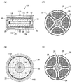
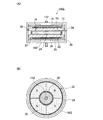
図1(A)は、本発明の第1実施例におけるコアレスブラシレスモータの構成を示す断面図である。このモータは、4極2相モータとして構成されている。
A. First embodiment:
FIG. 1A is a cross-sectional view showing the configuration of the coreless brushless motor in the first embodiment of the present invention. This motor is configured as a four-pole two-phase motor.
このモータ100は、略円盤状の第1と第2のステータ部10,20と、略円盤状のロータ部30とを有している。図1(B)に示すように、ロータ部30は、円環状に配置された4つの磁石32を有している。ロータ部30の中心は回転軸112に固定されている。磁石32の磁化方向は図1(A)の上下方向であり、図1(B)では紙面に垂直な方向である。磁石32の外周には、磁気ヨーク部材34が設けられている。
The
図1(C),(D)は、第1と第2のステータ部10,20をそれぞれ示している。第1のステータ部10は、個別にリング状に導線が巻き回された4つの電磁コイル12を有する。ここで、「リング状」とは、円形に限らず、図1(C)のコイル12のような略扇形や、楕円形状などの種々の形状を含む広い意味を有している。4つの電磁コイル12は、基板(回路基板)16に設置されている。また、基板16と電磁コイル12の間には、強磁性体で形成された磁気ヨーク部材18が設置されている。さらに、基板16には、ロータ部30の位置を検出するための磁気センサ14が設けられている。第2のステータ部20は、第1のステータ部10の電磁コイル12からずれた位置に設けられた4つの電磁コイル22を備えている。第2のステータ部20も、磁気センサ24と、基板(回路基板)26と、磁気ヨーク部材28と、磁気センサ24とを備えている。第1と第2のステータ部10,20は、モータ100のケーシング102(図1(A))に固定されている。
1C and 1D show the first and
なお、第1のステータ部10の4つの電磁コイル12を「A相コイル列12」とも呼び、第2のステータ部20の4つの電磁コイル22を「B相コイル列22」とも呼ぶ。また、A相コイル列12のための磁気センサ14を「A相磁気センサ14」とも呼び、B相コイル列22のための磁気センサ24を「B相磁気センサ24」とも呼ぶ。
The four
駆動制御回路(図示省略)は、A相磁気センサ14の出力を利用して、A相コイル列12を駆動するための第1の駆動信号を生成し、また、B相磁気センサ24の出力を利用して、B相コイル列22を駆動するための第2の駆動信号を生成する。磁気センサ14,24としては、アナログ出力を有するホールICを使用することができる。あるいは、2値又は多値のデジタル出力を有するセンサを利用してもよい。駆動制御回路としては、これらのセンサ14,24の出力を利用してPWM制御を行うことによって駆動信号を生成する回路を利用することができる。あるいは、センサ14,24の出力を増幅することによって駆動信号を生成する回路を利用することも可能である。
A drive control circuit (not shown) uses the output of the A-phase
A相コイル列12の4つのコイルは互いに同じ位相で駆動される。また、B相コイル列22の4つのコイルも互いに同じ位相で駆動される。ここで、「同じ位相で駆動される」とは、位相の差がπである場合も含んでいる。具体的には、A相コイル列12の4つのコイルは、対向するコイル同士の位相差が0となり、隣接するコイル同士の位相差がπとなるように駆動される。B相コイル列22の4つのコイルも同様である。また、A相コイル列12とB相コイル列22は、互いの位相差がπ/2となるように駆動される。
The four coils of the A
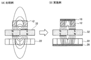
図2は、コイル列に設けられた磁気ヨーク部材の効果を示す説明図である。図2(A)に示す比較例ではコイル12,22に磁気ヨーク部材は設けられていない。一方、図2(B)に示す実施例では、コイル12,22の裏側(磁石32と反対の側)に磁気ヨーク部材18,28がそれぞれ設けられている。比較例では、磁石32から発生した磁力線がコイル12,22の裏側の空間にまで抜け出ており、磁束が必ずしもコイル12,22によって有効に利用されていないことが理解できる。一方、実施例では、磁石32から発生した磁力線がコイル12,22の裏側に設けられた磁気ヨーク部材18,28の中にほぼ保持されており、この結果、コイル12,22における磁束密度が高まっている。
FIG. 2 is an explanatory view showing the effect of the magnetic yoke member provided in the coil array. In the comparative example shown in FIG. 2A, no magnetic yoke member is provided on the
なお、一般にモータでは、磁石の磁界中に配置されたコイルに電流を流したときに発生するローレンツ力を利用して駆動力を発生させている。従って、コイルにおける磁界の強度を強く(すなわち磁束密度を高く)すれば、モータ効率が向上する。図2で示したように、本発明の実施例では、コイル12,22の磁石32とは反対側の位置に磁気ヨーク部材18,28を設けているので、コイル12,22における磁束密度が高まり、効率が向上することが理解できる。
In general, a motor generates a driving force by utilizing a Lorentz force generated when a current is passed through a coil arranged in a magnetic field of a magnet. Therefore, if the magnetic field strength in the coil is increased (that is, the magnetic flux density is increased), the motor efficiency is improved. As shown in FIG. 2, in the embodiment of the present invention, the
なお、本実施例のモータは、各コイル12,22の中心に磁性部材が設けられておらず、いわれるコアレスモータとして構成されている。コアレスモータでは、コギングが発生しない滑らかな動作を実現することが可能である。一方、通常のコアレスモータでは、必ずしも磁束密度が有効に利用されないために、モータ効率が低下することが多い。これに対して、本実施例のモータでは、コイル12,22の磁石32とは反対側の位置に磁気ヨーク部材18,28を設けているので、コアが無いことによる効率の低下をこれらの磁気ヨーク部材18,28によってかなり回復することが可能である。また、本実施例では、磁石列32の両側にコイル列12,22を設けることによって、磁石列32の両側の磁束の利用効率をさらに高めている。
In addition, the motor of a present Example is comprised as a coreless motor called the magnetic member not being provided in the center of each
図3は、A相コイル列12用の磁気ヨーク部材18の各種の形状を示す説明図である。なお、B相コイル列22用の磁気ヨーク部材28にも、これらと同じ形状を採用することが可能である。図3(A)は、A相コイル列12の形状を示している。各コイル12は、第1の外周円OC1と第1の内周円IC1とに挟まれた円環状の領域に巻かれている。また、個々のコイルの中空部分は、第2の外周円OC2と第2の内周円IC2とに挟まれた円環状の領域に存在する。なお、第1の外周円OC1は第2の外周円OC2よりも大きく、第1の内周円IC1は第2の内周円IC2よりも小さい。
FIG. 3 is an explanatory view showing various shapes of the
図3(A)に示す磁気ヨーク部材18aは、第2の外周円OC2と第2の内周円IC2との間に挟まれた円環状の領域に渡って磁性体が設けられた形状を有している。この磁気ヨーク部材18aは、図1に示したモータ100で使用されていた磁気ヨーク部材18と同じものである。この磁気ヨーク部材18aにおいて、個々のコイルの最外周の導線部分(第2の外周円OC2より外側の導線部分)と、最内周の導線部分(第2の内周円IC2より内側の導線部分)とに対応する領域に磁性体を設けないようにした理由は、これらの導線部分においては有効な駆動力が働かないからである。すなわち、コイルの最外周の導線部分と最内周の導線部分で発生する電磁力は、モータの動作方向とは垂直な方向(すなわち、回転軸112(図1(A))から放射状に伸びる方向)に働くだけであり、有効な駆動力とはならない。従って、これらの導線部分には、磁気ヨーク部材を設けないようにしても、効率はあまり低下する心配は無い。
The
図3(C)に示した磁気ヨーク部材18bは、第1の外周円OC1と第1の内周円IC1との間に挟まれた円環状の領域に渡って磁性体が設けられた形状を有している。なお、この磁気ヨーク部材18bでは、磁気センサ14(図1(C))を実装するための穴19(図3(B)では省略していた)が示されている。この磁気ヨーク部材18bは、図3(B)の磁気ヨーク部材18aよりも磁束の利用効率は高くなる点で好ましいが、鉄損が増加する。従って、鉄損の点では図3(B)に示した磁気ヨーク部材18aの方が好ましい。
The
図3(D)に示した磁気ヨーク部材18cは、第2の外周円OC2と第2の内周円IC2との間に挟まれた円環状の領域のうちの一部に磁性体が設けられ、他の部分では磁性体が省略されており、この結果、4つの島状の磁性体部分に分割されている。個々の磁性体部分は、隣接する一対のコイル12の隣り合う導線部分(図3(A)において2本の導線がほぼ平行に並んでいる部分)を覆う領域に対応付けられている。また、磁性体が省略されている部分は、各コイルのリング形状の中空部分に対応付けられている。図2で説明したように、磁気ヨーク部材18による磁束密度の増加が効率向上に寄与するのは、導線が存在する部分である。従って、図3(D)に示すように各コイルの中空部分に相当する領域において磁性体を省略するようにしても、効率はあまり低下することが無い。また、この磁気ヨーク部材18cでは、磁性体が少なくて済むので、鉄損が少なく、また、モータを軽量化することができる。
The
図3(E)に示した磁気ヨーク部材18dは、図3(D)の磁気ヨーク部材18cの4つの磁性体部分を互いに接続して一体としたものである。図3(F)に示した磁気ヨーク部材18eは、図3(E)の磁気ヨーク部材18dに磁気センサ14用の穴19を設けたものである。なお、磁気ヨーク部材の形状としては、上述したもの以外の種々の形状を採用することが可能である。
A
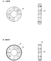
図4は、磁石列32(図1(B))の外周に設けられた磁気ヨーク部材34の効果を示す説明図である。図4(A)に示す比較例では円盤状に配列された磁石列32の外周に磁気ヨーク部材は設けられておらず、一方、図4(B)に示す実施例では、磁石32の外周に磁気ヨーク部材34が設けられている。図4(A)の右側(側面図)に示すように、比較例では、磁石列32の外周からさらに外側の空間(すなわち上下に)に伸びるように磁力線が発生している。これらの磁力線は、モータの駆動に有効に働かない無駄な磁力線である。一方、図4(B)に示した実施例では、円盤状に配列された磁石列32の外周から発生する磁力線が磁気ヨーク部材34の中にほぼ保持されており、この結果、鉄損などの損失の発生を低減することができる。但し、磁石列32用の磁気ヨーク部材34は省略してもよい。
FIG. 4 is an explanatory diagram showing the effect of the
以上のように、第1実施例では、各コアレスコイル列12,22の裏側(永久磁石と反対側)に、磁気ヨーク部材18,28を設けたので、コギングの発生を防止しつつ、磁石から発生する磁束密度の利用効率を向上させることができる。また、磁石列32の外周にも磁気ヨーク部材34を設けたので、損失の少ないモータを実現することができる。
As described above, in the first embodiment, since the
B.他の実施例:
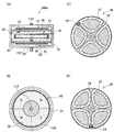
図5は、第2実施例におけるモータの構成を示している。このモータ100aは、図1(A)に示した第1実施例のモータ100の回路基板16と磁気ヨーク部材18の位置を逆にし、また、回路基板26と磁気ヨーク部材28の位置を逆にしたものであり、他の構成は第1実施例と同じである。すなわち、第2実施例のモータ100aでは、A相コイル列12と磁気ヨーク部材18は、回路基板16を挟んで回路基板16の異なる面に設置されている。B相コイル列22と磁気ヨーク部材28も、回路基板26を挟んで回路基板26の異なる面に設置されている。この第2実施例によっても、第1実施例と同様な効果を得ることができる。
B. Other examples:
FIG. 5 shows the configuration of the motor in the second embodiment. In the
図6は、第3実施例におけるモータの構成を示している。このモータ100bは、第1実施例のモータ100の磁石列32(図1(B))の内周側に第2の磁気ヨーク部材36を追加したものであり、他の構成は第1実施例と同じである。なお、図6(A)は図1(A)と同じである。また、第3実施例のコイル列12,22の構成は、図1(C),(D)に示したものと同じなので図示が省略されている。この第3実施例によっても、第1実施例と同様な効果を得ることができる。また、第3実施例では磁石列32の内周にも磁気ヨーク部材36を設けたので、より損失を低減することができる。
FIG. 6 shows the configuration of the motor in the third embodiment. This
図7(A)〜7(C)は、第4〜第6実施例におけるモータの構成を示している。図7(A)に示す第4実施例のモータ100cは、ケーシング102cを磁性体で構成したものであり、他の構成は第1実施例と同じである。ケーシング102cを磁性体で構成すれば、磁束の利用効率をより向上させることができる。図7(B)に示す第5実施例のモータ100dは、ケーシング102dを磁性体を含有した樹脂で構成したものであり、他の構成は第1実施例と同じである。この構成によっても、磁束の利用効率をより向上させることができる。図7(C)に示す第6実施例のモータ100eは、ケーシング102の内面に磁性体粉末層104を塗布したものである。この構成によっても、磁束の利用効率をより向上させることができる。これらの図7(A)〜7(C)に示した実施例のように、ケーシングに磁性体を含有する磁性体層を設けるようにすれば、磁束の外部への漏洩を防止することができる。
FIGS. 7A to 7C show the configuration of the motor in the fourth to sixth embodiments. In the motor 100c of the fourth embodiment shown in FIG. 7A, the
図8は、第7実施例におけるモータの構成を示している。このモータ100fは、2つの円盤状のロータ部30a,30bを有するダブルロータ構造を有している。2つのロータ30a,30bは、回転軸112に接続されており、互いに同じ構成を有している。図8(A)に示すように、このモータ100fは、上部モータ部100Uと、下部モータ部100Lとに分けられている。上部モータ部100Uは、第1のロータ部30aと、A相コイル列12を有する第1のステータ部10と、B相コイル列22aを有する第2のステータ部20aとで構成される。下部モータ部100Lは、第2のロータ部30bと、A相コイル列12を有する第1のステータ部10と、B相コイル列22bを有する第2のステータ部20bとで構成される。この説明から理解できるように、A相コイル列12は、上部モータ部100Uと下部モータ部100Lとで共用されている。2つのB相コイル列22a,22bは同じ構成を有している。
FIG. 8 shows the configuration of the motor in the seventh embodiment. The
なお、第7実施例では、モータの両側に設けられた2つのB相コイル列22a,22bには磁気ヨーク部材28が設けられているが、モータの軸方向の中央に設けられているA相コイル列12には磁気ヨーク部材が設けられていない。この理由は、A相コイル列12が上部モータ部100Uと下部モータ部100Lとで共用されるので、A相コイル列12には磁気ヨーク部材が無い方が好ましいからである。
In the seventh embodiment, the
この第7実施例のモータ100fは、第1実施例のモータ100の約2倍の駆動力を発生することができる。また、複数のコイル列12,22a,22bのうちで、モータの両端にあるコイル列22a,22bにはその外側に磁気ヨーク部材28が設けられているので、第1実施例と同様に磁束の利用効率を高めることができる。この説明から理解できるように、略円盤状のロータ部と、略円盤状のステータ部とが交互に配列された多重ロータ構造のモータでは、複数のステータ部のうちのモータの両端にあるステータ部のコイル列の外側に磁気ヨーク部材を設けると共に、内部にあるステータ部のコイル列には磁気ヨーク部材を設けないことが好ましい。
The
図9は、第8実施例としてのリニアモータの構成を示している。このリニアモータ1000は、固定ガイド部1100と、移動部1200とを備えている。固定ガイド部1100には、図9(A)に示すように、移動方向に沿って多数の永久磁石32が配列されている。移動部1200は、固定ガイド部1100を上下方向に挟むように構成されており、コイル列12,22が磁石列32の上と下にそれぞれ対向して設けられている。また、磁気コイルの間には、A相磁気センサ14とB相磁気センサ24が設けられている。各コイル列12,22には、磁気ヨーク部材18,28がそれぞれ設けられている。図9(B)に示すように、移動部1200には駆動制御部1250が設けられている。駆動制御部1250は、燃料電池などの自立的な電源装置(図示省略)を有している。固定ガイド部1100は、移動部1200を導くためのレール1120が設けられている。移動部1200は、ベアリング部1140によってレール1120に摺動可能に保持されている。本発明によるコアレスブラシレスモータは、このようなリニアモータとしても実現可能である。
FIG. 9 shows the configuration of a linear motor as the eighth embodiment. The
C.変形例:
なお、この発明は上記の実施例や実施形態に限られるものではなく、その要旨を逸脱しない範囲において種々の態様において実施することが可能であり、例えば次のような変形も可能である。
C. Variations:
The present invention is not limited to the above-described examples and embodiments, and can be implemented in various modes without departing from the gist thereof. For example, the following modifications are possible.
C1.変形例1:
上述した実施例では、磁石列の両側にコイル列が設けられていたが、磁石列の片側にのみコイル列を設けるようにしてもよい。但し、磁石列の両側にコイル列が設けるようにすれば、磁石の磁束をより有効に利用することができ、モータ効率を向上させることが可能である。
C1. Modification 1:
In the embodiment described above, the coil array is provided on both sides of the magnet array. However, the coil array may be provided only on one side of the magnet array. However, if the coil array is provided on both sides of the magnet array, the magnetic flux of the magnet can be used more effectively, and the motor efficiency can be improved.
C2.変形例2:
上述した第1ないし第7実施例では、円盤状のロータ及びステータを有する平面ロータ型モータを説明したが、本発明は、円筒型のロータ及びステータを有するモータなどの種々の構造のモータにも適用可能である。
C2. Modification 2:
In the first to seventh embodiments described above, the planar rotor type motor having the disk-shaped rotor and the stator has been described. However, the present invention is applicable to motors of various structures such as a motor having a cylindrical rotor and a stator. Applicable.
C3.変形例3:
上記実施例では、2相のコアレスブラシレスDCモータを説明したが、本発明はこれ以外の種々のコアレスブラシレスモータに適用可能である。例えば、極数と相数としては、それぞれ任意の整数を採用することができる。
C3. Modification 3:
Although the two-phase coreless brushless DC motor has been described in the above embodiment, the present invention can be applied to various other coreless brushless motors. For example, any integer can be adopted as the number of poles and the number of phases.
10…第1のステータ部(第1の構造部)
12…電磁コイル(A相コイル列)
14…磁気センサ(A相磁気センサ)
16…基板(回路基板)
18…磁気ヨーク部材
19…穴
20…第2のステータ部(第1の構造部)
22…電磁コイル(B相コイル列)
24…磁気センサ(B相磁気センサ)
26…回路基板
28…磁気ヨーク部材
30…ロータ部(第2の構造部)
32…永久磁石(磁石列)
34…磁気ヨーク部材
36…磁気ヨーク部材
100…モータ
100L…下部モータ部
100U…上部モータ部
102…ケーシング
104…磁性体粉末層
112…回転軸
1000…リニアモータ
1100…固定ガイド部
1120…レール
1140…ベアリング部
1200…移動部
1250…駆動制御部
10 ... 1st stator part (1st structure part)
12 ... Electromagnetic coil (A phase coil array)
14 ... Magnetic sensor (A phase magnetic sensor)
16 ... Board (circuit board)
18 ...
22 ... Electromagnetic coil (B phase coil array)
24 ... Magnetic sensor (B phase magnetic sensor)
26 ...
32 ... Permanent magnet (magnet array)
34 ...
Claims (4)
複数の電磁コイルを含むコイル列を有する円盤状の2つのステータ部と、
前記2つのステータ部の間に、円盤形状に配列され前記電磁コイルの数と同数の永久磁石を含む磁石列を有し、前記ステータ部との相対位置が変化可能な円盤状のロータ部と、
を備え、
前記コイル列には第1の磁気ヨーク部材が設けられており、前記第1の磁気ヨーク部材は、前記コイル列を挟んで前記磁石列とは反対側に設置されており、
前記磁石列には、前記磁石列の為す円盤の外周のみを覆う第2の磁気ヨーク部材が設けられており、
前記第1の磁気ヨーク部材は、分割されており、各電磁コイルのリング形状の中空部分に対応する第1の領域には磁性体が設けられておらず、隣接する各電磁コイル対の隣り合う導線部分に対応する第2の領域には磁性体が設けられており、
前記2つのステータ部のコイル列の電磁コイルは、互いの位相差がπ/2となるように駆動される、コアレスブラシレスモータ。 A coreless brushless motor,
Two disk-shaped stator portions having a coil array including a plurality of electromagnetic coils;
A disk-shaped rotor portion having a magnet row including permanent magnets arranged in a disk shape and having the same number as the number of the electromagnetic coils between the two stator portions; and a relative position of the stator portion being variable;
With
The coil row is provided with a first magnetic yoke member, and the first magnetic yoke member is disposed on the opposite side of the magnet row with the coil row interposed therebetween,
The magnet row is provided with a second magnetic yoke member that covers only the outer periphery of the disk formed by the magnet row,
The first magnetic yoke member is divided, and no magnetic body is provided in the first region corresponding to the ring-shaped hollow portion of each electromagnetic coil, and adjacent electromagnetic coil pairs are adjacent to each other. A magnetic body is provided in the second region corresponding to the conductor portion,
The coreless brushless motor, wherein the electromagnetic coils in the coil array of the two stator portions are driven such that the phase difference between them is π / 2.
前記第1の磁気ヨーク部材は、前記コイル列を保持するための基板に設置されており、
前記コイル列は、前記基板上に設置された前記第1の磁気ヨーク部材の上に設置されている、コアレスブラシレスモータ。 The coreless brushless motor according to claim 1,
The first magnetic yoke member is installed on a substrate for holding the coil row,
The coil array is a coreless brushless motor installed on the first magnetic yoke member installed on the substrate.
前記第1の磁気ヨーク部材は、前記コイル列を保持するための基板に設置されており、
前記コイル列と前記第1の磁気ヨーク部材とは前記基板の第1と第2の面に前記基板を挟んで設置されている、コアレスブラシレスモータ。 The coreless brushless motor according to claim 1,
The first magnetic yoke member is installed on a substrate for holding the coil row,
The core array brushless motor, wherein the coil array and the first magnetic yoke member are disposed on the first and second surfaces of the substrate with the substrate interposed therebetween.
前記ステータ部を少なくとも3つ有し、
前記ロータ部を少なくとも2つ有し、
前記ヨーク部材は、前記少なくとも3つのステータ部の少なくとも一部に設けられており、
前記ロータ部と前記ステータ部とは交互に配列され、前記少なくとも3つのステータ部のうちの2つは、前記ロータ部と前記ステータ部の配列の両端に配置されており、
前記第1の磁気ヨーク部材は、前記配列の両端に配置されたステータ部のみに設けられ、前記配列の両端以外に配置されたステータ部には設けられていない、ことを特徴とする、コアレスブラシレスモータ。 The coreless brushless motor according to any one of claims 1 to 3 ,
Having at least three stator parts;
Having at least two of the rotor parts;
The yoke member is provided on at least a part of the at least three stator portions,
The rotor parts and the stator parts are alternately arranged, and two of the at least three stator parts are arranged at both ends of the arrangement of the rotor parts and the stator parts,
The coreless brushless, wherein the first magnetic yoke member is provided only in a stator portion disposed at both ends of the array, and is not provided in a stator portion disposed outside the both ends of the array. motor.
Priority Applications (1)
| Application Number | Priority Date | Filing Date | Title |
|---|---|---|---|
| JP2011152447A JP5403003B2 (en) | 2011-07-11 | 2011-07-11 | Coreless brushless motor |
Applications Claiming Priority (1)
| Application Number | Priority Date | Filing Date | Title |
|---|---|---|---|
| JP2011152447A JP5403003B2 (en) | 2011-07-11 | 2011-07-11 | Coreless brushless motor |
Related Parent Applications (1)
| Application Number | Title | Priority Date | Filing Date |
|---|---|---|---|
| JP2006230802A Division JP4984745B2 (en) | 2006-08-28 | 2006-08-28 | Coreless brushless motor |
Publications (2)
| Publication Number | Publication Date |
|---|---|
| JP2011205893A JP2011205893A (en) | 2011-10-13 |
| JP5403003B2 true JP5403003B2 (en) | 2014-01-29 |
Family
ID=44881889
Family Applications (1)
| Application Number | Title | Priority Date | Filing Date |
|---|---|---|---|
| JP2011152447A Expired - Fee Related JP5403003B2 (en) | 2011-07-11 | 2011-07-11 | Coreless brushless motor |
Country Status (1)
| Country | Link |
|---|---|
| JP (1) | JP5403003B2 (en) |
Cited By (1)
| Publication number | Priority date | Publication date | Assignee | Title |
|---|---|---|---|---|
| EP3454459A4 (en) * | 2016-05-04 | 2019-12-25 | Yu, Renwei | Efficient laminated coreless generator and manufacturing method therefor |
Families Citing this family (2)
| Publication number | Priority date | Publication date | Assignee | Title |
|---|---|---|---|---|
| JP5963436B2 (en) * | 2011-12-21 | 2016-08-03 | 株式会社ヴァレオジャパン | Electric compressor |
| JP5965527B1 (en) * | 2015-11-09 | 2016-08-10 | 新明工業株式会社 | Coilless motor |
Family Cites Families (5)
| Publication number | Priority date | Publication date | Assignee | Title |
|---|---|---|---|---|
| JPS61141979U (en) * | 1985-02-22 | 1986-09-02 | ||
| JPH01110044A (en) * | 1987-10-23 | 1989-04-26 | Shicoh Eng Co Ltd | Disc type single phase brushless motor |
| JP3207251B2 (en) * | 1992-07-10 | 2001-09-10 | 株式会社東芝 | Axial gap rotating electric machine |
| JPH09139016A (en) * | 1995-11-16 | 1997-05-27 | Tokyo Parts Ind Co Ltd | Rotor of spindle motor |
| JP2001255485A (en) * | 2000-03-10 | 2001-09-21 | Fuji Xerox Co Ltd | Light deflector |
-
2011
- 2011-07-11 JP JP2011152447A patent/JP5403003B2/en not_active Expired - Fee Related
Cited By (1)
| Publication number | Priority date | Publication date | Assignee | Title |
|---|---|---|---|---|
| EP3454459A4 (en) * | 2016-05-04 | 2019-12-25 | Yu, Renwei | Efficient laminated coreless generator and manufacturing method therefor |
Also Published As
| Publication number | Publication date |
|---|---|
| JP2011205893A (en) | 2011-10-13 |
Similar Documents
| Publication | Publication Date | Title |
|---|---|---|
| JP5491484B2 (en) | Switched reluctance motor | |
| JP5033552B2 (en) | Axial gap type coreless rotating machine | |
| US7569962B2 (en) | Multi-phase brushless motor with reduced number of stator poles | |
| US20100289370A1 (en) | Synchronous motor having 12 stator teeth and 10 rotor poles | |
| JP5703168B2 (en) | motor | |
| JP2013215021A (en) | Electromagnetic induction device | |
| JP6406355B2 (en) | Double stator type rotating machine | |
| JP2009509488A (en) | Electric drive machine | |
| JP2016538817A (en) | Transverse flux type electric machine | |
| JP2014155373A (en) | Multi-gap rotary electric machine | |
| JP2008252979A (en) | Axial-gap type rotating machine | |
| JP2010284035A (en) | Permanent magnet rotating electrical machine | |
| JP5403003B2 (en) | Coreless brushless motor | |
| JP2011223676A (en) | Permanent magnet type motor | |
| JP2012249347A (en) | Rotor of axial gap rotary electric machine | |
| JP2014192942A (en) | Rotary machine | |
| JP2015512241A (en) | Electric machine | |
| JP4303579B2 (en) | Three-dimensional stator structure rotating machine | |
| JP2014192951A (en) | Dynamo-electric machine, electric motor unit and generator unit | |
| JP2012019605A (en) | Permanent magnet rotating electrical machine | |
| JP6415029B2 (en) | Electromagnetic induction device | |
| JP4984745B2 (en) | Coreless brushless motor | |
| JP6543239B2 (en) | Stacked motor and stacked generator | |
| JP5540482B2 (en) | Actuator | |
| JP2011151914A (en) | Stator for brushless motors and brushless motor |
Legal Events
| Date | Code | Title | Description |
|---|---|---|---|
| A521 | Written amendment |
Free format text: JAPANESE INTERMEDIATE CODE: A523 Effective date: 20110801 |
|
| A621 | Written request for application examination |
Free format text: JAPANESE INTERMEDIATE CODE: A621 Effective date: 20110801 |
|
| A977 | Report on retrieval |
Free format text: JAPANESE INTERMEDIATE CODE: A971007 Effective date: 20130228 |
|
| A131 | Notification of reasons for refusal |
Free format text: JAPANESE INTERMEDIATE CODE: A131 Effective date: 20130312 |
|
| A521 | Written amendment |
Free format text: JAPANESE INTERMEDIATE CODE: A523 Effective date: 20130502 |
|
| A01 | Written decision to grant a patent or to grant a registration (utility model) |
Free format text: JAPANESE INTERMEDIATE CODE: A01 Effective date: 20131001 |
|
| A61 | First payment of annual fees (during grant procedure) |
Free format text: JAPANESE INTERMEDIATE CODE: A61 Effective date: 20131014 |
|
| S531 | Written request for registration of change of domicile |
Free format text: JAPANESE INTERMEDIATE CODE: R313531 |
|
| R350 | Written notification of registration of transfer |
Free format text: JAPANESE INTERMEDIATE CODE: R350 |
|
| LAPS | Cancellation because of no payment of annual fees |
