JP6543239B2 - Stacked motor and stacked generator - Google Patents
Stacked motor and stacked generator Download PDFInfo
- Publication number
- JP6543239B2 JP6543239B2 JP2016234887A JP2016234887A JP6543239B2 JP 6543239 B2 JP6543239 B2 JP 6543239B2 JP 2016234887 A JP2016234887 A JP 2016234887A JP 2016234887 A JP2016234887 A JP 2016234887A JP 6543239 B2 JP6543239 B2 JP 6543239B2
- Authority
- JP
- Japan
- Prior art keywords
- rotor
- stator
- magnetic flux
- flux density
- motor
- Prior art date
- Legal status (The legal status is an assumption and is not a legal conclusion. Google has not performed a legal analysis and makes no representation as to the accuracy of the status listed.)
- Active
Links
Images


Description
本発明は垂直方向において円盤状の固定子と円盤状の回転子を同芯円上に交互に積層した積層型モーター及び積層型発電機に関する。さらに言えば、固定子と回転子を垂直方向に交互に積層することにより磁束密度を大きくし、従来のモーターよりも高出力を実現することができ、または従来の発電機よりも発電効率を向上させると共に、磁場解析に基づいた垂直方向における永久磁石の配置等により磁束密度分布を制御することで漏れ磁束の発生が殆ど無い積層型モーター、及び積層型発電機に関する。 The present invention relates to a laminated motor and a laminated generator in which a disk-shaped stator and a disk-shaped rotor are alternately laminated on a concentric circle in the vertical direction. Furthermore, by alternately stacking the stator and the rotor in the vertical direction, the magnetic flux density can be increased, and a higher output can be realized than in the conventional motor, or the power generation efficiency can be improved over the conventional generator. The present invention relates to a laminated motor and a laminated generator in which the occurrence of a leakage flux is hardly generated by controlling the magnetic flux density distribution by the arrangement of permanent magnets in the vertical direction based on magnetic field analysis and the like.
モーターの出力を向上させるためには、トルク(回転力)上げる必要がある。トルクを上げるには、磁界強度を上げる、電流値を上げる、磁束密度を上げる等の方策が考えられる。ラジアルギャップ型モーターにおいては、磁界強度は電流と巻き数に比例することから、通常はコイルの巻き数を増やしトルクを上げようとするが、その分、永久磁石とコイルの隙間(ギャップ)が大きくなり過ぎて効率が低下し、コギングトルク(トルク変動による悪影響)により効率が低下してしまう。さらに、電流を大きくすると導線の電気抵抗(=エネルギーの損失)による発熱が起こり、導線同士の絶縁が維持できなくなることから、モーターを空気や水などの冷媒により冷却する必要があり、このことも効率を低下させている。 In order to improve the output of the motor, it is necessary to increase the torque (rotational force). To increase the torque, it is conceivable to increase the magnetic field strength, increase the current value, increase the magnetic flux density, or the like. In a radial gap type motor, since the magnetic field strength is proportional to the current and the number of turns, usually the number of turns of the coil is increased to try to increase the torque, but the gap between the permanent magnet and the coil is large. If so, the efficiency decreases due to the cogging torque (the adverse effect due to the torque fluctuation). Furthermore, if the current is increased, heat is generated due to the electrical resistance (= loss of energy) of the conducting wire, and insulation between the conducting wires can not be maintained, so it is necessary to cool the motor with a refrigerant such as air or water. It is reducing the efficiency.
一方、アキシャルギャップ型モーターにおいては、コギングトルク(トルク変動による悪影響)が発生しないことから、ラジアルギャップ型モーターより効率が良いものの、コイルの巻き方・巻き数、コイルと永久磁石の関係、発熱等の課題も多いし、従来型アキシャルギャップ型モーター(特開2002−320364)において、固定子と回転子を其々一層のみで実現しようとすると、軸線の垂直方向に広がる方向に拡大することになり小型化することができない。 On the other hand, in an axial gap type motor, cogging torque (a bad influence by torque fluctuation) does not occur, though it is more efficient than a radial gap type motor, coil winding method / number of turns, relationship between coil and permanent magnet, heat generation etc. In the conventional axial gap type motor (Japanese Patent Application Laid-Open No. 2002-320364), if it is intended to realize the stator and the rotor only by one layer, they will be expanded in the direction in which the axis extends in the vertical direction. It can not be miniaturized.
また、ラジアルギャップ型モーターもアキシャルギャップ型モーターも、永久磁石を厚くすることで磁束密度を大きくしようとするとヨークを兼ねたモーターケースも重量が増加し、さらに、ヨーク側へ流れ出る磁束は利用されることがない。そのため、磁石自体の磁束密度を上げるための開発が主流になって行くと思われるモーター技術の流れにおいて、更なる強磁性磁石の開発にも限度があるものと考えられる。尚、モーターと発電機は構造が同じであるので、モーターの出力向上は、発電機の発電効率の向上に密接な関連があると言える。 In both the radial gap type motor and the axial gap type motor, increasing the magnetic flux density by thickening the permanent magnet also increases the weight of the motor case that also serves as the yoke, and the magnetic flux flowing out to the yoke side is used I have not. Therefore, it is thought that there is a limit to the development of further ferromagnetic magnets in the flow of motor technology where development for increasing the magnetic flux density of the magnet itself is becoming mainstream. Incidentally, since the motor and the generator have the same structure, it can be said that the improvement of the output of the motor is closely related to the improvement of the power generation efficiency of the generator.
一方、エネルギー問題や少子高齢化社会といった今後の私たちの生活を支える技術として、ハイブリッドカーや電気自動車(輸送用車両、工作機械等)、介護や人の生活支援等を行うロボットの開発が進められている。これらの製品を開発するためには、現状よりも小型で扱い易く、エネルギー効率が良く、高出力であるモーターが必要不可欠となってくると言われている。現在最も普及している電磁モーターは高出力化に伴い重量が増し、発熱量が増すために効率が悪くなるという特徴があり、将来的に自動車やロボット等に使用するモーターとしては大きな欠点となってしまうことになる。同様な観点で見れば、モーターと発電機は構造が同じであるので、モーターの高出力小型化は、発電機の発電効率の向上に密接な関連があると言える。 On the other hand, development of hybrid cars and electric vehicles (transportation vehicles, machine tools, etc.), robots that provide nursing care and human life support, etc. is advanced as technology to support our future life such as energy problems and aging society It is done. In order to develop these products, it is said that motors smaller in size, easier to handle, energy efficient, and high output than those in the present situation will be indispensable. At present, the most popular electromagnetic motors are characterized by the fact that their weight increases with higher output and their heat generation amount increases, resulting in poor efficiency, which is a major drawback for motors used in automobiles and robots in the future. It will From the same point of view, since the motor and the generator have the same structure, it can be said that the high output miniaturization of the motor is closely related to the improvement of the power generation efficiency of the generator.
特許文献1には、「軸線及び前記軸線に沿って間隔をおいて配置された複数の層を有し、それぞれの層が、前記軸線に関して一般的に放射方向に向けられた引き伸ばされた導線部を有する巻き線をもつ導線相集合体を含む固定子と、前記固定子と同軸の軸線を有する回転子であって、回転可能に前記固定子につながれた軸と、透磁率、軸線、第1及び第2の面及び複数の扇形の極、厚さを定める前記面の間の軸方向の距離を有し、前記第1の面のそれぞれの極が前記第1の面の横方向に隣接した極と反対の極性であり、前記第2の面の軸方向に隣接した極と反対の極性である、前記軸と同軸につながれた2つの環状の外部磁石と、それぞれが透磁率、軸線、第1及び第2の面及び複数の扇形の極、厚さを定める前記面の間の軸方向の距離を有し、前記第1の面のそれぞれの極が前記第1の面の横方向に隣接した極と反対の極性であり、前記第2の面の軸方向に隣接した極と反対の極性である、前記外部磁石の間に前記軸と同軸につながれた少なくとも1つの環状の中央磁石とを備え、それぞれの磁石のそれぞれの扇形の前記第1及び第2の面の1つが、反対の極性を有する隣接した磁石の極に対して固定して整列された極を有する前記回転子と、それぞれが前記外部磁石の前記透磁率より大きい透磁率を有し、外部磁石の前記第1及び第2の面の1つに隣接して配置された2つの端キャップとを備えたモーター/発電機。(特許文献1:請求項1そのまま)」が開示されている。即ち、固定子と回転子を、垂直方向における間隔を取りつつ積層した構造を有するモーター/発電機(特許文献1:発明の名称)が開示されている。 Patent document 1 discloses “an axis line and a plurality of layers spaced along the axis line, each of which is an elongated wire section generally directed in the radial direction with respect to the axis line. A stator including a wire phase assembly having windings having a winding, and a rotor having an axis coaxial with the stator, the shaft rotatably coupled to the stator, permeability, an axis, a first And a second surface and a plurality of fan-shaped poles, with an axial distance between said surfaces defining a thickness, each pole of said first surface being laterally adjacent to said first surface Two annular external magnets coaxially connected to said axis, of opposite polarity to the pole and of opposite polarity to the axially adjacent pole of said second surface, each having a permeability, an axis, a second Have an axial distance between the first and second faces and the plurality of sector poles, the faces defining the thickness The respective pole of the first surface being of opposite polarity to the laterally adjacent pole of the first surface and of opposite polarity to the axially adjacent pole of the second surface, At least one annular central magnet coaxially connected with said axis between the outer magnets, one of said first and second faces of each sector of each magnet being adjacent having the opposite polarity One of the first and second faces of the outer magnet, the rotor having a pole fixedly aligned with the pole of the magnet, each having a permeability greater than the permeability of the outer magnet, each of the first and second faces of the outer magnet A motor / generator with two end caps arranged adjacent to one another (US Pat. No. 5,648,869, claim 1 as it is). That is, there is disclosed a motor / generator having a structure in which a stator and a rotor are stacked at intervals in the vertical direction (Patent Document 1: title of the invention).
特許文献1に係るモーター/発電機(特許文献1:発明の名称)は、確かに固定子と回転子を、間隔をおいて垂直方向に積層したモーター(特許文献1:図3等参照)であるが、固定子と回転子を垂直方向に交互に積層することにより積層された永久磁石の磁束線分布等について何らの工夫もされておらず、いわゆる漏れ磁束についての対策が全く為されていない。このため、特に磁束が外部に漏れてしまうことで何らかの影響を受けてしまうような精密機器等における使用には適していないという欠点があるものと考えられる。 The motor / generator according to Patent Document 1 (Patent Document 1: Title of Invention) is certainly a motor in which a stator and a rotor are vertically stacked at an interval (Patent Document 1: see FIG. 3 etc.) Although there is no device for the flux line distribution of permanent magnets stacked by alternately stacking the stator and the rotor in the vertical direction, there is no countermeasure against so-called leakage flux at all. . For this reason, it is considered that there is a disadvantage that it is not suitable for use in precision equipment or the like, which is affected in particular by leakage of magnetic flux to the outside.
本発明の目的は、固定子と回転子を垂直方向に交互に積層することにより磁束密度を大きくし、従来のモーターよりも高出力を実現することができると共に、磁場解析に基づいた垂直方向における永久磁石の配置等により磁束密度分布を制御することで漏れ磁束が殆ど無い積層型モーターを提供することにある。 The object of the present invention is to increase the magnetic flux density by alternately laminating the stator and the rotor in the vertical direction, and achieve higher output than the conventional motor, and in the vertical direction based on the magnetic field analysis An object of the present invention is to provide a laminated motor having almost no leakage flux by controlling the magnetic flux density distribution by the arrangement of permanent magnets and the like.
上記課題を解決するために、請求項1に記載された発明は、複数の中空円盤状の固定子と複数の中空円盤状の回転子を同芯円上に交互に積層することにより形成する固定子と回転子と中心軸を備えた積層型モーターであって、前記回転子は前記中心軸の外周に固定されて所定の間隔で同心円上に設置されており、前記固定子は前記回転子と前記回転子の間に同心円上に設置されており、前記固定子は周方向に沿って所定の間隔を置いて配置された複数の巻線コイルを備えており、前記回転子は、周方向に沿って所定の間隔を置いて配置された複数の永久磁石を備えており、前記複数の永久磁石は、垂直方向において磁束密度が中心に向かって次第に大きくなり、積層の中心部において最大値をとるように配置する、或いは、垂直方向において積層の両端部の磁束密度を最大にして、それ以外の部分において磁束密度は小さくなるように配置する積層型モーターであることを特徴とするものである。 In order to solve the above problems, the invention described in claim 1 is a fixing formed by alternately laminating a plurality of hollow disk-shaped stators and a plurality of hollow disk-shaped rotors on concentric circles. It is a laminated motor comprising a rotor, a rotor and a central axis, wherein the rotor is fixed to the outer periphery of the central axis and concentrically installed at a predetermined interval, and the stator is The stator is concentrically disposed between the rotors, and the stator includes a plurality of winding coils disposed at predetermined intervals along the circumferential direction, and the rotor is circumferentially arranged. The plurality of permanent magnets are disposed at predetermined intervals along the longitudinal direction, and the plurality of permanent magnets have magnetic flux density gradually increasing toward the center in the vertical direction, and take a maximum value at the center of the stack. Arranged in the vertical direction or And the magnetic flux density at both ends of the layer to a maximum, and is characterized in that the magnetic flux density is laminated motor arranged to be small in the other parts.
請求項2に記載された発明は、複数の中空円盤状の固定子と複数の中空円盤状の回転子を同芯円上に交互に積層することにより形成する積層型モーターであって、前記固定子は所定の間隔を置いて同心円上に設置されており、前記回転子は前記固定子と前記固定子の間に同心円上に設置されており、前記固定子は周方向に沿って所定の間隔を置いて配置された複数の巻線コイルを備えており、前記回転子は、周方向に沿って所定の間隔を置いて配置された複数の永久磁石を備えており、前記複数の永久磁石は、垂直方向において磁束密度が中心に向かって次第に大きくなり、積層の中心部において最大値をとるように配置する、或いは、垂直方向において積層の両端部の磁束密度を最大にして、それ以外の部分において磁束密度は小さくなるように配置する積層型モーターであることを特徴とするものである。 The invention described in claim 2 is a laminated motor formed by alternately laminating a plurality of hollow disk-shaped stators and a plurality of hollow disk-shaped rotors on concentric circles, The rotors are concentrically disposed at a predetermined distance, and the rotor is concentrically disposed between the stator and the stator, and the stators are circumferentially spaced by a predetermined distance. The rotor is provided with a plurality of permanent magnets arranged at predetermined intervals along the circumferential direction, the plurality of permanent magnets being The magnetic flux density is gradually increased toward the center in the vertical direction, and arranged so as to take the maximum value in the central portion of the stack, or the magnetic flux density at both ends of the stack is maximized in the vertical direction. Magnetic flux density decreases at It is characterized in that it is laminated motor that urchin arrangement.
請求項3に記載された発明は、複数の中空円盤状の固定子と複数の中空円盤状の回転子を同芯円上に交互に積層することにより形成する固定子と回転子と中心軸を備えた積層型発電機であって、前記回転子は前記中心軸の外周に固定されて所定の間隔で同心円上に設置されており、前記固定子は前記回転子と前記回転子の間に同心円上に設置されており、
前記固定子は周方向に沿って所定の間隔を置いて配置された複数の巻線コイルを備えており、前記回転子は、周方向に沿って所定の間隔を置いて配置された複数の永久磁石を備えており、前記複数の永久磁石は、垂直方向において磁束密度が中心に向かって次第に大きくなり、積層の中心部において最大値をとるように配置する、或いは、垂直方向において積層の両端部の磁束密度を最大にして、それ以外の部分において磁束密度は小さくなるように配置する積層型発電機であることを特徴とするものである。
The invention described in claim 3 is a stator, a rotor and a central axis formed by alternately laminating a plurality of hollow disk-shaped stators and a plurality of hollow disk-shaped rotors on concentric circles. In the laminated generator, the rotor is fixed to the outer periphery of the central axis and concentrically installed at a predetermined interval, and the stator is a concentric circle between the rotor and the rotor. are installed above,
The stator includes a plurality of winding coils disposed at predetermined intervals along the circumferential direction, and the rotor is provided with a plurality of permanent magnets disposed at predetermined intervals along the circumferential direction. The magnets are provided, and the plurality of permanent magnets are arranged such that the magnetic flux density gradually increases toward the center in the vertical direction and takes a maximum value at the center of the stack, or both ends of the stack in the vertical direction It is characterized in that it is a laminated generator arranged so as to maximize the magnetic flux density of (1) and to decrease the magnetic flux density in the other parts .
請求項3に記載された発明は、複数の中空円盤状の固定子と複数の中空円盤状の回転子を同芯円上に交互に積層することにより形成する積層型発電機であって、前記固定子は所定の間隔を置いて同心円上に設置されており、前記回転子は前記固定子と前記固定子の間に同心円上に設置されており、前記固定子は周方向に沿って所定の間隔を置いて配置された複数の巻線コイルを備えており、前記回転子は、周方向に沿って所定の間隔を置いて配置された複数の永久磁石を備えており、前記複数の永久磁石は、垂直方向において磁束密度が中心に向かって次第に大きくなり、積層の中心部において最大値をとるように配置する、或いは、垂直方向において積層の両端部の磁束密度を最大にして、それ以外の部分において磁束密度は小さくなるように配置する積層型発電機であることを特徴とするものである。 The invention described in claim 3 is a laminated generator formed by alternately laminating a plurality of hollow disk-shaped stators and a plurality of hollow disk-shaped rotors on concentric circles, The stators are concentrically disposed at predetermined intervals, and the rotor is concentrically disposed between the stators and the stators, and the stators are circumferentially formed. The rotor comprises a plurality of spaced apart wound coils, and the rotor comprises a plurality of permanent magnets arranged at predetermined intervals along a circumferential direction, the plurality of permanent magnets Is arranged so that the magnetic flux density gradually increases toward the center in the vertical direction and takes a maximum value at the center of the stack, or the flux density at the both ends of the stack is maximized in the vertical direction, The magnetic flux density will be smaller in the part It is characterized in that it is laminated generator placed.
請求項5に記載された発明は、請求項1乃至請求項4のいずれかに記載した発明において、前記固定子は周方向に沿って所定の間隔を置いて配置された複数の永久磁石を備えており、前記回転子は、周方向に沿って所定の間隔を置いて配置された複数の巻線コイルを備えている積層型モーターまたは積層型発電機であることを特徴とするものである。 In the invention described in claim 5, in the invention described in any one of claims 1 to 4, the stator is provided with a plurality of permanent magnets arranged at predetermined intervals along the circumferential direction. The rotor is a laminated motor or a laminated generator including a plurality of winding coils disposed at predetermined intervals along a circumferential direction.
請求項6に記載された発明は、請求項1乃至請求項5のいずれかに記載した発明において、前記固定子と前記固定子との間に生じる隙間の外端部にリング形状のスペーサーリングを前記固定子と一体化させつつ介在させる積層型モーターまたは積層型発電機であることを特徴とするものである。 In the invention described in claim 6, in the invention described in any one of claims 1 to 5, a ring-shaped spacer ring is provided at the outer end of the gap generated between the stator and the stator. It is characterized in that it is a laminated motor or a laminated generator interposed while being integrated with the stator.
請求項7に記載された発明は、請求項1乃至請求項5のいずれかに記載した発明において、前記回転子と前記回転子との間に生じる隙間の外端部にリング形状のスペーサーリングを前記回転子と一体化させつつ介在させる積層型モーターまたは積層型発電機であることを特徴とするものである。 In the invention described in claim 7, in the invention described in any one of claims 1 to 5, a ring-shaped spacer ring is provided at the outer end of the gap generated between the rotor and the rotor. It is characterized in that it is a laminated motor or a laminated generator interposed while being integrated with the rotor.
本発明の特徴を端的に言えば、複数の中空円盤状の固定子と複数の中空円盤状の回転子を同芯円上に交互に積層することにより形成する積層型モーター、或いは、複数の中空円盤状の固定子と複数の中空円盤状の回転子を同芯円上に交互に積層することにより形成する積層型発電機である。本発明に係る積層型モーター、及び積層型発電機は以下に記載するような様々な構成を取ることができる。即ち、中心軸等に固定されたインナー側が回転子になり中心軸等に固定されないアウター側が固定子になる構成と(インナー回転仕様)、逆に、中心部筒状空間に設置した円柱構造物等に固定されたインナー側が固定子になりアウター側が回転子になる構成(アウター回転仕様)がある。さらに、回転子に永久磁石を配置し固定子に巻線コイルを配置する構成と、逆に、固定子に永久磁石を配置し回転子に巻線コイルを配置する構成がある。本発明は、上記に記載した構成の組み合わせを考慮すると種々のバリエーションを採ることができる。 Briefly speaking, the features of the present invention are a laminated motor formed by alternately laminating a plurality of hollow disk-shaped stators and a plurality of hollow disk-shaped rotors on concentric circles, or a plurality of hollows This is a laminated generator formed by alternately laminating a disk-shaped stator and a plurality of hollow disk-shaped rotors on concentric circles. The laminated motor and the laminated generator according to the present invention can have various configurations as described below. That is, a configuration in which the inner side fixed to the central axis etc. becomes the rotor and the outer side not fixed to the central axis becomes the stator (inner rotation specification), conversely, a cylindrical structure etc. installed in the central cylindrical space The inner side fixed to is the stator and the outer side is the rotor (outer rotation specification). Furthermore, there is a configuration in which permanent magnets are disposed in the rotor and winding coils are disposed in the stator, and conversely, there is a configuration in which permanent magnets are disposed in the stator and winding coils are disposed in the rotor. The present invention can take various variations in consideration of the combination of the configurations described above.
上記のバリエーションの中から一例として、インナー回転仕様で回転子に巻線コイル(固定子に永久磁石)が配置されているものについて、本発明の効果を説明すると、複数の中空円盤状の回転子が中心軸の外周に所定の間隔(垂直方向)を取りつつ同心円上に固定されている。それぞれの中空円盤状の回転子は、周方向に沿って所定の間隔を置いて配置された複数の巻線コイルを備えている。 As an example from among the above variations, the effect of the present invention will be described for an inner rotation specification in which a winding coil (permanent magnet on a stator) is disposed in a rotor, a plurality of hollow disk-shaped rotors Are fixed concentrically while taking a predetermined distance (vertical direction) on the outer periphery of the central axis. Each hollow disk-shaped rotor includes a plurality of winding coils disposed at predetermined intervals along the circumferential direction.
一方、複数の中空円盤状の固定子が中空円盤状の回転子と中空円盤状の回転子の間に同心円上に設置されており、それぞれの固定子は、周方向に沿って所定の間隔を置いて配置された複数の永久磁石を備えている。このように固定子と回転子を垂直方向に交互に積層すること(永久磁石のS極とN極が垂直方向に交互に来るように配置)により個々の永久磁石から出る磁力線を垂直方向に合成させることにより磁束密度を大きくし、従来のモーターよりも高出力を実現することができるようになったし、従来の発電機よりも発電効率を向上させることができるようになった。 On the other hand, a plurality of hollow disk-shaped stators are concentrically disposed between the hollow disk-shaped rotor and the hollow disk-shaped rotor, and each stator has a predetermined interval along the circumferential direction. It has a plurality of permanent magnets placed and placed. In this manner, by alternately stacking the stator and the rotor in the vertical direction (arranged such that the south pole and the north pole of the permanent magnet are alternately arranged in the vertical direction), the magnetic field lines emerging from the individual permanent magnets are combined in the vertical direction By doing this, it is possible to increase the magnetic flux density, to realize higher output than the conventional motor, and to improve the power generation efficiency more than the conventional generator.
また本発明によれば、垂直方向に磁束密度が異なる永久磁石を配置(永久磁石のS極とN極が垂直方向に交互に来るように配置)した積層型モーター、及び積層型発電機であるので、磁束密度を大きくし、従来のモーターよりも高出力を実現すること(従来の発電機よりも発電効率を向上させること)ができると共に、磁場解析に基づいた垂直方向における磁束密度の異なる永久磁石の配置等により磁力線分布を制御することで漏れ磁束が殆ど無い積層型モーター、及び積層型発電機を実現することができるようになった。 Further, according to the present invention, there are provided a laminated motor and a laminated generator in which permanent magnets having different magnetic flux densities in the vertical direction are arranged (arranged such that the south pole and the north pole of the permanent magnet are alternately arranged in the vertical direction). Therefore, it is possible to increase the magnetic flux density and achieve higher output than the conventional motor (to improve the power generation efficiency over the conventional generator), and to change the permanent magnet having different magnetic flux density in the vertical direction based on magnetic field analysis. By controlling the distribution of magnetic lines of force by the arrangement of magnets, etc., it has become possible to realize a laminated motor and a laminated generator having almost no leakage flux.
さらに、垂直方向に積層された中空円盤状の固定子(または回転子)と中空円盤状の固定子(または回転子)との間に生じる隙間の外端部にリング形状のスペーサーリングを固定子(または回転子)と一体化させつつ介在させる積層型モーター、及び積層型発電機であるので、リング形状のスペーサーリングの厚さをそれぞれの層によって変化させることで磁力線分布を制御し漏れ磁束が殆ど無い積層型モーター、及び積層型発電機を実現することができるようになった。 Furthermore, a ring-shaped spacer ring is formed at the outer end of the gap formed between the vertically stacked hollow disk stator (or rotor) and the hollow disk stator (or rotor). Since it is a laminated motor and a laminated generator that are integrated while being integrated with (or a rotor), the magnetic flux line is controlled by changing the thickness of the ring-shaped spacer ring depending on each layer, and the leakage flux is It has become possible to realize a laminated motor and a laminated generator that have almost nothing.
積層型のモーターにすることにより、一層で発生させるべきトルクを複数の層で分担することになり小型化が可能となる。モーターを小型化することができれば様々な用途の広がる可能性が出てくると考えられる。昨今は地球温暖化の原因として、CO2排出の抑制が叫ばれるようになり、今後の世の中の流れとして、自然エネルギー活用も含めた、効率の良い、アキシャルギャップモーターの開発が主流となると考えられる。 By forming a laminated motor, torque to be generated in one layer can be shared by a plurality of layers, and miniaturization can be achieved. If the motor can be miniaturized, it is considered that the possibility of expanding various applications will come out. Nowadays, as the cause of global warming, the suppression of CO 2 emissions is called for, and it is thought that the development of efficient axial gap motors, including the use of natural energy, will be the mainstream as a future trend in the world .
さらに積層型のモーターにすることにより、導線の巻き数も各層其々で変化させることができることから、モーターのトルク出力も現状のモーターよりも細かく制御できるようになったので、製品の設計上の問題等により、モーターの出力において過不足が生じた場合も、回転子と固定子の積層枚数を調整することによる対応が可能となり、モーターそのものを交換しなくてもよく、設計変更にかかる工数も削減できるようになる。 Furthermore, by using a laminated motor, the number of turns of the conductor can be changed in each layer, and the torque output of the motor can now be controlled more finely than the current motor, so the design of the product Even if there is an excess or deficiency in the motor output due to a problem, etc., it is possible to cope with this by adjusting the number of laminated rotors and stators, and it is not necessary to replace the motor itself. It can be reduced.
<積層型モーター、及び積層型発電機の基本構造>
以下、本発明に係る積層型モーター10、及び積層型発電機11の基本構造について、図1〜図3に基づいて詳細に説明する。本発明の技術的思想を具現化した実施例として、図1に記載したような中心軸50が回転するインナー回転仕様の積層型モーター10を中心に発明の詳細を説明することとする。尚、アウター回転仕様の積層型モーター10(各符号はカッコ書きとして記入)として図1を見ると、中心部筒状空間40に設置した円柱構造物等に固定された固定子20と回転子30が交互に積層された状態になっている。また、本発明に係る積層型発電機11における基本構造は、積層型モーター10と全く同じである。
<Basic structure of laminated motor and laminated generator>
Hereinafter, the basic structure of the
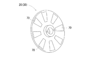
図1は、本実施例に係る積層型モーター10の基本構造を説明するための図である。図2は、本実施例に係る積層モーター10において永久磁石70を所定の間隔を置いて配置した中空円盤状の回転子30(または固定子20)を示した図である。図3は、本実施例に係る積層モーター10において巻線コイル60を所定の間隔を置いて配置した中空円盤状の回転子30(または固定子20)を示した図である。
FIG. 1 is a view for explaining the basic structure of a
図1に記載したように、本発明に係る積層型モーター10を端的に表現すれば、複数の中空円盤状の固定子20と複数の中空円盤状の回転子30を同芯円上に交互に積層することにより形成する積層型モーター10である(アウター回転仕様では、複数の中空円盤状の固定子(30)と複数の中空円盤状の回転子(20)を同芯円上に交互に積層することにより形成する積層型モーター10となる)。
As described in FIG. 1, when the
そして、図2に記載したように、其々の固定子20は周方向に沿って所定の間隔を置いて配置された複数の永久磁石70を備えており、図3に記載したように、其々の回転子30は、周方向に沿って所定の間隔を置いて配置された複数の巻線コイル60を備えている。尚、本発明に係る積層型モーター10の固定子20は、周方向に沿って所定の間隔を置いて配置された複数の巻線コイル60を備えた構成にしても良く、本発明に係る積層型モーター10の回転子30は、周方向に沿って所定の間隔を置いて配置された複数の永久磁石70を備えた構成にしても良い。
And, as shown in FIG. 2, each
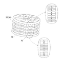
図4は、本発明に係る積層型モーター10における垂直方向に磁場の大きさの異なる永久磁石70を配置する構成について説明するための図である。要するに、本発明におけるさらなる特徴を説明するために、永久磁石70を周方向に配置した複数の固定子20(または回転子30)のみを抽出した図である。
FIG. 4 is a view for explaining a configuration in which
本発明は、固定子20と回転子30を垂直方向に交互に積層すること(永久磁石70のS極とN極が垂直方向に対面するように配置)により個々の永久磁石70から発生する磁力線を垂直方向において合成させることにより、全体として磁束密度を大きくするという特徴に加え、さらなる特徴として、磁場解析に基づいて垂直方向における磁束密度の異なる永久磁石70の配置等により磁力線分布を制御することで漏れ磁束が殆ど無い積層型モーター10、及び積層型発電機11を実現することができる。
According to the present invention, magnetic lines of force generated from the individual
上記の磁力線分布を制御することについて具体的に説明する。図4に記載したように、永久磁石70を周方向に配置した複数の固定子20(または回転子30)のみを抽出して見ると、本発明に係る積層型モーター10は、垂直方向において磁束密度の異なる永久磁石70を所定の間隔を置いて積層したものであることが分かる。図4の部分拡大図においては説明容易化のため、磁束密度の大小を永久磁石70の厚さで表現している。即ち、永久磁石70の厚さが厚いほど磁束密度が大きいことを表している。図4の右上の部分拡大図には磁束密度が、上から順に小、中、大、中、小、の順になるように配置しており、言い換えると、磁束密度が中心に向かって次第に大きくなり、積層の中心部において最大値をとるように配置している。一方、右下の部分拡大図には、磁束密度が上から順に大、小、小、小、大の順になるように配置しており、言い換えると、積層の両端部(上端部、下端部)の磁束密度を最大にして、それ以外の部分において磁束密度は小さくなるように永久磁石を配置している。
Control of the above-described magnetic force line distribution will be specifically described. As shown in FIG. 4, when only the plurality of stators 20 (or the rotors 30) in which the
上記に記載した永久磁石70の配置の根拠としては、磁場解析による解析結果を考慮しているのであるが、現状の磁場解析の結果においては、特に磁束漏れが少ないとされる永久磁石70の配置である。しかしながら、本発明の思想からすれば、上記のような永久磁石70の配置に限定されるのでは無く、さらに、より磁場漏れが少ない永久磁石70の配置が見つかれば、上記のような永久磁石70の配置に拘束されずに、これらを採用するべきであることは言うまでもない。
Although the analysis result by magnetic field analysis is taken into consideration as the basis of the arrangement of the
<積層型モーター、及び積層型発電機の実施形態>
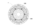
以下、本発明に係る積層型モーター10、及び積層型発電機11の一実施形態について、図5〜図6に基づいて詳細に説明する。図5は、本実施例に係るインナー回転仕様の積層型モーター10の断面図である。図6は、本実施例に係る積層型発電機11の全体上面図である。
<Embodiment of laminated motor and laminated generator>
Hereinafter, an embodiment of a
図5に記載したように、本実施例に係る積層型モーター10は、中心軸50に固定されて中心軸50の回転に連動して回転する回転子30と、中心軸50に固定されていない固定子20から構成されている。固定子20と回転子30の位置関係は、固定子20が回転子30と回転子30の間に、回転子30が、固定子20と固定子20の間にというように、其々が垂直方向において互い違いに、回転子30の回転が妨げられないように所定の間隔を開けて設置されている。ある回転子30と、その回転子30の上側(固定子20を挟んで)、又は下側(固定子20を挟んで)、或いは上下(固定子20を挟んで)に設置された回転子30は、スペーサーリング80を介して一体化されており、其々の回転子30がバラバラにならないようになっている。
As described in FIG. 5, the
図6は、本実施例に係る積層型発電機11の全体上面図である。本発明に係る積層型発電機11は、複数の中空円盤状の固定子20と複数の中空円盤状の回転子30を同芯円上に交互に積層することにより形成されている。図6に記載したように、複数の中空円盤状の固定子20と複数の中空円盤状の回転子30を同芯円上に交互に積層することにより、同時に形成される中心部筒状空間40に回転子30と接続した複数の羽根が設置されている。中心部筒状空間40に設置した複数の羽根に水等が流れることにより羽根を回転させ、羽根の回転と連動させて回転子30を回転させることにより、積層型の水力発電機として使用することができる。
<積層型モーター、及び積層型発電機の効果>
FIG. 6 is an overall top view of the stacked
<Effect of stacked motor and stacked generator>
本発明の特徴を端的に言えば、複数の中空円盤状の固定子20と、複数の中空円盤状の回転子30を、其々同芯円上に交互に積層することにより形成することにある。本発明に係る積層型モーター10、及び積層型発電機11は、中心軸50(中心部筒状空間40に設置した円柱構造物等)に固定されたインナー側が回転子30になるインナー回転仕様、アウター側が回転子30になるアウター回転仕様がある。其々の仕様においてさらに、回転子30に永久磁石70を配置し固定子20に巻線コイル60を配置する構成と、逆に、固定子20に永久磁石70を配置し回転子30に巻線コイル60を配置する構成があるので、組み合わせて4種類の仕様が考えられる。これらに加え、中心軸50とするか中心部筒状空間40にするかを選択できる。
Briefly speaking, the features of the present invention are formed by alternately laminating a plurality of hollow disk-shaped
本実施例においては、複数の固定子20が中心軸50(または中心部筒状空間40に設置した円柱構造物等)の外周に所定の間隔を置いて同心円上に固定され、周方向に沿って所定の間隔を置いて配置された複数の巻線コイル60を備えており、回転子30は固定20と固定子20の間に同心円上に設置されており、周方向に沿って所定の間隔を置いて配置された複数の永久磁石70を備えているので、固定子20と回転子30を垂直方向に交互に積層すること(S極とN極が垂直方向に交互に来るように配置)により個々の永久磁石70から出る磁力線を垂直方向に合成させることにより磁束密度を大きくし、従来のモーターよりも高出力を実現することができるようになったし、従来の発電機よりも発電効率を向上させることができるようになった。
In the present embodiment, a plurality of
また本発明によれば、垂直方向に磁場の大きさの異なる永久磁石70を配置(S極とN極が垂直方向に交互に来るように配置)する積層型モーター10、及び積層型発電機111であるので、磁束密度を大きくし、従来のモーターよりも高出力を実現することができると共に、磁場解析に基づいた垂直方向における永久磁石70の配置等により(垂直方向に磁場の大きさの異なる永久磁石を配置する)磁束密度分布を制御することで漏れ磁束が殆ど無い積層型モーター10、及び積層型発電機11を実現することができるようになった。
Further, according to the present invention, the
そして、固定子20(または回転子30)と固定子20(または回転子30)との間に生じる隙間の外端部にリング形状のスペーサーリング80を固定子20(または回転子30)と一体化させつつ介在させる積層型モーター10、及び積層型発電機11であるので、リング形状のスペーサーリング80の厚さをそれぞれの層によって変化させることで磁束密度分布を制御して、漏れ磁束が殆ど無い積層型モーター10、及び積層型発電機11を実現することができるようになった。
Then, a ring-shaped
さらに、アウター回転仕様の積層型モーター10、及び積層型発電機11において、ある回転子30と、その回転子30の上側(固定子20を挟んで)、又は下側(固定子20を挟んで)、或いは上下(固定子20を挟んで)に設置された回転子30は、スペーサーリング80を介して一体化されており、其々の回転子30がバラバラにならないようになっている。即ち、回転子30同士が、スペーサーリング80を介して固定されているので永久磁石70の垂直方向における配置がバラつくことが無い。即ち、垂直方向における位置関係のズレがないので、回転によっても磁束漏れが最小限に押さえられた永久磁石同士の垂直方向における配置が崩れることが無い。
Furthermore, in the
<積層型モーター、及び積層型発電機の変更例>
本発明に係る積層型モーター、及び積層型発電機は、上記した各実施形態の態様に何ら限定されるものではなく、固定子、回転子、中心部筒状空間、中心軸、巻線コイル、永久磁石、スペーサーリング等の構成を、本発明の趣旨を逸脱しない範囲で、必要に応じて適宜変更することができる。例えば、垂直方向における永久磁石の磁束密度を変化させることにより磁束密度分布を制御よる方式では無く、磁場解析を基に、垂直方向における巻線コイルの巻き数を変化させることにより磁束密度分布を制御して、漏れ磁束が殆ど無い積層型モーター、及び積層型発電機を実現しても良い。
<Modified example of laminated motor and laminated generator>
The laminated motor and the laminated generator according to the present invention are not limited to the aspect of each embodiment described above, and the stator, the rotor, the central cylindrical space, the central axis, the winding coil, The configurations of the permanent magnet, the spacer ring, and the like can be appropriately changed as needed without departing from the spirit of the present invention. For example, by changing the magnetic flux density of the permanent magnet in the vertical direction, not by controlling the magnetic flux density distribution, but controlling the magnetic flux density distribution by changing the number of turns of the winding coil in the vertical direction based on magnetic field analysis. Thus, it is possible to realize a laminated motor and a laminated generator having almost no leakage flux.
本発明に係る積層型モーター、及び積層型発電機は上記の如く優れた効果を奏するものであるので、従来のモーターよりも高出力を実現することができ、または従来の発電機よりも発電効率を向上させる、モーターの分野及び発電機の分野において、高出力かつ小型化モーター及び発電機として好適に用いることができる。 Since the laminated motor and the laminated generator according to the present invention exhibit the excellent effects as described above, they can achieve higher output than the conventional motor, or the power generation efficiency than the conventional generator. In the field of motors and in the field of generators, which can be used to improve power, it can be suitably used as a high output and miniaturized motor and generator.
10・・積層型モーター
11・・積層型発電機
20・・固定子
30・・回転子
40・・中心部筒状空間
50・・中心軸
60・・巻線コイル
70・・永久磁石
80・・スペーサーリング
10 · ·
Claims (7)
前記回転子は前記中心軸の外周に固定されて所定の間隔で同心円上に設置されており、
前記固定子は前記回転子と前記回転子の間に同心円上に設置されており、
前記固定子は周方向に沿って所定の間隔を置いて配置された複数の巻線コイルを備えており、
前記回転子は、周方向に沿って所定の間隔を置いて配置された複数の永久磁石を備えており、
前記複数の永久磁石は、垂直方向において磁束密度が中心に向かって次第に大きくなり、積層の中心部において最大値をとるように配置する、或いは、垂直方向において積層の両端部の磁束密度を最大にして、それ以外の部分において磁束密度は小さくなるように配置することを特徴とする積層型モーター。 A laminated motor comprising a stator, a rotor, and a central axis formed by alternately laminating a plurality of hollow disk stators and a plurality of hollow disk rotors on concentric circles,
The rotor is fixed to the outer periphery of the central axis and concentrically installed at a predetermined interval,
The stator is disposed concentrically between the rotor and the rotor ,
The stator comprises a plurality of winding coils arranged at predetermined intervals along the circumferential direction,
The rotor comprises a plurality of permanent magnets arranged at predetermined intervals along the circumferential direction,
The plurality of permanent magnets are arranged such that the magnetic flux density gradually increases toward the center in the vertical direction, and takes a maximum value at the center of the stack, or maximizes the magnetic flux density at both ends of the stack in the vertical direction. The stacked motor is characterized in that the magnetic flux density is reduced in the other part .
前記固定子は所定の間隔を置いて同心円上に設置されており、
前記回転子は前記固定子と前記固定子の間に同心円上に設置されており、
前記固定子は周方向に沿って所定の間隔を置いて配置された複数の巻線コイルを備えており、
前記回転子は、周方向に沿って所定の間隔を置いて配置された複数の永久磁石を備えており、
前記複数の永久磁石は、垂直方向において磁束密度が中心に向かって次第に大きくなり、積層の中心部において最大値をとるように配置する、或いは、垂直方向において積層の両端部の磁束密度を最大にして、それ以外の部分において磁束密度は小さくなるように配置することを特徴とする積層型モーター。 A laminated motor is formed by alternately laminating a plurality of hollow disk stators and a plurality of hollow disk rotors on concentric circles,
The stators are concentrically disposed at predetermined intervals,
The rotor is disposed concentrically between the stator and the stator ,
The stator comprises a plurality of winding coils arranged at predetermined intervals along the circumferential direction,
The rotor comprises a plurality of permanent magnets arranged at predetermined intervals along the circumferential direction,
The plurality of permanent magnets are arranged such that the magnetic flux density gradually increases toward the center in the vertical direction, and takes a maximum value at the center of the stack, or maximizes the magnetic flux density at both ends of the stack in the vertical direction. The stacked motor is characterized in that the magnetic flux density is reduced in the other part .
前記回転子は前記中心軸の外周に固定されて所定の間隔で同心円上に設置されており、
前記固定子は前記回転子と前記回転子の間に同心円上に設置されており、
前記固定子は周方向に沿って所定の間隔を置いて配置された複数の巻線コイルを備えており、
前記回転子は、周方向に沿って所定の間隔を置いて配置された複数の永久磁石を備えており、
前記複数の永久磁石は、垂直方向において磁束密度が中心に向かって次第に大きくなり、積層の中心部において最大値をとるように配置する、或いは、垂直方向において積層の両端部の磁束密度を最大にして、それ以外の部分において磁束密度は小さくなるように配置することを特徴とする積層型発電機。 A laminated generator comprising a stator, a rotor, and a central axis formed by alternately laminating a plurality of hollow disk stators and a plurality of hollow disk rotors on concentric circles,
The rotor is fixed to the outer periphery of the central axis and concentrically installed at a predetermined interval,
The stator is disposed concentrically between the rotor and the rotor ,
The stator comprises a plurality of winding coils arranged at predetermined intervals along the circumferential direction,
The rotor comprises a plurality of permanent magnets arranged at predetermined intervals along the circumferential direction,
The plurality of permanent magnets are arranged such that the magnetic flux density gradually increases toward the center in the vertical direction, and takes a maximum value at the center of the stack, or maximizes the magnetic flux density at both ends of the stack in the vertical direction. The stacked generator is characterized in that the magnetic flux density is reduced in the other parts .
前記固定子は所定の間隔を置いて同心円上に設置されており、
前記回転子は前記固定子と前記固定子の間に同心円上に設置されており、
前記固定子は周方向に沿って所定の間隔を置いて配置された複数の巻線コイルを備えており、
前記回転子は、周方向に沿って所定の間隔を置いて配置された複数の永久磁石を備えており、
前記複数の永久磁石は、垂直方向において磁束密度が中心に向かって次第に大きくなり、積層の中心部において最大値をとるように配置する、或いは、垂直方向において積層の両端部の磁束密度を最大にして、それ以外の部分において磁束密度は小さくなるように配置することを特徴とする積層型発電機。 A laminated generator formed by alternately laminating a plurality of hollow disk stators and a plurality of hollow disk rotors on concentric circles,
The stators are concentrically disposed at predetermined intervals,
The rotor is disposed concentrically between the stator and the stator ,
The stator comprises a plurality of winding coils arranged at predetermined intervals along the circumferential direction,
The rotor comprises a plurality of permanent magnets arranged at predetermined intervals along the circumferential direction,
The plurality of permanent magnets are arranged such that the magnetic flux density gradually increases toward the center in the vertical direction, and takes a maximum value at the center of the stack, or maximizes the magnetic flux density at both ends of the stack in the vertical direction. The stacked generator is characterized in that the magnetic flux density is reduced in the other parts .
Priority Applications (1)
| Application Number | Priority Date | Filing Date | Title |
|---|---|---|---|
| JP2016234887A JP6543239B2 (en) | 2016-12-02 | 2016-12-02 | Stacked motor and stacked generator |
Applications Claiming Priority (1)
| Application Number | Priority Date | Filing Date | Title |
|---|---|---|---|
| JP2016234887A JP6543239B2 (en) | 2016-12-02 | 2016-12-02 | Stacked motor and stacked generator |
Publications (2)
| Publication Number | Publication Date |
|---|---|
| JP2018093617A JP2018093617A (en) | 2018-06-14 |
| JP6543239B2 true JP6543239B2 (en) | 2019-07-10 |
Family
ID=62565727
Family Applications (1)
| Application Number | Title | Priority Date | Filing Date |
|---|---|---|---|
| JP2016234887A Active JP6543239B2 (en) | 2016-12-02 | 2016-12-02 | Stacked motor and stacked generator |
Country Status (1)
| Country | Link |
|---|---|
| JP (1) | JP6543239B2 (en) |
Families Citing this family (2)
| Publication number | Priority date | Publication date | Assignee | Title |
|---|---|---|---|---|
| CN112655142A (en) * | 2018-08-28 | 2021-04-13 | 波士顿科学国际有限公司 | Axial flux motor of percutaneous circulation supporting device |
| JP7426893B2 (en) | 2020-04-13 | 2024-02-02 | 三菱重工サーマルシステムズ株式会社 | Motor system and rotary compressor |
Family Cites Families (8)
| Publication number | Priority date | Publication date | Assignee | Title |
|---|---|---|---|---|
| JPH0645044Y2 (en) * | 1988-08-29 | 1994-11-16 | 株式会社コガネイ | Magnet type cylinder device |
| US5982074A (en) * | 1996-12-11 | 1999-11-09 | Advanced Technologies Int., Ltd. | Axial field motor/generator |
| JP2000333429A (en) * | 2000-01-01 | 2000-11-30 | Matsushita Seiko Co Ltd | Brushless electric motor and manufacturing method thereof |
| JP2003348805A (en) * | 2002-05-24 | 2003-12-05 | Nsk Ltd | Generator |
| JP4348982B2 (en) * | 2003-03-31 | 2009-10-21 | 株式会社富士通ゼネラル | Axial gap type induction motor |
| JP5037083B2 (en) * | 2006-10-06 | 2012-09-26 | 本田技研工業株式会社 | Electric motor |
| JP5052288B2 (en) * | 2007-06-28 | 2012-10-17 | 信越化学工業株式会社 | Axial gap type rotating machine |
| JP5181827B2 (en) * | 2008-05-20 | 2013-04-10 | 日立金属株式会社 | Axial gap motor and fan device using the same |
-
2016
- 2016-12-02 JP JP2016234887A patent/JP6543239B2/en active Active
Also Published As
| Publication number | Publication date |
|---|---|
| JP2018093617A (en) | 2018-06-14 |
Similar Documents
| Publication | Publication Date | Title |
|---|---|---|
| JP5491484B2 (en) | Switched reluctance motor | |
| JP4499764B2 (en) | Electric motor | |
| US7569962B2 (en) | Multi-phase brushless motor with reduced number of stator poles | |
| JP2019024296A (en) | Rotary electric machine | |
| US20210234415A1 (en) | Rotating electric machine | |
| JP2009072010A (en) | Axial gap type coreless rotating machine | |
| JP5695748B2 (en) | Rotating electric machine | |
| JP6048191B2 (en) | Multi-gap rotating electric machine | |
| CN110268610B (en) | Synchronous machine with magnetic rotating field reduction and flux concentration | |
| US20170040855A1 (en) | Rotor for a rotary electric machine | |
| US7638917B2 (en) | Electrical rotating machine | |
| JP2007274869A (en) | Slot-less permanent magnet type rotary electric machine | |
| JP2016538817A (en) | Transverse flux type electric machine | |
| JP2010284035A (en) | Permanent magnet rotating electrical machine | |
| JP6543239B2 (en) | Stacked motor and stacked generator | |
| JP2008252979A (en) | Axial-gap type rotating machine | |
| JP6057204B2 (en) | Superconducting magnetic pole | |
| JP5698715B2 (en) | Axial gap type brushless motor | |
| WO2016190033A1 (en) | Rotary electric device stator | |
| JP2014192951A (en) | Dynamo-electric machine, electric motor unit and generator unit | |
| JP2009027849A (en) | Permanent magnet type rotary electric machine | |
| JP2016129447A (en) | Rotary electric machine | |
| JP5403003B2 (en) | Coreless brushless motor | |
| JP2013132149A (en) | Rotary electric machine | |
| JP5884464B2 (en) | Rotating electric machine |
Legal Events
| Date | Code | Title | Description |
|---|---|---|---|
| A621 | Written request for application examination |
Free format text: JAPANESE INTERMEDIATE CODE: A621 Effective date: 20180327 |
|
| A131 | Notification of reasons for refusal |
Free format text: JAPANESE INTERMEDIATE CODE: A131 Effective date: 20181029 |
|
| A977 | Report on retrieval |
Free format text: JAPANESE INTERMEDIATE CODE: A971007 Effective date: 20181031 |
|
| A521 | Request for written amendment filed |
Free format text: JAPANESE INTERMEDIATE CODE: A523 Effective date: 20181228 |
|
| TRDD | Decision of grant or rejection written | ||
| A01 | Written decision to grant a patent or to grant a registration (utility model) |
Free format text: JAPANESE INTERMEDIATE CODE: A01 Effective date: 20190603 |
|
| A61 | First payment of annual fees (during grant procedure) |
Free format text: JAPANESE INTERMEDIATE CODE: A61 Effective date: 20190614 |
|
| R150 | Certificate of patent or registration of utility model |
Ref document number: 6543239 Country of ref document: JP Free format text: JAPANESE INTERMEDIATE CODE: R150 |
|
| R250 | Receipt of annual fees |
Free format text: JAPANESE INTERMEDIATE CODE: R250 |