JP5395358B2 - A gas-liquid separator and a refrigeration apparatus including the gas-liquid separator. - Google Patents
A gas-liquid separator and a refrigeration apparatus including the gas-liquid separator. Download PDFInfo
- Publication number
- JP5395358B2 JP5395358B2 JP2008038034A JP2008038034A JP5395358B2 JP 5395358 B2 JP5395358 B2 JP 5395358B2 JP 2008038034 A JP2008038034 A JP 2008038034A JP 2008038034 A JP2008038034 A JP 2008038034A JP 5395358 B2 JP5395358 B2 JP 5395358B2
- Authority
- JP
- Japan
- Prior art keywords
- gas
- liquid
- phase
- liquid separation
- outlet pipe
- Prior art date
- Legal status (The legal status is an assumption and is not a legal conclusion. Google has not performed a legal analysis and makes no representation as to the accuracy of the status listed.)
- Active
Links
Images


Classifications
-
- F—MECHANICAL ENGINEERING; LIGHTING; HEATING; WEAPONS; BLASTING
- F25—REFRIGERATION OR COOLING; COMBINED HEATING AND REFRIGERATION SYSTEMS; HEAT PUMP SYSTEMS; MANUFACTURE OR STORAGE OF ICE; LIQUEFACTION SOLIDIFICATION OF GASES
- F25B—REFRIGERATION MACHINES, PLANTS OR SYSTEMS; COMBINED HEATING AND REFRIGERATION SYSTEMS; HEAT PUMP SYSTEMS
- F25B43/00—Arrangements for separating or purifying gases or liquids; Arrangements for vaporising the residuum of liquid refrigerant, e.g. by heat
- F25B43/02—Arrangements for separating or purifying gases or liquids; Arrangements for vaporising the residuum of liquid refrigerant, e.g. by heat for separating lubricants from the refrigerant
-
- F—MECHANICAL ENGINEERING; LIGHTING; HEATING; WEAPONS; BLASTING
- F25—REFRIGERATION OR COOLING; COMBINED HEATING AND REFRIGERATION SYSTEMS; HEAT PUMP SYSTEMS; MANUFACTURE OR STORAGE OF ICE; LIQUEFACTION SOLIDIFICATION OF GASES
- F25B—REFRIGERATION MACHINES, PLANTS OR SYSTEMS; COMBINED HEATING AND REFRIGERATION SYSTEMS; HEAT PUMP SYSTEMS
- F25B2400/00—General features or devices for refrigeration machines, plants or systems, combined heating and refrigeration systems or heat-pump systems, i.e. not limited to a particular subgroup of F25B
- F25B2400/23—Separators
-
- F—MECHANICAL ENGINEERING; LIGHTING; HEATING; WEAPONS; BLASTING
- F25—REFRIGERATION OR COOLING; COMBINED HEATING AND REFRIGERATION SYSTEMS; HEAT PUMP SYSTEMS; MANUFACTURE OR STORAGE OF ICE; LIQUEFACTION SOLIDIFICATION OF GASES
- F25B—REFRIGERATION MACHINES, PLANTS OR SYSTEMS; COMBINED HEATING AND REFRIGERATION SYSTEMS; HEAT PUMP SYSTEMS
- F25B2500/00—Problems to be solved
- F25B2500/17—Size reduction
Description
本発明は、例えば冷凍サイクルや蒸気サイクル等の熱機関の気液分離装置およびオイルセパレータに関し、詳細には、より一層の高性能化並びに小形化を図る技術に関する。 The present invention relates to a gas-liquid separator and an oil separator for a heat engine such as a refrigeration cycle or a steam cycle, and more particularly to a technique for further improving performance and downsizing.
例えば、冷凍サイクルで使用される気液分離装置およびオイルセパレータとしては、重力によって液あるいは油を溜めるタンクを用いたり、旋回流の遠心力によって液あるいは油を外壁に付着させ、重力によって液あるいは油を回収する気液分離装置等が用いられている。 For example, as a gas-liquid separator and oil separator used in a refrigeration cycle, a tank that stores liquid or oil by gravity is used, or liquid or oil is attached to an outer wall by centrifugal force of swirling flow, and liquid or oil is collected by gravity. A gas-liquid separation device or the like that collects water is used.
かかる構成の気液分離装置およびオイルセパレータでは、基本的に重力や遠心力などの体積力によって密度の大きい液相を分離する構造となっている。このため、タンクや旋回流発生装置を用いるため大型の装置となっている上、気液分離装置の設置位置や向きに自由度が少ない。更には気液を効率良く分離する手段が示されていないものであった。 The gas-liquid separator and the oil separator having such a configuration basically have a structure in which a liquid phase having a high density is separated by a body force such as gravity or centrifugal force. For this reason, since it uses a tank and a swirl flow generator, it is a large-sized device, and there are few degrees of freedom in the installation position and direction of a gas-liquid separation device. Furthermore, no means for efficiently separating the gas and liquid has been shown.
そこで、先に、発明者らは前記した課題を解決すべく、溝内で表面張力の作用により液相を溝に付着させて流すことで、気液分離装置をより高性能化並びに小形化することを目的とする発明の特許を出願した。
従来の気液分離装置およびオイルセパレータでは、密度の大きな液相(油)を重力や遠心力などの体積力で分離する構造となっているため、体積力が支配的となるように曲率半径や流速を設定する必要があり、また設置方向と重力方向とをマッチングさせる必要があるなどの工夫が必要であった。 Conventional gas-liquid separators and oil separators have a structure in which a liquid phase (oil) with a high density is separated by a bulk force such as gravity or centrifugal force. It is necessary to set the flow velocity and to devise such as matching the installation direction and the gravity direction.
これらは、重力方向に高さを確保したタンクが必要である、あるいは遠心力を用いる場合は流速を高める必要がある。また、曲がり流れを発生させるために、仕切り板等によって流れの向きを変える必要がある。このため、圧力損失が大きくなりやすく、それを防ぐために装置が大型なものとなり、小型化が困難であった。 These require a tank that has a height in the direction of gravity, or need to increase the flow rate when centrifugal force is used. Further, in order to generate a bending flow, it is necessary to change the direction of the flow using a partition plate or the like. For this reason, pressure loss tends to increase, and the apparatus becomes large in order to prevent it, and it is difficult to reduce the size.
上記した気液分離装置を小型化しようとする場合には、流速を大きく、曲率半径を小さくする必要があるが、小型化するに伴って遠心力や重力等の体積力に対して粘性力や表面張力等の影響が無視できなくなるため、装置自体の特性が低下してしまったり、あるいは圧力損失が大きくなるため、冷凍サイクル性能が低下してしまうという問題があった。 In order to reduce the size of the gas-liquid separation device described above, it is necessary to increase the flow velocity and reduce the radius of curvature. Since the influence of the surface tension or the like cannot be ignored, there is a problem that the characteristics of the apparatus itself deteriorates or the pressure loss increases, and the refrigeration cycle performance deteriorates.
本発明は、先に出願したPCT/JP2006/322682を更に発展させ、表面張力効果を用いることで気液分離装置をより高性能化並びに小形化することを目的とする気液分離装置およびオイルセパレータにあって、気相に乗って運ばれる液滴を極力捕捉でき、高性能で小形の気液分離装置およびオイルセパレータを提供し、さらに、その気液分離装置を空気調和機、冷蔵庫、冷凍庫、除湿機、ショーケース、自動販売機およびカーエアコン等の冷凍装置等への採用を提案するものである。 The present invention further develops the previously filed PCT / JP2006 / 322682 and uses the surface tension effect to improve the performance and miniaturization of the gas-liquid separator, and an oil separator. Therefore, it is possible to capture droplets carried in the gas phase as much as possible, and to provide a high-performance and small gas-liquid separator and oil separator, and further, the gas-liquid separator is an air conditioner, refrigerator, freezer, It is proposed to be used in refrigeration equipment such as dehumidifiers, showcases, vending machines and car air conditioners.
気相に乗って運ばれる液滴を極力捕捉する考え方は二つあり、その第一は溝内で液滴を極力捕捉する手段であり、第二は万一液滴が気相に乗って溝から出ても、気相出口管から流出し難い構成にする手段である。以下にそれらの手段について説明する。 There are two ways to capture the droplets carried in the gas phase as much as possible, the first of which is to capture the droplets in the groove as much as possible, and the second is that the droplets should get on the gas phase and get into the groove It is a means to make it the structure which is hard to flow out of a gaseous-phase exit pipe | tube, even if it comes out of. These means will be described below.
請求項1に記載の発明は、気液分離室の一部に液相出口管に向かう溝を持つ溝付き体を設け、その気液分離室の上流に外郭体と入口仕切り体をもって狭小空間を作ると共に、入口管より導かれた気液二相流を該狭小空間を通した後で溝付き体から気液分離室に導き、上記気液二相流を、液相は溝付き体を通して液相出口管に導くようにし、気相は気液分離室から気相出口管に導くようにした気液分離機構を持つことを特徴とする気液分離装置において、溝を外郭体の内表面から外郭体の中心線に向かう線に対して角度α傾けると共に、溝付き体の表面を流れ方向に対して角度θ傾斜した略波形状とし、かつ、その流れ方向に対して角度θ傾斜した略波形状を流れ方向に対して半径方向外側に広がるように形成したことを特徴とする気液分離装置である。 According to the first aspect of the present invention, a grooved body having a groove toward the liquid phase outlet pipe is provided in a part of the gas-liquid separation chamber, and a narrow space is formed with an outer body and an inlet partition upstream of the gas-liquid separation chamber. The gas-liquid two-phase flow guided from the inlet pipe is guided to the gas-liquid separation chamber from the grooved body after passing through the narrow space, and the gas-liquid two-phase flow is passed through the grooved body. In the gas-liquid separation device characterized in that the gas phase has a gas-liquid separation mechanism that is led to the phase outlet pipe and the gas phase is led from the gas-liquid separation chamber to the gas phase outlet pipe, the groove is formed from the inner surface of the outer body. Inclined by an angle α with respect to the line toward the center line of the outer body, the surface of the grooved body has a substantially wave shape inclined at an angle θ with respect to the flow direction, and a substantially wave inclined at an angle θ with respect to the flow direction. A gas-liquid separation device characterized in that the shape is formed to spread outward in the radial direction with respect to the flow direction. A.
請求項2に記載の発明は、請求項1に記載の気液分離装置であって、前記狭小空間を通り溝付き体に導かれた気液二相流において、液相は、溝付き体を流下し液相出口管に向かうようにし、少なくとも一部の気相は、出口仕切り体に設けた連通穴を介さずに気液分離室に導かれた後、気液分離室上部に設けた気相出口管に向かうようにしたことを特徴とする。
Invention of
請求項3に記載の発明は、請求項1に記載の気液分離装置であって、入口仕切り体、外郭体、出口仕切り体及び仕切り円筒からなる群より選択される一以上の部材で溝付き体の位置を規定したことを特徴とする。
The invention according to
請求項4に記載の発明は、請求項1に記載の気液分離装置であって、気相出口管を気液分離装置の上部に設け、気相出口管の下部は入口仕切り体の上部に流体導通可能な状態で接続すると共に、気相出口管の下端部が狭小空間より下に突き出ないようにしたことを特徴とする。
Invention of
請求項5に記載の発明は、請求項1〜4のいずれか一項記載の気液分離装置であって、外郭体と入口仕切り体により流入室と気液分離室とを仕切ると共に、該流入室を該気液分離室よりも上部に位置させた気液分離装置であり、入口管より導かれた気液二相流を外郭体の横から該流入室に流入させることで該気液二相流を該流入室内で旋回させ、かつ、気相出口管を該気液分離装置の上部に設けることで、気相が入口管を通り越して該気液分離装置の上部へ導かれるようにしたことを特徴とする。
The invention according to
請求項6に記載の発明は、請求項1から請求項5のいずれか一項記載の気液分離装置を空気調和器等の冷凍サイクル中に組み込んだことを特徴とする気液分離装置を備えた冷凍装置である。 A sixth aspect of the present invention includes a gas-liquid separation device in which the gas-liquid separation device according to any one of the first to fifth aspects is incorporated in a refrigeration cycle such as an air conditioner. Refrigeration equipment.
請求項7に記載の発明は、請求項1から請求項5のいずれか一項記載の気液分離装置の二相流入口管に、冷凍サイクル中の減圧器の出口管を接続し、気液分離装置の液相出口管を蒸発器に至る管路に接続し、一方、気液分離装置の気相出口管をバイパス路および抵抗調整体を介して圧縮機の吸込み管に接続したことを特徴とする冷凍装置である。 According to a seventh aspect of the present invention, an outlet pipe of a decompressor in a refrigeration cycle is connected to the two-phase inlet pipe of the gas-liquid separator according to any one of the first to fifth aspects, and the gas-liquid The liquid-phase outlet pipe of the separator is connected to a pipe line leading to the evaporator, while the gas-phase outlet pipe of the gas-liquid separator is connected to the suction pipe of the compressor through a bypass path and a resistance adjuster. This is a refrigeration apparatus.
請求項8に記載の発明は、請求項1から請求項5のいずれか一項記載の気液分離装置の二相流入口管に、冷凍サイクル中の圧縮機吐出管を接続し、気液分離装置の液相出口管を流量調整絞りを介して圧縮機吸込み管に接続し、一方、気液分離装置の気相出口管を冷凍サイクルの凝縮器に至る管路に接続したことを特徴とする冷凍装置である。 According to an eighth aspect of the present invention, a compressor discharge pipe in the refrigeration cycle is connected to the two-phase inlet pipe of the gas-liquid separation apparatus according to any one of the first to fifth aspects, and the gas-liquid separation is performed. The liquid-phase outlet pipe of the apparatus is connected to the compressor suction pipe via a flow rate adjusting throttle, while the gas-phase outlet pipe of the gas-liquid separator is connected to a pipe line leading to the condenser of the refrigeration cycle. Refrigeration equipment.
本発明によれば、溝付き体の表面にある傾斜角をもった略波形状を設けたことで、溝付き体に挟まれた空間内に強い二次流れを発生することができる。また、この二次流れは溝付き体に挟まれた非常に狭い空間内の流れとなるため、その流線の曲率半径を非常に小さいものとすることができる。このことで、液滴に非常に強い遠心力を働かせることができる。また、気液分離装置の体積あたりの溝付き体の表面積をコンパクトに実装することで、体積あたりの液滴捕獲面積を増すことができるので、非常にコンパクトな気液分離装置を構成することができる。 According to the present invention, a strong secondary flow can be generated in the space sandwiched between the grooved bodies by providing a substantially wave shape having an inclination angle on the surface of the grooved body. Further, since this secondary flow becomes a flow in a very narrow space sandwiched between the grooved bodies, the radius of curvature of the streamline can be made very small. This makes it possible to apply a very strong centrifugal force to the droplet. In addition, since the surface area of the grooved body per volume of the gas-liquid separator can be compactly mounted, the droplet capture area per volume can be increased, so that a very compact gas-liquid separator can be configured. it can.
また、本発明によれば、溝付き体の表面に設けられた流れ方向に傾斜した略波形状を、流れの向きに半径方向外側に広がるように形成したことで、強い二次流れを発生させて、その遠心力の効果によって捕捉した液滴を再び液滴として飛散させることなく、流れのせん断力と重力を利用して壁面を伝って有効に流下させることができる。 Further, according to the present invention , a strong secondary flow is generated by forming the substantially wave shape inclined in the flow direction provided on the surface of the grooved body so as to spread radially outward in the flow direction. Thus, the droplets captured by the centrifugal force can be effectively flowed down along the wall surface using the shearing force and gravity of the flow without scattering again as droplets.
更に、本発明によれば、溝を外郭体の中心線に対して角度α傾けて設けることにより、以下の三つの効果が得られる。第一の効果は、溝を傾けることにより溝幅b’は傾けない場合の溝幅bよりも小さくなる。溝内を気相が流れるとき、気相に乗って運ばれる液滴は溝幅が小さいほど溝の表面に衝突し液膜になりやすいため、溝を傾け、実質的な溝幅を小さくすることにより、気液分離性能を向上することができる。第二の効果は、溝を角度α傾けることにより、溝から出る気相の流れ方向は気液分離室に角度αを持ち流入する。したがって、気液分離室に開口する全ての溝から角度αを持ち気相が気液分離室に流入することにより、気液分離室内に旋回流が発生する。気相に乗り溝から流出した微細液滴は旋回流による遠心力の作用により、溝の開口部に近い気液分離室内の空間に集まり易くなり、微細液滴同士が結合しあい、より大きな液滴になる確率が増加する。液滴径dが大きくなると液滴は下方に落下し易くなる。したがって、液滴は気相出口管6から流出され難くなり、高性能な気液分離装置を提供できる。第三の効果は、溝の実質的長さhが一定の状態で溝を傾けることにより、溝底面に対する垂直方向溝深さh’は傾けない場合の溝深さhよりも小さくなる。したがって、溝を傾けることにより溝頂点仮想円の径Dtは実質的に大きくなる。そのため、気液分離室内軸方向気相上昇速度uaは低下し、液滴は下方に落下し易くなる。したがって、液滴は気相出口管から流出され難くなり、高性能な気液分離装置を提供できる。
Furthermore, according to the present invention , the following three effects can be obtained by providing the groove at an angle α with respect to the center line of the outer body. The first effect is that the groove width b ′ becomes smaller than the groove width b when the groove is not inclined by inclining the groove. When the gas phase flows in the groove, the droplets carried on the gas phase tend to collide with the surface of the groove and become a liquid film as the groove width decreases, so tilt the groove to make the actual groove width smaller. As a result, gas-liquid separation performance can be improved. The second effect is that the groove is inclined at an angle α, so that the flow direction of the gas phase coming out of the groove flows into the gas-liquid separation chamber with an angle α. Therefore, a swirling flow is generated in the gas-liquid separation chamber by having the angle α from all the grooves opened in the gas-liquid separation chamber and flowing into the gas-liquid separation chamber. Fine droplets that flow out of the groove on the gas phase easily gather in the space inside the gas-liquid separation chamber near the opening of the groove due to the centrifugal force due to the swirling flow. The probability of becoming increased. As the droplet diameter d increases, the droplets easily fall downward. Therefore, it is difficult for the droplets to flow out from the gas
以下、本発明を適用した具体的な実施の形態について図面を参照しながら詳細に説明する。 Hereinafter, specific embodiments to which the present invention is applied will be described in detail with reference to the drawings.
「第1の実施の形態」
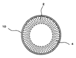
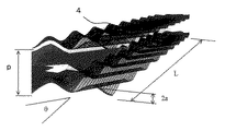
図1は第1の実施の形態の気液分離装置を示す断面図である。図2は図1に示す気液分離装置のA−A断面図である。図3は薄板を折り曲げて構成した溝付き体4の展開斜視図であり、また図4は図3の溝付き体4の1ピッチを取り出したときの拡大図である。図1に示すように外郭体10内に液相出口管7に向かう溝2を有する溝付き体4が設けられており、溝付き体4の上流には入り口仕切り体16が設けられ、気液分離室1を構成している。溝付き体4は図3に示すように薄板を折り曲げ溝2を構成し、これをまるめて図2に示すように外郭体10内に挿入している。溝付き体4の下流には気相出口管6に接合された出口仕切り体8により溝付き体4の高さ方向の下部位置を規定するように、気相出口管6が外郭体10の下縮管部13に接合されている。
気液二相流は入口管5から流入し、さらに入り口仕切り体16と外郭体B11をもって作られる狭小空間12に流入する。入り口仕切り体16をもって作られる狭小空間12で気液二相流を溝2に沿って供給するので、気液二相流は溝に沿って溝に流入する。溝付き体4の内部に流入した二相流の液相は基本的には溝2の表面に付着し液膜となる。また、気相に乗って運ばれる液滴は溝2の表面に衝突し液膜となる。液膜は下方に流下し、液相出口管7から流出する。液滴を除去された気相は気相出口管6から流出する。“First Embodiment”
FIG. 1 is a cross-sectional view showing a gas-liquid separator according to a first embodiment. 2 is a cross-sectional view of the gas-liquid separator shown in FIG. FIG. 3 is a developed perspective view of the
The gas-liquid two-phase flow flows from the
ここで、溝付き体4の表面には図4に示すような主流方向に傾斜した略波形状が設けられている。この略波形状は、流れの向きに半径方向外側に広がるように形成されている。この傾斜した略波形状の効果により、溝2の内部には図10に示したような断面内の2次流れ20が発生する。その間を気相に搬送された液滴14が流れると、この液滴は2次流れ20によって断面内を回転運動し、その際に働く遠心力の効果によって溝付き体4に衝突する。衝突した液滴14は溝付き体の表面で液膜となり、主流のせん断力と重力によって略波形状に沿って下方に流下する。このようにして、気相内の液滴を気液分離することができる。 Here, the surface of the
なお、発生する二次流れは溝付き体の溝内の非常に狭い空間内の流れとなるため、その流線の曲率半径も非常に小さいものとなる。このことで、液滴に非常に強い遠心力を働かせることができる。また、気液分離装置の体積あたりの溝付き体の表面積をコンパクトに実装することができるので、体積あたりの液滴捕獲面積を増すことができ、非常にコンパクトな気液分離装置を構成することができる。 In addition, since the secondary flow to generate | occur | produces becomes a flow in the very narrow space in the groove | channel of a grooved body, the curvature radius of the streamline also becomes a very small thing. This makes it possible to apply a very strong centrifugal force to the droplet. In addition, since the surface area of the grooved body per volume of the gas-liquid separator can be mounted in a compact manner, the droplet capture area per volume can be increased, and a very compact gas-liquid separator can be constructed. Can do.
「第2の実施の形態」
図5は第2の実施の形態の気液分離装置を示す断面図である。図6は薄板を折り曲げて構成した溝付き体4の展開斜視図であり、また図7は図3の溝付き体4の1ピッチを取り出したときの拡大図である。この略波形状は、流れの向きに末広がりに形成されている。“Second Embodiment”
FIG. 5 is a cross-sectional view showing a gas-liquid separator according to the second embodiment. FIG. 6 is a developed perspective view of the
ここで、溝付き体4の溝の表面には図7に示すような主流方向に傾斜した略波形状が設けられている。この略波形状は、流れの向きに末広がりに形成されている。この傾斜した略波形状の効果により、溝2の内部には図10に示したような断面内の2次流れ20が発生する。その間を気相に搬送された液滴14が流れると、この液滴は2次流れ20によって断面内を回転運動し、その際に働く遠心力の効果によって溝付き体4に衝突する。衝突した液滴14は溝付き体の表面で液膜となり、主流のせん断力と重力によって略波形状に沿って下方に流下する。このようにして、気相内の液滴を気液分離することができる。 Here, the surface of the groove of the
「第3の実施の形態」
図8は第3の実施の形態の気液分離装置を示す断面図である。第3の実施例では、図9に示すように、溝付き体4と気液分離室1の間に、仕切り円筒37が設置されている。仕切り円筒37により、溝付き体4の中を流れる気液二相流は、気液分離室1に逃げることなく、溝付き体4の下方に至るまで流れることができる。このことで、液滴が溝付き体の壁面に衝突するために必要な距離を十分に確保することができる。溝付き体4の下方に至った気相は出口仕切り体8に設けられた連通穴22から気液分離室1内に流入し気相出口管6から流出する。“Third Embodiment”
FIG. 8 is a cross-sectional view showing a gas-liquid separator according to the third embodiment. In the third embodiment, as shown in FIG. 9, a
以下、液滴が壁面に衝突するまでの現象について考察する。第一次近似として、図11に示すようなモデルを考える。半径r0の位置で回転運動する直径dの液滴14に働く遠心力と、液滴に働く気相からの半径方向抗力のバランスを考える。液滴の半径方向速度をur、周方向速度をulとすると、遠心力と抗力のバランスは次式で表される。

![]()
主流速度u×飛行時間Tが、液滴が壁面に衝突するまでに必要な液滴の流れ方向飛行距離であり、これが気液分離装置の溝付き体の必要な長さLとなる。Hereinafter, the phenomenon until the droplet collides with the wall surface will be considered. As a first approximation, consider a model as shown in FIG. Consider the balance between the centrifugal force acting on the
![]()
The main flow velocity u × flight time T is the flight distance flight distance necessary for the droplet to collide with the wall surface, and this is the required length L of the grooved body of the gas-liquid separator.
このモデルを図10の溝付き体に応用してみる。二次流れとして、溝ピッチ間に1対の渦対が形成されるものとし、渦の半径r0を溝付き体ピッチpのa倍、
r0=a×p (7)
と仮定する。また、渦の流線と溝付き体壁面までの距離をhとし、これが上述の渦の半径r0と溝付き体ピッチpを用いて以下のように記述できると仮定する。
![]()
また、渦の半径方向速度ulは、主流速度uのb倍と仮定する。すなわち、
ul=b×u (9)
式(7)〜(9)を式(6)に代入すると、液滴が壁面に衝突するまでの飛行時間Tが得られ、これに主流速度uを乗じることで、液滴の飛行距離、すなわち液滴を捕獲するために必要な溝付き体の長さLが以下のように求められる。
r 0 = a × p (7)
Assume that Further, assume that the distance to streamline the grooved body wall of the vortex and is h, it can be described as follows using a radius r 0 and the grooved body pitch p of the vortex mentioned above.
![]()
Further, it is assumed that the radial velocity u l of the vortex is b times the main flow velocity u. That is,
u 1 = b × u (9)
By substituting Equations (7) to (9) into Equation (6), the flight time T until the droplet collides with the wall surface is obtained, and by multiplying this by the mainstream velocity u, the flight distance of the droplet, that is, The length L of the grooved body necessary for capturing the droplet is obtained as follows.
「第4の実施の形態」
図13は第4の実施の形態の気液分離装置を示す断面図である。図14は図13に示す気液分離装置のA−A断面図である。図15は薄板を折り曲げて構成した溝付き体4の展開斜視図である。図16は溝2を傾けて設けた効果を示す原理モデル図である。図13に示すように外郭体10内に液相出口管7に向かう溝2を有する溝付き体4が設けられており、溝付き体4の上流には、入り口仕切り体16が設けられ、気液分離室1を構成している。溝付き体4は図15に示すように薄板を折り曲げ溝2を構成し、これをまるめて図14に示すように外郭体10内に挿入している。溝付き体4の下流には気相出口管6に接合された出口仕切り体8により溝付き体4の高さ方向の下部位置を規定するように、気相出口管6が外郭体10の下縮管部13に接合されている。
気液二相流は入口管5から流入し、さらに入り口仕切り体16と外郭体B11をもって作られる狭小空間12に流入する。狭小空間12で気液二相流を溝2に沿って供給するので、気液二相流は溝に沿って溝に流入する。溝付き体4の内部に流入した二相流の液相は基本的には溝2の表面に付着し、液膜となる。また気相に乗って運ばれる液滴は溝2の表面に衝突し液膜となる。液膜は下方に流下し、液相出口管7から流出する。液滴を除去された気相は気相出口管6から流出する。“Fourth Embodiment”
FIG. 13 is a cross-sectional view showing a gas-liquid separator according to a fourth embodiment. FIG. 14 is a cross-sectional view of the gas-liquid separator shown in FIG. FIG. 15 is a developed perspective view of the
The gas-liquid two-phase flow flows from the
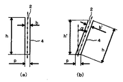
ここで、溝付き体4の溝2は図14に示すように外郭体10の中心線15に対して角度α傾けて設けられている。溝を角度α傾けることによる効果を図16に示した原理モデル図を用いて説明する。図16は溝付き体4の一つの溝を取り出した原理モデル図であり、図16(a)は溝を傾けない場合のモデル図であり、図16(b)は溝を角度α傾けた場合のモデル図である。 Here, the
溝を傾けることによる第一の効果を説明する。溝を傾けることにより、溝幅b’は傾けない場合の溝幅bよりも小さくなる。溝内を気相が流れるとき、気相に乗って運ばれる液滴は溝幅が小さいほど溝2の表面に衝突し液膜になりやすいため、溝を傾け、実質的な溝幅を小さくすることにより、気液分離性能を向上することが出来る。なお、図16(a)において、単に溝ピッチpを小さくすることも考えられるが、外郭体10の径が一定の状態で単に溝ピッチpを小さくすると溝数が増えることを意味し、溝付き体を構成する素材の使用量が増加し、気液分離装置の価格が高くなる問題がある。したがって、溝を傾けることにより実質的な溝幅を小さくでき、高性能で、安価な気液分離装置を提供できる。 The first effect by tilting the groove will be described. By tilting the groove, the groove width b 'becomes smaller than the groove width b when not tilting. When the gas phase flows in the groove, the droplet carried on the gas phase is likely to collide with the surface of the
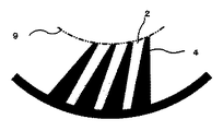
溝を傾けることによる第二の効果を図14を用いて説明する。図14に示すように溝を角度α傾けることにより、溝から出る気相の流れ方向23は気液分離室1に角度αを持ち流入する。したがって、気液分離室1に開口する全ての溝から角度αを持ち気相が流入することにより、気液分離室1内に旋回流24が発生する。 A second effect by tilting the groove will be described with reference to FIG. As shown in FIG. 14, when the groove is inclined at an angle α, the
溝2内を気相に乗って運ばれる液滴が極めて小さい場合、微細液滴は溝表面に衝突せずに、溝2から気液分離室1に流出する場合がある。このとき、図20に示すように、溝が傾いていない場合には、気液分離室1に流出した微細液滴は気液分離室1の中心に向かい、一様に分布し、気液分離室内軸方向気相上昇速度ua25に乗り気相出口管6から流出する。それに対して、溝を傾けることにより気液分離室1内に旋回流24が発生し、微細液滴は旋回流による遠心力の作用により、溝2の開口部に近い気液分離室内の空間に集まり易くなり、微細液滴同士が結合しあい、より大きな液滴になる確率が増加する。液滴が大きくなると、液滴に作用する重力Fgが、軸方向気相上昇速度ua25による液的を上昇させる抗力FDを上回るため、液滴は下方に落下し易くなり、気相出口管6から流出され難くなる。すなわち、
![]()
![]()
![]()
![]()
溝を傾けることによる第三の効果を図13、図14および図16を用いて説明する。
図16に示すように、溝の実質的長さhが一定の状態で溝を傾けることにより、溝底面に対する垂直方向溝深さh’は傾けない場合の溝深さhよりも小さくなる。したがって、溝を傾けることにより図14に示す溝頂点仮想円9の径Dtは実質的に大きくなる。そのため、気液分離室内軸方向気相上昇速度ua25は低下し、式(16)に示されるように、FD<Fgの傾向が強くなり、液滴は下方に落下し易くなる。したがって、溝を傾けることにより、液滴は気相出口管6から流出され難くなり、高性能な気液分離装置を提供できる。なお、以上に述べた第4の実施形態では薄板を折り曲げた溝付き体4を使用した例を述べたが、溝付き体は図17に示すように機械加工等の何らかの手段で製作した他の溝付き体でも以上に述べた効果は同じであることは言うまでも無い。A third effect by inclining the groove will be described with reference to FIGS. 13, 14, and 16.
As shown in FIG. 16, when the groove is tilted with the substantial length h of the groove being constant, the vertical groove depth h ′ with respect to the groove bottom surface becomes smaller than the groove depth h when not tilting. Therefore, by inclining the groove, the diameter Dt of the groove apex
「第5の実施の形態」
図18は第5の実施の形態の気液分離装置を示す断面図である。図19は図18のC−C断面図である。図20は図18のA−A断面図である。図19に示すように、入口管5は外郭体B11の横から流入室19に接線方向に流入するように設けられている。図18に示すように、気液分離装置は気相出口管6を気液分離装置の上部に設け、気相出口管6の下部は入り口仕切り体16の上部に流体動通可能な状態で接続され、気相出口管6は外郭体B11の上縮管部17に接合されている。外郭体10内には液相出口管7に向かう溝2を有する溝付き体4が設けられており、溝付き体4の上流には、入り口仕切り体16が設けられ、気液分離室1を構成している。溝付き体4は図21に示すように薄板を折り曲げ溝2を構成し、これをまるめて図20に示すように外郭体10内に挿入している。溝付き体4の下流は外郭体10に設けられたビード26により溝付き体4の高さ方向の下部位置を規定し、外郭体10の下部の下縮管部13に液相出口管7が接合されている。
気液二相流は入口管5から流入し、さらに入り口仕切り体16と外郭体B11をもって作られる狭小空間12に流入する。狭小空間12で気液二相流を溝2に沿って供給するので、気液二相流は溝に沿って溝に流入する。溝付き体4の内部に流入した二相流の液相は基本的には溝2の表面に付着し、液膜となる。また気相に乗って運ばれる液滴は溝2の表面に衝突し液膜となる。液膜は下方に流下し、液相出口管7から流出する。液滴を除去された気相は気液分離室1を上昇し、入り口仕切り体16内を通り、気相出口管6から流出する。“Fifth Embodiment”
FIG. 18 is a cross-sectional view showing a gas-liquid separator according to a fifth embodiment. 19 is a cross-sectional view taken along the line CC of FIG. 20 is a cross-sectional view taken along line AA in FIG. As shown in FIG. 19, the
The gas-liquid two-phase flow flows from the
図18に示した第5の実施の形態の気液分離装置によれば、気相出口管6を気液分離装置の上部に設けているため、気相出口管が気液分離室1を貫通することは無く、図20に示すように、溝頂点仮想円9の径Dt内全体が気液分離室内軸方向気相上昇流路となるため、気相上昇速度uaは低下し、式(16)に示されるように、FD<Fgの傾向が強くなり、液滴は下方に落下し易くなる。したがって、気相出口管6を気液分離装置の上部に設け、気相出口管6の下部を入り口仕切り体16の上部に流体動通可能な状態で接続することにより、液滴は気相出口管6から流出され難くなり、高性能な気液分離装置を提供できる。特に、液相流量に対して気相流量の多いオイルセパレータのような場合には、図14に示す気相出口管6の径dpを大きくする必要があり、気液分離室内軸方向気相上昇流路に占める気相出口管6の断面積は無視できなくなり、気相出口管6が気液分離室1を貫通しない構成は大きな効果がある。According to the gas-liquid separation apparatus of the fifth embodiment shown in FIG. 18, the gas-phase outlet pipe penetrates the gas-
「第6の実施の形態」
図22は第6の実施の形態として、上記した気液分離装置を冷凍サイクルに使用した場合の第一の冷凍サイクル構成図である。図22に示した冷凍サイクル構成図には本実施形態を説明するために必要な基本的構成要素を示している。すなわち、圧縮機27は第一のシリンダ28と第二のシリンダ29を有し、圧縮機で吸い込んだ低温低圧の気相冷媒は第一のシリンダ28と第二のシリンダ29で二段に圧縮され高温高圧気相冷媒となり冷媒吐出管30を経て、凝縮器31で凝縮器用送風機32で送られる空気に放熱し、高圧液冷媒となる。その液冷媒は第一の減圧器33で減圧され二相流となり、入り口管5から気液分離装置43に流入し、液相冷媒は液相出口管7から出た後、第二の減圧器34でさらに減圧され、蒸発器35に入り蒸発器用送風機36で送られる空気から熱を奪い低温低圧の気相冷媒となり、圧縮機27に吸い込まれる。一方、気液分離装置43で分離された気相冷媒は気相出口管6から第二のシリンダ29に吸い込まれるため、気液分離装置43で分離された蒸発に寄与しない気相冷媒は第一のシリンダ28で圧縮する必要が無く、圧縮動力が節減でき、高効率な運転を可能にできる。
「第7の実施の形態」“Sixth Embodiment”
FIG. 22 is a first refrigeration cycle configuration diagram when the above-described gas-liquid separation device is used in a refrigeration cycle as a sixth embodiment. The refrigeration cycle configuration diagram shown in FIG. 22 shows basic components necessary for explaining the present embodiment. That is, the
“Seventh Embodiment”
図23は第7の実施の形態として、上記した気液分離装置を冷凍サイクルに使用した場合の第二の冷凍サイクル構成図である。図23に示した冷凍サイクル構成図には本実施形態を説明するために必要な基本的構成要素を示している。すなわち、圧縮機27は第一のシリンダ28のみを有し、圧縮機で吸い込んだ低温低圧の気相冷媒は第一のシリンダ28で圧縮され高温高圧気相冷媒となり冷媒吐出管30を経て、凝縮器31で凝縮器用送風機32で送られる空気に放熱し、高圧液冷媒となる。その液冷媒は第一の減圧器33で減圧され二相流となり、入り口管5から気液分離装置43に流入し、液相冷媒は液相出口管7から蒸発器35に入り蒸発器用送風機36で送られる空気から熱を奪い低温低圧の気相冷媒となり、圧縮機27に吸い込まれる。一方、気液分離装置で分離された気相冷媒は気相出口管6から蒸発器バイパス管38を経て圧縮機27に吸い込まれる。 FIG. 23 is a second refrigeration cycle configuration diagram when the above-described gas-liquid separation device is used in a refrigeration cycle as a seventh embodiment. The refrigeration cycle block diagram shown in FIG. 23 shows basic components necessary for explaining the present embodiment. That is, the
気液分離装置43を用いない場合には、減圧器33で減圧された二相流の気相冷媒も蒸発器に流入するため、特に、蒸発器用送風機36で送られる空気温度が低い場合には蒸発圧力が低下し、気相冷媒の密度は小さくなり体積流量が大きくなるため、蒸発器35での圧力損失が大きく蒸発器35の出口圧力、即ち、圧縮機吸込み圧力が低下するため、圧縮動力が増大し、高効率な運転ができなくなる。
それに対して、本実施例で示したように気液分離装置43を設け、分離された気相冷媒を気相出口管6から蒸発器バイパス管38を経て圧縮機27に吸い込ませることにより、蒸発に寄与しない気相冷媒は蒸発器35に流入しないため蒸発器35での圧力損失を抑えることができ、圧縮動力が節減でき、高効率な運転を可能にできる。When the gas-
On the other hand, as shown in the present embodiment, the gas-
従来、冷凍サイクルで使用される気液分離装置としては、重力によって液を溜めるタンクを用いたり、旋回流の遠心力によって液相を外壁に付着させ、重力によって液を回収する気液分離装置等が用いられていたが、かかる構成の気液分離装置では、基本的に重力や遠心力などの体積力によって密度の大きい液相を分離する構造となっているため、気液分離装置の設置位置や向きに自由度が少ない上、タンクや旋回流発生装置を用いるため大形の装置となっていたが、本発明の気液分離装置を使用することにより、小形で、設置位置や向きの自由度が大きい効果を発揮しながら、上記第6の実施例、第7の実施例で述べたように高効率な運転を可能にできる。 Conventionally, as a gas-liquid separator used in a refrigeration cycle, a tank that collects liquid by gravity, a gas-liquid separator that collects liquid by gravity by attaching a liquid phase to the outer wall by centrifugal force of swirling flow, etc. However, the gas-liquid separator having such a configuration basically has a structure in which a liquid phase having a high density is separated by a volume force such as gravity or centrifugal force. In addition, the degree of freedom is low and the tank and swirl flow generator are used, so it is a large device. By using the gas-liquid separation device of the present invention, it is small and the installation position and orientation are free. As described in the sixth and seventh embodiments, high-efficiency operation can be achieved while exhibiting a large effect.
「第8の実施の形態」
図24は第8の実施の形態として、上記した気液分離装置を冷凍サイクルに使用した場合の第三の冷凍サイクル構成図である。図24はセパレート型エアコンの例であり、室外ユニット39と室内ユニット40より構成され、冷房運転時のサイクルを示している。圧縮機27で圧縮された高温高圧気相冷媒には冷凍機油が混入しており、圧縮機から吐出された気相冷媒に混入する冷凍機油量が多くなると、冷凍サイクル冷媒流路の圧力損失が増加し、また冷媒の蒸発熱伝達率および凝縮熱伝達率が低下し、冷凍サイクル効率の低下の原因になる。さらに、圧縮機起動時には圧縮機内に封入されている冷凍機油がフォーミングし、大量の冷凍機油が気相冷媒に混入し圧縮機から吐出され、冷凍サイクルに流出する。特にセパレート型エアコンの場合には、室内ユニットと室外ユニットを接続する接続配管が設けられており、この接続配管48が長い場合には、冷凍サイクルに流出した冷凍機油は長時間圧縮機に戻らず、運転条件によっては圧縮機内の冷凍機油が不足し、圧縮機の信頼性に支障をきたす問題があった。“Eighth embodiment”
FIG. 24 is a third refrigeration cycle configuration diagram in the case where the gas-liquid separator described above is used in a refrigeration cycle as an eighth embodiment. FIG. 24 shows an example of a separate type air conditioner, which includes an outdoor unit 39 and an
そこで、図24は上記課題を解決するために、圧縮機27の冷媒吐出管にコンパクトな気液分離装置43を設け、冷凍サイクル効率の確保および圧縮機の信頼性確保を図るものである。すなわち、圧縮機27で吸い込んだ低温低圧の気相冷媒は圧縮機27で圧縮され高温高圧気相冷媒となり冷媒吐出管41を経て、気液分離装置43の入口管5から気液分離装置に流入する。圧縮機27で圧縮された高温高圧気相冷媒には冷凍機油が混入しており、気液分離装置43内で冷凍機油は液相として、気相冷媒は気相として分離され、それぞれ液相出口管7および気相出口管6から取り出される。液相出口管7を出た冷凍機油は液レシーバ42、流量調整絞り45をへて、圧縮機吸込み管46に吸い込まれ、冷凍機油は圧縮機に戻る。流量調整絞り45を設けている理由は、通常の運転条件では圧縮機27から吐出される高温高圧気相冷媒に混入している冷凍機油は気相冷媒に比べて少ないため、気液分離装置43で分離した冷凍機油を流量調整絞り45で徐々に圧縮機27に冷凍機油を戻すためである。また、液レシーバ42を設けている理由は、圧縮機起動時に圧縮機内に封入されている冷凍機油がフォーミングし、大量の冷凍機油が気相冷媒に混入し圧縮機から吐出されるが、これは一時的な現象であるため、気液分離装置43で分離した冷凍機油を一時的に液レシーバ42に溜め込み、流量調整絞り45で徐々に圧縮機27に冷凍機油を戻すためである。なお、気液分離装置の液溜18の容積が大きな場合には必ずしも液レシーバは必要としない。 Therefore, in order to solve the above problems, FIG. 24 is provided with a compact gas-
一方、気液分離装置43内で分離された気相冷媒は気相出口管6から四方弁47を経て、凝縮器31で凝縮器用送風機32から送られる空気に放熱し、高圧液冷媒となる。その液冷媒は第一の減圧器33で減圧され低温低圧の二相流となり、蒸発器35に入り蒸発器用送風機36で送られる空気から熱を奪い低温低圧の気相冷媒となり、圧縮機27に吸い込まれる。したがって、気液分離装置43内で冷凍機油は液相として分離され、液相出口管7から液レシーバ42、流量調整絞り45を経て、圧縮機吸込み管46に吸い込まれ、冷凍機油は圧縮機に戻るため、冷凍機油が冷凍サイクルに流出するのを防止でき、高効率な冷凍サイクル運転が可能になり、また、起動時にも冷凍機油が冷凍サイクルに流出するのを防止でき、信頼性の高い運転が可能になる。 On the other hand, the gas-phase refrigerant separated in the gas-
本発明は気液二相流を狭小の溝を通し、気相と液相を分離する気液分離装置において、気相に乗って運ばれる液滴を極力捕捉するために、二次流れを利用すること、溝を傾けること、気液分離室断面積全体を軸方向気相上昇流路にすることにより、気相に搬送される液滴を効率良く捕捉できるようにしたものであるから、冷凍装置の小形化に追従出来る気液分離装置の提供を可能とすることは勿論、冷凍装置の冷却性能改善に大幅に貢献出来るものである。
尚、本発明は下記構成であってもよい。
本発明(1)は、求められる運転条件および冷媒流量に対し溝内で液滴を捕捉する適切な仕様の気液分離装置およびオイルセパレータを提供するものであり、強い二次流れを発生させて、その遠心力の効果によって液滴を捕捉するために、溝付き体に傾斜した略波形状を設けることを特徴とする。
本発明(2)は、溝内で液滴を捕捉するために強い二次流れを発生させて、その遠心力の効果によって捕捉した液滴を流れのせん断力と重力を利用して流下させるために、溝付き体の表面に設けられた流れ方向に傾斜した略波形状を、流れの向きに半径方向外側に広がるように形成したことを特徴とする。
本発明(3)は、溝内で液滴を捕捉するために強い二次流れを発生させて、その遠心力の効果によって捕捉した液滴を流れのせん断力と重力を利用して流下させるために、溝付き体の表面に設けられた流れ方向に傾斜した略波形状を、流れの向きに末広がりに形成したことを特徴とする。
本発明(4)は、前記発明(1)から(3)の気液分離装置であって、溝付き体の内部を流れる二相流を半径方向内側に逃さないために、溝付き体の内側にも仕切り円筒を設けたことを特徴とする。
本発明(5)は、前記発明(1)から(4)の気液分離装置であって、溝内で液滴を捕捉するために、溝付き体の長さL、溝付き体のピッチp、溝付き体を流れる主流速度u、液滴径d、気相粘性係数μ G 、気相密度ρ G 、液相密度ρ L としたとき、
本発明(6)は、溝内で液滴を極力捕捉し、さらに万一液滴が気相に乗って溝から流出ても気相出口管から液滴が流出し難い構成にするため、溝を外郭体の中心線に対して角度α傾けて設けたことを特徴とする。
本発明(7)は、溝内で液滴を極力捕捉した後、万一液滴が気相に乗って溝から流出しても気相出口管から液滴が流出し難い構成にするため、気相出口管を気液分離装置の上部に設け、気相出口管の下部は入り口仕切り体の上部に流体動通可能な状態で接続し、気液分離室断面積全体を軸方向気相上昇流路にしたことを特徴とする。
本発明(8)は、前記発明(1)から(5)の気液分離装置であって、溝内で液滴を極力捕捉し、さらに万一液滴が気相に乗って溝から流出ても気相出口管から液滴が流出し難い構成にするため、溝を外郭体の中心線に対して角度α傾けて設けたことを特徴とする。
本発明(9)は、前記発明(1)から(6)の気液分離装置であって、溝内で液滴を極力捕捉した後、万一液滴が気相に乗って溝から流出しても気相出口管から液滴が流出し難い構成にするため、気相出口管を気液分離装置の上部に設け、気相出口管の下部は入り口仕切り体の上部に流体動通可能な状態で接続し、気液分離室断面積全体を軸方向気相上昇流路にすることを特徴とする。
本発明(10)は、前記発明(1)から(9)の気液分離装置を空気調和器等の冷凍サイクル中に組み込んだことを特徴とする気液分離装置を備えた冷凍装置である。
本発明(11)は、前記発明(1)から(9)の気液分離装置の二相流入口管に、冷凍サイクル中の減圧器の出口管を接続し、気液分離装置の液相出口管を蒸発器に至る管路に接続し、一方、気液分離装置の気相出口管をバイパス路および抵抗調整体を介して圧縮機の吸込み管に接続したことを特徴とする冷凍装置である。
本発明(12)は、前記発明(1)から(9)の気液分離装置の二相流入口管に、冷凍サイクル中の圧縮機吐出管を接続し、気液分離装置の液相出口管を流量調整絞りを介して圧縮機吸込み管に接続し、一方、気液分離装置の気相出口管を冷凍サイクルの凝縮器に至る管路に接続したことを特徴とする冷凍装置である。
本発明(1)によれば、溝付き体の表面にある傾斜角をもった略波形状を設けたことで、溝付き体に挟まれた空間内に強い二次流れを発生することができる。また、この二次流れは溝付き体に挟まれた非常に狭い空間内の流れとなるため、その流線の曲率半径を非常に小さいものとすることができる。このことで、液滴に非常に強い遠心力を働かせることができる。また、気液分離装置の体積あたりの溝付き体の表面積をコンパクトに実装することで、体積あたりの液滴捕獲面積を増すことができるので、非常にコンパクトな気液分離装置を構成することができる。
本発明(2)によれば、溝付き体の表面に設けられた流れ方向に傾斜した略波形状を、流れの向きに半径方向外側に広がるように形成したことで、強い二次流れを発生させて、その遠心力の効果によって捕捉した液滴を再び液滴として飛散させることなく、流れのせん断力と重力を利用して壁面を伝って有効に流下させることができる。
本発明(3)によれば、溝付き体の表面に設けられた流れ方向に傾斜した略波形状を、流れの向きに末広がりに形成したことで、強い二次流れを発生させて、その遠心力の効果によって捕捉した液滴を再び液滴として飛散させることなく、流れのせん断力と重力を利用して壁面を伝って有効に流下させることができる。
本発明(4)によれば、溝付き体の内側にも仕切り円筒を設けたことで、溝付き体の内部を流れる二相流を半径方向内側に逃さずに、有効に液滴を溝付き体壁面に衝突させ捕獲することができる。
本発明(5)によれば、溝付き体の長さL、溝付き体のピッチp、溝付き体を流れる主流速度u、液滴径d、気相粘性係数μ G 、気相密度ρ G 、液相密度ρ L としたとき、
本発明(6)によれば、溝を外郭体の中心線に対して角度α傾けて設けることにより、以下の三つの効果が得られる。第一の効果は、溝を傾けることにより溝幅b’は傾けない場合の溝幅bよりも小さくなる。溝内を気相が流れるとき、気相に乗って運ばれる液滴は溝幅が小さいほど溝の表面に衝突し液膜になりやすいため、溝を傾け、実質的な溝幅を小さくすることにより、気液分離性能を向上することができる。第二の効果は、溝を角度α傾けることにより、溝から出る気相の流れ方向は気液分離室に角度αを持ち流入する。したがって、気液分離室に開口する全ての溝から角度αを持ち気相が気液分離室に流入することにより、気液分離室内に旋回流が発生する。気相に乗り溝から流出した微細液滴は旋回流による遠心力の作用により、溝の開口部に近い気液分離室内の空間に集まり易くなり、微細液滴同士が結合しあい、より大きな液滴になる確率が増加する。液滴径dが大きくなると液滴は下方に落下し易くなる。したがって、液滴は気相出口管6から流出され難くなり、高性能な気液分離装置を提供できる。第三の効果は、溝の実質的長さhが一定の状態で溝を傾けることにより、溝底面に対する垂直方向溝深さh’は傾けない場合の溝深さhよりも小さくなる。したがって、溝を傾けることにより溝頂点仮想円の径Dtは実質的に大きくなる。そのため、気液分離室内軸方向気相上昇速度uaは低下し、液滴は下方に落下し易くなる。したがって、液滴は気相出口管から流出され難くなり、高性能な気液分離装置を提供できる。
本発明(7)によれば、気相出口管を気液分離装置の上部に設け、気相出口管の下部は入り口仕切り体の上部に流体動通可能な状態で接続することにより、気相出口管が気液分離室を貫通することは無く、溝頂点仮想円の径Dt内全体が気液分離室内軸方向気相上昇流路となるため、気相上昇速度uaは低下し、液滴は下方に落下し易くなる。したがって、液滴は気相出口管から流出され難くなり、高性能な気液分離装置を提供できる。
本発明(8)によれば、前記発明(1)から(5)の効果に加え、前記発明(6)の効果が得られ、コンパクトで高性能な気液分離装置を提供できる。
本発明(9)によれば、前記発明(1)から(6)の効果に加え、前記発明(7)の効果が得られ、コンパクトで高性能な気液分離装置を提供できる。
本発明(10)、本発明(11)によれば、前記発明(1)から前記発明(9)の効果が得られる他、蒸発器での圧力損失を抑えることができ、圧縮動力が節減でき高効率な運転を可能に出来る冷凍装置を提供できる。
本発明(12)によれば、前記発明(1)から前記発明(9)の効果が得られる他、冷凍サイクルへの冷凍機油の流出を防止できるので、高効率および高信頼性運転を可能に出来る冷凍装置を提供できる。
The present invention uses a secondary flow in a gas-liquid separation device that separates a gas-liquid two-phase flow through a narrow groove and separates the gas phase and the liquid phase in order to capture as much as possible the droplets carried on the gas phase. In addition, by tilting the groove and making the entire cross-sectional area of the gas-liquid separation chamber into an axial gas-phase ascending flow path, it is possible to efficiently capture droplets transported to the gas phase. Of course, it is possible to provide a gas-liquid separation device that can follow the downsizing of the device, and can greatly contribute to the improvement of the cooling performance of the refrigeration device.
The present invention may have the following configuration.
The present invention (1) provides a gas-liquid separator and an oil separator having appropriate specifications for capturing droplets in a groove with respect to required operating conditions and refrigerant flow rate, and generates a strong secondary flow. In order to capture the droplet by the effect of the centrifugal force, the grooved body is provided with a substantially wave shape inclined.
In the present invention (2), a strong secondary flow is generated to capture the droplet in the groove, and the captured droplet is caused to flow down by utilizing the centrifugal force and the gravity force of the flow. Furthermore, the substantially wave shape inclined in the flow direction provided on the surface of the grooved body is formed so as to spread outward in the radial direction in the flow direction.
In the present invention (3), a strong secondary flow is generated in order to capture the droplet in the groove, and the captured droplet is caused to flow down by utilizing the centrifugal force and the gravity force of the flow. Further, the present invention is characterized in that a substantially wave shape inclined in the flow direction provided on the surface of the grooved body is formed to spread toward the end of the flow direction.
The present invention (4) is the gas-liquid separation device according to any one of the inventions (1) to (3), wherein the two-phase flow flowing inside the grooved body is prevented from escaping radially inward. Also, a partition cylinder is provided.
The present invention (5) is the gas-liquid separation device according to any one of the inventions (1) to (4), wherein the length L of the grooved body and the pitch p of the grooved body are used in order to capture droplets in the groove. , when the main flow velocity u flowing through slotted body, the droplet diameter d, vapor viscosity coefficient mu G, vapor density [rho G, and the liquid phase density [rho L,
According to the present invention (6), in order to capture the droplet as much as possible in the groove and to prevent the droplet from flowing out from the gas phase outlet pipe even if the droplet gets on the gas phase and flows out of the groove, Is provided at an angle α with respect to the center line of the outer body.
In the present invention (7), after the droplet is captured as much as possible in the groove, even if the droplet rides on the gas phase and flows out of the groove, the droplet does not easily flow out from the gas phase outlet pipe. A gas-phase outlet pipe is installed at the upper part of the gas-liquid separator, and the lower part of the gas-phase outlet pipe is connected to the upper part of the inlet partition so that fluid can move. It is characterized by having a flow path.
The present invention (8) is the gas-liquid separation device according to any one of the inventions (1) to (5), wherein the droplets are captured as much as possible in the groove, and further, the droplets get on the gas phase and flow out of the groove. Also, in order to make it difficult for liquid droplets to flow out from the gas phase outlet pipe, the groove is provided with an angle α inclined with respect to the center line of the outer body.
The present invention (9) is the gas-liquid separation device according to any one of the inventions (1) to (6), wherein after the droplet is captured as much as possible in the groove, the droplet should flow on the gas phase and flow out of the groove. However, in order to make it difficult for liquid droplets to flow out of the gas-phase outlet pipe, the gas-phase outlet pipe is provided at the upper part of the gas-liquid separator, and the lower part of the gas-phase outlet pipe can be fluidly communicated with the upper part of the inlet partition. It connects in the state, and makes the whole gas-liquid separation chamber cross-sectional area the axial direction vapor-phase ascending flow path.
The present invention (10) is a refrigeration apparatus equipped with the gas-liquid separation device, wherein the gas-liquid separation device of the inventions (1) to (9) is incorporated in a refrigeration cycle such as an air conditioner.
In the present invention (11), an outlet pipe of a decompressor in the refrigeration cycle is connected to the two-phase inlet pipe of the gas-liquid separator of the inventions (1) to (9), and the liquid-phase outlet of the gas-liquid separator A refrigerating apparatus in which a pipe is connected to a pipe line leading to an evaporator, while a gas-phase outlet pipe of a gas-liquid separator is connected to a suction pipe of a compressor via a bypass path and a resistance adjuster. .
According to the present invention (12), a compressor discharge pipe in a refrigeration cycle is connected to the two-phase inlet pipe of the gas-liquid separator of the inventions (1) to (9), and the liquid-phase outlet pipe of the gas-liquid separator Is connected to the compressor suction pipe through a flow rate adjusting throttle, while the gas-phase outlet pipe of the gas-liquid separator is connected to a pipe line leading to the condenser of the refrigeration cycle.
According to the present invention (1), a strong secondary flow can be generated in the space sandwiched between the grooved bodies by providing a substantially wave shape having an inclination angle on the surface of the grooved body. . Further, since this secondary flow becomes a flow in a very narrow space sandwiched between the grooved bodies, the radius of curvature of the streamline can be made very small. This makes it possible to apply a very strong centrifugal force to the droplet. In addition, since the surface area of the grooved body per volume of the gas-liquid separator can be compactly mounted, the droplet capture area per volume can be increased, so that a very compact gas-liquid separator can be configured. it can.
According to the present invention (2), a strong secondary flow is generated by forming the substantially wave shape inclined in the flow direction provided on the surface of the grooved body so as to spread outward in the radial direction in the flow direction. Thus, the liquid droplets captured by the effect of the centrifugal force can be effectively flowed down along the wall surface using the shearing force and gravity of the flow without scattering again as the liquid droplets.
According to the present invention (3), the substantially wave shape inclined in the flow direction provided on the surface of the grooved body is formed in a divergent direction in the flow direction, so that a strong secondary flow is generated and the centrifugal The droplets captured by the effect of the force can be effectively flowed down along the wall surface using the shear force and gravity of the flow without scattering again as droplets.
According to the present invention (4), the partition cylinder is also provided inside the grooved body, so that the two-phase flow flowing inside the grooved body can be effectively grooved without escaping radially inward. It can collide with the body wall and capture it.
According to the present invention (5), the length L of the grooved body, the pitch p of the grooved body, the main flow velocity u flowing through the grooved body, the droplet diameter d, the gas phase viscosity coefficient μ G , and the gas phase density ρ G When the liquid phase density ρ L ,
According to the present invention (6), the following three effects can be obtained by providing the groove with an angle α with respect to the center line of the outer shell. The first effect is that the groove width b ′ becomes smaller than the groove width b when the groove is not inclined by inclining the groove. When the gas phase flows in the groove, the droplets carried on the gas phase tend to collide with the surface of the groove and become a liquid film as the groove width decreases, so tilt the groove to make the actual groove width smaller. As a result, gas-liquid separation performance can be improved. The second effect is that the groove is inclined at an angle α, so that the flow direction of the gas phase coming out of the groove flows into the gas-liquid separation chamber with an angle α. Therefore, a swirling flow is generated in the gas-liquid separation chamber by having the angle α from all the grooves opened in the gas-liquid separation chamber and flowing into the gas-liquid separation chamber. Fine droplets that flow out of the groove on the gas phase easily gather in the space inside the gas-liquid separation chamber near the opening of the groove due to the centrifugal force due to the swirling flow. The probability of becoming increased. As the droplet diameter d increases, the droplets easily fall downward. Therefore, it is difficult for the droplets to flow out from the gas
According to the present invention (7), the gas phase outlet pipe is provided in the upper part of the gas-liquid separation device, and the lower part of the gas phase outlet pipe is connected to the upper part of the inlet partitioning body in a fluid-movable state. The outlet pipe does not penetrate the gas-liquid separation chamber, and the entire inside of the diameter Dt of the groove apex virtual circle becomes the gas-phase separation chamber axial gas-phase ascending flow path. Can easily fall down. Therefore, it is difficult for the droplets to flow out from the gas phase outlet pipe, and a high-performance gas-liquid separation device can be provided.
According to the present invention (8), in addition to the effects of the inventions (1) to (5), the effect of the invention (6) can be obtained, and a compact and high-performance gas-liquid separator can be provided.
According to the present invention (9), in addition to the effects of the inventions (1) to (6), the effect of the invention (7) can be obtained, and a compact and high-performance gas-liquid separator can be provided.
According to the present invention (10) and the present invention (11), in addition to the effects of the invention (1) to the invention (9), pressure loss in the evaporator can be suppressed, and compression power can be reduced. It is possible to provide a refrigeration apparatus that enables highly efficient operation.
According to the present invention (12), in addition to the effects of the invention (9) from the invention (1), it is possible to prevent the refrigerating machine oil from flowing out into the refrigeration cycle, thereby enabling high efficiency and high reliability operation. A refrigeration apparatus that can be provided can be provided.
1…気液分離室 2…溝
3…急拡大部 4…溝付き体
5…入口管 6…気相出口管
7…液相出口管 8…出口仕切り体
9…溝頂点仮想円 10…外郭体
11…外郭体B 12…狭小空間
13…下縮管部 14…液滴
15…中心線 16…入り口仕切り体
17…上縮管部 18…液溜
19…流入室 20…2次流れ
21…気相流入端 22…連通穴
23…溝から出る気相の流れ方向 24…旋回流
25…軸方向気相上昇速度Ua 26…ビード
27…圧縮機 28…第一のシリンダ
29…第二のシリンダ 30…吐出管
31…凝縮器 32…凝縮器用送風機
33…第一の減圧器 34…第二の減圧器
35…蒸発器 36…蒸発器用送風機
37…仕切り円筒 38…蒸発器バイパス管
39…室外ユニット 40…室内ユニット
41…冷媒吐出管 42…液レシーバ
43…気液分離装置 45…流量調整絞り
46…圧縮機吸込み管 47…四方弁
48…接続配管DESCRIPTION OF
Claims (8)
Priority Applications (3)
| Application Number | Priority Date | Filing Date | Title |
|---|---|---|---|
| JP2008038034A JP5395358B2 (en) | 2008-01-23 | 2008-01-23 | A gas-liquid separator and a refrigeration apparatus including the gas-liquid separator. |
| KR1020080131025A KR20090081320A (en) | 2008-01-23 | 2008-12-22 | Gas-liquid separator and refrigerating apparatus equipped therewith |
| CN2009100021276A CN101493275B (en) | 2008-01-23 | 2009-01-15 | Gas-liquid separator and refrigerating apparatus equipped therewith |
Applications Claiming Priority (1)
| Application Number | Priority Date | Filing Date | Title |
|---|---|---|---|
| JP2008038034A JP5395358B2 (en) | 2008-01-23 | 2008-01-23 | A gas-liquid separator and a refrigeration apparatus including the gas-liquid separator. |
Related Child Applications (1)
| Application Number | Title | Priority Date | Filing Date |
|---|---|---|---|
| JP2013053427A Division JP5634549B2 (en) | 2013-03-15 | 2013-03-15 | A gas-liquid separator and a refrigeration apparatus including the gas-liquid separator. |
Publications (3)
| Publication Number | Publication Date |
|---|---|
| JP2009174836A JP2009174836A (en) | 2009-08-06 |
| JP2009174836A5 JP2009174836A5 (en) | 2011-03-24 |
| JP5395358B2 true JP5395358B2 (en) | 2014-01-22 |
Family
ID=40923987
Family Applications (1)
| Application Number | Title | Priority Date | Filing Date |
|---|---|---|---|
| JP2008038034A Active JP5395358B2 (en) | 2008-01-23 | 2008-01-23 | A gas-liquid separator and a refrigeration apparatus including the gas-liquid separator. |
Country Status (3)
| Country | Link |
|---|---|
| JP (1) | JP5395358B2 (en) |
| KR (1) | KR20090081320A (en) |
| CN (1) | CN101493275B (en) |
Families Citing this family (23)
| Publication number | Priority date | Publication date | Assignee | Title |
|---|---|---|---|---|
| JP2012057924A (en) * | 2010-09-13 | 2012-03-22 | Nichirei Kogyo Kk | Gas-liquid separator and refrigeration device including the same |
| WO2012095947A1 (en) * | 2011-01-11 | 2012-07-19 | 国立大学法人東京大学 | Heat exchanger for thermal engine |
| EP2674699B8 (en) * | 2011-02-08 | 2018-10-17 | Panasonic Intellectual Property Management Co., Ltd. | Gas liquid separator and refrigeration cycle apparatus |
| JP5803263B2 (en) * | 2011-05-18 | 2015-11-04 | 富士電機株式会社 | Gas-liquid separator |
| JP5864951B2 (en) * | 2011-08-18 | 2016-02-17 | 株式会社テイエルブイ | heat pump |
| JP5977952B2 (en) * | 2012-02-03 | 2016-08-24 | ジョンソンコントロールズ ヒタチ エア コンディショニング テクノロジー(ホンコン)リミテッド | Economizer and refrigerator |
| CN102853592B (en) * | 2012-09-03 | 2015-11-25 | 中国计量学院 | The low pressure recycle barrel structure form of adapted liquid pump in high-rise refrigerated air-conditioning system unit |
| JP6501876B2 (en) * | 2015-05-14 | 2019-04-17 | 三菱電機株式会社 | Compressor muffler |
| JP6631489B2 (en) | 2016-04-08 | 2020-01-15 | 株式会社デンソー | Heat exchanger |
| WO2017175724A1 (en) * | 2016-04-08 | 2017-10-12 | 株式会社デンソー | Heat exchanger |
| CN105716336B (en) * | 2016-04-14 | 2019-02-01 | 福建欣隆环保股份有限公司 | A kind of industrial, commercial MW grades of CO 2 trans-critical heat pump oil eliminators |
| CN105895913B (en) * | 2016-05-04 | 2019-08-16 | 北京化工大学 | A method of preparing two-dimensional material |
| JP6539640B2 (en) * | 2016-12-27 | 2019-07-03 | 株式会社不二工機 | Refrigerant container |
| CN106895616B (en) * | 2017-03-22 | 2022-10-04 | 江苏中关村科技产业园节能环保研究有限公司 | Gas-liquid separator with surface tension type groove body |
| EP3604977B1 (en) * | 2017-03-24 | 2023-10-11 | Mitsubishi Electric Corporation | Refrigeration cycle apparatus |
| CN107192182B (en) * | 2017-06-21 | 2023-10-03 | 珠海格力电器股份有限公司 | Oil separator, compressor and air conditioner |
| CN107287610B (en) * | 2017-07-07 | 2024-01-12 | 浙江嘉化能源化工股份有限公司 | High-electric-density low-electricity consumption electrolytic cell device and gas-liquid separation method thereof |
| ES2904309T3 (en) | 2017-09-28 | 2022-04-04 | Mitsubishi Electric Corp | oil separator and air conditioner with the same |
| JP2019100695A (en) * | 2017-12-04 | 2019-06-24 | パナソニックIpマネジメント株式会社 | Refrigeration cycle device and method for driving refrigeration cycle device |
| JP7002566B2 (en) * | 2017-12-25 | 2022-01-20 | 三菱電機株式会社 | Separator and refrigeration cycle equipment |
| CN110013708A (en) * | 2019-04-26 | 2019-07-16 | 深圳市氢蓝时代动力科技有限公司 | A kind of gas-liquid separation device |
| CN114234498B (en) * | 2021-12-21 | 2023-03-10 | 珠海格力电器股份有限公司 | Guide plate, gas-liquid separator, compressor assembly and air conditioner |
| CN114992920B (en) * | 2022-04-22 | 2023-11-28 | 美的集团武汉暖通设备有限公司 | Gas-liquid separator, air conditioner, control method of air conditioner and storage medium |
Family Cites Families (6)
| Publication number | Priority date | Publication date | Assignee | Title |
|---|---|---|---|---|
| JPH0618127A (en) * | 1992-07-01 | 1994-01-25 | Daikin Ind Ltd | Oil separator |
| CN2347133Y (en) * | 1998-10-20 | 1999-11-03 | 无锡市灵通机械厂 | High effective heat transfering tube with inner fins |
| CN2483068Y (en) * | 2001-04-26 | 2002-03-27 | 台湾公害处理工程股份有限公司 | Eddy and concave trough blade type gas/liquid separator |
| JP4063179B2 (en) * | 2003-08-28 | 2008-03-19 | 松下電器産業株式会社 | Oil separator |
| WO2007055386A1 (en) * | 2005-11-14 | 2007-05-18 | Nichirei Industries Co., Ltd. | Gas-liquid separator and refrigerating apparatus equipped therewith |
| CN2898730Y (en) * | 2006-01-13 | 2007-05-09 | 浙江春晖智能控制股份有限公司 | Gas-liquid separator |
-
2008
- 2008-01-23 JP JP2008038034A patent/JP5395358B2/en active Active
- 2008-12-22 KR KR1020080131025A patent/KR20090081320A/en not_active Application Discontinuation
-
2009
- 2009-01-15 CN CN2009100021276A patent/CN101493275B/en active Active
Also Published As
| Publication number | Publication date |
|---|---|
| KR20090081320A (en) | 2009-07-28 |
| CN101493275A (en) | 2009-07-29 |
| CN101493275B (en) | 2013-04-17 |
| JP2009174836A (en) | 2009-08-06 |
Similar Documents
| Publication | Publication Date | Title |
|---|---|---|
| JP5395358B2 (en) | A gas-liquid separator and a refrigeration apparatus including the gas-liquid separator. | |
| JP4356214B2 (en) | Oil separator and outdoor unit | |
| US7131292B2 (en) | Gas-liquid separator | |
| JP4268994B2 (en) | Gas-liquid separator and refrigeration apparatus equipped with the gas-liquid separator | |
| CN105492841B (en) | Ejector-type kind of refrigeration cycle and injector | |
| US10514046B2 (en) | Air management system for the outdoor unit of a residential air conditioner or heat pump | |
| JP5143040B2 (en) | Gas-liquid separator and refrigeration cycle apparatus equipped with the gas-liquid separator | |
| US20070204927A1 (en) | Flow Path Device, Refrigerating Cycle Device, Pressure Pulsation Reducing Device, and Pressure Pulsation Reducing Method | |
| EP1568955B1 (en) | Oil separator and cooling-cycle apparatus using the same | |
| JP5634549B2 (en) | A gas-liquid separator and a refrigeration apparatus including the gas-liquid separator. | |
| JP2008196721A (en) | Gas-liquid separator | |
| JP5757415B2 (en) | Refrigeration equipment such as air conditioners | |
| JP7012839B2 (en) | Oil separator and refrigeration cycle equipment | |
| JP6486217B2 (en) | Compressor and refrigeration cycle apparatus | |
| JP5498715B2 (en) | Gas-liquid separator and refrigeration apparatus equipped with the gas-liquid separator | |
| JP2010078248A (en) | Gas-liquid separator and refrigerating cycle device including the same | |
| JP6827554B2 (en) | Oil separator and air conditioner equipped with it | |
| JP5072523B2 (en) | Gas-liquid separator and air conditioner | |
| JP7130838B2 (en) | Gas-liquid separator and refrigeration cycle equipment | |
| JP6849094B2 (en) | Gas-liquid separator and refrigerant circuit | |
| JP6710294B2 (en) | Compressor and refrigeration cycle device | |
| JP2020159633A (en) | Oil separation device and compressor | |
| WO2024029028A1 (en) | Oil separator and refrigeration cycle device | |
| WO2013084418A1 (en) | Ejector-type refrigeration cycle | |
| WO2020217419A1 (en) | Gas-liquid separation device and refrigeration cycle device |
Legal Events
| Date | Code | Title | Description |
|---|---|---|---|
| A521 | Request for written amendment filed |
Free format text: JAPANESE INTERMEDIATE CODE: A523 Effective date: 20110117 |
|
| A621 | Written request for application examination |
Free format text: JAPANESE INTERMEDIATE CODE: A621 Effective date: 20110117 |
|
| RD02 | Notification of acceptance of power of attorney |
Free format text: JAPANESE INTERMEDIATE CODE: A7422 Effective date: 20110117 |
|
| A521 | Request for written amendment filed |
Free format text: JAPANESE INTERMEDIATE CODE: A523 Effective date: 20110131 |
|
| A521 | Request for written amendment filed |
Free format text: JAPANESE INTERMEDIATE CODE: A821 Effective date: 20110119 |
|
| A977 | Report on retrieval |
Free format text: JAPANESE INTERMEDIATE CODE: A971007 Effective date: 20120528 |
|
| A131 | Notification of reasons for refusal |
Free format text: JAPANESE INTERMEDIATE CODE: A131 Effective date: 20120619 |
|
| A521 | Request for written amendment filed |
Free format text: JAPANESE INTERMEDIATE CODE: A523 Effective date: 20120814 |
|
| A131 | Notification of reasons for refusal |
Free format text: JAPANESE INTERMEDIATE CODE: A131 Effective date: 20130115 |
|
| A521 | Request for written amendment filed |
Free format text: JAPANESE INTERMEDIATE CODE: A523 Effective date: 20130315 |
|
| TRDD | Decision of grant or rejection written | ||
| A01 | Written decision to grant a patent or to grant a registration (utility model) |
Free format text: JAPANESE INTERMEDIATE CODE: A01 Effective date: 20131001 |
|
| A61 | First payment of annual fees (during grant procedure) |
Free format text: JAPANESE INTERMEDIATE CODE: A61 Effective date: 20131018 |
|
| R150 | Certificate of patent or registration of utility model |
Ref document number: 5395358 Country of ref document: JP Free format text: JAPANESE INTERMEDIATE CODE: R150 Free format text: JAPANESE INTERMEDIATE CODE: R150 |
|
| R250 | Receipt of annual fees |
Free format text: JAPANESE INTERMEDIATE CODE: R250 |
|
| R250 | Receipt of annual fees |
Free format text: JAPANESE INTERMEDIATE CODE: R250 |
|
| R250 | Receipt of annual fees |
Free format text: JAPANESE INTERMEDIATE CODE: R250 |
|
| R250 | Receipt of annual fees |
Free format text: JAPANESE INTERMEDIATE CODE: R250 |
|
| R250 | Receipt of annual fees |
Free format text: JAPANESE INTERMEDIATE CODE: R250 |
|
| R250 | Receipt of annual fees |
Free format text: JAPANESE INTERMEDIATE CODE: R250 |
|
| R250 | Receipt of annual fees |
Free format text: JAPANESE INTERMEDIATE CODE: R250 |
|
| R250 | Receipt of annual fees |
Free format text: JAPANESE INTERMEDIATE CODE: R250 |