KR20090081320A - Gas-liquid separator and refrigerating apparatus equipped therewith - Google Patents
Gas-liquid separator and refrigerating apparatus equipped therewith Download PDFInfo
- Publication number
- KR20090081320A KR20090081320A KR1020080131025A KR20080131025A KR20090081320A KR 20090081320 A KR20090081320 A KR 20090081320A KR 1020080131025 A KR1020080131025 A KR 1020080131025A KR 20080131025 A KR20080131025 A KR 20080131025A KR 20090081320 A KR20090081320 A KR 20090081320A
- Authority
- KR
- South Korea
- Prior art keywords
- gas
- liquid
- liquid separation
- groove
- phase
- Prior art date
Links
Images


Classifications
-
- F—MECHANICAL ENGINEERING; LIGHTING; HEATING; WEAPONS; BLASTING
- F25—REFRIGERATION OR COOLING; COMBINED HEATING AND REFRIGERATION SYSTEMS; HEAT PUMP SYSTEMS; MANUFACTURE OR STORAGE OF ICE; LIQUEFACTION SOLIDIFICATION OF GASES
- F25B—REFRIGERATION MACHINES, PLANTS OR SYSTEMS; COMBINED HEATING AND REFRIGERATION SYSTEMS; HEAT PUMP SYSTEMS
- F25B43/00—Arrangements for separating or purifying gases or liquids; Arrangements for vaporising the residuum of liquid refrigerant, e.g. by heat
- F25B43/02—Arrangements for separating or purifying gases or liquids; Arrangements for vaporising the residuum of liquid refrigerant, e.g. by heat for separating lubricants from the refrigerant
-
- F—MECHANICAL ENGINEERING; LIGHTING; HEATING; WEAPONS; BLASTING
- F25—REFRIGERATION OR COOLING; COMBINED HEATING AND REFRIGERATION SYSTEMS; HEAT PUMP SYSTEMS; MANUFACTURE OR STORAGE OF ICE; LIQUEFACTION SOLIDIFICATION OF GASES
- F25B—REFRIGERATION MACHINES, PLANTS OR SYSTEMS; COMBINED HEATING AND REFRIGERATION SYSTEMS; HEAT PUMP SYSTEMS
- F25B2400/00—General features or devices for refrigeration machines, plants or systems, combined heating and refrigeration systems or heat-pump systems, i.e. not limited to a particular subgroup of F25B
- F25B2400/23—Separators
-
- F—MECHANICAL ENGINEERING; LIGHTING; HEATING; WEAPONS; BLASTING
- F25—REFRIGERATION OR COOLING; COMBINED HEATING AND REFRIGERATION SYSTEMS; HEAT PUMP SYSTEMS; MANUFACTURE OR STORAGE OF ICE; LIQUEFACTION SOLIDIFICATION OF GASES
- F25B—REFRIGERATION MACHINES, PLANTS OR SYSTEMS; COMBINED HEATING AND REFRIGERATION SYSTEMS; HEAT PUMP SYSTEMS
- F25B2500/00—Problems to be solved
- F25B2500/17—Size reduction
Abstract
Description
본 발명은, 예를 들어 냉동 사이클이나 증기 사이클 등의 열기관의 기액 분리 장치 및 오일 세퍼레이터에 관한 것으로, 상세하게는 고성능화 및 소형화를 한층 더 도모하는 기술에 관한 것이다.TECHNICAL FIELD This invention relates to the gas-liquid separator and oil separator of heat engines, such as a refrigeration cycle and a steam cycle, for example. Specifically, It is related with the technique which further aims at high performance and a miniaturization.
예를 들어, 냉동 사이클에서 사용되는 기액 분리 장치 및 오일 세퍼레이터로서는, 중력에 의해 액 혹은 오일을 저류하는 탱크를 이용하거나, 선회류의 원심력에 의해 액 혹은 오일을 외벽에 부착시켜, 중력에 의해 액 혹은 오일을 회수하는 기액 분리 장치 등이 이용되고 있다.For example, as the gas-liquid separator and oil separator used in the refrigeration cycle, a tank for storing the liquid or oil by gravity is used, or the liquid or oil is attached to the outer wall by the centrifugal force of the swirling flow, Or gas-liquid separation apparatus etc. which collect | recover oil are used.
이러한 구성의 기액 분리 장치 및 오일 세퍼레이터에서는, 기본적으로 중력이나 원심력 등의 체적력에 의해 밀도가 큰 액상을 분리하는 구조로 되어 있다. 이로 인해, 탱크나 선회류 발생 장치를 이용하기 때문에 대형의 장치로 되어 있는 데 더하여, 기액 분리 장치의 설치 위치나 방향에 자유도가 적다. 또한, 기액을 효율적으로 분리하는 수단이 마련되어 있지 않은 것이었다.In the gas-liquid separator and the oil separator having such a configuration, the liquid-liquid having a high density is separated basically by volume force such as gravity or centrifugal force. For this reason, since it uses a tank and a swirl flow generating apparatus, it is a large apparatus, and there is little freedom in the installation position and direction of a gas-liquid separation apparatus. Moreover, the means which isolate | separated gas liquid efficiently was not provided.
그래서 먼저, 발명자들은 상기한 과제를 해결하기 위해, 홈 내에서 표면 장 력의 작용에 의해 액상을 홈에 부착시켜 흐르게 함으로써, 기액 분리 장치를 보다 고성능화 및 소형화하는 것을 목적으로 하는 발명의 특허를 출원하였다.Therefore, firstly, the inventors have applied for a patent of the invention for the purpose of making the gas-liquid separation device more efficient and downsizing by allowing the liquid phase to adhere to the grooves by the action of surface tension in the grooves in order to solve the above problems. It was.
[특허 문헌 1] 국제 특허 출원 번호 : PCT/JP2006/322682[Patent Document 1] International Patent Application No .: PCT / JP2006 / 322682
종래의 기액 분리 장치 및 오일 세퍼레이터에서는, 밀도가 큰 액상(오일)을 중력이나 원심력 등의 체적력으로 분리하는 구조로 되어 있으므로, 체적력이 지배적으로 되도록 곡률 반경이나 유속을 설정할 필요가 있고, 또한 설치 방향과 중력 방향을 매칭시킬 필요가 있는 등의 고안이 필요했다.In the conventional gas-liquid separator and the oil separator, since the liquid (oil) having a high density is separated by volume force such as gravity or centrifugal force, it is necessary to set the radius of curvature and the flow rate so that the volume force is dominant. The necessity of matching the installation direction with the gravity direction was necessary.
이들은 중력 방향으로 높이를 확보한 탱크가 필요하거나, 혹은 원심력을 이용하는 경우에는 유속을 높일 필요가 있다. 또한, 굴곡 흐름을 발생시키기 위해, 구획판 등에 의해 흐름의 방향을 바꿀 필요가 있다. 이로 인해, 압력 손실이 커지기 쉽고, 그것을 방지하기 위해 장치가 대형인 것으로 되어 소형화가 곤란했다.These require a tank having a height secured in the direction of gravity, or increase the flow velocity when using centrifugal force. In addition, in order to generate a curved flow, it is necessary to change the direction of the flow by a partition plate or the like. For this reason, pressure loss tends to be large, and in order to prevent it, the apparatus becomes large and it was difficult to miniaturize.
상기한 기액 분리 장치를 소형화하고자 하는 경우에는, 유속을 크게, 곡률 반경을 작게 할 필요가 있지만, 소형화됨에 따라서 원심력이나 중력 등의 체적력에 대해 점성력이나 표면 장력 등의 영향을 무시할 수 없게 되므로, 장치 자체의 특성이 저하되어 버리거나, 혹은 압력 손실이 커지기 때문에 냉동 사이클 성능이 저하되어 버린다고 하는 문제가 있었다.In order to reduce the size of the gas-liquid separator, it is necessary to increase the flow velocity and decrease the radius of curvature. However, as the size of the gas-liquid separator is reduced, the effects of viscous force and surface tension on the volume force such as centrifugal force and gravity cannot be ignored. There existed a problem that the refrigerating cycle performance fell because the characteristic of the apparatus itself fell, or a pressure loss became large.
본 발명은, 앞서 출원한 PCT/JP2006/322682를 더욱 발전시켜, 표면 장력 효과를 이용함으로써 기액 분리 장치를 보다 고성능화 및 소형화하는 것을 목적으로 하는 기액 분리 장치 및 오일 세퍼레이터에 있어서, 기상을 타고 운반되는 액적을 최대한 포착할 수 있고, 고성능이며 소형인 기액 분리 장치 및 오일 세퍼레이터를 제공하고, 또한 그 기액 분리 장치를 공기 조화기, 냉장고, 냉동고, 제습기, 쇼케 이스, 자동 판매기 및 카 에어컨 등의 냉동 장치 등에의 채용을 제안하는 것이다.The present invention further develops PCT / JP2006 / 322682, which has been filed previously, and utilizes the surface tension effect to carry out the gas-liquid separation device and the oil separator, which are aimed at making the gas-liquid separation device more efficient and smaller. Provides high performance and compact gas-liquid separators and oil separators capable of capturing droplets, and the gas-liquid separators also include refrigeration units such as air conditioners, refrigerators, freezers, dehumidifiers, shokes, vending machines, and car air conditioners. It is proposed to employ a back.
기상을 타고 운반되는 액적을 최대한 포착하는 고려 방법은 2가지 있으며, 그 첫 번째는 홈 내에서 액적을 최대한 포착하는 수단이고, 두 번째는 만일 액적이 기상을 타고 홈으로부터 나와도 기상 출구관으로부터 유출되기 어려운 구성으로 하는 수단이다. 이하에 그들 수단에 대해 설명한다.There are two ways to consider the maximum amount of droplets transported in the weather, the first being the means of capturing the maximum droplets in the grooves, and the second is the flow of water from the meteorological exit pipe even if the droplets exit from the grooves in the weather. It is a means to make a difficult structure. These means will be described below.
청구항 1에 기재된 발명은, 홈 내에서 액적을 최대한 포착한 후, 만일 액적이 기상을 타고 홈으로부터 유출되어도 기상 출구관으로부터 액적이 유출되기 어려운 구성으로 하기 위해, 기상 출구관을 기액 분리 장치의 상부에 설치하고, 기상 출구관의 하부는 입구 구획체의 상부에 유체 연통 가능한 상태로 접속하고, 기액 분리실 단면적 전체를 축방향 기상 상승 유로로 한 것을 특징으로 한다.In the invention according to
청구항 2에 기재된 발명은, 요구되는 운전 조건 및 냉매 유량에 대해 홈 내에서 액적을 포착하는 적절한 사양의 기액 분리 장치 및 오일 세퍼레이터를 제공하는 것이며, 강한 2차 흐름을 발생시켜 그 원심력의 효과에 의해 액적을 포착하기 위해, 홈 형성체에 경사진 대략 파 형상을 형성하는 것을 특징으로 한다.The invention as set forth in
청구항 3에 기재된 발명은, 홈 내에서 액적을 포착하기 위해 강한 2차 흐름을 발생시켜, 그 원심력의 효과에 의해 포착한 액적을 흐름의 전단력과 중력을 이용하여 유하시키기 위해, 홈 형성체의 표면에 형성된 흐름 방향으로 경사진 대략 파 형상을, 흐름의 방향으로 반경 방향 외측으로 넓어지도록 형성한 것을 특징으로 한다.According to the invention of
청구항 4에 기재된 발명은, 홈 내에서 액적을 포착하기 위해 강한 2차 흐름을 발생시켜, 그 원심력의 효과에 의해 포착한 액적을 흐름의 전단력과 중력을 이용하여 유하시키기 위해, 홈 형성체의 표면에 형성된 흐름 방향으로 경사진 대략 파 형상을, 흐름의 방향으로 끝쪽을 넓게 형성한 것을 특징으로 한다.According to the invention of
청구항 5에 기재된 발명은, 청구항 2에 기재된 기액 분리 장치이며, 홈 형성체의 내부를 흐르는 2상류를 반경 방향 내측으로 빠져 나가지 않도록 하기 위해, 홈 형성체의 내측에도 구획 원통을 설치한 것을 특징으로 한다.Invention of
청구항 6에 기재된 발명은, 청구항 2에 기재된 기액 분리 장치이며, 홈 내에서 액적을 포착하기 위해, 홈 형성체의 길이 L, 홈 형성체의 피치 p, 홈 형성체를 흐르는 주류 속도 u, 액적 직경 d, 기상 점성 계수 μ G, 기상 밀도 ρG, 액상 밀도 ρL로 하였을 때,The invention according to

로 한 것을 특징으로 한다.Characterized in that.
청구항 7에 기재된 발명은, 홈 내에서 액적을 최대한 포착하고, 또한 만일 액적이 기상을 타고 홈으로부터 유출되어도 기상 출구관으로부터 액적이 유출되기 어려운 구성으로 하기 위해, 홈을 외곽체의 중심선에 대해 각도 α 기울여 형성한 것을 특징으로 한다.The invention according to
청구항 8에 기재된 발명은, 요구되는 운전 조건 및 냉매 유량에 대해 홈 내 에서 액적을 포착하는 적절한 사양의 기액 분리 장치 및 오일 세퍼레이터를 제공하는 것이며, 강한 2차 흐름을 발생시켜 그 원심력의 효과에 의해 액적을 포착하기 위해, 홈 형성체에 경사진 대략 파 형상을 형성한 것을 특징으로 한다.The invention as set forth in
청구항 9에 기재된 발명은, 요구되는 운전 조건 및 냉매 유량에 대해 홈 내에서 액적을 포착하는 적절한 사양의 기액 분리 장치 및 오일 세퍼레이터를 제공하는 것이며, 강한 2차 흐름을 발생시켜 그 원심력의 효과에 의해 액적을 포착하기 위해, 홈 형성체에 경사진 대략 파 형상을 형성하는 것을 특징으로 한다.The invention as set forth in
청구항 10에 기재된 발명은, 홈 내에서 액적을 최대한 포착하고, 또한 만일 액적이 기상을 타고 홈으로부터 유출되어도 기상 출구관으로부터 액적이 유출되기 어려운 구성으로 하기 위해, 홈을 외곽체의 중심선에 대해 각도 α 기울여 형성한 것을 특징으로 한다.The invention as set forth in
청구항 11에 기재된 발명은, 청구항 1 내지 청구항 10 중 어느 한 항에 기재된 기액 분리 장치를 공기 조화기 등의 냉동 사이클 중에 내장한 것을 특징으로 하는 기액 분리 장치를 구비한 냉동 장치이다.Invention of
청구항 12에 기재된 발명은, 청구항 1 내지 청구항 10 중 어느 한 항에 기재된 기액 분리 장치의 2상류 입구관에, 냉동 사이클 중의 감압기의 출구관을 접속하고, 기액 분리 장치의 액상 출구관을 증발기에 이르는 관로에 접속하고, 한편 기액 분리 장치의 기상 출구관을 바이패스로 및 저항 조정체를 통해 압축기의 흡입관에 접속한 것을 특징으로 하는 냉동 장치이다.Invention of Claim 12 connects the outlet pipe of the pressure reducer in a refrigerating cycle, to the two-phase inlet pipe of the gas-liquid separator of any one of Claims 1-10, and connects the liquid outlet pipe of a gas-liquid separator to an evaporator. And a gaseous outlet pipe of the gas-liquid separator is connected to the suction pipe of the compressor via a bypass and a resistance regulator.
청구항 13에 기재된 발명은, 청구항 1 내지 청구항 10 중 어느 한 항에 기재 된 기액 분리 장치의 2상류 입구관에, 냉동 사이클 중의 압축기 토출관을 접속하고, 기액 분리 장치의 액상 출구관을 유량 조정 교축부를 통해 압축기 흡입관에 접속하고, 한편 기액 분리 장치의 기상 출구관을 냉동 사이클의 응축기에 이르는 관로에 접속한 것을 특징으로 하는 냉동 장치이다.According to the invention described in
청구항 1에 기재된 기액 분리 장치에 따르면, 기상 출구관을 기액 분리 장치의 상부에 설치하고, 기상 출구관의 하부는 입구 구획체의 상부에 유체 연통 가능한 상태로 접속함으로써, 기상 출구관이 기액 분리실을 관통하는 일은 없으며, 홈 정상점 가상원의 직경 Dt 내 전체가 기액 분리실 내 축방향 기상 상승 유로로 되므로, 기상 상승 속도 u a 는 저하되고 액적은 하방으로 낙하하기 쉬워진다. 따라서, 액적은 기상 출구관으로부터 유출되기 어려워져 고성능의 기액 분리 장치를 제공할 수 있다.According to the gas-liquid separation apparatus of
청구항 2, 8, 9에 기재된 기액 분리 장치에 따르면, 홈 형성체의 표면에 있는 경사각을 가진 대략 파 형상을 형성함으로써, 홈 형성체에 끼워진 공간 내에 강한 2차 흐름을 발생시킬 수 있다. 또한, 이 2차 흐름은 홈 형성체에 끼워진 매우 좁은 공간 내의 흐름이 되므로, 그 유선의 곡률 반경을 매우 작은 것으로 할 수 있다. 이에 의해, 액적에 매우 강한 원심력을 작용시킬 수 있다. 또한, 기액 분리 장치의 체적당의 홈 형성체의 표면적을 콤팩트하게 실장함으로써 체적당의 액적 포획 면적을 증가시킬 수 있으므로, 매우 콤팩트한 기액 분리 장치를 구성할 수 있 다.According to the gas-liquid separation device according to
청구항 3에 기재된 기액 분리 장치에 따르면, 홈 형성체의 표면에 형성된 흐름 방향으로 경사진 대략 파 형상을, 흐름의 방향으로 반경 방향 외측으로 넓어지도록 형성함으로써, 강한 2차 흐름을 발생시켜 그 원심력의 효과에 의해 포착한 액적을 다시 액적으로서 비산시키지 않고, 흐름의 전단력과 중력을 이용하여 벽면을 타고 유효하게 유하시킬 수 있다.According to the gas-liquid separator according to
청구항 4에 기재된 기액 분리 장치에 따르면, 홈 형성체의 표면에 형성된 흐름 방향으로 경사진 대략 파 형상을, 흐름의 방향으로 끝쪽을 넓게 형성함으로써, 강한 2차 흐름을 발생시켜 그 원심력의 효과에 의해 포착한 액적을 다시 액적으로서 비산시키지 않고, 흐름의 전단력과 중력을 이용하여 벽면을 타고 유효하게 유하시킬 수 있다.According to the gas-liquid separation device according to
청구항 5에 기재된 기액 분리 장치에 따르면, 홈 형성체의 내측에도 구획 원통을 설치함으로써, 홈 형성체의 내부를 흐르는 2상류를 반경 방향 내측으로 빠져 나가게 하지 않고 유효하게 액적을 홈 형성체 벽면에 충돌시켜 포획할 수 있다.According to the gas-liquid separation device according to
청구항 6에 기재된 기액 분리 장치에 따르면, 홈 형성체의 길이 L, 홈 형성체의 피치 p, 홈 형성체를 흐르는 주류 속도 u, 액적 직경 d, 기상 점성 계수 μ G, 기상 밀도 ρG, 액상 밀도 ρL로 하였을 때,According to the gas-liquid separator according to

로 함으로써, 액적을 포획하는 데 충분한 강도의 2차 흐름과 포획 거리를 확보할 수 있다.By doing so, it is possible to secure a secondary flow and a capture distance of sufficient strength to capture the droplets.
청구항 7, 10에 기재된 기액 분리 장치에 따르면, 홈을 외곽체의 중심선에 대해 각도α 기울여 형성함으로써, 이하의 3가지의 효과가 얻어진다. 제1 효과는, 홈을 기울임으로써 홈 폭 b'는 기울이지 않는 경우의 홈 폭 b보다도 작아진다. 홈 내를 기상이 흐를 때, 기상을 타고 운반되는 액적은 홈 폭이 작을수록 홈의 표면에 충돌하여 액막이 되기 쉽기 때문에, 홈을 기울여 실질적인 홈 폭을 작게 함으로써 기액 분리 성능을 향상시킬 수 있다. 제2 효과는, 홈을 각도 α 기울임으로써 홈으로부터 나오는 기상의 흐름 방향은 기액 분리실에 각도 α를 갖고 유입된다. 따라서, 기액 분리실에 개구되는 모든 홈으로부터 각도 α를 갖고 기상이 기액 분리실로 유입됨으로써, 기액 분리실 내에 선회류가 발생한다. 기상을 타고 홈으로부터 유출된 미세 액적은 선회류에 의한 원심력의 작용에 의해, 홈의 개구부에 가까운 기액 분리실 내의 공간에 모이기 쉬워지고 미세 액적끼리가 서로 결합하여 보다 큰 액적으로 될 확률이 증가한다. 액적 직경 d가 커지면 액적은 하방으로 낙하하기 쉬워진다. 따라서, 액적은 기상 출구관(6)으로부터 유출되기 어려워져, 고성능의 기액 분리 장치를 제공할 수 있다. 제3 효과는, 홈의 실질적 길이 h가 일정한 상태에서 홈을 기울임으로써, 홈 저면에 대한 수직 방향 홈 깊이 h'는 기울이지 않는 경우의 홈 깊이 h보다도 작아진다. 따라서, 홈을 기울임으로써 홈 정상점 가상원의 직경 Dt는 실질적으로 커진다. 그로 인해, 기액 분리실 내 축방향 기상 상승 속도 u a 는 저하되고 액적은 하방으로 낙하하기 쉬워진다. 따라서, 액적은 기상 출구관으로부터 유출되기 어려워져 고성능의 기액 분리 장치를 제공할 수 있다.According to the gas-liquid separation device according to
청구항 11, 청구항 12에 기재된 냉동 장치에 따르면, 청구항 1 내지 청구항 10에 기재된 효과가 얻어지는 것 외에, 증발기에서의 압력 손실을 억제할 수 있어, 압축 동력을 절감할 수 있고 고효율의 운전을 가능하게 할 수 있는 냉동 장치를 제공할 수 있다.According to the refrigeration apparatus of
청구항 13에 기재된 냉동 장치에 따르면, 청구항 1 내지 청구항 10에 기재된 효과가 얻어지는 것 외에, 냉동 사이클로의 냉동기 오일의 유출을 방지할 수 있으므로, 고효율 및 고신뢰성 운전을 가능하게 할 수 있는 냉동 장치를 제공할 수 있다.According to the refrigeration apparatus of
이하, 본 발명을 적용한 구체적인 실시 형태에 대해 도면을 참조하면서 상세하게 설명한다.EMBODIMENT OF THE INVENTION Hereinafter, the specific embodiment which applied this invention is described in detail, referring drawings.
「제1 실시 형태」"First embodiment"
도1은 제1 실시 형태의 기액 분리 장치를 도시하는 단면도이다. 도2는 도1에 도시하는 기액 분리 장치의 A-A 단면도이다. 도3은 박판을 절곡하여 구성한 홈 형성체(4)의 전개 사시도이고, 또한 도4는 도3의 홈 형성체(4)의 1피치를 취출하였을 때의 확대도이다. 도1에 도시하는 바와 같이 외곽체(10) 내에 액상 출구관(7)을 향하는 홈(2)을 갖는 홈 형성체(4)가 설치되어 있고, 홈 형성체(4)의 상류에는 입구 구획체(16)가 설치되어, 기액 분리실(1)을 구성하고 있다. 홈 형성체(4)는 도3에 도시하는 바와 같이 박판을 절곡하여 홈(2)을 구성하고, 이것을 둥글게 하여 도2에 도시하는 바와 같이 외곽체(10) 내에 삽입하고 있다. 홈 형성체(4)의 하류에는 기상 출구관(6)에 접합된 출구 구획체(8)에 의해 홈 형성체(4)의 높이 방향의 하부 위치를 규정하도록 기상 출구관(6)이 외곽체(10) 하축관부(13)에 접합되어 있다.1 is a cross-sectional view showing the gas-liquid separation device of the first embodiment. FIG. 2 is a sectional view taken along the line A-A of the gas-liquid separator shown in FIG. FIG. 3 is an exploded perspective view of the
기액 2상류는 입구관(5)으로부터 유입되고, 또한 입구 구획체(16)와 외곽체 B(11)를 갖고 만들어지는 협소 공간(12)으로 유입된다. 입구 구획체(16)를 갖고 만들어지는 협소 공간(12)에서 기액 2상류를 홈(2)을 따라 공급하므로, 기액 2상류는 홈을 따라 홈으로 유입된다. 홈 형성체(4)의 내부로 유입된 2상류의 액상은 기본적으로는 홈(2)의 표면에 부착되어 액막이 된다. 또한, 기상을 타고 운반되는 액적은 홈(2)의 표면에 충돌하여 액막이 된다. 액막은 하방으로 유하하여, 액상 출구관(7)으로부터 유출된다. 액적이 제거된 기상은 기상 출구관(6)으로부터 유출된다.The gas-liquid two-phase flows in from the
여기서, 홈 형성체(4)의 표면에는 도4에 도시하는 바와 같은 주류(主流) 방향으로 경사진 대략 파 형상이 형성되어 있다. 이 대략 파 형상은, 흐름의 방향으로 반경 방향 외측으로 넓어지도록 형성되어 있다. 이 경사진 대략 파 형상의 효과에 의해, 홈(2)의 내부에는 도10에 도시한 바와 같은 단면 내의 2차 흐름(20)이 발생한다. 그 사이를 기상으로 반송된 액적(14)이 흐르면, 이 액적은 2차 흐름(20)에 의해 단면 내를 회전 운동하고, 그 때에 작용하는 원심력의 효과에 의해 홈 형성체(4)에 충돌한다. 충돌한 액적(14)은 홈 형성체의 표면에서 액막이 되고, 주류의 전단력과 중력에 의해 대략 파 형상을 따라 하방으로 유하한다. 이와 같이 하여, 기상 내의 액적을 기액 분리할 수 있다.Here, an approximately wave shape inclined in the mainstream direction as shown in FIG. 4 is formed on the surface of the
또한, 발생하는 2차 흐름은 홈 형성체의 홈 내의 매우 좁은 공간 내의 흐름으로 되므로, 그 유선의 곡률 반경도 매우 작은 것으로 된다. 이에 의해, 액적에 매우 강한 원심력을 작용시킬 수 있다. 또한, 기액 분리 장치의 체적당의 홈 형성체의 표면적을 콤팩트하게 실장할 수 있으므로, 체적당의 액적 포획 면적을 증가시킬 수 있어, 매우 콤팩트한 기액 분리 장치를 구성할 수 있다.In addition, since the generated secondary flow becomes a flow in a very narrow space in the groove of the groove forming body, the curvature radius of the streamline is also very small. Thereby, very strong centrifugal force can be exerted on a droplet. In addition, since the surface area of the groove-formed body per volume of the gas-liquid separator can be compactly mounted, the droplet trapping area per volume can be increased, and a very compact gas-liquid separator can be constituted.
「제2 실시 형태」"2nd embodiment"
도5는 제2 실시 형태의 기액 분리 장치를 도시하는 단면도이다. 도6은 박판을 절곡하여 구성한 홈 형성체(4)의 전개 사시도이고, 또한 도7은 도3의 홈 형성체(4)의 1피치를 취출하였을 때의 확대도이다. 이 대략 파 형상은, 흐름의 방향으로 끝쪽이 넓게 형성되어 있다.5 is a cross-sectional view showing the gas-liquid separation device of the second embodiment. FIG. 6 is an exploded perspective view of the
여기서, 홈 형성체(4)의 홈의 표면에는 도7에 도시하는 바와 같은 주류 방향으로 경사진 대략 파 형상이 형성되어 있다. 이 대략 파 형상은, 흐름의 방향으로 끝쪽이 넓게 형성되어 있다. 이 경사진 대략 파 형상의 효과에 의해, 홈(2)의 내부에는 도10에 도시한 바와 같은 단면 내의 2차 흐름(20)이 발생한다. 그 사이를 기상으로 반송된 액적(14)이 흐르면, 이 액적은 2차 흐름(20)에 의해 단면 내를 회전 운동하고, 그때 작용하는 원심력의 효과에 의해 홈 형성체(4)에 충돌한다. 충돌한 액적(14)은 홈 형성체의 표면에서 액막이 되고, 주류의 전단력과 중력에 의해 대략 파 형상을 따라 하방으로 유하한다. 이와 같이 하여, 기상 내의 액적을 기액 분리할 수 있다.Here, an approximately wave shape inclined in the mainstream direction is formed on the surface of the groove of the
「제3 실시 형태」"Third embodiment"
도8은 제3 실시 형태의 기액 분리 장치를 도시하는 단면도이다. 제3 실시 형태에서는, 도9에 도시하는 바와 같이 홈 형성체(4)와 기액 분리실(1) 사이에, 구획 원통(37)이 설치되어 있다. 구획 원통(37)에 의해 홈 형성체(4) 내를 흐르는 기액 2상류는, 기액 분리실(1)로 빠져 나가지 않고 홈 형성체(4)의 하방에 이를 때까지 흐를 수 있다. 이에 의해, 액적이 홈 형성체의 벽면에 충돌하기 위해 필요한 거리를 충분히 확보할 수 있다. 홈 형성체(4)의 하방에 이른 기상은 출구 구획체(8)에 형성된 연통 구멍(22)으로부터 기액 분리실(1) 내로 유입되어 기상 출구관(6)으로부터 유출된다.8 is a cross-sectional view showing the gas-liquid separation device of the third embodiment. In the third embodiment, as shown in Fig. 9, a
이하, 액적이 벽면에 충돌할 때까지의 현상에 대해 고찰한다. 제1차 근사로서, 도11에 도시하는 바와 같은 모델을 고려한다. 반경 r 0의 위치에서 회전 운동하는 직경 d의 액적(14)에 작용하는 원심력과, 액적에 작용하는 기상으로부터의 반경 방향 항력의 밸런스를 고려한다. 액적의 반경 방향 속도를 u r, 주위 방향 속도를 u l이라 하면, 원심력과 항력의 밸런스는 다음 수학식으로 나타내어진다.Hereinafter, the phenomenon until a droplet collides with a wall surface is considered. As the first approximation, a model as shown in FIG. 11 is considered. Consider the balance between the centrifugal force acting on the

여기서, 액적은 작으므로 항력 계수를 이하와 같이 둔다.Here, since the droplet is small, the drag coefficient is left as follows.

수학식1과 수학식2로부터 반경 방향 속도 u r을 구하면 이하와 같이 된다.The radial velocity u r is obtained from the equations (1) and (2) as follows.

여기서 이하의 적분을 고려한다. u r = dr/dt에 주의하면,Consider the following integration here. Note that u r = dr / dt ,

로 된다. 여기서, T는 액적이 r 0으로부터 r 0+h까지 이동하는 시간, 즉 액적이 벽면에 충돌하기 위해 필요한 비행 시간이다. 수학식4를 적분하면,It becomes Where T is the time the droplet travels from r 0 to r 0 + h , ie the flight time required for the droplet to hit the wall. Integrating

가 얻어진다. 따라서, 액적이 벽면에 충돌할 때까지의 비행 시간 T는Is obtained. Therefore, the flight time T until the droplets hit the wall is

가 된다.Becomes
주류 속도 u × 비행 시간 T가, 액적이 벽면에 충돌할 때까지 필요한 액적의 흐름 방향 비행 거리이며, 이것이 기액 분리 장치의 홈 형성체의 필요한 길이 L이 된다.The mainstream speed u × flight time T is the flow direction flight distance of the droplets required until the droplets collide with the wall surface, and this becomes the required length L of the groove forming body of the gas-liquid separation device.
이 모델을 도10의 홈 형성체에 응용해 보자. 2차 흐름으로서, 홈 피치 사이에 한 쌍의 소용돌이쌍이 형성되는 것으로 하고, 소용돌이의 반경 r 0을 홈 형성체 피치 p의 a배,Let's apply this model to the groove forming body of FIG. As the secondary flow, a pair of vortex pairs are formed between the groove pitches, and the radius r 0 of the vortex is a times the groove forming pitch p,
![]()
![]()
라 가정하자. 또한, 소용돌이의 유선과 홈 형성체 벽면까지의 거리를 h로 하고, 이것이 상술한 소용돌이의 반경 r 0과 홈 형성체 피치 p를 이용하여 이하와 같이 서술할 수 있다고 가정하자.Suppose Further, suppose that the distance between the streamline of the vortex and the wall of the groove-former is h , and this can be described as follows using the above-described vortex radius r 0 and the groove-former pitch p.

이것은, 도10과 같이 홈 형성체 피치 p 사이에 반경 r 0의 소용돌이쌍이 한 쌍 형성된다는 가정을 기초로 하고 있다.This is based on the assumption that a pair of vortex pairs of radius r 0 are formed between the groove forming body pitch p as shown in FIG.
또한, 소용돌이의 반경 방향 속도 u l은 주류 속도 u의 b배라 가정하자. 즉,Also assume that the radial velocity u l of the vortex is b times the mainstream velocity u . In other words,
![]()
![]()
수학식7 내지 수학식9를 수학식6에 대입하면, 액적이 벽면에 충돌할 때까지의 비행 시간 T가 얻어지고, 이것에 주류 속도 u를 곱함으로써, 액적의 비행 거리, 즉 액적을 포획하기 위해 필요한 홈 형성체의 길이 L이 이하와 같이 구해진다.Substituting Equations 7-9 into

수학식10을 변형하면, 다음 수학식이 얻어진다.By modifying equation (10), the following equation is obtained.

도12에, 계수 a와 b의 값을 변화시켰을 때의 수학식11 우변의 값의 변화를 나타낸다. 본 발명의 경사진 대략 파 형상에 의해 유기되는 2차 흐름의 강도는, 약 0.05 ≤ b ≤ 0.3이라 생각할 수 있다. 또한, 홈 형성체 1피치당 소용돌이쌍이 한 쌍 구성되는 것으로부터, 소용돌이의 반경에 대해서는 a ≤ 0.25이다. 이러한 조건을 상정하면, a = 0, b = 0.05인 경우에 수학식11은 최대가 되고, 그 값은 900이 된다. 따라서,Fig. 12 shows changes in the value on the right side of the equation (11) when the values of the coefficients a and b are changed. The intensity of the secondary flow induced by the inclined substantially wave shape of the present invention can be considered to be about 0.05 ≦ b ≦ 0.3. Moreover, since a pair of vortex pairs per pitch of groove-forms is comprised, it is a <= 0.25 about the radius of a vortex. Assuming such conditions, the equation (11) becomes maximum when a = 0 and b = 0.05, and the value is 900. therefore,

로 해 두면, 이 조건하에서는 어느 위치의 액적도 포획할 수 있게 된다.In this case, droplets at any position can be captured under this condition.
「제4 실시 형태」"4th embodiment"
도13은 제4 실시 형태의 기액 분리 장치를 도시하는 단면도이다. 도14는 도13에 도시하는 기액 분리 장치의 A-A 단면도이다. 도15는 박판을 절곡하여 구성한 홈 형성체(4)의 전개 사시도이다. 도16은 홈(2)을 기울여 형성한 효과를 도시하는 원리 모델도이다. 도13에 도시하는 바와 같이, 외곽체(10) 내에 액상 출구관(7)을 향하는 홈(2)을 갖는 홈 형성체(4)가 설치되어 있고, 홈 형성체(4)의 상류에는 입구 구획체(16)가 설치되어 기액 분리실(1)을 구성하고 있다. 홈 형성체(4)는 도15에 도시하는 바와 같이 박판을 절곡하여 홈(2)을 구성하고, 이것을 둥글게 하여 도14에 도시하는 바와 같이 외곽체(10) 내에 삽입하고 있다. 홈 형성체(4)의 하류에는 기상 출구관(6)에 접합된 출구 구획체(8)에 의해 홈 형성체(4)의 높이 방향의 하부 위치를 규정하도록 기상 출구관(6)이 외곽체(10)의 하축관부(13)에 접합되어 있다.Fig. 13 is a sectional view showing the gas-liquid separation device of the fourth embodiment. FIG. 14 is a sectional view taken along line A-A of the gas-liquid separation device shown in FIG. Fig. 15 is an exploded perspective view of the
기액 2상류는 입구관(5)으로부터 유입되고, 또한 입구 구획체(16)와 외곽체 B(11)를 갖고 만들어지는 협소 공간(12)으로 유입된다. 협소 공간(12)에서 기액 2상류를 홈(2)을 따라 공급하므로, 기액 2상류는 홈을 따라 홈으로 유입된다. 홈 형성체(4)의 내부로 유입된 2상류의 액상은 기본적으로는 홈(2)의 표면에 부착되어 액막이 된다. 또한, 기상을 타고 운반되는 액적은 홈(2)의 표면에 충돌하여 액막이 된다. 액막은 하방으로 유하되어 액상 출구관(7)으로부터 유출된다. 액적이 제거된 기상은 기상 출구관(6)으로부터 유출된다.The gas-liquid two-phase flows in from the
여기서, 홈 형성체(4)의 홈(2)은 도14에 도시하는 바와 같이 외곽체(10)의 중심선(15)에 대해 각도 α 기울여 형성되어 있다. 홈을 각도 α 기울인 것에 의한 효과를 도16에 도시한 원리 모델도를 이용하여 설명한다. 도16은 홈 형성체(4)의 하나의 홈을 취출한 원리 모델도이며, 도16의 (a)는 홈을 기울이지 않는 경우의 모델도이고, 도16의 (b)는 홈을 각도 α 기울인 경우의 모델도이다.Here, the
홈을 기울이는 것에 의한 제1 효과를 설명한다. 홈을 기울임으로써, 홈 폭 b'는 기울이지 않는 경우의 홈 폭 b보다도 작아진다. 홈 내를 기상이 흐를 때, 기상을 타고 운반되는 액적은 홈 폭이 작을수록 홈(2)의 표면에 충돌하여 액막이 되기 쉽기 때문에, 홈을 기울여 실질적인 홈 폭을 작게 함으로써 기액 분리 성능을 향상시킬 수 있다. 또한, 도16의 (a)에 있어서, 단순히 홈 피치 p를 작게 하는 것도 고려되지만, 외곽체(10)의 직경이 일정한 상태에서 단순히 홈 피치 p를 작게 하 면 홈 개수가 증가하는 것을 의미하고, 홈 형성체를 구성하는 소재의 사용량이 증가하여 기액 분리 장치의 가격이 높아지는 문제가 있다. 따라서, 홈을 기울임으로써 실질적인 홈 폭을 작게 할 수 있어, 고성능이며 저렴한 기액 분리 장치를 제공할 수 있다.The first effect by tilting the groove will be described. By tilting the groove, the groove width b 'becomes smaller than the groove width b when not tilting. When the gaseous phase flows through the groove, droplets carried in the gaseous phase easily collide with the surface of the
홈을 기울이는 것에 의한 제2 효과를 도14를 이용하여 설명한다. 도14에 도시하는 바와 같이 홈을 각도α 기울임으로써, 홈으로부터 나오는 기상의 흐름 방향(23)은 기액 분리실(1)에 각도 α를 갖고 유입된다. 따라서, 기액 분리실(1)에 개구되는 모든 홈으로부터 각도 α를 갖고 기상이 유입됨으로써, 기액 분리실(1) 내에 선회류(24)가 발생한다.A second effect by tilting the groove will be described with reference to FIG. As shown in Fig. 14, by inclining the groove α, the
홈(2) 내를 기상을 타고 운반되는 액적이 매우 작은 경우, 미세 액적은 홈 표면에 충돌하지 않고 홈(2)으로부터 기액 분리실(1)로 유출되는 경우가 있다. 이때, 도20에 도시하는 바와 같이, 홈이 기울어져 있지 않은 경우에는 기액 분리실(1)로 유출된 미세 액적은 기액 분리실(1)의 중심을 향해 일정하게 분포되고, 기액 분리실 내 축방향 기상 상승 속도 u a(25)에 맞추어 기상 출구관(6)으로부터 유출된다. 그에 대해, 홈을 기울임으로써 기액 분리실(1) 내에 선회류(24)가 발생하고, 미세 액적은 선회류에 의한 원심력의 작용에 의해 홈(2)의 개구부에 가까운 기액 분리실 내의 공간에 모이기 쉬워지고, 미세 액적끼리가 서로 결합하여 보다 큰 액적이 될 확률이 증가한다. 액적이 커지면, 액적에 작용하는 중력 Fg가, 축방향 기상 상승 속도 u a (25)에 의한 액적을 상승시키는 항력 F D 를 상회하므로, 액적은 하 방으로 낙하하기 쉬워져 기상 출구관(6)으로부터 유출되기 어려워진다. 즉,When the droplets carried in the gaseous phase in the

을 만족하면, 액적은 하방으로 낙하하기 쉬워진다. 여기서, 액적 직경을 d, 항력 계수를 C D , 기상 밀도를 ρG, 액상 밀도를 ρL, 기상 동점성 계수를 ν G, 액적의 투영 면적을 A = πd 2/4로 하여, Fg 및 F D 는 각각 수학식14, 수학식15로 된다.When it satisfy | fills, a droplet will fall easily below. Here, by the droplet diameter d, the drag coefficient C D, vapor density ρ G, a liquid density ρ L, weather such a viscosity coefficient ν G, the droplets projected area A = π d 2/4, Fg and F D becomes


수학식2에서 정의되는 항력 계수를 부여하면,Given a drag coefficient defined in

이 되고, 액적 직경 d가 커지면 액적은 하방으로 낙하하기 쉬워진다. 따라서, 홈 을 기울임으로써, 기액 분리실(1) 내에 선회류(24)가 발생하고, 액적은 기상 출구관(6)으로부터 유출되기 어려워져 고성능의 기액 분리 장치를 제공할 수 있다.When the droplet diameter d becomes large, the droplets easily fall downward. Therefore, by tilting the groove,
홈을 기울이는 것에 의한 제3 효과를 도13, 도14 및 도16을 이용하여 설명한다. 도16에 도시하는 바와 같이, 홈의 실질적 길이 h가 일정한 상태에서 홈을 기울임으로써, 홈 저면에 대한 수직 방향 홈 깊이 h'는 기울이지 않는 경우의 홈 깊이 h보다도 작아진다. 따라서, 홈을 기울임으로써 도14에 도시하는 홈 정상점 가상원(9)의 직경 Dt는 실질적으로 커진다. 그로 인해, 기액 분리실 내 축방향 기상 상승 속도 u a (25)는 저하되고, 수학식16에 나타내어지는 바와 같이 F D < Fg의 경향이 강해져 액적은 하방으로 낙하하기 쉬워진다. 따라서, 홈을 기울임으로써 액적은 기상 출구관(6)으로부터 유출되기 어려워져, 고성능의 기액 분리 장치를 제공할 수 있다. 또한, 이상에 서술한 제4 실시 형태에서는 박판을 절곡한 홈 형성체(4)를 사용한 예를 서술하였지만, 홈 형성체는 도17에 도시하는 바와 같이 기계 가공 등의 어떠한 수단으로 제작한 다른 홈 형성체라도 이상에 서술한 효과는 동일한 것은 물론이다.The third effect by tilting the groove will be described with reference to FIGS. 13, 14 and 16. FIG. As shown in Fig. 16, by inclining the groove in a state where the substantial length h of the groove is constant, the vertical groove depth h 'with respect to the bottom of the groove becomes smaller than the groove depth h when not inclined. Therefore, by tilting the groove, the diameter Dt of the groove peak
「제5 실시 형태」"Fifth Embodiment"
도18은 제5 실시 형태의 기액 분리 장치를 도시하는 단면도이다. 도19는 도18의 C-C 단면도이다. 도20은 도18의 A-A 단면도이다. 도19에 도시하는 바와 같이, 입구관(5)은 외곽체 B(11)의 가로로부터 유입실(19)에 접선 방향으로 유입되도록 설치되어 있다. 도18에 도시하는 바와 같이, 기액 분리 장치는 기상 출구관(6) 을 기액 분리 장치의 상부에 설치하고, 기상 출구관(6)의 하부는 입구 구획체(16)의 상부에 유체 연통 가능한 상태로 접속되고, 기상 출구관(6)은 외곽체 B(11)의 상축관부(17)에 접합되어 있다. 외곽체(10) 내에는 액상 출구관(7)을 향하는 홈(2)을 갖는 홈 형성체(4)가 설치되어 있고, 홈 형성체(4)의 상류에는 입구 구획체(16)가 설치되어 기액 분리실(1)을 구성하고 있다. 홈 형성체(4)는 도21에 도시하는 바와 같이 박판을 절곡하여 홈(2)을 구성하고, 이것을 둥글게 하여 도20에 도시하는 바와 같이 외곽체(10) 내에 삽입하고 있다. 홈 형성체(4)의 하류는 외곽체(10)에 설치된 비드(26)에 의해 홈 형성체(4)의 높이 방향의 하부 위치를 규정하고, 외곽체(10)의 하축관부(13)에 액상 출구관(7)이 접합되어 있다.18 is a sectional view showing the gas-liquid separation device of the fifth embodiment. 19 is a cross-sectional view taken along the line C-C in FIG. 20 is a cross-sectional view taken along the line A-A of FIG. As shown in FIG. 19, the
기액 2상류는 입구관(5)으로부터 유입되고, 또한 입구 구획체(16)와 외곽체 B(11)를 갖고 만들어지는 협소 공간(12)으로 유입된다. 협소 공간(12)에서 기액 2상류를 홈(2)을 따라 공급하므로, 기액 2상류는 홈을 따라 홈으로 유입된다. 홈 형성체(4)의 내부로 유입된 2상류의 액상은 기본적으로는 홈(2)의 표면에 부착되어 액막이 된다. 또한, 기상을 타고 운반되는 액적은 홈(2)의 표면에 충돌하여 액막이 된다. 액막은 하방으로 유하하고, 액상 출구관(7)으로부터 유출된다. 액적이 제거된 기상은 기액 분리실(1)을 상승하고, 입구 구획체(16) 내를 통과하여 기상 출구관(6)으로부터 유출된다.The gas-liquid two-phase flows in from the
도18에 도시한 제5 실시 형태의 기액 분리 장치에 따르면, 기상 출구관(6)을 기액 분리 장치의 상부에 설치하고 있으므로, 기상 출구관이 기액 분리실(1)을 관통하는 일은 없으며, 도20에 도시하는 바와 같이 홈 정상점 가상원(9)의 직경 Dt 내 전체가 기액 분리실 내 축방향 기상 상승 유로로 되기 때문에, 기상 상승 속도 u a는 저하되고, 수학식16에 나타내어지는 바와 같이 F D < Fg의 경향이 강해져 액적은 하방으로 낙하하기 쉬워진다. 따라서, 기상 출구관(6)을 기액 분리 장치의 상부에 설치하고, 기상 출구관(6)의 하부를 입구 구획체(16)의 상부에 유체 연통 가능한 상태로 접속함으로써, 액적은 기상 출구관(6)으로부터 유출되기 어려워져 고성능의 기액 분리 장치를 제공할 수 있다. 특히, 액상 유량에 대해 기상 유량이 많은 오일 세퍼레이터와 같은 경우에는, 도14에 도시하는 기상 출구관(6)의 직경 dp를 크게 할 필요가 있고, 기액 분리실 내 축방향 기상 상승 유로에 차지하는 기상 출구관(6)의 단면적은 무시할 수 없게 되어, 기상 출구관(6)이 기액 분리실(1)을 관통하지 않는 구성은 큰 효과가 있다.According to the gas-liquid separator of 5th Embodiment shown in FIG. 18, since the gaseous-
「제6 실시 형태」"The sixth embodiment"
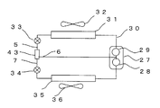
도22는 제6 실시 형태로서, 상기한 기액 분리 장치를 냉동 사이클에 사용한 경우의 제1 냉동 사이클 구성도이다. 도22에 도시한 냉동 사이클 구성도에는 본 실시 형태를 설명하기 위해 필요한 기본적 구성 요소를 도시하고 있다. 즉, 압축기(27)는 제1 실린더(28)와 제2 실린더(29)를 갖고, 압축기에서 흡입한 저온 저압의 기상 냉매는 제1 실린더(28)와 제2 실린더(29)에서 2단으로 압축되고 고온 고압 기상 냉매로 되어 냉매 토출관(30)을 거쳐, 응축기(31)에서 응축기용 송풍기(32)로 보내지는 공기로 방열되어 고압액 냉매로 된다. 그 액 냉매는 제1 감압기(33)에서 감압되어 2상류가 되어, 입구관(5)으로부터 기액 분리 장치(43)로 유입되고, 액상 냉매는 액상 출구관(7)으로부터 나온 후, 제2 감압기(34)에서 또한 감압되고, 증발기(35)로 들어가 증발기용 송풍기(36)로 보내지는 공기로부터 열을 빼앗아 저온 저압의 기상 냉매로 되어 압축기(27)로 흡입된다. 한편, 기액 분리 장치(43)에서 분리된 기상 냉매는 기상 출구관(6)으로부터 제2 실린더(29)로 흡입되므로, 기액 분리 장치(43)에서 분리된 증발에 기여하지 않는 기상 냉매는 제1 실린더(28)에서 압축할 필요가 없어, 압축 동력을 절감할 수 있고 고효율의 운전을 가능하게 할 수 있다.22 is a diagram illustrating the first refrigeration cycle when the above-mentioned gas-liquid separator is used for a refrigeration cycle. The refrigeration cycle block diagram shown in FIG. 22 shows the basic components necessary for explaining the present embodiment. That is, the
「제7 실시 형태」"Seventh embodiment"
도23은 제7 실시 형태로서, 상기한 기액 분리 장치를 냉동 사이클에 사용한 경우의 제2 냉동 사이클 구성도이다. 도23에 도시한 냉동 사이클 구성도에는 본 실시 형태를 설명하기 위해 필요한 기본적 구성 요소를 도시하고 있다. 즉, 압축기(27)는 제1 실린더(28)만을 갖고, 압축기에서 흡입한 저온 저압의 기상 냉매는 제1 실린더(28)에서 압축되고 고온 고압 기상 냉매로 되어 냉매 토출관(30)을 거쳐, 응축기(31)에서 응축기용 송풍기(32)로 보내지는 공기로 방열하여 고압액 냉매로 된다. 그 액 냉매는 제1 감압기(33)에서 감압되어 2상류로 되고, 입구관(5)으로부터 기액 분리 장치(43)로 유입되고, 액상 냉매는 액상 출구관(7)으로부터 증발기(35)로 들어가 증발기용 송풍기(36)로 보내지는 공기로부터 열을 빼앗아 저온 저압의 기상 냉매로 되어 압축기(27)로 흡입된다. 한편, 기액 분리 장치에서 분리된 기상 냉매는 기상 출구관(6)으로부터 증발기 바이패스관(38)을 거쳐 압축기(27)로 흡입된다.FIG. 23 is a diagram of a second refrigeration cycle when the above-described gas-liquid separator is used in a refrigeration cycle. The refrigeration cycle block diagram shown in FIG. 23 shows the basic components necessary for explaining this embodiment. That is, the
기액 분리 장치(43)를 이용하지 않는 경우에는, 감압기(33)에서 감압된 2상류의 기상 냉매도 증발기로 유입되므로, 특히 증발기용 송풍기(36)에서 보내지는 공기 온도가 낮은 경우에는 증발 압력이 저하되고 기상 냉매의 밀도는 작아져 체적 유량이 커지기 때문에, 증발기(35)에서의 압력 손실이 커 증발기(35)의 출구 압력, 즉, 압축기 흡입 압력이 저하되므로 압축 동력이 증대되어 고효율의 운전을 할 수 없게 된다.When the gas-
그에 대해, 본 실시 형태에서 나타낸 바와 같이 기액 분리 장치(43)를 설치하고, 분리된 기상 냉매를 기상 출구관(6)으로부터 증발기 바이패스관(38)을 거쳐 압축기(27)로 흡입시킴으로써 증발에 기여하지 않는 기상 냉매는 증발기(35)로 유입되지 않으므로 증발기(35)에서의 압력 손실을 억제할 수 있고, 압축 동력을 절감할 수 있어 고효율의 운전을 가능하게 할 수 있다.On the other hand, as shown in the present embodiment, a gas-
종래, 냉동 사이클에서 사용되는 기액 분리 장치로서는, 중력에 의해 액을 저류하는 탱크를 이용하거나, 선회류의 원심력에 의해 액상을 외벽에 부착시키고, 중력에 의해 액을 회수하는 기액 분리 장치 등이 이용되고 있었지만, 이러한 구성의 기액 분리 장치에서는 기본적으로 중력이나 원심력 등의 체적력에 의해 밀도가 큰 액상을 분리하는 구조로 되어 있으므로, 기액 분리 장치의 설치 위치나 방향에 자유도가 적은 데 더하여, 탱크나 선회류 발생 장치를 이용하기 때문에 대형의 장치로 되어 있었지만, 본 발명의 기액 분리 장치를 사용함으로써 소형이며 설치 위치나 방향의 자유도가 큰 효과를 발휘하면서, 상기 제6 실시 형태, 제7 실시 형태에서 서술한 바와 같이 고효율의 운전을 가능하게 할 수 있다.Conventionally, as a gas-liquid separator used in a refrigeration cycle, a tank for storing a liquid by gravity or a gas-liquid separator for attaching a liquid to the outer wall by centrifugal force of swirling flow and recovering the liquid by gravity is used. Although the gas-liquid separator of such a structure basically has a structure which separates a liquid density with a high density by volume force, such as gravity and centrifugal force, in addition to having less freedom in the installation position and direction of a gas-liquid separator, In the sixth and seventh embodiments of the present invention, a large-sized device is used because the swirl flow generating device is used. As described above, high efficiency operation can be enabled.
「제8 실시 형태」"Eighth Embodiment"
도24는 제8 실시 형태로서, 상기한 기액 분리 장치를 냉동 사이클에 사용한 경우의 제3 냉동 사이클 구성도이다. 도24는 세퍼레이트형 에어컨의 예이며, 실외 유닛(39)과 실내 유닛(40)으로 구성되고, 냉방 운전시의 사이클을 도시하고 있다. 압축기(27)에서 압축된 고온 고압 기상 냉매에는 냉동기 오일이 혼입되어 있고, 압축기로부터 토출된 기상 냉매에 혼입되는 냉동기 오일량이 많아지면, 냉동 사이클 냉매 유로의 압력 손실이 증가하고, 또한 냉매의 증발열 전달율 및 응축열 전달율이 저하되어 냉동 사이클 효율의 저하의 원인이 된다. 또한, 압축기 기동시에는 압축기 내에 봉입되어 있는 냉동기 오일이 포밍되고, 대량의 냉동기 오일이 기상 냉매에 혼입되어 압축기로부터 토출되어 냉동 사이클로 유출된다. 특히 세퍼레이트형 에어컨의 경우에는, 실내 유닛과 실외 유닛을 접속하는 접속 배관이 설치되어 있고, 이 접속 배관(48)이 긴 경우에는 냉동 사이클로 유출된 냉동기 오일은 장시간 압축기로 복귀되지 않아, 운전 조건에 따라서는 압축기 내의 냉동기 오일이 부족하여 압축기의 신뢰성에 지장을 초래하는 문제가 있었다.Fig. 24 is a third refrigeration cycle diagram when the above-mentioned gas-liquid separator is used for a refrigeration cycle. Fig. 24 is an example of a separate type air conditioner, which is composed of an
그래서, 도24는 상기 과제를 해결하기 위해 압축기(27)의 냉매 토출관에 콤팩트한 기액 분리 장치(43)를 설치하여, 냉동 사이클 효율의 확보 및 압축기의 신뢰성 확보를 도모하는 것이다. 즉, 압축기(27)에서 흡입한 저온 저압의 기상 냉매는 압축기(27)에서 압축되고 고온 고압 기상 냉매로 되어 냉매 토출관(41)을 거쳐, 기액 분리 장치(43)의 입구관(5)으로부터 기액 분리 장치로 유입된다. 압축기(27)에서 압축된 고온 고압 기상 냉매에는 냉동기 오일이 혼입되어 있고, 기액 분리 장 치(43) 내에서 냉동기 오일은 액상으로서, 기상 냉매는 기상으로서 분리되어, 각각 액상 출구관(7) 및 기상 출구관(6)으로부터 취출된다. 액상 출구관(7)을 나온 냉동기 오일은 액 리시버(42), 유량 조정 교축부(45)를 거쳐서 압축기 흡입관(46)으로 흡입되고, 냉동기 오일은 압축기로 복귀된다. 유량 조정 교축부(45)를 설치하고 있는 이유는, 통상의 운전 조건에서는 압축기(27)로부터 토출되는 고온 고압 기상 냉매에 혼입되어 있는 냉동기 오일은 기상 냉매에 비해 적기 때문에, 기액 분리 장치(43)에서 분리한 냉동기 오일을 유량 조정 교축부(45)에서 서서히 압축기(27)로 냉동기 오일을 복귀시키기 위함이다. 또한, 액 리시버(42)를 설치하고 있는 이유는, 압축기 기동시에 압축기 내에 봉입되어 있는 냉동기 오일이 포밍되고 대량의 냉동기 오일이 기상 냉매에 혼입되어 압축기로부터 토출되지만, 이것은 일시적인 현상이기 때문에 기액 분리 장치(43)에서 분리한 냉동기 오일을 일시적으로 액 리시버(42)에 저류하여, 유량 조정 교축부(45)에서 서서히 압축기(27)로 냉동기 오일을 복귀시키기 위함이다. 또한, 기액 분리 장치의 액체 저류부(18)의 용적이 큰 경우에는 반드시 액 리시버는 필요로 하지 않는다.Thus, in order to solve the above problems, FIG. 24 is provided with a compact gas-
한편, 기액 분리 장치(43) 내에서 분리된 기상 냉매는 기상 출구관(6)으로부터 사방 밸브(47)를 거쳐서, 응축기(31)에서 응축기용 송풍기(32)로부터 보내지는 공기로 방열하여 고압액 냉매로 된다. 그 액 냉매는 제1 감압기(33)에서 감압되어 저온 저압의 2상류로 되고, 증발기(35)로 들어가 증발기용 송풍기(36)로 보내지는 공기로부터 열을 빼앗아 저온 저압의 기상 냉매로 되어 압축기(27)로 흡입된다. 따라서, 기액 분리 장치(43) 내에서 냉동기 오일은 액상으로서 분리되고, 액상 출 구관(7)으로부터 액 리시버(42), 유량 조정 교축부(45)를 거쳐서 압축기 흡입관(46)으로 흡입되고, 냉동기 오일은 압축기로 복귀되므로 냉동기 오일이 냉동 사이클로 유출하는 것을 방지할 수 있어 고효율의 냉동 사이클 운전이 가능해지고, 또한 기동시에도 냉동기 오일이 냉동 사이클로 유출되는 것을 방지할 수 있어 신뢰성이 높은 운전이 가능해진다.On the other hand, the gaseous phase refrigerant separated in the gas-
본 발명은 기액 2상류를 협소한 홈을 통과시켜 기상과 액상을 분리하는 기액 분리 장치에 있어서, 기상을 타고 운반되는 액적을 최대한 포착하기 위해 2차 흐름을 이용하는 것, 홈을 기울이는 것, 기액 분리실 단면적 전체를 축방향 기상 상승 유로로 하는 것에 의해 기상으로 반송되는 액적을 효율적으로 포착할 수 있도록 한 것이므로, 냉동 장치의 소형화에 추종할 수 있는 기액 분리 장치의 제공을 가능하게 하는 것은 물론, 냉동 장치의 냉각 성능 개선에 대폭 공헌할 수 있는 것이다.The present invention is a gas-liquid separation device that separates the gaseous phase and the liquid phase through a narrow groove through the gas-liquid two-phase flow, using a secondary flow in order to capture the droplets carried in the gaseous phase to the maximum, tilting the grooves, gas-liquid separation It is possible to efficiently capture the droplets conveyed in the gas phase by using the entire cross-sectional area as the axial gas phase rising passage, thereby enabling the provision of a gas-liquid separation device that can follow the miniaturization of the refrigeration apparatus, as well as the freezing. It can greatly contribute to improving the cooling performance of the device.
도1은 제1 실시 형태의 기액 분리 장치의 단면도.1 is a cross-sectional view of the gas-liquid separation device of the first embodiment.
도2는 도1에 도시하는 기액 분리 장치의 A-A선 단면도.FIG. 2 is a cross-sectional view taken along the line A-A of the gas-liquid separator shown in FIG.
도3은 도2에 도시하는 홈 형성체의 전개 사시도.3 is an exploded perspective view of the groove forming body shown in FIG. 2;
도4는 도3에 도시하는 주류에 대해 경사진 대략 파 형상을 형성한 홈 형성체의 1피치를 도시하는 사시도.FIG. 4 is a perspective view showing one pitch of the groove-formed body in which a substantially wave shape inclined with respect to the mainstream shown in FIG. 3 is formed; FIG.
도5는 제2 실시 형태의 기액 분리 장치의 단면도.Fig. 5 is a sectional view of the gas-liquid separation device of the second embodiment.
도6은 도5에 도시하는 주류에 대해 끝쪽이 넓은 대략 파 형상을 형성한 홈 형성체의 전개 사시도.Fig. 6 is an exploded perspective view of a groove forming body in which a substantially wave shape with a wide end is formed with respect to the mainstream shown in Fig. 5;
도7은 도6에 도시하는 주류에 대해 끝쪽이 넓은 대략 파 형상을 형성한 홈 형성체의 1피치를 도시하는 사시도.FIG. 7 is a perspective view showing one pitch of the groove-formed body in which an approximately wide end shape is formed with respect to the mainstream shown in FIG. 6; FIG.
도8은 제3 실시 형태의 기액 분리 장치의 단면도.Fig. 8 is a sectional view of the gas-liquid separation device of the third embodiment.
도9는 도8에 도시하는 기액 분리 장치의 B-B선 단면도.FIG. 9 is a sectional view taken along the line B-B of the gas-liquid separation device shown in FIG. 8; FIG.
도10은 도4 및 도7에 도시하는 홈 형성체의 단면도.Fig. 10 is a sectional view of the groove forming body shown in Figs. 4 and 7;
도11은 액적의 벽면에의 부착 모델을 도시하는 도면.FIG. 11 shows a model of attachment of droplets to the wall surface; FIG.
도12는 계산으로부터 구해진 홈 형성체의 무차원 길이를 도시하는 도면.Fig. 12 is a diagram showing the dimensionless length of the grooved body obtained from the calculation.
도13은 제4 실시 형태의 기액 분리 장치를 도시하는 단면도.Fig. 13 is a sectional view showing the gas-liquid separation device of the fourth embodiment.
도14는 도13에 도시하는 기액 분리 장치의 A-A 단면도.Fig. 14 is a sectional view taken along the line A-A of the gas-liquid separation device shown in Fig. 13;
도15는 도13에 도시하는 홈 형성체의 전개 사시도.FIG. 15 is an exploded perspective view of the groove forming body shown in FIG. 13; FIG.
도16은 홈(2)을 기울여 형성한 효과를 도시하는 원리 모델도.Fig. 16 is a principle model diagram showing the effect formed by tilting the
도17은 다른 홈 형성체의 일부 확대 단면도.Figure 17 is an enlarged cross sectional view of a portion of another groove formation.
도18은 제5 실시 형태의 기액 분리 장치를 도시하는 단면도.Fig. 18 is a sectional view showing the gas-liquid separation device of the fifth embodiment.
도19는 도18의 C-C 단면도.Fig. 19 is a sectional view taken along the line C-C in Fig. 18;
도20은 도18의 A-A 단면도.20 is a cross-sectional view taken along line A-A of FIG.
도21은 도18에 도시하는 홈 형성체의 전개 사시도.FIG. 21 is an exploded perspective view of the groove forming body shown in FIG. 18; FIG.
도22는 제6 실시 형태로서, 상기한 기액 분리 장치를 냉동 사이클에 사용한 경우의 제1 냉동 사이클 구성도.Fig. 22 is a sixth embodiment of the first refrigeration cycle configuration diagram when the above-mentioned gas-liquid separator is used for a refrigeration cycle.
도23은 제7 실시 형태로서, 상기한 기액 분리 장치를 냉동 사이클에 사용한 경우의 제2 냉동 사이클 구성도.FIG. 23 is a diagram of a second refrigeration cycle when the above-mentioned gas-liquid separator is used for a refrigeration cycle.
도24는 제8 실시 형태로서, 상기한 기액 분리 장치를 냉동 사이클에 사용한 경우의 제3 냉동 사이클 구성도.Fig. 24 is a third refrigeration cycle diagram when the above-mentioned gas-liquid separator is used for a refrigeration cycle.
<도면의 주요 부분에 대한 부호의 설명><Explanation of symbols for the main parts of the drawings>
1 : 기액 분리실1: gas-liquid separation chamber
2 : 홈2: home
3 : 급확대부3: rapid expansion unit
4 : 홈 형성체4: groove forming body
5 : 입구관5: entrance tube
6 : 기상 출구관6: weather outlet pipe
7 : 액상 출구관7: liquid outlet pipe
8 : 출구 구획체8: outlet compartment
9 : 홈 정상점 가상 원9: home top point virtual circle
10 : 외곽체10: outline
11 : 외곽체 B11: outline B
12 : 협소 공간12: narrow space
13 : 하축관부13: lower shaft pipe part
14 : 액적14: Droplet
15 : 중심선15: centerline
16 : 입구 구획체16: inlet compartment
17 : 상축관부17: upper shaft pipe
18 : 액 저류부18: liquid storage part
19 : 유입실19: inflow chamber
20 : 2차 흐름20: secondary flow
21 : 기상 유입 단부21: weather inlet end
22 : 연통 구멍22: communication hole
23 : 홈으로부터 나오는 기상의 흐름 방향23: flow direction of the weather from the groove
24 : 선회류24: swirl flow
25 : 축방향 기상 상승 속도 Ua 25: axial meteorological ascent rate Ua
26 : 비드26: Bead
27 : 압축기27: compressor
28 : 제1 실린더28: first cylinder
29 : 제2 실린더29: second cylinder
30 : 토출관30: discharge tube
31 : 응축기31: condenser
32 : 응축기용 송풍기32: blower for condenser
33 : 제1 감압기33: first pressure reducer
34 : 제2 감압기34: second pressure reducer
35 : 증발기35: evaporator
36 : 증발기용 송풍기36 blower for evaporator
37 : 구획 원통37: compartment cylinder
38 : 증발기 바이패스관38: evaporator bypass pipe
39 : 실외 유닛39: outdoor unit
40 : 실내 유닛40: indoor unit
41 : 냉매 토출관41: refrigerant discharge tube
42 : 액 리시버42: liquid receiver
43 : 기액 분리 장치43: gas-liquid separator
45 : 유량 조정 교축부45: flow adjustment throttle
46 : 압축기 흡입관46: compressor suction pipe
47 : 사방 밸브47: four-way valve
48 : 접속 배관48: connection piping
Claims (13)
Applications Claiming Priority (2)
| Application Number | Priority Date | Filing Date | Title |
|---|---|---|---|
| JP2008038034A JP5395358B2 (en) | 2008-01-23 | 2008-01-23 | A gas-liquid separator and a refrigeration apparatus including the gas-liquid separator. |
| JPJP-P-2008-038034 | 2008-01-23 |
Publications (1)
| Publication Number | Publication Date |
|---|---|
| KR20090081320A true KR20090081320A (en) | 2009-07-28 |
Family
ID=40923987
Family Applications (1)
| Application Number | Title | Priority Date | Filing Date |
|---|---|---|---|
| KR1020080131025A KR20090081320A (en) | 2008-01-23 | 2008-12-22 | Gas-liquid separator and refrigerating apparatus equipped therewith |
Country Status (3)
| Country | Link |
|---|---|
| JP (1) | JP5395358B2 (en) |
| KR (1) | KR20090081320A (en) |
| CN (1) | CN101493275B (en) |
Cited By (2)
| Publication number | Priority date | Publication date | Assignee | Title |
|---|---|---|---|---|
| CN110013708A (en) * | 2019-04-26 | 2019-07-16 | 深圳市氢蓝时代动力科技有限公司 | A kind of gas-liquid separation device |
| EP3627076A4 (en) * | 2017-06-21 | 2020-06-17 | Gree Electric Appliances (Wuhan) Co., Ltd. | Oil separator, compressor and air conditioner |
Families Citing this family (21)
| Publication number | Priority date | Publication date | Assignee | Title |
|---|---|---|---|---|
| JP2012057924A (en) * | 2010-09-13 | 2012-03-22 | Nichirei Kogyo Kk | Gas-liquid separator and refrigeration device including the same |
| WO2012095947A1 (en) * | 2011-01-11 | 2012-07-19 | 国立大学法人東京大学 | Heat exchanger for thermal engine |
| WO2012108149A1 (en) * | 2011-02-08 | 2012-08-16 | パナソニック株式会社 | Gas liquid separator and freeze cycle device |
| JP5803263B2 (en) * | 2011-05-18 | 2015-11-04 | 富士電機株式会社 | Gas-liquid separator |
| JP5864951B2 (en) * | 2011-08-18 | 2016-02-17 | 株式会社テイエルブイ | heat pump |
| JP5977952B2 (en) * | 2012-02-03 | 2016-08-24 | ジョンソンコントロールズ ヒタチ エア コンディショニング テクノロジー(ホンコン)リミテッド | Economizer and refrigerator |
| CN102853591A (en) * | 2012-09-03 | 2013-01-02 | 梁嘉麟 | Structural form of small-volume low-pressure circulating barrel structure in application of liquid pump in high-rise refrigeration air conditioner system set |
| WO2016181558A1 (en) * | 2015-05-14 | 2016-11-17 | 三菱電機株式会社 | Compressor muffler |
| JP6631489B2 (en) | 2016-04-08 | 2020-01-15 | 株式会社デンソー | Heat exchanger |
| WO2017175724A1 (en) * | 2016-04-08 | 2017-10-12 | 株式会社デンソー | Heat exchanger |
| CN105716336B (en) * | 2016-04-14 | 2019-02-01 | 福建欣隆环保股份有限公司 | A kind of industrial, commercial MW grades of CO 2 trans-critical heat pump oil eliminators |
| CN105895913B (en) * | 2016-05-04 | 2019-08-16 | 北京化工大学 | A method of preparing two-dimensional material |
| JP6539640B2 (en) * | 2016-12-27 | 2019-07-03 | 株式会社不二工機 | Refrigerant container |
| CN106895616B (en) * | 2017-03-22 | 2022-10-04 | 江苏中关村科技产业园节能环保研究有限公司 | Gas-liquid separator with surface tension type groove body |
| JP6833013B2 (en) * | 2017-03-24 | 2021-02-24 | 三菱電機株式会社 | Refrigeration cycle equipment |
| CN107287610B (en) * | 2017-07-07 | 2024-01-12 | 浙江嘉化能源化工股份有限公司 | High-electric-density low-electricity consumption electrolytic cell device and gas-liquid separation method thereof |
| ES2904309T3 (en) | 2017-09-28 | 2022-04-04 | Mitsubishi Electric Corp | oil separator and air conditioner with the same |
| JP2019100695A (en) * | 2017-12-04 | 2019-06-24 | パナソニックIpマネジメント株式会社 | Refrigeration cycle device and method for driving refrigeration cycle device |
| WO2019130393A1 (en) * | 2017-12-25 | 2019-07-04 | 三菱電機株式会社 | Separator and refrigeration cycle device |
| CN114234498B (en) * | 2021-12-21 | 2023-03-10 | 珠海格力电器股份有限公司 | Guide plate, gas-liquid separator, compressor assembly and air conditioner |
| CN114992920B (en) * | 2022-04-22 | 2023-11-28 | 美的集团武汉暖通设备有限公司 | Gas-liquid separator, air conditioner, control method of air conditioner and storage medium |
Family Cites Families (6)
| Publication number | Priority date | Publication date | Assignee | Title |
|---|---|---|---|---|
| JPH0618127A (en) * | 1992-07-01 | 1994-01-25 | Daikin Ind Ltd | Oil separator |
| CN2347133Y (en) * | 1998-10-20 | 1999-11-03 | 无锡市灵通机械厂 | High effective heat transfering tube with inner fins |
| CN2483068Y (en) * | 2001-04-26 | 2002-03-27 | 台湾公害处理工程股份有限公司 | Eddy and concave trough blade type gas/liquid separator |
| JP4063179B2 (en) * | 2003-08-28 | 2008-03-19 | 松下電器産業株式会社 | Oil separator |
| JP4268994B2 (en) * | 2005-11-14 | 2009-05-27 | 日冷工業株式会社 | Gas-liquid separator and refrigeration apparatus equipped with the gas-liquid separator |
| CN2898730Y (en) * | 2006-01-13 | 2007-05-09 | 浙江春晖智能控制股份有限公司 | Gas-liquid separator |
-
2008
- 2008-01-23 JP JP2008038034A patent/JP5395358B2/en active Active
- 2008-12-22 KR KR1020080131025A patent/KR20090081320A/en not_active Application Discontinuation
-
2009
- 2009-01-15 CN CN2009100021276A patent/CN101493275B/en active Active
Cited By (3)
| Publication number | Priority date | Publication date | Assignee | Title |
|---|---|---|---|---|
| EP3627076A4 (en) * | 2017-06-21 | 2020-06-17 | Gree Electric Appliances (Wuhan) Co., Ltd. | Oil separator, compressor and air conditioner |
| US11131488B2 (en) | 2017-06-21 | 2021-09-28 | Gree Electric Appliances (Wuhan) Co., Ltd | Oil separator, compressor and air conditioner |
| CN110013708A (en) * | 2019-04-26 | 2019-07-16 | 深圳市氢蓝时代动力科技有限公司 | A kind of gas-liquid separation device |
Also Published As
| Publication number | Publication date |
|---|---|
| CN101493275A (en) | 2009-07-29 |
| JP5395358B2 (en) | 2014-01-22 |
| JP2009174836A (en) | 2009-08-06 |
| CN101493275B (en) | 2013-04-17 |
Similar Documents
| Publication | Publication Date | Title |
|---|---|---|
| KR20090081320A (en) | Gas-liquid separator and refrigerating apparatus equipped therewith | |
| CN105492841B (en) | Ejector-type kind of refrigeration cycle and injector | |
| US7386994B2 (en) | Oil separator and cooling-cycle apparatus using the same | |
| US5692389A (en) | Flash tank economizer | |
| US3563053A (en) | Suctiin accumulator | |
| JP5143040B2 (en) | Gas-liquid separator and refrigeration cycle apparatus equipped with the gas-liquid separator | |
| EP2778569B1 (en) | Air conditioner | |
| US7086248B2 (en) | Ejector cycle device | |
| CN105324581B (en) | Injector | |
| US6389842B1 (en) | Accumulator-dehydrator assembly with anti-bump expansion chamber “J”-tube | |
| JP3215614B2 (en) | Refrigeration cycle and refrigeration cycle parts for air conditioners | |
| JP5634549B2 (en) | A gas-liquid separator and a refrigeration apparatus including the gas-liquid separator. | |
| CN105371533A (en) | Air conditioner | |
| CN107044749A (en) | For heating, the lubricant separator of ventilating and air conditioning system | |
| KR101340532B1 (en) | Oil separator and air conditioner comprising the same | |
| EP3517859B1 (en) | Refrigeration cycle apparatus | |
| WO2014083673A1 (en) | Compressor, refrigeration cycle device, and heat pump hot-water supply device | |
| CN103759477A (en) | Refrigerating circulation device | |
| KR100819015B1 (en) | Internal oil separator for compressor | |
| CN113864930A (en) | Air conditioning system | |
| JP2005233470A (en) | Gas-liquid separator | |
| JP6710294B2 (en) | Compressor and refrigeration cycle device | |
| CN216203957U (en) | Air conditioning system | |
| KR102536383B1 (en) | Device including a refrigerant cycle | |
| JP2005265387A (en) | Gas-liquid separator |
Legal Events
| Date | Code | Title | Description |
|---|---|---|---|
| WITN | Withdrawal due to no request for examination |