EP1568955B1 - Oil separator and cooling-cycle apparatus using the same - Google Patents
Oil separator and cooling-cycle apparatus using the same Download PDFInfo
- Publication number
- EP1568955B1 EP1568955B1 EP05000070A EP05000070A EP1568955B1 EP 1568955 B1 EP1568955 B1 EP 1568955B1 EP 05000070 A EP05000070 A EP 05000070A EP 05000070 A EP05000070 A EP 05000070A EP 1568955 B1 EP1568955 B1 EP 1568955B1
- Authority
- EP
- European Patent Office
- Prior art keywords
- oil
- casing
- refrigerant
- tube
- gaseous refrigerant
- Prior art date
- Legal status (The legal status is an assumption and is not a legal conclusion. Google has not performed a legal analysis and makes no representation as to the accuracy of the status listed.)
- Ceased
Links
- 239000003507 refrigerant Substances 0.000 claims description 129
- 238000007599 discharging Methods 0.000 claims description 9
- 230000002093 peripheral effect Effects 0.000 claims description 9
- 238000001914 filtration Methods 0.000 description 9
- 238000000926 separation method Methods 0.000 description 7
- 239000007788 liquid Substances 0.000 description 6
- 230000006835 compression Effects 0.000 description 4
- 238000007906 compression Methods 0.000 description 4
- 238000011084 recovery Methods 0.000 description 4
- 230000005484 gravity Effects 0.000 description 3
- 239000002245 particle Substances 0.000 description 3
- 238000005452 bending Methods 0.000 description 2
- 238000010586 diagram Methods 0.000 description 2
- 230000000694 effects Effects 0.000 description 2
- 238000009434 installation Methods 0.000 description 2
- 239000000203 mixture Substances 0.000 description 2
- 238000007792 addition Methods 0.000 description 1
- 238000001816 cooling Methods 0.000 description 1
- 230000007423 decrease Effects 0.000 description 1
- 238000003780 insertion Methods 0.000 description 1
- 230000037431 insertion Effects 0.000 description 1
- 238000005461 lubrication Methods 0.000 description 1
- 238000004519 manufacturing process Methods 0.000 description 1
- 238000012986 modification Methods 0.000 description 1
- 230000004048 modification Effects 0.000 description 1
- 230000000630 rising effect Effects 0.000 description 1
- 238000006467 substitution reaction Methods 0.000 description 1
- 238000010792 warming Methods 0.000 description 1
Images


Classifications
-
- F—MECHANICAL ENGINEERING; LIGHTING; HEATING; WEAPONS; BLASTING
- F25—REFRIGERATION OR COOLING; COMBINED HEATING AND REFRIGERATION SYSTEMS; HEAT PUMP SYSTEMS; MANUFACTURE OR STORAGE OF ICE; LIQUEFACTION SOLIDIFICATION OF GASES
- F25B—REFRIGERATION MACHINES, PLANTS OR SYSTEMS; COMBINED HEATING AND REFRIGERATION SYSTEMS; HEAT PUMP SYSTEMS
- F25B43/00—Arrangements for separating or purifying gases or liquids; Arrangements for vaporising the residuum of liquid refrigerant, e.g. by heat
- F25B43/02—Arrangements for separating or purifying gases or liquids; Arrangements for vaporising the residuum of liquid refrigerant, e.g. by heat for separating lubricants from the refrigerant
-
- B—PERFORMING OPERATIONS; TRANSPORTING
- B01—PHYSICAL OR CHEMICAL PROCESSES OR APPARATUS IN GENERAL
- B01D—SEPARATION
- B01D19/00—Degasification of liquids
- B01D19/0042—Degasification of liquids modifying the liquid flow
- B01D19/0052—Degasification of liquids modifying the liquid flow in rotating vessels, vessels containing movable parts or in which centrifugal movement is caused
- B01D19/0057—Degasification of liquids modifying the liquid flow in rotating vessels, vessels containing movable parts or in which centrifugal movement is caused the centrifugal movement being caused by a vortex, e.g. using a cyclone, or by a tangential inlet
-
- F—MECHANICAL ENGINEERING; LIGHTING; HEATING; WEAPONS; BLASTING
- F25—REFRIGERATION OR COOLING; COMBINED HEATING AND REFRIGERATION SYSTEMS; HEAT PUMP SYSTEMS; MANUFACTURE OR STORAGE OF ICE; LIQUEFACTION SOLIDIFICATION OF GASES
- F25B—REFRIGERATION MACHINES, PLANTS OR SYSTEMS; COMBINED HEATING AND REFRIGERATION SYSTEMS; HEAT PUMP SYSTEMS
- F25B2400/00—General features or devices for refrigeration machines, plants or systems, combined heating and refrigeration systems or heat-pump systems, i.e. not limited to a particular subgroup of F25B
- F25B2400/02—Centrifugal separation of gas, liquid or oil
-
- F—MECHANICAL ENGINEERING; LIGHTING; HEATING; WEAPONS; BLASTING
- F25—REFRIGERATION OR COOLING; COMBINED HEATING AND REFRIGERATION SYSTEMS; HEAT PUMP SYSTEMS; MANUFACTURE OR STORAGE OF ICE; LIQUEFACTION SOLIDIFICATION OF GASES
- F25B—REFRIGERATION MACHINES, PLANTS OR SYSTEMS; COMBINED HEATING AND REFRIGERATION SYSTEMS; HEAT PUMP SYSTEMS
- F25B2500/00—Problems to be solved
- F25B2500/01—Geometry problems, e.g. for reducing size
Definitions
- the present invention relates to a cooling-cycle apparatus using an oil separator, and more particularly, an oil separator for separating oil from gas in a cyclone separation manner, and a cooling-cycle apparatus using the oil separator.
- a cooling-cycle apparatus is an apparatus installed in an air conditioner, refrigerator, etc. for cooling or warming a room, or keeping food at low temperatures.
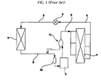
- Fig. 1 is a diagram of a conventional cooling-cycle apparatus.
- the cooling-cycle apparatus comprises a compressor 2, a condenser 4, an expander 6, an evaporator 8, and refrigerant conveyance tubes 9.
- the compressor 2 compresses a gaseous refrigerant having a low-temperature and low-pressure to a high-temperature and high-pressure gas
- the condenser 4 condenses the high-temperature and high-pressure gaseous refrigerant to a liquid by taking heat from the gaseous refrigerant.
- the liquefied high-temperature and high-pressure refrigerant is depressurized by means of the expander 6 to a two-phase refrigerant.
- the two-phase refrigerant is a mixture of gas and liquid and has a low-pressure and low-temperature.
- the depressurized refrigerant flows into the evaporator 8, and is then vaporized while absorbing heat from air around the evaporator 8.
- the compressor 2, the condenser 4, the expander 6 and the evaporator 8 are connected to one another by way of the refrigerant conveyance tubes 9 to enable the refrigerant to circulate therethrough.
- the compressor 2 comprises a compression unit having a refrigerant compression chamber, a motor unit for driving the compression unit, and an oil pump for the lubrication of both the compression unit and the motor.
- the oil separator 10 serves to separate oil, discharged from the compressor 2 as shown in a dash-lined arrow, from the gaseous refrigerant, likewise discharged from the compressor 2 as shown in solid-lined arrows.
- Not described reference numeral 2a designates an accumulator, which is mounted at the refrigerant conveyance tube 9 near an inlet of the compressor 2.
- the accumulator 2a is adapted to catch the liquefied refrigerant, not evaporated in the evaporator 8, so as to prevent it from flowing into the compressor 2.
- Fig. 2 is a longitudinal sectional view illustrating the conventional oil separator.
- the oil separator 10 comprises a casing 12 defining an interior space, an inflow tube 14 for supplying the oil and the gaseous refrigerant into the casing 12, a filtering member 16 mounted in an intermediate region of the casing 12 and adapted to filter oil while allowing the passage of the gaseous refrigerant, causing the filtered oil to drop into a lower region of the casing 12, an oil outflow tube 18 for delivering the dropped oil in the lower region of the casing 12 to the compressor, and a refrigerant outflow tube 20 for supplying the refrigerant, passed through the filtering member 16, to the condenser.
- the compressor 2 When the compressor 2 starts to drive, the high-temperature and high-pressure gaseous refrigerant (shown in the solid-line arrows) and the oil (shown in the dash-lined arrow) are simultaneously discharged from the compressor 2, and then are supplied into the casing 12 of the oil separator 10 through the inflow tube 14.
- the oil collides with the filtering member 16 and forms oil droplets.
- the oil droplets are easy to drop into the lower region of the casing 12 by gravity, and then return back to the compressor 2 through the oil outflow tube 18.
- the gaseous refrigerant supplied into the casing 12 of the oil separator 10, is discharged through the refrigerant outflow tube 20 after passing through the filtering member 16.
- the gaseous refrigerant, discharged from the outflow tube 20, is condensed while passing through the condenser 4 by discharging heat thereof to the outside, and is successively depressurized while passing through the expander 6 to a two-phase, namely, liquid-containing gaseous refrigerant having a low-pressure and low-temperature.
- the depressurized two-phase refrigerant flows into the evaporator 8 and is then vaporized by absorbing heat from air around the evaporator 8. Finally, the gaseous refrigerant returns to the compressor 2.
- the above described conventional oil separator 10 having a configuration in that the filtering member 16 is mounted therein to filter the oil from the gaseous refrigerant, however, suffers from increased manufacturing costs and complicated installation operation due to the existence of the filtering member 16, and also has a limitation to reduce the overall size thereof. Furthermore, the filtering member 16 fails to completely intercept the passage of the oil, resulting in a low degree of oil separation efficiency.
- part of the oil supplied into the casing 12 passes through the filtering member 16 and inevitably circulates through the cooling-cycle apparatus together with the refrigerant, causing only a small amount of the oil to return to the compressor 2 through the oil separator 10 and the oil outflow tube 18.
- This requires filling the cooling-cycle apparatus with an excessive amount of oil over an appropriate value. The greater the amount of the oil circulating through the cooling-cycle apparatus, the lower the efficiency of the cooling-cycle apparatus.
- JP 10-185367 A discloses an oil separator for separating oil contained in a gas phase refrigerant.
- This oil separator comprises a substantially cylindrical casing defining an interior space, an inflow tube circumferentially or radially inserted into the cylindrical side wall of the casing and adapted to supply oil and gaseous refrigerant into the interior space of the casing in a circumferential direction, and a refrigerant outflow tube for discharging gaseous refrigerant separated form the oil from the casing.
- US 2002/0100291 A1 discloses another oil separator having a cylindrical portion, a horizontal inlet for incoming gas/oil mixture, an outlet for separated gas, a lower portion, and an outlet for separated oil at the bottom thereof.
- the lower portion decreases in diameter as it proceeds from top to bottom, thereby providing for an increase in centrifugal force within the oil separator and greater separation of oil.
- An oil separator comprises a casing defining an interior space; an inflow tube connected to a circumferential position of the casing and adapted to supply oil and gaseous refrigerant into the interior space of the casing for allowing them to be separated from each other while flowing in a swirl pattern; and a refrigerant outflow tube for discharging the gaseous refrigerant, separated from the oil, from the casing.
- the casing may be connected with an oil outflow tube for discharging the oil, separated from the gaseous refrigerant, from the casing.
- the casing may include a cylindrical portion, and a conical portion defined under the cylindrical portion.
- the inflow tube may be a straight tube inserted into the casing to come into contact with an inner periphery of the casing.
- the inflow tube may be inserted into the casing so that an angle formed by an imaginary line, along which the inflow tube is inserted into the casing, and an imaginary line connecting between a refrigerant and oil outlet end of the inflow tube and a center of the casing is in a range of 85° to 95°.
- the inflow tube may be a bent tube inserted into the casing to extend toward a casing center axis and having a bent refrigerant and oil outlet end.
- the inflow tube may be positioned so that a refrigerant and oil outlet end thereof is kept at a level higher than a refrigerant inlet end of the refrigerant outflow tube.
- a cooling-cycle apparatus using an oil separator comprises a compressor for compressing gaseous refrigerant and discharging the compressed gaseous refrigerant along with oil contained therein; the oil separator for separating the oil and the gaseous refrigerant, discharged from the compressor, from each other by flowing them in a swirl pattern; and an oil outflow tube for returning the oil, separated in the oil separator, to the compressor.
- the oil separator may comprise: a casing defining an interior space; an inflow tube connected to a circumferential position of the casing and adapted to supply oil and gaseous refrigerant into the interior space of the casing in a circumferential direction; and a refrigerant outflow tube for discharging the gaseous refrigerant, separated from the oil, from the casing.
- the casing may include a cylindrical portion, and a conical portion defined under the cylindrical portion.
- the inflow tube may be a straight tube eccentrically inserted into the casing.
- the inflow tube may be a straight tube inserted into the casing to come into contact with an inner periphery of the casing.
- the inflow tube may be inserted into the casing so that an angle formed by an imaginary line, along which the inflow tube is inserted into the casing, and an imaginary line connecting between a refrigerant and oil outlet end of the inflow tube and a center of the casing is in a range of 85° to 95°.
- the inflow tube may be a bent tube having a bent refrigerant and oil outlet end.
- the outlet end of the bent tube may be configured so that a bending angle thereof is greater than 0° and less than 90°.
- the bent tube may be inserted into the casing to extend toward a casing center axis.
- the inflow tube may be positioned so that a refrigerant and oil outlet end thereof is kept at a level higher than a refrigerant inlet end of the refrigerant outflow tube.
- the refrigerant outflow tube may be positioned so that a refrigerant inlet end thereof is located within a range of 30% to 70% of the entire height of the casing.
- the refrigerant outflow tube may be a straight tube inserted vertically into the casing through an upper surface of the casing.
- the refrigerant outflow tube may be a bent tube inserted horizontally into the casing through a peripheral wall of the casing and having a bent refrigerant inlet end.
- Fig. 3 is a partially cut-away perspective view illustrating a cooling-cycle apparatus using an oil separator.
- the cooling-cycle apparatus using the oil separator comprises a compressor 50, a condenser, an expander, an evaporator, refrigerant conveyance tubes, an oil separator 60, and an oil outflow tube 70.
- the compressor 50 compresses a gaseous refrigerant and discharges it, along with oil contained therein.
- the condenser the high-temperature and high-pressure gaseous refrigerant is condensed to a liquid through heat emission.
- the liquefied refrigerant is depressurized by the expander to a two-phase, namely, liquid-containing gaseous refrigerant having a low-pressure and low-temperature.
- the depressurized refrigerant is vaporized while absorbing heat from air around the evaporator.
- the compressor, the condenser, the expander and the evaporator are connected to one another by way of the refrigerant conveyance tubes to enable the refrigerant to circulate therethrough.
- the oil and the gaseous refrigerant, discharged from the compressor 50, are separated from each other within the oil separator 60 as they flow in a swirl pattern, and then are returned to the compressor 50 via the oil outflow tube 70.
- the compressor 50 is connected at a circumferential position thereof to an end of a refrigerant suction tube 51, and the other end of the refrigerant suction tube 51 is connected to a lower end of an accumulator 52.
- the accumulator 52 is adapted to catch the liquefied refrigerant, not evaporated by the evaporator, so as to prevent it from flowing into the compressor 50.
- the accumulator 52 is connected at an upper end thereof to an evaporator connection tube 53, which guides the refrigerant passed through the evaporator.
- the oil separator 60 comprises a casing 62 defining an interior space, an inflow tube 64 connected to a circumferential portion of the casing 62 for supplying the oil and the gaseous refrigerant into the casing 62 in a circumferential direction, and a refrigerant outflow tube 66 for discharging the gaseous refrigerant, separated from the oil, upward from the casing 62.
- the oil outflow tube 70 is provided with a capillary tube 71 for facilitating the recovery of the oil, and is connected to one of the refrigerant suction tube 51, the accumulator 52 and the evaporator connection tube 53.
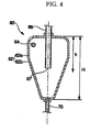
- Figs. 4 and 5 are a longitudinal sectional view and a cross sectional view, respectively, illustrating the oil separator shown in Fig. 3 .
- the casing 62 of the oil separator 60 includes a cylindrical portion 62a to which the inflow tube 64 is inserted, and a conical portion 62b defined under the cylindrical portion 62a.
- the inflow tube 64 is a straight tube eccentrically inserted in the casing 62 for supplying the oil and the gaseous refrigerant into the casing 62 in a direction deviating from a casing center axis.
- the inflow tube 64 is inserted into the casing 62 to come into contact with an inner periphery of the casing 62.
- an angle ⁇ formed by an imaginary line A-A, along which the inflow tube 64 is inserted into the casing 62, and an imaginary line B-B connecting between a refrigerant and oil outlet end 65 of the inflow tube 64 and a center of the casing 62 is in a range of 85° to 95°.
- the inflow tube 64 is positioned so that the refrigerant and oil outlet end 65 thereof is kept at a level higher than a refrigerant inlet end 67 of the refrigerant outflow tube 66.
- the refrigerant outflow tube 66 is inserted vertically into the casing 62 through an upper surface of the casing 62 to extend in the casing 62 by a predetermined length h.
- a swirl flow path between an inner peripheral wall surface of the casing 62 and an outer peripheral surface of the refrigerant outflow tube 66.
- the refrigerant outflow tube 66 is positioned so that the refrigerant inlet end 67 thereof is located within a range of 30% to 70% of the entire height H of the casing 62. This prevents part of the oil, flowing within an upper or middle region of the casing 62 in a swirl pattern, from flowing into the refrigerant outflow tube 66.
- a ratio of the length h of the refrigerant outflow tube 66 extending in the casing 62 to the entire height H of the casing 62 is from 0.3 to 0.7.
- the high-temperature and high-pressure gaseous refrigerant is discharged from the compressor 50, along with the oil contained in the compressor 50. Both the discharged gaseous refrigerant and the oil flow into the casing 62 of the oil separator 60 through the inflow tube 64.
- the gaseous refrigerant and the oil are supplied into the casing 62 in a direction of the refrigerant and oil outlet end 65 of the tube 64, namely, in a direction deviating from the casing center axis, thereby flowing in a swirl pattern along inner peripheral wall surfaces of both the cylindrical portion 62a and the conical portion 62b.
- the oil separated from the gaseous refrigerant, runs down the inner peripheral wall surface of the casing 62 into a lower region of the casing 62, and is discharged through the oil outflow tube 70, so as to be returned to the compressor 50.
- the gaseous refrigerant, separated from the oil is gathered in the center of the lower region of the casing 62, specifically, of the conical portion 62b, and forms a rising swirl stream.
- the gaseous refrigerant flows upward in a swirl pattern, the oil, still remaining in the refrigerant, can be separated due to gravity.
- the upwardly flown gaseous refrigerant is discharged from the casing 62 through the refrigerant outflow tube 66.
- the gaseous refrigerant After passing through the outflow tube 66, the gaseous refrigerant is condensed through heat emission, and then the liquefied refrigerant is depressurized while passing through the expander to the two-phase, namely, liquid-containing gaseous refrigerant having a low-pressure and low-temperature. After that, while passing through the evaporator, the depressurized refrigerant is vaporized while absorbing heat from air around the evaporator, thereby being circulated into the compressor in a gaseous state, along with the oil passed through the oil outflow tube 70.
- Fig. 6 is a cross sectional view illustrating oil separator.
- the oil separator 60' of Fig. 6 comprises an inflow tube 64' in the form of a bent tube. That is, the inflow tube 64' has a bent refrigerant and oil outlet end 65'.
- a bending angle ⁇ of the outlet end 65' is greater than 0° and less than 90°.
- the bent tube 64' is inserted into the casing 62 to extend toward the casing center axis.
- Fig. 7 is a longitudinal sectional view illustrating an oil separator in accordance with an embodiment of the present invention.
- the oil separator 60" of the invention comprises a refrigerant outflow tube 66', which is inserted horizontally into the casing 62 through a peripheral wall thereof, and has a bent refrigerant inlet end 67'.
- the oil separator of the invention further comprises an inflow tube 64", which is inserted vertically into the casing 62 through the upper surface of the casing 62, and has a bent outlet 65".
- an oil separator and a cooling-cycle apparatus using the same according to the present invention has several advantages as follows:
- an inflow tube is connected to a casing of the oil separator to supply oil and gaseous refrigerant into the casing, so as to cause them to be separated from each other while flowing in a swirl pattern in the casing in a cyclone separation manner, resulting in an improved oil separation efficiency.
- the cooling-cycle apparatus of present invention can achieve an improvement in an oil recovery efficiency and reliability thereof.
- oil particles are conglomerated through collision so as to be centrifugally separated from the gaseous refrigerant as a result of swirl flowing of the oil within the casing. This has the effect of eliminating the use of a conventional oil filtering member, simplifying the structure of the oil separator and achieving an inexpensive oil separator.
- the inflow tube takes the form of a straight tube eccentrically inserted into the casing, or takes the form of a bent tube having a bent refrigerant and oil outlet end. This enables the gaseous refrigerant and the oil to be supplied into the casing in a direction deviating from a casing center axis, and allows the tube to be easily installed to the casing.
- the inflow tube is positioned so that the refrigerant and oil outlet end thereof is kept at a level higher than a refrigerant inlet end of a refrigerant outflow tube, it is possible to prevent part of the oil supplied into the casing from directly flowing into the outflow tube, resulting in an increased oil recovery efficiency.
- the refrigerant outflow tube takes the form of a straight tube protruding vertically into the casing through an upper surface of the casing, or takes the form of a bent tube protruding horizontally into the casing through a peripheral wall of the casing and having a bent inlet, the discharge of the gaseous refrigerant as well as the installation of the outflow tube can be simplified.
Landscapes
- Engineering & Computer Science (AREA)
- Chemical & Material Sciences (AREA)
- Analytical Chemistry (AREA)
- Power Engineering (AREA)
- Physics & Mathematics (AREA)
- Mechanical Engineering (AREA)
- Thermal Sciences (AREA)
- General Engineering & Computer Science (AREA)
- Chemical Kinetics & Catalysis (AREA)
- Compressor (AREA)
- Cyclones (AREA)
- Applications Or Details Of Rotary Compressors (AREA)
Description
- The present invention relates to a cooling-cycle apparatus using an oil separator, and more particularly, an oil separator for separating oil from gas in a cyclone separation manner, and a cooling-cycle apparatus using the oil separator.
- As well known to those skilled in the art, a cooling-cycle apparatus is an apparatus installed in an air conditioner, refrigerator, etc. for cooling or warming a room, or keeping food at low temperatures.
-
Fig. 1 is a diagram of a conventional cooling-cycle apparatus. - As shown in
Fig. 1 , the cooling-cycle apparatus comprises a compressor 2, a condenser 4, anexpander 6, an evaporator 8, and refrigerant conveyance tubes 9. The compressor 2 compresses a gaseous refrigerant having a low-temperature and low-pressure to a high-temperature and high-pressure gas, and the condenser 4 condenses the high-temperature and high-pressure gaseous refrigerant to a liquid by taking heat from the gaseous refrigerant. The liquefied high-temperature and high-pressure refrigerant is depressurized by means of theexpander 6 to a two-phase refrigerant. Here, the two-phase refrigerant is a mixture of gas and liquid and has a low-pressure and low-temperature. The depressurized refrigerant flows into the evaporator 8, and is then vaporized while absorbing heat from air around the evaporator 8. The compressor 2, the condenser 4, theexpander 6 and the evaporator 8 are connected to one another by way of the refrigerant conveyance tubes 9 to enable the refrigerant to circulate therethrough. - The compressor 2 comprises a compression unit having a refrigerant compression chamber, a motor unit for driving the compression unit, and an oil pump for the lubrication of both the compression unit and the motor.
- Installed between the compressor 2 and the condenser 4 is an
oil separator 10. Theoil separator 10 serves to separate oil, discharged from the compressor 2 as shown in a dash-lined arrow, from the gaseous refrigerant, likewise discharged from the compressor 2 as shown in solid-lined arrows. - Not described reference numeral 2a designates an accumulator, which is mounted at the refrigerant conveyance tube 9 near an inlet of the compressor 2. The accumulator 2a is adapted to catch the liquefied refrigerant, not evaporated in the evaporator 8, so as to prevent it from flowing into the compressor 2.
-
Fig. 2 is a longitudinal sectional view illustrating the conventional oil separator. - The
oil separator 10 comprises acasing 12 defining an interior space, an inflow tube 14 for supplying the oil and the gaseous refrigerant into thecasing 12, a filtering member 16 mounted in an intermediate region of thecasing 12 and adapted to filter oil while allowing the passage of the gaseous refrigerant, causing the filtered oil to drop into a lower region of thecasing 12, anoil outflow tube 18 for delivering the dropped oil in the lower region of thecasing 12 to the compressor, and arefrigerant outflow tube 20 for supplying the refrigerant, passed through the filtering member 16, to the condenser. - Now, the operation of the conventional cooling-cycle apparatus configured as stated above will be explained.
- When the compressor 2 starts to drive, the high-temperature and high-pressure gaseous refrigerant (shown in the solid-line arrows) and the oil (shown in the dash-lined arrow) are simultaneously discharged from the compressor 2, and then are supplied into the
casing 12 of theoil separator 10 through the inflow tube 14. - Within the
casing 12 of theoil separator 10, the oil collides with the filtering member 16 and forms oil droplets. The oil droplets are easy to drop into the lower region of thecasing 12 by gravity, and then return back to the compressor 2 through theoil outflow tube 18. - Meanwhile, the gaseous refrigerant, supplied into the
casing 12 of theoil separator 10, is discharged through therefrigerant outflow tube 20 after passing through the filtering member 16. - The gaseous refrigerant, discharged from the
outflow tube 20, is condensed while passing through the condenser 4 by discharging heat thereof to the outside, and is successively depressurized while passing through theexpander 6 to a two-phase, namely, liquid-containing gaseous refrigerant having a low-pressure and low-temperature. The depressurized two-phase refrigerant flows into the evaporator 8 and is then vaporized by absorbing heat from air around the evaporator 8. Finally, the gaseous refrigerant returns to the compressor 2. - The above described
conventional oil separator 10 having a configuration in that the filtering member 16 is mounted therein to filter the oil from the gaseous refrigerant, however, suffers from increased manufacturing costs and complicated installation operation due to the existence of the filtering member 16, and also has a limitation to reduce the overall size thereof. Furthermore, the filtering member 16 fails to completely intercept the passage of the oil, resulting in a low degree of oil separation efficiency. - Accordingly, with the use of the oil separator as stated above, part of the oil supplied into the
casing 12 passes through the filtering member 16 and inevitably circulates through the cooling-cycle apparatus together with the refrigerant, causing only a small amount of the oil to return to the compressor 2 through theoil separator 10 and theoil outflow tube 18. This requires filling the cooling-cycle apparatus with an excessive amount of oil over an appropriate value. The greater the amount of the oil circulating through the cooling-cycle apparatus, the lower the efficiency of the cooling-cycle apparatus. -
JP 10-185367 A -
US 2002/0100291 A1 discloses another oil separator having a cylindrical portion, a horizontal inlet for incoming gas/oil mixture, an outlet for separated gas, a lower portion, and an outlet for separated oil at the bottom thereof. The lower portion decreases in diameter as it proceeds from top to bottom, thereby providing for an increase in centrifugal force within the oil separator and greater separation of oil. - It is an object of the present invention to provide a cooling-cycle apparatus using an oil separator, which is designed to effectively separate oil from an oil-containing gaseous refrigerant discharged from a compressor in a cyclone separation manner, and to effectively return the separated oil to the compressor, thereby being capable of achieving an improvement in the operational reliability of the compressor.
- It is another object of the present invention to provide a cooling-cycle apparatus using an oil separator, which can achieve a reduction in size and price by virtue of a simplified interior structure thereof.
- These objects are achieved by the subject matter of claim 1.
- An oil separator comprises a casing defining an interior space; an inflow tube connected to a circumferential position of the casing and adapted to supply oil and gaseous refrigerant into the interior space of the casing for allowing them to be separated from each other while flowing in a swirl pattern; and a refrigerant outflow tube for discharging the gaseous refrigerant, separated from the oil, from the casing.
- Preferably, the casing may be connected with an oil outflow tube for discharging the oil, separated from the gaseous refrigerant, from the casing.
- Preferably, the casing may include a cylindrical portion, and a conical portion defined under the cylindrical portion.
- Preferably, the inflow tube may be a straight tube inserted into the casing to come into contact with an inner periphery of the casing.
- Preferably, the inflow tube may be inserted into the casing so that an angle formed by an imaginary line, along which the inflow tube is inserted into the casing, and an imaginary line connecting between a refrigerant and oil outlet end of the inflow tube and a center of the casing is in a range of 85° to 95°.
- Preferably, the inflow tube may be a bent tube inserted into the casing to extend toward a casing center axis and having a bent refrigerant and oil outlet end.
- Preferably, the inflow tube may be positioned so that a refrigerant and oil outlet end thereof is kept at a level higher than a refrigerant inlet end of the refrigerant outflow tube.
- A cooling-cycle apparatus using an oil separator comprises a compressor for compressing gaseous refrigerant and discharging the compressed gaseous refrigerant along with oil contained therein; the oil separator for separating the oil and the gaseous refrigerant, discharged from the compressor, from each other by flowing them in a swirl pattern; and an oil outflow tube for returning the oil, separated in the oil separator, to the compressor.
- The oil separator may comprise: a casing defining an interior space; an inflow tube connected to a circumferential position of the casing and adapted to supply oil and gaseous refrigerant into the interior space of the casing in a circumferential direction; and a refrigerant outflow tube for discharging the gaseous refrigerant, separated from the oil, from the casing.
- The casing may include a cylindrical portion, and a conical portion defined under the cylindrical portion.
- The inflow tube may be a straight tube eccentrically inserted into the casing.
- The inflow tube may be a straight tube inserted into the casing to come into contact with an inner periphery of the casing.
- The inflow tube may be inserted into the casing so that an angle formed by an imaginary line, along which the inflow tube is inserted into the casing, and an imaginary line connecting between a refrigerant and oil outlet end of the inflow tube and a center of the casing is in a range of 85° to 95°.
- The inflow tube may be a bent tube having a bent refrigerant and oil outlet end.
- The outlet end of the bent tube may be configured so that a bending angle thereof is greater than 0° and less than 90°.
- The bent tube may be inserted into the casing to extend toward a casing center axis.
- The inflow tube may be positioned so that a refrigerant and oil outlet end thereof is kept at a level higher than a refrigerant inlet end of the refrigerant outflow tube.
- The refrigerant outflow tube may be positioned so that a refrigerant inlet end thereof is located within a range of 30% to 70% of the entire height of the casing.
- The refrigerant outflow tube may be a straight tube inserted vertically into the casing through an upper surface of the casing.
- The refrigerant outflow tube may be a bent tube inserted horizontally into the casing through a peripheral wall of the casing and having a bent refrigerant inlet end.
- The above and other objects, features and other advantages of the present invention will be more clearly understood from the following detailed description taken in conjunction with the accompanying drawings, in which:
-
Fig. 1 is a diagram of a cooling-cycle apparatus; -
Fig. 2 is a longitudinal sectional view illustrating a conventional oil separator; -
Fig. 3 is a partially cut-away perspective view illustrating a cooling-cycle apparatus using an oil separator; -
Fig. 4 is a longitudinal sectional view illustrating an oil separator in accordance with a first embodiment useful for the understanding of the present invention; -
Fig. 5 is a cross sectional view of the oil separator in accordance with the first embodiment useful for the understanding of the present invention; -
Fig. 6 is a cross sectional view illustrating an oil separator in accordance with a second embodiment useful for the understanding of the present invention; and -
Fig. 7 is a longitudinal sectional view illustrating an oil separator in accordance with the present invention. - In the following description, the same or similar elements are denoted by the same reference numerals even though they are depicted in different drawings, and thus a detailed description thereof will be omitted when it may make the subject matter of the present invention rather unclear.
-
Fig. 3 is a partially cut-away perspective view illustrating a cooling-cycle apparatus using an oil separator. - As shown in
Fig. 3 , the cooling-cycle apparatus using the oil separator comprises acompressor 50, a condenser, an expander, an evaporator, refrigerant conveyance tubes, anoil separator 60, and anoil outflow tube 70. Thecompressor 50 compresses a gaseous refrigerant and discharges it, along with oil contained therein. In the condenser, the high-temperature and high-pressure gaseous refrigerant is condensed to a liquid through heat emission. The liquefied refrigerant is depressurized by the expander to a two-phase, namely, liquid-containing gaseous refrigerant having a low-pressure and low-temperature. Then, while passing through the evaporator, the depressurized refrigerant is vaporized while absorbing heat from air around the evaporator. The compressor, the condenser, the expander and the evaporator are connected to one another by way of the refrigerant conveyance tubes to enable the refrigerant to circulate therethrough. The oil and the gaseous refrigerant, discharged from thecompressor 50, are separated from each other within theoil separator 60 as they flow in a swirl pattern, and then are returned to thecompressor 50 via theoil outflow tube 70. - The
compressor 50 is connected at a circumferential position thereof to an end of arefrigerant suction tube 51, and the other end of therefrigerant suction tube 51 is connected to a lower end of an accumulator 52. The accumulator 52 is adapted to catch the liquefied refrigerant, not evaporated by the evaporator, so as to prevent it from flowing into thecompressor 50. - The accumulator 52 is connected at an upper end thereof to an
evaporator connection tube 53, which guides the refrigerant passed through the evaporator. - The
oil separator 60 comprises acasing 62 defining an interior space, aninflow tube 64 connected to a circumferential portion of thecasing 62 for supplying the oil and the gaseous refrigerant into thecasing 62 in a circumferential direction, and arefrigerant outflow tube 66 for discharging the gaseous refrigerant, separated from the oil, upward from thecasing 62. - The
oil outflow tube 70 is provided with acapillary tube 71 for facilitating the recovery of the oil, and is connected to one of therefrigerant suction tube 51, the accumulator 52 and theevaporator connection tube 53. -
Figs. 4 and5 are a longitudinal sectional view and a cross sectional view, respectively, illustrating the oil separator shown inFig. 3 . - As shown in
Figs. 4 and5 , thecasing 62 of theoil separator 60 includes acylindrical portion 62a to which theinflow tube 64 is inserted, and aconical portion 62b defined under thecylindrical portion 62a. - The
inflow tube 64 is a straight tube eccentrically inserted in thecasing 62 for supplying the oil and the gaseous refrigerant into thecasing 62 in a direction deviating from a casing center axis. Preferably, theinflow tube 64 is inserted into thecasing 62 to come into contact with an inner periphery of thecasing 62. - With such an insertion structure, an angle α formed by an imaginary line A-A, along which the
inflow tube 64 is inserted into thecasing 62, and an imaginary line B-B connecting between a refrigerant andoil outlet end 65 of theinflow tube 64 and a center of thecasing 62 is in a range of 85° to 95°. - The
inflow tube 64 is positioned so that the refrigerant andoil outlet end 65 thereof is kept at a level higher than arefrigerant inlet end 67 of therefrigerant outflow tube 66. - The
refrigerant outflow tube 66 is inserted vertically into thecasing 62 through an upper surface of thecasing 62 to extend in thecasing 62 by a predetermined length h. - With such a configuration, in the interior space of the
casing 62 is defined a swirl flow path between an inner peripheral wall surface of thecasing 62 and an outer peripheral surface of therefrigerant outflow tube 66. - The
refrigerant outflow tube 66 is positioned so that therefrigerant inlet end 67 thereof is located within a range of 30% to 70% of the entire height H of thecasing 62. This prevents part of the oil, flowing within an upper or middle region of thecasing 62 in a swirl pattern, from flowing into therefrigerant outflow tube 66. - That is, a ratio of the length h of the
refrigerant outflow tube 66 extending in thecasing 62 to the entire height H of thecasing 62 is from 0.3 to 0.7. - Now, the operation and effects of the above described embodiment will be explained.
- Upon driving the
compressor 50, the high-temperature and high-pressure gaseous refrigerant is discharged from thecompressor 50, along with the oil contained in thecompressor 50. Both the discharged gaseous refrigerant and the oil flow into thecasing 62 of theoil separator 60 through theinflow tube 64. - That is, after passing through the
inflow tube 64, the gaseous refrigerant and the oil are supplied into thecasing 62 in a direction of the refrigerant andoil outlet end 65 of thetube 64, namely, in a direction deviating from the casing center axis, thereby flowing in a swirl pattern along inner peripheral wall surfaces of both thecylindrical portion 62a and theconical portion 62b. - When both the gaseous refrigerant and the oil flow downward in the swirl pattern along the inner peripheral wall surface of the
casing 62, specifically, of theconical portion 62b, collision between oil particles is intensified, causing the oil particles to be conglomerated. This makes it easy to centrifugally separate the oil from the gaseous refrigerant due to a difference between specific gravities of the oil and the gaseous refrigerant. - The oil, separated from the gaseous refrigerant, runs down the inner peripheral wall surface of the
casing 62 into a lower region of thecasing 62, and is discharged through theoil outflow tube 70, so as to be returned to thecompressor 50. - Meanwhile, the gaseous refrigerant, separated from the oil, is gathered in the center of the lower region of the
casing 62, specifically, of theconical portion 62b, and forms a rising swirl stream. As the gaseous refrigerant flows upward in a swirl pattern, the oil, still remaining in the refrigerant, can be separated due to gravity. The upwardly flown gaseous refrigerant is discharged from thecasing 62 through therefrigerant outflow tube 66. - After passing through the
outflow tube 66, the gaseous refrigerant is condensed through heat emission, and then the liquefied refrigerant is depressurized while passing through the expander to the two-phase, namely, liquid-containing gaseous refrigerant having a low-pressure and low-temperature. After that, while passing through the evaporator, the depressurized refrigerant is vaporized while absorbing heat from air around the evaporator, thereby being circulated into the compressor in a gaseous state, along with the oil passed through theoil outflow tube 70. -
Fig. 6 is a cross sectional view illustrating oil separator. - As shown in
Fig. 6 , the oil separator 60' ofFig. 6 comprises an inflow tube 64' in the form of a bent tube. That is, the inflow tube 64' has a bent refrigerant and oil outlet end 65'. - In the bent tube 64', a bending angle β of the outlet end 65' is greater than 0° and less than 90°.
- The bent tube 64' is inserted into the
casing 62 to extend toward the casing center axis. -
Fig. 7 is a longitudinal sectional view illustrating an oil separator in accordance with an embodiment of the present invention. - As shown in
Fig. 7 , theoil separator 60" of the invention comprises a refrigerant outflow tube 66', which is inserted horizontally into thecasing 62 through a peripheral wall thereof, and has a bent refrigerant inlet end 67'. - The oil separator of the invention further comprises an
inflow tube 64", which is inserted vertically into thecasing 62 through the upper surface of thecasing 62, and has abent outlet 65". - As apparent from the above description, an oil separator and a cooling-cycle apparatus using the same according to the present invention has several advantages as follows:
- First, according to the oil separator of the present invention, an inflow tube is connected to a casing of the oil separator to supply oil and gaseous refrigerant into the casing, so as to cause them to be separated from each other while flowing in a swirl pattern in the casing in a cyclone separation manner, resulting in an improved oil separation efficiency.
- Second, as a result of returning the oil, completely separated from the gaseous refrigerant through the above described cyclone separation manner, into a compressor through an oil outflow tube, the cooling-cycle apparatus of present invention can achieve an improvement in an oil recovery efficiency and reliability thereof.
- Third, in the cooling-cycle apparatus using the oil separator of the present invention, oil particles are conglomerated through collision so as to be centrifugally separated from the gaseous refrigerant as a result of swirl flowing of the oil within the casing. This has the effect of eliminating the use of a conventional oil filtering member, simplifying the structure of the oil separator and achieving an inexpensive oil separator.
- Fourth, through a configuration in that the casing of the oil separator is divided into an upper cylindrical portion and a lower conical portion, when gaseous refrigerant flows upward from the conical portion in the swirl pattern, the remaining oil can be completely separated from the gaseous refrigerant, achieving an improvement in the oil recovery efficiency and discharge of the gaseous refrigerant.
- Fifth, according to the present invention, the inflow tube takes the form of a straight tube eccentrically inserted into the casing, or takes the form of a bent tube having a bent refrigerant and oil outlet end. This enables the gaseous refrigerant and the oil to be supplied into the casing in a direction deviating from a casing center axis, and allows the tube to be easily installed to the casing.
- Sixth, according to the present invention, since the inflow tube is positioned so that the refrigerant and oil outlet end thereof is kept at a level higher than a refrigerant inlet end of a refrigerant outflow tube, it is possible to prevent part of the oil supplied into the casing from directly flowing into the outflow tube, resulting in an increased oil recovery efficiency.
- Finally, since the refrigerant outflow tube takes the form of a straight tube protruding vertically into the casing through an upper surface of the casing, or takes the form of a bent tube protruding horizontally into the casing through a peripheral wall of the casing and having a bent inlet, the discharge of the gaseous refrigerant as well as the installation of the outflow tube can be simplified.
- Although the preferred embodiments of the present invention have been disclosed for illustrative purposes, those skilled in the art will appreciate that various modifications, additions and substitutions are possible, without departing from the scope and spirit of the invention as disclosed in the accompanying claims.
Claims (3)
- A cooling-cycle apparatus using an oil separator, comprising:- a compressor (50) for compressing gaseous refrigerant and discharging the compressed gaseous refrigerant along with oil contained therein,- the oil separator (60, 60', 60") for separating the oil and the gaseous refrigerant, discharged from the compressor (50), from each other by flowing them in a swirl pattern; and- an oil outflow tube (70) for returning the oil, separated in the oil separator (60, 60', 60"), to the compressor (50),
wherein the oil separator (60, 60', 60") comprises:- a casing (62) defining an interior space,
an inflow tube (64") connected to the casing (62) and adapted to supply oil and gaseous refrigerant into the interior space of the casing (62) in a circumferential direction, and- a refrigerant outflow tube (66, 66') for discharging the gaseous refrigerant, separated from the oil, from the casing (62), characterized in that the inflow tube (64") is inserted vertically into the casing (62) through an upper surface of the casing (62) and having a bent outlet end (65"), from which oil and gaseous refrigerant is discharged into the casing (62) in a swirl pattern,
the refrigerant outflow tube (66') is inserted horizontally into the casing (62) through a peripheral wall of the casing and having a bent refrigerant inlet end (67'), and
the casing (62) includes a cylindrical portion (62a), and a conical portion (62b) defined under the cylindrical portion (62a). - The apparatus as set forth in claim 1, wherein the casing (62) is connected with the oil outflow tube (70).
- The apparatus as set forth in claim 1, wherein the inflow tube (64") is positioned so that the bent outlet end (65") thereof is kept at a level higher than the bent refrigerant inlet end (67') of the refrigerant outflow tube (66').
Applications Claiming Priority (2)
| Application Number | Priority Date | Filing Date | Title |
|---|---|---|---|
| KR1020040012579A KR100613505B1 (en) | 2004-02-25 | 2004-02-25 | Refrigeration cycle unit |
| KR2004012579 | 2004-02-25 |
Publications (2)
| Publication Number | Publication Date |
|---|---|
| EP1568955A1 EP1568955A1 (en) | 2005-08-31 |
| EP1568955B1 true EP1568955B1 (en) | 2013-04-03 |
Family
ID=36566149
Family Applications (1)
| Application Number | Title | Priority Date | Filing Date |
|---|---|---|---|
| EP05000070A Ceased EP1568955B1 (en) | 2004-02-25 | 2005-01-04 | Oil separator and cooling-cycle apparatus using the same |
Country Status (4)
| Country | Link |
|---|---|
| US (1) | US7386994B2 (en) |
| EP (1) | EP1568955B1 (en) |
| KR (1) | KR100613505B1 (en) |
| CN (1) | CN1303385C (en) |
Families Citing this family (24)
| Publication number | Priority date | Publication date | Assignee | Title |
|---|---|---|---|---|
| CA2471048C (en) * | 2002-09-19 | 2006-04-25 | Suncor Energy Inc. | Bituminous froth hydrocarbon cyclone |
| US7736501B2 (en) * | 2002-09-19 | 2010-06-15 | Suncor Energy Inc. | System and process for concentrating hydrocarbons in a bitumen feed |
| KR100685459B1 (en) * | 2005-11-03 | 2007-02-26 | 이영제 | 2-cycle heat pump |
| US8168071B2 (en) | 2005-11-09 | 2012-05-01 | Suncor Energy Inc. | Process and apparatus for treating a heavy hydrocarbon feedstock |
| CA2526336C (en) | 2005-11-09 | 2013-09-17 | Suncor Energy Inc. | Method and apparatus for oil sands ore mining |
| CA2827237C (en) | 2005-11-09 | 2016-02-09 | Suncor Energy Inc. | Mobile oil sands mining system |
| US20100019054A1 (en) * | 2006-12-13 | 2010-01-28 | Stanley Whetstone | Fluid containment and transfer vessel |
| WO2009009728A2 (en) * | 2007-07-12 | 2009-01-15 | Johnson Controls Technology Company | Oil separator |
| CA2689021C (en) | 2009-12-23 | 2015-03-03 | Thomas Charles Hann | Apparatus and method for regulating flow through a pumpbox |
| TWI385297B (en) * | 2010-01-07 | 2013-02-11 | Taiwan Fu Hsing Ind Co Ltd | Method of self-recognizing door directions for electronic lock |
| US9146046B2 (en) * | 2010-07-28 | 2015-09-29 | Lg Electronics Inc. | Refrigerator and driving method thereof |
| KR20130091009A (en) * | 2012-02-07 | 2013-08-16 | 엘지전자 주식회사 | Turbo chiller |
| JP5888114B2 (en) * | 2012-05-23 | 2016-03-16 | ダイキン工業株式会社 | Refrigeration equipment |
| GB2517103B (en) * | 2012-07-27 | 2015-04-08 | Perkins Engines Co Ltd | Coolant separator |
| JP6219032B2 (en) * | 2012-12-10 | 2017-10-25 | 三菱重工サーマルシステムズ株式会社 | Oil separator |
| JP6403061B2 (en) * | 2014-02-13 | 2018-10-10 | パナソニックIpマネジメント株式会社 | Oil separator |
| US10052569B2 (en) | 2014-05-06 | 2018-08-21 | Stanley Whetstone | De-aerator for a water heating system |
| CN105091432B (en) * | 2014-05-14 | 2018-01-02 | Lg电子株式会社 | Oil eliminator and the air-conditioning with the oil eliminator |
| KR101641124B1 (en) * | 2014-07-28 | 2016-07-20 | (주)에코에너지 기술연구소 | Oil Separator |
| WO2017111239A1 (en) * | 2015-12-25 | 2017-06-29 | Samsung Electronics Co., Ltd. | Oil separator |
| US20180195794A1 (en) | 2017-01-12 | 2018-07-12 | Emerson Climate Technologies, Inc. | Diagnostics And Control For Micro Booster Supermarket Refrigeration System |
| CN108087276B (en) * | 2017-12-28 | 2024-02-13 | 广东美芝制冷设备有限公司 | Low back pressure compressor |
| CN113606825B (en) * | 2021-08-23 | 2025-02-14 | 珠海格力电器股份有限公司 | Oil separation structure, heat exchanger and air conditioner |
| CN115095524B (en) * | 2022-07-12 | 2023-04-25 | 珠海格力电器股份有限公司 | Gas-liquid mixing device, rotor compressor and air conditioner |
Citations (3)
| Publication number | Priority date | Publication date | Assignee | Title |
|---|---|---|---|---|
| US5113671A (en) * | 1990-11-26 | 1992-05-19 | Ac&R Components Components, Inc. | Oil separator |
| JPH10185367A (en) * | 1996-12-24 | 1998-07-14 | Matsushita Refrig Co Ltd | Oil separator |
| US6959557B2 (en) * | 2003-09-02 | 2005-11-01 | Tecumseh Products Company | Apparatus for the storage and controlled delivery of fluids |
Family Cites Families (17)
| Publication number | Priority date | Publication date | Assignee | Title |
|---|---|---|---|---|
| US3439810A (en) * | 1967-09-26 | 1969-04-22 | Ajem Lab Inc | Centrifugal separator |
| US3778984A (en) * | 1971-03-02 | 1973-12-18 | Ford Motor Co | Gas liquid separator for use in a refrigeration system |
| US4147630A (en) * | 1977-09-19 | 1979-04-03 | Laval Claude C | Hydraulic separating device with automatic flow control |
| SE440978B (en) * | 1983-08-25 | 1985-09-02 | Tetra Pak Int | DEVICE FOR SEPARATION OF GAS PARTICULARS, SPECIFICALLY IN THE MANUFACTURE OF ASEPTIC PACKAGING CONTAINERS |
| US4906264A (en) * | 1989-09-13 | 1990-03-06 | Vilter Manufacturing Corporation | Oil separator for separating and collecting oil entrained in refrigerant |
| JP2830618B2 (en) * | 1992-02-21 | 1998-12-02 | ダイキン工業株式会社 | Centrifugal oil separator |
| US5502984A (en) * | 1993-11-17 | 1996-04-02 | American Standard Inc. | Non-concentric oil separator |
| JP3215614B2 (en) * | 1995-11-02 | 2001-10-09 | 松下精工株式会社 | Refrigeration cycle and refrigeration cycle parts for air conditioners |
| JP3415070B2 (en) * | 1998-05-25 | 2003-06-09 | 松下電器産業株式会社 | Range finder device |
| US6129775A (en) * | 1998-08-19 | 2000-10-10 | G.B.D. Corp. | Terminal insert for a cyclone separator |
| JP2001246216A (en) * | 1999-12-28 | 2001-09-11 | Denso Corp | Gas-liquid separator |
| JP4356214B2 (en) * | 2000-08-21 | 2009-11-04 | 三菱電機株式会社 | Oil separator and outdoor unit |
| US6481240B2 (en) | 2001-02-01 | 2002-11-19 | Visteon Global Technologies, Inc. | Oil separator |
| US6497114B1 (en) * | 2001-09-18 | 2002-12-24 | Visteon Global Technologies, Inc. | Oil separator |
| KR20030067266A (en) * | 2002-02-07 | 2003-08-14 | 주식회사 엘지이아이 | Oil seperator of air conditioner |
| US6640559B1 (en) * | 2002-04-11 | 2003-11-04 | York International Corporation | Vertical oil separator for a chiller system |
| JP2004077033A (en) * | 2002-08-20 | 2004-03-11 | Mitsubishi Electric Corp | Centrifugal oil separator and its manufacturing method |
-
2004
- 2004-02-25 KR KR1020040012579A patent/KR100613505B1/en not_active Expired - Fee Related
-
2005
- 2005-01-04 EP EP05000070A patent/EP1568955B1/en not_active Ceased
- 2005-01-14 US US11/034,779 patent/US7386994B2/en not_active Expired - Fee Related
- 2005-01-24 CN CNB2005100056493A patent/CN1303385C/en not_active Expired - Fee Related
Patent Citations (3)
| Publication number | Priority date | Publication date | Assignee | Title |
|---|---|---|---|---|
| US5113671A (en) * | 1990-11-26 | 1992-05-19 | Ac&R Components Components, Inc. | Oil separator |
| JPH10185367A (en) * | 1996-12-24 | 1998-07-14 | Matsushita Refrig Co Ltd | Oil separator |
| US6959557B2 (en) * | 2003-09-02 | 2005-11-01 | Tecumseh Products Company | Apparatus for the storage and controlled delivery of fluids |
Also Published As
| Publication number | Publication date |
|---|---|
| CN1303385C (en) | 2007-03-07 |
| CN1661305A (en) | 2005-08-31 |
| KR20050086183A (en) | 2005-08-30 |
| US20060112724A1 (en) | 2006-06-01 |
| EP1568955A1 (en) | 2005-08-31 |
| US7386994B2 (en) | 2008-06-17 |
| KR100613505B1 (en) | 2006-08-17 |
Similar Documents
| Publication | Publication Date | Title |
|---|---|---|
| EP1568955B1 (en) | Oil separator and cooling-cycle apparatus using the same | |
| EP2676085B1 (en) | Liquid vapor phase separation apparatus | |
| JP4356214B2 (en) | Oil separator and outdoor unit | |
| US20130255308A1 (en) | Chiller or heat pump with a falling film evaporator and horizontal oil separator | |
| US6463757B1 (en) | Internal heat exchanger accumulator | |
| US5704215A (en) | Internal oil separator for a refrigeration system condenser | |
| US7093461B2 (en) | Receiver-dryer for improving refrigeration cycle efficiency | |
| US20050178149A1 (en) | Gas-liquid separator | |
| US6015453A (en) | Refrigeration system and a separator therefor | |
| EP1724537A1 (en) | Oil separator and air conditioner having the same | |
| JP2009174836A (en) | A gas-liquid separator and a refrigeration apparatus including the gas-liquid separator. | |
| US6389842B1 (en) | Accumulator-dehydrator assembly with anti-bump expansion chamber “J”-tube | |
| JP2000227265A (en) | Refrigerant condenser integrated with liquid receiver | |
| JPH07180930A (en) | Liquid receiver integrated type refrigerant condenser | |
| CN103245144B (en) | Energy-saving appliance and refrigerator | |
| CN115507573B (en) | Apparatus comprising a refrigerant cycle | |
| JP2013117372A (en) | Gas-liquid separator and refrigerator including the same | |
| JP2002277109A (en) | Oil separator | |
| JP3033125B2 (en) | Oil separator | |
| JP6782517B2 (en) | Oil separator | |
| US20250116442A1 (en) | Condenser vessel, system, and method for separating oil from an oil-refrigerant mixture | |
| CA1066072A (en) | Encapsulated refrigerator | |
| KR200303998Y1 (en) | Oil-separator of cooling unit | |
| WO2023089750A1 (en) | Compressor and refrigeration cycle device using same | |
| KR20060119173A (en) | Centrifugal Oil Separator |
Legal Events
| Date | Code | Title | Description |
|---|---|---|---|
| PUAI | Public reference made under article 153(3) epc to a published international application that has entered the european phase |
Free format text: ORIGINAL CODE: 0009012 |
|
| 17P | Request for examination filed |
Effective date: 20050104 |
|
| AK | Designated contracting states |
Kind code of ref document: A1 Designated state(s): AT BE BG CH CY CZ DE DK EE ES FI FR GB GR HU IE IS IT LI LT LU MC NL PL PT RO SE SI SK TR |
|
| AX | Request for extension of the european patent |
Extension state: AL BA HR LV MK YU |
|
| AKX | Designation fees paid |
Designated state(s): DE FR GB |
|
| 17Q | First examination report despatched |
Effective date: 20061103 |
|
| GRAP | Despatch of communication of intention to grant a patent |
Free format text: ORIGINAL CODE: EPIDOSNIGR1 |
|
| RAP1 | Party data changed (applicant data changed or rights of an application transferred) |
Owner name: LG ELECTRONICS INC. |
|
| GRAS | Grant fee paid |
Free format text: ORIGINAL CODE: EPIDOSNIGR3 |
|
| GRAA | (expected) grant |
Free format text: ORIGINAL CODE: 0009210 |
|
| AK | Designated contracting states |
Kind code of ref document: B1 Designated state(s): DE FR GB |
|
| REG | Reference to a national code |
Ref country code: GB Ref legal event code: FG4D |
|
| REG | Reference to a national code |
Ref country code: DE Ref legal event code: R096 Ref document number: 602005038848 Country of ref document: DE Effective date: 20130529 |
|
| PLBE | No opposition filed within time limit |
Free format text: ORIGINAL CODE: 0009261 |
|
| STAA | Information on the status of an ep patent application or granted ep patent |
Free format text: STATUS: NO OPPOSITION FILED WITHIN TIME LIMIT |
|
| 26N | No opposition filed |
Effective date: 20140106 |
|
| REG | Reference to a national code |
Ref country code: DE Ref legal event code: R097 Ref document number: 602005038848 Country of ref document: DE Effective date: 20140106 |
|
| REG | Reference to a national code |
Ref country code: FR Ref legal event code: PLFP Year of fee payment: 12 |
|
| REG | Reference to a national code |
Ref country code: FR Ref legal event code: PLFP Year of fee payment: 13 |
|
| PGFP | Annual fee paid to national office [announced via postgrant information from national office to epo] |
Ref country code: GB Payment date: 20161206 Year of fee payment: 13 |
|
| REG | Reference to a national code |
Ref country code: FR Ref legal event code: PLFP Year of fee payment: 14 |
|
| PGFP | Annual fee paid to national office [announced via postgrant information from national office to epo] |
Ref country code: FR Payment date: 20171208 Year of fee payment: 14 |
|
| GBPC | Gb: european patent ceased through non-payment of renewal fee |
Effective date: 20180104 |
|
| PG25 | Lapsed in a contracting state [announced via postgrant information from national office to epo] |
Ref country code: GB Free format text: LAPSE BECAUSE OF NON-PAYMENT OF DUE FEES Effective date: 20180104 |
|
| PG25 | Lapsed in a contracting state [announced via postgrant information from national office to epo] |
Ref country code: FR Free format text: LAPSE BECAUSE OF NON-PAYMENT OF DUE FEES Effective date: 20190131 |
|
| PGFP | Annual fee paid to national office [announced via postgrant information from national office to epo] |
Ref country code: DE Payment date: 20191205 Year of fee payment: 16 |
|
| REG | Reference to a national code |
Ref country code: DE Ref legal event code: R119 Ref document number: 602005038848 Country of ref document: DE |
|
| PG25 | Lapsed in a contracting state [announced via postgrant information from national office to epo] |
Ref country code: DE Free format text: LAPSE BECAUSE OF NON-PAYMENT OF DUE FEES Effective date: 20210803 |