JP5387460B2 - Vehicle and control method thereof - Google Patents
Vehicle and control method thereof Download PDFInfo
- Publication number
- JP5387460B2 JP5387460B2 JP2010055218A JP2010055218A JP5387460B2 JP 5387460 B2 JP5387460 B2 JP 5387460B2 JP 2010055218 A JP2010055218 A JP 2010055218A JP 2010055218 A JP2010055218 A JP 2010055218A JP 5387460 B2 JP5387460 B2 JP 5387460B2
- Authority
- JP
- Japan
- Prior art keywords
- power
- motor
- fuel efficiency
- internal combustion
- combustion engine
- Prior art date
- Legal status (The legal status is an assumption and is not a legal conclusion. Google has not performed a legal analysis and makes no representation as to the accuracy of the status listed.)
- Expired - Fee Related
Links
Images


Classifications
-
- Y—GENERAL TAGGING OF NEW TECHNOLOGICAL DEVELOPMENTS; GENERAL TAGGING OF CROSS-SECTIONAL TECHNOLOGIES SPANNING OVER SEVERAL SECTIONS OF THE IPC; TECHNICAL SUBJECTS COVERED BY FORMER USPC CROSS-REFERENCE ART COLLECTIONS [XRACs] AND DIGESTS
- Y02—TECHNOLOGIES OR APPLICATIONS FOR MITIGATION OR ADAPTATION AGAINST CLIMATE CHANGE
- Y02T—CLIMATE CHANGE MITIGATION TECHNOLOGIES RELATED TO TRANSPORTATION
- Y02T10/00—Road transport of goods or passengers
- Y02T10/60—Other road transportation technologies with climate change mitigation effect
- Y02T10/62—Hybrid vehicles
Landscapes
- Hybrid Electric Vehicles (AREA)
- Regulating Braking Force (AREA)
- Electric Propulsion And Braking For Vehicles (AREA)
Description
本発明は、車両およびその制御方法に関する。 The present invention relates to a vehicle and a control method thereof.
従来、この種の車両としては、エンジンと、エンジンの出力軸にキャリアが接続された遊星歯車機構と、遊星歯車機構のサンギヤに接続された第1モータと、遊星歯車機構のリングギヤに接続された第2モータと、第1モータおよび第2モータと電力をやりとりするバッテリと、を備え、エンジンの運転を停止して第2モータからの動力により走行している最中のアクセルオフ時にシフトポジションが通常の走行用ポジションであるドライブポジションよりも大きな制動力が要求されるブレーキポジションに変更されたときには、ドライブポジションのときのバッテリの入力制限より厳しい制限を課したBポジション用入力制限の範囲内でエンジンを第1モータによりクランキングするものが提案されている(例えば、特許文献1参照)。この車両では、上述した制御により、積極的にエンジンの回転抵抗を用いて車両に制動力を付与している。 Conventionally, this type of vehicle is connected to an engine, a planetary gear mechanism having a carrier connected to the output shaft of the engine, a first motor connected to a sun gear of the planetary gear mechanism, and a ring gear of the planetary gear mechanism. A second motor, and a battery that exchanges electric power with the first motor and the second motor, and the shift position is set when the accelerator is off while the engine is stopped and traveling by the power from the second motor. When the brake position is changed to a brake position that requires a greater braking force than the drive position, which is a normal driving position, the B position input limit is more severe than the battery input limit at the drive position. An engine that cranks an engine with a first motor has been proposed (see, for example, Patent Document 1). In this vehicle, the braking force is positively applied to the vehicle using the rotational resistance of the engine by the control described above.
上述の車両では、シフトポジションがブレーキポジションであるときには、積極的にエンジンの回転抵抗を用いて車両に制動力を付与しているため第2モータによる回生電力が少なくなり車両のエネルギ効率が低下するが、シフトポジションがブレーキポジションであるときにエンジンの回転抵抗による制動力の付与より車両のエネルギ効率の向上を優先させることが望まれる場合がある。例えば、燃費優先を指示する燃費優先スイッチがオンされたときには、シフトポジションがブレーキポジションであってもエンジンの回転抵抗による制動力の付与より車両のエネルギ効率を優先させることが望まれる。 In the above-described vehicle, when the shift position is the brake position, the braking force is positively applied to the vehicle using the rotational resistance of the engine, so that the regenerative power by the second motor is reduced and the energy efficiency of the vehicle is reduced. However, when the shift position is the brake position, it may be desired to prioritize the improvement of the energy efficiency of the vehicle over the application of the braking force by the rotational resistance of the engine. For example, when the fuel efficiency priority switch for instructing fuel efficiency priority is turned on, it is desirable to prioritize the energy efficiency of the vehicle over the application of the braking force by the rotational resistance of the engine even if the shift position is the brake position.
本発明の車両およびその制御方法は、シフトポジションが通常の走行用ポジションよりもアクセルオフ時に大きな制動力が要求される制動用ポジションにある状態で燃費優先指示スイッチがオンされたときに、車両のエネルギ効率の向上を図ることを主目的とする。 The vehicle and the control method thereof according to the present invention are configured such that when the fuel efficiency priority instruction switch is turned on in a state where the shift position is at a braking position where a larger braking force is required when the accelerator is off than the normal traveling position, The main purpose is to improve energy efficiency.
本発明の車両およびその制御方法は、上述の主目的を達成するために以下の手段を採った。 The vehicle and the control method thereof according to the present invention employ the following means in order to achieve the main object described above.
本発明の車両は、
内燃機関と、
動力を入出力可能な発電機と、
車軸に連結された駆動軸と前記内燃機関の出力軸と前記発電機の回転軸との3軸に接続され、該3軸のうちのいずれか2軸に入出力される動力に基づいて残余の軸に動力を入出力する3軸式動力入出力手段と、
前記駆動軸に動力を入出力可能な電動機と、
前記発電機および前記電動機と電力のやりとりが可能な蓄電手段と、
燃費優先を指示する燃費優先指示スイッチと、
前記蓄電手段の状態に基づいて前記蓄電手段を充電する際の最大許容電力としての入力制限を設定する入力制限設定手段と、
アクセルオフ時であると共にシフトポジションが通常の走行用ポジションよりもアクセルオフ時に大きな制動力が要求される制動用ポジションにあるとき、前記燃費優先指示スイッチにより燃費優先が指示されていないときには予め定められた所定電力を前記設定された入力制限で制限した電力で前記蓄電手段を充電しながら前記内燃機関における燃料噴射制御を停止した状態で走行に要求される要求制動力により走行するよう前記内燃機関と前記発電機と前記電動機とを制御し、前記燃費優先指示スイッチにより燃費優先が指示されているときには前記設定された入力制限で前記蓄電手段を充電しながら前記燃料噴射制御を停止した状態で前記要求制動力により走行するよう前記内燃機関と前記発電機と前記電動機とを制御する制御手段と、
を備えることを要旨とする。
The vehicle of the present invention
An internal combustion engine;
A generator capable of inputting and outputting power;
It is connected to three shafts, that is, a drive shaft coupled to an axle, an output shaft of the internal combustion engine, and a rotating shaft of the generator. 3-axis power input / output means for inputting / outputting power to the shaft;
An electric motor capable of inputting and outputting power to the drive shaft;
Power storage means capable of exchanging electric power with the generator and the motor;
A fuel efficiency priority instruction switch for instructing fuel efficiency priority;
An input restriction setting means for setting an input restriction as a maximum allowable power when charging the power storage means based on the state of the power storage means;
When the accelerator is off and the shift position is at a braking position where a greater braking force is required when the accelerator is off than the normal driving position, fuel efficiency priority is not instructed by the fuel efficiency priority instruction switch. The internal combustion engine is configured to travel with the required braking force required for traveling in a state in which fuel injection control in the internal combustion engine is stopped while charging the power storage means with power limited by the set input restriction. The request is made in a state in which the fuel injection control is stopped while charging the power storage means with the set input restriction when the generator and the motor are controlled and the fuel consumption priority is instructed by the fuel consumption priority instruction switch. Control means for controlling the internal combustion engine, the generator and the electric motor so as to travel by braking force;
It is a summary to provide.
この本発明の車両では、アクセルオフ時であると共にシフトポジションが通常の走行用ポジションよりもアクセルオフ時に大きな制動力が要求される制動用ポジションにあるとき、燃費優先指示スイッチにより燃費優先が指示されていないときには予め定められた所定電力を設定された入力制限で制限した電力で蓄電手段を充電しながら内燃機関における燃料噴射制御を停止した状態で走行に要求される要求制動力により走行するよう内燃機関と発電機と電動機とを制御する。これにより、常に設定された入力制限で蓄電手段を充電するものに比して電動機の回生制御による蓄電手段の充電を抑制して内燃機関の回転抵抗による制動力が車両に作用するのを促進させることができ、アクセルオフ時に運転者に良好なフィーリングを与えることができる。そして、燃費優先指示スイッチにより燃費優先が指示されているときには設定された入力制限で蓄電手段を充電しながら燃料噴射制御を停止した状態で要求制動力により走行するよう内燃機関と発電機と電動機とを制御する。これにより、燃費優先指示スイッチにより燃費優先が指示されているときには、燃費優先指示スイッチにより燃費優先が指示されていないときに比して電動機の回生制御による蓄電手段の充電を促進することができ、車両のエネルギ効率の向上を図ることができる。 In the vehicle of the present invention, when the accelerator is off and the shift position is at a braking position where a larger braking force is required when the accelerator is off than the normal driving position, the fuel economy priority instruction switch instructs the fuel economy priority. When not, the internal combustion engine is driven so as to travel with the required braking force required for traveling in a state where the fuel injection control in the internal combustion engine is stopped while charging the power storage means with the power limited by the set input restriction. The engine, generator and motor are controlled. This suppresses charging of the power storage means by regenerative control of the electric motor and promotes the braking force due to the rotational resistance of the internal combustion engine to act on the vehicle, as compared with the case where the power storage means is charged with a set input restriction at all times. It is possible to give the driver a good feeling when the accelerator is off. When the fuel economy priority instruction switch is instructed, the internal combustion engine, the generator, and the motor are driven so as to travel with the required braking force while the fuel injection control is stopped while charging the power storage means with the set input restriction. To control. Thereby, when fuel economy priority is instructed by the fuel efficiency priority instruction switch, charging of the power storage means by regenerative control of the motor can be promoted compared to when fuel efficiency priority is not instructed by the fuel efficiency priority instruction switch, The energy efficiency of the vehicle can be improved.
こうした本発明の車両において、前記制動用ポジションは、アクセルオフ時に要求される要求制動力の大きさが異なる複数の走行ポジションから運転者によって選択されるポジションであるものとすることもできる。 In such a vehicle of the present invention, the braking position may be a position selected by the driver from a plurality of traveling positions having different required braking force magnitudes when the accelerator is off.
また、本発明の車両において、前記制御手段は、アクセルオフ時に前記シフトポジションが前記通常の走行用ポジションであるときには、前記燃費優先指示スイッチにより燃費優先が指示されているか否かに拘わらず前記燃料噴射制御を停止した状態で前記設定された入力制限で前記蓄電手段を充電しながら前記要求制動力により走行するよう前記内燃機関と前記発電機と前記電動機とを制御する手段であるものとすることもできる。こうすれば、通常の走行用ポジションであるときに、電動機の回生制御による蓄電手段の充電を促進することができ、車両のエネルギ効率の向上を図ることができる。 In the vehicle of the present invention, when the accelerator position is off and the shift position is the normal driving position, the control means determines whether the fuel priority is instructed by the fuel efficiency priority instruction switch. It is a means for controlling the internal combustion engine, the generator and the electric motor so as to travel with the required braking force while charging the power storage means with the set input restriction in a state where the injection control is stopped. You can also. By so doing, charging of the power storage means by regenerative control of the electric motor can be promoted at the normal driving position, and the energy efficiency of the vehicle can be improved.
本発明の車両の制御方法は、
内燃機関と、動力を入出力可能な発電機と、車軸に連結された駆動軸と前記内燃機関の出力軸と前記発電機の回転軸との3軸に接続され該3軸のうちのいずれか2軸に入出力される動力に基づいて残余の軸に動力を入出力する3軸式動力入出力手段と、前記駆動軸に動力を入出力可能な電動機と、前記発電機および前記電動機と電力のやりとりが可能な蓄電手段と、燃費優先を指示する燃費優先指示スイッチと、を備える車両の制御方法であって、
前記蓄電手段の状態に基づいて前記蓄電手段を充電する際の最大許容電力としての入力制限を設定し、
アクセルオフ時であると共にシフトポジションが通常の走行用ポジションよりもアクセルオフ時に大きな制動力が要求される制動用ポジションにあるとき、前記燃費優先指示スイッチにより燃費優先が指示されていないときには予め定められた所定電力を前記設定された入力制限で制限した電力で前記蓄電手段を充電しながら前記内燃機関における燃料噴射制御を停止した状態で走行に要求される要求制動力により走行するよう前記内燃機関と前記発電機と前記電動機とを制御し、前記燃費優先指示スイッチにより燃費優先が指示されているときには前記設定された入力制限で前記蓄電手段を充電しながら前記燃料噴射制御を停止した状態で前記要求制動力により走行するよう前記内燃機関と前記発電機と前記電動機とを制御する
ことを要旨とする。
The vehicle control method of the present invention includes:
An internal combustion engine, a generator capable of inputting / outputting power, a drive shaft coupled to an axle, an output shaft of the internal combustion engine, and a rotation shaft of the generator, connected to any of the three shafts 3-axis power input / output means for inputting / outputting power to / from the remaining shafts based on power input / output to / from the two shafts, an electric motor capable of inputting / outputting power to / from the drive shaft, the generator, the electric motor and electric power A vehicle control method comprising a power storage means capable of exchanging and a fuel efficiency priority instruction switch for instructing fuel efficiency priority,
Set the input limit as the maximum allowable power when charging the power storage means based on the state of the power storage means,
When the accelerator is off and the shift position is at a braking position where a greater braking force is required when the accelerator is off than the normal driving position, fuel efficiency priority is not instructed by the fuel efficiency priority instruction switch. The internal combustion engine is configured to travel with the required braking force required for traveling in a state in which fuel injection control in the internal combustion engine is stopped while charging the power storage means with power limited by the set input restriction. The request is made in a state in which the fuel injection control is stopped while charging the power storage means with the set input restriction when the generator and the motor are controlled and the fuel consumption priority is instructed by the fuel consumption priority instruction switch. The gist is to control the internal combustion engine, the generator, and the electric motor so as to travel by braking force. And
この本発明の車両の制御方法では、アクセルオフ時であると共にシフトポジションが通常の走行用ポジションよりもアクセルオフ時に大きな制動力が要求される制動用ポジションにあるとき、燃費優先指示スイッチにより燃費優先が指示されていないときには予め定められた所定電力を設定された入力制限で制限した電力で蓄電手段を充電しながら内燃機関における燃料噴射制御を停止した状態で走行に要求される要求制動力により走行するよう内燃機関と発電機と電動機とを制御する。これにより、常に入力制限で蓄電手段を充電するものに比して電動機の回生制御による蓄電手段の充電を抑制して内燃機関の回転抵抗による制動力が車両に作用するのを促進させることができ、アクセルオフ時に運転者に良好なフィーリングを与えることができる。そして、燃費優先指示スイッチにより燃費優先が指示されているときには入力制限で蓄電手段を充電しながら燃料噴射制御を停止した状態で要求制動力により走行するよう内燃機関と発電機と電動機とを制御する。これにより、燃費優先指示スイッチにより燃費優先が指示されているときには、燃費優先指示スイッチにより燃費優先が指示されていないときに比して電動機の回生制御による蓄電手段の充電を促進することができ、車両のエネルギ効率の向上を図ることができる。 In the vehicle control method according to the present invention, when the accelerator is off and the shift position is at a braking position where a larger braking force is required when the accelerator is off than the normal driving position, the fuel efficiency priority switch is used to give priority to fuel efficiency. When the engine is not instructed, the vehicle travels with the required braking force required for traveling in a state where the fuel injection control in the internal combustion engine is stopped while charging the power storage means with the electric power limited by the preset input restriction. The internal combustion engine, the generator, and the electric motor are controlled to do so. As a result, charging of the power storage means by regenerative control of the electric motor can be suppressed and braking force due to the rotational resistance of the internal combustion engine acting on the vehicle can be promoted compared to the case where the power storage means is always charged with input restriction. A good feeling can be given to the driver when the accelerator is off. Then, when fuel efficiency priority is instructed by the fuel efficiency priority instruction switch, the internal combustion engine, the generator, and the motor are controlled to run with the required braking force in a state where the fuel injection control is stopped while charging the power storage means with input restriction. . Thereby, when fuel economy priority is instructed by the fuel efficiency priority instruction switch, charging of the power storage means by regenerative control of the motor can be promoted compared to when fuel efficiency priority is not instructed by the fuel efficiency priority instruction switch, The energy efficiency of the vehicle can be improved.
次に、本発明を実施するための形態を実施例を用いて説明する。 Next, the form for implementing this invention is demonstrated using an Example.
図1は、本発明の一実施例であるハイブリッド自動車20の構成の概略を示す構成図である。実施例のハイブリッド自動車20は、図示するように、エンジン22と、エンジン22の出力軸としてのクランクシャフト26にダンパ28を介して接続された3軸式の動力分配統合機構30と、動力分配統合機構30に接続された発電可能なモータMG1と、動力分配統合機構30に接続された駆動軸としてのリングギヤ軸32aに取り付けられた減速ギヤ35と、この減速ギヤ35に接続されたモータMG2と、動力出力装置全体をコントロールするハイブリッド用電子制御ユニット70とを備える。
FIG. 1 is a configuration diagram showing an outline of the configuration of a
エンジン22は、ガソリンまたは軽油などの炭化水素系の燃料により動力を出力する内燃機関であり、エンジン22の運転状態を検出する各種センサから信号を入力するエンジン用電子制御ユニット(以下、エンジンECUという)24により燃料噴射制御や点火制御,吸入空気量調節制御などの運転制御を受けている。エンジンECU24は、ハイブリッド用電子制御ユニット70と通信しており、ハイブリッド用電子制御ユニット70からの制御信号によりエンジン22を運転制御すると共に必要に応じてエンジン22の運転状態に関するデータをハイブリッド用電子制御ユニット70に出力する。
The
動力分配統合機構30は、外歯歯車のサンギヤ31と、このサンギヤ31と同心円上に配置された内歯歯車のリングギヤ32と、サンギヤ31に噛合すると共にリングギヤ32に噛合する複数のピニオンギヤ33と、複数のピニオンギヤ33を自転かつ公転自在に保持するキャリア34とを備え、サンギヤ31とリングギヤ32とキャリア34とを回転要素として差動作用を行なう遊星歯車機構として構成されている。動力分配統合機構30は、キャリア34にはエンジン22のクランクシャフト26が、サンギヤ31にはモータMG1が、リングギヤ32にはリングギヤ軸32aを介して減速ギヤ35がそれぞれ連結されており、モータMG1が発電機として機能するときにはキャリア34から入力されるエンジン22からの動力をサンギヤ31側とリングギヤ32側にそのギヤ比に応じて分配し、モータMG1が電動機として機能するときにはキャリア34から入力されるエンジン22からの動力とサンギヤ31から入力されるモータMG1からの動力を統合してリングギヤ32側に出力する。リングギヤ32に出力された動力は、リングギヤ軸32aからギヤ機構60およびデファレンシャルギヤ62を介して、最終的には車両の駆動輪63a,63bに出力される。
The power distribution and
モータMG1およびモータMG2は、いずれも発電機として駆動することができると共に電動機として駆動できる周知の同期発電電動機として構成されており、インバータ41,42を介してバッテリ50と電力のやりとりを行なう。インバータ41,42とバッテリ50とを接続する電力ライン54は、各インバータ41,42が共用する正極母線および負極母線として構成されており、モータMG1,MG2のいずれかで発電される電力を他のモータで消費することができるようになっている。したがって、バッテリ50は、モータMG1,MG2のいずれかから生じた電力や不足する電力により充放電されることになる。なお、モータMG1,MG2により電力収支のバランスをとるものとすれば、バッテリ50は充放電されない。モータMG1,MG2は、いずれもモータ用電子制御ユニット(以下、モータECUという)40により駆動制御されている。モータECU40には、モータMG1,MG2を駆動制御するために必要な信号、例えばモータMG1,MG2の回転子の回転位置を検出する回転位置検出センサ43,44からの信号や図示しない電流センサにより検出されるモータMG1,MG2に印加される相電流などが入力されており、モータECU40からは、インバータ41,42へのスイッチング制御信号が出力されている。モータECU40は、ハイブリッド用電子制御ユニット70と通信しており、ハイブリッド用電子制御ユニット70からの制御信号によってモータMG1,MG2を駆動制御すると共に必要に応じてモータMG1,MG2の運転状態に関するデータをハイブリッド用電子制御ユニット70に出力する。なお、モータECU40は、回転位置検出センサ43,44からの信号に基づいてモータMG1,MG2の回転数Nm1,Nm2も演算している。
The motor MG1 and the motor MG2 are both configured as well-known synchronous generator motors that can be driven as generators and can be driven as motors, and exchange power with the
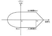
バッテリ50は、バッテリ用電子制御ユニット(以下、バッテリECUという)52によって管理されている。バッテリECU52には、バッテリ50を管理するのに必要な信号、例えば、バッテリ50の端子間に設置された図示しない電圧センサからの端子間電圧,バッテリ50の出力端子に接続された電力ライン54に取り付けられた図示しない電流センサからの充放電電流,バッテリ50に取り付けられた温度センサ51からの電池温度Tbなどが入力されており、必要に応じてバッテリ50の状態に関するデータを通信によりハイブリッド用電子制御ユニット70に出力する。また、バッテリECU52は、バッテリ50を管理するために電流センサにより検出された充放電電流の積算値に基づいて残容量(SOC)を演算したり、演算した残容量(SOC)と電池温度Tbとに基づいてバッテリ50を充放電してもよい最大許容電力である入出力制限Win,Woutを演算している。なお、バッテリ50の入出力制限Win,Woutは、電池温度Tbに基づいて入出力制限Win,Woutの基本値を設定し、バッテリ50の残容量(SOC)に基づいて出力制限用補正係数と入力制限用補正係数とを設定し、設定した入出力制限Win,Woutの基本値に補正係数を乗じることにより設定することができる。図2に電池温度Tbと入出力制限Win,Woutとの関係の一例を示し、図3にバッテリ50の残容量(SOC)と入出力制限Win,Woutの補正係数との関係の一例を示す。入力制限Winは、図2において、バッテリ温度Tbが0℃からT1℃(例えば、40℃,41℃,42℃など)の通常の温度範囲にあるときには最小値Wimin(例えば。−21kw,−20kw,−19kwなど)となり、バッテリ温度Tbが0℃以下であるときやT1℃以上であるときには最小値Wiminから徐々に大きくなるよう設定するものとした。
The
ハイブリッド用電子制御ユニット70は、CPU72を中心とするマイクロプロセッサとして構成されており、CPU72の他に処理プログラムを記憶するROM74と、データを一時的に記憶するRAM76と、図示しない入出力ポートおよび通信ポートとを備える。ハイブリッド用電子制御ユニット70には、イグニッションスイッチ80からのイグニッション信号,シフトレバー81の操作位置を検出するシフトポジションセンサ82からのシフトポジションSP,アクセルペダル83の踏み込み量を検出するアクセルペダルポジションセンサ84からのアクセル開度Acc,ブレーキペダル85の踏み込み量を検出するブレーキペダルポジションセンサ86からのブレーキペダルポジションBP,車速センサ88からの車速V,運転席近傍に取り付けられて車両の燃費を優先する旨が指示されたときにオンされるエコスイッチ89からのエコスイッチ信号ESWなどが入力ポートを介して入力されている。ハイブリッド用電子制御ユニット70は、前述したように、エンジンECU24やモータECU40,バッテリECU52と通信ポートを介して接続されており、エンジンECU24やモータECU40,バッテリECU52と各種制御信号やデータのやりとりを行なっている。なお、シフトポジションSPとしては、通常の前進走行用のドライブポジション(Dポジション)、アクセルオフ時の制動力が大きな前進走行用のブレーキポジション(Bポジション)、後進走行用のリバースポジション(Rポジション)、中立のニュートラルポジション(Nポジション)、駐車時に用いる駐車ポジション(Pポジション)などがある。
The hybrid
こうして構成された実施例のハイブリッド自動車20は、運転者によるアクセルペダル83の踏み込み量に対応するアクセル開度Accと車速Vとに基づいて駆動軸としてのリングギヤ軸32aに出力すべき要求トルクを計算し、この要求トルクに対応する要求動力がリングギヤ軸32aに出力されるように、エンジン22とモータMG1とモータMG2とが運転制御される。エンジン22とモータMG1とモータMG2の運転制御としては、要求動力に見合う動力がエンジン22から出力されるようにエンジン22を運転制御すると共にエンジン22から出力される動力のすべてが動力分配統合機構30とモータMG1とモータMG2とによってトルク変換されてリングギヤ軸32aに出力されるようモータMG1およびモータMG2を駆動制御するトルク変換運転モードや要求動力とバッテリ50の充放電に必要な電力との和に見合う動力がエンジン22から出力されるようにエンジン22を運転制御すると共にバッテリ50の充放電を伴ってエンジン22から出力される動力の全部またはその一部が動力分配統合機構30とモータMG1とモータMG2とによるトルク変換を伴って要求動力がリングギヤ軸32aに出力されるようモータMG1およびモータMG2を駆動制御する充放電運転モード、エンジン22の運転を停止してモータMG2からの要求動力に見合う動力をリングギヤ軸32aに出力するよう運転制御するモータ運転モードなどがある。
The
次に、こうして構成された実施例のハイブリッド自動車20の動作、特に、アクセルペダル83がオフ(アクセル開度Accが0%)された状態で前進走行している際の動作について説明する。図4はハイブリッド用電子制御ユニット70により実行されるアクセルオフ時駆動制御ルーチンの一例を示すフローチャートである。このルーチンは、アクセルペダル83がオフされるとともにシフトポジションSPが前進走行用のシフトポジションであるDポジションまたはBポジションである状態で、駆動軸としてのリングギヤ軸32aに要求されるトルクである後述する要求トルクTr*が負の値に設定される車速の下限、つまり、駆動時に制動トルクが要求される車速の下限として予め設定された所定車速Vmin(シフトポジションがDポジションのときには値V1(例えば、10km/h,11km/h,12km/hなど),シフトポジションSPがBポジションのときには値V2(例えば、8km/h,9km/h,10km/hなど))を車速Vが超えているときに、所定時間毎(例えば数msec毎)に繰り返し実行される。
Next, the operation of the
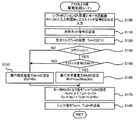
アクセルオフ時駆動制御ルーチンが実行されると、ハイブリッド用電子制御ユニット70のCPU72は、まず、車速センサ88からの車速V,エコスイッチ89からのエコスイッチ信号ESW,シフトポジションセンサ82からのシフトポジションSP,モータMG1,MG2の回転数Nm1,Nm2,バッテリ50の入力制限Winなど制御に必要なデータを入力する処理を実行する(ステップS100)。ここで、モータMG1,MG2の回転数Nm1,Nm2は、回転位置検出センサ43,44により検出されたモータMG1,MG2の回転子の回転位置に基づいて演算されたものをモータECU40から通信により入力するものとした。また、バッテリ50の入力制限Winは、バッテリ50の電池温度Tbとバッテリ50の残容量(SOC)とに基づいて設定されたものをバッテリECU52から通信により入力するものとした。
When the accelerator-off drive control routine is executed, the
こうしてデータを入力すると、エンジン22の燃料噴射を停止するための燃料カット指令をエンジンECU24に送信する(ステップS110)。燃料カット指令を受信したエンジンECU24は、燃料噴射制御や点火制御を停止する処理を実行する。
When the data is input in this way, a fuel cut command for stopping the fuel injection of the
続いて、シフトポジションSPと車速Vに基づいて車両に要求されるトルクとして駆動輪63a,63bに連結された駆動軸としてのリングギヤ軸32aに出力すべき要求トルクTr*を設定する(ステップS120)。要求トルクTr*は、実施例では、アクセル開度Accが0%であるときの車速Vと要求トルクTr*とシフトポジションSPとの関係を予め定めてアクセルオフ時要求トルク設定用マップとしてROM74に記憶しておき、車速VとシフトポジションSPとが与えられると記憶したマップから対応する要求トルクTr*を導出して設定するものとした。図5にアクセルオフ時要求トルク設定用マップの一例を示す。要求トルクTr*は、図示するように、車速Vが下限車速Vmin(シフトポジションSPがDポジションのときには値V1,シフトポジションSPがBポジションのときには値V2)以上であるときに負の値、すなわち、制動トルクとして設定されるシフトポジションSPがBポジションであるときの要求トルクTr*は、シフトポジションSPがDポジションであるときに比して小さくなるよう(絶対値としては大きくなるよう)設定することができる。
Subsequently, based on the shift position SP and the vehicle speed V, the required torque Tr * to be output to the ring gear shaft 32a as the drive shaft connected to the
続いて、シフトポジションSPを調べて(ステップS130)、シフトポジションSPがDポジションであるときには、ステップS100の処理で入力された入力制限Winを実行用充電電力Winfとして設定して(ステップS150)、次式(1)および次式(2)を共に満たすようモータMG1,MG2のトルク指令Tm1*,Tm2*を設定する(ステップS170)。式(1)はモータMG1やモータMG2によりリングギヤ軸32aに出力されるトルクの総和が要求トルクTr*となる関係式であり、式(2)はモータMG1とモータMG2とにより入出力される電力の総和が実行用充電電力Winfとなる関係式である。図6はエンジン22からパワーを出力していない状態で走行しているときの動力分配統合機構30の回転要素における回転数とトルクとの力学的な関係を示す共線図である。図6では、左のS軸はモータMG1の回転数Nm1であるサンギヤ31の回転数を示し、C軸はエンジン22の回転数Neであるキャリア34の回転数を示し、R軸はモータMG2の回転数Nm2を減速ギヤ35のギヤ比Grで除したリングギヤ32の回転数Nrを示す。式(1)は、この共線図を用いれば容易に導くことができる。なお、R軸上の2つの太線矢印は、モータMG1から出力されたトルクTm1がリングギヤ軸32aに作用するトルクと、モータMG2から出力されるトルクTm2が減速ギヤ35を介してリングギヤ軸32aに作用するトルクとを示す。式(2)において、入力制限Winを実行用充電電力Winfとして設定して、モータMG1とモータMG2とにより入出力される電力の総和が実行用充電電力Winfになるようトルク指令Tm1*,Tm2*を設定するのは、モータMG2の回生制御によりバッテリ50を充電する電力をなるべく大きくして車両全体のエネルギ効率の向上を図るためである。こうしてモータMG1,MG2のトルク指令Tm1*,Tm2*を設定することにより、モータMG2の回生制御によりバッテリ50を充電する電力をなるべく大きくする電力で充電することができ、車両のエネルギ効率の向上を図ることができる。
Subsequently, the shift position SP is checked (step S130). When the shift position SP is the D position, the input restriction Win input in the process of step S100 is set as the execution charging power Winf (step S150). Torque commands Tm1 * and Tm2 * for motors MG1 and MG2 are set so as to satisfy both the following expressions (1) and (2) (step S170). Expression (1) is a relational expression in which the sum of torques output to the ring gear shaft 32a by the motor MG1 and the motor MG2 is the required torque Tr *, and Expression (2) is the electric power input / output by the motor MG1 and the motor MG2. Is a relational expression in which the charging power for execution Winf is obtained. FIG. 6 is a collinear diagram showing the dynamic relationship between the rotational speed and torque in the rotating elements of the power distribution and
−Tm1*/ρ+Tm2*・Gr=Tr* (1)
Tm1*・Nm1+Tm2*・Nm2=Winf (2)
−Tm1 * / ρ + Tm2 * ・ Gr = Tr * (1)
Tm1 * ・ Nm1 + Tm2 * ・ Nm2 = Winf (2)
こうしてモータMG1,MG2のトルク指令Tm1*,Tm2*を設定すると、設定したトルク指令Tm1*,Tm2*をモータECU40に送信し(ステップS180)、アクセルオフ時駆動制御ルーチンを終了する。トルク指令Tm1*,Tm2*を受信したモータECU40は、トルク指令Tm1*でモータMG1が駆動されると共にトルク指令Tm2*でモータMG2が駆動されるようインバータ41,42のスイッチング素子のスイッチング制御を行なう。こうした制御により、アクセルペダル83がオフされていると共にシフトポジションがDポジションであるときには、エンジン22における燃料噴射制御を停止した状態で駆動軸としてのリングギヤ軸32aに制動トルクとしての要求トルクTr*を出力して走行することができる。このとき、入力制限Winに設定された実行用充電電力Winfでバッテリ50を充電することができるから、車両のエネルギ効率の向上を図ることができる。
When the torque commands Tm1 * and Tm2 * for the motors MG1 and MG2 are set in this way, the set torque commands Tm1 * and Tm2 * are transmitted to the motor ECU 40 (step S180), and the accelerator-off drive control routine is terminated. Receiving the torque commands Tm1 * and Tm2 *, the motor ECU 40 controls the switching elements of the
シフトポジションSPがBポジションであるときには(ステップS130)、続いて、エコスイッチ信号ESWを調べる(ステップS140)。エコスイッチ信号ESWがオフであるとき、すなわち、燃費優先走行が指示されていないときには、ステップS100の処理で入力された入力制限Winと予め定められたBポジション時充電電力Winbとのうち大きいほうの電力を実行用充電電力Winfとして設定し(ステップS160)、上述した式(1)および式(2)を共に満たすようモータMG1のトルク指令Tm1*,Tm2*を設定すると共に設定したトルク指令Tm1*,Tm2*をモータECU40に送信して(ステップS170,S180)、アクセルオフ時駆動制御ルーチンを終了する。ステップS160の処理で、Bポジション時充電電力Winbは、バッテリ温度Tbが通常の温度範囲である0℃からT1℃であるときの入力制限Winの最小値Wiminより大きく(絶対値としては小さく)比較的値0に近い電力として、例えば、−3kW,−5kW,−7kWなどに設定されるものとした。ここで、入力制限WinとBポジション用入力制限Winbとのうち大きいほうを実行用充電電力Winfとして設定する理由について説明する。図7は、上述した式(1)および式(2)を用いてモータMG1のトルク指令Tm1*,Tm2*を設定する様子の一例を示す説明図である。図中、実線は式(2)中の実行用充電電力WinfにBポジション用入力制限Winbを設定した場合の関係を示しており、破線は式(2)中の実行用充電電力Winfに最小値Wiminを設定した場合の関係を示している。トルク指令Tm1*,Tm2*は、図示するように、式(2)の関係上で式(1)を満たすトルクとして設定されるから、実行用充電電力WinfにBポジション用入力制限Winbを設定すると、実行用充電電力Winfに最小値Wiminを設定した場合に比して負の値であるトルク指令Tm2*が大きくなるためモータMG2の回生制御によりバッテリ50に充電される電力が小さくなり、正の値であるトルク指令Tm1*が大きくなるためエンジン22の回転数Neがより高くなってエンジン22の回転抵抗で車両に作用する制動力が大きくなる。このように、負の値である実行用充電電力Winfを値0に近くなるよう大きくすることにより、モータMG2の回生制御によりバッテリ50に充電される電力を小さくすると共にエンジン22の回転抵抗で車両に作用する制動力を大きくすることができ、アクセルオフ時に運転者に良好なフィーリングを与えることができる。こうした理由により、入力制限WinとBポジション用入力制限Winbとのうち大きいほうを実行用充電電力Winfとして設定するのである。このように、シフトポジションSPがBポジションであると共にエコスイッチ信号ESWがオフであるときには、入力制限WinとBポジション用入力制限Winbとのうち大きいほうを実行用充電電力Winfとして設定して実行用充電電力Winfでバッテリ50が充電されると共に要求トルクTr*で走行するようモータMG1,MG2を制御するから、シフトポジションSPがDポジションである場合に比してモータMG2の回生制御によるバッテリ50の充電を抑制しながらエンジン22の回転抵抗による制動力がリングギヤ軸32aに作用するのを促進させることができ、アクセルオフ時に運転者に良好なフィーリングを与えることができる。
When the shift position SP is the B position (step S130), the eco switch signal ESW is subsequently checked (step S140). When the eco switch signal ESW is off, that is, when fuel efficiency priority driving is not instructed, the larger one of the input limit Win input in the process of step S100 and the predetermined B-position charge power Winb. The power is set as the execution charging power Winf (step S160), and the torque commands Tm1 * and Tm2 * of the motor MG1 are set and the set torque command Tm1 * so as to satisfy both the above formulas (1) and (2). , Tm2 * are transmitted to the motor ECU 40 (steps S170 and S180), and the accelerator-off-time drive control routine is terminated. In the process of step S160, the charging power Winb at the B position is larger (smaller as an absolute value) than the minimum value Wimin of the input limit Win when the battery temperature Tb is 0 ° C. to T1 ° C. which is a normal temperature range. For example, the power close to the
エコスイッチ信号ESWがオンであるとき、すなわち、燃費優先走行が指示されているときには(ステップS140)、実行用充電電力WinfにステップS100の処理で入力された入力制限Winを設定して(ステップS150)、上述した式(1)および式(2)を共に満たすようモータMG1,MG2のトルク指令Tm1*,Tm2*を設定すると共に設定したトルク指令Tm1*,Tm2*をモータECU40に送信して(ステップS170,S180)、アクセルオフ時駆動制御ルーチンを終了する。このように、シフトポジションSPがBポジションであると共にエコスイッチ信号ESWがオンであるときには、入力制限Winを実行用充電電力Winfとして設定して実行用充電電力Winfでバッテリ50が充電されると共に要求トルクTr*で走行するようモータMG1,MG2を制御するから、シフトポジションSPがBポジションであると共にエコスイッチ信号ESWがオフであるときに比して、モータMG2の回生制御によりバッテリ50に充電される電力を大きくすることができ、車両全体のエネルギ効率の向上を図ることができる。
When the eco switch signal ESW is on, that is, when fuel efficiency priority running is instructed (step S140), the input restriction Win input in the process of step S100 is set to the execution charging power Winf (step S150). ), Torque commands Tm1 * and Tm2 * of the motors MG1 and MG2 are set so as to satisfy both the above-described equations (1) and (2), and the set torque commands Tm1 * and Tm2 * are transmitted to the motor ECU 40 ( Steps S170 and S180), the accelerator-off drive control routine is terminated. Thus, when the shift position SP is the B position and the eco switch signal ESW is on, the input limit Win is set as the execution charge power Winf, and the
以上説明した実施例のハイブリッド自動車20によれば、アクセルペダル83がオフされた状態でシフトポジションSPがBポジションであるとき、エコスイッチ信号ESWがオフであるときには、入力制限WinとBポジション用入力制限Winbとのうち大きいほうを実行用充電電力Winfとして設定して実行用充電電力Winfでバッテリ50が充電されると共に要求トルクTr*で走行するようモータMG1,MG2を制御することにより、シフトポジションSPがDポジションである場合に比してモータMG2の回生制御によるバッテリ50の充電を抑制しながらエンジン22の回転抵抗による制動力をリングギヤ軸32aに作用するのを促進させることができ、アクセルオフ時に運転者に良好なフィーリングを与えることができる。そして、エコスイッチ信号ESWがオンであるときには、入力制限Winを実行用充電電力Winfとして設定して実行用充電電力Winfでバッテリ50が充電されると共に要求トルクTr*で走行するようモータMG1,MG2を制御することにより、シフトポジションSPがBポジションであると共にエコスイッチ信号ESWがオフであるときに比して、モータMG2の回生制御によりバッテリ50に充電される電力を大きくすることができ、車両全体のエネルギ効率の向上を図ることができる。さらに、シフトポジションSPがDポジションであるときには、エコスイッチ信号ESWに拘わらず、入力制限Winを実行用充電電力Winfとして設定して実行用充電電力Winfでバッテリ50が充電されると共に要求トルクTr*で走行するようモータMG1,MG2を制御することにより、モータMG2の回生制御によりバッテリ50に充電される電力を大きくすることができ、車両全体のエネルギ効率の向上を図ることができる。
According to the
実施例のハイブリッド自動車20では、前進走行用のシフトポジションとして、通常の前進走行用のDポジションとアクセルオフ時の制動力が大きな前進走行用のBポジションとを備えるものとしたが、Bポジションに代えて車速Vに対するエンジン22の回転数の比を例えば6段階(S1〜S6)に変更することが可能となるシーケンシャルシフトポジション(Sポジション)を備えるものとしてもよい。この場合、ステップS120の処理では、図8に示す変形例のアクセルオフ時要求トルク設定用マップを用いてシフトポジションSPと車速Vとに基づいて要求トルクTr*を設定するものとして、要求トルクTr*を車速Vが大きいほど小さくなる(制動力として大きくなる)傾向に、且つシフトポジションSPがS6からS1へ小さくなるほど小さくなる(制動力として大きくなる)傾向に定められるものにすることができる。
In the
実施例のハイブリッド自動車20では、モータMG2の動力を減速ギヤ35により変速してリングギヤ軸32aに出力するものとしたが、図9の変形例のハイブリッド自動車120に例示するように、モータMG2の動力をリングギヤ軸32aが接続された車軸(駆動輪63a,63bが接続された車軸)とは異なる車軸(図9における車輪64a,64bに接続された車軸)に接続するものとしてもよい。
In the
また、こうしたハイブリッド自動車に適用するものに限定されるものではなく、自動車以外の列車などの車両の形態としても構わない。さらに、こうした車両の制御方法の形態としてもよい。 Moreover, it is not limited to what is applied to such a hybrid vehicle, It does not matter as forms of vehicles, such as a train other than a motor vehicle. Furthermore, it is good also as a form of the control method of such a vehicle.
ここで、実施例の主要な要素と課題を解決するための手段の欄に記載した発明の主要な要素との対応関係について説明する。実施例では、エンジン22が「内燃機関」に相当し、モータMG1が「発電機」に相当し、動力分配統合機構30が「3軸式動力入出力手段」に相当し、モータMG2が「電動機」に相当し、バッテリ50が「蓄電手段」に相当し、エコスイッチ89が「燃費優先指示スイッチ」に相当し、演算した残容量(SOC)と電池温度Tbとに基づいてバッテリ50を充電してもよい最大許容電力である入力制限Winを演算するバッテリECU52が「入力制限設定手段」に相当し、アクセルペダル83がオフされた状態でシフトポジションSPがBポジションであるとき、燃料カット指令をエンジンECU24に送信する図4のアクセルオフ時駆動制御ルーチンのステップS110の処理やエコスイッチ信号ESWがオフであるときには入力制限WinとBポジション用入力制限Winbとのうち大きいほうを実行用充電電力Winfとして設定して実行用充電電力Winfでバッテリ50が充電されると共に要求トルクTr*で走行するようモータMG1,MG2のトルク指令Tm1*,Tm2*を設定してモータECU40に送信するステップS130,S140,S160〜S180の処理,エコスイッチ信号ESWがオンであるときには入力制限Winを実行用充電電力Winfとして設定して実行用充電電力Winfでバッテリ50が充電されると共に要求トルクTr*で走行するようモータMG1,MG2のトルク指令Tm1*,Tm2*を設定してモータECU40に送信するステップS130〜S150,S170,S180の処理を実行するハイブリッド用電子制御ユニット70と燃料カット指令を受信してエンジン22における燃料噴射制御や点火制御を停止する処理を実行するエンジンECU24とトルク指令Tm1*,Tm2*に基づいてモータMG1,MG2を制御するモータECU40とが「制御手段」に相当する。
Here, the correspondence between the main elements of the embodiment and the main elements of the invention described in the column of means for solving the problems will be described. In the embodiment, the
ここで、「内燃機関」としては、ガソリンまたは軽油などの炭化水素系の燃料により動力を出力する内燃機関に限定されるものではなく、水素エンジンなど如何なるタイプの内燃機関であっても構わない。「発電機」としては、同期発電電動機として構成されたモータMG1に限定されるものではなく、誘導電動機など、動力を入出力可能なものであれば如何なるタイプの電動機であっても構わない。「3軸式動力入出力手段」としては、上述の動力分配統合機構30に限定されるものではなく、ダブルピニオン式の遊星歯車機構を用いるものや複数の遊星歯車機構を組み合わせたものやデファレンシャルギヤのように遊星歯車とは異なる差動作用を有するものなど、車軸に連結された駆動軸と前記内燃機関の出力軸と前記発電機の回転軸との3軸に接続され、該3軸のうちのいずれか2軸に入出力される動力に基づいて残余の軸に動力を入出力するものであれば如何なるものとしても構わない。「電動機」としては、同期発電電動機として構成されたモータMG2に限定されるものではなく、誘導電動機など、駆動軸に動力を入出力可能なものであれば如何なるタイプの電動機であっても構わない。「蓄電手段」としては、二次電池としてのバッテリ50に限定されるものではなく、キャパシタなど、発電機および電動機と電力のやりとりが可能であれば如何なるものとしても構わない。「燃費優先指示スイッチ」としては、エコスイッチ89に限定されるものではなく、燃費優先を指示するものであれば如何なるものとしても構わない。「制御手段」としては、ハイブリッド用電子制御ユニット70とエンジンECU24とモータECU40とからなる組み合わせに限定されるものではなく単一の電子制御ユニットにより構成されるなどとしてもよい。また、「制御手段」としては、アクセルペダル83がオフされた状態でシフトポジションSPがBポジションであるとき、エンジン22における燃料噴射制御や点火制御を停止すると共に、エコスイッチ信号ESWがオフであるときには入力制限WinとBポジション用入力制限Winbとのうち大きいほうを実行用充電電力Winfとして設定して実行用充電電力Winfでバッテリ50が充電されると共に要求トルクTr*で走行するようモータMG1,MG2のトルク指令Tm1*,Tm2*を設定してモータMG1,MG2を制御し、エコスイッチ信号ESWがオンであるときには入力制限Winを実行用充電電力Winfとして設定して実行用充電電力Winfでバッテリ50が充電されると共に要求トルクTr*で走行するようモータMG1,MG2のトルク指令Tm1*,Tm2*を設定してモータMG1,MG2を制御するものに限定されるものではなく、アクセルオフ時であると共にシフトポジションが通常の走行用ポジションよりもアクセルオフ時に大きな制動力が要求される制動用ポジションにあるとき、燃費優先指示スイッチにより燃費優先が指示されていないときには蓄電手段が通常の状態であるときに予め定められた所定電力を設定された入力制限で制限した電力で蓄電手段を充電しながら内燃機関における燃料噴射制御を停止した状態で走行に要求される要求制動力により走行するよう内燃機関と発電機と電動機とを制御し、燃費優先指示スイッチにより燃費優先が指示されているときには設定された入力制限で蓄電手段を充電しながら燃料噴射制御を停止した状態で要求制動力により走行するよう内燃機関と発電機と電動機とを制御するものであれば如何なるものとしても構わない。
Here, the “internal combustion engine” is not limited to an internal combustion engine that outputs power using a hydrocarbon fuel such as gasoline or light oil, and may be any type of internal combustion engine such as a hydrogen engine. The “generator” is not limited to the motor MG1 configured as a synchronous generator motor, and may be any type of motor as long as it can input and output power, such as an induction motor. The “three-axis power input / output means” is not limited to the power distribution and
なお、実施例の主要な要素と課題を解決するための手段の欄に記載した発明の主要な要素との対応関係は、実施例が課題を解決するための手段の欄に記載した発明を実施するための最良の形態を具体的に説明するための一例であることから、課題を解決するための手段の欄に記載した発明の要素を限定するものではない。即ち、課題を解決するための手段の欄に記載した発明についての解釈はその欄の記載に基づいて行なわれるべきものであり、実施例は課題を解決するための手段の欄に記載した発明の具体的な一例に過ぎないものである。 The correspondence between the main elements of the embodiment and the main elements of the invention described in the column of means for solving the problem is the same as that of the embodiment described in the column of means for solving the problem. It is an example for specifically explaining the best mode for doing so, and does not limit the elements of the invention described in the column of means for solving the problem. That is, the interpretation of the invention described in the column of means for solving the problems should be made based on the description of the column, and the examples are those of the invention described in the column of means for solving the problems. It is only a specific example.
以上、本発明を実施するための最良の形態について実施例を用いて説明したが、本発明はこうした実施例に何等限定されるものではなく、本発明の要旨を逸脱しない範囲内において、種々なる形態で実施し得ることは勿論である。 The best mode for carrying out the present invention has been described with reference to the embodiments. However, the present invention is not limited to these embodiments, and various modifications can be made without departing from the gist of the present invention. Of course, it can be implemented in the form.
本発明は、車両の製造産業などに利用可能である。 The present invention can be used in the vehicle manufacturing industry.
20,120 ハイブリッド自動車、22 エンジン、24 エンジン用電子制御ユニット(エンジンECU)、26 クランクシャフト、28 ダンパ、30 動力分配統合機構、31 サンギヤ、32 リングギヤ、32a リングギヤ軸、33 ピニオンギヤ、34 キャリア、35 減速ギヤ、40 モータ用電子制御ユニット(モータECU)、41,42 インバータ、43,44 回転位置検出センサ、50 バッテリ、51 温度センサ、52 バッテリ用電子制御ユニット(バッテリECU)、54 電力ライン、60 ギヤ機構、62 デファレンシャルギヤ、63a,63b 駆動輪、64a,64b 車輪、70 ハイブリッド用電子制御ユニット、72 CPU、74 ROM、76 RAM、80 イグニッションスイッチ、81 シフトレバー、82 シフトポジションセンサ、83 アクセルペダル、84 アクセルペダルポジションセンサ、85 ブレーキペダル、86 ブレーキペダルポジションセンサ、88 車速センサ、89 エコスイッチ、MG1,MG2 モータ。 20, 120 Hybrid vehicle, 22 engine, 24 electronic control unit (engine ECU) for engine, 26 crankshaft, 28 damper, 30 power distribution integration mechanism, 31 sun gear, 32 ring gear, 32a ring gear shaft, 33 pinion gear, 34 carrier, 35 Reduction gear, 40 Motor electronic control unit (motor ECU), 41, 42 Inverter, 43, 44 Rotation position detection sensor, 50 battery, 51 Temperature sensor, 52 Battery electronic control unit (battery ECU), 54 Power line, 60 Gear mechanism, 62 differential gear, 63a, 63b drive wheel, 64a, 64b wheel, 70 hybrid electronic control unit, 72 CPU, 74 ROM, 76 RAM, 80 ignition switch, 81 Shift lever, 82 shift position sensor, 83 accelerator pedal, 84 accelerator pedal position sensor, 85 brake pedal, 86 brake pedal position sensor, 88 vehicle speed sensor, 89 eco switch, MG1, MG2 motor.
Claims (4)
動力を入出力可能な発電機と、
車軸に連結された駆動軸と前記内燃機関の出力軸と前記発電機の回転軸との3軸に接続され、該3軸のうちのいずれか2軸に入出力される動力に基づいて残余の軸に動力を入出力する3軸式動力入出力手段と、
前記駆動軸に動力を入出力可能な電動機と、
前記発電機および前記電動機と電力のやりとりが可能な蓄電手段と、
燃費優先を指示する燃費優先指示スイッチと、
前記蓄電手段の状態に基づいて前記蓄電手段を充電する際の最大許容電力としての入力制限を設定する入力制限設定手段と、
アクセルオフ時であると共にシフトポジションが通常の走行用ポジションよりもアクセルオフ時に大きな制動力が要求される制動用ポジションにあるとき、前記燃費優先指示スイッチにより燃費優先が指示されていないときには予め定められた所定電力を前記設定された入力制限で制限した電力で前記蓄電手段を充電しながら前記内燃機関における燃料噴射制御を停止した状態で前記シフトポジションが制動用ポジションにあるときに走行に要求される要求制動力により走行するよう前記内燃機関と前記発電機と前記電動機とを制御し、前記燃費優先指示スイッチにより燃費優先が指示されているときには前記設定された入力制限で前記蓄電手段を充電しながら前記燃料噴射制御を停止した状態で前記シフトポジションが制動用ポジションにあるときに走行に要求される要求制動力により走行するよう前記内燃機関と前記発電機と前記電動機とを制御する制御手段と、
を備える車両。 An internal combustion engine;
A generator capable of inputting and outputting power;
It is connected to three shafts, that is, a drive shaft coupled to an axle, an output shaft of the internal combustion engine, and a rotating shaft of the generator, and the remaining power is determined based on power input / output to / from any two of the three shafts. 3-axis power input / output means for inputting / outputting power to the shaft;
An electric motor capable of inputting and outputting power to the drive shaft;
Power storage means capable of exchanging electric power with the generator and the motor;
A fuel efficiency priority instruction switch for instructing fuel efficiency priority;
An input restriction setting means for setting an input restriction as a maximum allowable power when charging the power storage means based on the state of the power storage means;
When the accelerator is off and the shift position is at a braking position where a greater braking force is required when the accelerator is off than the normal driving position, fuel efficiency priority is not instructed by the fuel efficiency priority instruction switch. When the shift position is at the braking position in a state where the fuel injection control in the internal combustion engine is stopped while charging the power storage means with the electric power limited by the set input restriction, the required power is required for traveling. The internal combustion engine, the generator, and the motor are controlled so as to travel with the required braking force, and when the fuel efficiency priority is instructed by the fuel efficiency priority instruction switch, the power storage means is charged with the set input restriction. the shift position is in the braking position while stopping the fuel injection control And control means for controlling said electric motor and said internal combustion engine and the generator to traveling by the required braking force required for running the Rutoki,
A vehicle comprising:
前記制動用ポジションは、アクセルオフ時に要求される要求制動力の大きさが異なる複数の走行ポジションから運転者によって選択されるポジションである
車両。 The vehicle according to claim 1,
The braking position is a position selected by the driver from a plurality of traveling positions having different required braking force levels required when the accelerator is off.
前記制御手段は、アクセルオフ時に前記シフトポジションが前記通常の走行用ポジションであるときには、前記燃費優先指示スイッチにより燃費優先が指示されているか否かに拘わらず前記燃料噴射制御を停止した状態で前記設定された入力制限で前記蓄電手段を充電しながら前記要求制動力により走行するよう前記内燃機関と前記発電機と前記電動機とを制御する手段である
車両。 The vehicle according to claim 1 or 2,
When the shift position is the normal driving position when the accelerator is off, the control means stops the fuel injection control regardless of whether or not fuel efficiency priority is instructed by the fuel efficiency priority instruction switch. A vehicle that controls the internal combustion engine, the generator, and the electric motor so as to travel with the required braking force while charging the power storage unit with a set input restriction.
前記蓄電手段の状態に基づいて前記蓄電手段を充電する際の最大許容電力としての入力制限を設定し、
アクセルオフ時であると共にシフトポジションが通常の走行用ポジションよりもアクセルオフ時に大きな制動力が要求される制動用ポジションにあるとき、前記燃費優先指示スイッチにより燃費優先が指示されていないときには予め定められた所定電力を前記設定された入力制限で制限した電力で前記蓄電手段を充電しながら前記内燃機関における燃料噴射制御を停止した状態で前記シフトポジションが制動用ポジションにあるときに走行に要求される要求制動力により走行するよう前記内燃機関と前記発電機と前記電動機とを制御し、前記燃費優先指示スイッチにより燃費優先が指示されているときには前記設定された入力制限で前記蓄電手段を充電しながら前記燃料噴射制御を停止した状態で前記シフトポジションが制動用ポジションにあるときに走行に要求される要求制動力により走行するよう前記内燃機関と前記発電機と前記電動機とを制御する
車両の制御方法。
An internal combustion engine, a generator capable of inputting / outputting power, a drive shaft coupled to an axle, an output shaft of the internal combustion engine, and a rotation shaft of the generator, connected to any of the three shafts 3-axis power input / output means for inputting / outputting power to / from the remaining shafts based on power input / output to / from the two shafts, an electric motor capable of inputting / outputting power to / from the drive shaft, the generator, the electric motor and electric power A vehicle control method comprising a power storage means capable of exchanging and a fuel efficiency priority instruction switch for instructing fuel efficiency priority,
Set the input limit as the maximum allowable power when charging the power storage means based on the state of the power storage means,
When the accelerator is off and the shift position is at a braking position where a greater braking force is required when the accelerator is off than the normal driving position, fuel efficiency priority is not instructed by the fuel efficiency priority instruction switch. When the shift position is at the braking position in a state where the fuel injection control in the internal combustion engine is stopped while charging the power storage means with the electric power limited by the set input restriction, the required power is required for traveling. The internal combustion engine, the generator, and the motor are controlled so as to travel with the required braking force, and when the fuel efficiency priority is instructed by the fuel efficiency priority instruction switch, the power storage means is charged with the set input restriction. the shift position is in the braking position while stopping the fuel injection control The control method for a vehicle for controlling the internal combustion engine and the generator the motor to run the request braking force required for running the Rutoki.
Priority Applications (1)
| Application Number | Priority Date | Filing Date | Title |
|---|---|---|---|
| JP2010055218A JP5387460B2 (en) | 2010-03-12 | 2010-03-12 | Vehicle and control method thereof |
Applications Claiming Priority (1)
| Application Number | Priority Date | Filing Date | Title |
|---|---|---|---|
| JP2010055218A JP5387460B2 (en) | 2010-03-12 | 2010-03-12 | Vehicle and control method thereof |
Publications (2)
| Publication Number | Publication Date |
|---|---|
| JP2011189766A JP2011189766A (en) | 2011-09-29 |
| JP5387460B2 true JP5387460B2 (en) | 2014-01-15 |
Family
ID=44795150
Family Applications (1)
| Application Number | Title | Priority Date | Filing Date |
|---|---|---|---|
| JP2010055218A Expired - Fee Related JP5387460B2 (en) | 2010-03-12 | 2010-03-12 | Vehicle and control method thereof |
Country Status (1)
| Country | Link |
|---|---|
| JP (1) | JP5387460B2 (en) |
Families Citing this family (2)
| Publication number | Priority date | Publication date | Assignee | Title |
|---|---|---|---|---|
| JP6028328B2 (en) * | 2011-12-22 | 2016-11-16 | トヨタ自動車株式会社 | Hybrid vehicle |
| JP5929656B2 (en) * | 2012-09-12 | 2016-06-08 | マツダ株式会社 | Vehicle control device |
Family Cites Families (4)
| Publication number | Priority date | Publication date | Assignee | Title |
|---|---|---|---|---|
| JP4175370B2 (en) * | 2006-01-13 | 2008-11-05 | トヨタ自動車株式会社 | Hybrid vehicle and control method thereof |
| JP2009132170A (en) * | 2007-11-28 | 2009-06-18 | Toyota Motor Corp | Vehicle and control method thereof |
| JP4973514B2 (en) * | 2008-01-16 | 2012-07-11 | トヨタ自動車株式会社 | Vehicle and control method thereof |
| JP5198147B2 (en) * | 2008-05-26 | 2013-05-15 | トヨタ自動車株式会社 | VEHICLE, ITS CONTROL METHOD AND DRIVE DEVICE |
-
2010
- 2010-03-12 JP JP2010055218A patent/JP5387460B2/en not_active Expired - Fee Related
Also Published As
| Publication number | Publication date |
|---|---|
| JP2011189766A (en) | 2011-09-29 |
Similar Documents
| Publication | Publication Date | Title |
|---|---|---|
| JP4345824B2 (en) | Vehicle and control method thereof | |
| JP5742568B2 (en) | Hybrid car | |
| JP4229105B2 (en) | Hybrid vehicle and control method thereof | |
| JP2009126257A (en) | Vehicle and its control method | |
| JP5200924B2 (en) | Hybrid vehicle and control method thereof | |
| JP4466635B2 (en) | POWER OUTPUT DEVICE, ITS CONTROL METHOD, AND VEHICLE | |
| JP4297108B2 (en) | Vehicle and control method thereof | |
| JP5682639B2 (en) | Hybrid car | |
| JP4692498B2 (en) | Vehicle and control method thereof | |
| JP4365354B2 (en) | Power output apparatus, automobile equipped with the same, and control method of power output apparatus | |
| JP2010195255A (en) | Hybrid vehicle and control method thereof | |
| JP2006321458A (en) | Power output device, vehicle mounted with the same, and control method therefor | |
| JP2011188569A (en) | Vehicle, and control method therefor | |
| JP4458100B2 (en) | Hybrid vehicle and control method thereof | |
| JP4345765B2 (en) | Vehicle and control method thereof | |
| JP5387460B2 (en) | Vehicle and control method thereof | |
| JP2009149154A (en) | Vehicle and control method therefor | |
| JP2009220790A (en) | Vehicle and method of controlling the same | |
| JP2009196472A (en) | Hybrid vehicle and its control method | |
| JP2008184065A (en) | Vehicle and control method thereof | |
| JP4957267B2 (en) | Power output apparatus, automobile equipped with the same, and control method of power output apparatus | |
| JP4301252B2 (en) | POWER OUTPUT DEVICE, ITS CONTROL METHOD, AND VEHICLE | |
| JP2009184387A (en) | Hybrid vehicle and method of controlling the same | |
| JP4977055B2 (en) | POWER OUTPUT DEVICE, ITS CONTROL METHOD, AND VEHICLE | |
| JP2009023527A (en) | Vehicle and control method thereof |
Legal Events
| Date | Code | Title | Description |
|---|---|---|---|
| A621 | Written request for application examination |
Free format text: JAPANESE INTERMEDIATE CODE: A621 Effective date: 20120416 |
|
| A977 | Report on retrieval |
Free format text: JAPANESE INTERMEDIATE CODE: A971007 Effective date: 20130527 |
|
| A131 | Notification of reasons for refusal |
Free format text: JAPANESE INTERMEDIATE CODE: A131 Effective date: 20130604 |
|
| A521 | Request for written amendment filed |
Free format text: JAPANESE INTERMEDIATE CODE: A523 Effective date: 20130722 |
|
| TRDD | Decision of grant or rejection written | ||
| A01 | Written decision to grant a patent or to grant a registration (utility model) |
Free format text: JAPANESE INTERMEDIATE CODE: A01 Effective date: 20130910 |
|
| A61 | First payment of annual fees (during grant procedure) |
Free format text: JAPANESE INTERMEDIATE CODE: A61 Effective date: 20130923 |
|
| R151 | Written notification of patent or utility model registration |
Ref document number: 5387460 Country of ref document: JP Free format text: JAPANESE INTERMEDIATE CODE: R151 |
|
| LAPS | Cancellation because of no payment of annual fees |