JP5929656B2 - Vehicle control device - Google Patents
Vehicle control device Download PDFInfo
- Publication number
- JP5929656B2 JP5929656B2 JP2012200057A JP2012200057A JP5929656B2 JP 5929656 B2 JP5929656 B2 JP 5929656B2 JP 2012200057 A JP2012200057 A JP 2012200057A JP 2012200057 A JP2012200057 A JP 2012200057A JP 5929656 B2 JP5929656 B2 JP 5929656B2
- Authority
- JP
- Japan
- Prior art keywords
- vehicle
- range
- level
- braking force
- regenerative braking
- Prior art date
- Legal status (The legal status is an assumption and is not a legal conclusion. Google has not performed a legal analysis and makes no representation as to the accuracy of the status listed.)
- Expired - Fee Related
Links
Images


Landscapes
- Electric Propulsion And Braking For Vehicles (AREA)
Description
本発明は、車両用制御装置、詳しくは、車両の加速時に電力の供給を受けて車輪を駆動する機能と、車両の減速時に回転する車輪から動力を得て発電する機能とを備えた電動機が搭載された車両を制御する車両用制御装置に関する。 The present invention relates to a vehicle control device, and more specifically, an electric motor having a function of driving a wheel by receiving power supply when the vehicle is accelerated and a function of generating power by obtaining power from a wheel that rotates when the vehicle is decelerated. The present invention relates to a vehicle control device that controls a mounted vehicle.
一般に、ハイブリッド車や電気自動車はモータジェネレータを搭載する。このモータジェネレータは、車両の加速時に電力の供給を受けて車輪を駆動する機能と、車両の減速時に回転する車輪から動力を得て発電する機能とを備えている。ここで、加速時とは、運転者が加速を要求してアクセル操作をしているとき(駆動源から車輪に動力が伝達される正駆動時)をいい、車速が増大している場合だけでなく、上り坂等で車速が増大していない場合も含まれる。また、減速時とは、運転者が減速を要求してアクセル操作をしていないとき(車輪から駆動源に動力が伝達される逆駆動時)をいい、車速が減少している場合だけでなく、下り坂等で車速が減少していない場合も含まれる。 In general, a hybrid vehicle or an electric vehicle is equipped with a motor generator. This motor generator has a function of driving a wheel by receiving power supply when the vehicle is accelerated, and a function of generating power by obtaining power from a wheel that rotates when the vehicle is decelerated. Here, “acceleration” means when the driver is accelerating the accelerator operation (during positive drive when power is transmitted from the drive source to the wheels), and only when the vehicle speed is increasing. In addition, the case where the vehicle speed does not increase due to uphill or the like is also included. The term “deceleration” refers to when the driver does not operate the accelerator to request deceleration (during reverse drive in which power is transmitted from the wheels to the drive source), and not only when the vehicle speed is decreasing. It also includes cases where the vehicle speed is not decreasing due to downhill or the like.
減速時は、モータジェネレータが発電する回生電力に呼応する大きさの回生制動力(逆トルク又は回生トルク)が得られる。回生制動力に関する技術として、例えば特許文献1には、シフトレバーのシフトポジションとして、P,R,N,D等の各レンジが配列されたメイン列と、回生制動力を調整するためのサブ列とが隣接して設けられ、シフトレバーをメイン列のDレンジからサブ列に移動させてサブ列内でMAX位置方向又はMIN位置方向にスライドさせることにより、回生制動力を運転者の意思により通常の大きさから増大又は減少することができるように構成されたハイブリッド車が開示されている。
During deceleration, regenerative braking force (reverse torque or regenerative torque) having a magnitude corresponding to the regenerative power generated by the motor generator is obtained. As a technique related to regenerative braking force, for example,
しかし、前記特許文献1に記載の技術では、回生制動力を調整しようとすると、シフトレバーをメイン列からサブ列に移動させなければならず、また、その後、レンジをDレンジから他のレンジに切り替えようとすると、シフトレバーをサブ列からメイン列に移動させなければならず、操作性に劣るという問題がある。
However, in the technique described in
そこで、本発明は、操作性よく減速時の回生制動力を調整することのできる車両用制御装置の提供を目的とする。 Accordingly, an object of the present invention is to provide a vehicle control device that can adjust the regenerative braking force during deceleration with good operability.
前記課題を解決するためのものとして、本発明は、車両の加速時に電力の供給を受けて車輪を駆動する機能と、車両の減速時に回転する車輪から動力を得て発電する機能とを備えた電動機が搭載された車両を制御する車両用制御装置であって、複数の走行レンジのうちのいずれか1つを選択するために移動操作されるシフトレバーと、前記シフトレバーに設けられ、車両の減速時に電動機が発電する回生電力を増大又は減少させるために操作されるチャージスイッチと、車両の減速時に、前記シフトレバーの移動操作で選択された走行レンジと、前記チャージスイッチの操作状態とに基いて、前記電動機から車輪に付与される回生制動力の大きさを決定し、決定した大きさの回生制動力が得られるように前記電動機を制御する制御手段とを有し、前記シフトレバーで選択可能な走行レンジとして、第1のレンジと、加速時の電動機の出力が第1のレンジよりも控えられる第2のレンジとが設けられ、前記チャージスイッチは、オン又はオフの2段階に操作されるスイッチであり、前記制御手段は、前記シフトレバーで前記第1のレンジが選択され、且つ前記チャージスイッチがオフのとき、減速時の回生制動力を第1のレベルに設定し、前記シフトレバーで前記第1のレンジが選択され、且つ前記チャージスイッチがオンのとき、減速時の回生制動力を第1のレベルよりも大きい第2のレベルに設定し、前記シフトレバーで前記第2のレンジが選択され、且つ前記チャージスイッチがオフのとき、減速時の回生制動力を第1のレベルよりも大きい第3のレベルに設定し、前記シフトレバーで前記第2のレンジが選択され、且つ前記チャージスイッチがオンのとき、減速時の回生制動力を第2のレベル及び第3のレベルよりも大きい第4のレベルに設定し、前記第2のレベルの回生制動力と前記第3のレベルの回生制動力とは相互に同一の大きさであることを特徴とする車両用制御装置である(請求項1)。 In order to solve the above-described problems, the present invention has a function of driving a wheel by receiving power supply during acceleration of the vehicle and a function of generating power by obtaining power from a wheel that rotates during deceleration of the vehicle. A control device for a vehicle that controls a vehicle on which an electric motor is mounted, the shift lever being moved to select any one of a plurality of travel ranges, the shift lever, Based on the charge switch operated to increase or decrease the regenerative power generated by the motor during deceleration, the travel range selected by the shift lever moving operation during vehicle deceleration, and the operation state of the charge switch. There are, chromatic and control means the imparted from the motor to the wheels to determine the magnitude of the regenerative braking force, and controls the electric motor as the regenerative braking force of the determined size is obtained The travel range that can be selected by the shift lever includes a first range and a second range in which the output of the motor during acceleration is lower than the first range, and the charge switch is turned on or off The control means controls the regenerative braking force during deceleration to the first level when the first range is selected by the shift lever and the charge switch is off. And when the first range is selected by the shift lever and the charge switch is on, the regenerative braking force during deceleration is set to a second level greater than the first level, and the shift lever When the second range is selected and the charge switch is OFF, the regenerative braking force during deceleration is set to a third level larger than the first level, and the shift When the second range is selected by the bar and the charge switch is on, the regenerative braking force during deceleration is set to a second level and a fourth level greater than the third level, and the second range The regenerative braking force at the second level and the regenerative braking force at the third level have the same magnitude as each other (claim 1).
本発明によれば、複数の走行レンジのうちのいずれか1つを選択するために移動操作されるシフトレバーの他に、車両の減速時に電動機が発電する回生電力を増大又は減少させるために操作されるチャージスイッチが設けられているので、運転者は、前記チャージスイッチを操作することにより、前記シフトレバーを移動操作することなく、制御手段の動作によって減速時の回生制動力を簡便に調整することができる。しかも、前記チャージスイッチは、シフトレバーに設けられているので、運転者は、シフトレバーでレンジを選択するときと同様の姿勢で回生制動力を調整することができ、回生制動力を調整する操作の負担が軽くて済む。以上により、本発明によれば、運転者は操作性よく減速時の回生制動力を調整することができる。 According to the present invention, in addition to a shift lever that is moved to select any one of a plurality of travel ranges, an operation is performed to increase or decrease the regenerative power generated by the motor when the vehicle is decelerated. Since the charge switch to be operated is provided, the driver can easily adjust the regenerative braking force during deceleration by operating the control means without operating the shift lever by operating the charge switch. be able to. Moreover, since the charge switch is provided on the shift lever, the driver can adjust the regenerative braking force in the same posture as when the range is selected with the shift lever, and an operation for adjusting the regenerative braking force. The burden of is light. As described above, according to the present invention, the driver can adjust the regenerative braking force during deceleration with good operability.
また、本発明によれば、シフトレバーで選択される第1、第2の2つのレンジと、チャージスイッチのオン又はオフとの組み合わせにより、4つの操作パターンが得られ、各操作パターンに応じて種々の回生制動力(第1〜第4のレベルの回生制動力)のいずれか1つが決定される。その場合に、加速時の電動機の出力が相対的に大きい第1のレンジでチャージスイッチがオフのときは、最も小さい第1のレベルの回生制動力が決定されるので、アクセル操作(アクセルオン)からアクセル非操作(アクセルオフ)に切り替わったときの減速度が弱めとなり、加速度の変化が小さいよりスムーズな減速走行が実現される。一方、加速時の電動機の出力が相対的に小さい第2のレンジ(すなわち経済走行が行われるレンジ)でチャージスイッチがオンのときは、最も大きい第4のレベルの回生制動力が決定されるので、アクセル操作(アクセルオン)からアクセル非操作(アクセルオフ)に切り替わった後の発電量が多めとなり、経済走行レンジにおける減速時のエネルギ回収が十分に行われる。 In addition, according to the present invention , four operation patterns are obtained by combining the first and second ranges selected by the shift lever and the on / off of the charge switch, and according to each operation pattern. Any one of various regenerative braking forces (first to fourth level regenerative braking forces) is determined. In this case, when the charge switch is off in the first range where the output of the motor during acceleration is relatively large, the smallest first level regenerative braking force is determined, so that the accelerator operation (accelerator on) is performed. When the vehicle is switched from non-accelerator operation (accelerator off), the deceleration becomes weaker, and a smoother decelerating travel with a small change in acceleration is realized. On the other hand, when the charge switch is on in the second range where the output of the motor during acceleration is relatively small (that is, the range where economic driving is performed), the largest fourth level regenerative braking force is determined. The amount of power generation after switching from the accelerator operation (accelerator on) to the accelerator non-operation (accelerator off) becomes larger, and energy recovery during deceleration in the economic travel range is sufficiently performed.
しかも、第2のレベルの回生制動力と第3のレベルの回生制動力とは相互に同一の大きさであるので、第1のレンジでチャージスイッチがオンのときと、第2のレンジでチャージスイッチがオフのときとで、得られる減速度が同じになり、第1のレベルよりも大きく、第4のレベルよりも小さい中間の減速度が2つの操作パターンのいずれを選択しても共通に得られることになる。これにより、設定可能な減速度のレベルが大、中、小の3段階になるので、運転者は現在設定されている減速度のレベルを容易に把握することができ、操作性が向上する。 In addition, since the second level regenerative braking force and the third level regenerative braking force have the same magnitude , the charge is applied when the charge switch is on in the first range and in the second range. common switch is at the time of off, Ri is the same name deceleration obtained, greater than the first level, be smaller middle of deceleration than the fourth level select one of two operation patterns Will be obtained. As a result, the level of deceleration that can be set becomes three levels of large, medium, and small, so that the driver can easily grasp the currently set deceleration level, and the operability is improved.
本発明において、好ましくは、前記制御手段は、中速域では、車速が大きいほど減速度がリニアに大きくなるように回生制動力の大きさを決定する(請求項2)。 In the present invention, preferably, the control means, in the medium speed region, the deceleration as the vehicle speed is greater determines the magnitude of the regenerative braking force to be larger linear (claim 2).
この構成によれば、使用頻度の高い中速域(例えば40〜100km/h)では、車速が大きいほど減速度がリニアに大きくなるので、車両走行性が向上する。 According to this configuration, in the medium speed range (for example, 40 to 100 km / h) that is frequently used, the deceleration increases linearly as the vehicle speed increases, so that the vehicle traveling performance is improved.
本発明において、好ましくは、前記制御手段は、ブレーキ操作量が大きいほど減速度が大きくなるように回生制動力の大きさを決定する(請求項3)。 In the present invention, preferably, the control means determines the magnitude of the regenerative braking force to the deceleration larger the brake operation amount increases (claim 3).
この構成によれば、運転者が制動力を大きくしようとしてブレーキ操作をしたときに、ブレーキ操作量が大きいほど減速度が大きくなるので、運転者は車両の性能に安心感を持って運転することができる。 According to this configuration, when the driver operates the brake to increase the braking force, the greater the amount of brake operation, the greater the deceleration, so the driver must drive with a sense of security in the vehicle performance. Can do.
本発明によれば、減速時の回生制動力を操作性よく調整することができるので、例えばハイブリッド車や電気自動車の運転中、運転者は希望する減速度を円滑、良好に得ることができる。 According to the present invention, since the regenerative braking force during deceleration can be adjusted with good operability, the driver can obtain the desired deceleration smoothly and satisfactorily, for example, while driving a hybrid vehicle or an electric vehicle.
以下、発明の実施形態を通して本発明をさらに詳しく説明する。なお、以下の実施形態では、車両がエンジンを搭載せずモータのみを搭載する電気自動車である場合について説明するが、本発明は、電気自動車に限らず、例えば、エンジンとモータとを搭載するハイブリッド車(エンジンと車輪とが常に連結され、エンジンによる走行をモータでアシストするパラレル式のハイブリッド車や、エンジンと車輪とが状況に応じて連結又は切り離され、エンジンによる走行とモータによる走行とエンジン及びモータによる走行とが可能なシリーズパラレル式のハイブリッド車や、エンジンと車輪とが常に切り離され、モータによる走行のみが可能なシリーズ式のハイブリッド車等)にも適用可能である。 Hereinafter, the present invention will be described in more detail through embodiments of the invention. In the following embodiment, a case where the vehicle is an electric vehicle that does not have an engine and that has only a motor will be described. However, the present invention is not limited to an electric vehicle, and for example, a hybrid that has an engine and a motor. Car (engine and wheels are always connected, parallel type hybrid vehicle that assists the engine with a motor, or the engine and wheels are connected or disconnected depending on the situation. The present invention can also be applied to a series parallel type hybrid vehicle that can be driven by a motor, a series type hybrid vehicle in which an engine and wheels are always separated and only a motor can run.
(1)全体構成
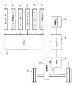
図1は、本実施形態に係る車両用制御装置のシステム構成図である。本実施形態に係る車両は、駆動源であるモータジェネレータ(図面では「MG」と略記)11と、加速時は電動機として働く前記モータジェネレータ11に電力を供給し、減速時は発電機として働く前記モータジェネレータ11で発電された電力が充電される高電圧バッテリ12とがインバータ13を介して相互に電気的に接続された電気自動車である。モータジェネレータ11は、減速機14を介して車軸15及び車輪16,16と機械的に連結されている。高電圧バッテリ12は、出力密度と容量密度とに優れるリチウムイオン電池である。
(1) Overall Configuration FIG. 1 is a system configuration diagram of a vehicle control device according to the present embodiment. The vehicle according to the present embodiment supplies electric power to a motor generator 11 (abbreviated as “MG” in the drawing) 11 as a driving source and the
モータジェネレータ11は、車輪側と連動して回転するロータと、ロータの周囲に配置されたステータとを備えている(いずれも図示省略)。ロータには、磁界を発生させるためのフィールドコイルが巻装され、ステータには、磁界を発生させるための三相コイルが巻装されている。
The
前記フィールドコイル及び三相コイルはそれぞれ個別にインバータ13に接続されている。インバータ13から三相コイルに電流が印加されると、モータジェネレータ11は、正トルクを発生する電動機として働く。一方、ロータが車輪側の回転によって強制的に回転されると、モータジェネレータ11は、電力と逆トルク(回生トルク)とを発生する発電機として働く。
The field coil and the three-phase coil are individually connected to the
モータジェネレータ11による発電時には、インバータ13からフィールドコイルに電流が印加され、それによって発生された磁界の中をロータが回転することにより、ステータの三相コイルに誘導電流が発生する。モータジェネレータ11の発電量は、フィールドコイルへの印加電流の増減によって調節される。フィールドコイルへの印加電流が高く磁束密度が高いほどモータジェネレータ11の発電量が多くなり、モータジェネレータ11による回生トルク(回生制動力)が大きくなる。
During power generation by the
運転者がアクセル操作をし、モータジェネレータ11の回転によって車輪16が回転される加速時は、モータジェネレータ11が電動機として働いて、モータジェネレータ11による駆動力(正トルク)が得られる。モータジェネレータ11の回転は、減速機14を介して車軸15及び車輪16,16に伝達され、これら15,16を回転させる。加速時は、高電圧バッテリ12からの直流電力がインバータ13によって交流電流に変換されてモータジェネレータ11に供給される。
When the driver performs an accelerator operation and the
運転者がアクセル操作をせず、車輪16の回転によってモータジェネレータ11が回転される減速時は、モータジェネレータ11が発電機として働いて、モータジェネレータ11による回生制動力(逆トルク又は回生トルク)が得られる。車軸15及び車輪16,16の回転は、減速機14を介してモータジェネレータ11に伝達され、モータジェネレータ11のロータを回転させる。減速時は、モータジェネレータ11で発電された交流電力がインバータ13によって直流電力に変換されて高電圧バッテリ12に蓄えられる。
When the driver does not operate the accelerator and the
ここで、図2(a)に示すように、本実施形態においては、車両のシフトレバー31のノブ部に、シフトボタン32とチャージスイッチ(充電スイッチ)25とが設けられている。なお、チャージスイッチ25は、ノブ部に限られず、シフトレバー31の他の部位、例えばシフトレバー31のレバー部等に設けられてもよい。
Here, as shown in FIG. 2A, in the present embodiment, a
シフトボタン32は、押圧に抗する側に常に付勢されており、押圧されることによりシフトレバー31のレンジ間の移動規制が解除され、押圧が解除されることによりシフトレバー31のレンジ間の移動が規制される。
The
チャージスイッチ25は、本実施形態では、前記シフトボタン32と同様、押しボタンの形式であり、押圧される毎に押圧が維持された状態と押圧が解除された状態とが交互に繰り返され、押圧が維持された状態ではオンとなり、押圧が解除された状態ではオフとなる。チャージスイッチ25がオンのときはオフのときに比べて減速時の回生レベルが大きくなる。つまり、インバータ13からロータのフィールドコイルに印加される電流が高くなり、モータジェネレータ11の発電量が多くなり、回生電力ひいては回生制動力が大きくなる。
In the present embodiment, the
なお、図示しないが、運転者の便宜のためにチャージスイッチ25がオンのときに点灯しオフのときに消灯する表示ランプが例えば運転席前方のインストルメントパネル等に備えられている。
Although not shown, for the convenience of the driver, a display lamp that is turned on when the
また、図2(b)に示すように、本実施形態においては、前記シフトレバー31のシフトポジションとして、P(駐車),R(後退),N(中立),D(通常走行),E(経済走行)の各レンジが一列に配列され、その配列順が表示窓34に表示されている。
Further, as shown in FIG. 2B, in this embodiment, the shift positions of the
図1に戻り、本実施形態に係る車両には、車両の走行速度(車速)を検出するための車速センサ22と、運転者のアクセル操作(アクセルペダルの踏込み)の有無及びアクセル操作量(アクセルペダルの踏込み量)を検出するためのアクセル開度センサ23と、シフトレバー31のシフトポジションを検出するためのレンジスイッチ24と、運転者の押圧操作でオン又はオフとされるチャージスイッチ25と、運転者のブレーキ操作(ブレーキペダルの踏込み)の有無を検出するためのブレーキスイッチ26と、運転者のブレーキ操作量(ブレーキペダルの踏込み量)を検出するためのブレーキ液圧センサ27とが設けられており、これらの各種センサ及びスイッチ22〜27とECU(電子制御ユニット)21とが相互に電気的に接続されている。
Returning to FIG. 1, the vehicle according to the present embodiment includes a
ECU21は、周知の通り、CPU、ROM、RAM等から構成されるマイクロプロセッサであり、本発明の制御手段に相当する。ECU21は、車両に備えられた前記各種センサ及びスイッチ22〜27から入力される種々の情報に基き、特に、減速時は、モータジェネレータ11が目標回生トルクを発生するようにインバータ13を制御する。換言すれば、ECU21は、インバータ13を介して、目標回生トルクが得られるようにモータジェネレータ11を制御する(回生制動制御)。
As is well known, the
(2)具体的制御
図3は、本実施形態に係る車両において、Dレンジ及びEレンジでの加速時のモータジェネレータ11による出力レベルと減速時のモータジェネレータ11による回生レベルとを一覧にした表である。
(2) Specific Control FIG. 3 is a table listing output levels by the
図3に示すように、加速時は、Dレンジ(第1のレンジ)では、モータジェネレータ11の出力レベルが相対的に大きくされ、モータジェネレータ11の出力(駆動力)がフル活用される(通常走行)。一方、Eレンジ(第2のレンジ)では、モータジェネレータ11の出力レベルが相対的に小さくされ、モータジェネレータ11の出力が控えめにされる(経済走行)。
As shown in FIG. 3, during acceleration, in the D range (first range), the output level of the
減速時は、Dレンジでは、モータジェネレータ11の回生レベルが相対的に小さくされ、モータジェネレータ11の発電量(回生制動力)が総じて少なくされる。一方、Eレンジでは、モータジェネレータ11の回生レベルが相対的に大きくされ、モータジェネレータ11の発電量が総じて多くされる。
At the time of deceleration, in the D range, the regeneration level of the
そして、レンジに拘らず、チャージスイッチ25がオフのとき、つまり運転者がそれほど大きい回生制動力を要求していないときは、モータジェネレータ11の回生レベルが相対的に小さくされる。一方、チャージスイッチ25がオンのとき、つまり運転者が大きい回生制動力を要求しているときは、モータジェネレータ11の回生レベルが相対的に大きくされる。
Regardless of the range, when the
その結果、本実施形態では、シフトレバー31で選択されるDレンジ、Eレンジの2つのレンジと、チャージスイッチ25のオン又はオフとの組み合わせにより、Dレンジでチャージスイッチ25がオフの第1の操作パターン、Dレンジでチャージスイッチ25がオンの第2の操作パターン、Eレンジでチャージスイッチ25がオフの第3の操作パターン、及びEレンジでチャージスイッチ25がオンの第4の操作パターンの4つの操作パターンが得られる。そして、各操作パターンに応じて複数の回生レベルのいずれか1つが決定される。その場合、第1の操作パターンの回生レベルが最も小さくされ(「小」の大きさ)、第2の操作パターンの回生レベル及び第3の操作パターンの回生レベルがそれよりも大きくされ、第4の操作パターンの回生レベルが最も大きくされている(「大」の大きさ)。そのため、第1の操作パターンの回生制動力が最も小さくされ、第2の操作パターンの回生制動力及び第3の操作パターンの回生制動力がそれよりも大きくされ、第4の操作パターンの回生制動力が最も大きくされている。
As a result, in this embodiment, the combination of the two ranges of the D range and the E range selected by the
本実施形態では、第2の操作パターンの回生レベルと第3の操作パターンの回生レベルとが相互に同一の大きさ(「中」の大きさ)とされている。そのため、第2の操作パターンの回生制動力と第3の操作パターンの回生制動力とが相互に同一の大きさとされている。 In the present embodiment, the regeneration level of the second operation pattern and the regeneration level of the third operation pattern are the same size (“medium” size). For this reason, the regenerative braking force of the second operation pattern and the regenerative braking force of the third operation pattern have the same magnitude.
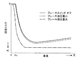
図4は、本実施形態に係る車両において、減速時のモータジェネレータ11による回生トルク(回生制動力)と車速との関係を示す特性図であり、図5は、本実施形態に係る車両において、減速時の車両の減速度と車速との関係を示す特性図である。図中、実線は、回生レベルが小のとき(つまり第1の操作パターンのとき)の特性(i)であり、破線は、回生レベルが中のとき(つまり第2の操作パターン又は第3の操作パターンのとき)の特性(ii)であり、鎖線は、回生レベルが大のとき(つまり第4の操作パターンのとき)の特性(iii)である。
FIG. 4 is a characteristic diagram showing the relationship between the regenerative torque (regenerative braking force) by the
なお、各特性は、すべて、惰行時(ブレーキ非操作時)の特性である。後述するように、制動時(ブレーキ操作時)は惰行時(図4)に比べて回生トルクが大きくされ、その結果、車両減速度も図5に比べて大きくされる。また、ブレーキ操作量が大きいほど図4に示す回生トルクがより大きくされ、その結果、図5に示す車両減速度もより大きくされる。また、図5に示す車両減速度は、図4に示す回生トルクによるものであり、最終的には、図5に示す車両減速度に、ブレーキ液圧で作動する機械式ブレーキによる車両減速度が加えられる。 Each characteristic is a characteristic when coasting (when the brake is not operated). As will be described later, regenerative torque is increased during braking (during brake operation) compared to coasting (FIG. 4), and as a result, vehicle deceleration is also increased compared to FIG. Further, as the brake operation amount is larger, the regenerative torque shown in FIG. 4 is increased, and as a result, the vehicle deceleration shown in FIG. 5 is also increased. Further, the vehicle deceleration shown in FIG. 5 is due to the regenerative torque shown in FIG. 4. Finally, the vehicle deceleration shown in FIG. 5 is caused by the mechanical deceleration operated by the brake hydraulic pressure. Added.
図4に示すように、車速に拘らず、回生レベルが小、中、大の順に回生トルクが大きくされている。また、図5に示すように、車速に拘らず、回生レベルが小、中、大の順に車両減速度が大きくされている。ただし、車速が大きくなるに従って走行抵抗が大きくなるので、たとえ図4のように車速が大きくなるに従って回生トルクが大きくならなくても、図5のように車速が大きくなるに従って車両減速度は大きくなる。 As shown in FIG. 4, regardless of the vehicle speed, the regenerative torque is increased in the order of low, medium and large regeneration levels. Further, as shown in FIG. 5, regardless of the vehicle speed, the vehicle deceleration is increased in the order of low, medium, and large regeneration levels. However, since the running resistance increases as the vehicle speed increases, even if the regenerative torque does not increase as the vehicle speed increases as shown in FIG. 4, the vehicle deceleration increases as the vehicle speed increases as shown in FIG. .
本実施形態では、図4に示すように、車速が所定の低車速Vo(例えば10km/h)以下では、クリープ力が得られるように、回生トルクはゼロとされている。そのため、図5に示すように、車速が前記低車速Vo以下では、車両には加速度が作用する。したがって、本実施形態では、車速が前記低車速Voより大きい中速域及び高速域において、車速が大きいほど車両減速度が大きくなっている。 In this embodiment, as shown in FIG. 4, when the vehicle speed is a predetermined low vehicle speed Vo (for example, 10 km / h) or less, the regenerative torque is zero so that the creep force can be obtained. Therefore, as shown in FIG. 5, when the vehicle speed is lower than the low vehicle speed Vo, acceleration acts on the vehicle. Accordingly, in the present embodiment, the vehicle deceleration increases as the vehicle speed increases in the medium speed range and the high speed range where the vehicle speed is greater than the low vehicle speed Vo.
図6は、図4に示す回生レベルが小のときの特性(i)がブレーキ操作に応じてどのように変化するかを示す特性図であり、図7は、図4に示す回生レベルが中のときの特性(ii)がブレーキ操作に応じてどのように変化するかを示す特性図であり、図8は、図4に示す回生レベルが大のときの特性(iii)がブレーキ操作に応じてどのように変化するかを示す特性図である。図中、実線は、ブレーキスイッチ26がオフのとき(つまりブレーキ非操作時)の特性であり、破線は、ブレーキ液圧が最小のとき(つまりブレーキスイッチ26がオフからオンに切り替わったとき)の特性であり、鎖線は、ブレーキ液圧が最大のときの特性である。
FIG. 6 is a characteristic diagram showing how the characteristic (i) when the regeneration level shown in FIG. 4 is small changes according to the brake operation, and FIG. 7 shows that the regeneration level shown in FIG. FIG. 8 is a characteristic diagram showing how the characteristic (ii) changes in response to the brake operation. FIG. 8 shows the characteristic (iii) when the regeneration level shown in FIG. 4 is large according to the brake operation. It is a characteristic figure which shows how it changes. In the figure, the solid line is the characteristic when the
図6、図7、図8に示すように、回生レベルに拘らず、制動時(破線及び鎖線)は惰行時(実線)に比べて回生トルクが大きくされ(したがって車両減速度が大きくされ)、また、ブレーキ操作量が大きいほど回生トルクが大きくされ(したがって車両減速度が大きくされ)ている。 As shown in FIGS. 6, 7, and 8, regardless of the regeneration level, the regenerative torque is increased (the vehicle deceleration is increased) during braking (broken line and chain line) compared to coasting (solid line), Further, the regenerative torque is increased (the vehicle deceleration is increased) as the brake operation amount is increased.
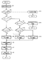
次に、図9のフローチャートを参照して、前記ECU21が行う回生制動制御の動作を説明する。なお、以下の動作では、ECU21は、図5に示す減速度と車速との関係の特性(i)、(ii)、(iii)をメモリに格納し、選択した特性から目標減速度を演算し、演算した目標減速度が実現する目標回生トルクを決定する場合について説明するが、ECU21が図4又は図6〜図8に示す回生トルクと車速との関係の特性(i)、(ii)、(iii)をメモリに格納し、選択した特性から直接目標回生トルクを決定してもよい。
Next, the regenerative braking control operation performed by the
回生制動制御がスタートすると、ECU21は、ステップS1で、前記各種センサ及びスイッチ22〜27から入力される信号を読み込む。
When the regenerative braking control is started, the
次いで、ECU21は、ステップS2で、アクセル開度センサ23からの信号に基き、運転者がアクセル操作をしているか否かを判定する。
Next, in step S2, the
その結果、運転者がアクセル操作をしているときは、ECU21は、ステップS13で、加速時の制御を実行し、リターンする。一方、運転者がアクセル操作をしていないときは、ECU21は、ステップS3で、レンジスイッチ24からの信号に基き、運転者のシフトレバー操作により選択されたレンジがDレンジか否かを判定する。
As a result, when the driver is operating the accelerator, the
その結果、Dレンジが選択されているときは、ECU21は、ステップS4で、チャージスイッチ25からの信号に基き、チャージスイッチ25がオンか否か、つまり運転者がより大きい回生制動力を要求してチャージスイッチ25をオンにしているか否かを判定する。
As a result, when the D range is selected, in step S4, the
その結果、チャージスイッチ25がオフのときは、ECU21は、ステップS5で、回生レベルが小のマップを選択し、ステップS6に進む。ここで、回生レベルが小のマップとは、図5に示す減速度と車速との関係の特性(i)、(ii)、(iii)のうち回生レベルが小の特性(i)のことである。一方、チャージスイッチ25がオンのときは、ECU21は、ステップS11で、回生レベルが中のマップを選択し、ステップS6に進む。ここで、回生レベルが中のマップとは、図5に示す減速度と車速との関係の特性(i)、(ii)、(iii)のうち回生レベルが中の特性(ii)のことである。
As a result, when the
前記ステップS3の判定の結果、Dレンジが選択されていないときは、ECU21は、ステップS9で、レンジスイッチ24からの信号に基き、運転者のシフトレバー操作により選択されたレンジがEレンジか否かを判定する。
If the D range is not selected as a result of the determination in step S3, the
その結果、Eレンジが選択されているときは、ECU21は、ステップS10で、チャージスイッチ25からの信号に基き、チャージスイッチ25がオンか否か、つまり運転者がより大きい回生制動力を要求してチャージスイッチ25をオンにしているか否かを判定する。
As a result, when the E range is selected, the
その結果、チャージスイッチ25がオフのときは、ECU21は、ステップS11で、回生レベルが中のマップを選択し、ステップS6に進む。一方、チャージスイッチ25がオンのときは、ECU21は、ステップS12で、回生レベルが大のマップを選択し、ステップS6に進む。ここで、回生レベルが大のマップとは、図5に示す減速度と車速との関係の特性(i)、(ii)、(iii)のうち回生レベルが大の特性(iii)のことである。
As a result, when the
前記ステップS9の判定の結果、Eレンジが選択されていないときは、ECU21は、ステップS14で、その他のレンジ(P,R,N)の制御を実行し、リターンする。
As a result of the determination in step S9, if the E range is not selected, the
ステップS6では、ECU21は、目標車両減速度を演算する。すなわち、ECU21は、前記ステップS5、S11又はS12で選択したマップに車速センサ22からの信号に基き特定される車速を当てはめることにより得られる車両減速度を目標車両減速度とする。その場合、ECU21は、ブレーキスイッチ26からの信号に基き、制動時等で運転者がブレーキ操作をしているか否かを判定し、運転者がブレーキ操作をしているときは、ブレーキ操作をしていないときに比べて、目標車両減速度を大きくする。また、ECU21は、ブレーキ液圧センサ27からの信号に基き、ブレーキ液圧(ブレーキ操作量)が大きいほど目標車両減速度を大きくする。
In step S6, the
次いで、ステップS7では、ECU21は、下記式(1)に基き、目標回生トルクTrを演算する。ここで、式(1)中、Wは車両重量、Kは前記ステップS6で演算した目標車両減速度、Dはタイヤ半径、Gは減速機14のギヤ比である。
Next, in step S7, the
式(1):Tr=(W×K×D)/G Formula (1): Tr = (W × K × D) / G
これにより、前記ステップS6で演算した目標車両減速度Kが実現する目標回生トルクTrが決定される。換言すれば、車速、ブレーキ操作の有無、ブレーキ操作量に応じて変化する図4又は図6〜図8に示すような特性に従った目標回生トルクが決定される。 As a result, the target regenerative torque Tr realized by the target vehicle deceleration K calculated in step S6 is determined. In other words, the target regenerative torque is determined according to the characteristics shown in FIG. 4 or FIGS. 6 to 8 that change according to the vehicle speed, the presence or absence of the brake operation, and the amount of brake operation.
次いで、ステップS8では、ECU21は、前記ステップS7で決定した目標回生トルクが発生するようにモータジェネレータ11による回生制動を実行し、リターンする。すなわち、ECU21は、目標回生トルク(目標回生制動力)に基き、モータジェネレータ11のロータのフィールドコイルに印加すべき電流値を算出し、算出した電流値の電流がフィールドコイルに印加されるようにインバータ13を制御する。
Next, in step S8, the
(3)作用等
以上のように、本実施形態に係る車両用制御装置は、車両の加速時に電力の供給を受けて車輪16を駆動する機能と、車両の減速時に回転する車輪16から動力を得て発電する機能とを備えたモータジェネレータ11が搭載された車両を制御する車両用制御装置であって、次のような特徴的構成を備えている。
(3) Operation, etc. As described above, the vehicle control apparatus according to the present embodiment receives power from the
まず、複数の走行レンジのうちのいずれか1つを選択するために移動操作されるシフトレバー31と、前記シフトレバー31のノブ部に設けられ、車両の減速時にモータジェネレータ11が発電する回生電力を増大又は減少させるために操作されるチャージスイッチ25とが備えられている。そして、車両の減速時に、シフトレバー31の移動操作で選択された走行レンジ(DレンジかEレンジか)と、チャージスイッチ25の操作状態(チャージスイッチ25がオフかオンか)とに基いて、ステップS7でモータジェネレータ11から車輪16に付与される目標回生トルク(回生制動力の大きさ)を決定し、決定した目標回生トルクが得られるようにステップS8でモータジェネレータ11を制御するECU21が備えられている。
First, a
本実施形態によれば、複数の走行レンジのうちのいずれか1つを選択するために移動操作されるシフトレバー31の他に、車両の減速時にモータジェネレータ11が発電する回生電力を増大又は減少させるために操作されるチャージスイッチ25が設けられているので、運転者は、前記チャージスイッチ25を操作することにより、シフトレバー31を移動操作することなく、減速時の回生トルク(回生制動力)を簡便に調整することができる。しかも、前記チャージスイッチ25は、シフトレバー31のノブ部に設けられているので、運転者は、シフトレバー31でレンジを選択するときと同様の姿勢で回生トルクを調整することができ、回生トルクを調整する操作の負担が軽くて済む。以上により、本実施形態によれば、運転者は操作性よく減速時の回生制動力を調整することができる。
According to the present embodiment, in addition to the
加えて、本実施形態によれば、シフトレバー31によるレンジの選択によっても、またチャージスイッチ25によるオン又はオフの選択によっても、回生レベルひいては回生制動力を個別に切り替えることができるので、次のような作用も奏される。すなわち、チャージスイッチ25を設けず、シフトレバー31によるレンジの選択のみによって回生レベルを切り替える場合は、回生レベルの切替えに随伴して、加速時におけるモータジェネレータ11の出力レベルも切り替わってしまうという不具合がある(図3参照)。つまり、モータジェネレータ11の出力レベルをそのままにして回生レベルだけを切り替えることができないのである。これに対し、本実施形態では、チャージスイッチ25を設けることにより、走行レンジをそのままにして、つまり加速時の出力レベルをそのままにして、減速時の回生レベルひいては回生制動力のみを切り替えることが可能となる。
In addition, according to the present embodiment, the regeneration level and thus the regenerative braking force can be individually switched by selecting the range by the
本実施形態では、シフトレバー31で選択可能な走行レンジとして、Dレンジと、加速時のモータジェネレータ11の出力がDレンジよりも控えられるEレンジ(エコレンジ)とが設けられている。また、チャージスイッチ25は、オン又はオフの2段階に操作されるスイッチである。そして、ECU21は、シフトレバー31でDレンジが選択され且つチャージスイッチ25がオフの第1の操作パターンのとき(ステップS5)、回生レベルが小のマップを選択する。すなわち、減速時の回生制動力を第1のレベルに設定する。また、ECU21は、シフトレバー31でDレンジが選択され且つチャージスイッチ25がオンの第2の操作パターンのとき(ステップS11)、回生レベルが中のマップを選択する。すなわち、減速時の回生制動力を第1のレベルよりも大きい第2のレベルに設定する。また、ECU21は、シフトレバー31でEレンジが選択され且つチャージスイッチ25がオフの第3の操作パターンのとき(ステップS11)、回生レベルが中のマップを選択する。すなわち、減速時の回生制動力を第1のレベルよりも大きい第3のレベルに設定する。また、ECU21は、シフトレバー31でEレンジが選択され且つチャージスイッチ25がオンの第4の操作パターンのとき(ステップS12)、回生レベルが大のマップを選択する。すなわち、減速時の回生制動力を第2のレベル及び第3のレベルよりも大きい第4のレベルに設定する。
In the present embodiment, a D range and an E range (eco range) in which the output of the
この構成によれば、シフトレバー31で選択されるDとEの2つのレンジと、チャージスイッチ25のオン又はオフとの組み合わせにより、第1〜第4の4つの操作パターンが得られ、各操作パターンに応じて種々の回生制動力のいずれか1つが決定される。その場合に、加速時のモータジェネレータ11の出力が相対的に大きいDレンジでチャージスイッチ25がオフのときは(ステップS5)、最も小さい第1のレベルの回生制動力が決定されるので、アクセル操作(アクセルオン)からアクセル非操作(アクセルオフ)に切り替わったときの減速度が弱めとなり、加速度の変化が小さいよりスムーズな減速走行が実現される。一方、加速時のモータジェネレータ11の出力が相対的に小さいEレンジでチャージスイッチ25がオンのときは(ステップS12)、最も大きい第4のレベルの回生制動力が決定されるので、アクセル操作(アクセルオン)からアクセル非操作(アクセルオフ)に切り替わった後の発電量が多めとなり、経済走行レンジ(エコレンジ)における減速時のエネルギ回収が十分に行われる。
According to this configuration, the first to fourth operation patterns are obtained by the combination of the two ranges D and E selected by the
本実施形態では、図3に示したように、第2の操作パターンの回生レベルと第3の操作パターンの回生レベルとが相互に同一の「中」の大きさとされ、その結果、第2の操作パターンの回生制動力と第3の操作パターンの回生制動力とが相互に同一の大きさとされている。 In the present embodiment, as shown in FIG. 3, the regeneration level of the second operation pattern and the regeneration level of the third operation pattern are set to the same “medium” magnitude. The regenerative braking force of the operation pattern and the regenerative braking force of the third operation pattern have the same magnitude.
この構成によれば、Dレンジでチャージスイッチ25がオンのときと、Eレンジでチャージスイッチ25がオフのときとで、得られる減速度が同じになるので、第1の操作パターンよりも大きく、第4の操作パターンよりも小さい中間の減速度が第2の操作パターン及び第3の操作パターンのいずれを選択しても共通に得られることになる。これにより、設定可能な減速度のレベルが大、中、小の3段階になるので、運転者は現在設定されている減速度のレベルを容易に把握することができ、操作性が向上する。
According to this configuration, when the
本実施形態では、図5に示したように、ECU21は、中速域では、車速が大きいほど車両減速度がリニアに大きくなるようにステップS7で目標回生トルクを決定する。そのため、使用頻度の高い中速域(例えば40〜100km/h)では、車速が大きいほど車両減速度がリニアに大きくなるので、車両走行性の向上が図られる。
In the present embodiment, as shown in FIG. 5, the
本実施形態では、図6〜図8に示したように、ECU21は、ブレーキ操作量が大きいほど車両減速度が大きくなるようにステップS7で目標回生トルクを決定する。そのため、運転者が制動力を大きくしようとしてブレーキ操作をしたときに、ブレーキ操作量が大きいほど車両減速度が大きくなるので、運転者は車両の性能に安心感を持って運転することができる。
In this embodiment, as shown in FIGS. 6 to 8, the
なお、前記実施形態では、回生レベルが相違する走行レンジとしてDレンジとEレンジとの2つのレンジを設けたが、これに限らず、回生レベルが相違する走行レンジとして3つ以上のレンジを設けても構わない。 In the above embodiment, the two ranges of the D range and the E range are provided as the travel ranges having different regeneration levels. However, the present invention is not limited to this, and three or more ranges are provided as the travel ranges having different regeneration levels. It doesn't matter.
また、前記実施形態では、第2の操作パターンの回生レベルと第3の操作パターンの回生レベルとを相互に同一の大きさとし、その結果、第2の操作パターンの回生制動力と第3の操作パターンの回生制動力とを相互に同一の大きさとしたが、これに限らず、第2の操作パターンの回生レベルと第3の操作パターンの回生レベルとを相違する大きさとし、その結果、第2の操作パターンの回生制動力と第3の操作パターンの回生制動力とを相違する大きさとしても構わない。 In the embodiment, the regenerative level of the second operation pattern and the regenerative level of the third operation pattern have the same magnitude, and as a result, the regenerative braking force and the third operation of the second operation pattern are the same. The regenerative braking force of the pattern is the same as each other. However, the present invention is not limited to this, and the regenerative level of the second operation pattern is different from the regenerative level of the third operation pattern. The regenerative braking force of the operation pattern may be different from the regenerative braking force of the third operation pattern.
11 モータジェネレータ(電動機)
12 高電圧バッテリ
13 インバータ
14 減速機
21 ECU(制御手段)
22 車速センサ
23 アクセル開度センサ
24 レンジスイッチ
25 チャージスイッチ
26 ブレーキスイッチ
27 ブレーキ液圧センサ
31 シフトレバー
11 Motor generator (electric motor)
12
22
Claims (3)
複数の走行レンジのうちのいずれか1つを選択するために移動操作されるシフトレバーと、
前記シフトレバーに設けられ、車両の減速時に電動機が発電する回生電力を増大又は減少させるために操作されるチャージスイッチと、
車両の減速時に、前記シフトレバーの移動操作で選択された走行レンジと、前記チャージスイッチの操作状態とに基いて、前記電動機から車輪に付与される回生制動力の大きさを決定し、決定した大きさの回生制動力が得られるように前記電動機を制御する制御手段とを有し、
前記シフトレバーで選択可能な走行レンジとして、第1のレンジと、加速時の電動機の出力が第1のレンジよりも控えられる第2のレンジとが設けられ、
前記チャージスイッチは、オン又はオフの2段階に操作されるスイッチであり、
前記制御手段は、
前記シフトレバーで前記第1のレンジが選択され、且つ前記チャージスイッチがオフのとき、減速時の回生制動力を第1のレベルに設定し、
前記シフトレバーで前記第1のレンジが選択され、且つ前記チャージスイッチがオンのとき、減速時の回生制動力を第1のレベルよりも大きい第2のレベルに設定し、
前記シフトレバーで前記第2のレンジが選択され、且つ前記チャージスイッチがオフのとき、減速時の回生制動力を第1のレベルよりも大きい第3のレベルに設定し、
前記シフトレバーで前記第2のレンジが選択され、且つ前記チャージスイッチがオンのとき、減速時の回生制動力を第2のレベル及び第3のレベルよりも大きい第4のレベルに設定し、
前記第2のレベルの回生制動力と前記第3のレベルの回生制動力とは相互に同一の大きさであることを特徴とする車両用制御装置。 A vehicle control device that controls a vehicle equipped with an electric motor having a function of driving a wheel by receiving power supply when the vehicle is accelerated and a function of generating power by obtaining power from a wheel that rotates when the vehicle is decelerated. There,
A shift lever that is moved to select any one of a plurality of travel ranges;
A charge switch provided on the shift lever and operated to increase or decrease the regenerative power generated by the motor when the vehicle decelerates;
When the vehicle decelerates, the magnitude of the regenerative braking force applied to the wheels from the motor is determined based on the travel range selected by the shift lever movement operation and the operation state of the charge switch. have a control means for controlling said electric motor so as regenerative braking force of magnitude is obtained,
As the travel range that can be selected by the shift lever, a first range and a second range in which the output of the motor at the time of acceleration is less than the first range are provided,
The charge switch is a switch operated in two stages, on or off,
The control means includes
When the first range is selected by the shift lever and the charge switch is off, the regenerative braking force during deceleration is set to the first level,
When the first range is selected by the shift lever and the charge switch is on, the regenerative braking force during deceleration is set to a second level that is greater than the first level;
When the second range is selected by the shift lever and the charge switch is off, the regenerative braking force during deceleration is set to a third level that is greater than the first level;
When the second range is selected by the shift lever and the charge switch is on, the regenerative braking force during deceleration is set to a second level and a fourth level that is greater than the third level;
The vehicle control apparatus according to claim 2, wherein the second level regenerative braking force and the third level regenerative braking force have the same magnitude .
前記制御手段は、中速域では、車速が大きいほど減速度がリニアに大きくなるように回生制動力の大きさを決定することを特徴とする車両用制御装置。 The vehicle control device according to claim 1 ,
The control device for a vehicle, wherein the control means determines the magnitude of the regenerative braking force so that the deceleration increases linearly as the vehicle speed increases in the medium speed range.
前記制御手段は、ブレーキ操作量が大きいほど減速度が大きくなるように回生制動力の大きさを決定することを特徴とする車両用制御装置。
The vehicle control device according to claim 1 or 2 ,
The control device for a vehicle determines the magnitude of the regenerative braking force so that the deceleration increases as the brake operation amount increases.
Priority Applications (1)
| Application Number | Priority Date | Filing Date | Title |
|---|---|---|---|
| JP2012200057A JP5929656B2 (en) | 2012-09-12 | 2012-09-12 | Vehicle control device |
Applications Claiming Priority (1)
| Application Number | Priority Date | Filing Date | Title |
|---|---|---|---|
| JP2012200057A JP5929656B2 (en) | 2012-09-12 | 2012-09-12 | Vehicle control device |
Publications (2)
| Publication Number | Publication Date |
|---|---|
| JP2014057417A JP2014057417A (en) | 2014-03-27 |
| JP5929656B2 true JP5929656B2 (en) | 2016-06-08 |
Family
ID=50614275
Family Applications (1)
| Application Number | Title | Priority Date | Filing Date |
|---|---|---|---|
| JP2012200057A Expired - Fee Related JP5929656B2 (en) | 2012-09-12 | 2012-09-12 | Vehicle control device |
Country Status (1)
| Country | Link |
|---|---|
| JP (1) | JP5929656B2 (en) |
Families Citing this family (4)
| Publication number | Priority date | Publication date | Assignee | Title |
|---|---|---|---|---|
| JP2017143685A (en) * | 2016-02-12 | 2017-08-17 | 三菱自動車工業株式会社 | Regeneration control device |
| WO2018189904A1 (en) * | 2017-04-14 | 2018-10-18 | 日産自動車株式会社 | Electric vehicle control method and electric vehicle control device |
| KR102020566B1 (en) * | 2018-01-18 | 2019-11-05 | 주식회사 블루윙모터스 | Apparatus and metod for controlling electrical energy in two or three wheeled vehicle |
| CN118404998B (en) * | 2024-07-03 | 2024-08-30 | 潍坊华源汽车部件有限公司 | Central control system for safety auxiliary brake |
Family Cites Families (3)
| Publication number | Priority date | Publication date | Assignee | Title |
|---|---|---|---|---|
| JPH10174213A (en) * | 1996-12-06 | 1998-06-26 | Toyota Motor Corp | Control apparatus for electric vehicle |
| JP5387460B2 (en) * | 2010-03-12 | 2014-01-15 | トヨタ自動車株式会社 | Vehicle and control method thereof |
| JP2012136191A (en) * | 2010-12-27 | 2012-07-19 | Toyota Motor Corp | Vehicle control system |
-
2012
- 2012-09-12 JP JP2012200057A patent/JP5929656B2/en not_active Expired - Fee Related
Also Published As
| Publication number | Publication date |
|---|---|
| JP2014057417A (en) | 2014-03-27 |
Similar Documents
| Publication | Publication Date | Title |
|---|---|---|
| EP2749446B1 (en) | Regenerative brake control device | |
| US8965609B2 (en) | Electric vehicle | |
| KR101875641B1 (en) | System and method for torque control of electric vehicle | |
| US10377242B2 (en) | Regenerative brake control device | |
| CN103043056A (en) | Method of controlling vehicle wheel axle torque and control system for same | |
| JP5538633B2 (en) | Electric vehicle | |
| JP6682952B2 (en) | Regenerative control device | |
| JP5929656B2 (en) | Vehicle control device | |
| JP2017028905A (en) | Regeneration control device for vehicle | |
| JP2013215063A (en) | Creep control device of electric vehicle | |
| JP6291671B2 (en) | Vehicle control device | |
| JP2004215447A (en) | Travel controller for vehicle | |
| JP5327177B2 (en) | Vehicle control system | |
| JP2006050811A (en) | Electric vehicle | |
| JP5896315B2 (en) | Regenerative brake control device | |
| JP6372772B2 (en) | Regenerative brake control device | |
| JP2012090396A (en) | Driving force controller of vehicle | |
| JP5896316B2 (en) | Regenerative brake control device | |
| WO2022024770A1 (en) | Vehicle travel control device | |
| JP6202411B2 (en) | Regenerative brake control device | |
| JP6202410B2 (en) | Regenerative brake control device | |
| WO2022230545A1 (en) | Shift device for electric vehicle | |
| JP5896311B2 (en) | Regenerative brake control device | |
| JP2024111908A (en) | Display device for electric vehicle |
Legal Events
| Date | Code | Title | Description |
|---|---|---|---|
| A621 | Written request for application examination |
Free format text: JAPANESE INTERMEDIATE CODE: A621 Effective date: 20150312 |
|
| A977 | Report on retrieval |
Free format text: JAPANESE INTERMEDIATE CODE: A971007 Effective date: 20151210 |
|
| A131 | Notification of reasons for refusal |
Free format text: JAPANESE INTERMEDIATE CODE: A131 Effective date: 20151215 |
|
| A521 | Request for written amendment filed |
Free format text: JAPANESE INTERMEDIATE CODE: A523 Effective date: 20160208 |
|
| TRDD | Decision of grant or rejection written | ||
| A01 | Written decision to grant a patent or to grant a registration (utility model) |
Free format text: JAPANESE INTERMEDIATE CODE: A01 Effective date: 20160405 |
|
| A61 | First payment of annual fees (during grant procedure) |
Free format text: JAPANESE INTERMEDIATE CODE: A61 Effective date: 20160418 |
|
| R150 | Certificate of patent or registration of utility model |
Ref document number: 5929656 Country of ref document: JP Free format text: JAPANESE INTERMEDIATE CODE: R150 |
|
| LAPS | Cancellation because of no payment of annual fees |