JP5387444B2 - Conveying apparatus and substrate bonding apparatus - Google Patents

Conveying apparatus and substrate bonding apparatus Download PDF

Info

Publication number
JP5387444B2
JP5387444B2 JP2010040111A JP2010040111A JP5387444B2 JP 5387444 B2 JP5387444 B2 JP 5387444B2 JP 2010040111 A JP2010040111 A JP 2010040111A JP 2010040111 A JP2010040111 A JP 2010040111A JP 5387444 B2 JP5387444 B2 JP 5387444B2
Authority
JP
Japan
Prior art keywords
temperature
substrate
semiconductor substrate
mounting
holding member
Prior art date
Legal status (The legal status is an assumption and is not a legal conclusion. Google has not performed a legal analysis and makes no representation as to the accuracy of the status listed.)
Active
Application number
JP2010040111A
Other languages
Japanese (ja)
Other versions
JP2011176197A (en
JP2011176197A5 (en
Inventor
慶一 田中
Current Assignee (The listed assignees may be inaccurate. Google has not performed a legal analysis and makes no representation or warranty as to the accuracy of the list.)
Nikon Corp
Original Assignee
Nikon Corp
Priority date (The priority date is an assumption and is not a legal conclusion. Google has not performed a legal analysis and makes no representation as to the accuracy of the date listed.)
Filing date
Publication date
Application filed by Nikon Corp filed Critical Nikon Corp
Priority to JP2010040111A priority Critical patent/JP5387444B2/en
Publication of JP2011176197A publication Critical patent/JP2011176197A/en
Publication of JP2011176197A5 publication Critical patent/JP2011176197A5/ja
Application granted granted Critical
Publication of JP5387444B2 publication Critical patent/JP5387444B2/en
Active legal-status Critical Current
Anticipated expiration legal-status Critical

Links

Images

Description

本発明は、搬送装置および基板接合装置に関する。   The present invention relates to a transfer device and a substrate bonding apparatus.

各基板に対して複数種類の処理をする処理装置は、基板を搭載して搬送する複数の搬送部を備える。複数の搬送部は、搬送区間に応じて分担が割り当てられる(特許文献1参照)。
[先行技術文献]
[特許文献]
[特許文献1]特許第2859849号公報
A processing apparatus that performs a plurality of types of processing on each substrate includes a plurality of transport units that mount and transport the substrate. Shares are assigned to the plurality of transport units according to the transport section (see Patent Document 1).
[Prior art documents]
[Patent Literature]
[Patent Document 1] Japanese Patent No. 2859849

基板に形成される装置の精度が高くなるにつれて、基板自体の取り扱いにも高い精度が求められる。しかしながら、搬送部のそれぞれは予め割り当てられた区間で基板を搬送するに過ぎず、搬送部および基板の各々において変化する状態を忖度することはなかった。   As the accuracy of the device formed on the substrate becomes higher, higher accuracy is required for handling the substrate itself. However, each of the transporting units only transports the substrate in a pre-assigned section, and never changes the state that changes in each of the transporting unit and the substrate.

そこで、上記課題を解決すべく、本発明の第一態様として、素子を形成された基板を搬送する搬送装置であって、基板を搭載する複数の搭載部と、複数の搭載部の温度を個別に測定する測温部と、測温部の測定結果に応じて、複数の搭載部のいずれかを選択して基板を搭載させる制御部とを備える搬送装置が提供される。   Accordingly, in order to solve the above problems, as a first aspect of the present invention, there is provided a transfer device for transferring a substrate on which an element is formed, wherein a plurality of mounting portions for mounting the substrate and temperatures of the plurality of mounting portions are individually set. There is provided a transfer device including a temperature measuring unit to be measured and a control unit that selects any of a plurality of mounting units and mounts a substrate in accordance with the measurement result of the temperature measuring unit.

また、本発明の第二態様として、素子を形成された基板および基板を保持する基板保持部材を互いに積層した状態で搬送する搬送装置であって、基板および基板保持部材を搭載する複数の搭載部と、複数の搭載部の温度を個別に測定する測温部と、測温部の測定結果に応じて、複数の搭載部のいずれかを選択して基板および基板保持部材を搭載させる制御部とを備える搬送装置が提供される。   According to a second aspect of the present invention, there is provided a transfer device for transferring a substrate on which an element is formed and a substrate holding member for holding the substrate in a stacked state, and a plurality of mounting portions for mounting the substrate and the substrate holding member A temperature measuring unit that individually measures the temperature of the plurality of mounting units, and a control unit that selects one of the plurality of mounting units and mounts the substrate and the substrate holding member according to the measurement result of the temperature measuring unit; Is provided.

なお、上記の発明の概要は、本発明の必要な特徴の全てを列挙したものではない。また、これらの特徴群のサブコンビネーションもまた、発明となりうる。   It should be noted that the above summary of the invention does not enumerate all the necessary features of the present invention. In addition, a sub-combination of these feature groups can also be an invention.

基板接合装置100全体の模式的水平断面図である。1 is a schematic horizontal sectional view of an entire substrate bonding apparatus 100. FIG. 基板接合装置100全体の模式的縦断面図である。1 is a schematic longitudinal sectional view of an entire substrate bonding apparatus 100. FIG. 加圧装置170の模式的縦断面図である。2 is a schematic longitudinal sectional view of a pressurizing device 170. FIG. 冷却装置180の模式的縦断面図である。2 is a schematic longitudinal sectional view of a cooling device 180. FIG. 環境ローダ160の平面図である。3 is a plan view of an environment loader 160. FIG. 環境ローダ160の平面図である。3 is a plan view of an environment loader 160. FIG. フォーク162の斜視図である。3 is a perspective view of a fork 162. FIG. 基板102の状態を示す図である。It is a figure which shows the state of the board | substrate 102. FIG. 基板102の状態を示す図である。It is a figure which shows the state of the board | substrate 102. FIG. 基板102の状態を示す図である。It is a figure which shows the state of the board | substrate 102. FIG. 基板102の状態の変遷を示す図である。It is a figure which shows the transition of the state of the board | substrate 102. FIG. 単一の積層体106の温度遷移を示すダイアグラムである。6 is a diagram showing temperature transition of a single laminate 106. 複数の積層体106の温度遷移を示すダイアグラムである。3 is a diagram showing temperature transition of a plurality of stacked bodies 106.

以下、発明の実施の形態を通じて本発明を説明するが、以下の実施形態は特許請求の範囲にかかる発明を限定するものではない。また、実施形態の中で説明されている特徴の組み合わせの全てが発明の解決手段に必須であるとは限らない。   Hereinafter, the present invention will be described through embodiments of the invention, but the following embodiments do not limit the invention according to the claims. In addition, not all the combinations of features described in the embodiments are essential for the solving means of the invention.

図1は、基板接合装置100の模式的水平断面図である。また、図2は、基板接合装置100の模式的縦断面図である。図1および図2で共通の要素には同じ参照番号を付す。以下、これら図面を参照して、基板接合装置100全体の構造を説明する。   FIG. 1 is a schematic horizontal sectional view of the substrate bonding apparatus 100. FIG. 2 is a schematic longitudinal sectional view of the substrate bonding apparatus 100. Elements common to FIGS. 1 and 2 are given the same reference numerals. Hereinafter, the overall structure of the substrate bonding apparatus 100 will be described with reference to these drawings.

基板接合装置100は、断熱壁112により仕切られた室温部98および高温部99を有する筐体110の内部に主に形成される。室温部98には、大気ローダ120、アライナ130、基板プリアライナ142、ホルダプリアライナ144、ホルダプリアライナ144およびホルダストッカ146が配される。高温部99には、環境ローダ160、加熱加圧装置170および冷却装置180が配される。室温部98および高温部99は、ロードロック150を介して結合される。   The substrate bonding apparatus 100 is mainly formed inside a housing 110 having a room temperature part 98 and a high temperature part 99 partitioned by a heat insulating wall 112. In the room temperature portion 98, an atmospheric loader 120, an aligner 130, a substrate pre-aligner 142, a holder pre-aligner 144, a holder pre-aligner 144, and a holder stocker 146 are arranged. In the high temperature part 99, an environmental loader 160, a heating and pressing device 170, and a cooling device 180 are arranged. The room temperature portion 98 and the high temperature portion 99 are coupled via a load lock 150.

なお、筐体110の外部には、制御部114が配される。制御部114は、以下に説明する基板接合装置100の各部の動作を統括して制御する。また、基板接合装置100を動作させる場合の操作部となる。更に、制御部114は、基板接合装置100の動作状態を表示する表示部にもなる。   A control unit 114 is disposed outside the housing 110. The control unit 114 controls the overall operation of each unit of the substrate bonding apparatus 100 described below. Moreover, it becomes an operation part in the case of operating the board | substrate bonding apparatus 100. FIG. Further, the control unit 114 also serves as a display unit that displays the operation state of the substrate bonding apparatus 100.

室温部98は、筐体110の外部と同じ大気圧環境にある。室温部98において、筐体110の外側の一面には、複数のFOUP(Front Opening Unified Pod)116が外側から装着される。FOUP116は、筐体110に対して個別に取り外しできる。また、FOUP116の各々は複数の基板102を収容する。   The room temperature portion 98 is in the same atmospheric pressure environment as the outside of the housing 110. In the room temperature portion 98, a plurality of front opening unified pods (FOUPs) 116 are attached to the outer surface of the casing 110 from the outside. The FOUP 116 can be individually removed from the housing 110. Each of the FOUPs 116 accommodates a plurality of substrates 102.

よって、FOUP116を基板接合装置100に装着することにより、複数の基板102を一括して基板接合装置100に装填できる。また、後述するように基板102を接合して形成された積層型基板108は、FOUP116に回収されて一括して搬出される。   Therefore, by mounting the FOUP 116 on the substrate bonding apparatus 100, a plurality of substrates 102 can be loaded into the substrate bonding apparatus 100 at once. Further, as will be described later, the laminated substrate 108 formed by bonding the substrates 102 is collected by the FOUP 116 and carried out at once.

室温部98の内部において、FOUP116の前方(図中では上方)に、大気ローダ120が配される。大気ローダ120は、フォーク122、支持アーム124およびフォールディングアーム126を有する。フォーク122は、支持アーム124に支持され、支持アーム124の伸縮に応じて進退する。また、大気ローダ120は、基板接合装置100の底面に配されたガイドレール121に沿って移動する。   Inside the room temperature section 98, an atmospheric loader 120 is disposed in front of the FOUP 116 (upward in the drawing). The atmospheric loader 120 has a fork 122, a support arm 124 and a folding arm 126. The fork 122 is supported by the support arm 124 and advances and retreats according to the expansion and contraction of the support arm 124. The atmospheric loader 120 moves along a guide rail 121 arranged on the bottom surface of the substrate bonding apparatus 100.

これにより、大気ローダ120は、ガイドレール121に沿って移動しつつ、フォールディングアーム126を伸縮させて、周囲に配されたFOUP116、アライナ130、基板プリアライナ142、ホルダプリアライナ144、ホルダストッカ146およびロードロック150の相互の間で、基板102および基板ホルダ104の少なくとも一方を搬送する。   As a result, the atmospheric loader 120 moves along the guide rail 121 and expands and contracts the folding arm 126 so that the FOUP 116, the aligner 130, the substrate pre-aligner 142, the holder pre-aligner 144, the holder stocker 146, and the load that are disposed around the atmosphere loader 120 are expanded. At least one of the substrate 102 and the substrate holder 104 is transported between the locks 150.

基板プリアライナ142は、大気ローダ120により、FOUP116から取り出された基板102が1枚ずつ搬入される。基板プリアライナ142は、搬入された基板102を回転または移動させた後に大気ローダ120に搭載し直すことにより、大気ローダ120に対する基板102の搭載位置と、大気ローダ120に対するノッチの向きを調整する。   The substrate pre-aligner 142 carries the substrates 102 taken out from the FOUP 116 one by one by the atmospheric loader 120. The substrate pre-aligner 142 adjusts the mounting position of the substrate 102 with respect to the atmospheric loader 120 and the orientation of the notch with respect to the atmospheric loader 120 by rotating or moving the loaded substrate 102 and then mounting it again on the atmospheric loader 120.

これにより、基板102は大気ローダ120のフォーク122に対して一定の精度で位置合わせされる。よって、後述するように基板102を基板ホルダ104に搭載する場合に、極端に大きな位置ずれが生じることが防止される。   Thus, the substrate 102 is aligned with a certain accuracy with respect to the fork 122 of the atmospheric loader 120. Therefore, when the substrate 102 is mounted on the substrate holder 104 as will be described later, an extremely large positional shift is prevented.

ホルダプリアライナ144は、大気ローダ120により、ホルダストッカ146から取り出された基板ホルダ104を1枚ずつ搬入される。ホルダプリアライナ144は、搬入された基板ホルダ104を予め定めた位置に載置させる。これにより、プリアライメントされた基板102が搬入された場合に、基板102および基板ホルダ104の相対位置を、一定の精度で位置合わせできる。   The holder pre-aligner 144 carries the substrate holders 104 taken out from the holder stocker 146 one by one by the atmospheric loader 120. The holder pre-aligner 144 places the carried-in substrate holder 104 at a predetermined position. Thereby, when the pre-aligned substrate 102 is carried in, the relative positions of the substrate 102 and the substrate holder 104 can be aligned with a certain accuracy.

なお、ホルダストッカ146は、複数の基板ホルダ104を収容して待機させる。基板ホルダ104の各々は、セラミックス、金属等の曲げ剛性が高い材料により形成され、基板102の面積よりも広い平坦な保持面を有する。また、基板ホルダ104は、当該保持面に基板102を吸着させる静電チャック、真空チャック等の基板保持機構を有する。   The holder stocker 146 accommodates a plurality of substrate holders 104 and makes them stand by. Each of the substrate holders 104 is formed of a material having high bending rigidity such as ceramics or metal, and has a flat holding surface wider than the area of the substrate 102. The substrate holder 104 has a substrate holding mechanism such as an electrostatic chuck or a vacuum chuck that attracts the substrate 102 to the holding surface.

これにより、基板ホルダ104は、基板102を一枚ずつ保持して脆い基板102を保護し、基板接合装置100における基板102の取り扱いを容易にする。なお、少なくとも基板接合装置100が稼働している期間は、基板ホルダ104が、基板接合装置100の外部に取り出されることはない。   Thereby, the substrate holder 104 protects the fragile substrate 102 by holding the substrates 102 one by one, and facilitates the handling of the substrate 102 in the substrate bonding apparatus 100. Note that the substrate holder 104 is not taken out of the substrate bonding apparatus 100 at least during the period in which the substrate bonding apparatus 100 is operating.

アライナ130は、剛硬なフレーム132に支持された下ステージ134および上ステージ136を有する。上ステージ136は、フレーム132の天面に下向きに固定される。下ステージ134は、駆動部131を介してフレーム132の底面から支持される。駆動部131は、図中に矢印X、Yにより示す水平方向に、下ステージ134を移動させる。また、下ステージ134は、図示していない駆動部により、水平面に対して揺動すると共に、矢印Zで示す方向に昇降もする。   The aligner 130 has a lower stage 134 and an upper stage 136 supported by a rigid frame 132. The upper stage 136 is fixed downward on the top surface of the frame 132. The lower stage 134 is supported from the bottom surface of the frame 132 via the drive unit 131. The drive unit 131 moves the lower stage 134 in the horizontal direction indicated by arrows X and Y in the drawing. Further, the lower stage 134 is swung with respect to the horizontal plane by a drive unit (not shown) and is also moved up and down in the direction indicated by the arrow Z.

ホルダプリアライナ144において搭載された基板102を保持した基板ホルダ104は、大気ローダ120によりアライナ130に搬入される。アライナ130においては、それぞれが基板102を保持した基板ホルダ104が、下ステージ134および上ステージ136に搭載される。   The substrate holder 104 holding the substrate 102 mounted on the holder pre-aligner 144 is carried into the aligner 130 by the atmospheric loader 120. In the aligner 130, the substrate holder 104 that holds the substrate 102 is mounted on the lower stage 134 and the upper stage 136.

下向きの上ステージ136には、大気ローダ120が基板ホルダ104を反転させた上で保持させる。これにより、アライナ130において、一対の基板102および基板ホルダ104が互いに対向する。   The atmospheric loader 120 inverts and holds the substrate holder 104 on the downward upward stage 136. Thereby, in the aligner 130, a pair of board | substrate 102 and the board | substrate holder 104 mutually oppose.

アライナ130は、下ステージ134を移動または揺動させることにより、一対の基板102を相互に位置合わせする。位置合わせされた一対の基板102は、下ステージ134および上ステージ136の間で一対の基板ホルダ104に挟まれて仮接合される。位置合わせして仮接合された一対の基板102は、これを挟む一対の基板ホルダ104と共に、再び大気ローダ120に搬送されてロードロック150に搬入される。   The aligner 130 aligns the pair of substrates 102 with each other by moving or swinging the lower stage 134. The aligned pair of substrates 102 is sandwiched and temporarily joined between the pair of substrate holders 104 between the lower stage 134 and the upper stage 136. The pair of substrates 102 that have been aligned and temporarily joined together with the pair of substrate holders 104 sandwiching the substrate 102 are conveyed again to the atmospheric loader 120 and carried into the load lock 150.

なお、アライナ130は、筐体110に対して、防振脚138を介して支持される。これにより、大気ローダ120、ロードロック150、環境ローダ160、加熱加圧装置170等の動作により生じる振動が、アライナ130の位置合わせ精度に与える影響が抑制される。また、筐体110内において室温部98は温度管理され、例えば室温に保たれる。これにより、アライナ130の位置合わせ精度が維持される。   The aligner 130 is supported with respect to the housing 110 via the vibration isolation legs 138. Thereby, the influence which the vibration which arises by operation | movement of the air | atmosphere loader 120, the load lock 150, the environmental loader 160, the heating-and-pressing apparatus 170 has on the alignment accuracy of the aligner 130 is suppressed. In addition, the room temperature portion 98 is temperature-controlled in the housing 110, and is kept at room temperature, for example. Thereby, the alignment accuracy of the aligner 130 is maintained.

ロードロック150は、大気圧環境の室温部98側と、真空環境の高温部99側とに、個別に開閉するシャッタ152、154を有する。シャッタ152、154は、室温部98およびロードロック150の間と、高温部99およびロードロック150の間とをそれぞれ気密に遮蔽する。また、ロードロック150の内部は、排気して真空環境にすることも、大気を導入して大気圧環境に戻すこともできる。これにより、室温部98の大気圧環境と高温部99の真空環境とをそれぞれ維持しつつ、室温部98および高温部99の間で基板102および基板ホルダ104を受け渡しできる。   The load lock 150 includes shutters 152 and 154 that open and close individually on the room temperature portion 98 side in the atmospheric pressure environment and the high temperature portion 99 side in the vacuum environment. The shutters 152 and 154 hermetically shield between the room temperature portion 98 and the load lock 150 and between the high temperature portion 99 and the load lock 150, respectively. The interior of the load lock 150 can be evacuated to a vacuum environment, or the atmosphere can be returned to an atmospheric pressure environment. Thus, the substrate 102 and the substrate holder 104 can be transferred between the room temperature portion 98 and the high temperature portion 99 while maintaining the atmospheric pressure environment of the room temperature portion 98 and the vacuum environment of the high temperature portion 99, respectively.

高温部99の略中央には、環境ローダ160が配される。環境ローダ160は、フォーク162、262、アーム164、264、共通支持部168、フォールディングアーム166および支柱169を有する。   An environmental loader 160 is disposed substantially at the center of the high temperature part 99. The environment loader 160 includes forks 162 and 262, arms 164 and 264, a common support 168, a folding arm 166, and a column 169.

一対のフォーク162、262は、共通支持部168を介して、フォールディングアーム166の一端に共通に支持される。フォールディングアーム166の他端は、支柱169の上端に、回動可能に支持される。支柱169は、筐体110に対して固定される。このような構造により、環境ローダ160は、周囲に配されたロードロック150、加熱加圧装置170および冷却装置180の相互の間で、積層体106を搬送できる。   The pair of forks 162 and 262 are supported in common on one end of the folding arm 166 via a common support portion 168. The other end of the folding arm 166 is rotatably supported by the upper end of the support column 169. The support 169 is fixed to the housing 110. With such a structure, the environmental loader 160 can transport the stacked body 106 between the load lock 150, the heating / pressurizing device 170, and the cooling device 180 arranged around the environment loader 150.

なお、環境ローダ160は、仮接合された一対の基板102と、それを挟む一対の基板ホルダ104とを含む積層体106を搬送する。このため、当該積層体106の搬送が、アライナ130からロードロック150までの短距離に限られる大気ローダ120に比較すると、環境ローダ160の耐荷重は大きい。   The environmental loader 160 conveys the stacked body 106 including the pair of temporarily bonded substrates 102 and the pair of substrate holders 104 that sandwich the substrate 102. For this reason, the load capacity of the environmental loader 160 is larger than that of the atmospheric loader 120 that transports the laminate 106 to a short distance from the aligner 130 to the load lock 150.

高温部99において、環境ローダ160の周囲には、ロードロック150、複数の加熱加圧装置170および冷却装置180が配される。また、ロードロック150、加熱加圧装置170および冷却装置180の間は、気密壁156により相互に気密に連結される。更に、気密壁156の内部は、真空ポンプ118に結合される。   In the high temperature part 99, a load lock 150, a plurality of heating / pressurizing devices 170 and a cooling device 180 are arranged around the environment loader 160. The load lock 150, the heating / pressurizing device 170, and the cooling device 180 are airtightly connected to each other by an airtight wall 156. Further, the interior of the hermetic wall 156 is coupled to a vacuum pump 118.

これにより、気密壁156の内側を排気して、加熱加圧装置170および冷却装置180を真空環境下で稼働させることができる。よって、加熱加圧装置170において基板102が加熱された場合に、基板102が熱酸化することが防止される。   Thereby, the inside of the airtight wall 156 can be exhausted, and the heating and pressing device 170 and the cooling device 180 can be operated in a vacuum environment. Therefore, when the substrate 102 is heated in the heating and pressing apparatus 170, the substrate 102 is prevented from being thermally oxidized.

以下、環境ローダ160、加熱加圧装置170および冷却装置180について、それぞれの個別の図面を参照して説明する。以下の説明において、図1および図2と共通な要素には同じ参照番号を付して重複する説明を省く。   Hereinafter, the environmental loader 160, the heating / pressurizing device 170, and the cooling device 180 will be described with reference to the individual drawings. In the following description, the same reference numerals are assigned to elements common to those in FIGS. 1 and 2, and redundant description is omitted.

図3は、環境ローダ160を単独で示す平面図である。環境ローダ160は、フォーク162、262、アーム164、264、共通支持部168、フォールディングアーム166および支柱169を有する。   FIG. 3 is a plan view showing the environment loader 160 alone. The environment loader 160 includes forks 162 and 262, arms 164 and 264, a common support 168, a folding arm 166, and a column 169.

一対のフォーク162、262は、互いに反対の方向を向いてアーム164、264の先端に支持される。アーム164、264の後端は、共通支持部168により回動自在に、共通に支持される。なお、一対のフォーク162、262のそれぞれは、測温部161、261を備える。   The pair of forks 162 and 262 are supported at the tips of the arms 164 and 264 in opposite directions. The rear ends of the arms 164 and 264 are supported in common by the common support portion 168 so as to be rotatable. Each of the pair of forks 162 and 262 includes temperature measuring units 161 and 261.

共通支持部168は、フォールディングアーム166の一端に支持される。フォールディングアーム166の他端は、支柱169の上端に、回動可能に支持される。支柱169は、図2に示したように、筐体110に対して固定される。   The common support portion 168 is supported by one end of the folding arm 166. The other end of the folding arm 166 is rotatably supported by the upper end of the support column 169. As shown in FIG. 2, the support column 169 is fixed to the housing 110.

図4は、環境ローダ160の動作を説明する平面図である。図示のように、図3では畳まれていたフォールディングアーム166は、中間にヒンジを有して、支柱169から共通支持部168までの距離を伸縮させることができる。アーム164、264は、共通支持部168を回転軸として水平に回転するので、環境ローダ160は、一対のフォーク162、262のいずれかを選択的に差し出すことができる。   FIG. 4 is a plan view for explaining the operation of the environment loader 160. As shown in the figure, the folding arm 166 folded in FIG. 3 has a hinge in the middle so that the distance from the column 169 to the common support 168 can be expanded and contracted. Since the arms 164 and 264 rotate horizontally around the common support portion 168 as the rotation axis, the environment loader 160 can selectively push out one of the pair of forks 162 and 262.

よって、図1および図2に示した基板接合装置100において、環境ローダ160は、周囲に配されたロードロック150、加熱加圧装置170および冷却装置180の相互の間で、積層体106を搬送して搬入または搬出できる。また、積層体106を搬送する場合は、一対のフォーク162、262のいずれをも使用できる。   Therefore, in the substrate bonding apparatus 100 shown in FIGS. 1 and 2, the environmental loader 160 transports the stacked body 106 between the load lock 150, the heating / pressurizing apparatus 170, and the cooling apparatus 180 arranged around the environment loader 160. Can be carried in or out. Moreover, when conveying the laminated body 106, any of a pair of forks 162 and 262 can be used.

図5は、フォーク162を単独で拡大した斜視図である。なお、既に説明したように、一方のフォーク162は、他方のフォーク262と共通の構造を有する。   FIG. 5 is an enlarged perspective view of the fork 162 alone. As already described, one fork 162 has a common structure with the other fork 262.

アーム164の一端に支持されたフォーク162は、二股になった部分に、それぞれ一対の吸着部163および給電部165を有する。吸着部163は、例えば減圧源に結合されて、搭載された積層体106を吸着する。これにより、搬送中の加速または減速により積層体106がフォーク162からずれることが防止される。   The fork 162 supported by one end of the arm 164 has a pair of suction portions 163 and a power feeding portion 165 at the forked portion. The adsorbing unit 163 is coupled to, for example, a reduced pressure source and adsorbs the mounted stacked body 106. This prevents the laminated body 106 from being displaced from the fork 162 due to acceleration or deceleration during conveyance.

給電部165は、基板ホルダ104に設けられた静電チャックの端子に接して電圧を印加する。これにより、基板ホルダ104は個別に基板102を保持するので、基板102および基板ホルダ104の搬送中のずれが防止される。   The power feeding unit 165 applies a voltage in contact with a terminal of an electrostatic chuck provided on the substrate holder 104. As a result, the substrate holder 104 holds the substrates 102 individually, so that the substrate 102 and the substrate holder 104 are prevented from being displaced during conveyance.

更に、フォーク162は測温部161を備える。測温部161は、例えば熱電対により形成される。これにより、測温部161は、フォーク162自体の温度を測定する温度センサとして使用される。また、フォーク162に積層体106を搭載した場合には、搭載した積層体106の温度を検出する温度センサとしても使用できる。   Further, the fork 162 includes a temperature measuring unit 161. The temperature measuring unit 161 is formed by a thermocouple, for example. Thereby, the temperature measuring part 161 is used as a temperature sensor for measuring the temperature of the fork 162 itself. Further, when the laminated body 106 is mounted on the fork 162, it can also be used as a temperature sensor for detecting the temperature of the loaded laminated body 106.

搭載した積層体106の温度を測定する場合、測温部161を積層体に直接に接触させて温度を測定してもよい。また、積層体106を搭載したことによりフォーク162自体に生じた温度変化を検知して積層体106の温度を推測してもよい。   When measuring the temperature of the laminated body 106 mounted, the temperature may be measured by bringing the temperature measuring unit 161 into direct contact with the laminated body. Further, the temperature of the laminated body 106 may be estimated by detecting a temperature change generated in the fork 162 itself by mounting the laminated body 106.

なお、上記の例では、測温部161としての熱電対を例示したが、温度センサの形態が熱電対に限られるわけではない。例えば、気密壁156により形成された真空室内に放射温度計等の非接触型温度計を配して、複数のフォーク122の温度を計測してもよい。この場合は、フォーク162には測温部161は搭載されない。   In the above example, the thermocouple as the temperature measuring unit 161 is illustrated, but the form of the temperature sensor is not limited to the thermocouple. For example, a non-contact type thermometer such as a radiation thermometer may be arranged in the vacuum chamber formed by the hermetic wall 156 to measure the temperatures of the plurality of forks 122. In this case, the temperature measuring unit 161 is not mounted on the fork 162.

図6は、加熱加圧装置170単独の構造を模式的に示す縦断面図である。加熱加圧装置170は、一対の冷却プレート174、一対の加熱プレート176および1対の断熱プレート178を有する。また、単一のシリンダ172およびピストン173により形成された駆動部を有する。   FIG. 6 is a longitudinal sectional view schematically showing the structure of the heating and pressing apparatus 170 alone. The heating and pressing apparatus 170 includes a pair of cooling plates 174, a pair of heating plates 176, and a pair of heat insulating plates 178. Further, it has a drive unit formed by a single cylinder 172 and a piston 173.

断熱プレート178、冷却プレート174および加熱プレート176の一方は、枠体179の底面から順次積層して固定される。搬入口171から搬入された積層体106は、この加熱プレート176の上に載置される。   One of the heat insulating plate 178, the cooling plate 174, and the heating plate 176 is sequentially stacked and fixed from the bottom surface of the frame body 179. The laminated body 106 carried in from the carry-in port 171 is placed on the heating plate 176.

断熱プレート178、冷却プレート174および加熱プレート176の他方は、枠体179の天面から垂下されたシリンダ172およびピストン173の下端に、加熱プレート176を下層にして積層した状態で吊り下げられる。よって、シリンダ172に押されてピストン173が降下した場合、加熱プレート176の下面が、積層体106の上面に当接して圧下する。   The other of the heat insulating plate 178, the cooling plate 174, and the heating plate 176 is suspended from the lower end of the cylinder 172 and the piston 173 suspended from the top surface of the frame 179 with the heating plate 176 as a lower layer. Therefore, when the piston 173 is lowered by being pushed by the cylinder 172, the lower surface of the heating plate 176 comes into contact with the upper surface of the stacked body 106 and is pressed down.

加熱プレート176はヒータ177を有する。これにより、一対の加熱プレート176間に積層体106を挟んだ場合に、基板ホルダ104を介して基板102が加熱される。   The heating plate 176 has a heater 177. Thus, when the laminate 106 is sandwiched between the pair of heating plates 176, the substrate 102 is heated via the substrate holder 104.

冷却プレート174は冷媒路175を有する。ヒータ177の動作が停止した後に冷媒路175に冷媒を流通させることにより、冷却プレート174は加熱プレート176を冷却する。   The cooling plate 174 has a refrigerant path 175. The cooling plate 174 cools the heating plate 176 by causing the refrigerant to flow through the refrigerant path 175 after the operation of the heater 177 stops.

断熱プレート178は、加熱プレート176または冷却プレート174の影響が枠体179に伝わることを抑制する。なお、加熱加圧装置170は真空環境で使用されるので、断熱プレート178により、加熱プレート176および冷却プレート174は効率よく加熱プレート176を冷却する。   The heat insulating plate 178 suppresses the influence of the heating plate 176 or the cooling plate 174 from being transmitted to the frame body 179. In addition, since the heating and pressing apparatus 170 is used in a vacuum environment, the heating plate 176 and the cooling plate 174 efficiently cool the heating plate 176 by the heat insulating plate 178.

なお、加熱加圧装置170に積層体106が装填された状態で、冷却プレート174を動作させた場合は、加熱プレート176と共に、積層体106も冷却される。ただし、冷却する対象が大きくなるので冷却速度は遅くなる。   In addition, when the cooling plate 174 is operated in a state where the laminated body 106 is loaded in the heating / pressurizing apparatus 170, the laminated body 106 is also cooled together with the heating plate 176. However, since the object to be cooled becomes larger, the cooling rate becomes slower.

このような加熱加圧装置170は、既に位置合わせして仮接合された積層体106を加熱しつつ加圧することにより、基板102の接合を恒久的な本接合とする。これにより本接合された基板102は、基板102自体を破壊しない限り剥がせない。   Such a heating and pressurizing device 170 makes the bonding of the substrate 102 permanent permanent bonding by applying pressure while heating the laminated body 106 that has already been aligned and temporarily bonded. As a result, the main bonded substrate 102 cannot be removed unless the substrate 102 itself is destroyed.

また、加熱加圧装置170は、ある積層体106に対する加熱、加圧が済んだ後に、冷却プレート174を用いて加熱プレート176を急速に室温まで冷却できる。これにより、次の積層体106が室温で搬入された場合に、積層体106と加熱プレート176との温度差を小さくして、基板102の位置合わせがずれることを防止する。   Further, the heating / pressurizing device 170 can rapidly cool the heating plate 176 to room temperature using the cooling plate 174 after the heating and pressurization to a certain laminate 106 are completed. Thereby, when the next laminated body 106 is carried in at room temperature, the temperature difference between the laminated body 106 and the heating plate 176 is reduced to prevent the substrate 102 from being misaligned.

図7は、冷却装置180単独の構造を模式的に示す縦断面図である。冷却装置180は、一対の冷却プレート184および一対の断熱プレート188を有する。また、単一のシリンダ182およびピストン183により形成された駆動部を有する。   FIG. 7 is a longitudinal sectional view schematically showing the structure of the cooling device 180 alone. The cooling device 180 has a pair of cooling plates 184 and a pair of heat insulation plates 188. Further, it has a drive unit formed by a single cylinder 182 and a piston 183.

断熱プレート188および冷却プレート184の一方は、枠体189の底面から順次積層して固定される。搬入口181から搬入された積層体106は、冷却プレート184の上に載置される。   One of the heat insulating plate 188 and the cooling plate 184 is stacked and fixed sequentially from the bottom surface of the frame 189. The stacked body 106 carried in from the carry-in port 181 is placed on the cooling plate 184.

断熱プレート188および冷却プレート184の他方は、枠体189の天面から垂下されたシリンダ182およびピストン183の下端に、冷却プレート184を下にして積層した状態で吊り下げられる。よって、シリンダ182に押されてピストン183が降下した場合、積層体106は、一対の冷却プレート184の間に挟まれる。   The other of the heat insulating plate 188 and the cooling plate 184 is suspended from the lower ends of the cylinder 182 and the piston 183 suspended from the top surface of the frame 189 with the cooling plate 184 facing down. Therefore, when the piston 183 is lowered by being pushed by the cylinder 182, the stacked body 106 is sandwiched between the pair of cooling plates 184.

冷却プレート184は冷媒路185を有する。冷媒路185に冷媒を流通させることにより、冷却プレート184は、基板ホルダ104を介して基板102を室温まで冷却する。   The cooling plate 184 has a refrigerant path 185. By circulating the refrigerant through the refrigerant path 185, the cooling plate 184 cools the substrate 102 to room temperature via the substrate holder 104.

断熱プレート188は、冷却プレート184の影響が枠体189に伝わることを抑制する。冷却装置180は真空環境で使用されるので、断熱プレート188により、冷却プレート184は効率よく積層体106を冷却する。   The heat insulating plate 188 suppresses the influence of the cooling plate 184 from being transmitted to the frame body 189. Since the cooling device 180 is used in a vacuum environment, the cooling plate 184 efficiently cools the stacked body 106 by the heat insulating plate 188.

このような冷却装置180により、加熱加圧装置170において加熱された積層体106は、冷却されて再び室温に戻される。よって、ロードロック150から搬出されて室温部98に戻された場合に、積層体106の温度が室温部98の温度に影響を与えることがなく、アライナ130等の精度を劣化させることが防止される。   By such a cooling device 180, the laminated body 106 heated in the heating and pressurizing device 170 is cooled and returned to room temperature again. Accordingly, when the load is removed from the load lock 150 and returned to the room temperature portion 98, the temperature of the laminated body 106 does not affect the temperature of the room temperature portion 98, and deterioration of the accuracy of the aligner 130 and the like is prevented. The

なお、下側の冷却プレート184の上面には、複数の弾性支持部186が配される。これにより、下側の冷却プレート184の上に載置された時点では、積層体106が冷却プレート184に接していない。   A plurality of elastic support portions 186 are arranged on the upper surface of the lower cooling plate 184. Thereby, the laminated body 106 is not in contact with the cooling plate 184 when it is placed on the lower cooling plate 184.

しかしながら、ピストン183が降下して一対の冷却プレート184に挟まれた場合、弾性支持部186が弾性変形するので、積層体106の両面が一対の冷却プレート184に略同時に接する。これにより、積層体106の表裏を同じ条件で冷却して、冷却速度の相違により基板102に応力が作用することを防止できる。   However, when the piston 183 descends and is sandwiched between the pair of cooling plates 184, the elastic support portion 186 is elastically deformed, so that both surfaces of the laminate 106 are in contact with the pair of cooling plates 184 almost simultaneously. Thereby, the front and back of the laminated body 106 are cooled on the same conditions, and it can prevent that a stress acts on the board | substrate 102 by the difference in a cooling rate.

図8、図9、図10および図11は、基板接合装置100における基板102の状態の変遷を示す図である。以下、図8、図9、図10および図11を参照しつつ基板接合装置100の動作を説明する。   8, 9, 10 and 11 are diagrams showing the transition of the state of the substrate 102 in the substrate bonding apparatus 100. FIG. Hereinafter, the operation of the substrate bonding apparatus 100 will be described with reference to FIGS. 8, 9, 10, and 11.

まず、接合に供される基板102を、FOUP116に収容して基板接合装置100に装填する。接合に供される基板102は、互いに同じ仕様である場合も、互いに異なる仕様である場合もある。また、接合に供される基板102自体が、既に接合により形成された積層構造を有する場合もある。   First, the substrate 102 to be bonded is accommodated in the FOUP 116 and loaded into the substrate bonding apparatus 100. The substrates 102 used for bonding may have the same specifications or different specifications. In some cases, the substrate 102 itself used for bonding has a laminated structure already formed by bonding.

基板接合装置100においては、まず、大気ローダ120が、ホルダストッカ146から基板ホルダ104を搬出して、ホルダプリアライナ144に搬入する。ホルダプリアライナ144において、基板ホルダ104は、例えば案内部材等により案内されて、予め定められた位置に載置される。   In the substrate bonding apparatus 100, first, the atmospheric loader 120 unloads the substrate holder 104 from the holder stocker 146 and loads it into the holder pre-aligner 144. In the holder pre-aligner 144, the substrate holder 104 is guided by, for example, a guide member or the like and placed at a predetermined position.

次に、大気ローダ120は、FOUP116から基板102を搬出して基板プリアライナ142に搬送する。基板プリアライナ142は、基板102に形成されたノッチ等を指標にして、基板102の大気ローダ120に対する搭載方向および搭載位置を補正する。更に、大気ローダ120は、基板102をホルダプリアライナ144に搬送する。   Next, the atmospheric loader 120 carries the substrate 102 out of the FOUP 116 and carries it to the substrate pre-aligner 142. The substrate pre-aligner 142 corrects the mounting direction and mounting position of the substrate 102 with respect to the atmospheric loader 120 using the notch or the like formed in the substrate 102 as an index. Further, the atmospheric loader 120 conveys the substrate 102 to the holder pre-aligner 144.

大気ローダ120は、ホルダプリアライナ144において所定の位置に載置された基板ホルダ104に対して基板102を保持させる。基板ホルダ104は、静電チャック等の保持機構により、基板102を保持する。こうして、図8に示すように、基板102を保持した基板ホルダ104が用意される。基板102を保持した基板ホルダ104は、少なくとも2組用意される。   The atmospheric loader 120 holds the substrate 102 against the substrate holder 104 placed at a predetermined position in the holder pre-aligner 144. The substrate holder 104 holds the substrate 102 by a holding mechanism such as an electrostatic chuck. Thus, as shown in FIG. 8, the substrate holder 104 holding the substrate 102 is prepared. At least two sets of substrate holders 104 holding the substrate 102 are prepared.

続いて、大気ローダ120は、各々が基板102を保持した基板ホルダ104を、アライナ130に順次搬送する。例えば、最初に搬送される基板ホルダ104は、大気ローダ120により反転されて上ステージ136に保持される。   Subsequently, the atmospheric loader 120 sequentially transports the substrate holders 104 each holding the substrate 102 to the aligner 130. For example, the substrate holder 104 transported first is reversed by the atmospheric loader 120 and held on the upper stage 136.

また、次に搬入された基板ホルダ104は、そのままの向きで下ステージ134に保持される。これら基板ホルダ104に保持された基板102は、図9に示すように、アライナ130により相互に位置合わせして仮接合され、積層体106を形成する。   Further, the substrate holder 104 loaded next is held on the lower stage 134 in the same direction. As shown in FIG. 9, the substrates 102 held by these substrate holders 104 are temporarily aligned and aligned with each other by an aligner 130 to form a laminated body 106.

なお、アライナ130において仮接合された一対の基板102はまだ接着されていないので、図10に示すように、基板ホルダ104の溝101にクリップ103を嵌めて、位置合わせした状態を保存するようにしてもよい。   In addition, since the pair of substrates 102 temporarily bonded in the aligner 130 is not yet bonded, the clip 103 is fitted in the groove 101 of the substrate holder 104 to save the aligned state as shown in FIG. May be.

次に、大気ローダ120は、積層体106をアライナ130から搬出して、ロードロック150に搬入する。このとき、シャッタ154は閉じ、ロードロック150の内部は、高温部99の真空環境から遮断されている。   Next, the atmospheric loader 120 carries out the laminated body 106 from the aligner 130 and carries it into the load lock 150. At this time, the shutter 154 is closed, and the inside of the load lock 150 is cut off from the vacuum environment of the high temperature part 99.

次に、ロードロック150内に積層体106を置いた状態で、シャッタ152も閉じてロードロック150を気密に封鎖する。この状態でロードロック150の内部を排気して、真空環境とする。続いて、シャッタ154を開き、ロードロック150を高温部99内の真空環境と連通させる。これにより、環境ローダ160は、積層体106をロードロックから搬出できる。   Next, in a state where the laminated body 106 is placed in the load lock 150, the shutter 152 is also closed to seal the load lock 150 in an airtight manner. In this state, the interior of the load lock 150 is evacuated to create a vacuum environment. Subsequently, the shutter 154 is opened, and the load lock 150 is communicated with the vacuum environment in the high temperature part 99. Thereby, the environment loader 160 can carry out the laminated body 106 from a load lock.

次に、環境ローダ160は、積層体106をいずれかの加熱加圧装置170に搬入する。加熱加圧装置170は、積層体106を加熱、加圧して、基板102を恒久的に接着させる。こうして、一対の基板102は、図11に示すように、積層型基板108となる。   Next, the environmental loader 160 carries the laminated body 106 into any one of the heating and pressing devices 170. The heating and pressing device 170 heats and pressurizes the laminated body 106 to permanently bond the substrate 102. Thus, the pair of substrates 102 becomes a stacked substrate 108 as shown in FIG.

次に、環境ローダ160は、加熱加圧装置170から積層体106を搬出して、冷却装置180に搬入する。冷却装置180において、積層体106は室温まで冷却される。冷却された積層体106は、再び環境ローダ160によりロードロック150に搬入される。   Next, the environmental loader 160 unloads the laminated body 106 from the heating and pressing apparatus 170 and loads it into the cooling apparatus 180. In the cooling device 180, the stacked body 106 is cooled to room temperature. The cooled laminated body 106 is again carried into the load lock 150 by the environmental loader 160.

積層体106を搬入されたロードロック150は、高温部99側のシャッタ154を閉じ、ロードロック150の内部を大気圧に戻した後、室温部98側のシャッタを開く。これにより、大気ローダ120が、積層体106を室温部98側に搬出できる。   The load lock 150 loaded with the laminated body 106 closes the shutter 154 on the high temperature part 99 side, returns the inside of the load lock 150 to atmospheric pressure, and then opens the shutter on the room temperature part 98 side. Thereby, the atmospheric loader 120 can carry out the laminated body 106 to the room temperature part 98 side.

搬出された積層体106は、例えば、ホルダプリアライナ144において、積層型基板108と基板ホルダ104とに分離される。分離された基板ホルダ104は、ホルダストッカ146に戻される。また、分離された積層型基板108は、搬出用のFOUP116に回収される。   The stacked body 106 carried out is separated into the stacked substrate 108 and the substrate holder 104 in the holder pre-aligner 144, for example. The separated substrate holder 104 is returned to the holder stocker 146. Further, the separated laminated substrate 108 is collected in the FOUP 116 for carrying out.

図12は、上記のような基板接合装置100の一連の動作のうち、高温部99に搬入されてから搬出されるまでの積層体106の温度履歴を示すダイアグラムである。接合装置の動作の種類は、図中に凡例を示す。また、ハッチングにより塗られた領域の上縁は、積層体106の温度を示す。ただし、温度および経過時間はいずれも相対値を示す。   FIG. 12 is a diagram showing the temperature history of the stacked body 106 from the loading into the high temperature part 99 to the unloading in the series of operations of the substrate bonding apparatus 100 as described above. The types of operation of the joining device are shown in the legend in the figure. Further, the upper edge of the area painted by hatching indicates the temperature of the stacked body 106. However, both temperature and elapsed time show relative values.

まず、給気期間301にロードロック150の内部を大気圧にした上で、装入期間302に、大気ローダ120がロードロック150に積層体106を搬入する。続いて、大気ローダ120側のシャッタ152が閉鎖され、減圧期間303にロードロック150内が排気される。ロードロック150内が高温部99の内部と同じ真空度に達した時点で搬送期間304が始まり、環境ローダ160が積層体106を加熱加圧装置170に搬入する。   First, the atmospheric loader 120 loads the stack 106 into the load lock 150 during the charging period 302 after the inside of the load lock 150 is set to atmospheric pressure during the air supply period 301. Subsequently, the shutter 152 on the atmospheric loader 120 side is closed, and the interior of the load lock 150 is exhausted during the decompression period 303. When the inside of the load lock 150 reaches the same degree of vacuum as the inside of the high temperature part 99, the transfer period 304 starts, and the environmental loader 160 carries the laminated body 106 into the heating and pressing device 170.

加熱加圧装置170は、加熱プレート176に積層体106を挟んだ状態で、加熱期間305を開始する。これにより、積層体106の温度は上昇する。次いで、積層体106の温度が予め定められた温度に到達した時点で加圧期間306が開始される。積層体106が加圧されている加圧期間306の間、積層体106の温度は略一定に保たれる。   The heating and pressing apparatus 170 starts the heating period 305 in a state where the stacked body 106 is sandwiched between the heating plates 176. Thereby, the temperature of the laminated body 106 rises. Next, the pressurization period 306 is started when the temperature of the laminated body 106 reaches a predetermined temperature. During the pressurization period 306 in which the laminated body 106 is pressurized, the temperature of the laminated body 106 is kept substantially constant.

ついで、予め定められた加圧期間306を過ぎると、加熱プレート176が停止して、冷却プレート174が加熱プレート176を冷却する自己冷却期間307が始まる。これにより、加熱プレート176に挟まれた積層体106の温度も低下する。   Then, after a predetermined pressurization period 306, the heating plate 176 stops and a self-cooling period 307 in which the cooling plate 174 cools the heating plate 176 starts. Thereby, the temperature of the laminated body 106 sandwiched between the heating plates 176 also decreases.

続いて、自己冷却期間307が終わると、冷却プレート174による積極的な冷却は終わり、放冷期間308となる。ただし、放冷期間308の長さは一定ではなく、また、常に存在するわけではない。   Subsequently, when the self-cooling period 307 ends, the positive cooling by the cooling plate 174 ends, and the cooling period 308 starts. However, the length of the cooling period 308 is not constant and does not always exist.

例えば、冷却装置180が他の積層体106を冷却していて、加熱加圧装置170から積層体106を搬出できないような場合には、放冷期間308が生じ、更にそれが長くなる場合がある。放冷期間308においても、冷却速度こそ低下するものの、積層体106の温度は徐々に低下する。   For example, when the cooling device 180 is cooling the other laminated body 106 and the laminated body 106 cannot be carried out from the heating / pressurizing device 170, the cooling period 308 occurs, which may be further increased. . Even during the cooling period 308, the cooling rate decreases, but the temperature of the laminated body 106 gradually decreases.

次に、冷却装置180が使用可能になると、環境ローダ160は、搬送期間309に、積層体106を加熱加圧装置170から冷却装置180に搬送する。冷却装置180は、搬入された積層体106を冷却プレート184で挟み、強制冷却期間310を開始する。   Next, when the cooling device 180 becomes usable, the environment loader 160 transports the stacked body 106 from the heating and pressurizing device 170 to the cooling device 180 in the transport period 309. The cooling device 180 sandwiches the loaded stack 106 between the cooling plates 184 and starts the forced cooling period 310.

冷却装置180により積層体106の温度が室温まで低下すると、再び搬送期間311となり、環境ローダ160は、積層体106を冷却装置180からロードロック150に搬送する。本接合された積層体106を搬入されたロードロック150は、環境ローダ160側のシャッタ154を閉じた上で給気期間312を開始し、ロードロック150内を大気圧まで戻す。   When the temperature of the laminated body 106 is lowered to room temperature by the cooling device 180, the conveyance period 311 starts again, and the environmental loader 160 conveys the laminated body 106 from the cooling device 180 to the load lock 150. The load lock 150 loaded with the joined laminated body 106 starts the air supply period 312 after closing the shutter 154 on the environmental loader 160 side, and returns the inside of the load lock 150 to the atmospheric pressure.

ロードロック150の内部が大気圧に戻ると、大気ローダ120側のシャッタ152が開かれ、大気ローダ120が積層体106を搬出する。搬出された積層体106は、例えばホルダプリアライナ144において、積層型基板108と基板ホルダ104とに分離される。分離された積層型基板108は、大気ローダ120により搬送されて、FOUP116に回収される。分離された基板ホルダ104は、ホルダストッカ146に収容され、次の使用まで待機する。   When the inside of the load lock 150 returns to atmospheric pressure, the shutter 152 on the atmospheric loader 120 side is opened, and the atmospheric loader 120 carries out the laminate 106. The unloaded laminated body 106 is separated into the laminated substrate 108 and the substrate holder 104 in the holder pre-aligner 144, for example. The separated laminated substrate 108 is transported by the atmospheric loader 120 and collected in the FOUP 116. The separated substrate holder 104 is accommodated in the holder stocker 146 and waits until the next use.

上記のような積層体106に対するシーケンスにおいて、環境ローダ160が搬送する積層体106の温度は変化する。即ち、自己冷却期間307の直後に、放冷期間308無しに加熱加圧装置170から搬出された積層体106は、温度が高い。なお、ここででは、積層体106の温度が図中に示す閾値温度Tよりも高い状態を高温状態とする。   In the sequence for the stacked body 106 as described above, the temperature of the stacked body 106 conveyed by the environmental loader 160 changes. That is, immediately after the self-cooling period 307, the laminated body 106 carried out from the heating and pressing apparatus 170 without the cooling period 308 has a high temperature. Here, a state where the temperature of the laminated body 106 is higher than the threshold temperature T shown in the drawing is a high temperature state.

一方、図示のように、放冷期間308が続くと積層体106の温度は徐々に低下し、図示のシーケンスでは、閾値温度Tと略等しくなった時点で搬出されている。しかしながら、何らかの事情で放冷期間308がこれよりも長くなった場合、積層体106の温度は、閾値温度Tよりも低い低温状態になる。なお、室温部98側からロードロック150を介して搬入された直後、および、冷却装置180から搬出された直後の積層体106の温度は、室温部98において管理された室温と同じであり、低温状態であることはいうまでもない。   On the other hand, as shown in the figure, when the cooling period 308 continues, the temperature of the laminated body 106 gradually decreases, and in the illustrated sequence, the laminate 106 is unloaded when it becomes substantially equal to the threshold temperature T. However, when the cooling period 308 is longer than this for some reason, the temperature of the laminated body 106 is in a low temperature state lower than the threshold temperature T. Note that the temperature of the laminated body 106 immediately after being carried in from the room temperature portion 98 side through the load lock 150 and immediately after being carried out from the cooling device 180 is the same as the room temperature managed in the room temperature portion 98, It goes without saying that it is in a state.

なお、放冷期間308が長く、冷却装置180に搬入された時点の積層体106の温度が低い場合は、冷却装置180における強制冷却期間310も短くなる。しかしながら、冷却装置180は、比較的高い冷却速度で積層体106を冷却するので、強制冷却期間310の絶対的な時間の差は小さい。   In addition, when the cool-down period 308 is long and the temperature of the laminated body 106 at the time of carrying in to the cooling device 180 is low, the forced cooling period 310 in the cooling device 180 is also shortened. However, since the cooling device 180 cools the stacked body 106 at a relatively high cooling rate, the absolute time difference of the forced cooling period 310 is small.

ところで、高温部99の内部は真空に保たれているので、輻射以外の熱伝導は生じ難い。しかしながら、環境ローダ160のフォーク162、262は搬送する積層体106に直接に接触する。このため、フォーク162、262と積層体106の間に温度差があると、両者の間に熱伝導が生じる。   By the way, since the inside of the high temperature part 99 is kept in a vacuum, heat conduction other than radiation hardly occurs. However, the forks 162 and 262 of the environment loader 160 are in direct contact with the transported laminate 106. For this reason, if there is a temperature difference between the forks 162 and 262 and the laminate 106, heat conduction occurs between them.

これにより、積層体106の温度の方が高い場合は、フォーク162、262が加熱され、それに応じて積層体106の温度が低下する。また、積層体106の温度の方が低い場合は、フォーク162、262が冷却され、その分、積層体106の温度が上昇する。このため、フォーク162、262が支持したことにより、積層体106に温度分布が生じる場合がある。   Thereby, when the temperature of the laminated body 106 is higher, the forks 162 and 262 are heated, and the temperature of the laminated body 106 decreases accordingly. Further, when the temperature of the laminated body 106 is lower, the forks 162 and 262 are cooled, and the temperature of the laminated body 106 rises accordingly. For this reason, when the forks 162 and 262 support, a temperature distribution may occur in the stacked body 106.

ここで、積層体106を加熱加圧装置170へ搬入する搬送期間304について検討する。積層体106を支持するフォ−ク162、262のいずれかと積層体106との温度差が大きいと、積層体106の下面がフォ−ク162、262により加熱または冷却され、基板102の位置決めに影響が生じる場合がある。よって搬送期間304において積層体106を支持するフォーク162、262は、積層体106の温度により近い温度を有するもの使用することが好ましい。   Here, the conveyance period 304 in which the laminated body 106 is carried into the heating and pressing apparatus 170 will be considered. If the temperature difference between any one of the forks 162 and 262 that support the laminated body 106 and the laminated body 106 is large, the lower surface of the laminated body 106 is heated or cooled by the forks 162 and 262 and affects the positioning of the substrate 102. May occur. Therefore, it is preferable to use the forks 162 and 262 that support the laminated body 106 in the conveyance period 304 having a temperature closer to the temperature of the laminated body 106.

次に、積層体106を冷却装置180へ搬入する搬送期間309について検討する。積層体106を支持するフォ−ク162、262の温度が積層体106の温度よりも低ければ、積層体106の冷却が促進される。ただし、既に説明した通り、冷却装置180の冷却速度は高いので、基板接合装置100全体のスループット短縮への寄与は限定的になる。   Next, the conveyance period 309 in which the stacked body 106 is carried into the cooling device 180 will be considered. If the temperature of the forks 162 and 262 that support the laminated body 106 is lower than the temperature of the laminated body 106, the cooling of the laminated body 106 is promoted. However, since the cooling rate of the cooling device 180 is high as already described, the contribution to the throughput reduction of the entire substrate bonding apparatus 100 is limited.

更に、積層体106を高温部99側からロードロック150に搬入する搬送期間311について検討する。積層体106を支持するフォ−ク162、262のいずれかと積層体106との温度差が大きいと、冷却装置180において、室温部98の温度と同じ温度に冷却された積層体106の温度が変化してしまう。このため、ロードロック150から室温部98側に搬出された場合に、室温部98の温度管理の負荷が大きくなる。よって、搬送期間311において積層体106を支持するフォーク162、262は、積層体106の温度により近い温度を有するものが使用されることが好ましい。   Furthermore, the conveyance period 311 in which the laminated body 106 is carried into the load lock 150 from the high temperature part 99 side is examined. When the temperature difference between any of the forks 162 and 262 supporting the laminated body 106 and the laminated body 106 is large, the temperature of the laminated body 106 cooled to the same temperature as the temperature of the room temperature portion 98 changes in the cooling device 180. Resulting in. For this reason, when it is carried out from the load lock 150 to the room temperature section 98 side, the temperature management load of the room temperature section 98 increases. Therefore, it is preferable that the forks 162 and 262 that support the stacked body 106 in the transport period 311 have a temperature closer to the temperature of the stacked body 106.

これらを総合的に勘案すると、搬送期間304、309、311の各々において積層体106を支持するフォーク162、262は、積層体106の温度により近い温度を有するものを選択することが有利になる。ただし、既に説明した通り、使用状況によりフォ−ク162、262の温度は変化する。そこで、制御部114は、測温部161、261によりフォ−ク162、262の各々の温度を検知して、使用するフォ−ク162、262の選択を判断する。   Considering these comprehensively, it is advantageous to select the forks 162 and 262 that support the laminated body 106 in each of the transport periods 304, 309, and 311 having a temperature closer to the temperature of the laminated body 106. However, as already described, the temperatures of the forks 162 and 262 vary depending on the use situation. Therefore, the control unit 114 detects the temperatures of the forks 162 and 262 by the temperature measuring units 161 and 261 and determines the selection of the forks 162 and 262 to be used.

なお、フォーク162、262が加熱される場合の熱源は積層体106なので、フォーク162、262の温度範囲は、加熱加圧装置170の加熱温度と室温との間になる。よって、フォーク162、262は、低温状態の積層体106よりも高く、且つ、高温状態の積層体106よりも低い温度を有する。   Since the heat source when the forks 162 and 262 are heated is the laminated body 106, the temperature range of the forks 162 and 262 is between the heating temperature of the heating and pressurizing apparatus 170 and the room temperature. Therefore, the forks 162 and 262 have a temperature higher than that of the laminated body 106 in the low temperature state and lower than that of the laminated body 106 in the high temperature state.

図12に示した例では、一対のフォーク162、262に温度差がある場合に、積層体106が低温状態にある搬送期間304、311ではより温度が低いものが選択され、積層体106が高温状態にある搬送期間309ではより温度が高いものが選択される。   In the example shown in FIG. 12, when there is a temperature difference between the pair of forks 162 and 262, a lower temperature is selected in the conveyance periods 304 and 311 in which the stacked body 106 is in a low temperature state, and the stacked body 106 is hot In the conveyance period 309 in the state, one having a higher temperature is selected.

なお、一対のフォーク162、262に温度差がない場合は、搬送すべき積層体106のより近くに位置するフォーク162、262を選択する。これにより、基板接合装置100のスループットを向上させることができる。   If there is no temperature difference between the pair of forks 162 and 262, the forks 162 and 262 located closer to the stacked body 106 to be transported are selected. Thereby, the throughput of the substrate bonding apparatus 100 can be improved.

なお、搬送期間304、309、311の各々に使用されるフォーク162、262は、厳密には、基板102または積層型基板108の温度に基づいて選択される。しかしながら、基板102または積層型基板108の熱容量に比較すると、基板ホルダ104の熱容量は圧倒的に大きい。よって、積層体106において表面に位置する基板ホルダ104の温度に基づいて使用するフォーク162、262を選択してもよい。   Strictly speaking, the forks 162 and 262 used in each of the transport periods 304, 309, and 311 are selected based on the temperature of the substrate 102 or the laminated substrate 108. However, compared to the heat capacity of the substrate 102 or the laminated substrate 108, the heat capacity of the substrate holder 104 is overwhelmingly large. Therefore, the forks 162 and 262 to be used may be selected based on the temperature of the substrate holder 104 located on the surface of the stacked body 106.

積層体106の温度は、基板接合装置100に設定された各部の処理時間により予測できる。即ち、高温部99に搬入されるまでの積層体106は、室温部98で管理されている温度と同じ温度を有する。加熱加圧装置170における加熱期間305、加圧期間306および自己冷却期間307のスケジュールは予め定められているので、自己冷却期間307直後の積層体106の温度も予測できる。放冷期間308後の積層体106の温度も放冷期間308の長さから予測し得る。   The temperature of the laminated body 106 can be predicted by the processing time of each unit set in the substrate bonding apparatus 100. That is, the laminated body 106 until it is carried into the high temperature part 99 has the same temperature as the temperature managed by the room temperature part 98. Since the schedule of the heating period 305, the pressurizing period 306, and the self-cooling period 307 in the heating and pressing apparatus 170 is determined in advance, the temperature of the stacked body 106 immediately after the self-cooling period 307 can also be predicted. The temperature of the laminated body 106 after the cooling period 308 can also be predicted from the length of the cooling period 308.

しかしながら、積層体106の温度を測定してより精密な制御をしてもよい。即ち、フォーク162、262の温度を測定する測温部161、261として放射温度計等を用いた場合は、それを利用して積層体106の温度を測定することもできる。   However, more precise control may be performed by measuring the temperature of the laminate 106. That is, when a radiation thermometer or the like is used as the temperature measuring units 161 and 261 that measure the temperature of the forks 162 and 262, the temperature of the laminated body 106 can be measured using the radiation thermometer.

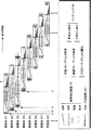
図13は、基板接合装置100の高温部99における複数の積層体401〜408の熱履歴を示すダイアグラムである。図示のように、高温部99には、複数の積層体401〜408が順次搬入され、次々に本接合される。   FIG. 13 is a diagram illustrating the thermal history of the multiple stacked bodies 401 to 408 in the high temperature part 99 of the substrate bonding apparatus 100. As shown in the drawing, a plurality of laminated bodies 401 to 408 are sequentially carried into the high temperature part 99 and are finally joined one after another.

図1および図2に示した基板接合装置100の高温部99には、単独の処理時間が最も長い加熱加圧装置170が3基配される。一方、搬送時間が短い環境ローダ160と単独の処理時間が短い冷却装置180とは、それぞれ1基ずつが高温部99に配される。   In the high temperature part 99 of the substrate bonding apparatus 100 shown in FIGS. 1 and 2, three heating and pressing apparatuses 170 having the longest single processing time are arranged. On the other hand, one environmental loader 160 having a short conveyance time and one cooling device 180 having a short processing time are arranged in the high temperature part 99.

このため、図示のように、複数の積層体106を搬入された高温部99では、例えば、積層体401が冷却装置180で冷却されている間は、他の積層体402加熱加圧装置170から積層体106を搬出できない。このため、加熱加圧装置170における放冷器官308の長さが変化すると共に、加熱加圧装置170から搬出される積層体402〜408が温度互いに異なる。   For this reason, as shown in the drawing, in the high temperature unit 99 into which the plurality of stacked bodies 106 are carried, for example, while the stacked body 401 is being cooled by the cooling device 180, The laminated body 106 cannot be carried out. For this reason, the length of the cooling organ 308 in the heating / pressurizing device 170 changes, and the laminated bodies 402 to 408 carried out from the heating / pressurizing device 170 have different temperatures.

図示の例では、タイミングAに最初に高温部99に搬入された積層体401は、放冷期間308無しに冷却装置180に搬送される。このため、加熱加圧装置170から冷却装置180までの搬送期間309は、高温状態の積層体401が搬送される。従って、搬送期間309に積層体401を支持するフォーク162、262は、より温度の高いものが選択される。   In the example shown in the figure, the stacked body 401 first carried into the high temperature unit 99 at the timing A is transported to the cooling device 180 without the cooling period 308. For this reason, in the conveyance period 309 from the heating / pressurizing device 170 to the cooling device 180, the high-temperature laminate 401 is conveyed. Accordingly, the forks 162 and 262 that support the stacked body 401 during the conveyance period 309 are selected to have higher temperatures.

タイミングBに2番目に搬入される積層体402は、積層体401が搬出された後に直ちに給気されたロードロック150に搬入される。ロードロック150から加熱加圧装置170に搬入された積層体402は直ちに加熱加圧されて本接合される。しかしながら、加熱および加圧が終了した後は、冷却装置180が積層体401の冷却から開放されるまで、積層体402を格納して放冷させる。このため、積層体402の温度は徐々に降下するが、冷却装置180に搬入される時点では依然として高温状態にある。   The stacked body 402 that is transported second at the timing B is transported to the load lock 150 that is supplied with air immediately after the stacked body 401 is unloaded. The laminated body 402 carried into the heating / pressurizing device 170 from the load lock 150 is immediately heated and pressurized and finally joined. However, after the heating and pressurization are completed, the stacked body 402 is stored and allowed to cool until the cooling device 180 is released from the cooling of the stacked body 401. For this reason, although the temperature of the laminated body 402 falls gradually, at the time of carrying in to the cooling device 180, it is still in a high temperature state.

タイミングCに3番目に搬入される積層体403は、積層体402が搬出された後に直ちに給気されたロードロック150に搬入される。ロードロック150が排気された後に加熱加圧装置170に搬入された積層体403は直ちに加熱加圧されて本接合される。しかしながら、積層体401、402からの冷却装置180の開放を待つ時間は重畳され、加熱加圧装置170における放冷器官308は更に長くなる。このため、冷却装置180に搬入される時点では、積層体403は低温状態になる。よって、積層体403の搬送期間309は、低温状態のフォーク162、262により積層体403が支持される。   The stacked body 403 that is transported third at timing C is transported to the load lock 150 that is supplied with air immediately after the stacked body 402 is transported. After the load lock 150 is evacuated, the stacked body 403 carried into the heating / pressurizing device 170 is immediately heated and pressurized and finally joined. However, the time for waiting for the cooling device 180 to be released from the stacked bodies 401 and 402 is overlapped, and the cooling organ 308 in the heating and pressurizing device 170 becomes longer. For this reason, when it carries in to the cooling device 180, the laminated body 403 will be in a low temperature state. Therefore, during the conveyance period 309 of the stacked body 403, the stacked body 403 is supported by the low-temperature forks 162 and 262.

積層体404が搬入されるタイミングDは、加熱加圧装置170による積層体404の本接合が終了した後、比較的短時間で積層体404を冷却装置180に搬入できるように、高温部99に対する搬入時間を遅くしている。これにより、放冷期間308が短縮され、冷却装置180に搬入される積層体404は、高温状態になる。従って、搬送期間309に積層体404を支持するフォークは、高温状態のものが選択される。   The timing D when the laminated body 404 is carried in is such that the laminated body 404 can be carried into the cooling device 180 in a relatively short time after the main joining of the laminated body 404 by the heating and pressurizing device 170 is completed. The delivery time is delayed. Thereby, the cool-down period 308 is shortened, and the laminated body 404 carried into the cooling device 180 is in a high temperature state. Therefore, the fork that supports the stacked body 404 during the conveyance period 309 is selected in a high temperature state.

以下、積層体405以降は、いずれの積層体405、406、407、408に対しても概ね同じシーケンスが実行され、搬送器官309の積層体408はいずれも高温状態となる。よって、搬送期間309は、高温状態のフォーク162、262が繰り返し使用される。このため、高温状態のフォーク162、262の温度も、高温状態で安定する。   Hereinafter, the same sequence is executed for any of the stacked bodies 405, 406, 407, and 408 after the stacked body 405, and all of the stacked bodies 408 of the transport organ 309 are in a high temperature state. Therefore, the forks 162 and 262 in the high temperature state are repeatedly used during the conveyance period 309. For this reason, the temperature of the forks 162 and 262 in the high temperature state is also stable in the high temperature state.

ただし、例えば、基板102を補充する目的でFOUP116を交換するような場合には、基板接合装置100の稼働が中断する。このような場合、当初は高温状態であったフォーク162、262が低温状態に遷移する場合がある。このような状態の変化は、フォーク162、262に設けた測温部161、261を介して制御部114に検知される。   However, for example, when the FOUP 116 is replaced for the purpose of supplementing the substrate 102, the operation of the substrate bonding apparatus 100 is interrupted. In such a case, the forks 162 and 262 that were initially in a high temperature state may transition to a low temperature state. Such a change in state is detected by the control unit 114 via the temperature measuring units 161 and 261 provided on the forks 162 and 262.

なお、上記の例は、一対の基板102を接合する場合に、一対の基板ホルダ104を用いる場合について説明した。しかしながら、基板ホルダ104を用いることなく、基板102を直接に積層して加熱加圧する基板接合装置においても、基板102の温度に応じてフォーク162、262を選択することにより、基板102の位置合わせ精度が維持される。   In the above example, the case where the pair of substrate holders 104 is used when the pair of substrates 102 are bonded has been described. However, even in a substrate bonding apparatus that directly stacks and heat-presses the substrate 102 without using the substrate holder 104, the alignment accuracy of the substrate 102 is selected by selecting the forks 162 and 262 according to the temperature of the substrate 102. Is maintained.

以上、本発明を実施の形態を用いて説明したが、本発明の技術的範囲は上記実施の形態に記載の範囲には限定されない。上記実施の形態に、多様な変更または改良を加えることが可能であることが当業者に明らかである。その様な変更または改良を加えた形態も本発明の技術的範囲に含まれ得ることが、特許請求の範囲の記載から明らかである。   As mentioned above, although this invention was demonstrated using embodiment, the technical scope of this invention is not limited to the range as described in the said embodiment. It will be apparent to those skilled in the art that various modifications or improvements can be added to the above-described embodiment. It is apparent from the scope of the claims that the embodiments added with such changes or improvements can be included in the technical scope of the present invention.

特許請求の範囲、明細書、および図面中において示した装置、システム、プログラム、および方法における動作、手順、ステップ、および段階等の各処理の実行順序は、特段「より前に」、「先立って」等と明示しておらず、また、前の処理の出力を、後の処理で用いる場合でない限り、任意の順序で実現しうることに留意されたい。特許請求の範囲、明細書、および図面中の動作フローに関して、便宜上「まず、」、「次に、」等を用いて説明したとしても、この順で実施することが必須であることを意味するものではない。   The order of execution of each process such as operations, procedures, steps, and stages in the apparatus, system, program, and method shown in the claims, the description, and the drawings is particularly “before” or “prior to”. It should be noted that the output of the previous process may be realized in any order unless used in a subsequent process. Regarding the operation flow in the claims, the description, and the drawings, even if it is described using “first”, “next”, etc. for convenience, it means that it is essential to carry out in this order. It is not a thing.

98 室温部、99 高温部、100 基板接合装置、101 溝、102 基板、103 クリップ、104 基板ホルダ、106、401、402、403、404、405、406、407、408 積層体、108 積層型基板、110 筐体、112 断熱壁、114 制御部、116 FOUP、118 真空ポンプ、120 大気ローダ、121 ガイドレール、122、162、262 フォーク、124、164、264 アーム、126、166 フォールディングアーム、130 アライナ、131 駆動部、132 フレーム、134 下ステージ、136 上ステージ、138 防振脚、142 基板プリアライナ、144 ホルダプリアライナ、146 ホルダストッカ、150 ロードロック、152、154 シャッタ、156 気密壁、160 環境ローダ、161、261 測温部、163 吸着部、165 給電部、168 共通支持部、169 支柱、170 加圧装置、171、181 搬入口、172、182 シリンダ、173、183 ピストン、174、184 冷却プレート、175、185 冷媒路、176 加熱プレート、177 ヒータ、178、188 断熱プレート、179、189 枠体、180 冷却装置、186 弾性支持部 98 Room temperature part, 99 High temperature part, 100 Substrate bonding device, 101 groove, 102 substrate, 103 clip, 104 substrate holder, 106, 401, 402, 403, 404, 405, 406, 407, 408 laminate, 108 laminate substrate , 110 housing, 112 heat insulation wall, 114 control unit, 116 FOUP, 118 vacuum pump, 120 atmospheric loader, 121 guide rail, 122, 162, 262 fork, 124, 164, 264 arm, 126, 166 folding arm, 130 aligner 131 Drive unit 132 Frame 134 Lower stage 136 Upper stage 138 Anti-vibration leg 142 Substrate pre-aligner 144 Holder pre-aligner 146 Holder stocker 150 Load lock 152 152 Shutter 156 Airtight wall, 160 Environmental loader, 161, 261 Temperature measuring unit, 163 Adsorption unit, 165 Power supply unit, 168 Common support unit, 169 Support, 170 Pressurizer, 171, 181 Carriage inlet, 172, 182 Cylinder, 173, 183 Piston 174, 184 Cooling plate, 175, 185 Refrigerant path, 176 Heating plate, 177 Heater, 178, 188 Heat insulation plate, 179, 189 Frame, 180 Cooling device, 186 Elastic support

Claims (26)

互いに位置合わせされて重ね合わされ、それぞれに素子が形成された少なくとも二つの半導体基板を有する積層体を搬送する搬送装置であって、
前記積層体を搭載する複数の搭載部と、
前記積層体の温度を測定する測温部と、
を備え、
前記複数の搭載部のうち、前記積層体の温度に応じて、前記積層体を搭載する搭載部を選択する制御部を備えることを特徴とする搬送装置。
A transport device that transports a stacked body having at least two semiconductor substrates each aligned and superposed, each having an element formed thereon,
A plurality of mounting portions for mounting the laminate;
A temperature measuring unit for measuring the temperature of the laminate;
With
A transport apparatus comprising: a control unit that selects a mounting unit on which the stacked body is mounted according to a temperature of the stacked body among the plurality of mounting units.
前記測温部は、前記複数の搭載部のそれぞれの温度を測定し、
前記制御部は、前記温度と前記積層体の温度との差に応じて、前記搭載部を選択する請求項1に記載の搬送装置。
The temperature measuring unit measures the temperature of each of the plurality of mounting units,
The said control part is a conveying apparatus of Claim 1 which selects the said mounting part according to the difference of the said temperature and the temperature of the said laminated body .
前記制御部は、前記温度と前記積層体の温度との差が小さい前記搭載部を選択する請求項に記載の搬送装置。 The transport apparatus according to claim 2 , wherein the control unit selects the mounting unit having a small difference between the temperature and the temperature of the stacked body . 前記制御部は、前記複数の搭載部のうち前記測温部による測定結果が等しい前記搭載部が複数あった場合、前記半導体基板に対する距離が近いことを条件にして、前記複数の搭載部から使用すべき前記搭載部を選択する請求項2または3に記載の搬送装置。 The control unit is used from the plurality of mounting units on the condition that the distance to the semiconductor substrate is short when there are a plurality of mounting units having the same measurement result by the temperature measuring unit among the plurality of mounting units. conveying apparatus according to claim 2 or 3 selects should do the mounting portion. 前記測温部は、前記搭載部に配された熱電対を含む請求項1から4のいずれか一項に記載の搬送装置。 The said temperature measuring part is a conveying apparatus as described in any one of Claim 1 to 4 containing the thermocouple distribute | arranged to the said mounting part. 前記測温部は、前記搭載部の温度を非接触で測定する請求項1から4のいずれか一項に記載の搬送装置。 The said temperature measurement part is a conveying apparatus as described in any one of Claim 1 to 4 which measures the temperature of the said mounting part by non-contact . 前記測温部は、放射温度計を含む請求項に記載の搬送装置。 The said temperature measurement part is a conveying apparatus of Claim 6 containing a radiation thermometer. 前記制御部は、前記搭載部に搭載される前に前記半導体基板に対して処理された内容に基づいて、前記基板の温度を予測する請求項1から7のいずれか一項に記載の搬送装置。 The transfer device according to any one of claims 1 to 7, wherein the control unit predicts a temperature of the substrate based on content processed on the semiconductor substrate before being mounted on the mounting unit. . 前記制御部は、前記測温部を用いて、前記搭載部に搭載される前記積層体の温度を測定する請求項1から8のいずれか一項に記載の搬送装置。 The said control part is a conveying apparatus as described in any one of Claim 1 to 8 which measures the temperature of the said laminated body mounted in the said mounting part using the said temperature measurement part . 互いに位置合わせされて重ね合され、それぞれに素子が形成された少なくとも二つの半導体基板を有する積層体を搬送する搬送装置であって、
前記積層体を搭載する複数の搭載部と、
前記複数の搭載部の温度を測定する測温部と、
を備え、
記複数の搭載部のうち、前記測温部により測定された前記温度に応じて、前記積層体を搭載する搭載部を選択する制御部を備えることを特徴とする搬送装置。
A transport device that transports a stacked body having at least two semiconductor substrates each aligned and superposed, each having an element formed thereon,
A plurality of mounting portions for mounting the laminate;
A temperature measuring unit for measuring the temperature of the plurality of mounting units ;
With
Among previous SL plurality of mounting portions, the conveying apparatus according to said measured temperature by the temperature measuring unit, characterized in that it comprises a control unit for selecting a mounting portion for mounting the laminate.
前記半導体基板と他の半導体基板とを互いに位置合わせして重ね合わせる位置合わせ部と、
互いに重ね合された前記半導体基板および前記他の半導体基板を搬送する搬送装置と、
前記搬送装置により搬送された前記半導体基板および前記他の半導体基板を互いに接合する接合部と、
を備え、
前記搬送装置は、請求項1から10のいずれか一項に記載の搬送装置である基板接合装置。
An alignment portion for aligning and overlapping the semiconductor substrate and another semiconductor substrate;
A transport device for transporting the semiconductor substrate and the other semiconductor substrate superimposed on each other;
A bonding portion for bonding the semiconductor substrate transferred by the transfer device and the other semiconductor substrate to each other;
With
The said transfer apparatus is a board | substrate joining apparatus which is a transfer apparatus as described in any one of Claim 1 to 10 .
前記接合部は、
真空環境に配され、前記半導体基板および前記他の半導体基板を加熱する加熱装置と、
前記真空環境を大気環境と結合し、加熱された前記半導体基板および前記他の半導体基板、および、加熱される前の前記半導体基板および前記他の半導体基板がそれぞれ配置されるロードロックと、を有し、
前記搬送装置は、前記加熱装置前記ロードロックの間で前記半導体基板および前記他の半導体基板を搬送する請求項11に記載の基板接合装置。
The joint is
A heating device arranged in a vacuum environment and heating the semiconductor substrate and the other semiconductor substrate;
The vacuum environment is combined with an atmospheric environment, and the heated semiconductor substrate and the other semiconductor substrate, and the load lock on which the semiconductor substrate and the other semiconductor substrate before being heated are respectively disposed. And
The transfer device, the heating device and a substrate bonding apparatus according to claim 11 for transferring the semiconductor substrate and the other semiconductor substrate between said load lock.
前記接合部は、前記加熱装置により加熱された前記半導体基板および前記他の半導体基板を冷却する冷却装置を有し、
前記搬送装置は、前記加熱装置、前記冷却装置、および、前記ロードロックの間で前記半導体基板および前記他の半導体基板を搬送する請求項12に記載の基板接合装置。
The joint has a cooling device that cools the semiconductor substrate heated by the heating device and the other semiconductor substrate,
13. The substrate bonding apparatus according to claim 12 , wherein the transfer device transfers the semiconductor substrate and the other semiconductor substrate between the heating device, the cooling device, and the load lock.
互いに位置合わせされて重ね合されてそれぞれに素子が形成された少なくとも二つの半導体基板を有する積層体を保持する基板保持部材を搬送する搬送装置であって、
前記積層体および前記基板保持部材を搭載する複数の搭載部と、
前記積層体または前記基板保持部材の温度を測定する測温部と、
を備え、
前記複数の搭載部のうち、前記測温部により測定された前記温度に応じて、前記基板保持部材を搭載する搭載部を選択する制御部を備えることを特徴とする搬送装置。
A transport device that transports a substrate holding member that holds a stacked body having at least two semiconductor substrates that are aligned and overlapped with each other and each of which has an element formed thereon,
A plurality of mounting portions for mounting the laminate and the substrate holding member ;
A temperature measuring unit for measuring the temperature of the laminate or the substrate holding member ;
With
A transport apparatus comprising: a control unit that selects a mounting unit on which the substrate holding member is mounted according to the temperature measured by the temperature measuring unit among the plurality of mounting units.
前記測温部は、前記複数の搭載部のそれぞれの温度を測定し、
前記制御部は、前記複数の搭載部のうち、前記温度と前記積層体または前記基板保持部材の温度との差に応じて、前記搭載部を選択する請求項14に記載の搬送装置。
The temperature measuring unit measures the temperature of each of the plurality of mounting units,
The transfer device according to claim 14 , wherein the control unit selects the mounting unit according to a difference between the temperature and the temperature of the stacked body or the substrate holding member among the plurality of mounting units.
前記測温部は、前記複数の搭載部のそれぞれの温度を測定し、
前記制御部は、前記複数の搭載部のうち、前記温度と前記積層体または前記基板保持部材の温度との差が小さい前記搭載部を選択する請求項15に記載の搬送装置。
The temperature measuring unit measures the temperature of each of the plurality of mounting units,
The transfer device according to claim 15 , wherein the control unit selects the mounting unit having a small difference between the temperature and the temperature of the stacked body or the substrate holding member among the plurality of mounting units.
前記制御部は、前記複数の搭載部のうち前記測温部による測定結果が等しい前記搭載部が複数あった場合、前記基板保持部材に対する距離が近いことを条件にして、前記複数の搭載部から使用すべき前記搭載部を選択する請求項15または16に記載の搬送装置。 Wherein, when said mounting portion measurement result is equal by the temperature measuring unit of the plurality of mounting portions are a plurality, in the condition that the distance is closer to said substrate holding member, from the plurality of mounting portions The transport apparatus according to claim 15 or 16 , wherein the mounting unit to be used is selected. 前記測温部は、前記搭載部に配された熱電対を含む請求項15から17のいずれか一項に記載の搬送装置。 The said temperature measurement part is a conveying apparatus as described in any one of Claims 15 to 17 containing the thermocouple distribute | arranged to the said mounting part. 前記測温部は、前記搭載部の温度を非接触で測定する請求項15から17のいずれか一項に記載の搬送装置。 The said temperature measurement part is a conveying apparatus as described in any one of Claims 15-17 which measures the temperature of the said mounting part by non-contact . 前記測温部は、放射温度計を含む請求項19に記載の搬送装置。 The transport device according to claim 19 , wherein the temperature measuring unit includes a radiation thermometer. 前記制御部は、前記搭載部に搭載される前に前記半導体基板に対して処理された内容に基づいて、前記基板保持部材の温度を予測する請求項15から20のいずれか一項に記載の搬送装置。 The control unit, on the basis of the contents processed for the semiconductor substrate before being mounted on the mounting portion, according to any one of claims 15 to 20 for predicting the temperature of the substrate holding member Conveying device. 前記制御部は、前記測温部を用いて、前記搭載部に搭載される前記基板保持部材の温度を測定する請求項15から21のいずれか一項に記載の搬送装置。 The said control part is a conveying apparatus as described in any one of Claim 15 to 21 which measures the temperature of the said board | substrate holding member mounted in the said mounting part using the said temperature measurement part . 素子が形成された半導体基板を保持する基板保持部材を搬送する搬送装置であって、
前記半導体基板が保持された基板保持部材を搭載する複数の搭載部と、
前記複数の搭載部の温度を測定する測温部と、
前記複数の搭載部のうち、前記測温部により測定された前記温度に応じて、前記基板保持部を搭載する搭載部を選択する制御部を備えることを特徴とする搬送装置。
A transport device that transports a substrate holding member that holds a semiconductor substrate on which an element is formed,
A plurality of mounting portions for mounting a substrate holding member on which the semiconductor substrate is held;
A temperature measuring unit for measuring the temperature of the plurality of mounting units;
A transport apparatus comprising: a control unit that selects a mounting unit on which the substrate holding unit is mounted according to the temperature measured by the temperature measuring unit among the plurality of mounting units.
前記基板保持部材に保持された前記半導体基板と他の半導体基板とを互いに位置合わせして重ね合わせる位置合わせ部と、
互いに重ね合された前記半導体基板および前記他の半導体基板を前記基板保持部材に保持した状態で搬送する搬送装置と、
前記搬送装置により搬送された前記半導体基板および前記他の半導体基板を前記基板保持部材により保持された状態で互いに接合する接合部と、
を備え、
前記搬送装置は、請求項15から23のいずれか一項に記載の搬送装置である基板接合装置。
An alignment portion that aligns and superimposes the semiconductor substrate held by the substrate holding member and another semiconductor substrate;
A transport device for transporting the semiconductor substrate and the other semiconductor substrate stacked on each other while being held by the substrate holding member;
A bonding portion that bonds the semiconductor substrate transferred by the transfer device and the other semiconductor substrate to each other while being held by the substrate holding member;
With
24. The substrate bonding apparatus, which is the transfer apparatus according to any one of claims 15 to 23 .
前記接合部は、
真空環境に配され、前記半導体基板および前記他の半導体基板を前記基板保持部材に保持した状態で加熱する加熱装置と、
前記真空環境を大気環境と結合し、加熱された前記半導体基板および前記他の半導体基板、および、加熱される前の前記半導体基板および前記他の半導体基板がそれぞれ配置されるロードロックと、を有し、
前記搬送装置は、前記加熱装置前記ロードロックの間で前記半導体基板および前記他の半導体基板を前記基板保持部材に保持した状態で搬送する請求項24に記載の基板接合装置。
The joint is
A heating device that is arranged in a vacuum environment and heats the semiconductor substrate and the other semiconductor substrate while being held by the substrate holding member ;
The vacuum environment is combined with an atmospheric environment, and the heated semiconductor substrate and the other semiconductor substrate, and the load lock on which the semiconductor substrate and the other semiconductor substrate before being heated are respectively disposed. And
The transport apparatus, a substrate bonding device according to claim 24, conveyed in a state where the semiconductor substrate and the other semiconductor substrate held in the substrate holding member between said load lock and said heating device.
前記接合部は、前記加熱装置により加熱された前記半導体基板および前記他の半導体基板を前記基板保持部材に保持した状態で冷却する冷却装置を有し、
前記搬送装置は、前記加熱装置、前記冷却装置、および、前記ロードロックの間で前記半導体基板および前記他の半導体基板を前記基板保持部材に保持した状態で搬送する請求項25に記載の基板接合装置。
The bonding portion has a cooling device that cools the semiconductor substrate heated by the heating device and the other semiconductor substrate while being held by the substrate holding member,
26. The substrate bonding according to claim 25 , wherein the transfer device transfers the semiconductor substrate and the other semiconductor substrate between the heating device, the cooling device, and the load lock while being held by the substrate holding member. apparatus.
JP2010040111A 2010-02-25 2010-02-25 Conveying apparatus and substrate bonding apparatus Active JP5387444B2 (en)

Priority Applications (1)

Application Number Priority Date Filing Date Title
JP2010040111A JP5387444B2 (en) 2010-02-25 2010-02-25 Conveying apparatus and substrate bonding apparatus

Applications Claiming Priority (1)

Application Number Priority Date Filing Date Title
JP2010040111A JP5387444B2 (en) 2010-02-25 2010-02-25 Conveying apparatus and substrate bonding apparatus

Publications (3)

Publication Number Publication Date
JP2011176197A JP2011176197A (en) 2011-09-08
JP2011176197A5 JP2011176197A5 (en) 2013-07-25
JP5387444B2 true JP5387444B2 (en) 2014-01-15

Family

ID=44688784

Family Applications (1)

Application Number Title Priority Date Filing Date
JP2010040111A Active JP5387444B2 (en) 2010-02-25 2010-02-25 Conveying apparatus and substrate bonding apparatus

Country Status (1)

Country Link
JP (1) JP5387444B2 (en)

Families Citing this family (6)

* Cited by examiner, † Cited by third party
Publication number Priority date Publication date Assignee Title
US9442482B2 (en) 2013-04-29 2016-09-13 GlobalFoundries, Inc. System and method for monitoring wafer handling and a wafer handling machine
JP2020017645A (en) * 2018-07-26 2020-01-30 株式会社Kokusai Electric Substrate processing apparatus
JP7175151B2 (en) * 2018-09-28 2022-11-18 東京エレクトロン株式会社 Conveying method
CN113543920B (en) * 2019-03-14 2023-04-11 东京毅力科创株式会社 Joining system and joining method
JPWO2022196063A1 (en) * 2021-03-15 2022-09-22
WO2023139937A1 (en) * 2022-01-19 2023-07-27 東京エレクトロン株式会社 Substrate conveyance system

Family Cites Families (2)

* Cited by examiner, † Cited by third party
Publication number Priority date Publication date Assignee Title
JP2008288506A (en) * 2007-05-21 2008-11-27 Nikon Corp Adjusting method, exposure apparatus, and device manufacturing method
JP2009182235A (en) * 2008-01-31 2009-08-13 Tokyo Electron Ltd Load lock apparatus and substrate cooling method

Also Published As

Publication number Publication date
JP2011176197A (en) 2011-09-08

Similar Documents

Publication Publication Date Title
JP5387444B2 (en) Conveying apparatus and substrate bonding apparatus
JP5549344B2 (en) Substrate bonding apparatus, substrate holder, substrate bonding method, device manufacturing method, and alignment apparatus
EP2939265B1 (en) Wafer level packaging of microbolometer vacuum package assemblies
KR101860956B1 (en) Pair of substrate holders, method for manufacturing device, separation device, method for separating substrates, substrate holder, and device for positioning substrate
JP5417751B2 (en) Joining apparatus and joining method
JP5314607B2 (en) Joining apparatus, joining method, program, and computer storage medium
JP2010114208A (en) Cooling apparatus and joining system
JP5754261B2 (en) Substrate laminating apparatus, substrate laminating method, and manufacturing method of laminated semiconductor device
JP5459025B2 (en) Substrate laminating apparatus, laminated semiconductor device manufacturing method, laminated semiconductor device, substrate laminating method, and laminated semiconductor device manufacturing method
JP5447110B2 (en) Substrate laminating apparatus, laminated semiconductor manufacturing method, laminated semiconductor, and substrate laminating method
JP5630020B2 (en) Substrate overlay apparatus and overlay method
JP5476705B2 (en) Multilayer semiconductor manufacturing apparatus, multilayer semiconductor manufacturing method, and substrate holder rack
JP5552826B2 (en) Substrate laminating apparatus, laminated semiconductor device manufacturing method, and laminated semiconductor device
JP5487741B2 (en) Substrate bonding equipment
JP2012054416A (en) Pressing device, lamination apparatus, lamination method, and method of manufacturing multilayer semiconductor device
JP5780002B2 (en) Substrate bonding apparatus and substrate bonding method
JP6492528B2 (en) Heating apparatus, substrate bonding apparatus, heating method, and manufacturing method of laminated semiconductor device
JP5569169B2 (en) Substrate bonding apparatus control method, substrate bonding apparatus, laminated semiconductor device manufacturing method, and laminated semiconductor apparatus
JP5323730B2 (en) Joining apparatus, joining method, program, and computer storage medium
JP5487740B2 (en) Overlay apparatus, alignment apparatus, substrate bonding apparatus, and overlay method
JP5487739B2 (en) Substrate bonding apparatus and substrate bonding method
JP2014075589A (en) Substrate bonding apparatus and substrate bonding method
JP5557170B2 (en) Wafer bonding apparatus and wafer bonding method
JP2012104517A (en) Substrate bonding device, laminated semiconductor device manufacturing method, and laminated semiconductor device
JP2010287692A (en) Substrate cover

Legal Events

Date Code Title Description
A621 Written request for application examination

Free format text: JAPANESE INTERMEDIATE CODE: A621

Effective date: 20130222

A521 Request for written amendment filed

Free format text: JAPANESE INTERMEDIATE CODE: A523

Effective date: 20130606

TRDD Decision of grant or rejection written
A01 Written decision to grant a patent or to grant a registration (utility model)

Free format text: JAPANESE INTERMEDIATE CODE: A01

Effective date: 20130910

A61 First payment of annual fees (during grant procedure)

Free format text: JAPANESE INTERMEDIATE CODE: A61

Effective date: 20130923

R150 Certificate of patent or registration of utility model

Ref document number: 5387444

Country of ref document: JP

Free format text: JAPANESE INTERMEDIATE CODE: R150

Free format text: JAPANESE INTERMEDIATE CODE: R150

R250 Receipt of annual fees

Free format text: JAPANESE INTERMEDIATE CODE: R250

R250 Receipt of annual fees

Free format text: JAPANESE INTERMEDIATE CODE: R250

R250 Receipt of annual fees

Free format text: JAPANESE INTERMEDIATE CODE: R250

R250 Receipt of annual fees

Free format text: JAPANESE INTERMEDIATE CODE: R250

R250 Receipt of annual fees

Free format text: JAPANESE INTERMEDIATE CODE: R250

R250 Receipt of annual fees

Free format text: JAPANESE INTERMEDIATE CODE: R250

R250 Receipt of annual fees

Free format text: JAPANESE INTERMEDIATE CODE: R250

R250 Receipt of annual fees

Free format text: JAPANESE INTERMEDIATE CODE: R250