JP6492528B2 - Heating apparatus, substrate bonding apparatus, heating method, and manufacturing method of laminated semiconductor device - Google Patents

Heating apparatus, substrate bonding apparatus, heating method, and manufacturing method of laminated semiconductor device Download PDF

Info

Publication number
JP6492528B2
JP6492528B2 JP2014216510A JP2014216510A JP6492528B2 JP 6492528 B2 JP6492528 B2 JP 6492528B2 JP 2014216510 A JP2014216510 A JP 2014216510A JP 2014216510 A JP2014216510 A JP 2014216510A JP 6492528 B2 JP6492528 B2 JP 6492528B2
Authority
JP
Japan
Prior art keywords
substrate
heating
substrates
unit
temperature
Prior art date
Legal status (The legal status is an assumption and is not a legal conclusion. Google has not performed a legal analysis and makes no representation as to the accuracy of the status listed.)
Active
Application number
JP2014216510A
Other languages
Japanese (ja)
Other versions
JP2016086037A5 (en
JP2016086037A (en
Inventor
菅谷 功
功 菅谷
Current Assignee (The listed assignees may be inaccurate. Google has not performed a legal analysis and makes no representation or warranty as to the accuracy of the list.)
Nikon Corp
Original Assignee
Nikon Corp
Priority date (The priority date is an assumption and is not a legal conclusion. Google has not performed a legal analysis and makes no representation as to the accuracy of the date listed.)
Filing date
Publication date
Application filed by Nikon Corp filed Critical Nikon Corp
Priority to JP2014216510A priority Critical patent/JP6492528B2/en
Publication of JP2016086037A publication Critical patent/JP2016086037A/en
Publication of JP2016086037A5 publication Critical patent/JP2016086037A5/ja
Application granted granted Critical
Publication of JP6492528B2 publication Critical patent/JP6492528B2/en
Active legal-status Critical Current
Anticipated expiration legal-status Critical

Links

Images

Landscapes

  • Container, Conveyance, Adherence, Positioning, Of Wafer (AREA)

Description

本発明は、加熱装置、基板接合装置、加熱方法および積層半導体装置の製造方法に関する。   The present invention relates to a heating apparatus, a substrate bonding apparatus, a heating method, and a method for manufacturing a laminated semiconductor device.

複数の基板を積層して加熱することにより積層構造の基板を製造する加熱加圧装置がある(例えば、特許文献1参照)。
特許文献1 特開2008−282857号公報
There is a heating and pressing apparatus that manufactures a substrate having a laminated structure by laminating and heating a plurality of substrates (for example, see Patent Document 1).
Japanese Patent Application Laid-Open No. 2008-282857

加熱装置において生じる基板相互の位置ずれにより積層基板の製造歩留りが低下する場合がある。   There may be a case where the manufacturing yield of the laminated substrate is lowered due to the positional deviation between the substrates which occurs in the heating device.

本発明の第1態様によると、第1の基板および第2の基板の少なくとも一方を加熱する加熱部と、位置合わせした第1の基板および第2の基板の位置関係を維持すべく、第1の基板および第2の基板の少なくとも一方の温度を制御する制御部とを備える加熱装置が提供される。   According to the first aspect of the present invention, the heating unit that heats at least one of the first substrate and the second substrate and the positional relationship between the aligned first substrate and second substrate are maintained. And a controller that controls the temperature of at least one of the substrate and the second substrate.

本発明の第2態様によると、第1の基板および第2の基板の少なくとも一方を加熱する加熱部と、第1の基板および第2の基板の少なくとも一方における熱膨張による、第1の基板および第2の基板の相互の位置ずれが予め定めた閾値を超える前に、第1の基板上記の加熱装置のいずれかと、第1の基板および第2の基板を位置合わせ装置から搬出して加熱装置に搬入する搬送ロボットとを備える基板接合装置が提供される。   According to the second aspect of the present invention, the heating unit that heats at least one of the first substrate and the second substrate, the first substrate by thermal expansion in at least one of the first substrate and the second substrate, and Before the mutual displacement of the second substrate exceeds a predetermined threshold value, the first substrate and any one of the heating devices described above, the first substrate and the second substrate are unloaded from the alignment device, and the heating device There is provided a substrate bonding apparatus including a transfer robot for carrying in the apparatus.

本発明の第3態様によると、第1の基板および第2の基板を相互に位置合わせする位置合わせ装置と、上記のいずれかの加熱装置と、第1の基板および第2の基板を位置合わせ装置から搬出して加熱装置に搬入する搬送ロボットとを備える基板接合装置が提供される。   According to the third aspect of the present invention, the alignment device for aligning the first substrate and the second substrate with each other, any of the heating devices described above, and the alignment of the first substrate and the second substrate. There is provided a substrate bonding apparatus including a transfer robot that is unloaded from the apparatus and loaded into a heating apparatus.

本発明の第4態様によると、第1の基板および第2の基板の少なくとも一方を加熱する加熱段階と、位置合わせした第1の基板および第2の基板の位置関係を維持すべく、第1の基板および第2の基板の少なくとも一方の温度を制御する制御段階とを備える加熱方法が提供される。   According to the fourth aspect of the present invention, the heating step of heating at least one of the first substrate and the second substrate, and the positional relationship between the aligned first substrate and second substrate are maintained. And a control step for controlling the temperature of at least one of the substrate and the second substrate.

本発明の第5態様によると、第1の基板および第2の基板の少なくとも一方を加熱する加熱段階と、第1の基板および第2の基板の少なくとも一方の熱変形によって生じる第1の基板および第2の基板の相互の位置ずれが予め定めた条件を満たす前に、第1の基板および第2の基板の所定の位置関係を維持する加圧力で、互いに重ね合わされた第1の基板および第2の基板を加圧する加圧段階とを備える加熱方法が提供される。   According to the fifth aspect of the present invention, a heating step of heating at least one of the first substrate and the second substrate, a first substrate generated by thermal deformation of at least one of the first substrate and the second substrate, and Before the mutual displacement of the second substrate satisfies a predetermined condition, the first substrate and the second substrate overlapped with each other with a pressurizing force that maintains a predetermined positional relationship between the first substrate and the second substrate. And a pressing step of pressing the two substrates.

本発明の第6態様によると、第1の基板および第2の基板を位置合わせする位置合わせ段階と、第1の基板および第2の基板の少なくとも一方を加熱する加熱段階と、位置合わせした第1の基板および第2の基板の位置関係を維持すべく、第1の基板および第2の基板の少なくとも一方の温度を制御する制御段階とを備える積層半導体装置の製造方法が提供される。   According to the sixth aspect of the present invention, the alignment step of aligning the first substrate and the second substrate, the heating step of heating at least one of the first substrate and the second substrate, and the aligned first step In order to maintain the positional relationship between one substrate and the second substrate, there is provided a method for manufacturing a stacked semiconductor device, comprising a control step of controlling the temperature of at least one of the first substrate and the second substrate.

本発明の第7態様によると、第1の基板および第2の基板を位置合わせする位置合わせ段階と、第1の基板および第2の基板の少なくとも一方を加熱する加熱段階と、第1の基板および第2の基板の少なくとも一方の熱膨張による相互の位置ずれが予め定めた閾値を超える前に、第1の基板および第2の基板の位置ずれを防止する加圧力で、互いに重ね合わされた第1の基板および第2の基板を加圧する加圧段階とを備える積層半導体装置の製造方法が提供される。   According to a seventh aspect of the present invention, an alignment step of aligning the first substrate and the second substrate, a heating step of heating at least one of the first substrate and the second substrate, and the first substrate Before the mutual displacement due to thermal expansion of at least one of the second substrate and the second substrate exceeds a predetermined threshold, the first substrate and the second substrate overlap each other with a pressurizing force that prevents the displacement of the first substrate and the second substrate. There is provided a method of manufacturing a laminated semiconductor device comprising a pressing step of pressing a first substrate and a second substrate.

上記の発明の概要は、本発明の特徴の全てを列挙したものではない。これらの特徴群のサブコンビネーションもまた、発明となり得る。   The above summary of the present invention does not enumerate all of the features of the present invention. A sub-combination of these feature groups can also be an invention.

基板接合装置100の模式的平面図である。1 is a schematic plan view of a substrate bonding apparatus 100. FIG. 基板ホルダ201の斜視図である。2 is a perspective view of a substrate holder 201. FIG. 基板ホルダ202の斜視図である。5 is a perspective view of a substrate holder 202. FIG. 積層体102の模式的断面図である。3 is a schematic cross-sectional view of a laminated body 102. FIG. 加熱装置300の模式的断面図である。2 is a schematic cross-sectional view of a heating device 300. FIG. 加熱装置300の模式的断面図である。2 is a schematic cross-sectional view of a heating device 300. FIG. 加熱装置300の模式的断面図である。2 is a schematic cross-sectional view of a heating device 300. FIG. 加熱装置300の模式的断面図である。2 is a schematic cross-sectional view of a heating device 300. FIG. 加熱装置300の模式的断面図である。2 is a schematic cross-sectional view of a heating device 300. FIG. 加熱装置300の模式的断面図である。2 is a schematic cross-sectional view of a heating device 300. FIG. 加熱装置300の模式的断面図である。2 is a schematic cross-sectional view of a heating device 300. FIG. 加熱装置300の模式的断面図である。2 is a schematic cross-sectional view of a heating device 300. FIG. 積層基板103の模式的断面図である。3 is a schematic cross-sectional view of a laminated substrate 103. FIG. 積層体102の温度変化を模式的に示すグラフである。3 is a graph schematically showing a temperature change of a laminated body 102. ヒータプレート332、362の温度変化を模式的に示すグラフである。It is a graph which shows typically the temperature change of heater plates 332 and 362. 加熱装置301の模式的断面図である。FIG. 3 is a schematic cross-sectional view of a heating device 301. 加熱装置302の模式的断面図である。3 is a schematic cross-sectional view of a heating device 302. FIG. 加熱装置302の模式的断面図である。3 is a schematic cross-sectional view of a heating device 302. FIG. 加熱装置302の模式的断面図である。3 is a schematic cross-sectional view of a heating device 302. FIG. 積層体102の温度変化を模式的に示すグラフである。3 is a graph schematically showing a temperature change of a laminated body 102. 積層体102の温度変化を模式的に示すグラフである。3 is a graph schematically showing a temperature change of a laminated body 102. 加熱装置303の模式的断面図である。3 is a schematic cross-sectional view of a heating device 303. FIG. 加熱装置304の模式的断面図である。2 is a schematic cross-sectional view of a heating device 304. FIG. 加熱装置305の模式的断面図である。It is a typical sectional view of heating device 305.

発明の実施の形態を通じて本発明を説明する。下記の実施形態は特許請求の範囲に係る発明を限定しない。実施形態の中で説明されている特徴の組み合わせの全てが発明の解決手段に必須であるとは限らない。   The present invention will be described through embodiments of the invention. The following embodiments do not limit the invention according to the claims. Not all combinations of features described in the embodiments are essential for the solution of the invention.

図1は、基板接合装置100の模式的平面図である。基板接合装置100は、筐体110と、筐体110の外面に配された基板カセット120、130および制御部170と、筐体110の内部に配された搬送ロボット140、アライナ150および加熱装置300とを備える。   FIG. 1 is a schematic plan view of the substrate bonding apparatus 100. The substrate bonding apparatus 100 includes a housing 110, substrate cassettes 120 and 130 and a control unit 170 disposed on the outer surface of the housing 110, a transport robot 140, an aligner 150, and a heating device 300 disposed in the housing 110. With.

一方の基板カセット120は、貼り合わせに供する基板101を格納する。基板101は、シリコンウエハ、化合物半導体ウエハ等の半導体基板の他、ガラス基板、サファイア基板等の誘電体基板であってもよい。また、基板101は、素子、回路、端子等が形成されたものでもあってもよい。更に、基板101として、それ自体が既に基板101を積層して接合された積層基板であってもよい。   One substrate cassette 120 stores a substrate 101 to be bonded. The substrate 101 may be a dielectric substrate such as a glass substrate or a sapphire substrate in addition to a semiconductor substrate such as a silicon wafer or a compound semiconductor wafer. Further, the substrate 101 may be one on which elements, circuits, terminals, and the like are formed. Further, the substrate 101 may be a laminated substrate that is already laminated and bonded.

他方の基板カセット130は、基板接合装置100において基板101を貼り合わせて作製した積層基板103を格納する。基板カセット120、130は、筐体110に対して個別に着脱できる。よって、基板カセット120を用いることにより、複数の基板101を基板接合装置100に対して一括して搬入できる。また、基板カセット130を用いることにより、複数の積層基板103を基板接合装置100から一括して搬出できる。   The other substrate cassette 130 stores the laminated substrate 103 produced by bonding the substrates 101 in the substrate bonding apparatus 100. The substrate cassettes 120 and 130 can be individually attached to and detached from the housing 110. Therefore, by using the substrate cassette 120, a plurality of substrates 101 can be carried into the substrate bonding apparatus 100 at a time. Further, by using the substrate cassette 130, a plurality of laminated substrates 103 can be unloaded from the substrate bonding apparatus 100 at a time.

搬送ロボット140は、筐体110の内部において、基板101を、基板カセット120からアライナ150に搬送する。また、搬送ロボット140は、アライナ150にて基板101を重ね合わせて形成された積層体102を加熱装置300に搬送する。更に、搬送ロボット140は、加熱装置300において基板101を接合して形成された積層基板103を、加熱装置300から基板カセット130に搬送する。   The transfer robot 140 transfers the substrate 101 from the substrate cassette 120 to the aligner 150 inside the housing 110. Further, the transfer robot 140 transfers the laminated body 102 formed by stacking the substrates 101 by the aligner 150 to the heating apparatus 300. Further, the transfer robot 140 transfers the laminated substrate 103 formed by bonding the substrates 101 in the heating device 300 to the substrate cassette 130 from the heating device 300.

アライナ150は、それぞれが基板101を保持する一対のステージを有する。一対のステージの各々に基板101を保持させた状態でステージを相対的に移動させることにより、一対の基板101を相互に位置合わせする。更に、位置合わせされた基板101を相互に重ね合わせて、基板101の積層体を形成する。なお、基板接合装置100において、少なくともアライナ150の内部は、室温に近い温度に温度管理される。これにより、アライナ150における基板101位置合わせの精度が維持される。   The aligner 150 has a pair of stages each holding the substrate 101. The pair of substrates 101 are aligned with each other by relatively moving the stage while holding the substrate 101 on each of the pair of stages. Further, the aligned substrates 101 are overlapped with each other to form a stacked body of the substrates 101. In the substrate bonding apparatus 100, at least the inside of the aligner 150 is temperature-controlled at a temperature close to room temperature. Thereby, the accuracy of alignment of the substrate 101 in the aligner 150 is maintained.

加熱装置300は、断熱容器310の内部に形成され、制御部170の制御の下に、搬入された基板101または基板101を含む積層体を加熱する。断熱容器310は、シャッタ320により開閉される開口を有する。これにより、加熱装置300が発生する熱を遮断して、アライナ150の位置合わせ精度が低下することを防止する。なお、加熱装置300は、搬入された基板101または基板101を含む積層体を加熱しつつ加圧する加熱加圧装置であってもよい。また、シャッタ320を閉じた断熱容器310の内部は、基板101の熱酸化等を防止する目的で脱気して、真空環境下で基板101を加熱および加圧してもよい。   The heating device 300 is formed inside the heat insulating container 310 and heats the loaded substrate 101 or the laminated body including the substrate 101 under the control of the control unit 170. The heat insulating container 310 has an opening that is opened and closed by the shutter 320. Thereby, the heat which the heating apparatus 300 generate | occur | produces is interrupted | blocked, and it prevents that the alignment precision of the aligner 150 falls. Note that the heating device 300 may be a heating and pressing device that pressurizes the substrate 101 or the stacked body including the substrate 101 that is carried in while heating. Further, the inside of the heat insulating container 310 with the shutter 320 closed may be deaerated for the purpose of preventing thermal oxidation or the like of the substrate 101, and the substrate 101 may be heated and pressurized in a vacuum environment.

基板101は薄く脆いので、基板接合装置100の内部においては、より高い強度を有する基板ホルダ200に吸着させた状態で基板101を取り扱ってもよい。基板ホルダ200に保持させた状態で基板101を取り扱う場合は、アライナ150において位置合わせ後に形成される積層体が、重ね合わされた基板101を挟む基板ホルダ200を含んでもよい。積層体が基板ホルダ200を含む場合、加熱装置300においては、基板101と共に基板ホルダ200も加熱される。また、加熱装置300において基板101を含む積層体102が加圧される場合は、基板ホルダ200も加圧される。   Since the substrate 101 is thin and fragile, the substrate 101 may be handled inside the substrate bonding apparatus 100 while being adsorbed by the substrate holder 200 having higher strength. When the substrate 101 is handled while being held by the substrate holder 200, the laminate formed after alignment in the aligner 150 may include the substrate holder 200 that sandwiches the stacked substrates 101. When the stacked body includes the substrate holder 200, the substrate holder 200 is also heated together with the substrate 101 in the heating device 300. Further, when the stacked body 102 including the substrate 101 is pressed in the heating apparatus 300, the substrate holder 200 is also pressed.

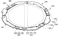
図2は、接合する1対の基板101のうちの一方を保持する基板ホルダ201の斜視図である。図中において、基板ホルダ201は、基板101を保持する保持面212を図中下方に向けた状態で、斜め下方から見上げた状態で示される。基板ホルダ201は、保持部210、枠部220および連結部230を有する。   FIG. 2 is a perspective view of a substrate holder 201 that holds one of a pair of substrates 101 to be joined. In the drawing, the substrate holder 201 is shown in a state in which the holding surface 212 for holding the substrate 101 is directed downward from the lower side in the drawing. The substrate holder 201 includes a holding part 210, a frame part 220, and a connecting part 230.

保持部210は、保持面212、埋設電極214および結合部216を有し、AlNセラミックス等の硬質な材料で一体的に形成される。保持面212は、全体として略円盤状の保持部210において、図中下面に配される。保持面212は、高精度に平坦に成形され、基板101よりも一回り大きな円形をなす。   The holding part 210 has a holding surface 212, an embedded electrode 214, and a coupling part 216, and is integrally formed of a hard material such as AlN ceramics. The holding surface 212 is arranged on the lower surface in the drawing in the generally disc-shaped holding portion 210 as a whole. The holding surface 212 is formed flat with high accuracy and forms a circle that is slightly larger than the substrate 101.

一対の埋設電極214は、保持面212全体を略2つに分配して配置され、互いに絶縁された状態で保持部210の内部に埋設されて、保持部210に静電チャックを形成する。埋設電極214に吸着電圧が印加された場合、絶縁性を有する保持面212に、基板101が静電力により吸着される。   The pair of embedded electrodes 214 are arranged with the entire holding surface 212 divided into two parts, and are embedded in the holding unit 210 while being insulated from each other, thereby forming an electrostatic chuck in the holding unit 210. When an adsorption voltage is applied to the embedded electrode 214, the substrate 101 is adsorbed to the insulating holding surface 212 by electrostatic force.

なお、埋設電極214を含む静電チャックにより発生した静電力は、保持部210の表裏に作用する。よって、埋設電極に吸着電圧が印加された場合、保持面212に対して裏面になる保持部210の図中上面においても静電力が作用する。   The electrostatic force generated by the electrostatic chuck including the embedded electrode 214 acts on the front and back of the holding unit 210. Therefore, when an adsorption voltage is applied to the embedded electrode, an electrostatic force also acts on the upper surface of the holding unit 210 that is the back surface of the holding surface 212 in the drawing.

結合部216は、保持面212の径方向について周縁部から突出して、保持面212の外周に複数箇所配される。結合部216は、保持部210と一体的に形成され、後述する枠部220を保持部210に対して固定する場合にブラケットとして用いられる。   The coupling portions 216 protrude from the peripheral edge in the radial direction of the holding surface 212 and are arranged at a plurality of locations on the outer periphery of the holding surface 212. The coupling portion 216 is formed integrally with the holding portion 210 and is used as a bracket when a frame portion 220 described later is fixed to the holding portion 210.

外部電極228は、フランジ部222の一部において、保持面212と同じ側に複数配される。外部電極228の各々は、埋設電極214のいずれかに電気的に結合される。これにより、外部電極228を通じて、埋設電極214に対して、基板ホルダ201の外部から吸着電圧を印加できる。   A plurality of external electrodes 228 are arranged on the same side as the holding surface 212 in a part of the flange portion 222. Each of external electrodes 228 is electrically coupled to any of buried electrodes 214. Thereby, an adsorption voltage can be applied from the outside of the substrate holder 201 to the embedded electrode 214 through the external electrode 228.

上記のような基板ホルダ201は、半導体ウエハ等の基板101を保持部210の保持面212に載せた状態で、外部電極228を通じて埋設電極214に吸着電圧を印加することにより、基板101を保持面212に吸着させる。これにより、薄くて脆い基板101を、剛性および強度の高い基板ホルダ201と一体的に安全に取り扱うことができる。   The substrate holder 201 as described above applies the adsorption voltage to the embedded electrode 214 through the external electrode 228 while the substrate 101 such as a semiconductor wafer is placed on the holding surface 212 of the holding unit 210, thereby holding the substrate 101 on the holding surface. Adsorb to 212. Thereby, the thin and fragile substrate 101 can be safely handled integrally with the substrate holder 201 having high rigidity and strength.

図3は、接合する1対の基板101の他方を保持する基板ホルダ202の斜視図である。既に説明した基板ホルダ201と共通の要素には、同じ参照番号を付して重複する説明を省く。   FIG. 3 is a perspective view of the substrate holder 202 that holds the other of the pair of substrates 101 to be joined. Elements that are common to the substrate holder 201 already described are denoted by the same reference numerals, and redundant description is omitted.

基板ホルダ202は、基板101を保持する保持面212を図中上方に向けた状態で、斜め上方から見降ろした状態で示される。基板ホルダ202は、保持部210、枠部220および連結部230を有する。基板ホルダ202において、保持部210は、基板ホルダ201の保持部210と同じ構造を有し、保持面212、埋設電極214および結合部216を有する。   The substrate holder 202 is shown in a state where the holding surface 212 for holding the substrate 101 is directed upward in the figure and is looked down obliquely from above. The substrate holder 202 has a holding part 210, a frame part 220 and a connecting part 230. In the substrate holder 202, the holding unit 210 has the same structure as the holding unit 210 of the substrate holder 201, and includes a holding surface 212, an embedded electrode 214, and a coupling unit 216.

保持部210は、保持面212が、図中上面に配されていることを除いて、基板ホルダ201の保持部210と同じ構造を有する。よって、埋設電極214に吸着電圧が印加された場合に、静電力により基板101を保持面212にできる。また、基板ホルダ202においても、埋設電極に吸着電圧が印加された場合、保持面212に対して裏面になる保持部210の図中下面においても静電力が作用する。   The holding unit 210 has the same structure as the holding unit 210 of the substrate holder 201 except that the holding surface 212 is arranged on the upper surface in the drawing. Therefore, when an adsorption voltage is applied to the embedded electrode 214, the substrate 101 can be made the holding surface 212 by electrostatic force. In the substrate holder 202 as well, when an adsorption voltage is applied to the embedded electrode, an electrostatic force acts also on the lower surface in the drawing of the holding unit 210 that is the back surface of the holding surface 212.

基板ホルダ202において、外部電極228は、フランジ部222の一部において、保持面212と反対側に複数配される。外部電極228の各々は、埋設電極214のいずれかに電気的に結合される。これにより、外部電極228を通じて、埋設電極214に対して、基板ホルダ201の外部から吸着電圧を印加できる。   In the substrate holder 202, a plurality of external electrodes 228 are arranged on the side opposite to the holding surface 212 in a part of the flange portion 222. Each of external electrodes 228 is electrically coupled to any of buried electrodes 214. Thereby, an adsorption voltage can be applied from the outside of the substrate holder 201 to the embedded electrode 214 through the external electrode 228.

上記のような基板ホルダ202は、半導体ウエハ等の基板101を保持部210の保持面212に載せた状態で、外部電極228を通じて埋設電極214に吸着電圧を印加することにより、基板101を保持面212に吸着させる。これにより、薄くて脆い基板101を、剛性および強度の高い基板ホルダ201と一体的に安全に取り扱うことができる。   The substrate holder 202 as described above applies the adsorption voltage to the embedded electrode 214 through the external electrode 228 while the substrate 101 such as a semiconductor wafer is placed on the holding surface 212 of the holding unit 210, thereby holding the substrate 101 on the holding surface. Adsorb to 212. Thereby, the thin and fragile substrate 101 can be safely handled integrally with the substrate holder 201 having high rigidity and strength.

図4は、積層体102の模式的断面図である。積層体102は、それぞれが基板ホルダ201、202に保持された一対の基板101を、基板接合装置100のアライナ150により位置合わせして重ね合わせることにより形成される。積層体102においては、一対の基板ホルダ201、202が、吸着部234および被吸着部236により相互に吸着され、アライナ150において基板101が位置合わせされた状態を維持している。   FIG. 4 is a schematic cross-sectional view of the stacked body 102. The stacked body 102 is formed by aligning and overlapping a pair of substrates 101 held by the substrate holders 201 and 202 by the aligner 150 of the substrate bonding apparatus 100. In the stacked body 102, the pair of substrate holders 201 and 202 are adsorbed to each other by the adsorbing unit 234 and the adsorbed unit 236, and the state where the substrate 101 is aligned in the aligner 150 is maintained.

ただし、アライナ150から搬出された段階の積層体102において、一対の基板101はただ重ね合わされているに過ぎず、相互に接合していないか、一部または全体が弱い力で接合している。基板接合装置100の加熱装置300において積層体102が加熱加圧されると、一対の基板101が相互に接合されて一体的な積層基板103となる。   However, in the stacked body 102 at the stage of being unloaded from the aligner 150, the pair of substrates 101 are merely overlapped, and are not bonded to each other, or a part or the whole is bonded with a weak force. When the stacked body 102 is heated and pressurized in the heating device 300 of the substrate bonding apparatus 100, the pair of substrates 101 are bonded to each other to form an integrated stacked substrate 103.

換言するならば、基板接合装置100においては、アライナ150において位置合わせされた一対の基板101の位置関係が、加熱装置300において接合されるまでの間にずれてしまう場合がある。そのような基板101の位置ずれを生じる原因のひとつに、基板101相互の熱膨張量の相違がある。   In other words, in the substrate bonding apparatus 100, the positional relationship between the pair of substrates 101 aligned in the aligner 150 may be shifted before being bonded in the heating apparatus 300. One of the causes of such positional deviation of the substrates 101 is a difference in thermal expansion amount between the substrates 101.

即ち、加熱装置300に搬入された積層体102は、ヒータプレート332、362の少なくとも一方により、厚さ方向外側から加熱される。このため、積層体102における図中下側の基板101は、図中下側のヒータプレート332による加熱の影響を、他方の基板101よりも先に受ける。また、積層体102における図中上側の基板101は、図中上側のヒータプレート362による加熱の影響を、他の基板よりも先に受ける。   That is, the laminate 102 carried into the heating device 300 is heated from the outside in the thickness direction by at least one of the heater plates 332 and 362. For this reason, the lower substrate 101 in the drawing in the laminate 102 is affected by the heating by the lower heater plate 332 in the drawing earlier than the other substrate 101. Further, the upper substrate 101 in the drawing in the laminate 102 is affected by the heating by the upper heater plate 362 in the drawing earlier than the other substrates.

このため、積層体102を形成する一対の基板101間に温度差が生じて、一対の基板101の熱膨張係数が同等である場合には、一対の基板101の面方向および厚さ方向の熱変形量に相違が生じる。ここで、面方向の熱変形には、基板101の面方向に沿った熱膨張及び熱収縮による変形が含まれる。また、厚さ方向の熱変形には、基板101の厚さ方向に沿った熱膨張および熱収縮による変形、および、基板101の撓み変形が含まれる。   For this reason, when a temperature difference arises between a pair of board | substrates 101 which form the laminated body 102, and the thermal expansion coefficient of a pair of board | substrates 101 is equivalent, the heat | fever of the surface direction of a pair of board | substrate 101 and thickness direction is carried out. A difference occurs in the amount of deformation. Here, the thermal deformation in the surface direction includes deformation due to thermal expansion and thermal contraction along the surface direction of the substrate 101. The thermal deformation in the thickness direction includes deformation due to thermal expansion and contraction along the thickness direction of the substrate 101 and bending deformation of the substrate 101.

このため、アライナ150において位置合わせされた基板101の面方向の位置関係および厚さ方向の位置関係の少なくとも一方が、加熱装置300における加熱によりずれてしまう場合がある。また、一対の基板101の熱膨張係数が同等でない場合は、温度差が生じていなくても、一対の基板101の熱変形量に相違が生じ、一対の基板101の面方向および厚さ方向の少なくとも一方の位置関係にずれが生じる。   For this reason, at least one of the positional relationship in the surface direction and the positional relationship in the thickness direction of the substrate 101 aligned in the aligner 150 may be shifted due to heating in the heating device 300. Further, when the thermal expansion coefficients of the pair of substrates 101 are not equal, even if there is no temperature difference, the amount of thermal deformation of the pair of substrates 101 is different, and the surface direction and thickness direction of the pair of substrates 101 are different. A shift occurs in at least one of the positional relationships.

アライナ150で位置合わせされた一対の基板101の位置関係がずれると、一対の基板101のそれぞれに対応して設けられた電極または端子同士の位置関係が維持されずに変化する。また、一対の基板101の熱変形量の相違により、例えば撮像素子の一方の基板に設けられたレンズおよび他方の基板に設けられたフォトダイオードのように位置関係が予め決まっている構造物同士の位置関係が維持されずに変化する。   When the positional relationship between the pair of substrates 101 aligned by the aligner 150 is shifted, the positional relationship between electrodes or terminals provided corresponding to each of the pair of substrates 101 changes without being maintained. Further, due to the difference in the amount of thermal deformation between the pair of substrates 101, for example, between structures having a predetermined positional relationship such as a lens provided on one substrate of an image sensor and a photodiode provided on the other substrate. The positional relationship changes without being maintained.

一対の基板101の熱変形量の差が所定の閾値を超えることにより、位置合わせされた一対の基板101の位置関係が維持されない場合、すなわち、アライナ150で位置合わせされて接触した一対の基板101の電極または端子同士の接触量が所定の大きさ以下になった場合もしくは接触せずに離間した場合、アライナ150で位置合わせされて少なくとも一部が互いに対向した電極または端子同士が部分的にも対向せずに位置ずれした場合、一対の基板101の電極または端子同士がその後の加圧工程での加圧による接触しない程基板101が厚さ方向に変形した場合、および、レンズから出た光がフォトダイオードに入射しない場合、接合された一対の基板101により形成される積層半導体装置に所望の機能が確保されず歩留りが低下する。   When the positional relationship between the aligned pair of substrates 101 is not maintained because the difference in the amount of thermal deformation between the pair of substrates 101 exceeds a predetermined threshold, that is, the pair of substrates 101 that are aligned and contacted by the aligner 150. If the amount of contact between the electrodes or terminals is less than or equal to a predetermined size or is separated without contact, the electrodes or terminals that are aligned by the aligner 150 and at least partially face each other are partially When the position is shifted without facing each other, when the substrate 101 is deformed in the thickness direction so that the electrodes or terminals of the pair of substrates 101 do not come into contact with each other by pressurization in the subsequent pressurization step, and light emitted from the lens Is not incident on the photodiode, a desired function is not ensured in the stacked semiconductor device formed by the pair of bonded substrates 101, and the yield is low. To.

なお、基板101を加圧する前の加熱に時間をかけることにより、一対の基板101間の温度を均衡させることもできるが、その場合は、加熱に要する時間が増加した分、基板接合装置100のスループットが低下する。尚、前記した一対の基板101の電極または端子同士の接触量は、電極または端子の端面の大きさ、および、アライナ150の位置合わせ精度または基板接合装置100の接合精度に基づいて決定される。   Note that although it is possible to balance the temperature between the pair of substrates 101 by taking time before heating the substrate 101, in that case, the amount of time required for the heating increases, Throughput decreases. Note that the amount of contact between the electrodes or terminals of the pair of substrates 101 described above is determined based on the size of the end surfaces of the electrodes or terminals and the alignment accuracy of the aligner 150 or the bonding accuracy of the substrate bonding apparatus 100.

よって、加熱装置300において基板101を接合する場合には、加圧等により最終的に接合する一対の基板101の熱変形量の差が所定の値よりも小さくなっていることが好ましい。逆に、一対の基板101の熱変形量の差によって一対の基板101にずれが生じても、その大きさが、一対の基板101の電極同士が離間せずに接触する範囲内であったり、電極同士が互いに部分的に対向する範囲内であったりすれば、一対の基板101の熱変形量に差が生じてもよい。なお、積層体102を加圧する圧力がある程度上昇した後は、基板101の一方が膨張または収縮しても、基板101の一方が他方に対してずれることがなくなる。   Therefore, when the substrate 101 is bonded in the heating apparatus 300, it is preferable that the difference in the amount of thermal deformation between the pair of substrates 101 to be finally bonded by pressing or the like is smaller than a predetermined value. Conversely, even if the pair of substrates 101 is displaced due to the difference in the amount of thermal deformation between the pair of substrates 101, the size thereof is within a range where the electrodes of the pair of substrates 101 are in contact with each other without being separated, There may be a difference in the amount of thermal deformation between the pair of substrates 101 as long as the electrodes are within a range in which the electrodes partially face each other. Note that after the pressure applied to the stacked body 102 is increased to some extent, even if one of the substrates 101 expands or contracts, one of the substrates 101 does not shift with respect to the other.

また、最終的に基板101の温度が均等になる場合でも、熱変形による基板10の熱履歴が異なると、位置合わせにずれが生じる場合がある。よって、積層体102が加熱装置300に搬入されてから接合に至るまでの過程おいても、基板101相互に生じる温度差が著しく大きくなることは避けることが好ましい。   Further, even when the temperature of the substrate 101 finally becomes equal, if the thermal history of the substrate 10 due to thermal deformation is different, the alignment may be shifted. Therefore, it is preferable to avoid the temperature difference between the substrates 101 from becoming extremely large even in the process from when the stacked body 102 is carried into the heating apparatus 300 to joining.

なお、加熱装置300において処理される積層体102は、図示の構造に限られるわけではない。例えば、基板ホルダ201、202の間で、3枚以上の基板101が重ね合わされている場合もある。また、基板ホルダ201、202の間で重ね合わされた基板101の一方または両方が、既に複数の基板を積層して製造された積層基板103である場合もある。更に、基板ホルダ201、202が取り除かれて、基板101が重ね合わされた状態で加熱加圧される場合もある。   Note that the stacked body 102 processed in the heating apparatus 300 is not limited to the illustrated structure. For example, three or more substrates 101 may be overlapped between the substrate holders 201 and 202. In addition, one or both of the substrates 101 stacked between the substrate holders 201 and 202 may be a stacked substrate 103 that is already manufactured by stacking a plurality of substrates. Furthermore, the substrate holders 201 and 202 may be removed, and the substrate 101 may be heated and pressurized in a state where it is overlapped.

図5および図6は、加熱装置300単独の模式的断面図である。図5は、図6に符号Bで示す、シャッタ320により開閉される搬入口312を有する側壁を切った断面を示す。図6は、図5に符号Aで示す、搬入口312を有していない側壁を切った断面を示す。   5 and 6 are schematic cross-sectional views of the heating device 300 alone. FIG. 5 is a cross-sectional view taken along a side wall having a carry-in port 312 opened and closed by a shutter 320, which is indicated by B in FIG. FIG. 6 shows a cross-sectional view taken along the side wall not having the carry-in port 312, which is indicated by the symbol A in FIG. 5.

加熱装置300は、断熱容器310の内面に形成された仮置台314と、断熱容器310の内部に配された下ステージ330および上ステージ360とを有する。仮置台314は、断熱容器310の側壁内面から、内側に向かって突出して形成される。   The heating apparatus 300 includes a temporary table 314 formed on the inner surface of the heat insulating container 310, and a lower stage 330 and an upper stage 360 disposed inside the heat insulating container 310. The temporary placement table 314 is formed to protrude inward from the inner surface of the side wall of the heat insulating container 310.

仮置台314は、シャッタ320が開いた搬入口312を通じて搬送ロボット140により搬入された積層体102の下面と、略同じ高さの上面を有する。ただし、仮置台314の上面と、搬入口312の下辺との間には、搬送ロボット140を抜き取ることができる間隔が設けられている。これにより、搬送ロボット140は、搬入した積層体102を仮置台314に置いて、断熱容器310から退出できる。   The temporary table 314 has an upper surface that is substantially the same height as the lower surface of the stacked body 102 that is carried by the transport robot 140 through the carry-in port 312 where the shutter 320 is opened. However, a space is provided between the upper surface of the temporary placement table 314 and the lower side of the carry-in entrance 312 so that the transfer robot 140 can be extracted. Thereby, the transfer robot 140 can leave the loaded stacked body 102 on the temporary placement table 314 and exit from the heat insulating container 310.

加熱装置300において、上ステージ360は、上部を断熱容器310の天井面に対して固定される。また、上ステージ360の下面には、ヒータプレート362が配される。ヒータプレート362は、外部から電力を供給された場合に発熱する。なお、ヒータプレート362の下面は、搬入口312よりも高い位置に配される。   In the heating device 300, the upper stage 360 is fixed to the ceiling surface of the heat insulating container 310 at the top. A heater plate 362 is disposed on the lower surface of the upper stage 360. The heater plate 362 generates heat when electric power is supplied from the outside. Note that the lower surface of the heater plate 362 is disposed at a position higher than the carry-in port 312.

加熱装置300において、下ステージ330は、アクチュエータ340を介して、断熱容器310の底面に配される。また、下ステージ330の上面には、ヒータプレート362が配される。ヒータプレート362は、外部から電力を供給された場合に発熱する。   In the heating apparatus 300, the lower stage 330 is disposed on the bottom surface of the heat insulating container 310 via the actuator 340. A heater plate 362 is disposed on the upper surface of the lower stage 330. The heater plate 362 generates heat when electric power is supplied from the outside.

アクチュエータ340の作動により、ヒータプレート362上面が仮置台314の上面よりも低くなる位置に下ステージ330およびヒータプレート332が下降する。また、アクチュエータ340の作動により、下ステージ330上のヒータプレート362と、上ステージ360のヒータプレート362との間で、積層体102を加圧できる高さまで、下ステージ330およびヒータプレート332が上昇する。   Due to the operation of the actuator 340, the lower stage 330 and the heater plate 332 are lowered to a position where the upper surface of the heater plate 362 is lower than the upper surface of the temporary table 314. Further, by the operation of the actuator 340, the lower stage 330 and the heater plate 332 rise to a height at which the stacked body 102 can be pressed between the heater plate 362 on the lower stage 330 and the heater plate 362 of the upper stage 360. .

また、下ステージ330は、下ステージ330の側面に沿って、下ステージ330に対して昇降可能な支持部材として、複数のプッシュアップピン350を有する。プッシュアップピン350は、下ステージ330およびヒータプレート332の周囲に沿って3本以上配される。   Further, the lower stage 330 includes a plurality of push-up pins 350 as support members that can move up and down with respect to the lower stage 330 along the side surface of the lower stage 330. Three or more push-up pins 350 are arranged along the periphery of the lower stage 330 and the heater plate 332.

下ステージ330が所定の位置に下降した場合、プッシュアップピン350の上端は、仮置台314に設けられた貫通孔の内部で、仮置台314の上面よりも低い位置にある。アクチュエータ340が動作して下ステージ330が上昇する場合は、プッシュアップピン350も、下ステージ330と共に上昇する。   When the lower stage 330 is lowered to a predetermined position, the upper end of the push-up pin 350 is in a position lower than the upper surface of the temporary table 314 inside the through hole provided in the temporary table 314. When the actuator 340 operates to raise the lower stage 330, the push-up pin 350 also rises together with the lower stage 330.

また、プッシュアップピン350の各々は、ばね352により図中上方に向かって付勢されつつ、ヒータプレート332に対して相対的に変位するように設けられている。ばね352の付勢力は、積層体102の重量に抗して伸びた状態を維持する大きさを有するが、アクチュエータ340の駆動により積層体102が上ステージ360に押し付けられた場合は、下ステージ330のさらなる上昇に伴って上ステージ360から受ける力により縮む程度に小さい。   Each push-up pin 350 is provided so as to be displaced relative to the heater plate 332 while being urged upward by a spring 352 in the drawing. The urging force of the spring 352 has a magnitude that maintains the stretched state against the weight of the stacked body 102, but when the stacked body 102 is pressed against the upper stage 360 by driving of the actuator 340, the lower stage 330. It is so small that it contracts by the force received from the upper stage 360 with further raising of the angle.

図7は、基板接合装置100において動作する加熱装置300の模式的断面図である。同図は、図5と同じ断面により示される。   FIG. 7 is a schematic cross-sectional view of a heating device 300 that operates in the substrate bonding apparatus 100. This figure is shown by the same cross section as FIG.

図示のように、アライナ150において形成された積層体102は、搬送ロボット140により、シャッタ320が開いた搬入口312から、加熱装置300に搬入される。搬送ロボット140は、仮置台314よりも高い位置で積層体102を搬入する。   As illustrated, the laminate 102 formed in the aligner 150 is carried into the heating apparatus 300 from the carry-in entrance 312 where the shutter 320 is opened by the carrying robot 140. The transfer robot 140 carries the stack 102 at a position higher than the temporary table 314.

なお、積層体102を搬入する段階で、上下のヒータプレート332、362が既に昇温している場合は、積層体102が加熱装置300の内部に進入した時点から、積層体102の加熱が始まる。ここで、下側のヒータプレート332によって加熱された下側の基板101の温度と、上側のヒータプレート362によって加熱された上側の基板101の温度とが相違すると、積層体102に厚さ方向の温度分布が生じて、積層体102において重ね合わされた一対の基板101の熱変形量にも差異が生じる場合がある。   When the upper and lower heater plates 332 and 362 are already heated at the stage of carrying the laminated body 102, the heating of the laminated body 102 starts from the point when the laminated body 102 enters the heating device 300. . Here, if the temperature of the lower substrate 101 heated by the lower heater plate 332 and the temperature of the upper substrate 101 heated by the upper heater plate 362 are different, the stacked body 102 has a thickness direction difference. There may be a difference in the amount of thermal deformation between the pair of substrates 101 stacked in the stacked body 102 due to temperature distribution.

重ね合わされた基板101相互の熱膨張量の差が、基板101の摩擦係数等に応じて決まる臨界値を超えると、重ね合わされた基板101に位置ずれが生じる場合がある。ヒータプレート332、362と積層体102との間隔に応じた輻射熱による加熱温度の相違も、熱変形量に差異が生じる要因のひとつなので、一対の基板101の熱膨張係数が同等の場合は、加熱装置300に積層体102を搬入するときに、上下のヒータプレート332、362から積層体102までの間隔が等しくなる位置に進入させることが好ましい。   If the difference in the amount of thermal expansion between the stacked substrates 101 exceeds a critical value determined according to the friction coefficient of the substrate 101, the stacked substrates 101 may be misaligned. The difference in heating temperature due to radiant heat according to the distance between the heater plates 332 and 362 and the laminate 102 is also one of the factors that cause a difference in the amount of thermal deformation. Therefore, if the thermal expansion coefficients of the pair of substrates 101 are equal, When the stacked body 102 is carried into the apparatus 300, it is preferable that the stacked body 102 is made to enter a position where the distance from the upper and lower heater plates 332 and 362 to the stacked body 102 becomes equal.

ただし、例えば、搬入される積層体102の下面の一部は、搬送ロボット140のフィンガにより覆われているので、上下のヒータプレート332、362から積層体102までの間隔が等しかったとしても、下側のヒータプレート332から積層体102の図中下面に届く輻射熱は、上側のヒータプレート362から積層体102の図中上面に届く輻射熱よりも少なくなる。よって、上下の輻射加熱の差を補償する目的で、積層体102を搬入する位置を、下側のヒータプレート362に近づける等の補正をしてもよい。   However, for example, a part of the lower surface of the loaded laminate 102 is covered with the fingers of the transfer robot 140, so even if the distance from the upper and lower heater plates 332 and 362 to the laminate 102 is equal, the lower The radiant heat reaching the lower surface in the drawing of the laminate 102 from the heater plate 332 on the side is less than the radiant heat reaching the upper surface in the drawing of the laminate 102 from the upper heater plate 362. Therefore, for the purpose of compensating for the difference between the upper and lower radiant heatings, a correction may be made such that the position where the stacked body 102 is carried in is closer to the lower heater plate 362.

図8は、加熱装置300の模式的断面図であり、図7に示した段階の次の段階を示す。同図は、図6と同じ断面により示される。   FIG. 8 is a schematic cross-sectional view of the heating apparatus 300, and shows the next stage after the stage shown in FIG. This figure is shown by the same cross section as FIG.

図示のように、搬送ロボット140は、仮置台314に積層体102を置いて加熱装置300から退出する。これにより、基板接合装置100の制御部170は、シャッタ320により搬入口312を閉じる、加熱装置300の外部に対する熱の漏洩を防止できる。   As illustrated, the transfer robot 140 leaves the heating apparatus 300 with the stacked body 102 placed on the temporary table 314. Thereby, the control part 170 of the board | substrate bonding apparatus 100 can prevent the leakage of the heat | fever with respect to the exterior of the heating apparatus 300 which closes the entrance 312 with the shutter 320. FIG.

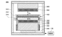
図9は、加熱装置300の模式的断面図であり、図8に示した段階の次の段階を示す。同図は、図6と同じ断面により示される。   FIG. 9 is a schematic cross-sectional view of the heating apparatus 300, and shows a stage subsequent to the stage shown in FIG. This figure is shown by the same cross section as FIG.

図示の段階において、下ステージ330は、アクチュエータ340に駆動されて上昇し始める。プッシュアップピン350も下ステージ330と共に上昇し、やがて、積層体102の下面において、基板101の外縁よりも径方向の外側で基板ホルダ202の枠部220に当接して、積層体102を持ち上げる。このように、プッシュアップピン350は、積層体102の支持部材を形成する。これにより、積層体102は、上ステージ360に向かって上昇する。   In the illustrated stage, the lower stage 330 is driven by the actuator 340 and starts to rise. The push-up pin 350 also rises together with the lower stage 330, and eventually, on the lower surface of the stacked body 102, comes into contact with the frame portion 220 of the substrate holder 202 on the outer side in the radial direction from the outer edge of the substrate 101, thereby lifting the stacked body 102. In this way, the push-up pin 350 forms a support member for the stacked body 102. As a result, the stacked body 102 rises toward the upper stage 360.

上記のような動作の過程で、下ステージ330のヒータプレート332と、積層体102の下面との距離Dは徐々に短くなる。このため、上ステージ360のヒータプレート362と積層体102上面との間の距離Dに対して、下ステージ330のヒータプレート332と積層体102下面との間の距離Dの方が短くなる。その結果、上側のヒータプレート362の輻射熱による積層体102上面の加熱よりも、下ステージ330のヒータプレート332の輻射熱による積層体102下面の加熱の方が大きくなる。 In the course of the above-mentioned operation, the heater plate 332 of the lower stage 330, the distance D 1 of the lower surface of the stack 102 is progressively shorter. Therefore, with respect to the distance D 2 between the heater plate 362 of the upper stage 360 and the laminate 102 top, towards the distance D 1 of the between the heater plate 332 and the stack 102 lower surface of the lower stage 330 is shortened . As a result, the heating of the lower surface of the laminate 102 by the radiant heat of the heater plate 332 of the lower stage 330 is greater than the heating of the upper surface of the laminate 102 by the radiant heat of the upper heater plate 362.

ただし、積層体102は、プッシュアップピン350により、下ステージ330から浮いている。このため、下側のヒータプレート332の輻射熱による積層体102下面の加熱が抑制され、上下のヒータプレート332、362による加熱温度の差は限定的になる。このように、プッシュアップピン350は、積層体102に対する加熱を抑制する加熱抑制部を形成する。   However, the stacked body 102 is floated from the lower stage 330 by the push-up pins 350. For this reason, heating of the lower surface of the laminated body 102 due to the radiant heat of the lower heater plate 332 is suppressed, and the difference in heating temperature between the upper and lower heater plates 332 and 362 becomes limited. In this way, the push-up pin 350 forms a heating suppression unit that suppresses heating of the stacked body 102.

図10は、加熱装置300の模式的断面図であり、図9に示した段階の次の段階を示す。同図は、図6と同じ断面により示される。   FIG. 10 is a schematic cross-sectional view of the heating apparatus 300, and shows a stage subsequent to the stage shown in FIG. This figure is shown by the same cross section as FIG.

図示の段階において、下ステージ330は更に上昇している。このため、下側のヒータプレート332と、積層体102の下面との距離Dよりも、上ステージ360のヒータプレート362下面と、積層体102の上面との距離Dの方が短くなる。このため、図示の段階においては、上ステージ360のヒータプレート362の輻射熱によって加熱される積層体102上面の温度が、下ステージ330のヒータプレート332の輻射熱によって加熱される積層体102下面の温度より高くなる。 In the illustrated stage, the lower stage 330 is further raised. For this reason, the distance D 2 between the lower surface of the heater plate 362 of the upper stage 360 and the upper surface of the multilayer body 102 is shorter than the distance D 1 between the lower heater plate 332 and the lower surface of the multilayer body 102. Therefore, in the illustrated stage, the temperature of the upper surface of the laminate 102 heated by the radiant heat of the heater plate 362 of the upper stage 360 is higher than the temperature of the lower surface of the laminate 102 heated by the radiant heat of the heater plate 332 of the lower stage 330. Get higher.

図11は、加熱装置300の模式的断面図であり、図10に示した段階の次の段階を示す。同図は、図6と同じ断面により示される。   FIG. 11 is a schematic cross-sectional view of the heating apparatus 300, showing the next stage after the stage shown in FIG. This figure is shown by the same cross section as FIG.

図示の段階において、下ステージ330は更に上昇している。このため、積層体102の上面が、上ステージ360のヒータプレート362下面に当接している。これにより、上ステージ360のヒータプレート362下面による積層体102の加熱は、輻射熱から伝導熱に替わる。   In the illustrated stage, the lower stage 330 is further raised. For this reason, the upper surface of the laminated body 102 is in contact with the lower surface of the heater plate 362 of the upper stage 360. Thereby, the heating of the laminated body 102 by the lower surface of the heater plate 362 of the upper stage 360 is changed from radiant heat to conduction heat.

また、プッシュアップピン350は、ばね352により上方に向かって付勢されているので、積層体102は、上側のヒータプレート362に対して押し付けられる。これにより、上側のヒータプレート362による積層体102上面の加熱が促進され、積層体102上面の昇温速度が上昇する。このように、プッシュアップピン350およびばね352は、積層体102上面に対する加熱促進部としても作用する。   Further, since the push-up pin 350 is biased upward by the spring 352, the stacked body 102 is pressed against the upper heater plate 362. Thereby, heating of the upper surface of the laminated body 102 by the upper heater plate 362 is promoted, and the temperature increase rate of the upper surface of the laminated body 102 is increased. As described above, the push-up pin 350 and the spring 352 also function as a heating promoting portion for the upper surface of the stacked body 102.

図12は、加熱装置300の模式的断面図であり、図11に示した段階の次の段階を示す。同図は、図6と同じ断面により示される。   FIG. 12 is a schematic cross-sectional view of the heating apparatus 300, and shows a stage subsequent to the stage shown in FIG. This figure is shown by the same cross section as FIG.

図示の段階においては、ばね352の付勢力に抗して下ステージ330が上昇し、下ステージ330のヒータプレート332上面が、積層体102の下面の接している。よって、下ステージ330のヒータプレート332上面による積層体102の加熱も、輻射熱から伝導熱に切り替わる。これにより、積層体102の上面においても、下面においても、ヒータプレート332、362の加熱による積層体102の昇温速度は略等しくなる。   In the illustrated stage, the lower stage 330 rises against the biasing force of the spring 352, and the upper surface of the heater plate 332 of the lower stage 330 is in contact with the lower surface of the stacked body 102. Therefore, the heating of the stacked body 102 by the upper surface of the heater plate 332 of the lower stage 330 is also switched from radiant heat to conduction heat. Thereby, the heating rate of the laminated body 102 due to the heating of the heater plates 332 and 362 becomes substantially equal on both the upper surface and the lower surface of the laminated body 102.

続いて、アクチュエータ340を更に動作させて、下ステージ330および上ステージ360の間で、既に加熱されている積層体102を強く加圧する。更に、積層体102を加熱および加圧した状態を、予め定められた時間が経過するまで維持することにより、積層体102において重ね合わされていた一対の基板101は相互に接合される。   Subsequently, the actuator 340 is further operated to strongly pressurize the stacked body 102 that has already been heated between the lower stage 330 and the upper stage 360. Further, by maintaining the state in which the stacked body 102 is heated and pressurized until a predetermined time elapses, the pair of substrates 101 stacked in the stacked body 102 are bonded to each other.

図13は、積層基板103の模式的断面図である。上記のように、積層体102を加熱加圧することにより、当初は重ね合わされただけであった一対の基板101は一体的な積層基板103となる。よって、加熱装置300から搬出した積層体102においては、一対の基板ホルダ201、202と積層基板103とを分離できる。基板接合装置100においては、積層体102から分離された積層基板103は、搬送ロボット140により基板カセット130に蓄積される。   FIG. 13 is a schematic cross-sectional view of the multilayer substrate 103. As described above, by heating and pressing the stacked body 102, the pair of substrates 101 that were only overlapped at the beginning become an integrated stacked substrate 103. Therefore, in the laminated body 102 carried out from the heating apparatus 300, the pair of substrate holders 201 and 202 and the laminated substrate 103 can be separated. In the substrate bonding apparatus 100, the laminated substrate 103 separated from the laminated body 102 is accumulated in the substrate cassette 130 by the transfer robot 140.

図14は、上記のような動作をする加熱装置300における積層体102の温度変化を示すグラフである。図中には、積層体102における上側の基板ホルダ201上面の温度が実線で、下側の基板ホルダ202下面の温度が点線で示される。   FIG. 14 is a graph showing a temperature change of the laminated body 102 in the heating apparatus 300 that operates as described above. In the drawing, the temperature of the upper surface of the upper substrate holder 201 in the stacked body 102 is indicated by a solid line, and the temperature of the lower surface of the lower substrate holder 202 is indicated by a dotted line.

図示のように、積層体102が加熱装置300に搬入された当初の期間Xは、図9を参照して説明した通り、積層体102下面とヒータプレート332の間隔Dの方が積層体102上面とヒータプレート362の間隔Dよりも短い。このため、一対の基板101の熱膨張係数が同等である場合は、期間Xにおいては、下側の基板ホルダ202の温度上昇が早く、積層体102の下側の基板101の熱変形量が、上側の基板101の熱変形量よりも大きくなる。 As shown, the initial term X 1 which the laminate 102 is carried into the heating device 300, as described with reference to FIG. 9, the direction of spacing D 1 of the stack 102 lower surface and the heater plate 332 laminate 102 shorter than the distance D 2 of the top surface and the heater plate 362. Therefore, if the thermal expansion coefficient of the pair of substrates 101 are equal, in a period X 1, fast temperature rise of the lower substrate holder 202, thermal deformation of the lower substrate 101 of the laminate 102 The amount of thermal deformation of the upper substrate 101 becomes larger.

続く期間Xには、下ステージ330が上昇するにつれて、図10を参照して説明した通り、積層体102上面がヒータプレート362に接近して、上側の基板ホルダ201の昇温速度が徐々に上昇する。このため、上側の基板ホルダ201の温度の上昇速度が徐々に高くなる。しかしながら、下側の基板ホルダ202の温度上昇が先行している。よって、期間Xにおいても、積層体102の上側の基板101の熱変形量よりも下側の基板101の熱変形量が依然として大きい。 The subsequent period X 2, as the lower stage 330 is increased, as described with reference to FIG. 10, the laminate 102 upper surface in close proximity to the heater plate 362, heating rate of the upper substrate holder 201 is gradually To rise. For this reason, the rate of temperature increase of the upper substrate holder 201 is gradually increased. However, the temperature rise of the lower substrate holder 202 is preceded. Therefore, even in the period X 2, is still large amount of thermal deformation of the lower substrate 101 than the thermal deformation of the upper substrate 101 of the stack 102.

しかしながら、図11に示したように、積層体102上面が上側のヒータプレート362に当接する直前の期間Xには、上側の基板ホルダ201と上側のヒータプレート362との間隔Dが、下側の基板ホルダ202と下側のヒータプレート332との間隔Dよりも狭くなるように変化するので、上側の基板101の昇温速度が急速に上昇して、上側の基板101の熱変形量が急速に増加する。やがて、期間X後のタイミングTには、下側の基板ホルダ202の温度と上側の基板ホルダ201の温度とが均衡すると共に、一対の基板101の熱変形量も等しくなる。 However, as shown in FIG. 11, a period X 3 immediately before the laminate 102 upper surface in contact with the upper side of the heater plate 362, the distance D 2 between the upper substrate holder 201 and the upper heater plate 362, the lower Since the temperature changes so as to be narrower than the distance D 1 between the upper substrate holder 202 and the lower heater plate 332, the temperature increase rate of the upper substrate 101 rapidly increases, and the amount of thermal deformation of the upper substrate 101 Increases rapidly. Eventually, the timing T 1 of the following period X 3, with temperature and is equilibrium temperature and an upper substrate holder 201 of the lower substrate holder 202, thermal deformation of the pair of substrates 101 become equal.

よって、当該タイミングTに、図12に示したように上下のヒータプレート332、362のいずれもが積層体102に当接すれば、以降の期間Xにおいては、積層体102の内部で厚さ方向の熱変形量の差が所定の値を超えることなく、積層体102全体を加熱し、更に加圧を開始できる。これにより、積層体102を形成する一対の基板101相互の温度差に起因する位置ずれを防止して、アライナ150において高精度に位置合わせされた状態で積層基板103を形成できる。なお、積層体102の加圧を開始する前に、積層体102に熱が行き渡る時間もとることにより、積層体102全体の温度を略均一にして、熱変形量の相違を充分に解消できる。 Therefore, if both of the upper and lower heater plates 332 and 362 abut on the laminated body 102 as shown in FIG. 12 at the timing T 1 , the thickness inside the laminated body 102 in the subsequent period X 4 . The entire laminate 102 can be heated and pressurization can be started without the difference in the amount of thermal deformation in the direction exceeding a predetermined value. Accordingly, it is possible to prevent the positional shift caused by the temperature difference between the pair of substrates 101 forming the stacked body 102 and to form the stacked substrate 103 in a state where the aligner 150 is aligned with high accuracy. Note that by taking the time for heat to spread to the laminated body 102 before the pressurization of the laminated body 102 is started, the temperature of the entire laminated body 102 can be made substantially uniform, and the difference in the amount of thermal deformation can be sufficiently eliminated.

なお、積層体102が予め定められた目標温度まで加熱された後、更に、目標温度を維持したまま、予め定めた加熱加圧時間が経過する期間Xにわたって積層体102を加圧することにより、一対の基板101が接合される。また、期間Xが経過した後、積層基板103を含む積層体102を、予め定められた予備冷却温度まで冷却した後に、積層体102を加熱装置300から搬出してもよい。 Incidentally, after the laminate 102 has been heated to the target temperature to a predetermined further while maintaining the target temperature, by pressurizing the laminate 102 over a period X 5 which between predetermined heating pressurization has elapsed, A pair of substrates 101 are joined. Further, after the period X 5 has elapsed, the laminate 102 comprising a multilayer substrate 103, after cooling to a predetermined pre-cooling temperature may be carried out a stack 102 from the heating device 300.

図15は、加熱装置300におけるヒータプレート332、362の温度変化を示すグラフである。なお、図中の「1周期」とは、ひとつの積層体102を搬入してから搬出するまでの期間を示す。よって、図15は、積層体102を加熱加圧する処理を繰り返す場合の温度変化を示す。   FIG. 15 is a graph showing temperature changes of the heater plates 332 and 362 in the heating apparatus 300. In addition, “one cycle” in the figure indicates a period from when one laminated body 102 is carried in to when it is carried out. Therefore, FIG. 15 shows a temperature change when the process of heating and pressurizing the laminate 102 is repeated.

上記のように、加熱装置300においては、積層体102の上面と下面との温度の相違を、加熱抑制部および加熱促進部により補正する。このため、図示のように、加熱装置300において、ヒータプレート332、362の温度は、加熱加圧処理が終わった積層体102を冷却する期間と、積層体102が搬出された直後にヒータプレート332、362の表面が露出して放射熱が増加する期間とを除いて、ヒータプレート332、362の温度を、加熱目標温度の付近に維持し続けることができる。よって、ヒータプレート332、362の加熱および冷却に要する時間を省き、積層基板103を継続的に製造する場合のスループットを向上させることができる。   As described above, in the heating device 300, the temperature difference between the upper surface and the lower surface of the stacked body 102 is corrected by the heating suppression unit and the heating promotion unit. For this reason, as shown in the figure, in the heating apparatus 300, the temperature of the heater plates 332 and 362 is the same as the period for cooling the laminated body 102 after the heating and pressurizing process and the heater plate 332 immediately after the laminated body 102 is carried out. The temperature of the heater plates 332 and 362 can be kept near the heating target temperature except for the period when the surface of 362 is exposed and the radiant heat increases. Therefore, the time required for heating and cooling the heater plates 332 and 362 can be omitted, and the throughput when the laminated substrate 103 is continuously manufactured can be improved.

なお、上記の例では、プッシュアップピン350を利用して加熱促進部および加熱抑制部を形成した。しかしながら、単一の加熱促進部および加熱抑制部では、積層体102の上面および下面の温度差を補正し切れない場合がる。このような場合は、更に、他の加熱抑制部または加熱促進部を併用して、温度差を高精度に補正してもよい。   In the above example, the heating promotion part and the heating suppression part are formed using the push-up pin 350. However, in a single heating promotion part and a heating suppression part, the temperature difference of the upper surface and lower surface of the laminated body 102 may not be correct | amended completely. In such a case, the temperature difference may be corrected with high accuracy by using another heating suppression unit or heating promotion unit in combination.

こうして、アライナ150において位置合わせして重ね合わせた基板を、位置合わせ精度を廉価させることなく接合できる加熱装置300が提供される。このような加熱装置300を備えた基板接合装置100は、積層構造の半導体装置を製造する半導体装置製造として使用できる。   In this way, the heating apparatus 300 is provided that can join the substrates that are aligned and overlapped in the aligner 150 without lowering the alignment accuracy. The substrate bonding apparatus 100 provided with such a heating apparatus 300 can be used as a semiconductor device manufacturing method for manufacturing a semiconductor device having a laminated structure.

図16は、他の加熱装置301の模式的断面図である。図示の加熱装置301は、次に説明する点を除くと、加熱装置300と同じ構造を有し、搬入された積層体を加熱すると共に加圧することもできる。よって、共通の要素には同じ参照番号を付して重複する説明を省く。また、図16は、図6の加熱装置300と同じ断面によって示される。   FIG. 16 is a schematic cross-sectional view of another heating device 301. Except for the points described below, the illustrated heating device 301 has the same structure as the heating device 300 and can heat and pressurize the loaded laminate. Therefore, common elements are denoted by the same reference numerals, and redundant description is omitted. Moreover, FIG. 16 is shown by the same cross section as the heating apparatus 300 of FIG.

図示の加熱装置301は、仮置台314を備えていない点で、加熱装置300と相違する。加熱装置301において、搬送ロボット140により搬入された積層体102は、仮置台314ではなく、プッシュアップピン350に受け渡される。これにより、仮置台314からプッシュアップピン350への受け渡しに要する時間を短縮し、積層体102の表裏に対して加熱が不均衡になる時間を短縮する加熱抑制部が形成される。   The illustrated heating device 301 is different from the heating device 300 in that the temporary mounting table 314 is not provided. In the heating device 301, the stacked body 102 carried in by the transport robot 140 is delivered to the push-up pin 350 instead of the temporary table 314. Thereby, the time required for delivery from the temporary table 314 to the push-up pin 350 is shortened, and a heating suppression unit is formed that shortens the time when heating is unbalanced with respect to the front and back of the laminate 102.

図17は、また他の加熱装置302の模式的断面図である。図示の加熱装置302は、次に説明する点を除くと、加熱装置300と同じ構造を有し、搬入された積層体を加熱すると共に加圧することもできる。よって、共通の要素には同じ参照番号を付して重複する説明を省く。また、図17は、図6の加熱装置300と同じ断面によって示される。   FIG. 17 is a schematic cross-sectional view of still another heating device 302. Except for the points described below, the illustrated heating device 302 has the same structure as the heating device 300, and can heat and pressurize the loaded laminated body. Therefore, common elements are denoted by the same reference numerals, and redundant description is omitted. Moreover, FIG. 17 is shown by the same cross section as the heating apparatus 300 of FIG.

加熱装置302は、上ステージ360にプッシュダウンピン351が設けられている点で、加熱装置300と異なる構造を有する。また、加熱装置302は、加熱装置301と同様に、仮置台314が省かれている。   The heating device 302 has a structure different from that of the heating device 300 in that a push-down pin 351 is provided on the upper stage 360. Further, the heating device 302 is similar to the heating device 301 in that the temporary table 314 is omitted.

加熱装置302において、上ステージ360は、その側面に沿って、上ステージ360に対して昇降可能な複数のプッシュダウンピン351を有する。プッシュダウンピン351は、上ステージ360およびヒータプレート362の周囲に沿って3本以上配される。   In the heating device 302, the upper stage 360 has a plurality of push-down pins 351 that can move up and down with respect to the upper stage 360 along the side surfaces thereof. Three or more push-down pins 351 are arranged along the periphery of the upper stage 360 and the heater plate 362.

また、プッシュダウンピン351の各々は、ばね353により、図中下方に向かって付勢されている。ばね353は、下ステージ330に設けられたプッシュアップピン350のばね352と略同じばね定数を有する。このような加熱装置302においては、搬入された積層体102は、加熱装置301と同様に、直接にプッシュアップピン350により支持される。   Each push-down pin 351 is urged downward by a spring 353 in the drawing. The spring 353 has substantially the same spring constant as the spring 352 of the push-up pin 350 provided on the lower stage 330. In such a heating device 302, the loaded stacked body 102 is directly supported by push-up pins 350 as in the heating device 301.

図18は、加熱装置302の模式的断面図であり、加熱装置302の動作を示す。図示の段階において、下ステージ330は、アクチュエータ340に駆動されて上昇し始める。プッシュアップピン350も下ステージ330と共に上昇する。これにより、積層体102の上面は、プッシュダウンピン351の下端に当接する。   FIG. 18 is a schematic cross-sectional view of the heating device 302 and shows the operation of the heating device 302. In the illustrated stage, the lower stage 330 is driven by the actuator 340 and starts to rise. The push-up pin 350 also rises with the lower stage 330. Thereby, the upper surface of the laminated body 102 contacts the lower end of the push-down pin 351.

既に説明した通り、下ステージ330に設けられたプッシュアップピン350は、積層体102の下面に対する加熱抑制部を形成する。同様に、加熱装置302においては、上ステージ360に設けられたプッシュダウンピン351も、積層体102の上面に対する加熱抑制部を形成する。   As already described, the push-up pin 350 provided on the lower stage 330 forms a heating suppression unit for the lower surface of the stacked body 102. Similarly, in the heating device 302, the push-down pin 351 provided on the upper stage 360 also forms a heating suppression unit for the upper surface of the stacked body 102.

ここで、プッシュアップピン350のばね352と、プッシュダウンピン351のばね353とは、等しいバネ定数を有するので、下ステージ330が更に上昇した場合に、プッシュアップピン350の縮み量と、プッシュダウンピン351の縮み量は等しい。よって、積層体102の下面とヒータプレート332の間隔Dと、積層体102の上面とヒータプレート362の間隔Dとは、常に等しく保たれる。よって、積層体102の加熱は、上面と下面で均衡する。このような加熱の均衡は、図19に示すように、積層体102が上下のヒータプレート332、362に当接するまで継続される。 Here, since the spring 352 of the push-up pin 350 and the spring 353 of the push-down pin 351 have the same spring constant, the amount of contraction of the push-up pin 350 and the push-down when the lower stage 330 is further raised. The amount of contraction of the pin 351 is equal. Therefore, the distance D 4 of the lower surface and the heater plate 332 of the stack 102, the distance D 3 of the upper surface and the heater plate 362 of the stack 102 is always equal maintained. Therefore, the heating of the laminated body 102 is balanced between the upper surface and the lower surface. This balance of heating is continued until the laminate 102 abuts on the upper and lower heater plates 332 and 362 as shown in FIG.

図20は、上記のような動作をする加熱装置300における積層体102の温度変化を示すグラフである。図中には、積層体102における上側の基板ホルダ201上面の温度が実線で、下側の基板ホルダ202下面の温度が点線で示される。   FIG. 20 is a graph showing a temperature change of the laminated body 102 in the heating apparatus 300 that operates as described above. In the drawing, the temperature of the upper surface of the upper substrate holder 201 in the stacked body 102 is indicated by a solid line, and the temperature of the lower surface of the lower substrate holder 202 is indicated by a dotted line.

図示のように、加熱装置302においては、積層体102がプッシュアップピン350およびプッシュダウンピン351に挟まれた後の期間Y3、およびYに、積層体102の上面および下面に対する加熱が等しくなる。よって、これらの期間Y3、およびYにおける基板101の熱変形量の差が所定の値を超えることはない。 As shown in the figure, in the heating device 302, heating of the upper surface and the lower surface of the stacked body 102 is performed in the periods Y 3, Y 4 and Y 5 after the stacked body 102 is sandwiched between the push-up pins 350 and the push-down pins 351. Are equal. Therefore, the difference in the amount of thermal deformation of the substrate 101 in these periods Y 3, Y 4 and Y 5 does not exceed a predetermined value.

しかしながら、積層体102が加熱装置302に搬入された直後の期間Yおよび期間Yに生じた、積層体102の上面および下面の温度の相違に起因する基板101相互の熱変形量の相違は、最終的に積層体102の温度が定常状態になるまで持ち越される。ただし、熱変形量に相違が生じる期間Y、Yが短いので、基板ホルダ201、202の温度上昇が定常状態になった直後の短い期間Yに熱変形量の相違は解消される。なお、積層体102の加圧を開始する前に、積層体102に熱が行き渡る時間もとることにより、積層体102全体の温度を略均一にして、熱変形量の相違を充分に解消できる。 However, the laminate 102 occurs in time period Y 1 and period Y 2 immediately after being conveyed to the heating device 302, the difference in substrate 101 mutual thermal deformation amount due to difference of upper and lower surfaces of the temperature of the stack 102 Finally, it is carried over until the temperature of the laminated body 102 reaches a steady state. However, since the periods Y 1 and Y 2 in which the difference in thermal deformation amount is short are short, the difference in the thermal deformation amount is eliminated in the short period Y 6 immediately after the temperature rise of the substrate holders 201 and 202 becomes a steady state. Note that by taking the time for heat to spread to the laminated body 102 before the pressurization of the laminated body 102 is started, the temperature of the entire laminated body 102 can be made substantially uniform, and the difference in the amount of thermal deformation can be sufficiently eliminated.

図21は、加熱装置302の他の運用を説明する図である。加熱装置302においては、更に、加熱促進部を設けることにより、上記の搬入直後における温度の差を補正する。   FIG. 21 is a diagram for explaining another operation of the heating device 302. In the heating device 302, the difference in temperature immediately after the carry-in is corrected by further providing a heating promoting portion.

加熱装置302に積層体102が搬入された当初の期間Z、ZおよびZにおける加熱装置302の挙動は、図20に示した期間期間Y、YおよびYにおける加熱装置302の挙動と変わらない。しかしながら、図示のスケジュールでは、積層体102の両面がヒータプレート332、362に当接した後であって、加圧を開始する前に、上側の基板ホルダ201の静電チャックを利用して、積層体102を上側のヒータプレート362に吸着させる。これにより、加圧開始直前の期間Zにおいては、上側の基板ホルダ201の温度が急速に上昇する。 The behavior of the heating device 302 in the initial periods Z 1 , Z 2, and Z 3 when the laminate 102 is carried into the heating device 302 is the same as that of the heating device 302 in the period periods Y 1 , Y 2, and Y 3 shown in FIG. It does not change with behavior. However, in the illustrated schedule, after both surfaces of the laminated body 102 are in contact with the heater plates 332 and 362 and before the pressurization is started, the electrostatic chuck of the upper substrate holder 201 is used to perform lamination. The body 102 is attracted to the upper heater plate 362. Thus, in the period Z 5 immediately before starting pressurization, the temperature of the upper substrate holder 201 is rapidly increased.

即ち、既に説明した通り、積層体102を形成する基板ホルダ201、202には、静電チャックが設けられている。そこで、図に示すように、積層体102が上下のヒータプレート332、362に接した直後に、上側の基板ホルダ201の静電チャックを動作させる。静電チャックは上方のヒータプレート362も吸着するので、積層体102の上面のヒータプレート362に対する接触圧が高くなる。これにより、積層体102上面の加熱を促進して、搬入直後の温度の不均衡を補正できる。これにより、基板101相互の熱変形量の相違は、早期に解消される。このように、制御部170は、積層体102を吸着する静電チャック等を制御して基板101を含む積層体102の温度を制御することもできる。   That is, as already described, the substrate holders 201 and 202 that form the stacked body 102 are provided with electrostatic chucks. Therefore, as shown in the figure, the electrostatic chuck of the upper substrate holder 201 is operated immediately after the stacked body 102 contacts the upper and lower heater plates 332 and 362. Since the electrostatic chuck also attracts the upper heater plate 362, the contact pressure of the upper surface of the laminate 102 to the heater plate 362 is increased. Thereby, the heating of the upper surface of the laminated body 102 can be promoted, and the temperature imbalance immediately after carrying in can be corrected. Thereby, the difference in the amount of thermal deformation between the substrates 101 is eliminated at an early stage. As described above, the control unit 170 can also control the temperature of the stacked body 102 including the substrate 101 by controlling an electrostatic chuck or the like that attracts the stacked body 102.

なお、図21の例では、積層体102が上下のヒータプレート332、362に接した直後に、上側の基板ホルダ201の静電チャックを動作させる例を示したが、上側の基板ホルダ201の静電チャックを動作させるタイミングは、上側の基板ホルダ201がヒータプレート362に接触してから加圧が開始するまでの間であればいつでもよい。   In the example of FIG. 21, the example in which the electrostatic chuck of the upper substrate holder 201 is operated immediately after the stacked body 102 contacts the upper and lower heater plates 332 and 362 is shown. The timing for operating the electric chuck may be any time from when the upper substrate holder 201 comes into contact with the heater plate 362 to when pressurization is started.

図22は、また他の加熱装置303の模式的な断面図である。図示の加熱装置303は、次に説明する点を除くと、加熱装置300と同じ構造を有し、搬入された積層体を加熱すると共に加圧することもできる。よって、共通の要素には同じ参照番号を付して重複する説明を省く。また、図22は、図6の加熱装置300と同じ断面によって示される。   FIG. 22 is a schematic cross-sectional view of still another heating device 303. Except for the points described below, the illustrated heating device 303 has the same structure as the heating device 300, and can heat and pressurize the loaded laminated body. Therefore, common elements are denoted by the same reference numerals, and redundant description is omitted. 22 is shown by the same cross section as the heating device 300 of FIG.

図示の加熱装置303は、昇降する仮置台315を備え、ヒータプレート332、362に挟まれる直前まで、積層体102が仮置台315に支持される点で加熱装置300と異なる構造を有する。また、下ステージ330からプッシュアップピン350が省かれる代わりに、仮置台315と下ステージ330とを連動させる仕組みを備える点で、加熱装置300と異なる構造を有する。   The illustrated heating device 303 includes a temporary table 315 that moves up and down, and has a structure different from that of the heating device 300 in that the stacked body 102 is supported by the temporary table 315 until just before being sandwiched between the heater plates 332 and 362. Further, instead of omitting the push-up pin 350 from the lower stage 330, it has a structure different from that of the heating device 300 in that a mechanism for interlocking the temporary placement table 315 and the lower stage 330 is provided.

加熱装置303において、仮置台315は、断熱容器310の内部を垂直に昇降する。また、仮置台315は、ばね376により、図中上方に向かって付勢されている。更に、仮置台315の下面には滑車372が設けられる。   In the heating device 303, the temporary table 315 moves up and down vertically inside the heat insulating container 310. The temporary table 315 is urged upward by a spring 376 in the drawing. Further, a pulley 372 is provided on the lower surface of the temporary table 315.

滑車372に掛けられたワイヤ374の一端は、断熱容器310の底面に結合される。また、当該ワイヤ374の他端は、下ステージ330に対して結合される。これにより、下ステージ330が昇降した場合、仮置台315は、下ステージ330の昇降量の半分の移動量で昇降する。   One end of the wire 374 hung on the pulley 372 is coupled to the bottom surface of the heat insulating container 310. Further, the other end of the wire 374 is coupled to the lower stage 330. As a result, when the lower stage 330 moves up and down, the temporary table 315 moves up and down with a movement amount that is half the amount of movement of the lower stage 330.

よって、搬入した積層体102を仮置台315に支持させた状態で、下ステージ330を上昇させている間、上側のヒータプレート362と積層体102上面との間隔Dは、下側のヒータプレート332と積層体102下面との間隔Dと、常に等しくなる。これにより、積層体102上面の温度と積層体102下面の温度は略等しくなるため、積層された基板101の熱変形量の差が所定の値を超えることが防止される。 Thus, a laminate 102 carried in a state of being supported on the temporary placement table 315, while raising the lower stage 330, the distance D 5 between the upper heater plate 362 and the stack 102 top, the lower heater plate 332 and the distance D 6 between the stack 102 lower surface, always equal. As a result, the temperature of the upper surface of the laminated body 102 and the temperature of the lower surface of the laminated body 102 become substantially equal, so that the difference in the amount of thermal deformation of the laminated substrate 101 is prevented from exceeding a predetermined value.

図23は、また他の加熱装置304の模式的断面図である。図示の加熱装置304は、次に説明する点を除くと、加熱装置300と同じ構造を有し、搬入された積層体を加熱すると共に加圧することもできる。よって、共通の要素には同じ参照番号を付して重複する説明を省く。また、図23は、図6の加熱装置300と同じ断面によって示される。   FIG. 23 is a schematic cross-sectional view of still another heating device 304. Except for the points described below, the illustrated heating device 304 has the same structure as the heating device 300, and can heat and pressurize the loaded laminate. Therefore, common elements are denoted by the same reference numerals, and redundant description is omitted. Moreover, FIG. 23 is shown by the same cross section as the heating apparatus 300 of FIG.

加熱装置304は、下ステージ330に複数のプッシュアップピン350を備える。プッシュアップピン350は、アクチュエータ342により駆動されて、下ステージ330に対する突出量を変化させることができる。また、加熱装置304において加熱加圧される積層体102においては、基板ホルダ201、202の各々が、温度センサ381、382を有し、個々の基板ホルダ201、202の温度を個別に検出できる。   The heating device 304 includes a plurality of push-up pins 350 on the lower stage 330. The push-up pin 350 can be driven by an actuator 342 to change the protrusion amount with respect to the lower stage 330. Moreover, in the laminated body 102 heated and pressurized by the heating device 304, each of the substrate holders 201 and 202 includes temperature sensors 381 and 382, and the temperatures of the individual substrate holders 201 and 202 can be individually detected.

更に、加熱装置304は、温度センサ381、382が検出した温度に基づいて、加熱を制御する加熱制御部380を備える。加熱制御部380は、温度センサ381,382の検出温度に基づいて、アクチュエータ342および下ステージ330の駆動を制御して、プッシュアップピン350の上昇量および上昇速度の少なくとも一方と、下ステージ330の上昇量および上昇速度の少なくとも一方とをそれぞれ変化させる。これにより、基板ホルダ201,202の温度すなわち温度センサ381,382の検出温度に応じて、ヒータプレート332、362と積層体102との間隔を調整することができる。これにより、加熱装置304は、積層体102を形成する一対の基板101の熱変形量の差が所定の値を超えないように積層体102を加熱できる。   Furthermore, the heating device 304 includes a heating control unit 380 that controls heating based on the temperatures detected by the temperature sensors 381 and 382. The heating control unit 380 controls the driving of the actuator 342 and the lower stage 330 based on the temperature detected by the temperature sensors 381 and 382, and at least one of the rising amount and the rising speed of the push-up pin 350 and the lower stage 330. At least one of the rising amount and the rising speed is changed. Thereby, the space | interval of the heater plates 332 and 362 and the laminated body 102 can be adjusted according to the temperature of the substrate holders 201 and 202, that is, the detected temperature of the temperature sensors 381 and 382. Accordingly, the heating device 304 can heat the stacked body 102 so that the difference in the amount of thermal deformation between the pair of substrates 101 forming the stacked body 102 does not exceed a predetermined value.

これにより、上側のヒータプレート362と積層体102上面との間隔Dが、下側のヒータプレート332と積層体102下面との間隔Dと、常に等しく保つことができる。よって、積層体102上面の温度と積層体102下面の温度を略等しくして、積層された基板101の熱変形量の差が所定の値を超えることを防止できる。 Thus, the distance D 7 between the upper heater plate 362 and the upper surface of the stacked body 102 can always be kept equal to the distance D 8 between the lower heater plate 332 and the lower surface of the stacked body 102. Therefore, the temperature of the upper surface of the stacked body 102 and the temperature of the lower surface of the stacked body 102 can be made substantially equal to prevent the difference in thermal deformation amount of the stacked substrates 101 from exceeding a predetermined value.

なお、加熱制御部380は、温度センサ381、382により基板101の温度または熱膨張量を監視する代わりに、積層体102を形成する基板101および基板ホルダ201、202について既知の情報を利用して、間隔D、Dの適切な値を予測して、プッシュアップピン350の突出量を制御してもよい。また、一対の基板101の熱変形量の差が所定の値を超えない間隔D、Dの大きさが予め分かっている場合は、温度センサ381,382を用いることなく、プッシュアップピン350の上昇量および上昇速度の少なくとも一方と、下ステージ330の上昇量および上昇速度の少なくとも一方とを制御することにより、一対の基板101の温度をそれぞれ制御してもよい。 Note that the heating control unit 380 uses known information about the substrate 101 and the substrate holders 201 and 202 forming the stacked body 102 instead of monitoring the temperature or thermal expansion amount of the substrate 101 by the temperature sensors 381 and 382. The protrusion amount of the push-up pin 350 may be controlled by predicting appropriate values of the distances D 7 and D 8 . In addition, when the magnitudes of the distances D 7 and D 8 at which the difference in thermal deformation amount between the pair of substrates 101 does not exceed a predetermined value are known in advance, the push-up pins 350 are used without using the temperature sensors 381 and 382. The temperature of the pair of substrates 101 may be controlled by controlling at least one of the ascending amount and the ascending speed and at least one of the ascending amount and the ascending speed of the lower stage 330, respectively.

上記の加熱装置300、301、302、303、304においては、いずれも、受動的に動作する加熱抑制部を例にあげた。しかしながら、プッシュアップピン350、プッシュダウンピン351および仮置台315を移動させるアクチュエータを設けて、能動的な制御をしてもよい。   In each of the heating devices 300, 301, 302, 303, and 304, a heating suppression unit that operates passively is taken as an example. However, active control may be performed by providing an actuator that moves the push-up pin 350, the push-down pin 351, and the temporary table 315.

上記の例では、下ステージ330および上ステージ360に加熱抑制部または加熱促進部を設ける例を主に説明した。しかしながら、例えば、加熱装置300、301、302、303と同じ温度環境に搬送ロボット140が存在する場合は、積層体102を搬入および搬出する搬送ロボット140を、積層体102とヒータプレート332、362との間隔を変化させる加熱抑制部または加熱促進部として用いてもよい。   In the above example, the example in which the lower stage 330 and the upper stage 360 are provided with the heating suppression unit or the heating promotion unit has been mainly described. However, for example, when the transfer robot 140 exists in the same temperature environment as the heating devices 300, 301, 302, and 303, the transfer robot 140 that loads and unloads the stacked body 102 is replaced with the stacked body 102 and the heater plates 332 and 362. You may use as a heating suppression part or a heating promotion part which changes the space | interval.

図24は、また他の加熱装置305の模式的断面図である。図示の加熱装置305は、次に説明する点を除くと、加熱装置300と同じ構造を有し、搬入された積層体を加熱すると共に加圧することもできる。よって、共通の要素には同じ参照番号を付して重複する説明を省く。また、図24は、図6の加熱装置300と同じ断面によって示される。   FIG. 24 is a schematic cross-sectional view of still another heating device 305. Except for the points described below, the illustrated heating device 305 has the same structure as the heating device 300, and can heat and pressurize the loaded laminate. Therefore, common elements are denoted by the same reference numerals, and redundant description is omitted. Moreover, FIG. 24 is shown by the same cross section as the heating apparatus 300 of FIG.

加熱装置305は、プッシュアップピン350を備えていない代わりに、ヒータプレート332、362の温度を、個別且つ急速に変化させることができる。また、加熱装置305において加熱加圧される積層体102においては、基板ホルダ201、202の各々が、温度センサ381、382を有し、個々の基板ホルダ201、202の温度を個別に検出できる。   The heating device 305 can change the temperature of the heater plates 332 and 362 individually and rapidly instead of including the push-up pin 350. Moreover, in the laminated body 102 heated and pressurized by the heating device 305, each of the substrate holders 201 and 202 has temperature sensors 381 and 382, and the temperatures of the individual substrate holders 201 and 202 can be individually detected.

更に、加熱装置305は、温度センサ381、382が検出した温度に基づいて、ヒータプレート332、362による加熱温度を個別に制御する加熱制御部380を備える。これにより、加熱装置305は、積層体102を形成する一対の基板101に熱変形量の差が所定の値を超えないように積層体102を加熱することができる。   Furthermore, the heating device 305 includes a heating control unit 380 that individually controls the heating temperatures of the heater plates 332 and 362 based on the temperatures detected by the temperature sensors 381 and 382. Accordingly, the heating device 305 can heat the stacked body 102 so that the difference in thermal deformation amount between the pair of substrates 101 forming the stacked body 102 does not exceed a predetermined value.

よって、積層体102とヒータプレート332、362との間隔、接触圧力等を配慮することなく、積層体102を加熱、加圧できる。また、搬送ロボット140、プッシュアップピン350および仮置台314、315相互における積層体102の受け渡しに要する手間と時間を節約できるので、基板接合装置100の制御を簡潔にすることができると共に、スループットを向上できる。   Therefore, the laminate 102 can be heated and pressurized without considering the distance between the laminate 102 and the heater plates 332 and 362, contact pressure, and the like. In addition, since it is possible to save the labor and time required to transfer the laminate 102 between the transfer robot 140, the push-up pins 350, and the temporary placement tables 314 and 315, the control of the substrate bonding apparatus 100 can be simplified and the throughput can be reduced. It can be improved.

また、ヒータプレート332、362等の加熱源から伝わる熱により、積層体102に生じた面方向および厚さ方向の熱変形の差が前記した所定の閾値を超える前に、位置合わせされた一対の基板101の位置関係を維持するロック圧力で積層体を加圧して、加熱過程に基板101間に生じる熱変形量の差によるずれを回避してもよい。この場合、基板101の熱による撓み変形を抑制するロック圧力で基板を加圧することにより、基板101の撓み変形による厚さ方向のずれを防止することができる。   In addition, the heat transferred from a heating source such as the heater plates 332 and 362 causes a pair of aligned positions before the difference in thermal deformation between the surface direction and the thickness direction generated in the laminate 102 exceeds the predetermined threshold value. The laminate may be pressed with a lock pressure that maintains the positional relationship of the substrate 101 to avoid a shift due to a difference in the amount of thermal deformation that occurs between the substrates 101 during the heating process. In this case, it is possible to prevent the displacement in the thickness direction due to the bending deformation of the substrate 101 by pressing the substrate with a lock pressure that suppresses the bending deformation due to the heat of the substrate 101.

また、一対の基板101にロック圧力をかけることにより、一対の基板101間で熱の伝達が行われるため、一対の基板101の温度を均等にすることができる。これにより、一対の基板101の熱膨張係数が同等である場合は、一対の基板101間での熱膨張による変形量の差の発生を抑制することができる。   In addition, since heat is transmitted between the pair of substrates 101 by applying a locking pressure to the pair of substrates 101, the temperature of the pair of substrates 101 can be made uniform. Thereby, when the thermal expansion coefficient of a pair of board | substrate 101 is equivalent, generation | occurrence | production of the difference of the deformation amount by thermal expansion between a pair of board | substrates 101 can be suppressed.

また更に、基板ホルダ201、202における保持面212と反対側の面に、ヒータプレート332、362からの熱伝導を妨げる熱障壁層、反射層等を設けて、低レベルの輻射熱の影響を排除するようにしてもよい。また更に、上記の例では専ら加熱する場合について説明したが、積層体の一部を冷却することにより、加熱の不均衡を補正してもよい。   Furthermore, a thermal barrier layer, a reflective layer, and the like that prevent heat conduction from the heater plates 332 and 362 are provided on the surface of the substrate holders 201 and 202 opposite to the holding surface 212 to eliminate the influence of low-level radiant heat. You may do it. Furthermore, in the above example, the case of heating exclusively has been described, but the heating imbalance may be corrected by cooling a part of the laminate.

また、上記した実施例では、基板ホルダ201,202を用いて1対の基板101を互いに接合する例を示した。しかしながら、基板ホルダ201,202を用いずに1対の基板101を互いに接合する場合に本発明を適用してもよい。また、上記した実施例では、一対の基板101が同等の熱膨張係数を有した材料からなる例を示したが、互いに異なる熱膨張係数を有する材料から成る一対の基板を用いてもよい。この場合、上下のヒータプレート332、362と一対の基板101との間隔やヒータプレート332、362の温度は、それぞれ一対の基板101の温度が等しくなるように制御される必要はなく、一対の基板の熱変形量の差が所定の値を超えないように、材料に応じた値に設定される。また、一対の基板の材料に対応した間隔の大きさや温度に応じて、プッシュアップピン350や下ステージ330等の駆動が制御される。   In the above-described embodiment, an example in which the pair of substrates 101 are bonded to each other using the substrate holders 201 and 202 has been described. However, the present invention may be applied when a pair of substrates 101 are bonded to each other without using the substrate holders 201 and 202. In the above-described embodiment, an example in which the pair of substrates 101 is made of a material having the same thermal expansion coefficient is shown, but a pair of substrates made of materials having different thermal expansion coefficients may be used. In this case, the distance between the upper and lower heater plates 332 and 362 and the pair of substrates 101 and the temperature of the heater plates 332 and 362 do not need to be controlled so that the temperatures of the pair of substrates 101 are equal to each other. A value corresponding to the material is set so that the difference in the amount of thermal deformation of the material does not exceed a predetermined value. Further, the drive of the push-up pin 350, the lower stage 330, and the like is controlled in accordance with the size and temperature of the interval corresponding to the material of the pair of substrates.

以上、実施の形態を用いて本発明を説明したが、本発明の技術的範囲は上記実施の形態に記載の範囲には限定されない。上記実施の形態に、多様な変更または改良を加えることが可能であることが当業者に明らかである。その様な変更または改良を加えた形態も本発明の技術的範囲に含まれ得ることが、特許請求の範囲の記載から明らかである。   As mentioned above, although this invention was demonstrated using embodiment, the technical scope of this invention is not limited to the range as described in the said embodiment. It will be apparent to those skilled in the art that various modifications or improvements can be added to the above-described embodiment. It is apparent from the scope of the claims that the embodiments added with such changes or improvements can be included in the technical scope of the present invention.

特許請求の範囲、明細書、および図面中において示した装置、システム、プログラム、および方法における動作、手順、ステップ、および段階等の各処理の実行順序は、特段「より前に」、「先立って」等と明示しておらず、また、前の処理の出力を後の処理で用いるのでない限り、任意の順序で実現しうることに留意すべきである。特許請求の範囲、明細書、および図面中の動作フローに関して、便宜上「まず、」、「次に、」等を用いて説明したとしても、この順で実施することが必須であることを意味するものではない。   The order of execution of each process such as operations, procedures, steps, and stages in the apparatus, system, program, and method shown in the claims, the description, and the drawings is particularly “before” or “prior to”. It should be noted that the output can be realized in any order unless the output of the previous process is used in the subsequent process. Regarding the operation flow in the claims, the description, and the drawings, even if it is described using “first”, “next”, etc. for convenience, it means that it is essential to carry out in this order. It is not a thing.

100 基板接合装置、101 基板、102 積層体、103 積層基板、110 筐体、120、130 基板カセット、140 搬送ロボット、150 アライナ、170 制御部、200、201、202 基板ホルダ、210 保持部、212 保持面、214 埋設電極、216 結合部、220 枠部、222 フランジ部、228 外部電極、230 連結部、234 吸着部、236 被吸着部、300、301、302、303、304、305 加熱装置、310 断熱容器、312 搬入口、314、315 仮置台、320 シャッタ、330 下ステージ、332、362 ヒータプレート、340、342 アクチュエータ、350 プッシュアップピン、351 プッシュダウンピン、352、353、376 ばね、360 上ステージ、372 滑車、374 ワイヤ、380 加熱制御部、381、382 温度センサ 100 substrate bonding apparatus, 101 substrate, 102 laminated body, 103 laminated substrate, 110 housing, 120, 130 substrate cassette, 140 transport robot, 150 aligner, 170 control unit, 200, 201, 202 substrate holder, 210 holding unit, 212 Holding surface, 214 Embedded electrode, 216 Coupling part, 220 Frame part, 222 Flange part, 228 External electrode, 230 Connecting part, 234 Adsorption part, 236 Adsorbed part, 300, 301, 302, 303, 304, 305 Heating device, 310 Insulating container, 312 Loading port, 314, 315 Temporary table, 320 Shutter, 330 Lower stage, 332, 362 Heater plate, 340, 342 Actuator, 350 Push-up pin, 351 Push-down pin, 352, 353, 376 Spring, 360 Up Stage, 372 pulley, 374 wire, 380 Heating control unit, 381, 382 Temperature sensor

Claims (18)

位置合わせされた第1の基板および第2の基板の少なくとも一方を加熱する加熱部と、
前記第1の基板および前記第2の基板の少なくとも一方の熱変形による前記第1の基板および前記第2の基板間の位置ずれが閾値を超えないように、前記第1の基板および前記第2の基板の少なくとも一方の温度を制御する制御部と、
を備え
前記加熱部は、前記第1の基板を加熱する第1の加熱部と、前記第2の基板を加熱する第2の加熱部とを備え、前記制御部は、前記第1の加熱部と前記第1の基板との第1の間隔、および、前記第2の加熱部と前記第2の基板との第2の間隔を変化させる加熱装置。
A heating unit that heats at least one of the aligned first substrate and second substrate;
The first substrate and the second substrate are arranged such that a displacement between the first substrate and the second substrate due to thermal deformation of at least one of the first substrate and the second substrate does not exceed a threshold value. A controller for controlling the temperature of at least one of the substrates;
Equipped with a,
The heating unit includes a first heating unit that heats the first substrate, and a second heating unit that heats the second substrate, and the control unit includes the first heating unit and the second heating unit. A heating apparatus that changes a first interval between the first substrate and a second interval between the second heating unit and the second substrate .
前記制御部は、前記第1の基板および前記第2の基板の少なくとも一方に対する加熱を抑制することにより前記温度を制御する請求項1に記載の加熱装置。   The heating apparatus according to claim 1, wherein the control unit controls the temperature by suppressing heating of at least one of the first substrate and the second substrate. 前記制御部は、前記第1の基板および前記第2の基板の少なくとも一方に対する加熱を促進することにより前記温度を制御する請求項1または2に記載の加熱装置。   The heating apparatus according to claim 1, wherein the control unit controls the temperature by promoting heating of at least one of the first substrate and the second substrate. 前記制御部は、前記第1の基板および前記第2の基板の少なくとも一方を支持して、前記一方の基板と前記加熱部との間隔を変化させる支持部材を有する請求項1から3のいずれか1項に記載の加熱装置。 4. The control unit according to claim 1, wherein the control unit includes a support member that supports at least one of the first substrate and the second substrate and changes a distance between the one substrate and the heating unit . 5. The heating apparatus according to item 1 . 前記支持部材は、前記加熱部に対して相対的に変位する請求項に記載の加熱装置。 The heating apparatus according to claim 4 , wherein the support member is displaced relative to the heating unit. 前記支持部材は、前記第1の基板および前記第2の基板の少なくとも一方を保持する基板ホルダに対して、前記一方の基板の外縁よりも外側において当接して、前記一方の基板を支持する請求項またはに記載の加熱装置。 The support member is in contact with a substrate holder that holds at least one of the first substrate and the second substrate outside the outer edge of the one substrate, and supports the one substrate. Item 6. The heating device according to Item 4 or 5 . 前記制御部は、前記第1の基板および前記第2の基板の少なくとも一方を前記加熱装置に搬入し、且つ、前記一方の基板と前記加熱部との間隔を変化させる搬送ロボットを含む請求項1からのいずれか一項に記載の加熱装置。 2. The control unit includes a transfer robot that carries at least one of the first substrate and the second substrate into the heating apparatus and changes a distance between the one substrate and the heating unit. The heating apparatus according to any one of 6 to 6 . 前記制御部は、前記第1の基板および前記第2の基板の少なくとも一方を吸着する吸着部を含む請求項1からまでのいずれか一項に記載の加熱装置。 The heating device according to any one of claims 1 to 7 , wherein the control unit includes an adsorption unit that adsorbs at least one of the first substrate and the second substrate. 前記吸着部は、前記第1の基板および前記第2の基板の少なくとも一方を保持する基板ホルダに配され、静電力により前記一方の基板を前記基板ホルダに吸着する静電チャックを含む請求項に記載の加熱装置。 The suction unit, the disposed first substrate and a substrate holder for holding at least one of said second substrate, according to claim 8 including an electrostatic chuck for attracting said one substrate by an electrostatic force to the substrate holder The heating device according to 1. 前記制御部は、前記加熱部の温度を変化させることにより前記第1の基板および前記第2の基板の少なくとも一方の温度を制御する請求項1からまでのいずれか一項に記載の加熱装置。 The heating device according to any one of claims 1 to 9 , wherein the control unit controls the temperature of at least one of the first substrate and the second substrate by changing a temperature of the heating unit. . 前記加熱部は、前記第1の基板を加熱する第1の加熱部と、前記第2の基板を加熱する第2の加熱部とを有し、
前記制御部は、前記第1の基板に対する前記第1の加熱部の間隔と、前記第2の基板に対する前記第2の加熱部の間隔とを等しく保つ請求項1から請求項10までのいずれか一項に記載の加熱装置。
The heating unit includes a first heating unit that heats the first substrate, and a second heating unit that heats the second substrate,
Wherein the control unit, either the spacing of the first heating portion to said first substrate, claims 1 to maintain equal and spacing of the second heating portion relative to the second substrate to Claim 10 The heating device according to one item.
重ね合わされた第1の基板および第2の基板の少なくとも一方を加熱する加熱部と、
前記第1の基板および前記第2の基板の少なくとも一方の熱変形による前記第1の基板および前記第2の基板間の位置ずれが閾値を超える前に、前記閾値を超える位置ずれを防止する加圧力で、前記第1の基板および前記第2の基板を加圧する加圧部と、
を備える加熱装置。
A heating unit that heats at least one of the superimposed first substrate and second substrate;
In order to prevent the positional deviation exceeding the threshold before the positional deviation between the first substrate and the second substrate due to thermal deformation of at least one of the first substrate and the second substrate exceeds the threshold. A pressure unit that pressurizes the first substrate and the second substrate with pressure;
A heating device comprising:
重ね合わされた前記第1の基板および前記第2の基板を加圧する加圧部を備え、
前記加熱部は、前記加圧部が前記第1の基板および前記第2の基板を加圧した後も、前記第1の基板および前記第2の基板の加熱を継続する請求項12に記載の加熱装置。
A pressurizing unit that pressurizes the first substrate and the second substrate overlaid;
The heating unit, even after the pressing is pressurized the first substrate and the second substrate, according to claim 12 to continue heating of said first substrate and said second substrate Heating device.
第1の基板および第2の基板を相互に位置合わせする位置合わせ装置と、
請求項1から13までのいずれか一項に記載された加熱装置と、
前記第1の基板および前記第2の基板を前記位置合わせ装置から搬出して前記加熱装置に搬入する搬送ロボットと
を備える基板接合装置。
An alignment apparatus for aligning the first substrate and the second substrate with each other;
A heating device according to any one of claims 1 to 13 ,
A substrate bonding apparatus comprising: a transfer robot that unloads the first substrate and the second substrate from the alignment device and loads the first substrate and the second substrate into the heating device.
位置合わせされた第1の基板および第2の基板のうち、前記第1の基板を第1の加熱部で加熱し、前記第2の基板を第2の加熱部で加熱する加熱段階と、
前記第1の基板および前記第2の基板の少なくとも一方の熱変形による前記第1の基板および前記第2の基板間の位置ずれが閾値を超えないように、前記第1の基板および前記第2の基板の少なくとも一方の温度を制御する制御段階と、
を備え
前記制御段階は、前記第1の加熱部と前記第1の基板との第1の間隔、および、前記第2の加熱部と前記第2の基板との第2の間隔を変化させる加熱方法。
Of the aligned first and second substrates , a heating step of heating the first substrate with a first heating unit and heating the second substrate with a second heating unit ;
The first substrate and the second substrate are arranged such that a displacement between the first substrate and the second substrate due to thermal deformation of at least one of the first substrate and the second substrate does not exceed a threshold value. A control stage for controlling the temperature of at least one of the substrates;
Equipped with a,
In the heating method, the controlling step changes a first interval between the first heating unit and the first substrate and a second interval between the second heating unit and the second substrate .
重ね合わされた第1の基板および第2の基板の少なくとも一方を加熱する加熱段階と、
前記第1の基板および前記第2の基板の少なくとも一方の熱変形による前記第1の基板および前記第2の基板間の位置ずれが閾値を超える前に、前記閾値を超える位置ずれを防止する加圧力で、前記第1の基板および前記第2の基板を加圧する加圧段階と、
を備える加熱方法。
A heating step of heating at least one of the superimposed first and second substrates;
In order to prevent the positional deviation exceeding the threshold before the positional deviation between the first substrate and the second substrate due to thermal deformation of at least one of the first substrate and the second substrate exceeds the threshold. A pressurizing step of pressurizing the first substrate and the second substrate with pressure;
A heating method comprising:
第1の基板および第2の基板を位置合わせする位置合わせ段階と、
位置合わせされた前記第1の基板および前記第2の基板のうち、前記第1の基板を第1の加熱部で加熱し、前記第2の基板を第2の加熱部で加熱する加熱段階と、
前記第1の基板および前記第2の基板の少なくとも一方の熱変形による前記第1の基板および前記第2の基板の位置ずれが閾値を超えないように、前記第1の基板および前記第2の基板の少なくとも一方の温度を制御する制御段階と、
を備え
前記制御段階は、前記第1の加熱部と前記第1の基板との第1の間隔、および、前記第2の加熱部と前記第2の基板との第2の間隔を変化させる積層半導体装置の製造方法。
An alignment step of aligning the first substrate and the second substrate;
Of the aligned first and second substrates , a heating step of heating the first substrate with a first heating unit and heating the second substrate with a second heating unit ; ,
The first substrate and the second substrate are arranged such that a displacement of the first substrate and the second substrate due to thermal deformation of at least one of the first substrate and the second substrate does not exceed a threshold value. A control stage for controlling the temperature of at least one of the substrates;
Equipped with a,
The control step includes changing a first interval between the first heating unit and the first substrate and a second interval between the second heating unit and the second substrate. Manufacturing method.
重ね合わされた第1の基板および第2の基板を位置合わせする位置合わせ段階と、
前記第1の基板および前記第2の基板の少なくとも一方を加熱する加熱段階と、
前記第1の基板および前記第2の基板の少なくとも一方の熱変形による前記第1の基板および前記第2の基板間の位置ずれが閾値を超える前に、前記閾値を超える位置ずれを防止する加圧力で、前記第1の基板および前記第2の基板を加圧する加圧段階と、
を備える積層半導体装置の製造方法。
An alignment step of aligning the superimposed first and second substrates;
A heating step of heating at least one of the first substrate and the second substrate;
In order to prevent the positional deviation exceeding the threshold before the positional deviation between the first substrate and the second substrate due to thermal deformation of at least one of the first substrate and the second substrate exceeds the threshold. A pressurizing step of pressurizing the first substrate and the second substrate with pressure;
A method of manufacturing a laminated semiconductor device comprising:
JP2014216510A 2014-10-23 2014-10-23 Heating apparatus, substrate bonding apparatus, heating method, and manufacturing method of laminated semiconductor device Active JP6492528B2 (en)

Priority Applications (1)

Application Number Priority Date Filing Date Title
JP2014216510A JP6492528B2 (en) 2014-10-23 2014-10-23 Heating apparatus, substrate bonding apparatus, heating method, and manufacturing method of laminated semiconductor device

Applications Claiming Priority (1)

Application Number Priority Date Filing Date Title
JP2014216510A JP6492528B2 (en) 2014-10-23 2014-10-23 Heating apparatus, substrate bonding apparatus, heating method, and manufacturing method of laminated semiconductor device

Publications (3)

Publication Number Publication Date
JP2016086037A JP2016086037A (en) 2016-05-19
JP2016086037A5 JP2016086037A5 (en) 2017-11-24
JP6492528B2 true JP6492528B2 (en) 2019-04-03

Family

ID=55972825

Family Applications (1)

Application Number Title Priority Date Filing Date
JP2014216510A Active JP6492528B2 (en) 2014-10-23 2014-10-23 Heating apparatus, substrate bonding apparatus, heating method, and manufacturing method of laminated semiconductor device

Country Status (1)

Country Link
JP (1) JP6492528B2 (en)

Families Citing this family (1)

* Cited by examiner, † Cited by third party
Publication number Priority date Publication date Assignee Title
CN115172231B (en) * 2022-09-08 2022-11-25 西北电子装备技术研究所(中国电子科技集团公司第二研究所) Rapid heating and cooling eutectic heating table with atmosphere protection

Family Cites Families (3)

* Cited by examiner, † Cited by third party
Publication number Priority date Publication date Assignee Title
JP5630020B2 (en) * 2010-01-19 2014-11-26 株式会社ニコン Substrate overlay apparatus and overlay method
JP5780002B2 (en) * 2011-06-08 2015-09-16 株式会社ニコン Substrate bonding apparatus and substrate bonding method
US9484238B2 (en) * 2013-03-29 2016-11-01 Tokyo Ohka Kogyo Co., Ltd. Attachment method

Also Published As

Publication number Publication date
JP2016086037A (en) 2016-05-19

Similar Documents

Publication Publication Date Title
JP5979135B2 (en) Substrate laminating apparatus, substrate holding apparatus, substrate laminating method, substrate holding method, laminated semiconductor device, and superimposed substrate
JP5549344B2 (en) Substrate bonding apparatus, substrate holder, substrate bonding method, device manufacturing method, and alignment apparatus
JP6112016B2 (en) Substrate holder and substrate bonding apparatus
KR101860956B1 (en) Pair of substrate holders, method for manufacturing device, separation device, method for separating substrates, substrate holder, and device for positioning substrate
JP6579262B2 (en) Substrate bonding apparatus and substrate bonding method
JP6569802B2 (en) Substrate bonding apparatus and substrate bonding method
JP2015015269A (en) Bonding device, bonding system, bonding method, program, and computer storage medium
JP5754261B2 (en) Substrate laminating apparatus, substrate laminating method, and manufacturing method of laminated semiconductor device
JP2014127533A (en) Transport device, substrate bonding device and transport device driving program
JP5387444B2 (en) Conveying apparatus and substrate bonding apparatus
JP2015023137A (en) Peeling apparatus and peeling method
JP6492528B2 (en) Heating apparatus, substrate bonding apparatus, heating method, and manufacturing method of laminated semiconductor device
JP5428638B2 (en) Stage device, substrate bonding apparatus, substrate bonding method, semiconductor manufacturing method, and substrate holder
JP5459025B2 (en) Substrate laminating apparatus, laminated semiconductor device manufacturing method, laminated semiconductor device, substrate laminating method, and laminated semiconductor device manufacturing method
JP5630020B2 (en) Substrate overlay apparatus and overlay method
JP5447110B2 (en) Substrate laminating apparatus, laminated semiconductor manufacturing method, laminated semiconductor, and substrate laminating method
EP3861569A1 (en) Apparatus for supporting debonding and debonding method using the same
JP6135113B2 (en) Substrate pasting device, substrate pasting method, and substrate pasting program
JP5780002B2 (en) Substrate bonding apparatus and substrate bonding method
JP5560590B2 (en) Substrate bonding equipment
JP6628681B2 (en) Joining apparatus, joining system and joining method
JP5440106B2 (en) Substrate bonding apparatus and method for manufacturing laminated semiconductor device
JP2010118483A (en) Substrate holding member and bonding apparatus
JP5569169B2 (en) Substrate bonding apparatus control method, substrate bonding apparatus, laminated semiconductor device manufacturing method, and laminated semiconductor apparatus
JP2012104517A (en) Substrate bonding device, laminated semiconductor device manufacturing method, and laminated semiconductor device

Legal Events

Date Code Title Description
A521 Request for written amendment filed

Free format text: JAPANESE INTERMEDIATE CODE: A523

Effective date: 20171006

A621 Written request for application examination

Free format text: JAPANESE INTERMEDIATE CODE: A621

Effective date: 20171006

A131 Notification of reasons for refusal

Free format text: JAPANESE INTERMEDIATE CODE: A131

Effective date: 20180703

A977 Report on retrieval

Free format text: JAPANESE INTERMEDIATE CODE: A971007

Effective date: 20180628

A521 Request for written amendment filed

Free format text: JAPANESE INTERMEDIATE CODE: A523

Effective date: 20180821

TRDD Decision of grant or rejection written
A01 Written decision to grant a patent or to grant a registration (utility model)

Free format text: JAPANESE INTERMEDIATE CODE: A01

Effective date: 20190205

A61 First payment of annual fees (during grant procedure)

Free format text: JAPANESE INTERMEDIATE CODE: A61

Effective date: 20190218

R150 Certificate of patent or registration of utility model

Ref document number: 6492528

Country of ref document: JP

Free format text: JAPANESE INTERMEDIATE CODE: R150

R250 Receipt of annual fees

Free format text: JAPANESE INTERMEDIATE CODE: R250

R250 Receipt of annual fees

Free format text: JAPANESE INTERMEDIATE CODE: R250

R250 Receipt of annual fees

Free format text: JAPANESE INTERMEDIATE CODE: R250