JP5362529B2 - Sample analyzer and sample analysis method - Google Patents

Sample analyzer and sample analysis method Download PDF

Info

Publication number
JP5362529B2
JP5362529B2 JP2009279819A JP2009279819A JP5362529B2 JP 5362529 B2 JP5362529 B2 JP 5362529B2 JP 2009279819 A JP2009279819 A JP 2009279819A JP 2009279819 A JP2009279819 A JP 2009279819A JP 5362529 B2 JP5362529 B2 JP 5362529B2
Authority
JP
Japan
Prior art keywords
sample
measurement
unit
measurement item
sample container
Prior art date
Legal status (The legal status is an assumption and is not a legal conclusion. Google has not performed a legal analysis and makes no representation as to the accuracy of the status listed.)
Active
Application number
JP2009279819A
Other languages
Japanese (ja)
Other versions
JP2010256325A5 (en
JP2010256325A (en
Inventor
桂輔 桑野
大吾 福間
Current Assignee (The listed assignees may be inaccurate. Google has not performed a legal analysis and makes no representation or warranty as to the accuracy of the list.)
Sysmex Corp
Original Assignee
Sysmex Corp
Priority date (The priority date is an assumption and is not a legal conclusion. Google has not performed a legal analysis and makes no representation as to the accuracy of the date listed.)
Filing date
Publication date
Application filed by Sysmex Corp filed Critical Sysmex Corp
Priority to JP2009279819A priority Critical patent/JP5362529B2/en
Priority to EP10157503.3A priority patent/EP2244092B1/en
Priority to CN2010101321548A priority patent/CN101852797B/en
Priority to US12/751,284 priority patent/US8945470B2/en
Publication of JP2010256325A publication Critical patent/JP2010256325A/en
Publication of JP2010256325A5 publication Critical patent/JP2010256325A5/ja
Application granted granted Critical
Publication of JP5362529B2 publication Critical patent/JP5362529B2/en
Active legal-status Critical Current
Anticipated expiration legal-status Critical

Links

Images

Classifications

    • GPHYSICS
    • G01MEASURING; TESTING
    • G01NINVESTIGATING OR ANALYSING MATERIALS BY DETERMINING THEIR CHEMICAL OR PHYSICAL PROPERTIES
    • G01N35/00Automatic analysis not limited to methods or materials provided for in any single one of groups G01N1/00 - G01N33/00; Handling materials therefor
    • G01N35/02Automatic analysis not limited to methods or materials provided for in any single one of groups G01N1/00 - G01N33/00; Handling materials therefor using a plurality of sample containers moved by a conveyor system past one or more treatment or analysis stations
    • G01N35/04Details of the conveyor system
    • GPHYSICS
    • G01MEASURING; TESTING
    • G01NINVESTIGATING OR ANALYSING MATERIALS BY DETERMINING THEIR CHEMICAL OR PHYSICAL PROPERTIES
    • G01N35/00Automatic analysis not limited to methods or materials provided for in any single one of groups G01N1/00 - G01N33/00; Handling materials therefor
    • G01N35/00584Control arrangements for automatic analysers
    • G01N35/0092Scheduling
    • GPHYSICS
    • G01MEASURING; TESTING
    • G01NINVESTIGATING OR ANALYSING MATERIALS BY DETERMINING THEIR CHEMICAL OR PHYSICAL PROPERTIES
    • G01N35/00Automatic analysis not limited to methods or materials provided for in any single one of groups G01N1/00 - G01N33/00; Handling materials therefor
    • G01N35/02Automatic analysis not limited to methods or materials provided for in any single one of groups G01N1/00 - G01N33/00; Handling materials therefor using a plurality of sample containers moved by a conveyor system past one or more treatment or analysis stations
    • GPHYSICS
    • G01MEASURING; TESTING
    • G01NINVESTIGATING OR ANALYSING MATERIALS BY DETERMINING THEIR CHEMICAL OR PHYSICAL PROPERTIES
    • G01N35/00Automatic analysis not limited to methods or materials provided for in any single one of groups G01N1/00 - G01N33/00; Handling materials therefor
    • G01N2035/00178Special arrangements of analysers
    • G01N2035/00326Analysers with modular structure
    • GPHYSICS
    • G01MEASURING; TESTING
    • G01NINVESTIGATING OR ANALYSING MATERIALS BY DETERMINING THEIR CHEMICAL OR PHYSICAL PROPERTIES
    • G01N35/00Automatic analysis not limited to methods or materials provided for in any single one of groups G01N1/00 - G01N33/00; Handling materials therefor
    • G01N2035/00465Separating and mixing arrangements
    • GPHYSICS
    • G01MEASURING; TESTING
    • G01NINVESTIGATING OR ANALYSING MATERIALS BY DETERMINING THEIR CHEMICAL OR PHYSICAL PROPERTIES
    • G01N35/00Automatic analysis not limited to methods or materials provided for in any single one of groups G01N1/00 - G01N33/00; Handling materials therefor
    • G01N35/00584Control arrangements for automatic analysers
    • G01N35/00722Communications; Identification
    • G01N35/00732Identification of carriers, materials or components in automatic analysers
    • GPHYSICS
    • G01MEASURING; TESTING
    • G01NINVESTIGATING OR ANALYSING MATERIALS BY DETERMINING THEIR CHEMICAL OR PHYSICAL PROPERTIES
    • G01N35/00Automatic analysis not limited to methods or materials provided for in any single one of groups G01N1/00 - G01N33/00; Handling materials therefor
    • G01N35/02Automatic analysis not limited to methods or materials provided for in any single one of groups G01N1/00 - G01N33/00; Handling materials therefor using a plurality of sample containers moved by a conveyor system past one or more treatment or analysis stations
    • G01N35/026Automatic analysis not limited to methods or materials provided for in any single one of groups G01N1/00 - G01N33/00; Handling materials therefor using a plurality of sample containers moved by a conveyor system past one or more treatment or analysis stations having blocks or racks of reaction cells or cuvettes
    • GPHYSICS
    • G01MEASURING; TESTING
    • G01NINVESTIGATING OR ANALYSING MATERIALS BY DETERMINING THEIR CHEMICAL OR PHYSICAL PROPERTIES
    • G01N35/00Automatic analysis not limited to methods or materials provided for in any single one of groups G01N1/00 - G01N33/00; Handling materials therefor
    • G01N35/10Devices for transferring samples or any liquids to, in, or from, the analysis apparatus, e.g. suction devices, injection devices
    • G01N35/1081Devices for transferring samples or any liquids to, in, or from, the analysis apparatus, e.g. suction devices, injection devices characterised by the means for relatively moving the transfer device and the containers in an horizontal plane
    • YGENERAL TAGGING OF NEW TECHNOLOGICAL DEVELOPMENTS; GENERAL TAGGING OF CROSS-SECTIONAL TECHNOLOGIES SPANNING OVER SEVERAL SECTIONS OF THE IPC; TECHNICAL SUBJECTS COVERED BY FORMER USPC CROSS-REFERENCE ART COLLECTIONS [XRACs] AND DIGESTS
    • Y10TECHNICAL SUBJECTS COVERED BY FORMER USPC
    • Y10TTECHNICAL SUBJECTS COVERED BY FORMER US CLASSIFICATION
    • Y10T436/00Chemistry: analytical and immunological testing
    • Y10T436/11Automated chemical analysis
    • Y10T436/113332Automated chemical analysis with conveyance of sample along a test line in a container or rack
    • YGENERAL TAGGING OF NEW TECHNOLOGICAL DEVELOPMENTS; GENERAL TAGGING OF CROSS-SECTIONAL TECHNOLOGIES SPANNING OVER SEVERAL SECTIONS OF THE IPC; TECHNICAL SUBJECTS COVERED BY FORMER USPC CROSS-REFERENCE ART COLLECTIONS [XRACs] AND DIGESTS
    • Y10TECHNICAL SUBJECTS COVERED BY FORMER USPC
    • Y10TTECHNICAL SUBJECTS COVERED BY FORMER US CLASSIFICATION
    • Y10T436/00Chemistry: analytical and immunological testing
    • Y10T436/11Automated chemical analysis
    • Y10T436/115831Condition or time responsive

Abstract

The present invention is to present a sample analyzer comprising: a first measurement unit; a second measurement unit; a transport unit for transporting a sample container to the first measurement unit and the second measurement unit; and a controller configured to perform operations comprising: obtaining measurement item information indicating a measurement item of the sample contained in the sample container; and controlling the transport unit so as to transport the sample container to the second measurement unit when a first measurement item and a second measurement item different from the first measurement item are indicated in the measurement item information, and controlling the transport unit so as to transport the sample container to the first measurement unit or the second measurement unit when the first measurement item is indicated and the second measurement item is not indicated in the measurement item information.

Description

本発明は、検体を測定する測定ユニットを複数備える検体分析装置及び当該検体分析装置によって検体を分析する検体分析方法に関する。    The present invention relates to a sample analyzer including a plurality of measurement units for measuring a sample and a sample analysis method for analyzing a sample by the sample analyzer.

従来、複数の検体を自動的に搬送し、搬送された検体を分析する自動分析システムが知られている(例えば、特許文献1参照)。   Conventionally, an automatic analysis system that automatically transports a plurality of samples and analyzes the transported samples is known (see, for example, Patent Document 1).

特許文献1には、同一種類の2台の分析装置と、測定前の検体架台(サンプルラック)を複数台並べてストックし検体架台を順次送り出すスタートヤードと、スタートヤードから送り出された検体架台を移送するコンベアと、検体架台の移送方向を切り換えるラックスライダと、コンベアとラックスライダとによって送られてきた検体架台を受け取り検体架台に保持された試料容器を一検体ずつ分析装置の測定部へ送るサンプラと、測定が終りサンプラから送り出されるラックスライダとコンベアとで移送されてきた検体架台を集積するストックヤードと、上記の各構成要素の動作を制御する制御部とを備える分析システムが開示されている。この分析システムは、空いている分析装置の方へ検体架台を次々と送り、全体の処理速度を向上させる構成となっている。   In Patent Document 1, two analyzers of the same type, a plurality of sample racks (sample racks) before measurement are arranged side by side and stocked, a start yard that sequentially feeds the sample racks, and a sample rack that is sent from the start yard are transferred. And a sampler that receives the sample frame sent by the conveyor and the rack slider and sends the sample containers held on the sample frame to the measurement unit of the analyzer one by one. An analysis system is disclosed that includes a stock yard in which sample racks that have been transported by a rack slider and a conveyor that are sent out from a sampler after measurement is completed, and a control unit that controls the operation of each of the above components. This analysis system is configured to send specimen stands one after another toward a free analyzer and improve the overall processing speed.

特開昭63−217273号公報JP 63-217273 A

しかしながら、上記のような特許文献1に開示された分析システムにあっては、2台の分析装置の両方において、測定が必要となる可能性のある測定項目の全てについて検体の測定を可能とする必要があった。   However, in the analysis system disclosed in Patent Document 1 as described above, the sample can be measured for all measurement items that may need to be measured in both of the two analyzers. There was a need.

本発明は斯かる事情に鑑みてなされたものであり、その主たる目的は、従来に比して製品コストを低減しつつ、多くの測定項目に対応可能な検体分析装置及び検体分析方法を提供することにある。   The present invention has been made in view of such circumstances, and a main object of the present invention is to provide a sample analyzer and a sample analysis method that can cope with many measurement items while reducing the product cost as compared with the conventional one. There is.

上述した課題を解決するために、本発明の一の態様の検体分析装置は、検体が収容された検体容器から検体を取り込み、第1測定項目について検体の測定を行う第1測定部と、検体が収容された検体容器から検体を取り込み、前記第1測定項目および当該第1測定項目とは異なる第2測定項目について検体の測定を行う第2測定部と、検体が収容された複数の検体容器を収納するラックを前記第1測定部及び前記第2測定部へ搬送する搬送部と、検体容器内の検体の測定項目を示す測定項目情報を前記ラックに収納された複数の検体容器のそれぞれについて取得する測定項目情報取得部と、前記第1測定部が検体を取込可能な状態になく、前記第2測定部が検体を取込可能な状態にあるときであって、前記ラック内に、測定項目情報に示される測定項目に前記第1測定項目が含まれており、前記第2測定項目が含まれていない第1検体容器と、測定項目情報に示される測定項目に前記第1測定項目及び前記第2測定項目が含まれる第2検体容器とが存在する場合には、前記第2検体容器を前記第1検体容器よりも先に前記第2測定部へ搬送すべく前記搬送部を制御する搬送制御部と、を備える。 To solve the problems described above, the sample analyzer of one embodiment of the present invention takes a sample from the sample container containing the specimen in a first measurement unit for performing measurement of the sample for the first measurement item, a specimen A second measurement unit that takes a sample from the sample container in which the sample is stored and measures the sample for the first measurement item and a second measurement item different from the first measurement item, and a plurality of sample containers in which the sample is stored For each of a plurality of sample containers stored in the rack, a transport unit that transports the rack that stores the sample to the first measurement unit and the second measurement unit, and measurement item information indicating a measurement item of the sample in the sample container When the measurement item information acquisition unit to be acquired and the first measurement unit are not in a state in which a sample can be taken in, and the second measurement unit is in a state in which a sample can be taken in, and in the rack, Shown in measurement item information The first measurement item is included in the measurement item, the first sample container not including the second measurement item, and the first measurement item and the second measurement item in the measurement item indicated in the measurement item information A transport control unit that controls the transport unit to transport the second sample container to the second measurement unit prior to the first sample container ; Is provided.

また、上記態様においては、前記搬送制御部が、前記第1測定部及び前記第2測定部のそれぞれ検体を取込可能な状態にあるときであって、前記ラック内に前記第1検体容器が存在する場合に、前記第1検体容器を前記第1測定部へ搬送すべく前記搬送部を制御するように構成されていることが好ましい。 In the above embodiment, the transport control unit, a when the respective previous SL of the first measurement unit and the second measuring unit is a specimen take-ready, the first sample in the rack If the container is present, it is preferably configured to control the conveyance unit so as to transport the first sample container to the first measurement unit.

また、上記態様においては、前記搬送制御部が、前記測定項目情報取得部により取得された複数の測定項目情報に基づいて、前記ラック内の複数の検体容器の搬送の優先順位を決定するように構成されている In the above embodiments, as the previous SL conveyance control unit, on the basis of the obtained plurality of measurement item information by the measurement item information obtaining unit determines the priority of the transport of the plurality of sample containers in the rack Is configured to

また、上記態様においては、前記搬送制御部が、前記ラック内に存在する複数の検体容器の中に、前記第1測定部又は前記第2測定部によ再測定が必要な検体を収容した検体容器が存在する場合には、当該検体容器内の検体の再測定に係る測定項目と、前記ラック内の他の検体容器内の検体の初検に係る測定項目とに基づいて前記ラック内の複数の検体容器の搬送の優先順位を決定するように構成されていることが好ましい。 In the above embodiment, the transport control unit, in a plurality of sample containers existing in the rack, and housing the first measurement unit or the remeasurement sample required that by the second measuring unit If the specimen container exists, based on the measurement items according to the re-measurement of the sample of the sample container, the measurement items according to the first examination of a specimen of another specimen container in said rack, the said rack It is preferable that the priority order for transporting the plurality of sample containers is determined.

また、上記態様においては、前記搬送制御部が、前記測定項目情報取得部により測定項目情報が取得された検体容器から搬送対象の検体容器を選択し、前記搬送対象の検体容器が前記第1検体容器である場合には、前記第1測定部及び前記第2測定部の動作状況に基づいて、前記搬送対象の検体容器の搬送の可否を決定し、前記搬送対象の検体容器が前記第2検体容器である場合には、前記第2測定部の動作状況に基づいて、前記搬送対象の検体容器の搬送の可否を決定するように構成されていることが好ましい。 In the above embodiment, the transport control unit, the measurement items by the information acquisition unit selects a sample container transport object from the sample container acquired measurement item information, the sample container is the first sample of said transport object If a container, the first based on the operating status of the measuring unit and the second measuring unit, to determine whether to transport the sample container of the transport object, the sample container is the second sample of the transport object In the case of a container , it is preferable to determine whether or not the sample container to be transported can be transported based on the operation status of the second measuring unit.

また、上記態様においては、前記搬送制御部が、前記搬送対象の検体容器を搬送しないことを決定した場合に、前記測定項目情報取得部により測定項目情報が取得された検体容器の中で搬送対象として選択されていない検体容器を、新たな搬送対象として選択するように構成されていることが好ましい。
また、上記態様においては、前記測定項目情報取得部が、前記ラック内の検体容器が前記第1測定部および前記第2測定部に搬送された後、前記第1測定部又は前記第2測定部が検体を取込可能な状態になるまでの間に、前記ラック内の残りの複数の検体容器のそれぞれについて測定項目情報を取得するように構成されていることが好ましい。
Moreover, in the said aspect, when the said conveyance control part determines not conveying the sample container of the said conveyance object, it is a conveyance object in the sample container from which the measurement item information was acquired by the said measurement item information acquisition part. It is preferable that a sample container that is not selected as is selected as a new transport target.
Moreover, in the said aspect, the said measurement item information acquisition part is the said 1st measurement part or the said 2nd measurement part after the sample container in the said rack is conveyed to the said 1st measurement part and the said 2nd measurement part. It is preferable that the measurement item information is acquired for each of the remaining plurality of sample containers in the rack before the sample becomes ready to be loaded .

また、上記態様においては、前記第1測定項目が、全血算測定項目を、前記第2測定項目が、有核赤血球測定項目を含むことが好ましい。 In the above aspect, the first measurement item, see contains a complete blood count measurement item, the second measurement item preferably comprises a nucleated red blood cell measurement item.

また、上記態様においては、前記第1測定部が、第1検出部を用いて前記第1測定項目について検体の測定を行うように構成され、前記第2測定部が、前記第1検出部と同一構成の第2検出部を用いて前記第1測定項目及び前記第2測定項目について検体の測定を行うように構成されていることが好ましい。   Moreover, in the said aspect, the said 1st measurement part is comprised so that a sample may be measured about the said 1st measurement item using a 1st detection part, The said 2nd measurement part is a said 1st detection part, It is preferable that a sample is measured for the first measurement item and the second measurement item using a second detection unit having the same configuration.

本発明の他の態様の検体分析装置は、検体が収容された検体容器を搬送する搬送部と、前記搬送部によって搬送された検体容器から検体を取り込み、取り込まれた検体の測定を第1測定項目について行う第1測定部と、前記搬送部によって搬送された検体容器から検体を取り込み、取り込まれた検体の測定を前記第1測定項目及び当該第1測定項目とは異なる第2測定項目について行う第2測定部と、前記検体容器内の検体の測定項目を示す測定項目情報を取得する測定項目情報取得部と、前記測定項目情報取得部により測定項目情報が取得された検体容器として、測定項目情報に示される測定項目に第1測定項目が含まれており、前記第1測定項目とは異なる第2測定項目が含まれていない第1検体容器と、測定項目情報に示される測定項目に前記第1測定項目及び前記第2測定項目が含まれる第2検体容器とが存在する場合に、前記第1測定部が検体を取込可能な状態になく、前記第2測定部が検体を取込可能な状態にある場合には、前記第2検体容器を前記第1検体容器よりも先に前記第2測定部に搬送するように前記搬送部を制御する搬送制御部と、を備える。 The sample analyzer of another aspect of the present invention includes a transport unit for transporting a sample container containing the specimen in takes a sample from the sample container transported by the transport unit, the measurement of captured analyte first measurement A first measurement unit that performs an item, and a sample taken from the sample container transported by the transport unit, and the measurement of the captured sample is performed for the first measurement item and a second measurement item that is different from the first measurement item. a second measuring unit, and the measurement item information obtaining unit for obtaining measurement item information indicating a measurement item of the specimen in the specimen container, as the sample container measurement item information is acquired by the measurement item information acquisition unit, the measurement item a first sample container does not contain a second different measurement items and measurement items includes the first measurement item, the first measurement item indicated in the information, the measurement section indicated in the measurement item information When the first measurement item and the second measurement item and the second sample container is present that is included in the no first measurement unit the specimen take-ready, the second measuring unit is a specimen A transport control unit that controls the transport unit so that the second sample container is transported to the second measurement unit before the first sample container when it is in a state where it can be taken in.

本発明の他の態様の検体分析方法は、検体が収容された検体容器から検体を取り込み、第1測定項目について検体の測定を行う第1測定部と、検体が収容された検体容器から検体を取り込み、前記第1測定項目及び当該第1測定項目とは異なる第2測定項目について検体の測定を行う第2測定部とを備えた検体分析装置における検体分析方法であって、検体容器内の検体の測定項目を示す測定項目情報をラックに収納された複数の検体容器のそれぞれについて取得する工程と、前記第1測定部が検体を取込可能な状態になく、前記第2測定部が検体を取込可能な状態にあるときであって、前記ラック内に、測定項目情報に示される測定項目に前記第1測定項目が含まれており、前記第2測定項目が含まれていない第1検体容器と、測定項目情報に示される測定項目に前記第1測定項目及び前記第2測定項目が含まれる第2検体容器とが存在する場合には、前記第2検体容器を前記第1検体容器よりも先に前記第2測定部へ搬送する工程と、を備える。 The sample analysis method according to another aspect of the present invention includes a first measurement unit that takes a sample from a sample container in which the sample is stored and measures the sample for the first measurement item, and a sample from the sample container in which the sample is stored. A sample analysis method in a sample analyzer comprising a second measurement unit that captures and measures a sample with respect to the first measurement item and a second measurement item different from the first measurement item, the sample in a sample container Obtaining the measurement item information indicating the measurement items for each of the plurality of sample containers stored in the rack, and the first measurement unit is not in a state in which the sample can be taken in, and the second measurement unit acquires the sample. A first sample that is in a state where it can be taken in, the first measurement item is included in the measurement item indicated in the measurement item information, and the second measurement item is not included in the rack. Container and measurement item information When the measurement item shown in FIG. 2 includes the second sample container including the first measurement item and the second measurement item, the second sample container is placed before the first sample container. And a step of conveying to the measurement unit .

本発明に係る検体分析装置及び検体分析方法によれば、従来に比して製品コストを低減しつつ、多くの測定項目に対応可能となる。   According to the sample analyzer and the sample analysis method according to the present invention, it is possible to cope with many measurement items while reducing the product cost as compared with the related art.

実施の形態1に係る検体分析装置の全体構成を示す斜視図。1 is a perspective view showing an overall configuration of a sample analyzer according to Embodiment 1. FIG. 実施の形態1に係る検体分析装置の全体構成を示す斜視図。1 is a perspective view showing an overall configuration of a sample analyzer according to Embodiment 1. FIG. 検体容器の外観を示す斜視図。The perspective view which shows the external appearance of a sample container. サンプルラックの外観を示す斜視図。The perspective view which shows the external appearance of a sample rack. 実施の形態1に係る測定ユニットの構成を示すブロック図。FIG. 2 is a block diagram showing a configuration of a measurement unit according to Embodiment 1. WBC/DIFF(白血球5分類)検出用の光学検出部の概要構成を示す模式図。The schematic diagram which shows schematic structure of the optical detection part for WBC / DIFF (white blood cell 5 classification) detection. 検体搬送ユニットの構成を示す平面図。The top view which shows the structure of a sample conveyance unit. 検体搬送ユニットの第1ベルトの構成を示す正面図。The front view which shows the structure of the 1st belt of a sample conveyance unit. 検体搬送ユニットの第2ベルトの構成を示す正面図。The front view which shows the structure of the 2nd belt of a sample conveyance unit. 実施の形態に係る情報処理ユニットの構成を示すブロック図。The block diagram which shows the structure of the information processing unit which concerns on embodiment. 実施の形態1に係る検体分析装置の情報処理ユニットのCPUによる検体搬送制御処理の流れを示すフローチャート。6 is a flowchart showing a flow of a sample transport control process by a CPU of the information processing unit of the sample analyzer according to the first embodiment. 検体処理テーブルの構造を示す模式図。The schematic diagram which shows the structure of a sample process table. 実施の形態1に係る検体分析装置の情報処理ユニットのCPUによる検体搬送先決定処理の手順を示すフローチャート。5 is a flowchart showing a procedure of a sample transport destination determination process by a CPU of the information processing unit of the sample analyzer according to the first embodiment. 実施の形態1に係る検体分析装置の情報処理ユニットのCPUによる検体測定処理の流れを示すフローチャート。6 is a flowchart showing a flow of sample measurement processing by a CPU of the information processing unit of the sample analyzer according to the first embodiment. 実施の形態1に係る検体分析装置の情報処理ユニットのCPUによる検体容器取込処理の手順を示すフローチャート。5 is a flowchart showing a procedure of a sample container taking process by a CPU of the information processing unit of the sample analyzer according to the first embodiment. 実施の形態1に係る検体分析装置の情報処理ユニットのCPUによる検体容器排出処理の手順を示すフローチャート。5 is a flowchart showing a procedure of sample container discharge processing by a CPU of the information processing unit of the sample analyzer according to the first embodiment. 各種の検体を収容した検体容器を保持するサンプルラックの一例を示す斜視図。The perspective view which shows an example of the sample rack holding the sample container which accommodated various samples. サンプルラックが検体分析装置に投入されたときの検体分析装置の第1測定ユニット、及び第2測定ユニットの動作を示すタイミングチャート。6 is a timing chart showing operations of the first measurement unit and the second measurement unit of the sample analyzer when the sample rack is loaded into the sample analyzer. 検体処理テーブルの状態の一例を模式的に示す図。The figure which shows an example of the state of a sample process table typically. 検体処理テーブルの状態の一例を模式的に示す図。The figure which shows an example of the state of a sample process table typically. 検体処理テーブルの状態の一例を模式的に示す図。The figure which shows an example of the state of a sample process table typically. 検体処理テーブルの状態の一例を模式的に示す図。The figure which shows an example of the state of a sample process table typically. 検体処理テーブルの状態の一例を模式的に示す図。The figure which shows an example of the state of a sample process table typically. 検体処理テーブルの状態の一例を模式的に示す図。The figure which shows an example of the state of a sample process table typically. 検体処理テーブルの状態の一例を模式的に示す図。The figure which shows an example of the state of a sample process table typically. 検体処理テーブルの状態の一例を模式的に示す図。The figure which shows an example of the state of a sample process table typically. 検体処理テーブルの状態の一例を模式的に示す図。The figure which shows an example of the state of a sample process table typically.

以下、本発明の好ましい実施の形態を、図面を参照しながら説明する。   Hereinafter, preferred embodiments of the present invention will be described with reference to the drawings.

本実施の形態は、第1測定項目について検体の測定が可能であり、第1測定項目とは異なる第2測定項目については検体を測定することができない第1測定ユニットと、第1測定項目及び第2測定項目の両方について検体の測定が可能な第2測定ユニットと、第1測定ユニット及び第2測定ユニットへ検体を搬送する搬送ユニットとを備え、搬送ユニットが、第1測定項目及び第2測定項目の両方を測定すべき検体を第2測定ユニットへ搬送し、第1測定項目のみを測定すべき検体を、前記第1測定ユニット及び前記第2測定ユニットの動作状況に応じて、前記第1測定ユニット及び前記第2測定ユニットの何れか一方へ搬送する検体分析装置である。なお、第1測定項目とは、複数の測定ユニットで共通に測定可能な測定項目を指す。また、第2測定項目とは、複数の測定ユニットのうち所定の測定ユニットで測定可能であるが、他の測定ユニットでは測定できない測定項目を指す。   In the present embodiment, a first measurement unit that can measure a sample for a first measurement item and cannot measure a sample for a second measurement item different from the first measurement item, A second measurement unit capable of measuring the sample for both of the second measurement items; and a transport unit for transporting the sample to the first measurement unit and the second measurement unit. The transport unit includes the first measurement item and the second measurement unit. A sample for measuring both of the measurement items is transported to the second measurement unit, and a sample for measuring only the first measurement item is transferred to the second measurement unit according to the operation status of the first measurement unit and the second measurement unit. A sample analyzer that transports to one of the one measurement unit and the second measurement unit. The first measurement item refers to a measurement item that can be commonly measured by a plurality of measurement units. The second measurement item refers to a measurement item that can be measured by a predetermined measurement unit among a plurality of measurement units, but cannot be measured by another measurement unit.

[検体分析装置の構成]
図1A及び図1Bは、本実施の形態に係る検体分析装置の全体構成を示す斜視図である。本実施の形態に係る検体分析装置1は、血液検体に含まれる血球を白血球、赤血球、血小板等を検出し、各血球を計数する多項目血球分析装置である。図1A及び図1Bに示すように、検体分析装置1は、第1測定ユニット2と、第2測定ユニット3と、第1測定ユニット2及び第2測定ユニット3の前面側に配置された検体搬送ユニット4と、第1測定ユニット2、第2測定ユニット3、及び検体搬送ユニット4を制御可能な情報処理ユニット5とを備えている。
[Sample analyzer configuration]
1A and 1B are perspective views showing the overall configuration of the sample analyzer according to the present embodiment. The sample analyzer 1 according to the present embodiment is a multi-item blood cell analyzer that detects white blood cells, red blood cells, platelets, and the like from blood cells contained in a blood sample and counts each blood cell. As shown in FIGS. 1A and 1B, the sample analyzer 1 includes a first measurement unit 2, a second measurement unit 3, and a sample transport arranged on the front side of the first measurement unit 2 and the second measurement unit 3. A unit 4, a first measurement unit 2, a second measurement unit 3, and an information processing unit 5 capable of controlling the sample transport unit 4 are provided.

図2は、検体を収容する検体容器の外観を示す斜視図であり、図3は、複数の検体容器を保持するサンプルラックの外観を示す斜視図である。図2に示すように、検体容器Tは、管状をなしており、上端が開口している。内部には患者から採取された血液検体が収容され、上端の開口は蓋部CPにより密封されている。検体容器Tは、透光性を有するガラス又は合成樹脂により構成されており、内部の血液検体が視認可能となっている。また、検体容器Tの側面には、バーコードラベルBL1が貼付されている。このバーコードラベルBL1には、検体IDを示すバーコードが印刷されている。図3に移り、サンプルラックLは、10本の検体容器Tを並べて保持することが可能である。サンプルラックLでは、各検体容器Tが垂直状態(立位状態)で保持される。また、サンプルラックLの側面には、バーコードラベルBL2が貼付されている。このバーコードラベルBL2には、ラックIDを示すバーコードが印刷されている。   FIG. 2 is a perspective view showing an external appearance of a sample container that contains a sample, and FIG. 3 is a perspective view showing an external appearance of a sample rack that holds a plurality of sample containers. As shown in FIG. 2, the sample container T has a tubular shape, and an upper end is opened. A blood sample collected from the patient is housed inside, and the opening at the upper end is sealed by a lid CP. The specimen container T is made of translucent glass or synthetic resin, and an internal blood specimen can be visually recognized. A barcode label BL1 is attached to the side surface of the sample container T. A barcode indicating the sample ID is printed on the barcode label BL1. Moving to FIG. 3, the sample rack L can hold ten specimen containers T side by side. In the sample rack L, each sample container T is held in a vertical state (standing position). A barcode label BL2 is attached to the side surface of the sample rack L. A barcode indicating the rack ID is printed on the barcode label BL2.

<測定ユニットの構成>
第1測定ユニット2は、検体搬送ユニット4の検体の搬送方向(図4に示すX方向)上流側に配置され、第2測定ユニット3は、前記搬送方向下流側に配置されている。図4は、測定ユニットの構成を示すブロック図である。図4に示すように、第1測定ユニット2は、検体である血液を検体容器(採血管)Tから吸引する検体吸引部21と、検体吸引部21により吸引した血液から血球等の血液成分の測定に用いられる測定試料を調製する試料調製部22と、試料調製部22により調製された測定試料から血球を検出(測定)する検出部23とを有している。また、第1測定ユニット2は、検体搬送ユニット4のラック搬送部43によって搬送されたサンプルラックLに収容された検体容器Tを第1測定ユニット2の内部に取り込むための取込口24(図1A及び図1B参照)と、サンプルラックLから検体容器Tを第1測定ユニット2の内部に取り込み、検体吸引部21による吸引位置まで検体容器Tを搬送する検体容器搬送部25とをさらに有している。
<Configuration of measurement unit>
The first measurement unit 2 is disposed on the upstream side of the sample transport unit 4 in the sample transport direction (the X direction shown in FIG. 4), and the second measurement unit 3 is disposed on the downstream side in the transport direction. FIG. 4 is a block diagram showing the configuration of the measurement unit. As shown in FIG. 4, the first measurement unit 2 includes a sample suction unit 21 that sucks blood as a sample from a sample container (collection tube) T, and blood components such as blood cells from the blood sucked by the sample suction unit 21. It has a sample preparation unit 22 for preparing a measurement sample used for measurement, and a detection unit 23 for detecting (measuring) blood cells from the measurement sample prepared by the sample preparation unit 22. Further, the first measurement unit 2 has an inlet 24 (see FIG. 5) for taking the sample container T accommodated in the sample rack L conveyed by the rack conveyance unit 43 of the sample conveyance unit 4 into the first measurement unit 2. 1A and FIG. 1B) and a sample container transport unit 25 that takes the sample container T from the sample rack L into the first measurement unit 2 and transports the sample container T to the suction position by the sample suction unit 21. ing.

図4に示すように、検体吸引部21の先端部には、吸引管(図示せず)が設けられている。また、検体吸引部21は、鉛直方向に移動可能であり、下方に移動されることにより、吸引位置まで搬送された検体容器Tの蓋部CPを前記吸引管が貫通し、内部の血液を吸引するように構成されている。   As shown in FIG. 4, a suction tube (not shown) is provided at the distal end portion of the sample suction portion 21. The sample aspirating unit 21 is movable in the vertical direction. When the sample aspirating unit 21 is moved downward, the aspirating tube penetrates the lid CP of the sample container T conveyed to the aspirating position, and aspirates the blood inside. Is configured to do.

試料調製部22は、複数の反応チャンバ(図示せず)を備えている。また、試料調製部22は、図示しない試薬容器に接続されており、染色試薬、溶血剤、及び希釈液等の試薬を反応チャンバに供給することが可能である。試料調製部22は、検体吸引部21の吸引管とも接続されており、吸引管により吸引された血液検体を反応チャンバに供給することが可能である。かかる試料調製部22は、反応チャンバ内で検体と試薬とを混合撹拌し、検出部23による測定用の試料(測定試料)を調製する。   The sample preparation unit 22 includes a plurality of reaction chambers (not shown). The sample preparation unit 22 is connected to a reagent container (not shown) and can supply reagents such as a staining reagent, a hemolytic agent, and a diluent to the reaction chamber. The sample preparation unit 22 is also connected to the suction tube of the sample suction unit 21, and can supply the blood sample sucked by the suction tube to the reaction chamber. The sample preparation unit 22 mixes and agitates the specimen and the reagent in the reaction chamber to prepare a sample (measurement sample) for measurement by the detection unit 23.

検出部23は、RBC(赤血球)検出及びPLT(血小板)検出をシースフローDC検出法により行うことが可能である。このシースフローDC検出法によるRBC及びPLTの検出においては、検体と希釈液とが混合された測定試料の測定が行われ、これにより得られた測定データを情報処理ユニット5が解析処理することによりRBC及びPLTの数値データの取得が行われる。また、検出部23は、HGB(ヘモグロビン)検出をSLS−ヘモグロビン法により行うことが可能であり、WBC(白血球)、NEUT(好中球)、LYMPH(リンパ球)、EO(好酸球)、BASO(好塩基球)、及びMONO(単球)の検出を、半導体レーザを使用したフローサイトメトリー法により行うことが可能であるように構成されている。この検出部23では、白血球の5分類、すなわち、NEUT、LYMPH、EO、BASO、MONOの検出を伴わないWBCの検出と、白血球の5分類を伴うWBCの検出とでは、検出方法が異なっている。白血球5分類を伴わないWBCの検出では、検体と、溶血剤と、希釈液とが混合された測定試料の測定が行われ、これにより得られた測定データを情報処理ユニット5が解析処理することによりWBCの数値データの取得が行われる。一方、白血球5分類を伴うWBCの検出では、検体と、白血球5分類用染色試薬と、溶血剤と、希釈液とが混合された測定試料の測定が行われ、これにより得られた測定データを情報処理ユニット5が解析処理することによりNEUT、LYMPH、EO、BASO、MONO、及びWBCの数値データの取得が行われる。   The detection unit 23 can perform RBC (red blood cell) detection and PLT (platelet) detection by a sheath flow DC detection method. In detection of RBC and PLT by this sheath flow DC detection method, a measurement sample in which a specimen and a diluent are mixed is measured, and the information processing unit 5 analyzes and processes the obtained measurement data. Acquisition of numerical data of RBC and PLT is performed. The detection unit 23 can perform HGB (hemoglobin) detection by the SLS-hemoglobin method, and includes WBC (leukocyte), NEUT (neutrophil), LYMPH (lymphocyte), EO (eosinophil), BASO (basophil) and MONO (monocyte) can be detected by a flow cytometry method using a semiconductor laser. In this detection unit 23, the detection method is different between five types of white blood cells, that is, detection of WBC without detection of NEUT, LYMPH, EO, BASO, and MONO, and detection of WBC with five types of white blood cells. . In the detection of WBC without the classification of leukocytes, the measurement sample obtained by mixing the specimen, the hemolytic agent, and the diluent is measured, and the information processing unit 5 analyzes the measurement data obtained thereby. Thus, WBC numerical data is acquired. On the other hand, in the detection of WBC accompanied by leukocyte 5 classification, a measurement sample in which a specimen, a leukocyte 5 classification staining reagent, a hemolytic agent, and a diluent are mixed is measured, and the obtained measurement data is obtained. Numerical processing of NEUT, LYMPH, EO, BASO, MONO, and WBC is performed by the information processing unit 5 performing analysis processing.

上記のWBC、RBC、PLT、及びHGBは、CBC項目と呼ばれる測定項目に含まれており、WBC、RBC、PLT、HGB、NEUT、LYMPH、EO、BASO、及びMONOは、CBC+DIFF項目と呼ばれる測定項目に含まれている。本実施の形態においては、CBC+DIFF項目が、第1測定ユニット2及び第2測定ユニット3で共通に測定可能な測定項目であり、全ての検体に対して測定される第1測定項目とされる。そのため、CBC+DIFF項目についての測定用試薬は、第1測定ユニット2及び第2測定ユニット3の両方に搭載されている。   The above WBC, RBC, PLT, and HGB are included in measurement items called CBC items, and WBC, RBC, PLT, HGB, NEUT, LYMPH, EO, BASO, and MONO are measurement items called CBC + DIFF items. Included in In the present embodiment, the CBC + DIFF item is a measurement item that can be commonly measured by the first measurement unit 2 and the second measurement unit 3, and is the first measurement item that is measured for all specimens. Therefore, the measurement reagent for the CBC + DIFF item is mounted on both the first measurement unit 2 and the second measurement unit 3.

図5は、検出部23に設けられた、WBC/DIFF(白血球5分類)検出用の光学検出部の概要構成を示している。この光学検出部23aは、フローセル231に測定試料を送り込み、フローセル231中に液流を発生させ、フローセル231内を通過する液流に含まれる血球に半導体レーザ光を照射して測定するものであり、シースフロー系232、ビームスポット形成系233、前方散乱光受光系234、側方散乱光受光系235、側方蛍光受光系236を有している。   FIG. 5 shows a schematic configuration of an optical detection unit for detecting WBC / DIFF (white blood cell 5 classification) provided in the detection unit 23. The optical detection unit 23a measures a measurement sample by feeding a measurement sample into the flow cell 231, generating a liquid flow in the flow cell 231, and irradiating a blood cell included in the liquid flow passing through the flow cell 231 with semiconductor laser light. A sheath flow system 232, a beam spot forming system 233, a forward scattered light receiving system 234, a side scattered light receiving system 235, and a side fluorescent light receiving system 236.

シースフロー系232は、フローセル231内を試料がシース液に包まれた状態で血球が一列に並んだ状態で流れ、血球計数の正確度と再現性を向上させるものとなっている。ビームスポット系233は、半導体レーザ237から照射された光が、コリメータレンズ238とコンデンサレンズ239とを通って、フローセル231に照射されるよう構成されている。また、ビームスポット系233は、ビームストッパ240も備えている。   The sheath flow system 232 improves the accuracy and reproducibility of the blood cell count by flowing through the flow cell 231 in a state where the blood cells are arranged in a row with the sample wrapped in the sheath liquid. The beam spot system 233 is configured such that the light irradiated from the semiconductor laser 237 is irradiated to the flow cell 231 through the collimator lens 238 and the condenser lens 239. The beam spot system 233 also includes a beam stopper 240.

前方散乱光受光系234は、前方への散乱光を前方集光レンズ241によって集光し、ピンホール242を通った光をフォトダイオード(前方散乱光受光部)243で受光するように構成されている。   The forward scattered light receiving system 234 is configured to collect forward scattered light by the front condenser lens 241 and receive light passing through the pinhole 242 by a photodiode (forward scattered light receiving unit) 243. Yes.

側方散乱光受光系235は、側方への散乱光を側方集光レンズ244にて集光するとともに、一部の光をダイクロイックミラー245で反射させ、フォトダイオード(側方散乱光受光部)246で受光するよう構成されている。   The side scattered light receiving system 235 collects the scattered light to the side by the side condensing lens 244 and reflects a part of the light by the dichroic mirror 245, and a photodiode (side scattered light receiving unit) 246. Is configured to receive light.

光散乱は、血球のような粒子が光の進行方向に障害物として存在し、光がその進行方向を変えることによって生じる現象である。この散乱光を検出することによって、粒子の大きさや材質に関する情報を得ることができる。特に、前方散乱光からは、粒子(血球)の大きさに関する情報を得ることができる。また、側方散乱光からは、粒子内部の情報を得ることができる。血球粒子にレーザ光が照射された場合、側方散乱光強度は細胞内部の複雑さ(核の形状、大きさ、密度や顆粒の量)に依存する。したがって、側方散乱光強度のこの特性を利用することで、白血球の分類の測定その他の測定を行うことができる。   Light scattering is a phenomenon that occurs when particles such as blood cells exist as obstacles in the traveling direction of light and the light changes its traveling direction. By detecting this scattered light, information on the size and material of the particles can be obtained. In particular, information on the size of the particles (blood cells) can be obtained from the forward scattered light. Moreover, the information inside the particles can be obtained from the side scattered light. When blood cells are irradiated with laser light, the side scattered light intensity depends on the complexity of the cell (the shape, size, density, and amount of granules). Therefore, by utilizing this characteristic of the side scattered light intensity, measurement of the classification of white blood cells and other measurements can be performed.

側方蛍光受光系236は、ダイクロイックミラー245を透過した光をさらに分光フィルタ247に通し、アバランシェフォトダイオード(蛍光受光部)248で受光するよう構成されている。   The side fluorescent light receiving system 236 is configured such that the light transmitted through the dichroic mirror 245 is further passed through the spectral filter 247 and received by the avalanche photodiode (fluorescent light receiving unit) 248.

染色された血球のような蛍光物質に光を照射すると、照射した光の波長より長い波長の光を発する。蛍光の強度はよく染色されていれば強くなり、この蛍光強度を測定することによって血球の染色度合いに関する情報を得ることができる。したがって、(側方)蛍光強度の差によって、白血球の分類の測定その他の測定を行うことができる。   When a fluorescent material such as a stained blood cell is irradiated with light, light having a wavelength longer than the wavelength of the irradiated light is emitted. The intensity of fluorescence becomes stronger if it is well stained, and information on the degree of staining of blood cells can be obtained by measuring the intensity of fluorescence. Therefore, the measurement of white blood cell classification and other measurements can be performed based on the difference in (side) fluorescence intensity.

図4に戻って、検体容器搬送部25の構成について説明する。検体容器搬送部25は、検体容器Tを把持可能なハンド部25aを備えている。ハンド部25aは、互いに対向して配置された一対の把持部材を備えており、この把持部材を互いに近接及び離反させることが可能である。かかる把持部材を、検体容器Tを挟んだ状態で近接させることにより、検体容器Tを把持することができる。また、検体容器搬送部25は、ハンド部25aを上下方向及び前後方向(Y方向)に移動させることができ、さらに、ハンド部25aを揺動させることができる。これにより、サンプルラックLに収容され、第1検体供給位置43aに位置した検体容器Tをハンド部25aにより把持し、その状態でハンド部25aを上方に移動させることによりサンプルラックLから検体容器Tを抜き出し、ハンド部25aを揺動させることにより、検体容器T内の検体を撹拌することができる。   Returning to FIG. 4, the configuration of the sample container transport unit 25 will be described. The sample container transport unit 25 includes a hand unit 25a that can hold the sample container T. The hand portion 25a includes a pair of gripping members disposed to face each other, and the gripping members can be moved toward and away from each other. The specimen container T can be gripped by bringing the gripping members close together with the specimen container T sandwiched therebetween. Further, the sample container transport unit 25 can move the hand unit 25a in the vertical direction and the front-rear direction (Y direction), and can swing the hand unit 25a. Thereby, the sample container T accommodated in the sample rack L and positioned at the first sample supply position 43a is gripped by the hand unit 25a, and in this state, the sample container T is moved from the sample rack L by moving the hand unit 25a upward. The sample in the sample container T can be agitated by extracting and swinging the hand portion 25a.

また、検体容器搬送部25は、検体容器Tを挿入可能な穴部を有する検体容器セット部25bを備えている。上述したハンド部25aによって把持された検体容器Tは、撹拌完了後移動され、把持した検体容器Tを検体容器セット部25bの穴部に挿入する。その後、把持部材を離反させることにより、ハンド部25aから検体容器Tが開放され、検体容器セット部25bに検体容器Tがセットされる。かかる検体容器セット部25bは、図示しないステッピングモータの動力によって、Y方向へ水平移動可能である。   The sample container transport unit 25 includes a sample container setting unit 25b having a hole part into which the sample container T can be inserted. The sample container T gripped by the hand unit 25a described above is moved after the stirring is completed, and the gripped sample container T is inserted into the hole of the sample container setting unit 25b. Thereafter, by separating the gripping member, the sample container T is released from the hand unit 25a, and the sample container T is set in the sample container setting unit 25b. The sample container setting unit 25b can be moved horizontally in the Y direction by the power of a stepping motor (not shown).

第1測定ユニット2の内部には、バーコード読取部26が設けられている。検体容器セット部25bは、バーコード読取部26の近傍のバーコード読取位置26a及び検体吸引部21による吸引位置21aへ移動可能である。検体容器セット部25bがバーコード読取位置26aへ移動したときには、セットされた検体容器Tが図示しない回転機構により水平回転され、バーコード読取部26により検体バーコードが読み取られる。これにより、検体容器TのバーコードラベルBL1がバーコード読取部26に対して反対側に位置する場合でも、検体容器Tを回転させることにより、バーコードラベルBL1をバーコード読取部26へ向けることができ、バーコード読取部26に検体バーコードを読み取らせることが可能である。また、検体容器セット部25bが吸引位置へ移動したときには、検体吸引部21により、セットされた検体容器Tから検体が吸引される。   Inside the first measurement unit 2, a barcode reading unit 26 is provided. The sample container setting unit 25 b is movable to a barcode reading position 26 a near the barcode reading unit 26 and a suction position 21 a by the sample suction unit 21. When the sample container setting unit 25b moves to the barcode reading position 26a, the set sample container T is horizontally rotated by a rotation mechanism (not shown), and the sample barcode is read by the barcode reading unit 26. Thereby, even when the barcode label BL1 of the sample container T is located on the opposite side with respect to the barcode reading unit 26, the barcode label BL1 is directed to the barcode reading unit 26 by rotating the sample container T. It is possible to cause the barcode reading unit 26 to read the sample barcode. Further, when the sample container setting unit 25b moves to the aspiration position, the sample is aspirated from the set sample container T by the sample aspiration unit 21.

次に、第2測定ユニット3の構成について説明する。第2測定ユニット3の構成は、第1測定ユニット2の構成と同一であり、第2測定ユニット3は、検体吸引部31と、検体吸引部31により吸引した血液から血球等の血液成分の測定に用いられる測定試料を調製する試料調製部32と、試料調製部32により調製された測定試料から血球を検出する検出部33とを有している。また、第2測定ユニット3は、検体搬送ユニット4のラック搬送部43によって搬送されたサンプルラックLに収容された検体容器Tを第2測定ユニット3の内部に取り込むための取込口34(図1A及び図1B参照)と、サンプルラックLから検体容器Tを第2測定ユニット3の内部に取り込み、検体吸引部31による吸引位置まで検体容器Tを搬送する検体容器搬送部35とをさらに有している。検体吸引部31、試料調製部32、検出部33、取込口34、検体容器搬送部35、及びバーコード読取部36は、それぞれ検体吸引部21、試料調製部22、検出部23、取込口24、及び検体容器搬送部25と同様のハードウェアから構成されているので、その説明を省略する。   Next, the configuration of the second measurement unit 3 will be described. The configuration of the second measurement unit 3 is the same as the configuration of the first measurement unit 2, and the second measurement unit 3 is configured to measure blood components such as blood cells from the sample aspirating unit 31 and blood aspirated by the sample aspirating unit 31. A sample preparation unit 32 that prepares a measurement sample used for the measurement, and a detection unit 33 that detects blood cells from the measurement sample prepared by the sample preparation unit 32. Further, the second measurement unit 3 has an intake port 34 (see FIG. 5) for taking the sample container T accommodated in the sample rack L conveyed by the rack conveyance unit 43 of the sample conveyance unit 4 into the second measurement unit 3. 1A and FIG. 1B) and a sample container transport unit 35 that takes the sample container T from the sample rack L into the second measurement unit 3 and transports the sample container T to the suction position by the sample suction unit 31. ing. The sample aspirating unit 31, the sample preparing unit 32, the detecting unit 33, the intake port 34, the sample container transporting unit 35, and the barcode reading unit 36 are respectively the sample aspirating unit 21, the sample preparing unit 22, the detecting unit 23, and the capturing unit. Since the hardware is the same as that of the mouth 24 and the sample container transport unit 25, the description thereof is omitted.

かかる第2測定ユニット3には、第1測定ユニット2が測定可能な上記のCBC+DIFF項目であるWBC、RBC、PLT、HGB、NEUT、LYMPH、EO、BASO、及びMONOの各測定項目についての測定用試薬に加えて、網赤血球(RET)及び有核赤血球(NRBC)についての測定用試薬が搭載されている。また、第1測定ユニット2の測定動作が、後述のコンピュータプログラム54aの実行によって起動されるプロセスに含まれるCBC+DIFF項目の測定に対応したスレッドによって制御されるのに対し、第2測定ユニット3の測定動作は、上述のCBC+DIFF項目の測定に対応したスレッドに加えて、RET及びNRBCの測定項目の測定に対応したスレッドにより制御される。これにより、第2測定ユニット3は、第1測定ユニット2が測定可能なCBC+DIFF項目に加えて、RET及びNRBCの測定項目について検体の測定が可能となっている。RET及びNRBCは、一部の検体に対してのみ測定される第2測定項目とされる。第2測定ユニット3においては、RETの測定は、RET測定用の試薬と検体とを混合して測定試料を調製し、検出部33のWBC/DIFF(白血球5分類)検出用の光学検出部に前記測定試料を供給することで行われる。また、NRBCの測定は、NRBC測定用の試薬と検体とを混合して測定試料を調製し、検出部33のWBC/DIFF(白血球5分類)検出用の光学検出部に前記測定試料を供給することで行われる。   The second measurement unit 3 includes a measurement for each of the measurement items WBC, RBC, PLT, HGB, NEUT, LYMPH, EO, BASO, and MONO, which are the CBC + DIFF items that can be measured by the first measurement unit 2. In addition to the reagents, a measuring reagent for reticulocytes (RET) and nucleated red blood cells (NRBC) is mounted. The measurement operation of the first measurement unit 2 is controlled by a thread corresponding to the measurement of the CBC + DIFF item included in the process activated by the execution of the computer program 54a described later, whereas the measurement operation of the second measurement unit 3 is performed. The operation is controlled by a thread corresponding to the measurement of the RET and NRBC measurement items in addition to the thread corresponding to the measurement of the CBC + DIFF item. As a result, the second measurement unit 3 can measure the sample for the RET and NRBC measurement items in addition to the CBC + DIFF item that can be measured by the first measurement unit 2. RET and NRBC are the second measurement items that are measured only for some of the samples. In the second measurement unit 3, the measurement of RET is performed by mixing a reagent for RET measurement and a sample to prepare a measurement sample, and using the optical detection unit for detecting WBC / DIFF (white blood cell 5 classification) of the detection unit 33. This is performed by supplying the measurement sample. In the NRBC measurement, an NRBC measurement reagent and a sample are mixed to prepare a measurement sample, and the measurement sample is supplied to an optical detection unit for detecting WBC / DIFF (white blood cell 5 classification) of the detection unit 33. Is done.

このような第1測定ユニット2及び第2測定ユニット3は、1つの検体から調製された測定試料を検出部23,33にて測定している間に、検体吸引部21,31の洗浄を実施し、また、他の検体の検体容器Tを内部に取り込み、検体吸引部21,31によって検体を吸引することが可能である。   The first measurement unit 2 and the second measurement unit 3 perform cleaning of the sample aspirating units 21 and 31 while measuring the measurement sample prepared from one sample by the detection units 23 and 33. In addition, it is possible to take in the sample container T of another sample and suck the sample by the sample suction units 21 and 31.

<検体搬送ユニットの構成>
次に、検体搬送ユニット4の構成について説明する。図1A及び図1Bに示すように、検体分析装置1の第1測定ユニット2及び第2測定ユニット3の前方には、検体搬送ユニット4が配置されている。かかる検体搬送ユニット4は、第1測定ユニット2及び第2測定ユニット3へ検体を供給するために、サンプルラックLを搬送することが可能である。
<Configuration of sample transport unit>
Next, the configuration of the sample transport unit 4 will be described. As shown in FIGS. 1A and 1B, a sample transport unit 4 is disposed in front of the first measurement unit 2 and the second measurement unit 3 of the sample analyzer 1. The sample transport unit 4 can transport the sample rack L in order to supply the sample to the first measurement unit 2 and the second measurement unit 3.

図6は、検体搬送ユニット4の構成を示す平面図である。図6に示すように、検体搬送ユニット4は、分析が行われる前の検体を収容する検体容器Tを保持する複数のサンプルラックLを一時的に保持することが可能な分析前ラック保持部41と、第1測定ユニット2又は第2測定ユニット3によって検体が吸引された検体容器Tを保持する複数のサンプルラックLを一時的に保持することが可能な分析後ラック保持部42と、検体を第1測定ユニット2又は第2測定ユニット3に供給するために、サンプルラックLを図中矢印X方向へ水平に直線移動させ、分析前ラック保持部41から受け付けたサンプルラックLを分析後ラック保持部42へ搬送するラック搬送部43と、バーコード読取部44(図4参照)と、検体容器Tの有無を検知する検体容器センサ45a,45b(図4参照)とを備えている。   FIG. 6 is a plan view showing the configuration of the sample transport unit 4. As shown in FIG. 6, the sample transport unit 4 has a pre-analysis rack holding unit 41 that can temporarily hold a plurality of sample racks L that hold a sample container T that holds a sample before analysis. A post-analysis rack holding unit 42 capable of temporarily holding a plurality of sample racks L holding a sample container T from which the sample has been aspirated by the first measurement unit 2 or the second measurement unit 3, and a sample In order to supply to the first measurement unit 2 or the second measurement unit 3, the sample rack L is linearly moved horizontally in the direction of the arrow X in the figure, and the sample rack L received from the pre-analysis rack holding unit 41 is held after the analysis. A rack transport unit 43 for transporting to the unit 42, a barcode reading unit 44 (see FIG. 4), and sample container sensors 45a and 45b (see FIG. 4) for detecting the presence or absence of the sample container T. There.

分析前ラック保持部41は、平面視において四角形をなしており、その幅はサンプルラックLの幅より若干大きくなっている。この分析前ラック保持部41は、周囲の面よりも一段低く形成されており、その上面に分析前のサンプルラックLが載置される。また、分析前ラック保持部41の両側面からは、内側へ向けてラック送込部41bが突出可能に設けられている。このラック送込部41bが突出することによりサンプルラックLと係合し、この状態で後方(ラック搬送部43に近接する方向)へ移動することにより、サンプルラックLが後方へと移送される。かかるラック送込部41bは、分析前ラック保持部41の下方に設けられた図示しないステッピングモータによって駆動可能に構成されている。   The pre-analysis rack holding unit 41 has a quadrangular shape in plan view, and its width is slightly larger than the width of the sample rack L. The pre-analysis rack holder 41 is formed one step lower than the surrounding surface, and the pre-analysis sample rack L is placed on the upper surface thereof. Further, from both side surfaces of the pre-analysis rack holding portion 41, rack feeding portions 41b are provided so as to protrude inward. The rack feeding portion 41b protrudes to engage with the sample rack L, and in this state, the sample rack L is transferred rearward by moving backward (in the direction approaching the rack transporting portion 43). The rack feeding unit 41b is configured to be drivable by a stepping motor (not shown) provided below the pre-analysis rack holding unit 41.

ラック搬送部43は、図6に示すように、分析前ラック保持部41によって移送されたサンプルラックLを、前記X方向へと移送可能となっている。このラック搬送部43によるサンプルラックLの搬送経路上には、図4に示す第1測定ユニット2へ検体を供給するための第1検体供給位置43a及び第2測定ユニット3へ検体を供給するための第2検体供給位置43bが存在する。図4に戻り、検体搬送ユニット4は、情報処理ユニット5によって制御され、第1検体供給位置43a又は第2検体供給位置43bに検体を搬送した場合には、対応する測定ユニットのハンド部25a又は35aが搬送された検体容器Tを把持し、サンプルラックLから検体容器Tを取り出すことで検体を第1測定ユニット2又は第2測定ユニット3へ供給する。このようにして検体容器Tを把持したハンド部25a又は35aが前述したように第1測定ユニット2又は第2測定ユニット3の筐体内へと進入し、これによって第1測定ユニット2又は第2測定ユニット3内に検体が取り込まれる。ラック搬送部43は、第1測定ユニット2又は第2測定ユニット3に検体が取り込まれている間もサンプルラックLを搬送することが可能である。したがって、第1測定ユニット2及び第2測定ユニット3の一方が検体を取り込み中の間は、この測定ユニットにはさらに検体を取り込ませることはできないので、他方の測定ユニットへサンプルラックLを搬送し、検体を取り込ませることが可能である。   As shown in FIG. 6, the rack transport unit 43 can transport the sample rack L transferred by the pre-analysis rack holding unit 41 in the X direction. In order to supply the sample to the first sample supply position 43a and the second measurement unit 3 for supplying the sample to the first measurement unit 2 shown in FIG. The second specimen supply position 43b exists. Returning to FIG. 4, the sample transport unit 4 is controlled by the information processing unit 5, and when the sample is transported to the first sample supply position 43a or the second sample supply position 43b, the hand unit 25a of the corresponding measurement unit or By holding the sample container T transported by 35a and taking out the sample container T from the sample rack L, the sample is supplied to the first measurement unit 2 or the second measurement unit 3. As described above, the hand portion 25a or 35a that holds the sample container T in this way enters the housing of the first measurement unit 2 or the second measurement unit 3, and thereby the first measurement unit 2 or the second measurement. A sample is taken into the unit 3. The rack transport unit 43 can transport the sample rack L even while the sample is taken into the first measurement unit 2 or the second measurement unit 3. Therefore, while one of the first measurement unit 2 and the second measurement unit 3 is taking in the sample, the sample cannot be further taken into this measurement unit, so the sample rack L is transported to the other measurement unit and the sample is taken. Can be incorporated.

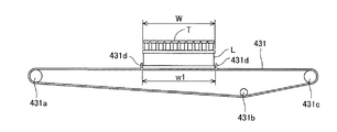
ここで図6〜図8を参照してラック搬送部43の構成を詳細に説明する。図6に示すように、ラック搬送部43は、それぞれ独立して動作可能な第1ベルト431及び第2ベルト432の2つのベルトを有している。また、第1ベルト431及び第2ベルト432の矢印Y方向の幅b1は、それぞれサンプルラックLの矢印Y方向の幅Bの半分以下の大きさである。かかる第1ベルト431及び第2ベルト432は、ラック搬送部43がサンプルラックLを搬送するときにサンプルラックLの幅Bからはみ出ないように並列に配置されている。図7は、第1ベルト431の構成を示す正面図であり、図8は、第2ベルト432の構成を示す正面図である。図7及び図8に示すように、第1ベルト431及び第2ベルト432は、それぞれ環状に形成されており、第1ベルト431はローラ431a〜431cを取り囲むように配置され、第2ベルト432はローラ432a〜432cを取り囲むように配置されている。また、第1ベルト431の外周部には、サンプルラックLのX方向の幅Wよりも若干(例えば、1mm)大きい内幅w1を有するように2つの突起片431dが設けられており、同様に、図8に示すように、第2ベルト432の外周部には、前記内幅w1と同程度の内幅w2を有するように2つの突起片432dが設けられている。第1ベルト431は、2つの突起片431dの内側にサンプルラックLを保持した状態において、ステッピングモータ(図示せず)によりローラ431a〜431cの外周を移動されることによって、サンプルラックLを矢印X方向に移動するように構成されている。第2ベルト432は、2つの突起片432dの内側にサンプルラックLを保持した状態において、ステッピングモータ(図示せず)によりローラ432a〜432cの外周を移動されることによって、サンプルラックLを矢印X方向に移動するように構成されている。また、第1ベルト431及び第2ベルト432は、互いに独立してサンプルラックLを移送可能に構成されている。これにより、ラック搬送部43は、第1検体供給位置43a、第2検体供給位置43b、及び、バーコード読取部44が検体容器TのバーコードラベルBL1に印刷されたバーコードを読み取るための読取位置43dまで検体が搬送されるようにサンプルラックLを搬送することが可能である。   Here, the configuration of the rack transport unit 43 will be described in detail with reference to FIGS. As shown in FIG. 6, the rack transport unit 43 has two belts, a first belt 431 and a second belt 432, which can operate independently. In addition, the width b1 of the first belt 431 and the second belt 432 in the arrow Y direction is less than half the width B of the sample rack L in the arrow Y direction. The first belt 431 and the second belt 432 are arranged in parallel so as not to protrude from the width B of the sample rack L when the rack transport unit 43 transports the sample rack L. FIG. 7 is a front view showing the configuration of the first belt 431, and FIG. 8 is a front view showing the configuration of the second belt 432. As shown in FIGS. 7 and 8, the first belt 431 and the second belt 432 are each formed in an annular shape, the first belt 431 is disposed so as to surround the rollers 431a to 431c, and the second belt 432 is It arrange | positions so that the rollers 432a-432c may be surrounded. Further, the outer periphery of the first belt 431 is provided with two projecting pieces 431d having an inner width w1 slightly larger (for example, 1 mm) than the width W in the X direction of the sample rack L. Similarly, As shown in FIG. 8, two projecting pieces 432 d are provided on the outer periphery of the second belt 432 so as to have an inner width w <b> 2 that is approximately the same as the inner width w <b> 1. The first belt 431 moves the outer periphery of the rollers 431a to 431c by a stepping motor (not shown) while holding the sample rack L inside the two protruding pieces 431d, thereby moving the sample rack L to the arrow X. Configured to move in the direction. The second belt 432 moves the outer periphery of the rollers 432a to 432c by a stepping motor (not shown) while holding the sample rack L inside the two protruding pieces 432d, thereby moving the sample rack L to the arrow X. Configured to move in the direction. The first belt 431 and the second belt 432 are configured to be able to transfer the sample rack L independently of each other. Thereby, the rack transport unit 43 reads the first sample supply position 43a, the second sample supply position 43b, and the barcode reading unit 44 for reading the barcode printed on the barcode label BL1 of the sample container T. The sample rack L can be transported so that the sample is transported to the position 43d.

図4に戻り、バーコード読取部44は、図2に示した検体容器TのバーコードラベルBL1に印刷されたバーコードを読み取り、またサンプルラックLに貼付されたバーコードラベルBL2に印刷されたバーコードを読み取るように構成されている。また、バーコード読取部44は、図示しない回転装置によって対象の検体容器TをサンプルラックLに収容したまま水平方向に回転させながら検体容器Tのバーコードを読み取るように構成されている。これにより、検体容器Tのバーコードがバーコード読取部44に対して反対側に貼付されている場合にも、検体容器Tを回転させることによって、バーコードをバーコード読取部44側に向けることが可能である。また、サンプルラックLのバーコードラベルBL2に印刷されたバーコードは、各ラックに固有に付されたものであり、検体の分析結果の管理などに使用される。   Returning to FIG. 4, the barcode reading unit 44 reads the barcode printed on the barcode label BL1 of the sample container T shown in FIG. 2 and prints it on the barcode label BL2 attached to the sample rack L. It is configured to read barcodes. The barcode reading unit 44 is configured to read the barcode of the sample container T while rotating the target sample container T in the horizontal direction while being accommodated in the sample rack L by a rotating device (not shown). Thereby, even when the barcode of the sample container T is affixed to the opposite side with respect to the barcode reading unit 44, the barcode is directed to the barcode reading unit 44 side by rotating the sample container T. Is possible. Further, the barcode printed on the barcode label BL2 of the sample rack L is uniquely attached to each rack, and is used for managing the analysis result of the specimen.

検体容器センサ45a,45bは、接触型のセンサであり、のれん形状の接触片、光を出射する発光素子、及び受光素子(図示せず)を有している。検体容器センサ45a,45bは、接触片が検出対象の被検出物に当接することにより屈曲され、その結果、発光素子から出射された光が接触片により反射されて受光素子に入射するように構成されている。これにより検体容器センサ45a,45bの下方をサンプルラックLに収容された検出対象の検体容器Tが通過する際に、接触片が検体容器Tにより屈曲されて、検体容器Tを検出することが可能である。検体容器センサ45aは、第1検体供給位置43aに設けられており、検体容器センサ45bは、第2検体供給位置43bに設けられている。これにより、第1検体供給位置43aにおける検体容器Tの有無を検体容器センサ45aで検出し、第2検体供給位置43bにおける検体容器Tの有無を検体容器センサ45bで検出することができる。   The specimen container sensors 45a and 45b are contact-type sensors, and have a goodwill-shaped contact piece, a light emitting element that emits light, and a light receiving element (not shown). The specimen container sensors 45a and 45b are configured such that the contact piece is bent by abutting against the detection target object, and as a result, the light emitted from the light emitting element is reflected by the contact piece and enters the light receiving element. Has been. As a result, when the sample container T to be detected housed in the sample rack L passes below the sample container sensors 45a and 45b, the contact piece is bent by the sample container T and the sample container T can be detected. It is. The sample container sensor 45a is provided at the first sample supply position 43a, and the sample container sensor 45b is provided at the second sample supply position 43b. Thereby, the presence or absence of the sample container T at the first sample supply position 43a can be detected by the sample container sensor 45a, and the presence or absence of the sample container T at the second sample supply position 43b can be detected by the sample container sensor 45b.

ラック搬送部43の搬送方向下流側端には、後述する分析後ラック保持部42が設けられており、この分析後ラック保持部42の後方にラック送出部45が設けられている。かかるラック送出部45は、図示しないステッピングモータの駆動力により矢印Y方向に水平に直線移動するように構成されている。これにより、分析後ラック保持部42とラック送出部45との間の位置451(以下、「分析後ラック送出位置」という。)にサンプルラックLが搬送された場合に、ラック送出部45を分析後ラック保持部42側に移動することによって、サンプルラックLを押動させて分析後ラック保持部42内に移動することが可能である。   A post-analysis rack holding unit 42, which will be described later, is provided at the downstream end of the rack transport unit 43 in the carrying direction, and a rack delivery unit 45 is provided behind the post-analysis rack holding unit 42. The rack delivery unit 45 is configured to linearly move horizontally in the arrow Y direction by a driving force of a stepping motor (not shown). Thus, when the sample rack L is transported to a position 451 between the after-analysis rack holding unit 42 and the rack sending unit 45 (hereinafter referred to as “after-analysis rack sending position”), the rack sending unit 45 is analyzed. By moving to the rear rack holding unit 42 side, the sample rack L can be pushed and moved into the post-analysis rack holding unit 42.

分析後ラック保持部42は、平面視において四角形をなしており、その幅はサンプルラックLの幅より若干大きくなっている。この分析後ラック保持部42は、周囲の面よりも一段低く形成されており、その上面に分析が完了したサンプルラックLが載置される。分析後ラック保持部42は、上記のラック搬送部43に連なっており、上述したように、ラック送出部45によって、ラック搬送部43からサンプルラックLが送り込まれるようになっている。   The post-analysis rack holding portion 42 has a quadrangular shape in plan view, and its width is slightly larger than the width of the sample rack L. The post-analysis rack holder 42 is formed one step lower than the surrounding surface, and the sample rack L that has been analyzed is placed on the upper surface thereof. The post-analysis rack holding unit 42 is connected to the rack transport unit 43, and the sample rack L is sent from the rack transport unit 43 by the rack delivery unit 45 as described above.

上記のような構成とすることにより、検体搬送ユニット4は、分析前ラック保持部41に載置されたサンプルラックLをラック搬送部43へと移送し、さらにラック搬送部43によって搬送することにより、検体を第1測定ユニット2又は第2測定ユニット3へと供給することができる。また、吸引が完了した検体を収容するサンプルラックLは、ラック搬送部43により、分析後ラック送出位置(図示せず)へと移送され、ラック送出部45により分析後ラック保持部42へ送出される。複数のサンプルラックLが分析前ラック保持部41に載置された場合では、分析が完了した検体を収容するサンプルラックLが次々にラック送出部45により分析後ラック保持部42へと送出され、これらの複数のサンプルラックLが分析後ラック保持部42に貯留されることとなる。   With the above-described configuration, the sample transport unit 4 transfers the sample rack L placed on the pre-analysis rack holding unit 41 to the rack transport unit 43 and further transports it by the rack transport unit 43. The specimen can be supplied to the first measurement unit 2 or the second measurement unit 3. Further, the sample rack L containing the sample that has been aspirated is transferred to the post-analysis rack delivery position (not shown) by the rack transport unit 43 and sent to the post-analysis rack holding unit 42 by the rack delivery unit 45. The In the case where a plurality of sample racks L are placed on the pre-analysis rack holding unit 41, the sample racks L that contain the samples for which analysis has been completed are successively sent to the post-analysis rack holding unit 42 by the rack sending unit 45, The plurality of sample racks L are stored in the post-analysis rack holding unit 42.

<情報処理ユニットの構成>
次に、情報処理ユニット5の構成について説明する。情報処理ユニット5は、コンピュータにより構成されている。図9は、情報処理ユニット5の構成を示すブロック図である。情報処理ユニット5は、コンピュータ5aによって実現される。図9に示すように、コンピュータ5aは、本体51と、画像表示部52と、入力部53とを備えている。本体51は、CPU51a、ROM51b、RAM51c、ハードディスク51d、読出装置51e、入出力インタフェース51f、通信インタフェース51g、及び画像出力インタフェース51hを備えており、CPU51a、ROM51b、RAM51c、ハードディスク51d、読出装置51e、入出力インタフェース51f、通信インタフェース51g、及び画像出力インタフェース51hは、バス51jによって接続されている。
<Configuration of information processing unit>
Next, the configuration of the information processing unit 5 will be described. The information processing unit 5 is configured by a computer. FIG. 9 is a block diagram showing a configuration of the information processing unit 5. The information processing unit 5 is realized by a computer 5a. As shown in FIG. 9, the computer 5 a includes a main body 51, an image display unit 52, and an input unit 53. The main body 51 includes a CPU 51a, a ROM 51b, a RAM 51c, a hard disk 51d, a reading device 51e, an input / output interface 51f, a communication interface 51g, and an image output interface 51h. The output interface 51f, the communication interface 51g, and the image output interface 51h are connected by a bus 51j.

CPU51aは、RAM51cにロードされたコンピュータプログラムを実行することが可能である。そして、後述するような検体分析用並びに第1測定ユニット2、第2測定ユニット3及び検体搬送ユニット4の制御用のコンピュータプログラム54aを当該CPU51aが実行することにより、コンピュータ5aが情報処理ユニット5として機能する。   The CPU 51a can execute a computer program loaded in the RAM 51c. Then, the CPU 5a executes the computer program 54a for sample analysis and control of the first measurement unit 2, the second measurement unit 3, and the sample transport unit 4 as will be described later, so that the computer 5a becomes the information processing unit 5. Function.

ROM51bは、マスクROM、PROM、EPROM、又はEEPROM等によって構成されており、CPU51aに実行されるコンピュータプログラム及びこれに用いるデータ等が記録されている。   The ROM 51b is configured by a mask ROM, PROM, EPROM, EEPROM, or the like, and stores a computer program executed by the CPU 51a, data used for the same, and the like.

RAM51cは、SRAMまたはDRAM等によって構成されている。RAM51cは、ハードディスク51dに記録されているコンピュータプログラム54aの読み出しに用いられる。また、CPU51aがコンピュータプログラムを実行するときに、CPU51aの作業領域として利用される。   The RAM 51c is configured by SRAM, DRAM, or the like. The RAM 51c is used for reading the computer program 54a recorded on the hard disk 51d. Further, when the CPU 51a executes a computer program, it is used as a work area for the CPU 51a.

RAM51cには、第1測定ユニット2及び第2測定ユニット3の状態をそれぞれ示す測定ユニット状態データ領域S1及びS2が設けられている。かかる測定ユニット状態データ領域S1,S2には、「検体取込可」及び「検体取込不可」の何れか一方のデータが保持される。ここで、測定ユニットが検体容器の取込動作、測定試料の調製動作及び測定試料中の血球の検出動作等の測定動作を行っておらず、検体容器の取込を待機しているスタンバイ状態のときには、その測定ユニットの状態は「検体取込可」とされる。また、測定ユニットが検体容器の取込動作、検体容器からの検体の吸引動作、測定ユニットからの検体容器の排出動作を行っているときには、その測定ユニットの状態は「検体取込不可」とされる。さらに、測定ユニットが、測定試料の調製動作、検出部23,33による測定試料中の血球の検出動作及び洗浄動作を行っているときには、その測定ユニットの状態は新たな検体の取込が可能な「検体取込可」とされる。   The RAM 51c is provided with measurement unit state data areas S1 and S2 indicating the states of the first measurement unit 2 and the second measurement unit 3, respectively. In the measurement unit state data areas S1 and S2, data of either “sample loading possible” or “sample loading impossible” is held. Here, the measurement unit is not performing a measurement operation such as a sample container taking-in operation, a measurement sample preparing operation, or a blood cell detection operation in the measurement sample, and is in a standby state waiting for taking in the sample container. In some cases, the state of the measurement unit is “sample ready”. In addition, when the measurement unit is performing a sample container taking operation, a sample aspirating operation from the sample container, or a sample container ejecting operation from the measurement unit, the state of the measurement unit is set to “sample cannot be taken in”. The Furthermore, when the measurement unit is performing a measurement sample preparation operation, a blood cell detection operation and a washing operation in the measurement sample by the detection units 23 and 33, the measurement unit can take in a new sample. “Specimen loading is possible”.

また、RAM51cには、第1測定ユニット2及び第2測定ユニット3の状態データを蓄積する状態キューQ1及びQ2の領域が設けられている。かかる状態キューQ1及びQ2は、第1測定ユニット2及び第2測定ユニット3の状態データをリアルタイムに受け付け、状態データを先入れ先出し形式のリスト構造で保持する。   The RAM 51c is provided with status queues Q1 and Q2 for storing status data of the first measurement unit 2 and the second measurement unit 3. The status queues Q1 and Q2 receive the status data of the first measurement unit 2 and the second measurement unit 3 in real time and hold the status data in a first-in first-out list structure.

ハードディスク51dは、オペレーティングシステム及びアプリケーションプログラム等、CPU51aに実行させるための種々のコンピュータプログラム及び当該コンピュータプログラムの実行に用いられるデータがインストールされている。後述するコンピュータプログラム54aも、このハードディスク51dにインストールされている。   The hard disk 51d is installed with various computer programs to be executed by the CPU 51a, such as an operating system and application programs, and data used for executing the computer programs. A computer program 54a described later is also installed in the hard disk 51d.

また、ハードディスク51dには、第1測定ユニット2によって測定可能な測定項目を特定する第1測定項目特定情報55a、及び第2測定ユニット3によって測定可能な測定項目を特定する第2測定項目特定情報55bが格納されている。つまり、第1測定項目特定情報55aは、第1測定ユニット2では、WBC、RBC、PLT、HGB、NEUT、LYMPH、EO、BASO、及びMONOを含むCBC+DIFF項目が測定可能であることを示す情報であり、第2測定項目特定情報55bは、第2測定ユニット3では上記CBC+DIFF項目に加えNRBC及びRETが測定可能であることを示す情報である。CPU51aは、後述するように検体を第1測定ユニット2及び第2測定ユニット3に割り振るときに、第1測定項目特定情報55a及び第2測定項目特定情報55bを使用して検体の割り振りを実行する。例えば、測定オーダに含まれる測定項目がCBC+DIFF項目である検体は、第1測定項目特定情報55aから第1測定ユニット2によって測定可能であり、第2測定項目特定情報55bから第2測定ユニット3によっても測定可能であることが分かる。ここから、当該検体は第1測定ユニット2及び第2測定ユニット3の何れかに振り分けられる。また、測定オーダに含まれる測定項目がNRBCを含んでいる場合には、第1測定項目特定情報55aから第1測定ユニット2によって測定することはできず、第2測定項目特定情報55bから第2測定ユニット3によって測定可能であることが分かる。ここから、当該検体は第2測定ユニット3に振り分けられる。   The hard disk 51d includes first measurement item specifying information 55a for specifying measurement items that can be measured by the first measurement unit 2, and second measurement item specifying information for specifying measurement items that can be measured by the second measurement unit 3. 55b is stored. In other words, the first measurement item specifying information 55a is information indicating that the first measurement unit 2 can measure CBC + DIFF items including WBC, RBC, PLT, HGB, NEUT, LYMPH, EO, BASO, and MONO. The second measurement item specifying information 55b is information indicating that the second measurement unit 3 can measure NRBC and RET in addition to the CBC + DIFF item. As will be described later, the CPU 51a uses the first measurement item specifying information 55a and the second measurement item specifying information 55b to execute sample allocation when allocating the sample to the first measurement unit 2 and the second measurement unit 3. . For example, a sample whose measurement item included in the measurement order is a CBC + DIFF item can be measured by the first measurement unit 2 from the first measurement item identification information 55a, and can be measured by the second measurement unit 3 from the second measurement item identification information 55b. It can be seen that measurement is also possible. From here, the sample is distributed to either the first measurement unit 2 or the second measurement unit 3. When the measurement item included in the measurement order includes NRBC, measurement cannot be performed by the first measurement unit 2 from the first measurement item specifying information 55a, and the second measurement item specifying information 55b to the second can be measured. It can be seen that measurement is possible by the measurement unit 3. From here, the sample is distributed to the second measurement unit 3.

読出装置51eは、フレキシブルディスクドライブ、CD−ROMドライブ、またはDVD−ROMドライブ等によって構成されており、可搬型記録媒体54に記録されたコンピュータプログラムまたはデータを読み出すことができる。また、可搬型記録媒体54には、コンピュータを情報処理ユニット5として機能させるためのコンピュータプログラム54aが格納されており、コンピュータ5aが当該可搬型記録媒体54からコンピュータプログラム54aを読み出し、当該コンピュータプログラム54aをハードディスク51dにインストールすることが可能である。   The reading device 51e is configured by a flexible disk drive, a CD-ROM drive, a DVD-ROM drive, or the like, and can read a computer program or data recorded on the portable recording medium 54. The portable recording medium 54 stores a computer program 54a for causing the computer to function as the information processing unit 5. The computer 5a reads the computer program 54a from the portable recording medium 54, and the computer program 54a. Can be installed on the hard disk 51d.

なお、前記コンピュータプログラム54aは、可搬型記録媒体54によって提供されるのみならず、電気通信回線(有線、無線を問わない)によってコンピュータ5aと通信可能に接続された外部の機器から前記電気通信回線を通じて提供することも可能である。例えば、前記コンピュータプログラム54aがインターネット上のサーバコンピュータのハードディスク内に格納されており、このサーバコンピュータにコンピュータ5aがアクセスして、当該コンピュータプログラムをダウンロードし、これをハードディスク51dにインストールすることも可能である。   The computer program 54a is not only provided by the portable recording medium 54, but also from an external device that is communicably connected to the computer 5a via an electric communication line (whether wired or wireless). It is also possible to provide through. For example, the computer program 54a is stored in the hard disk of a server computer on the Internet. The computer 5a can access the server computer, download the computer program, and install it on the hard disk 51d. is there.

また、ハードディスク51dには、例えば米マイクロソフト社が製造販売するWindows(登録商標)等のマルチタスクオペレーティングシステムがインストールされている。以下の説明においては、本実施の形態に係るコンピュータプログラム54aは当該オペレーティングシステム上で動作するものとしている。   The hard disk 51d is installed with a multitask operating system such as Windows (registered trademark) manufactured and sold by Microsoft Corporation. In the following description, it is assumed that the computer program 54a according to the present embodiment operates on the operating system.

入出力インタフェース51fは、例えばUSB,IEEE1394,又はRS-232C等のシリアルインタフェース、SCSI,IDE,又は IEEE1284等のパラレルインタフェース、及びD/A変換器、A/D変換器等からなるアナログインタフェース等から構成されている。入出力インタフェース51fには、キーボード及びマウスからなる入力部53が接続されており、ユーザが当該入力部53を使用することにより、コンピュータ5aにデータを入力することが可能である。また、入出力インタフェース51fは、第1測定ユニット2、第2測定ユニット3、及び検体搬送ユニット4に接続されている。これにより、情報処理ユニット5は、第1測定ユニット2、第2測定ユニット3、及び検体搬送ユニット4のそれぞれを制御可能となっている。   The input / output interface 51f is, for example, a serial interface such as USB, IEEE1394, or RS-232C, a parallel interface such as SCSI, IDE, or IEEE1284, and an analog interface including a D / A converter, an A / D converter, or the like. It is configured. An input unit 53 including a keyboard and a mouse is connected to the input / output interface 51f, and the user can input data to the computer 5a by using the input unit 53. The input / output interface 51 f is connected to the first measurement unit 2, the second measurement unit 3, and the sample transport unit 4. As a result, the information processing unit 5 can control each of the first measurement unit 2, the second measurement unit 3, and the sample transport unit 4.

通信インタフェース51gは、Ethernet(登録商標)インタフェースである。通信インタフェース51gはLANを介してホストコンピュータ6に接続されている。コンピュータ5aは、通信インタフェース51gにより、所定の通信プロトコルを使用して当該LANに接続されたホストコンピュータ6との間でデータの送受信が可能である。   The communication interface 51g is an Ethernet (registered trademark) interface. The communication interface 51g is connected to the host computer 6 via a LAN. The computer 5a can transmit and receive data to and from the host computer 6 connected to the LAN using a predetermined communication protocol by the communication interface 51g.

画像出力インタフェース51hは、LCDまたはCRT等で構成された画像表示部52に接続されており、CPU51aから与えられた画像データに応じた映像信号を画像表示部52に出力するようになっている。画像表示部52は、入力された映像信号にしたがって、画像(画面)を表示する。   The image output interface 51h is connected to an image display unit 52 constituted by an LCD, a CRT, or the like, and outputs a video signal corresponding to the image data given from the CPU 51a to the image display unit 52. The image display unit 52 displays an image (screen) according to the input video signal.

[検体分析装置1の動作]
以下、本実施の形態に係る検体分析装置1の動作について説明する。
[Operation of Sample Analyzer 1]
Hereinafter, the operation of the sample analyzer 1 according to the present embodiment will be described.

<検体搬送制御処理>
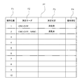
図10は、検体分析装置1の情報処理ユニット5による検体搬送制御処理の流れを示すフローチャートである。オペレータは、検体を収容した検体容器Tを複数保持するサンプルラックLを分析前ラック保持部41に載置する。この状態で、オペレータは入力部53を操作し、情報処理ユニット5に検体測定の実行を指示する。情報処理ユニット5のCPU51aは、検体測定の実行指示を受け付けた後、以下の検体搬送制御処理を実行する。まずCPU51aは、図示しないセンサにより分析前ラック保持部41に載置されたサンプルラックLを検出すると(ステップS101)、RAM51cに検体の測定に用いられる検体処理テーブルの領域を確保する(ステップS102)。図11は、検体処理テーブルの構造を示す模式図である。検体処理テーブルPTは、サンプルラックL毎に、各検体のサンプルラックLでの保持位置、測定オーダ、検体の測定状況、検体の測定優先順位を保持するテーブルである。図11に示すように、検体処理テーブルPTには、10個の行が設けられており、各行はサンプルラックLに収容されている検体にそれぞれ対応している。かかる検体処理テーブルPTには、サンプルラックLでの保持位置のフィールド(列)F1と、測定オーダのフィールドF2と、測定状況のフィールドF3と、優先順位のフィールドF4とが設けられている。フィールドF1には、検体のサンプルラックLでの保持位置を示す「1」〜「10」の情報が格納される。フィールドF2には、後述する測定オーダに示される測定項目の情報(CBC+DIFF項目を示す情報、CBC+DIFF項目及びNRBCを示す情報等)が格納される。なお、上述したように、CBC+DIFF項目は、WBC、RBC、PLT、HGB、NEUT、LYMPH、EO、BASO、及びMONOの各測定項目を含んでいるため、これらの測定項目の情報をそれぞれ個別にフィールドF2に格納してもよいし、図11に示すように「CBC+DIFF」を示す情報をフィールドF2に格納してもよい。フィールドF3には、測定状況を示す情報として、「未測定」、「再検待ち」、「測定済」の3種類の情報の何れかが格納される。フィールドF4には、優先順位を示す「1」〜「10」の情報が格納される。ステップS102では、検体処理テーブルPTのフィールドF1を除く各セルは全て空欄(何も情報が格納されていない)状態である。
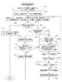
<Sample transport control processing>
FIG. 10 is a flowchart showing the flow of the sample transport control process by the information processing unit 5 of the sample analyzer 1. The operator places the sample rack L holding a plurality of sample containers T containing the sample on the pre-analysis rack holding unit 41. In this state, the operator operates the input unit 53 to instruct the information processing unit 5 to execute sample measurement. After receiving the sample measurement execution instruction, the CPU 51a of the information processing unit 5 executes the following sample transport control process. First, when the CPU 51a detects the sample rack L placed on the pre-analysis rack holding unit 41 by a sensor (not shown) (step S101), the CPU 51a secures an area of the sample processing table used for sample measurement in the RAM 51c (step S102). . FIG. 11 is a schematic diagram showing the structure of the sample processing table. The sample processing table PT is a table that holds, for each sample rack L, the holding position of each sample in the sample rack L, the measurement order, the measurement status of the sample, and the measurement priority order of the sample. As shown in FIG. 11, the sample processing table PT is provided with 10 rows, and each row corresponds to a sample stored in the sample rack L. The sample processing table PT includes a holding position field (column) F1 in the sample rack L, a measurement order field F2, a measurement status field F3, and a priority field F4. In the field F1, information “1” to “10” indicating the holding position of the sample in the sample rack L is stored. The field F2 stores measurement item information (information indicating a CBC + DIFF item, information indicating a CBC + DIFF item and NRBC, etc.) indicated in a measurement order to be described later. As described above, since the CBC + DIFF item includes the measurement items WBC, RBC, PLT, HGB, NEUT, LYMPH, EO, BASO, and MONO, the information of these measurement items is individually fielded. The information indicating “CBC + DIFF” may be stored in the field F2, as shown in FIG. In the field F3, any one of three types of information “unmeasured”, “waiting for re-examination”, and “measured” is stored as information indicating the measurement status. Information “1” to “10” indicating the priority order is stored in the field F4. In step S102, all cells except the field F1 of the sample processing table PT are all blank (no information is stored).

次に、CPU51aは、状態キューQ1,Q2を参照し、その時点における第1測定ユニット2及び第2測定ユニット3の状態を示すデータを測定ユニット状態データ領域S1,S2に格納する(ステップS103)。ここで、状態キューQ1,Q2には複数の状態データが蓄積されている場合がある。このような場合には、CPU51aは、状態キューQ1,Q2から状態データを順次取り出し、最後に取り出されたデータを測定ユニット状態データ領域S1,S2に格納する。状態キューQ1,Q2から最後に取り出されたデータは、第1測定ユニット2及び第2測定ユニット3の最新の状態を示すものであり、つまり、その時点における第1測定ユニット2及び第2測定ユニット3の状態を示している。なお、状態キューQ1,Q2の初期値は「検体取込可」である。   Next, the CPU 51a refers to the state queues Q1 and Q2, and stores data indicating the states of the first measurement unit 2 and the second measurement unit 3 at that time in the measurement unit state data areas S1 and S2 (step S103). . Here, a plurality of state data may be accumulated in the state queues Q1 and Q2. In such a case, the CPU 51a sequentially extracts the state data from the state queues Q1 and Q2, and stores the last extracted data in the measurement unit state data areas S1 and S2. The last data retrieved from the status queues Q1 and Q2 indicates the latest state of the first measurement unit 2 and the second measurement unit 3, that is, the first measurement unit 2 and the second measurement unit at that time. 3 is shown. Note that the initial value of the status queues Q1 and Q2 is “specimen uptake”.

次に、CPU51aは、検体処理テーブルPTにおいて全検体の測定状況が「測定済」か否かを判定する(ステップS104)。ステップS104において測定状況が「測定済」ではない検体が存在する場合には(ステップS104においてNO)、CPU51aは、検体処理テーブルPTを参照して要処理検体が存在するか否かを判定する(ステップS105)。この「要処理検体」とは、測定オーダが確定済であり、且つ、未測定又は再検待ちの検体のことを指している。つまり、検体処理テーブルPTにおいて、フィールドF2に測定オーダの情報が格納されており、フィールドF4に「未測定」又は「再検待ち」の情報が格納されている検体が「要処理検体」である。ステップS105において要処理検体が存在しない場合には(ステップS105においてNO)、CPU51aは、検体処理テーブルPTを参照して、測定オーダが未確定の検体、即ち、フィールドF2に測定オーダの情報が格納されていない検体が存在するか否かを判定する(ステップS106)。   Next, the CPU 51a determines whether or not the measurement status of all the samples is “measured” in the sample processing table PT (step S104). If there is a sample whose measurement status is not “measured” in step S104 (NO in step S104), the CPU 51a refers to the sample processing table PT to determine whether or not there is a sample to be processed (step S104). Step S105). This “sample to be processed” refers to a sample for which the measurement order has been confirmed and which has not been measured or is waiting for reexamination. That is, in the sample processing table PT, the information on the measurement order is stored in the field F2, and the sample in which the information “Unmeasured” or “Waiting for retest” is stored in the field F4 is “Needs to be processed”. When there is no sample to be processed in step S105 (NO in step S105), the CPU 51a refers to the sample processing table PT, and stores the information on the measurement order in the sample for which the measurement order has not been determined, that is, the field F2. It is determined whether or not there is an untreated sample (step S106).

ステップS106において測定オーダが未確定の検体が存在する場合には(ステップS106においてYES)、CPU51aは、検体搬送ユニット4を制御してサンプルラックLを搬送し、当該サンプルラックLに収容されている検体の内、測定オーダが未確定の検体の検体容器Tの1つを、バーコード読取部44の前側の読取位置43dに位置させる(ステップS107)。ここで、読取位置43dに搬送される検体としては、検体処理テーブルPTにおいてフィールドF2に測定オーダの情報が格納されていない検体の内、最も保持位置の番号が小さい検体(サンプルラックLの搬送方向において最も下流側に位置する検体)が選択される。つまり、測定オーダが確定している検体が全くない場合は、保持位置が「1」の検体が選択される。また、保持位置が「1」の検体以外の全ての検体の測定オーダが未確定の場合は、保持位置が「2」の検体が選択される。このように、保持位置の番号が小さい検体から順に選択されることになる。   If there is a sample whose measurement order is not confirmed in step S106 (YES in step S106), the CPU 51a controls the sample transport unit 4 to transport the sample rack L and is stored in the sample rack L. Of the samples, one of the sample containers T for which the measurement order has not been determined is positioned at the reading position 43d on the front side of the barcode reading unit 44 (step S107). Here, as the sample transported to the reading position 43d, the sample with the smallest holding position number (the transport direction of the sample rack L) among the samples in which the measurement order information is not stored in the field F2 in the sample processing table PT. The most downstream sample) is selected. That is, when there is no sample for which the measurement order is confirmed, the sample with the holding position “1” is selected. In addition, when the measurement order of all the samples other than the sample whose holding position is “1” is unconfirmed, the sample whose holding position is “2” is selected. In this way, the samples with the smallest holding position numbers are selected in order from the smallest.

CPU51aは、選択された検体を読取位置43dに搬送すると、当該検体のバーコードから検体IDをバーコード読取部44により読み取らせて(ステップS108)、当該検体IDに対応する測定オーダをホストコンピュータ6へ問い合わせる(ステップS109)。これは、ネットワークを通じて接続されているホストコンピュータ6へ検体IDを含む測定オーダ要求データを送信することにより行われる。CPU51aは、測定オーダの受信を待機し(ステップS110においてNO)、測定オーダを受信すると(ステップS110においてYES)、その測定オーダを当該検体IDと対応付けて検体処理テーブルPTに格納して検体処理テーブルPTを更新する(ステップS111)。   When the selected sample is conveyed to the reading position 43d, the CPU 51a causes the barcode reading unit 44 to read the sample ID from the barcode of the sample (step S108), and the host computer 6 displays the measurement order corresponding to the sample ID. (Step S109). This is performed by transmitting measurement order request data including the sample ID to the host computer 6 connected through the network. The CPU 51a waits for the reception of the measurement order (NO in step S110). When the measurement order is received (YES in step S110), the measurement order is stored in the sample processing table PT in association with the sample ID. The table PT is updated (step S111).

次に、CPU51aは、要処理検体の優先順位を決定する(ステップS112)。この処理では、以下のルールにしたがって、各要処理検体の優先順位が決定される。
ルール1:測定オーダに第2測定項目であるRET又はNRBCが含まれている要処理検体は、測定オーダに第1測定項目であるCBC+DIFF項目のみが含まれる検体よりも優先順位が高い。
ルール2:サンプルラックLの先頭側(搬送方向下流側)にある要処理検体は、サンプルラックLの後尾側(搬送方向上流側)にある要処理検体よりも優先順位が高い。
なお、ステップS112において、1つしか要処理検体が存在していない場合は、その検体の優先順位を1に設定し、その他の検体の優先順位は決定しない。このようにして決定された検体の優先順位は、検体処理テーブルPTに格納される。CPU51aは、かかるステップS112の処理を完了すると、ステップS103へと処理を戻す。
Next, the CPU 51a determines the priority order of samples to be processed (step S112). In this process, the priority of each sample to be processed is determined according to the following rules.
Rule 1: A sample requiring processing in which RET or NRBC that is the second measurement item is included in the measurement order has a higher priority than a sample in which only the CBC + DIFF item that is the first measurement item is included in the measurement order.
Rule 2: The sample to be processed on the front side (downstream in the transport direction) of the sample rack L has a higher priority than the sample to be processed on the rear side (upstream in the transport direction) of the sample rack L.
In step S112, when there is only one sample to be processed, the priority of the sample is set to 1, and the priority of other samples is not determined. The priority order of the sample determined in this way is stored in the sample processing table PT. When completing the process in step S112, the CPU 51a returns the process to step S103.

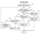
一方、上記ステップS105において要処理検体が存在する場合には(ステップS105においてYES)、CPU51aは、検体搬送先決定処理を実行する(ステップS113)。図12は、検体搬送先決定処理の手順を示すフローチャートである。検体搬送先決定処理においては、まずCPU51aは、検体処理テーブルPTを参照して、優先順位が1位の検体を選択する(ステップS201)。次にCPU51aは、選択された検体の測定オーダに第2測定項目であるRET又はNRBC項目が含まれているか否かを判別する(ステップS202)。   On the other hand, when there is a sample to be processed in step S105 (YES in step S105), the CPU 51a executes a sample transport destination determination process (step S113). FIG. 12 is a flowchart illustrating the procedure of the sample transport destination determination process. In the sample transport destination determination process, first, the CPU 51a refers to the sample processing table PT and selects the sample with the first priority (step S201). Next, the CPU 51a determines whether or not the RET or NRBC item that is the second measurement item is included in the measurement order of the selected sample (step S202).

ステップS202において、選択された検体の測定オーダにRET又はNRBC項目が含まれている場合には(ステップS202においてYES)、CPU51aは、RAM51cの測定ユニット状態データ領域S2を参照し、第2測定ユニット3の状態が「検体取込可」であるか否かを判別する(ステップS203)。ステップS203において、第2測定ユニット3の状態が「検体取込可」である場合には(ステップS203においてYES)、CPU51aは、第2測定ユニット3を搬送先に決定し(ステップS204)、処理を検体搬送先決定処理の呼出アドレスへリターンする。   In step S202, when the RET or NRBC item is included in the measurement order of the selected sample (YES in step S202), the CPU 51a refers to the measurement unit state data area S2 of the RAM 51c, and the second measurement unit. It is determined whether or not the state 3 is “specimen uptake” (step S203). In step S203, when the state of the second measurement unit 3 is “sample ready” (YES in step S203), the CPU 51a determines the second measurement unit 3 as a transport destination (step S204) and performs processing. Is returned to the calling address of the sample transport destination determination process.

一方、ステップS203において、第2測定ユニット3の状態が「検体取込不可」である場合には(ステップS203においてNO)、CPU51aは、全ての優先順位の検体が選択されたか否か、即ち、要処理検体の全てが選択されたか否かを判別する(ステップS205)。ステップS205において、未選択の要処理検体が存在する場合には(ステップS205においてNO)、CPU51aは、次の優先順位の検体を選択し(ステップS206)、処理をステップS202へと移す。   On the other hand, when the state of the second measurement unit 3 is “sample incapable” in step S203 (NO in step S203), the CPU 51a determines whether or not all the prioritized samples have been selected, that is, It is determined whether all the samples requiring processing have been selected (step S205). In step S205, when there is an unselected sample to be processed (NO in step S205), the CPU 51a selects the sample with the next priority (step S206), and moves the process to step S202.

また、ステップS205において、未選択の要処理検体が存在しない場合には(ステップS205においてYES)、CPU51aは、搬送先を「なし」と決定し(ステップS207)、処理を検体搬送先決定処理の呼出アドレスへリターンする。   If there is no unselected sample to be processed in step S205 (YES in step S205), the CPU 51a determines “None” as the transport destination (step S207), and the process is a sample transport destination determination process. Return to the calling address.

ステップS202において、選択された検体の測定オーダにRET又はNRBC項目が含まれていない場合には(ステップS202においてNO)、CPU51aは、RAM51cの測定ユニット状態データ領域S1を参照し、第1測定ユニット2の状態が「検体取込可」であるか否かを判別する(ステップS208)。ステップS208において、第1測定ユニット2の状態が「検体取込可」である場合には(ステップS208においてYES)、CPU51aは、第1測定ユニット2を搬送先に決定し(ステップS209)、処理を検体搬送先決定処理の呼出アドレスへリターンする。   In step S202, when the RET or NRBC item is not included in the measurement order of the selected sample (NO in step S202), the CPU 51a refers to the measurement unit state data area S1 of the RAM 51c, and the first measurement unit. It is determined whether or not the state of 2 is “specimen uptake” (step S208). In step S208, when the state of the first measurement unit 2 is “sample ready” (YES in step S208), the CPU 51a determines the first measurement unit 2 as a transport destination (step S209) and performs processing. Is returned to the calling address of the sample transport destination determination process.

一方、ステップS208において、第1測定ユニット2の状態が「検体取込不可」である場合には(ステップS208においてNO)、CPU51aは、ステップS203へと処理を移し、第2測定ユニット3が検体を取込可能な状態であるか否かを判別する。   On the other hand, when the state of the first measurement unit 2 is “sample cannot be taken in” in step S208 (NO in step S208), the CPU 51a moves the process to step S203, and the second measurement unit 3 moves the sample. It is determined whether or not it is in a state where it can be captured.

このように、選択された検体の測定オーダに第1測定項目が含まれており、第2測定項目が含まれていない場合には、第1測定ユニット2の状態が第2測定ユニット3の状態よりも先に確認される。したがって、第1測定ユニット2及び第2測定ユニット3が何れも検体取込可能な状態であるときには、第1測定ユニット2、つまり、第2測定項目を測定することができない測定ユニットが搬送先として決定される。これにより、次に選択される要処理検体が、測定オーダに第1測定項目と第2測定項目とが含まれている検体及び測定オーダに第1測定項目が含まれているが第2測定項目が含まれていない検体の何れであっても、これらの検体を測定可能な第2測定ユニット3は検体取込可能な状態を維持しているため、第2測定ユニット3を搬送先として決定することができ、効率的に検体の処理を行うことができる。   As described above, when the first measurement item is included in the measurement order of the selected sample and the second measurement item is not included, the state of the first measurement unit 2 is the state of the second measurement unit 3. Confirmed before. Therefore, when both the first measurement unit 2 and the second measurement unit 3 are in a state in which the sample can be taken in, the first measurement unit 2, that is, the measurement unit that cannot measure the second measurement item is used as the transport destination. It is determined. As a result, the sample to be processed to be selected next includes the sample in which the measurement order includes the first measurement item and the second measurement item, and the measurement order includes the first measurement item, but the second measurement item. Since the second measurement unit 3 capable of measuring these specimens is in a state in which the specimen can be taken in any specimen that does not contain any of the specimens, the second measurement unit 3 is determined as the transport destination. Therefore, the sample can be processed efficiently.

以上のような検体搬送先決定処理の後、CPU51aは、決定された搬送先が第1測定ユニット2又は第2測定ユニット3であるか否かを判定し(ステップS114)、決定された搬送先が第1測定ユニット2又は第2測定ユニット3の場合には(ステップS114においてYES)、検体搬送先決定処理において選択された検体をその搬送先へ搬送する(ステップS115)。なお、この処理においては、CPU51aは、搬送先が第1測定ユニット2の場合には、選択された検体を第1検体供給位置43aに位置させるよう検体搬送ユニット4を制御し、搬送先が第2測定ユニット3の場合には、選択された検体を第2検体供給位置43bに位置させるよう検体搬送ユニット4を制御する。   After the sample transport destination determination process as described above, the CPU 51a determines whether or not the determined transport destination is the first measurement unit 2 or the second measurement unit 3 (step S114), and the determined transport destination. Is the first measurement unit 2 or the second measurement unit 3 (YES in step S114), the sample selected in the sample transport destination determination process is transported to the transport destination (step S115). In this process, when the transport destination is the first measurement unit 2, the CPU 51a controls the sample transport unit 4 so that the selected sample is positioned at the first sample supply position 43a, and the transport destination is the first transport unit. In the case of the two measurement unit 3, the sample transport unit 4 is controlled so that the selected sample is positioned at the second sample supply position 43b.

この後、CPU51aは、後述する検体測定処理によって、搬送先として決定された第1測定ユニット2又は第2測定ユニット3を制御して検体の取込及び測定を行う。この検体測定処理が開始されると、後述するように、搬送先が第1測定ユニット2の場合には、測定ユニット状態データ領域S1が「検体取込不可」に書き換えられ、搬送先が第2測定ユニット3の場合には、測定ユニット状態データ領域S2が「検体取込不可」に書き換られる。また選択された検体を要処理検体から除外するために、選択された検体の検体処理テーブルPTにおける測定状況を「測定済」へ変更することにより、検体処理テーブルPTが更新される。CPU51aは、前述したステップS115の処理が終了した後には、ステップS103へ処理を戻す。   After that, the CPU 51a controls the first measurement unit 2 or the second measurement unit 3 determined as the transport destination by the sample measurement process described later, and takes in and measures the sample. When the sample measurement process is started, as will be described later, when the transport destination is the first measurement unit 2, the measurement unit state data area S1 is rewritten to “sample cannot be taken in” and the transport destination is the second. In the case of the measurement unit 3, the measurement unit state data area S2 is rewritten to “sample cannot be taken in”. In addition, in order to exclude the selected sample from the samples requiring processing, the sample processing table PT is updated by changing the measurement state of the selected sample in the sample processing table PT to “measured”. CPU51a returns a process to step S103, after the process of step S115 mentioned above is complete | finished.

一方、ステップS114において、検体搬送先決定処理によって決定された搬送先が「なし」の場合には(ステップS114においてNO)、CPU51aは、ステップS106へと処理を移し、検体処理テーブルPTを参照して、測定オーダが未確定の検体が存在するか否かを判定する(ステップS106)。   On the other hand, if the transport destination determined by the sample transport destination determination process is “none” in step S114 (NO in step S114), the CPU 51a moves the process to step S106, and refers to the sample processing table PT. Then, it is determined whether or not there is a sample whose measurement order is not confirmed (step S106).

また、ステップS106において、測定オーダが未確定の検体が存在しない場合には(ステップS106においてNO)、CPU51aは、処理をステップ103へ移し、状態キューQ1及びQ2を参照し、その時点における第1測定ユニット2及び第2測定ユニット3の状態を示すデータを測定ユニット状態データ領域S1,S2に格納する(ステップS103)。   In step S106, when there is no sample for which the measurement order is not confirmed (NO in step S106), the CPU 51a moves the process to step 103, refers to the status queues Q1 and Q2, and the first one at that time point. Data indicating the states of the measurement unit 2 and the second measurement unit 3 is stored in the measurement unit state data areas S1 and S2 (step S103).

ステップS104において、検体処理テーブルPTにおいて全ての検体の測定状況が「測定済」である場合には(ステップS104においてYES)、CPU51aは、ラック搬送部43によってサンプルラックLを分析後ラック保持部42へと搬送するよう、検体搬送ユニット4を制御し(ステップS116)、処理を終了する。この後、さらに分析前ラック保持部41にサンプルラックLが載置されており、センサによりこのサンプルラックLが検出された場合には、CPU51aはステップS101以降の処理を再度実行する。これにより、分析前ラック保持部41に載置されている全てのサンプルラックLがなくなるまで、検体の搬送処理が行われる。   In step S104, when the measurement statuses of all the samples are “measured” in the sample processing table PT (YES in step S104), the CPU 51a causes the rack transport unit 43 to analyze the sample rack L and the post-analysis rack holding unit 42. The sample transport unit 4 is controlled so as to transport to (step S116), and the process ends. Thereafter, the sample rack L is further placed on the pre-analysis rack holding unit 41, and when the sample rack L is detected by the sensor, the CPU 51a executes the processing after step S101 again. Thereby, the sample transport process is performed until all the sample racks L placed on the pre-analysis rack holding unit 41 are exhausted.

<検体測定処理>
次に、情報処理ユニット5による検体測定処理について説明する。図13は、検体分析装置1の情報処理ユニット5による検体測定処理の流れを示すフローチャートである。
<Sample measurement processing>
Next, the sample measurement process by the information processing unit 5 will be described. FIG. 13 is a flowchart showing the flow of the sample measurement process performed by the information processing unit 5 of the sample analyzer 1.

CPU51aは、測定ユニット状態データ領域S1が「検体取込可」であり、且つ、検体容器センサ45aによって第1検体供給位置43aに検体容器Tが検出された場合には、第1測定ユニット2による検体測定処理を実行する。一方、CPU51aは、測定ユニット状態データ領域S2が「検体取込可」であり、且つ、検体容器センサ45bによって第2検体供給位置43bに検体容器Tが検出された場合には、第2測定ユニット3による検体測定処理を実行する。なお、ここでは第1測定ユニット2による検体測定処理について説明する。   When the measurement unit state data area S1 is “sample intake enabled” and the sample container T is detected at the first sample supply position 43a by the sample container sensor 45a, the CPU 51a performs the operation according to the first measurement unit 2. Execute sample measurement processing. On the other hand, when the measurement unit state data area S2 is “sample intake available” and the sample container T is detected at the second sample supply position 43b by the sample container sensor 45b, the CPU 51a performs the second measurement unit. 3 executes the sample measurement process. Here, the sample measurement process by the first measurement unit 2 will be described.

第1測定ユニット2による測定処理において、まずCPU51aは、RAM51cの状態キューQ1に「検体取込不可」を入力する(ステップS301)。また、CPU51aは、この検体を要処理検体から除外するために、当該検体の検体処理テーブルPTにおける測定状況を「測定済」へ変更することにより、検体処理テーブルPTを更新する(ステップS302)。さらにCPU51aは、当該検体が要処理検体から除外されたため、ステップS112と同様の要処理検体の優先順位決定処理を実行する(ステップS303)。   In the measurement process performed by the first measurement unit 2, first, the CPU 51a inputs “sample cannot be loaded” to the status queue Q1 of the RAM 51c (step S301). Further, the CPU 51a updates the sample processing table PT by changing the measurement state of the sample in the sample processing table PT to “measured” in order to exclude the sample from the sample requiring processing (step S302). Further, since the sample is excluded from the sample requiring processing, the CPU 51a executes the priority determining process for the sample requiring processing similar to step S112 (step S303).

次にCPU51aは、第1検体供給位置43aにある検体容器Tを第1測定ユニット2内に取り込む検体容器取込処理を実行する(ステップS304)。図14は、情報処理ユニット5のCPU51aによる検体容器取込処理の手順を示すフローチャートである。まず、CPU51aは、検体容器搬送部25を制御し、第1検体供給位置43aにある検体容器TをサンプルラックLから抜き出し(ステップS401)、ハンド部25aを制御して検体容器Tを揺動させ、内部の検体を撹拌する(ステップS402)。次に、CPU51aは、ハンド部25aを制御して、検体容器セット部25bに検体容器Tをセットし(ステップS403)、さらに検体容器搬送部25を制御して、検体容器Tを吸引位置21aへ搬送する(ステップS404)。ステップS404の処理を完了した後、CPU51aは、処理を検体容器取込処理の呼出アドレスへリターンする。   Next, the CPU 51a executes a sample container taking process for taking the sample container T at the first sample supply position 43a into the first measurement unit 2 (step S304). FIG. 14 is a flowchart showing the procedure of the sample container taking process by the CPU 51a of the information processing unit 5. First, the CPU 51a controls the sample container transport unit 25, extracts the sample container T at the first sample supply position 43a from the sample rack L (step S401), and controls the hand unit 25a to swing the sample container T. The sample inside is agitated (step S402). Next, the CPU 51a controls the hand unit 25a to set the sample container T in the sample container setting unit 25b (step S403), and further controls the sample container transport unit 25 to move the sample container T to the suction position 21a. Transport (step S404). After completing the process of step S404, the CPU 51a returns the process to the calling address of the sample container taking process.

図13に戻って、検体容器取込処理S304が終了した後、CPU51aは、当該検体の測定オーダを参照し、測定項目から測定に必要な検体量を算出する(ステップS305)。次にCPU51aは、検体吸引部21を制御し、測定に必要な量の検体を検体容器Tから吸引する(ステップS306)。検体の吸引が完了した後には、CPU51aは、取り込んだ検体容器Tを第1検体供給位置43aに戻す検体容器排出処理を実行する(ステップS307)。図15は、情報処理ユニット5のCPU51aによる検体容器排出処理の手順を示すフローチャートである。まず、CPU51aは、検体容器搬送部25を制御し、吸引位置から検体容器セット部25bを移動させ、検体容器Tをハンド25aによって把持可能な位置まで搬送する(ステップS411)。次にCPU51aは、ハンド部25aを制御し、ハンド部25aによって検体容器Tを把持して、検体容器セット部25aから検体容器Tを抜き出す(ステップS412)。さらにCPU51aは、ハンド部25aを制御し、把持した検体容器Tを第1検体供給位置43aのサンプルラックLの保持位置へと挿入する(ステップS413)。ステップS413の処理を完了した後、CPU51aは、処理を検体容器排出処理の呼出アドレスへリターンする。   Returning to FIG. 13, after the sample container taking-in process S304 is completed, the CPU 51a refers to the measurement order of the sample and calculates the sample amount necessary for the measurement from the measurement item (step S305). Next, the CPU 51a controls the sample aspirating unit 21, and aspirates an amount of sample necessary for measurement from the sample container T (step S306). After the sample aspiration is completed, the CPU 51a executes a sample container discharge process for returning the sample container T that has been taken back to the first sample supply position 43a (step S307). FIG. 15 is a flowchart showing the procedure of the sample container discharge process by the CPU 51a of the information processing unit 5. First, the CPU 51a controls the sample container transport unit 25, moves the sample container setting unit 25b from the suction position, and transports the sample container T to a position where it can be gripped by the hand 25a (step S411). Next, the CPU 51a controls the hand unit 25a, holds the sample container T by the hand unit 25a, and extracts the sample container T from the sample container setting unit 25a (step S412). Further, the CPU 51a controls the hand unit 25a to insert the grasped sample container T into the holding position of the sample rack L at the first sample supply position 43a (step S413). After completing the process of step S413, the CPU 51a returns the process to the calling address of the sample container discharge process.

図13に戻って、検体容器排出処理S307が終了した後には、第1測定ユニット2が検体取込可能な状態となるため、CPU51aは、RAM51cの状態キューQ1に「検体取込可」を入力する(ステップS308)。   Returning to FIG. 13, after the sample container discharge process S307 is completed, the first measurement unit 2 is in a state in which the sample can be taken in, so the CPU 51a inputs “sample ready to be taken” into the status queue Q1 of the RAM 51c. (Step S308).

次にCPU51aは、試料調製部22を制御し、測定項目に対応した測定用試料を調製し(ステップS309)、検出部23に測定試料を供給して、検出部23により測定試料中の血球の検出を行う(ステップS310)。これにより、CPU51aは、検出部23から出力される測定データを取得する。その後、CPU51aは、測定に使用した流路又は反応チャンバ等を洗浄する洗浄動作を実行する(ステップS311)。   Next, the CPU 51a controls the sample preparation unit 22 to prepare a measurement sample corresponding to the measurement item (step S309), supplies the measurement sample to the detection unit 23, and the detection unit 23 uses the blood cell in the measurement sample. Detection is performed (step S310). Thereby, the CPU 51a acquires measurement data output from the detection unit 23. Thereafter, the CPU 51a executes a cleaning operation for cleaning the flow path or reaction chamber used for the measurement (step S311).

また、CPU51aは、測定データの解析処理を実行し(ステップS312)、RBC、PLT、HGB、WBC、NEUT、LYMPH、EO、BASO、MONOの数値等、測定オーダに含まれる各測定項目についての分析結果を得る。ステップS312の処理を完了した後、CPU51aは、当該検体の再検(再測定)の要否を判定し、再検が必要な場合には再検に係る測定項目(以下、「再検項目」という)を決定する(ステップS313)。この処理は、例えば、CBC+DIFF項目を測定した場合、白血球(WBC)の数が第1の数値範囲内(正常範囲)に入っているときには、再検不要と判断される。また、WBCの数値が第1の数値範囲を越え、且つ、第2の数値範囲内であるときには、再検が必要と判断され、その再検項目は初検と同一のCBC+DIFF項目に決定される。さらに、WBCの数値が第2の数値範囲を越えるときには、再検が必要と判断され、その再検項目はCBC+DIFF項目及びNRBCに決定される。   Further, the CPU 51a executes an analysis process of the measurement data (step S312), and analyzes each measurement item included in the measurement order, such as RBC, PLT, HGB, WBC, NEUT, LYMPH, EO, BASO, and MONO. Get results. After completing the processing in step S312, the CPU 51a determines whether or not retesting (remeasurement) of the sample is necessary, and if retesting is necessary, determines a measurement item related to retesting (hereinafter referred to as “retesting item”). (Step S313). In this process, for example, when the CBC + DIFF item is measured, if the number of white blood cells (WBC) is within the first numerical range (normal range), it is determined that retesting is unnecessary. When the WBC value exceeds the first numerical value range and is within the second numerical value range, it is determined that re-examination is necessary, and the re-examination item is determined to be the same CBC + DIFF item as the initial inspection. Further, when the WBC value exceeds the second numerical value range, it is determined that re-examination is necessary, and the re-examination item is determined as CBC + DIFF item and NRBC.

ステップS313の処理を完了した後、CPU51aは、再検が必要と判断されたか否かを判定し(ステップS314)、再検が必要と判断された場合には(ステップS314においてYES)、検体処理テーブルPTを更新する(ステップS315)。ステップS315の処理においては、CPU51aは、当該検体の測定オーダのデータを、ステップS313の処理で決定された再検項目で書き換え、測定状況のデータを「再検待ち」に書き換える。これにより当該検体は再度要処理検体となるため、CPU51aは、ステップS112と同様の要処理検体の優先順位決定処理を実行し(ステップS316)、その後処理を終了する。   After completing the processing in step S313, the CPU 51a determines whether or not reexamination is necessary (step S314). If it is determined that reexamination is necessary (YES in step S314), the sample processing table PT. Is updated (step S315). In the process of step S315, the CPU 51a rewrites the measurement order data of the sample with the reexamination item determined in the process of step S313, and rewrites the measurement status data to “waiting for reexamination”. As a result, the sample becomes a sample requiring processing again, and thus the CPU 51a executes the priority determining process for the sample requiring processing similar to step S112 (step S316), and thereafter ends the processing.

一方、再検が不要と判断された場合には(ステップS314においてNO)、CPU51aは、処理を終了する。   On the other hand, when it is determined that reexamination is unnecessary (NO in step S314), the CPU 51a ends the process.

なお、第2測定ユニット3による検体測定処理は、NRBC及びRETの第2測定項目を測定可能な他は、第1測定ユニット2による検体測定処理と同様であるので、その説明を省略する。   Note that the sample measurement process by the second measurement unit 3 is the same as the sample measurement process by the first measurement unit 2 except that the second measurement items of NRBC and RET can be measured, and thus the description thereof is omitted.

次に、第1測定項目として、CBC+DIFF項目を測定項目に含み、第2測定項目であるNRBC及びRETの何れも測定項目に含まない検体(以下、「第1検体」という)と、第1測定項目としてCBC+DIFF項目と、第2測定項目としてNRBCとを測定項目に含む検体(以下、「第2検体」という)とが混在している具体的な例を用いて、上記の検体分析装置1の動作を説明する。以下では、図16に示すように、保持位置1、3、4、5、6、7、9、10には第1検体を、保持位置2、8には第2検体を保持しているサンプルラックLが検体分析装置1に投入された場合における検体分析装置1の動作を説明する。   Next, as the first measurement item, a CBC + DIFF item is included in the measurement item, and neither the second measurement item NRBC nor RET is included in the measurement item (hereinafter referred to as “first sample”), and the first measurement Using a specific example in which a CBC + DIFF item as an item and a sample including NRBC as a second measurement item (hereinafter referred to as “second sample”) are mixed, the sample analyzer 1 described above is used. The operation will be described. In the following, as shown in FIG. 16, the first specimen is held at the holding positions 1, 3, 4, 5, 6, 7, 9, and 10, and the second specimen is held at the holding positions 2 and 8. The operation of the sample analyzer 1 when the rack L is loaded into the sample analyzer 1 will be described.

図17は、当該サンプルラックLが検体分析装置1に投入されたときの検体分析装置1の第1測定ユニット2、及び第2測定ユニット3の動作を示すタイミングチャートである。なお、図17における「検体取込」は、ステップS301〜S307の処理に相当し、以下の説明では、ステップS301〜S307の処理を「検体取込処理」と呼ぶ。また、図17における「検体測定」は、ステップS308〜S316の処理に相当する。   FIG. 17 is a timing chart showing operations of the first measurement unit 2 and the second measurement unit 3 of the sample analyzer 1 when the sample rack L is loaded into the sample analyzer 1. 17 corresponds to the process of steps S301 to S307, and in the following description, the process of steps S301 to S307 is referred to as “sample capture process”. “Sample measurement” in FIG. 17 corresponds to the processing of steps S308 to S316.

まず、サンプルラックLが分析前ラック保持部41に投入されると、オペレータから情報処理ユニット5に検体測定の実行が指示されると、分析前ラック保持部41に載置されたサンプルラックLが検出され(図10におけるステップS101)、情報処理ユニット5において検体処理テーブルPTの領域が確保される(ステップS102)。図18A〜図18Iは、検体処理テーブルPTの状態を模式的に示す図である。この時点における検体処理テーブルPTの状態を図18Aに示す。この時点では、検体処理テーブルPTは全てのセルにデータが何も登録されていない状態となっている。   First, when the sample rack L is loaded into the pre-analysis rack holding unit 41, when the operator instructs the information processing unit 5 to perform sample measurement, the sample rack L placed on the pre-analysis rack holding unit 41 is moved. This is detected (step S101 in FIG. 10), and the area of the sample processing table PT is secured in the information processing unit 5 (step S102). 18A to 18I are diagrams schematically showing the state of the sample processing table PT. The state of the sample processing table PT at this time is shown in FIG. 18A. At this time, the sample processing table PT is in a state where no data is registered in all cells.

次に、CPU51aによって状態キューQ1,Q2が参照され、状態キューQ1,Q2のそれぞれに最後に入力されたデータが測定ユニット状態データ領域S1,S2に格納される(ステップS103)。ここでは、状態キューQ1,Q2には初期値の「検体取込可」のみがいずれも入力されているため、測定ユニット状態データ領域S1,S2にはそれぞれ「検体取込可」が格納される。   Next, the status queues Q1 and Q2 are referred to by the CPU 51a, and the data last input to the status queues Q1 and Q2 is stored in the measurement unit status data areas S1 and S2 (step S103). Here, since only the initial value “Sample Loading Possible” is input to the status queues Q1 and Q2, “Sample Loading Possible” is stored in the measurement unit state data areas S1 and S2, respectively. .

次に、CPU51aによって検体処理テーブルPTにおいて全検体の測定状況が「測定済」か否かが判定されるが(ステップS104)、検体処理テーブルPTの測定状況のフィールドF3に「測定済」のデータが登録されているレコードが1つもないため(ステップS104においてNO)、CPU51aの処理がステップS105へと進む。また、ステップS105において要処理検体が存在するか否かを判定されるが、検体処理テーブルPTには、要処理検体は1つもないため(ステップS105においてNO)、CPU51aの処理がステップS106へと進む。   Next, the CPU 51a determines whether or not the measurement status of all the samples is “measured” in the sample processing table PT (step S104), but “measured” data is stored in the measurement status field F3 of the sample processing table PT. Since no record is registered (NO in step S104), the process of the CPU 51a proceeds to step S105. In step S105, it is determined whether or not there is a sample to be processed. However, since there is no sample to be processed in the sample processing table PT (NO in step S105), the process of the CPU 51a proceeds to step S106. move on.

次に、CPU51aによって測定オーダが未確定の検体が存在するか否かが判定される(ステップS106)。ここで、検体処理テーブルPTには、測定オーダのフィールドF2に測定オーダの情報が格納されているレコードが1つも存在しない。つまり、測定オーダが未確定の検体しか存在しない(ステップS106においてNO)。よって、CPU51aは、処理をステップS107へ進める。   Next, the CPU 51a determines whether or not there is a sample whose measurement order is not confirmed (step S106). Here, the sample processing table PT does not include any record in which measurement order information is stored in the measurement order field F2. That is, only a sample whose measurement order is indeterminate exists (NO in step S106). Therefore, the CPU 51a advances the process to step S107.

次に、当該サンプルラックLに収容されている検体の内、測定オーダが未確定の検体の検体容器Tの1つが、バーコード読取部44の前側の読取位置43dまで搬送される(ステップS107)。ここでは、測定オーダが確定している検体が全くないため、保持位置1の検体が読取位置43dまで搬送される。次に、保持位置1の検体のバーコードから検体IDがバーコード読取部44により読み取られ(ステップS108)、保持位置1の検体の測定オーダ、即ち、CBC+DIFF項目を含み、第2測定項目を含まない測定オーダがCPU51aによりホストコンピュータ6から取得される(ステップS109,S110)。そして、検体処理テーブルPTが更新される(ステップS111)。このときの検体処理テーブルPTの状態を図18Bに示す。図に示すように、このときには、検体処理テーブルPTの保持位置1の行における測定オーダのフィールドF2に「CBC+DIFF」を示す情報、測定状況のフィールドF3に「未測定」を示す情報が格納される。   Next, among the samples stored in the sample rack L, one of the sample containers T for which the measurement order has not been determined is transported to the reading position 43d on the front side of the barcode reading unit 44 (step S107). . Here, since there is no sample for which the measurement order is confirmed, the sample at the holding position 1 is transported to the reading position 43d. Next, the sample ID is read from the barcode of the sample at the holding position 1 by the barcode reading unit 44 (step S108), and includes the measurement order of the sample at the holding position 1, that is, the CBC + DIFF item and the second measurement item. No measurement order is acquired from the host computer 6 by the CPU 51a (steps S109 and S110). Then, the sample processing table PT is updated (step S111). The state of the sample processing table PT at this time is shown in FIG. 18B. As shown in the figure, at this time, information indicating “CBC + DIFF” is stored in the field F2 of the measurement order in the row of the holding position 1 of the sample processing table PT, and information indicating “unmeasured” is stored in the field F3 of the measurement status. .

次に、CPU51aにより、要処理検体の優先順位が決定される(ステップS112)。ここでは、保持位置1の検体に関する情報しか検体処理テーブルPTに格納されておらず、当該検体しか要処理検体に該当しないため、当該検体の優先順位が1位に決定される。また、検体処理テーブルPTにおいて、保持位置1の検体の優先順位のフィールドF4に「1」を示す情報が格納される。   Next, the CPU 51a determines the priority order of the samples to be processed (step S112). Here, since only the information related to the sample at the holding position 1 is stored in the sample processing table PT, and only the sample is a sample requiring processing, the priority order of the sample is determined to be first. In the sample processing table PT, information indicating “1” is stored in the priority order field F4 of the sample at the holding position 1.

CPU51aによって、再度ステップS103の処理が実行され、CPU51aによって状態キューQ1,Q2が参照され、状態キューQ1,Q2のそれぞれに最後に入力されたデータが測定ユニット状態データ領域S1,S2に格納されるが(ステップS103)、ここでは、状態キューQ1,Q2にはデータが存在しないため、測定ユニット状態データ領域S1,S2のデータは変更されない。つまり、測定ユニット状態データ領域S1,S2にはそれぞれ「検体取込可」が格納されている。   The processing of step S103 is executed again by the CPU 51a, the status queues Q1 and Q2 are referred to by the CPU 51a, and the data last input to the status queues Q1 and Q2 is stored in the measurement unit status data areas S1 and S2. (Step S103) Here, since data does not exist in the status queues Q1 and Q2, the data in the measurement unit status data areas S1 and S2 is not changed. In other words, “Sample Loading Possible” is stored in each of the measurement unit state data areas S1 and S2.

次に、ステップS104の処理が実行され、検体処理テーブルPTの測定状況のフィールドF3に「測定済」のデータが登録されているレコードが1つもないため(ステップS104においてNO)、ステップS105において要処理検体が存在するか否かを判定される。ここで、保持位置1の検体は、検体処理テーブルPTにおいて測定オーダの情報が存在し、且つ、測定状況が「未測定」であるため、要処理検体である。したがって、検体搬送先決定処理S113がCPU51aにより実行される。   Next, since the process of step S104 is executed and there is no record in which “measured” data is registered in the measurement status field F3 of the sample processing table PT (NO in step S104), it is necessary in step S105. It is determined whether a processed sample exists. Here, the sample at the holding position 1 is a sample that needs to be processed because the information on the measurement order exists in the sample processing table PT and the measurement state is “unmeasured”. Therefore, the sample transport destination determination process S113 is executed by the CPU 51a.

検体搬送先決定処理では、まず、CPU51aにより検体処理テーブルPTにおいて優先順位が1位の検体である保持位置1の検体が選択され(ステップS201)、当該検体の測定オーダに第2測定項目が含まれているか否かが判定される(ステップS202)。ここで、保持位置1の検体は第1検体であり、測定オーダに第2測定項目が含まれていないため(ステップS202においてNO)、RAM51cの測定ユニット状態データ領域S1により第1測定ユニット2が検体取込可能な状態か否かが判定される(ステップS208)。ここで、測定ユニット状態データ領域S1,S2には何れも「検体取込可」の情報が保持されている。したがって、第1測定ユニット2が検体取込可能であると判定され(ステップS208においてYES)、第1測定ユニット2が搬送先として決定され(ステップS209)、処理が検体搬送先決定処理S112の呼出アドレスへリターンされる。   In the sample transport destination determination process, first, the CPU 51a selects the sample at the holding position 1 which is the sample with the highest priority in the sample processing table PT (step S201), and the second measurement item is included in the measurement order of the sample. It is determined whether or not it is (step S202). Here, since the sample at the holding position 1 is the first sample and the second measurement item is not included in the measurement order (NO in step S202), the first measurement unit 2 is determined by the measurement unit state data area S1 in the RAM 51c. It is determined whether or not the specimen can be taken in (step S208). Here, in the measurement unit state data areas S1 and S2, information on “sample capture is possible” is held. Therefore, it is determined that the first measurement unit 2 can take in the sample (YES in step S208), the first measurement unit 2 is determined as the transport destination (step S209), and the process calls the sample transport destination determination process S112. Return to address.

次に、CPU51aにより、決定された搬送先が第1測定ユニット2又は第2測定ユニット3であるか否かが判定され(ステップS114)、搬送先が第1測定ユニット2と決定されているため(ステップS114においてYES)、保持位置1の検体が第1検体供給位置43aへ搬送される(ステップS115)。   Next, the CPU 51a determines whether the determined transport destination is the first measurement unit 2 or the second measurement unit 3 (step S114), and the transport destination is determined to be the first measurement unit 2. (YES in step S114), the sample at the holding position 1 is transported to the first sample supply position 43a (step S115).

ここで、測定ユニット状態データ領域S1が「検体取込可」であり、且つ、検体容器センサ45aによって第1検体供給位置43aに検体容器Tが検出されるため、CPU51aにより、第1測定ユニット2による検体測定処理が実行される。検体測定処理が開始されると、状態キューQ1に「検体取込不可」が入力され(ステップS301)、検体処理テーブルPTにおける保持位置1の検体の測定状況が「測定済」に書き換えられる(ステップS302)。また、保持位置1の検体が要処理検体ではなくなったため、検体処理テーブルPTにおける当該検体の優先順位の情報が削除される(ステップS303)。このときの検体処理テーブルPTの状態を図18Cに示す。   Here, since the measurement unit state data area S1 is “sample can be taken in” and the sample container T is detected at the first sample supply position 43a by the sample container sensor 45a, the CPU 51a causes the first measurement unit 2 to be detected. The sample measurement process is executed. When the sample measurement process is started, “sample cannot be loaded” is input to the state queue Q1 (step S301), and the measurement state of the sample at the holding position 1 in the sample processing table PT is rewritten to “measured” (step S301). S302). In addition, since the sample at the holding position 1 is no longer a sample to be processed, the priority information of the sample in the sample processing table PT is deleted (step S303). The state of the sample processing table PT at this time is shown in FIG. 18C.

次に、検体容器取込処理がCPU51aにより実行され(ステップS304)、サンプルラックLから保持位置1の検体容器Tが引き抜かれ、第1測定ユニット2の内部に取り込まれる(ステップS401〜S404)。   Next, the sample container taking process is executed by the CPU 51a (step S304), and the sample container T at the holding position 1 is pulled out from the sample rack L and taken into the first measurement unit 2 (steps S401 to S404).

保持位置1の検体容器Tが引き抜かれた状態でもサンプルラックLは搬送可能である。そこでCPU51aは、検体取込処理が実行されている間に、ステップS103以降の処理を再度実行する。この時点では、状態キューQ1に最後に入力されたデータが「検体取込不可」であるため、測定ユニット状態データ領域S1には「検体取込不可」の情報が格納される(ステップS103)。また、図18Cに示すように、保持位置1以外の検体の測定状況が「測定済」でなく(ステップS104においてNO)、要処理検体が存在せず(ステップS105においてNO)、しかも測定オーダが未確定の検体が存在するため(ステップS106においてYES)、保持位置2の検体の検体バーコードが読み取られ(ステップS107,S108)、当該検体の測定オーダがCPU51aによって取得される(ステップS109,S110)。ここで、保持位置2の検体は第2検体であり、測定オーダにはCBC+DIFF項目に加え、NRBCが含まれている。そして検体処理テーブルPTの保持位置2の行における測定オーダのフィールドF2に「CBC+DIFF、NRBC」を示す情報、測定状況のフィールドF3に「未測定」を示す情報が格納される(ステップS111)。さらに、保持位置2の検体しか要処理検体に該当しないため、当該検体の優先順位が1位に決定され、検体処理テーブルPTにおいて、保持位置2の検体の優先順位のフィールドF4に「1」を示す情報が格納される(ステップS112)。このときの検体処理テーブルPTの状態を図18Dに示す。   Even when the sample container T at the holding position 1 is pulled out, the sample rack L can be transported. Therefore, the CPU 51a executes the processes after step S103 again while the sample taking process is being executed. At this time, since the data input last to the state queue Q1 is “sample cannot be taken in”, information on “sample cannot be taken in” is stored in the measurement unit state data area S1 (step S103). Also, as shown in FIG. 18C, the measurement status of the samples other than the holding position 1 is not “measured” (NO in step S104), there is no sample to be processed (NO in step S105), and the measurement order is Since there is an undetermined sample (YES in step S106), the sample barcode of the sample at the holding position 2 is read (steps S107 and S108), and the measurement order of the sample is acquired by the CPU 51a (steps S109 and S110). ). Here, the sample at the holding position 2 is the second sample, and the measurement order includes NRBC in addition to the CBC + DIFF item. Then, information indicating “CBC + DIFF, NRBC” is stored in the field F2 of the measurement order in the row of the holding position 2 of the sample processing table PT, and information indicating “unmeasured” is stored in the field F3 of the measurement status (step S111). Furthermore, since only the sample at the holding position 2 corresponds to the sample requiring processing, the priority of the sample is determined to be first, and “1” is set in the priority order field F4 of the sample at the holding position 2 in the sample processing table PT. Information to be stored is stored (step S112). The state of the sample processing table PT at this time is shown in FIG. 18D.

CPU51aによって、再度ステップS103の処理が実行されるが、この時点では状態キューQ1,Q2にはデータが存在しないため、測定ユニット状態データ領域S1,S2のデータは変更されない。つまり、測定ユニット状態データ領域S1には「検体取込不可」が格納されており,測定ユニット状態データ領域S2には「検体取込可」が格納されている。   The process of step S103 is executed again by the CPU 51a. However, since no data exists in the status queues Q1 and Q2 at this time, the data in the measurement unit status data areas S1 and S2 is not changed. That is, “Sample Loading Not Possible” is stored in the measurement unit state data area S1, and “Sample Loading Possible” is stored in the measurement unit state data area S2.

また、図18Dに示すように、保持位置1以外の検体の測定状況が「測定済」でないため(ステップS104においてNO)、ステップS105において要処理検体が存在するか否かを判定される。ここで、保持位置2の検体は、検体処理テーブルPTにおいて測定オーダの情報が存在し、且つ、測定状況が「未測定」であるため、要処理検体である。したがって、検体搬送先決定処理S113がCPU51aにより実行される。   As shown in FIG. 18D, since the measurement status of the sample other than the holding position 1 is not “measured” (NO in step S104), it is determined in step S105 whether there is a sample to be processed. Here, the sample at the holding position 2 is a sample requiring processing because there is information on the measurement order in the sample processing table PT and the measurement state is “unmeasured”. Therefore, the sample transport destination determination process S113 is executed by the CPU 51a.

検体搬送先決定処理において、まず、CPU51aにより検体処理テーブルPTにおいて優先順位が1位の検体である保持位置2の検体が選択され(ステップS201)、当該検体の測定オーダに第2測定項目が含まれているか否かが判定される(ステップS202)。ここで、保持位置2の検体は第2検体であり、測定オーダに第2測定項目が含まれているため(ステップS202においてYES)、RAM51cの測定ユニット状態データ領域S2により第2測定ユニット3が検体取込可能な状態か否かが判定される(ステップS203)。このとき、測定ユニット状態データ領域S2は「検体取込可」の情報が保持されている。したがって、第2測定ユニット3が検体取込可能であると判定され(ステップS203においてYES)、第2測定ユニット3が搬送先として決定され(ステップS204)、処理が検体搬送先決定処理S113の呼出アドレスへリターンされる。   In the sample transport destination determination process, first, the CPU 51a selects the sample at the holding position 2, which is the sample with the highest priority in the sample processing table PT (step S201), and the second measurement item is included in the measurement order of the sample. It is determined whether or not it is (step S202). Here, since the sample at the holding position 2 is the second sample and the second measurement item is included in the measurement order (YES in step S202), the second measurement unit 3 is determined by the measurement unit state data area S2 in the RAM 51c. It is determined whether or not the specimen can be taken in (step S203). At this time, the measurement unit state data area S2 holds the information of “Sample Loading Possible”. Therefore, it is determined that the second measurement unit 3 can take in the sample (YES in step S203), the second measurement unit 3 is determined as the transport destination (step S204), and the process calls the sample transport destination determination process S113. Return to address.

次に、CPU51aにより、決定された搬送先が第1測定ユニット2又は第2測定ユニット3であるか否かが判定され(ステップS114)、搬送先が第2測定ユニット3と決定されているため(ステップS114においてYES)、保持位置2の検体が第2検体供給位置43bへ搬送される(ステップS115)。   Next, the CPU 51a determines whether or not the determined transport destination is the first measurement unit 2 or the second measurement unit 3 (step S114), and the transport destination is determined to be the second measurement unit 3. (YES in step S114), the sample at the holding position 2 is transported to the second sample supply position 43b (step S115).

ここで、測定ユニット状態データ領域S2が「検体取込可」であり、且つ、検体容器センサ45bによって第2検体供給位置43bに検体容器Tが検出されるため、CPU51aにより、第2測定ユニット3による検体測定処理が実行される。検体測定処理が開始されると、状態キューQ2に「検体取込不可」が入力され(ステップS301)、検体処理テーブルPTにおける保持位置2の検体の測定状況が「測定済」に書き換えられる(ステップS302)。また、保持位置2の検体が要処理検体ではなくなったため、検体処理テーブルPTにおける当該検体の優先順位の情報が削除される(ステップS303)。このときの検体処理テーブルPTの状態を図18Eに示す。   Here, since the measurement unit state data area S2 is “sample ready” and the sample container T is detected at the second sample supply position 43b by the sample container sensor 45b, the CPU 51a causes the second measurement unit 3 to be detected. The sample measurement process is executed. When the sample measurement process is started, “sample capture impossible” is input to the status queue Q2 (step S301), and the measurement state of the sample at the holding position 2 in the sample processing table PT is rewritten to “measured” (step S301). S302). Further, since the sample at the holding position 2 is no longer a sample requiring processing, the priority order information of the sample in the sample processing table PT is deleted (step S303). The state of the sample processing table PT at this time is shown in FIG. 18E.

次に、検体容器取込処理がCPU51aにより実行され(ステップS304)、上述した保持位置1の検体容器Tと同様に、サンプルラックLから保持位置2の検体容器Tが引き抜かれ、第2測定ユニット3の内部に取り込まれる(ステップS401〜S404)。なお、図17に示すように、上記の保持位置1の検体容器Tの検体取込処理も平行して実行されている。   Next, the sample container take-in process is executed by the CPU 51a (step S304), and the sample container T at the holding position 2 is pulled out from the sample rack L in the same manner as the sample container T at the holding position 1 described above, and the second measurement unit. 3 (steps S401 to S404). As shown in FIG. 17, the sample taking process for the sample container T at the holding position 1 is also executed in parallel.

上記の検体容器Tの取込からこの検体容器Tの排出が完了するまでには、数十秒程度の時間を要する。そこで、保持位置1及び2の検体について、上記の検体取込処理が実行されている間に、CPU51aは、検体搬送制御処理を実行する。   It takes a time of about several tens of seconds until the sample container T is completely discharged after the sample container T is taken in. Therefore, for the samples at the holding positions 1 and 2, the CPU 51a executes the sample transport control process while the sample taking process is being executed.

CPU51aは、第1測定ユニット2及び第2測定ユニット3による検体取込処理が実行されている間に、ステップS103以降の処理を再度実行する。この時点では、状態キューQ2に最後に入力されたデータが「検体取込不可」であるため、測定ユニット状態データ領域S2には「検体取込不可」の情報が格納される。一方、状態キューQ1にはデータが入力されていないため、測定ユニット状態データ領域S1に格納されたデータは「検体取込不可」のまま変更されない(ステップS103)。   The CPU 51a executes the processes subsequent to step S103 again while the sample taking process by the first measurement unit 2 and the second measurement unit 3 is being executed. At this time, since the data input last to the state queue Q2 is “sample cannot be taken in”, information on “sample cannot be taken in” is stored in the measurement unit state data area S2. On the other hand, since no data is input to the status queue Q1, the data stored in the measurement unit status data area S1 remains unchanged as “sample cannot be loaded” (step S103).

図18Eに示すように、保持位置3〜10の検体の測定状況が「測定済」でなく(ステップS104においてNO)、要処理検体が存在せず(ステップS105においてNO)、保持位置3〜10の検体の測定オーダは未確定であるため(ステップS106においてYES)、保持位置3の検体の検体バーコードが読み取られ(ステップS107,S108)、当該検体の測定オーダがCPU51aによって取得される(ステップS109,S110)。ここで、保持位置3の検体は第1検体であり、測定オーダにはCBC+DIFF項目が含まれ、第2測定項目が含まれていない。よって、検体処理テーブルPTの保持位置3の行における測定オーダのフィールドF2に「CBC+DIFF」を示す情報、測定状況のフィールドF3に「未測定」を示す情報が格納される(ステップS111)。さらに、保持位置3の検体しか要処理検体に該当しないため、当該検体の優先順位が1位に決定され、検体処理テーブルPTにおいて、保持位置3の検体の優先順位のフィールドF4に「1」を示す情報が格納される(ステップS112)。このときの検体処理テーブルPTの状態を図18Fに示す。   As shown in FIG. 18E, the measurement status of the specimens at the holding positions 3 to 10 is not “measured” (NO in step S104), there is no sample to be processed (NO in step S105), and the holding positions 3 to 10 are present. Since the measurement order of the sample is unconfirmed (YES in step S106), the sample barcode of the sample at the holding position 3 is read (steps S107 and S108), and the measurement order of the sample is acquired by the CPU 51a (step S106). S109, S110). Here, the sample at the holding position 3 is the first sample, and the measurement order includes the CBC + DIFF item and does not include the second measurement item. Accordingly, information indicating “CBC + DIFF” is stored in the field F2 of the measurement order in the row of the holding position 3 of the sample processing table PT, and information indicating “unmeasured” is stored in the field F3 of the measurement status (step S111). Furthermore, since only the sample at the holding position 3 corresponds to the sample requiring processing, the priority of the sample is determined to be first, and “1” is set in the priority order field F4 of the sample at the holding position 3 in the sample processing table PT. Information to be stored is stored (step S112). The state of the sample processing table PT at this time is shown in FIG. 18F.

CPU51aによって、再度ステップS103の処理が実行され、この時点では状態キューQ1,Q2にはデータが存在しないため、測定ユニット状態データ領域S1,S2のデータは変更されない。つまり、測定ユニット状態データ領域S1,S2には「検体取込不可」がそれぞれ格納されている。   The processing of step S103 is executed again by the CPU 51a. At this time, since no data exists in the status queues Q1 and Q2, the data in the measurement unit status data areas S1 and S2 is not changed. In other words, “specimen uptake impossible” is stored in each of the measurement unit state data areas S1 and S2.

図18Fに示すように、保持位置3〜10の検体の測定状況が「測定済」でないため(ステップS104においてNO)、ステップS105において要処理検体が存在するか否かを判定される。ここで、保持位置3の検体は、検体処理テーブルPTにおいて測定オーダの情報が存在し、且つ、測定状況が「未測定」であるため、要処理検体である。したがって、検体搬送先決定処理S113がCPU51aにより実行される。   As shown in FIG. 18F, since the measurement status of the samples at the holding positions 3 to 10 is not “measured” (NO in step S104), it is determined in step S105 whether or not there is a sample to be processed. Here, the sample at the holding position 3 is a sample that needs to be processed because the information on the measurement order exists in the sample processing table PT and the measurement state is “unmeasured”. Therefore, the sample transport destination determination process S113 is executed by the CPU 51a.

検体搬送先決定処理において、まず、CPU51aにより検体処理テーブルPTにおいて優先順位が1位の検体である保持位置3の検体が選択され(ステップS201)、当該検体の測定オーダに第2測定項目が含まれているか否かが判定される(ステップS202)。ここで、保持位置2の検体は第1検体であり、測定オーダに第2測定項目が含まれてないため(ステップS202においてNO)、RAM51cの測定ユニット状態データ領域S1により第1測定ユニット2が検体取込可能な状態か否かが判定される(ステップS208)。このとき、測定ユニット状態データ領域S1は「検体取込不可」の情報が保持されている。したがって、第1測定ユニット2が検体取込可能でないと判定される(ステップS208においてNO)。次に、RAM51cの測定ユニット状態データ領域S2により第2測定ユニット3が検体取込可能な状態か否かが判定される(ステップS203)。このとき、測定ユニット状態データ領域S2は「検体測定不可」の情報が保持されている。したがって、第2測定ユニット3が検体取込可能でないと判定される(ステップS203においてNO)。   In the sample transport destination determination process, first, the CPU 51a selects the sample at the holding position 3, which is the sample with the highest priority in the sample processing table PT (step S201), and the second measurement item is included in the measurement order of the sample. It is determined whether or not it is (step S202). Here, since the sample at the holding position 2 is the first sample and the second measurement item is not included in the measurement order (NO in step S202), the first measurement unit 2 is determined by the measurement unit state data area S1 in the RAM 51c. It is determined whether or not the specimen can be taken in (step S208). At this time, information on “sample cannot be loaded” is held in the measurement unit state data area S1. Therefore, it is determined that the first measurement unit 2 cannot take in the sample (NO in step S208). Next, it is determined whether or not the second measurement unit 3 is in a state where the sample can be taken in based on the measurement unit state data area S2 of the RAM 51c (step S203). At this time, the measurement unit state data area S2 holds information on “sample measurement impossible”. Therefore, it is determined that the second measurement unit 3 cannot take in the sample (NO in step S203).

次に、CPU51aは、全ての優先順位の検体が選択されたか否かを判別する(ステップS205)。図18Fに示すように、優先順位が設定されている検体は保持位置3の検体のみであるため、全ての優先順位の検体が選択されている(ステップS205においてYES)。したがって、CPU51aは、搬送先を「なし」と決定し、処理を検体搬送先決定処理の呼出アドレスへリターンする。   Next, the CPU 51a determines whether or not all the prioritized samples have been selected (step S205). As shown in FIG. 18F, since the samples for which the priority order is set are only the samples at the holding position 3, all the samples with the priority order are selected (YES in step S205). Therefore, the CPU 51a determines that the transport destination is “none”, and returns the process to the calling address of the sample transport destination determination process.

次に、CPU51aは、決定された搬送先が第1測定ユニット2又は第2測定ユニット3であるか否かを判定するが(ステップS114)、決定された搬送先は「なし」であるので(ステップS114においてNO)、検体処理テーブルPTを参照して、測定オーダが未確定の検体が存在するか否かを判定する(ステップS106)。ここで保持位置4〜10の検体の測定オーダは未確定であるため(ステップS106においてYES)、保持位置4の検体の検体バーコードが読み取られ(ステップS107,S108)、当該検体の測定オーダがCPU51aによって取得される(ステップS109,S110)。ここで、保持位置4の検体は第1検体であり、測定オーダにはCBC+DIFF項目が含まれ、第2測定項目が含まれていない。よって、検体処理テーブルPTの保持位置3の行における測定オーダのフィールドF2に「CBC+DIFF」を示す情報、測定状況のフィールドF3に「未測定」を示す情報が格納される(ステップS111)。さらに、CPU51aは、要処理検体の優先順位を決定する(ステップS112)。ここでは、保持位置3、4の検体が要処理検体に該当し、これらの検体は何れも測定オーダに第2測定項目が含まれていないため、サンプルラックの先頭側から後尾側へ向けて順番に優先順位が割り当てられる。つまり、保持位置3の検体の優先順位が「1」とされ、保持位置4の検体の優先順位が「2」とされる。さらに、検体処理テーブルPTにおいて、保持位置4の検体の優先順位のフィールドF4に「1」を示す情報が格納される。   Next, the CPU 51a determines whether or not the determined transport destination is the first measurement unit 2 or the second measurement unit 3 (step S114), but the determined transport destination is “none” (step S114). In step S114, NO is determined with reference to the sample processing table PT to determine whether or not there is a sample whose measurement order is not confirmed (step S106). Here, since the measurement order of the specimens at the holding positions 4 to 10 has not been determined (YES in step S106), the specimen barcode of the specimen at the holding positions 4 is read (steps S107 and S108), and the measurement order of the specimen is determined. Obtained by the CPU 51a (steps S109 and S110). Here, the sample at the holding position 4 is the first sample, and the measurement order includes the CBC + DIFF item and does not include the second measurement item. Accordingly, information indicating “CBC + DIFF” is stored in the field F2 of the measurement order in the row of the holding position 3 of the sample processing table PT, and information indicating “unmeasured” is stored in the field F3 of the measurement status (step S111). Furthermore, the CPU 51a determines the priority order of the samples requiring processing (step S112). Here, the samples at the holding positions 3 and 4 correspond to the samples requiring processing, and since these samples do not include the second measurement item in the measurement order, the samples are sequentially ordered from the head side to the tail side. Is assigned a priority. That is, the priority of the sample at the holding position 3 is “1”, and the priority of the sample at the holding position 4 is “2”. Further, in the sample processing table PT, information indicating “1” is stored in the priority order field F4 of the sample at the holding position 4.

保持位置5〜7の検体は何れも第1検体であるため(図16参照)、上記の保持位置4の検体と同様の処理が繰り返し実行される(ステップS103〜S112)。これによって更新された検体処理テーブルPTの状態を図18Gに示す。図18Gに示すように、保持位置3の検体から保持位置の番号の小さいものから順に1〜5の優先順位が割り当てられる。   Since the samples at the holding positions 5 to 7 are all the first samples (see FIG. 16), the same processing as the sample at the holding position 4 is repeatedly executed (steps S103 to S112). The state of the sample processing table PT updated thereby is shown in FIG. 18G. As shown in FIG. 18G, priorities of 1 to 5 are assigned in order from the sample at the holding position 3 to the sample with the smallest holding position number.

保持位置8の検体は第2検体である(図16参照)。この保持位置8の検体についても、ステップS103〜S105については、上記の保持位置4〜7の検体と同様の処理が行われ、ステップS113の検体搬送先決定処理においても、保持位置4〜7の検体と同様に、搬送先が「なし」と決定される。さらに、ステップS106〜S111についても、保持位置4〜7の検体と同様の処理が実行される。   The sample at the holding position 8 is the second sample (see FIG. 16). For the sample at the holding position 8, the same processing as the sample at the holding positions 4 to 7 is performed for steps S103 to S105. In the sample transport destination determination process at step S113, the samples at the holding positions 4 to 7 are also processed. As with the sample, the destination is determined as “none”. Further, also in steps S106 to S111, the same processing as that of the sample at the holding positions 4 to 7 is executed.

ステップS112の優先順位決定処理においては、保持位置8の検体が第2検体であるため、上記のルール1により優先順位が1位に決定される。保持位置3〜7については、保持位置の番号の小さいものから順に2〜6の優先順位が割り当てられる。   In the priority order determination process in step S112, since the sample at the holding position 8 is the second sample, the priority order is determined to be first by the above rule 1. The holding positions 3 to 7 are assigned priorities of 2 to 6 in order from the smallest holding position number.

保持位置9,10の検体は何れも第1検体であるため(図16参照)、上記の保持位置4〜7の検体と同様の処理が繰り返し実行される(ステップS103〜S112)。また、優先順位は、ルール1により保持位置8の検体が1位とされ、保持位置3〜7、9、及び10の検体については、保持位置の番号の小さいものから順に2〜8の順位が割り当てられる。このときの検体処理テーブルPTの状態を図18Hに示す。   Since both of the samples at the holding positions 9 and 10 are the first sample (see FIG. 16), the same processing as that of the samples at the holding positions 4 to 7 is repeatedly executed (steps S103 to S112). In addition, according to the rule 1, the sample at the holding position 8 is ranked first according to the rule 1, and the samples at the holding positions 3 to 7, 9, and 10 are ranked from 2 to 8 in order from the smallest holding position number. Assigned. The state of the sample processing table PT at this time is shown in FIG. 18H.

また、上記の保持位置3〜10の検体についての検体バーコードの読み取り、測定オーダの取得、優先順位の決定の処理の途中に、保持位置1(又は2)の検体容器Tに係る検体容器取込処理が終了すると、即座にCPU51aにより、保持位置1(又は2)の検体について、測定に必要な検体量が算出され(ステップS305)、検体容器Tから検体が吸引され(ステップS306)、検体容器排出処理が実行される(ステップS307)。この際、保持位置3〜10の検体についての検体バーコードの読み取りに優先して、サンプルラックLの保持位置1(又は2)が第1検体供給位置43a(又は第2検体供給位置43b)に位置するように、サンプルラックLが搬送され、上記の検体容器排出処理により、サンプルラックLの保持位置1(又は2)に検体容器Tが戻される。例えば、保持位置5の検体のバーコード読み取りの最中に、保持位置1の検体容器Tに係る検体吸引処理S306が終了した場合には、保持位置5の検体のバーコードの読み取りが完了した後、サンプルラックLの保持位置1が第1検体供給位置43aに位置するようにサンプルラックLが搬送され、当該保持位置1に検体容器Tが戻される。サンプルラックLに検体容器Tが戻された後は、検体バーコード読み取りが再開され、残りの保持位置6〜10の検体に係る検体バーコードが読み取られる。   In addition, during the process of reading the specimen barcode, obtaining the measurement order, and determining the priority order for the specimens at the holding positions 3 to 10, the specimen container associated with the specimen container T at the holding position 1 (or 2) is obtained. When the loading process ends, the CPU 51a immediately calculates the sample amount necessary for the measurement for the sample at the holding position 1 (or 2) (step S305), and the sample is aspirated from the sample container T (step S306). A container discharge process is executed (step S307). In this case, the holding position 1 (or 2) of the sample rack L is set to the first sample supply position 43a (or the second sample supply position 43b) in preference to reading the sample barcode for the samples at the holding positions 3 to 10. The sample rack L is transported so as to be positioned, and the sample container T is returned to the holding position 1 (or 2) of the sample rack L by the above-described sample container discharge processing. For example, if the sample aspiration processing S306 related to the sample container T at the holding position 1 is completed while reading the barcode of the sample at the holding position 5, the reading of the barcode of the sample at the holding position 5 is completed. The sample rack L is transported so that the holding position 1 of the sample rack L is located at the first sample supply position 43a, and the sample container T is returned to the holding position 1. After the sample container T is returned to the sample rack L, the reading of the sample barcode is resumed, and the sample barcode relating to the sample at the remaining holding positions 6 to 10 is read.

なお、本例においては、保持位置1、2の検体取込処理が完了する前に、保持位置3〜10の検体バーコードの読み取り、測定オーダの取得、及び優先順位の決定が完了したものとする。   In this example, the reading of the sample barcode at the holding positions 3 to 10, the acquisition of the measurement order, and the determination of the priority order are completed before the sample taking process at the holding positions 1 and 2 is completed. To do.

その後、保持位置1の検体容器Tに係る検体容器取込処理が終了すると、CPU51aにより、当該検体について、測定に必要な検体量が算出され(ステップS305)、検体容器Tから検体が吸引され(ステップS306)、検体容器排出処理が実行される(ステップS307)。この際、サンプルラックLの保持位置1が第1検体供給位置43aに位置するように、サンプルラックLが搬送されている。したがって、上記の検体容器排出処理により、サンプルラックLの保持位置1に検体容器Tが戻される。   Thereafter, when the sample container take-in process related to the sample container T at the holding position 1 is completed, the CPU 51a calculates the sample amount necessary for the measurement for the sample (step S305), and the sample is aspirated from the sample container T ( In step S306, a sample container discharge process is executed (step S307). At this time, the sample rack L is transported so that the holding position 1 of the sample rack L is located at the first sample supply position 43a. Therefore, the sample container T is returned to the holding position 1 of the sample rack L by the sample container discharge process.

またCPU51aにより、状態キューQ1に「検体取込可」が入力される(ステップS308)。そして、測定試料の調製(ステップS309)、血球の検出(ステップS310)、流路及び反応チャンバ等の洗浄(ステップS311)、測定データの解析処理(ステップS312)、再検の要否判定及び再検項目の決定(ステップS313〜S316)が実行される。なお、本例においては、ステップS313において保持位置1の検体の再検は不要と判断されたものとする。   In addition, the CPU 51a inputs “Sample Loading Possible” to the status queue Q1 (step S308). Then, measurement sample preparation (step S309), blood cell detection (step S310), flow channel and reaction chamber cleaning (step S311), measurement data analysis processing (step S312), reexamination necessity determination and reexamination items Are determined (steps S313 to S316). In this example, it is assumed that it is determined in step S313 that retesting of the sample at the holding position 1 is unnecessary.

上述のように保持位置1の検体の第1測定ユニット2による検体容器排出処理が完了すると、CPU51aは、検体搬送先決定処理S113において、優先順位が1位の保持位置8の検体を最初に選択し(ステップS201)、この検体の測定オーダには第2測定項目が含まれているため(ステップS202においてYES)、ステップS203において第2測定ユニット3が検体取込可能か否かを判定する。この時点では、第2測定ユニット3は検体取込不可であり(ステップS203においてNO)、CPU51aは、優先順位が2位の保持位置3の検体を選択する(ステップS205、S206)。そして、保持位置3の検体は第1検体であるため(ステップS202においてNO)、CPU51aは第1測定ユニット2が検体取込可能か否かを判定する(ステップS208)。第1測定ユニット2は検体取込可能な状態であるため(ステップS208においてYES)、CPU51aは、第1測定ユニット2を搬送先に決定する(ステップS209)。そして、保持位置3の検体が第1測定ユニット2に取り込まれ、当該検体が測定される(図17参照)。   When the sample container discharge process by the first measurement unit 2 for the sample at the holding position 1 is completed as described above, the CPU 51a first selects the sample at the holding position 8 having the first priority in the sample transport destination determination process S113. However, since the second measurement item is included in the measurement order of this sample (YES in step S202), it is determined in step S203 whether the second measurement unit 3 can take in the sample. At this time, the second measurement unit 3 cannot take in the sample (NO in step S203), and the CPU 51a selects the sample at the holding position 3 with the second highest priority (steps S205 and S206). Since the sample at the holding position 3 is the first sample (NO in step S202), the CPU 51a determines whether or not the first measurement unit 2 can take in the sample (step S208). Since the first measurement unit 2 is in a state in which the sample can be loaded (YES in step S208), the CPU 51a determines the first measurement unit 2 as the transport destination (step S209). Then, the sample at the holding position 3 is taken into the first measurement unit 2 and the sample is measured (see FIG. 17).

なお、測定ユニットにおいて、測定試料の調製(ステップS309)、血球の検出(ステップS310)、流路及び反応チャンバ等の洗浄(ステップS311)、測定データの解析処理(ステップS312)、再検の要否判定及び再検項目の決定(ステップS313〜S316)が実行されている間に、当該測定ユニットにおいて検体容器取込処理の実行が可能であるため、第1測定ユニット2は、保持位置1の検体の測定処理と、保持位置3の検体の取込処理とを重複して実行する。   In the measurement unit, preparation of a measurement sample (step S309), detection of blood cells (step S310), washing of flow paths and reaction chambers (step S311), measurement data analysis processing (step S312), necessity of re-examination While the determination and determination of retest items (steps S313 to S316) are being performed, the sample container taking-in process can be performed in the measurement unit. The measurement process and the process for taking in the sample at the holding position 3 are executed in duplicate.

また、保持位置2の検体容器Tに係る検体容器取込処理が終了すると、上記の保持位置1の検体と同様に、ステップS305、306、S307の処理が行われ、サンプルラックLの保持位置2に検体容器Tが戻される。そして、ステップS308〜S316の検体測定等の処理が実行される。   When the sample container take-in process related to the sample container T at the holding position 2 is completed, the processes of steps S305, 306, and S307 are performed as in the case of the sample at the holding position 1, and the holding position 2 of the sample rack L is performed. The sample container T is returned to. Then, processing such as sample measurement in steps S308 to S316 is executed.

保持位置3の検体についての第1測定ユニット2による検体容器排出処理が完了する前に、保持位置2の検体についての第2測定ユニット3による検体容器排出処理が完了する。CPU51aは、検体搬送先決定処理S113において、優先順位が1位の保持位置8の検体を最初に選択し(ステップS201)、この検体の測定オーダには第2測定項目が含まれているため(ステップS202においてYES)、ステップS203において第2測定ユニット3が検体取込可能か否かを判定する。第2測定ユニット3は検体取込可能な状態であるため(ステップS203においてYES)、CPU51aは、第2測定ユニット3を搬送先に決定する(ステップS204)。そして、保持位置8の検体が第2測定ユニット3に取り込まれ、当該検体が測定される(図17参照)。   Before the sample container discharge process by the first measurement unit 2 for the sample at the holding position 3 is completed, the sample container discharge process by the second measurement unit 3 for the sample at the hold position 2 is completed. In the sample transport destination determination process S113, the CPU 51a first selects the sample at the holding position 8 having the first priority (step S201), and the second measurement item is included in the measurement order of this sample (step S201). In step S202, YES, it is determined in step S203 whether or not the second measurement unit 3 can take in the sample. Since the second measurement unit 3 is in a state in which the sample can be loaded (YES in step S203), the CPU 51a determines the second measurement unit 3 as the transport destination (step S204). Then, the sample at the holding position 8 is taken into the second measurement unit 3 and the sample is measured (see FIG. 17).

この時点における検体処理テーブルPTでは、保持位置1〜3、8の検体の測定状況が「測定済」となっている。このため、保持位置4の検体の優先順位が1位となっている。したがって、第1測定ユニット2による保持位置3の検体についての検体容器排出処理が完了すると、保持位置4の検体の搬送先が第1検体測定ユニット2に決定され、当該検体の第1測定ユニット2による検体取込処理が開始される(図17参照)。   In the sample processing table PT at this time, the measurement statuses of the samples at the holding positions 1 to 3 and 8 are “measured”. For this reason, the priority of the sample at the holding position 4 is the first. Therefore, when the sample container discharge process for the sample at the holding position 3 by the first measurement unit 2 is completed, the destination of the sample at the holding position 4 is determined as the first sample measuring unit 2, and the first measurement unit 2 of the sample is determined. The sample take-in process is started (see FIG. 17).

次に、保持位置8の検体についての第2測定ユニット3による検体容器排出処理が完了する。この時点における検体処理テーブルPTでは、保持位置1〜4、8の検体の測定状況が「測定済」となっている。このため、保持位置5の検体の優先順位が1位となっている。また、第1測定ユニット2は検体取込可能な状態になく、第2測定ユニット3は検体取込可能な状態にある。したがって、第2測定ユニット3による保持位置8の検体についての検体容器排出処理が完了すると、保持位置5の検体の搬送先が第2検体測定ユニット3に決定され、当該検体の第2測定ユニット3による検体取込処理が開始される(図17参照)。   Next, the sample container discharge process by the second measurement unit 3 for the sample at the holding position 8 is completed. In the sample processing table PT at this time, the measurement statuses of the samples at the holding positions 1 to 4 and 8 are “measured”. For this reason, the priority of the sample at the holding position 5 is first. Further, the first measurement unit 2 is not in a state in which the sample can be taken in, and the second measurement unit 3 is in a state in which the sample can be taken in. Therefore, when the sample container discharge process for the sample at the holding position 8 by the second measurement unit 3 is completed, the transport destination of the sample at the holding position 5 is determined as the second sample measuring unit 3, and the second measurement unit 3 of the sample is determined. The sample take-in process is started (see FIG. 17).

ここで、保持位置3の検体のWBCの数値が第1の数値範囲を越え、且つ、第2の数値範囲内である場合には、ステップS313において再検が必要と判断され、再検項目がCBC+DIFF項目及びNRBCに決定される。また、ステップS315において、検体処理テーブルPTの保持位置3の検体の測定オーダのデータがCBC+DIFF、NRBCに書き換えられ、測定状況のデータが「再検待ち」に書き換えられる。さらに、ステップS316において、優先順位が決定され、第2測定項目が測定オーダに含まれている保持位置3の検体の優先順位が1位となり、保持位置6、7、9、10の検体の優先順位が順に2、3、4、5となる。このときの検体処理テーブルPTの状態を図18Iに示す。   Here, if the WBC value of the sample at the holding position 3 exceeds the first numerical value range and is within the second numerical value range, it is determined in step S313 that retesting is necessary, and the retesting item is the CBC + DIFF item. And NRBC. In step S315, the measurement order data of the sample at the holding position 3 in the sample processing table PT is rewritten to CBC + DIFF and NRBC, and the measurement status data is rewritten to “wait for retest”. Further, in step S316, the priority is determined, the priority of the specimen at the holding position 3 in which the second measurement item is included in the measurement order is the first, and the priority of the specimen at the holding positions 6, 7, 9, 10 is given. The order is 2, 3, 4, 5 in order. The state of the sample processing table PT at this time is shown in FIG. 18I.

そして、保持位置4の検体についての第1測定ユニット2による検体容器排出処理が完了する。この時点では、第1測定ユニット2は検体取込可能な状態にあるが、第2測定ユニット3は検体取込可能な状態にない。したがって、優先順位が1位の保持位置3の検体ではなく、優先順位が2位の保持位置6の検体の搬送先が第1検体測定ユニット2に決定され、当該検体の第1測定ユニット2による検体取込処理が開始される(図17参照)。   Then, the sample container discharge process by the first measurement unit 2 for the sample at the holding position 4 is completed. At this time, the first measurement unit 2 is in a state in which the sample can be taken in, but the second measurement unit 3 is not in a state in which the sample can be taken in. Therefore, the first sample measurement unit 2 determines the transport destination of the sample at the holding position 6 with the second priority, not the sample at the holding position 3 with the first priority, and the first measurement unit 2 of the sample. The sample taking process is started (see FIG. 17).

次に、保持位置5の検体についての第2測定ユニット3による検体容器排出処理が完了する。ここで、第2測定ユニット3は検体取込可能な状態である。したがって、この時点で優先順位が1位の保持位置3の検体の搬送先が第2検体測定ユニット3に決定され、当該検体の第2測定ユニット3による2回目の検体取込処理が開始され、保持位置3の検体の再検が行われる(図17参照)。   Next, the sample container discharge process by the second measurement unit 3 for the sample at the holding position 5 is completed. Here, the second measurement unit 3 is in a state where the sample can be taken. Therefore, at this time, the transport destination of the sample at the holding position 3 with the highest priority is determined to be the second sample measurement unit 3, and the second sample taking process of the sample by the second measurement unit 3 is started, The sample at the holding position 3 is retested (see FIG. 17).

次に、保持位置6の検体についての第1測定ユニット2による検体容器排出処理が完了する。この時点における検体処理テーブルPTでは、保持位置1〜6、8の検体の測定状況が「測定済」であり、何れも第1検体である保持位置7、9、10の検体の測定状況が「未測定」である。このため、保持位置7の検体の優先順位が1位となっている。また、第1測定ユニット2は検体取込可能な状態である。したがって、第1測定ユニット2による保持位置6の検体についての検体容器排出処理が完了すると、保持位置7の検体の搬送先が第1検体測定ユニット2に決定され、当該検体の第1測定ユニット2による検体取込処理が開始される(図17参照)。   Next, the sample container discharge process by the first measurement unit 2 for the sample at the holding position 6 is completed. In the sample processing table PT at this time, the measurement statuses of the samples at the holding positions 1 to 6 and 8 are “measured”, and the measurement statuses of the samples at the holding positions 7, 9, and 10 that are the first samples are “ "Not measured". For this reason, the priority of the sample at the holding position 7 is the first. Further, the first measurement unit 2 is in a state in which a sample can be taken. Therefore, when the sample container discharge process for the sample at the holding position 6 by the first measurement unit 2 is completed, the destination of the sample at the holding position 7 is determined as the first sample measuring unit 2, and the first measurement unit 2 of the sample is determined. The sample take-in process is started (see FIG. 17).

次に、保持位置4の検体についての第2測定ユニット3による検体容器排出処理が完了する。この時点における検体処理テーブルPTでは、保持位置1〜8の検体の測定状況が「測定済」となっている。このため、保持位置9の検体の優先順位が1位となっている。また、第1測定ユニット2は検体取込可能な状態になく、第2測定ユニット3は検体取込可能な状態である。したがって、第2測定ユニット3による保持位置4の検体についての検体容器排出処理が完了すると、保持位置9の検体の搬送先が第2検体測定ユニット3に決定され、当該検体の第2測定ユニット3による検体取込処理が開始される(図17参照)。   Next, the sample container discharge process by the second measurement unit 3 for the sample at the holding position 4 is completed. In the sample processing table PT at this time, the measurement status of the samples at the holding positions 1 to 8 is “measured”. For this reason, the priority of the sample at the holding position 9 is first. Further, the first measurement unit 2 is not in a state in which the sample can be taken in, and the second measurement unit 3 is in a state in which the sample can be taken in. Therefore, when the sample container discharge process for the sample at the holding position 4 by the second measurement unit 3 is completed, the transport destination of the sample at the holding position 9 is determined as the second sample measuring unit 3, and the second measurement unit 3 of the sample is determined. The sample take-in process is started (see FIG. 17).

次に、保持位置7の検体についての第1測定ユニット2による検体容器排出処理が完了する。この時点における検体処理テーブルPTでは、保持位置1〜9の検体の測定状況が「測定済」であり、第1検体である保持位置10の検体の測定状況が「未測定」である。このため、保持位置10の検体の優先順位が1位となっている。また、第1測定ユニット2は検体取込可能な状態である。したがって、第1測定ユニット2による保持位置7の検体についての検体容器排出処理が完了すると、保持位置10の検体の搬送先が第1検体測定ユニット2に決定され、当該検体の第1測定ユニット2による検体取込処理が開始される(図17参照)。   Next, the sample container discharge process by the first measurement unit 2 for the sample at the holding position 7 is completed. In the sample processing table PT at this time, the measurement status of the samples at the holding positions 1 to 9 is “measured”, and the measurement status of the sample at the holding position 10 as the first sample is “unmeasured”. For this reason, the priority of the sample at the holding position 10 is first. Further, the first measurement unit 2 is in a state in which a sample can be taken. Therefore, when the sample container discharge process for the sample at the holding position 7 by the first measurement unit 2 is completed, the destination of the sample at the holding position 10 is determined as the first sample measuring unit 2, and the first measurement unit 2 of the sample is determined. The sample take-in process is started (see FIG. 17).

保持位置9、10の検体についての検体容器排出処理が完了すると、検体処理テーブルPTにおいて全ての検体の測定状況が「測定済」となる(ステップS103においてYES)。したがって、CPU51aは、保持位置9,10の検体についての検体測定処理が完了した後には、検体搬送ユニット4を制御し、サンプルラックLを分析後ラック保持部42へ搬送する。以上で、当該サンプルラックLに収容された全検体の分析が完了する。   When the sample container discharge process for the samples at the holding positions 9 and 10 is completed, the measurement status of all the samples in the sample processing table PT becomes “measured” (YES in step S103). Therefore, the CPU 51a controls the sample transport unit 4 and transports the sample rack L to the post-analysis rack holder 42 after the sample measurement processing for the samples at the holding positions 9 and 10 is completed. Thus, the analysis of all the specimens stored in the sample rack L is completed.

上記のような構成とすることにより、検体分析装置1をNRBC又はRETのような一部の検体に対してのみ測定される第2測定項目に対応させるために、第1測定ユニット2及び第2測定ユニット3の両方において前記第2測定項目を測定可能な構成とする必要がなく、一方(本実施の形態においては第2測定ユニット3)のみを第2測定項目に対応させれば、検体分析装置1全体として第2測定項目に対応可能となる。また、図17に示すように、第1測定ユニット2が保持位置1の検体の取り込みを開始した後、保持位置10の検体の測定を終了するまでの間、第1測定ユニット2及び第2測定ユニット3共に、検体の取り込み又は測定をしていない時間は殆んどなく、効率的に検体の測定を行えていることが分かる。   With the above-described configuration, the first measurement unit 2 and the second measurement unit 1 are made to correspond to the second measurement item measured only for a part of the samples such as NRBC or RET. It is not necessary to configure the second measurement item to be measurable in both of the measurement units 3, and if only one (second measurement unit 3 in the present embodiment) corresponds to the second measurement item, the sample analysis is performed. The entire apparatus 1 can cope with the second measurement item. In addition, as shown in FIG. 17, the first measurement unit 2 and the second measurement are performed after the first measurement unit 2 starts taking the sample at the holding position 1 until the measurement of the sample at the holding position 10 is completed. It can be seen that the unit 3 has little time during which no sample is taken in or measured, and the sample can be measured efficiently.

(その他の実施の形態)
なお、上述した実施の形態においては、検体分析装置1が第1測定ユニット2及び第2測定ユニット3の2つの測定ユニットを備える構成としたが、これに限定されるものではない。検体分析装置が第1測定項目について測定可能な3つ以上の測定ユニットを備え、その中の一部の測定ユニットが第2測定項目も測定可能な構成であってもよい。例えば、検体分析装置1が第1測定ユニット、第2測定ユニット及び第3測定ユニットの3つの測定ユニットを備えており、第1測定ユニットがCBC+DIFF項目に対応し、第2測定ユニットがCBC+DIFF項目及びNRBCに対応し、第3測定ユニットがCBC+DIFF項目及びRETに対応する構成が可能である。
(Other embodiments)
In the above-described embodiment, the sample analyzer 1 includes the two measurement units of the first measurement unit 2 and the second measurement unit 3, but the configuration is not limited thereto. The sample analyzer may include three or more measurement units that can measure the first measurement item, and some of the measurement units may be configured to measure the second measurement item. For example, the sample analyzer 1 includes three measurement units, a first measurement unit, a second measurement unit, and a third measurement unit. The first measurement unit corresponds to the CBC + DIFF item, the second measurement unit corresponds to the CBC + DIFF item, and Corresponding to NRBC, the third measuring unit can be configured to correspond to CBC + DIFF item and RET.

また、上述した実施の形態においては、サンプルラックLに収容されている複数の検体のうち、第1測定ユニット2により保持位置1の検体が取り込まれた後、残りの検体の検体バーコードを順番に読み取る構成について述べたが、これに限定されるものではない。オペレータから検体測定実行の指示を受け付け、且つ、分析前ラック保持部41に載置されたサンプルラックLを検出した後、最初の検体の取り込みが開始される前に、当該サンプルラックに保持された全ての検体の検体バーコードを一括して読み取り、これらの検体の測定オーダを全て情報処理ユニット5により取得し、全ての検体の優先順位を決定し、この優先順位並びに第1測定ユニット2及び第2測定ユニット3の動作状態に基づいて検体の搬送を行う構成としてもよい。   Further, in the above-described embodiment, after the samples at the holding position 1 are taken in by the first measurement unit 2 among the plurality of samples stored in the sample rack L, the sample barcodes of the remaining samples are sequentially ordered. However, the present invention is not limited to this. After receiving the sample measurement execution instruction from the operator and detecting the sample rack L placed on the pre-analysis rack holding unit 41, the sample is held in the sample rack before the first sample is taken in. The sample barcodes of all the samples are collectively read, the measurement orders of these samples are all acquired by the information processing unit 5, the priorities of all the samples are determined, the priorities, the first measurement unit 2 and the first It is good also as a structure which conveys a sample based on the operation state of 2 measurement unit 3. FIG.

また、上述した実施の形態においては、単一のコンピュータ5aによりコンピュータプログラム54aの全ての処理を実行する構成について述べたが、これに限定されるものではなく、上述したコンピュータプログラム54aと同様の処理を、複数の装置(コンピュータ)により分散して実行する分散システムとすることも可能である。   In the above-described embodiment, the configuration in which all processing of the computer program 54a is executed by the single computer 5a has been described. However, the present invention is not limited to this, and processing similar to that of the computer program 54a described above is performed. It is also possible to make a distributed system in which a plurality of devices (computers) are executed in a distributed manner.

また、上述した実施の形態においては、第1測定ユニット2及び第2測定ユニット3の両方がCBC項目及びDIFF項目について測定可能に構成されているが、これに限定されるものではなく、第1測定ユニット2及び第2測定ユニット3の両方はCBC項目のみを測定可能に構成され、第2測定ユニット3のみがDIFF項目を測定可能に構成されてもよい。   In the embodiment described above, both the first measurement unit 2 and the second measurement unit 3 are configured to be able to measure the CBC item and the DIFF item. However, the present invention is not limited to this. Both the measurement unit 2 and the second measurement unit 3 may be configured to be able to measure only the CBC item, and only the second measurement unit 3 may be configured to be able to measure the DIFF item.

また、上述した実施の形態においては、CBC項目及びDIFF項目を第1測定項目とし、RET項目及びNRBC項目を第2測定項目とする構成について述べたが、これに限定されるものではない。複数の測定ユニットにおいて共通に測定可能な測定項目であれば、CBC項目及びDIFF項目以外の測定項目を第1測定項目としてもよく、複数の測定ユニットのうち一部の測定ユニットでのみ測定可能な測定項目であれば、RET項目及びNRBC項目以外の測定項目を第2測定項目としてもよい。即ち、第1測定ユニット2及び第2測定ユニット3の両方がCBC項目、DIFF項目及びNRBC項目について測定可能に構成され、第2測定ユニット3のみがCBC項目、DIFF項目、NRBC項目及びRET項目について測定可能に構成されてもよい。この場合、CBC項目、DIFF項目及びNRBC項目が、複数の測定ユニットで共通に測定可能な測定項目である第1測定項目とされ、RET項目が、複数の測定ユニットのうち一部の測定ユニットでのみ測定可能な測定項目である第2測定項目とされる。   In the above-described embodiment, the configuration has been described in which the CBC item and the DIFF item are the first measurement items, and the RET item and the NRBC item are the second measurement items. However, the present invention is not limited to this. The measurement items other than the CBC item and the DIFF item may be used as the first measurement item as long as the measurement items can be commonly measured in a plurality of measurement units, and measurement is possible only in some of the plurality of measurement units. If it is a measurement item, a measurement item other than the RET item and the NRBC item may be set as the second measurement item. That is, both the first measurement unit 2 and the second measurement unit 3 are configured to be capable of measuring CBC items, DIFF items, and NRBC items, and only the second measurement unit 3 is configured to perform CBC items, DIFF items, NRBC items, and RET items. It may be configured to be measurable. In this case, the CBC item, the DIFF item, and the NRBC item are the first measurement items that can be measured in common by the plurality of measurement units, and the RET item is a part of the plurality of measurement units. The second measurement item is a measurement item that can only be measured.

また、上述した実施の形態においては、ラック搬送部43によって所定位置に搬送されたサンプルラックLからハンド部25aによって検体容器Tを抜き出し、抜き出された検体容器Tを取込口24を介して第1測定ユニット2の内部の吸引位置まで搬送し、吸引位置に搬送された検体容器T内の検体を吸引管で吸引することにより、第1測定ユニット2が検体の取り込みを行っているが、これに限定されるものではない。ラック搬送部43によって所定位置に搬送された検体容器T内の検体を、ラック搬送部43上において吸引管で第1測定ユニット2内に吸引することにより、第1測定ユニット2が検体の取り込みを行ってもよい。   Further, in the above-described embodiment, the sample container T is extracted by the hand unit 25 a from the sample rack L transferred to the predetermined position by the rack transfer unit 43, and the extracted sample container T is taken in via the intake port 24. The first measurement unit 2 takes in the sample by transporting to the suction position inside the first measurement unit 2 and sucking the sample in the sample container T transported to the suction position with the suction tube. It is not limited to this. The sample in the sample container T transported to a predetermined position by the rack transport unit 43 is sucked into the first measurement unit 2 by the suction tube on the rack transport unit 43, so that the first measurement unit 2 takes in the sample. You may go.

また、上述した実施の形態においては、単一の検体分析装置1内に設けられた2つの測定ユニット2,3に、検体搬送ユニット4により検体を搬送する構成について述べたが、これに限定されるものではなく、それぞれに検体搬送ユニットが設けられた2つの独立した測定装置を搬送ラインで接続し、搬送ラインで各測定装置に搬送された検体を検体搬送ユニットが受け取り、受け取った検体を測定装置内の測定ユニットに搬送する構成であってもよい。   In the above-described embodiment, the configuration in which the sample is transported by the sample transport unit 4 to the two measurement units 2 and 3 provided in the single sample analyzer 1 is described. However, the present invention is not limited to this. The two independent measurement devices, each equipped with a sample transport unit, are connected by a transport line, and the sample transport unit receives the sample transported to each measurement device by the transport line, and measures the received sample. The structure which conveys to the measurement unit in an apparatus may be sufficient.

また、上述した実施の形態においては、情報処理ユニット5が、検体の測定オーダの取得処理と検体処理ユニット4の検体搬送制御処理とを実行しているが、これに限定されるものではなく、検体の測定オーダの取得処理と検体処理ユニット4の検体搬送制御処理とを別々の制御部によって実行してもよい。   In the above-described embodiment, the information processing unit 5 executes the sample measurement order acquisition process and the sample transport control process of the sample processing unit 4, but the present invention is not limited to this. The acquisition process of the sample measurement order and the sample transport control process of the sample processing unit 4 may be executed by separate control units.

また、上述した実施の形態においては、第1測定ユニット2及び第2測定ユニット3の動作状況に応じて上述の第1検体(第1測定項目のみを測定項目に含む検体)の搬送先の測定ユニットを決定している、すなわち、第1測定ユニット2が検体を取込可能な状態にあるか否かを確認し、第1測定ユニット2が検体を取込可能な状態にある場合には第1検体の搬送先を第1測定ユニット2に決定し、第1測定ユニット2が検体を取込可能な状態にない場合には第2測定ユニット3が検体を取込可能な状態にあるか否かを確認し、第2測定ユニット3が検体を取込可能な状態にある場合には第1検体の搬送先を第2測定ユニット3に決定しているが、これに限定されるものではない。例えば、サンプルラックLに複数の上記第1検体が保持されている場合には、これら複数の第1検体のうち6割の第1検体の搬送先を第1測定ユニット2に予め決定し、残り4割の第1検体の搬送先を第2測定ユニット3に予め決定しておくとともに、これら複数の第1検体の搬送順序を無作為に決定しておく構成であってもよい。このような構成であっても、従来に比して製品コストを低減しつつ、多くの測定項目に対応可能となる。   In the above-described embodiment, the measurement of the transport destination of the first sample (sample including only the first measurement item) according to the operation status of the first measurement unit 2 and the second measurement unit 3 is performed. The unit is determined, that is, whether or not the first measurement unit 2 is ready to take in the sample, and if the first measurement unit 2 is ready to take in the sample, If the transport destination of one sample is determined to be the first measurement unit 2 and the first measurement unit 2 is not in a state in which the sample can be taken, whether the second measurement unit 3 is in a state in which the sample can be taken in When the second measurement unit 3 is in a state in which the sample can be taken in, the transport destination of the first sample is determined to be the second measurement unit 3, but the present invention is not limited to this. . For example, when a plurality of the first samples are held in the sample rack L, 60% of the first samples are transported to the first measurement unit 2 among the plurality of first samples, and the remaining For example, 40% of the first sample transport destinations may be determined in advance in the second measurement unit 3, and the transport order of the plurality of first samples may be determined randomly. Even with such a configuration, it is possible to cope with many measurement items while reducing the product cost as compared with the conventional case.

また、上述した実施の形態においては、CPU51aがサンプルラックLに保持された要処理検体の優先順位を決定し、決定された優先順位に応じて検体搬送処理ユニット4による検体搬送動作を制御しているが、これに限定されるものではない。要処理検体の優先順位を決定せず、サンプルラックLの先頭側(搬送方向下流側)にある要処理検体から順番に測定ユニットに搬送するように検体搬送処理ユニット4を制御する構成であってもよい。このような構成であっても、従来に比して製品コストを低減しつつ、多くの測定項目に対応可能となる。   Further, in the above-described embodiment, the CPU 51a determines the priority order of the sample requiring processing held in the sample rack L, and controls the sample transport operation by the sample transport processing unit 4 according to the determined priority order. However, it is not limited to this. The configuration is such that the sample transport processing unit 4 is controlled so as to transport the sample to be processed in order from the sample to be processed on the head side (downstream in the transport direction) of the sample rack L without determining the priority order of the sample to be processed. Also good. Even with such a configuration, it is possible to cope with many measurement items while reducing the product cost as compared with the conventional case.

また、上述した実施の形態においては、第1測定ユニット2の検出部23と第2測定ユニット3の検出部33とを同一のハードウェア構成にするとともに、第1測定項目用の測定用試薬を第1測定ユニット2及び第2測定ユニット3の両方に搭載し、第2測定項目用の測定用試薬を第2測定ユニット3のみに搭載している。そして、第1測定ユニット2の測定動作をコンピュータプログラム54aに含まれる第1測定項目の測定に対応したスレッド(以下、「第1測定項目用スレッド」)を実行することによって制御し、第2測定ユニット3の測定動作を、第1測定項目用スレッド、及び、第2測定項目の測定に対応したスレッド(以下、「第2測定項目用スレッド」)を実行することによって制御している。これにより、第1測定ユニット2及び第2測定ユニット3を第1測定項目について測定可能に構成し、第2測定ユニット3を、第1測定項目に加えて第2測定項目について測定可能に構成している。しかしながら、本発明はこれに限られない。   In the above-described embodiment, the detection unit 23 of the first measurement unit 2 and the detection unit 33 of the second measurement unit 3 have the same hardware configuration, and a measurement reagent for the first measurement item is used. It is mounted on both the first measurement unit 2 and the second measurement unit 3, and the measurement reagent for the second measurement item is mounted only on the second measurement unit 3. Then, the measurement operation of the first measurement unit 2 is controlled by executing a thread corresponding to the measurement of the first measurement item included in the computer program 54a (hereinafter, “first measurement item thread”), and the second measurement is performed. The measurement operation of the unit 3 is controlled by executing a first measurement item thread and a thread corresponding to the measurement of the second measurement item (hereinafter, “second measurement item thread”). Accordingly, the first measurement unit 2 and the second measurement unit 3 are configured to be capable of measuring the first measurement item, and the second measurement unit 3 is configured to be capable of measuring the second measurement item in addition to the first measurement item. ing. However, the present invention is not limited to this.

例えば、第1測定ユニット2の検出部23を第1測定項目について測定可能なハードウェア構成とし、第2測定ユニット3の検出部33を、第1測定項目及び第2測定項目について測定可能なハードウェア構成、すなわち、第1測定ユニット2の検出部23とは異なるハードウェア構成とすることにより、第1測定ユニット2及び第2測定ユニット3を第1測定項目について測定可能に構成し、第2測定ユニット3を、第1測定項目に加えて第2測定項目について測定可能に構成してもよい。なお、この場合には、第1測定ユニット2の測定動作は、上述の第1測定項目用スレッドを実行することによって制御され、第2測定ユニット3の測定動作は、第1測定項目用スレッド及び上述の第2測定項目用スレッドを実行することによって制御される。   For example, the detection unit 23 of the first measurement unit 2 has a hardware configuration that can measure the first measurement item, and the detection unit 33 of the second measurement unit 3 has the hardware that can measure the first measurement item and the second measurement item. By configuring the hardware configuration, that is, the hardware configuration different from the detection unit 23 of the first measurement unit 2, the first measurement unit 2 and the second measurement unit 3 are configured to be capable of measuring the first measurement item, and the second The measurement unit 3 may be configured to be able to measure the second measurement item in addition to the first measurement item. In this case, the measurement operation of the first measurement unit 2 is controlled by executing the above-described first measurement item thread, and the measurement operation of the second measurement unit 3 includes the first measurement item thread and the first measurement item thread. This is controlled by executing the second measurement item thread described above.

他にも、第1測定ユニット2の検出部23及び第2測定ユニット3の検出部33の両方を第1測定項目及び第2測定項目について測定可能なハードウェア構成にするとともに、測定ユニットに搭載されている試薬に応じて第1測定ユニット2及び第2測定ユニット3の測定可能な測定項目が変更するようにしてもよい。例えば、第1測定項目用の測定用試薬及び第2測定項目用の測定用試薬が第1測定ユニット2及び第2測定ユニット3の両方に搭載されていることがセンサなどにより検出された場合には、第1測定ユニット2及び第2測定ユニット3のそれぞれの測定動作を、第1測定項目用スレッド及び第2測定項目用スレッドを実行することによって制御してもよい。また、例えば、第1測定ユニット2に第1測定項目用の測定用試薬のみが搭載され、第2測定項目用の測定用試薬が搭載されていないことがセンサなどにより検出された場合には、第1測定ユニット2に関しては、第2測定項目用スレッドを実行せずに第1測定項目用スレッドを実行することによって測定動作を制御するようにしてもよい。   In addition, both the detection unit 23 of the first measurement unit 2 and the detection unit 33 of the second measurement unit 3 have a hardware configuration capable of measuring the first measurement item and the second measurement item, and are mounted on the measurement unit. The measurable measurement items of the first measurement unit 2 and the second measurement unit 3 may be changed according to the reagent being used. For example, when it is detected by a sensor or the like that the measurement reagent for the first measurement item and the measurement reagent for the second measurement item are mounted on both the first measurement unit 2 and the second measurement unit 3 May control the respective measurement operations of the first measurement unit 2 and the second measurement unit 3 by executing the first measurement item thread and the second measurement item thread. Further, for example, when it is detected by a sensor or the like that only the measurement reagent for the first measurement item is mounted on the first measurement unit 2 and the measurement reagent for the second measurement item is not mounted, Regarding the first measurement unit 2, the measurement operation may be controlled by executing the first measurement item thread without executing the second measurement item thread.

本発明の検体分析装置及び検体分析方法は、検体を測定する測定ユニットを複数備える検体分析装置及び当該検体分析装置によって検体を分析する検体分析方法として有用である。   The sample analyzer and the sample analysis method of the present invention are useful as a sample analyzer including a plurality of measurement units for measuring a sample and a sample analysis method for analyzing a sample using the sample analyzer.

1 検体分析装置
2 第1測定ユニット
21 検体吸引部
22 試料調製部
23 検出部
3 第2測定ユニット
31 検体吸引部
32 試料調製部
33 検出部
4 検体搬送ユニット
41 分析前ラック保持部
42 分析後ラック保持部
43 ラック搬送部
5 情報処理ユニット
5a コンピュータ
51a CPU
51b ROM
51c RAM
51d ハードディスク
51e 読出装置
52 画像表示部
53 入力部
54 可搬型記録媒体
54a コンピュータプログラム
T 検体容器
L サンプルラック
DESCRIPTION OF SYMBOLS 1 Sample analyzer 2 1st measurement unit 21 Specimen suction part 22 Sample preparation part 23 Detection part 3 2nd measurement unit 31 Specimen suction part 32 Sample preparation part 33 Detection part 4 Specimen transport unit 41 Pre-analysis rack holding part 42 Post-analysis rack Holding unit 43 Rack transport unit 5 Information processing unit 5a Computer 51a CPU
51b ROM
51c RAM
51d Hard disk 51e Reading device 52 Image display unit 53 Input unit 54 Portable recording medium 54a Computer program T Sample container L Sample rack

Claims (11)

検体が収容された検体容器から検体を取り込み、第1測定項目について検体の測定を行う第1測定部と、
検体が収容された検体容器から検体を取り込み、前記第1測定項目および当該第1測定項目とは異なる第2測定項目について検体の測定を行う第2測定部と、
検体が収容された複数の検体容器を収納するラックを前記第1測定部及び前記第2測定部へ搬送する搬送部と、
検体容器内の検体の測定項目を示す測定項目情報を前記ラックに収納された複数の検体容器のそれぞれについて取得する測定項目情報取得部と、
前記第1測定部が検体を取込可能な状態になく、前記第2測定部が検体を取込可能な状態にあるときであって、前記ラック内に、測定項目情報に示される測定項目に前記第1測定項目が含まれており、前記第2測定項目が含まれていない第1検体容器と、測定項目情報に示される測定項目に前記第1測定項目及び前記第2測定項目が含まれる第2検体容器とが存在する場合には、前記第2検体容器を前記第1検体容器よりも先に前記第2測定部へ搬送すべく前記搬送部を制御する搬送制御部と、
を備える、検体分析装置。
A first measurement unit that takes a sample from a sample container in which the sample is stored , and measures the sample with respect to the first measurement item;
A second measurement unit that takes a sample from a sample container in which the sample is stored, and measures the sample with respect to the first measurement item and a second measurement item different from the first measurement item;
A transport unit for transporting a rack for storing a plurality of sample containers containing samples to the first measurement unit and the second measurement unit;
A measurement item information acquisition unit that acquires measurement item information indicating a measurement item of the sample in the sample container for each of the plurality of sample containers stored in the rack;
When the first measurement unit is not in a state in which a sample can be taken in and the second measurement unit is in a state in which a sample can be taken in, the measurement item indicated in the measurement item information is displayed in the rack. The first measurement item is included, the first sample container not including the second measurement item, and the measurement item indicated in the measurement item information include the first measurement item and the second measurement item. A transport control unit that controls the transport unit to transport the second sample container to the second measurement unit prior to the first sample container when a second sample container exists ;
A sample analyzer.
前記搬送制御部は、前記第1測定部及び前記第2測定部のそれぞれが検体を取込可能な状態にあるときであって、前記ラック内に前記第1検体容器が存在する場合には、前記第1検体容器を前記第1測定部へ搬送すべく前記搬送部を制御するように構成されている、請求項に記載の検体分析装置。 The transport control unit is in a state where each of the first measurement unit and the second measurement unit is capable of taking a sample, and when the first sample container is present in the rack, The sample analyzer according to claim 1 , wherein the sample analyzer is configured to control the transport unit to transport the first sample container to the first measurement unit. 前記搬送制御部は、前記測定項目情報取得部により取得された複数の測定項目情報に基づいて、前記ラック内の複数の検体容器の搬送の優先順位を決定するように構成されている、請求項1又は2に記載の検体分析装置。 The transport control unit is configured to determine a priority order of transport of a plurality of sample containers in the rack based on a plurality of measurement item information acquired by the measurement item information acquisition unit. 3. The sample analyzer according to 1 or 2 . 前記搬送制御部は、前記ラック内に存在する複数の検体容器の中に、前記第1測定部又は前記第2測定部による再測定が必要な検体を収容した検体容器が存在する場合には、当該検体容器内の検体の再測定に係る測定項目と、前記ラック内の他の検体容器内の検体の初検に係る測定項目とに基づいて、前記ラック内の複数の検体容器の搬送の優先順位を決定するように構成されている、請求項に記載の検体分析装置。 In the case where there is a sample container that contains a sample that needs to be remeasured by the first measurement unit or the second measurement unit among the plurality of sample containers present in the rack, Based on the measurement items related to the re-measurement of the sample in the sample container and the measurement items related to the initial test of the sample in the other sample container in the rack, priority is given to transporting the plurality of sample containers in the rack. The sample analyzer according to claim 3 , wherein the sample analyzer is configured to determine a rank. 前記搬送制御部は、
前記測定項目情報取得部により測定項目情報が取得された検体容器から搬送対象の検体容器を選択し、
前記搬送対象の検体容器が前記第1検体容器である場合には、前記第1測定部及び前記第2測定部の動作状況に基づいて、前記搬送対象の検体容器の搬送の可否を決定し、
前記搬送対象の検体容器が前記第2検体容器である場合には、前記第2測定部の動作状況に基づいて、前記搬送対象の検体容器の搬送の可否を決定するように構成されている、請求項又はに記載の検体分析装置。
The conveyance control unit
Select a sample container to be transported from the sample container from which the measurement item information has been acquired by the measurement item information acquisition unit,
When the sample container to be transported is the first sample container, it is determined whether or not the sample container to be transported can be transported based on operation states of the first measurement unit and the second measurement unit,
When the sample container to be transported is the second sample container, it is configured to determine whether or not the sample container to be transported can be transported based on the operation status of the second measurement unit. The sample analyzer according to claim 1 or 2 .
前記搬送制御部は、前記搬送対象の検体容器を搬送しないことを決定した場合に、前記測定項目情報取得部により測定項目情報が取得された検体容器の中で搬送対象として選択されていない検体容器を、新たな搬送対象として選択するように構成されている、請求項に記載の検体分析装置。 When the transport control unit determines not to transport the sample container to be transported, the sample container that is not selected as the transport target among the sample containers whose measurement item information has been acquired by the measurement item information acquisition unit The sample analyzer according to claim 5 , wherein the sample analyzer is configured to be selected as a new transport target. 前記測定項目情報取得部は、前記ラック内の検体容器が前記第1測定部および前記第2測定部に搬送された後、前記第1測定部又は前記第2測定部が検体を取込可能な状態になるまでの間に、前記ラック内の残りの複数の検体容器のそれぞれについて測定項目情報を取得するように構成されている、請求項1乃至の何れか1項に記載の検体分析装置。 The measurement item information obtaining unit, after the sample container in said rack is transported to the first measurement unit and the second measuring unit, the first measurement unit or the second measurement unit capable capture the analyte The sample analyzer according to any one of claims 1 to 6 , wherein the sample analyzer is configured to acquire measurement item information for each of a plurality of remaining sample containers in the rack before reaching a state. . 前記第1測定項目は、全血算測定項目を含み、
前記第2測定項目は、有核赤血球測定項目を含む、請求項1乃至の何れか1項に記載の検体分析装置。
The first measurement item includes a whole blood count measurement item,
The sample analyzer according to any one of claims 1 to 7 , wherein the second measurement item includes a nucleated red blood cell measurement item.
前記第1測定部は、第1検出部を用いて前記第1測定項目について検体の測定を行うように構成され、
前記第2測定部は、前記第1検出部と同一構成の第2検出部を用いて前記第1測定項目及び前記第2測定項目について検体の測定を行うように構成されている、請求項1乃至の何れか1項に記載の検体分析装置。
The first measurement unit is configured to measure the sample for the first measurement item using the first detection unit,
The second measurement unit is configured to measure a sample for the first measurement item and the second measurement item using a second detection unit having the same configuration as the first detection unit. The sample analyzer according to any one of 1 to 8 .
検体が収容された検体容器を搬送する搬送部と、
前記搬送部によって搬送された検体容器から検体を取り込み、取り込まれた検体の測定を第1測定項目について行う第1測定部と、
前記搬送部によって搬送された検体容器から検体を取り込み、取り込まれた検体の測定を前記第1測定項目及び当該第1測定項目とは異なる第2測定項目について行う第2測定部と、
前記検体容器内の検体の測定項目を示す測定項目情報を取得する測定項目情報取得部と、
前記測定項目情報取得部により測定項目情報が取得された検体容器として、測定項目情報に示される測定項目に第1測定項目が含まれており、前記第1測定項目とは異なる第2測定項目が含まれていない第1検体容器と、測定項目情報に示される測定項目に前記第1測定項目及び前記第2測定項目が含まれる第2検体容器とが存在する場合に、前記第1測定部が検体を取込可能な状態になく、前記第2測定部が検体を取込可能な状態にある場合には、前記第2検体容器を前記第1検体容器よりも先に前記第2測定部に搬送するように前記搬送部を制御する搬送制御部と、
を備える、検体分析装置。
A transport unit for transporting a sample container containing a sample;
A first measurement unit that takes in a sample from the sample container transported by the transport unit and performs measurement of the captured sample on a first measurement item;
A second measurement unit that takes in a sample from the sample container transported by the transport unit and performs measurement of the captured sample on the first measurement item and a second measurement item different from the first measurement item;
A measurement item information acquisition unit for acquiring measurement item information indicating a measurement item of the sample in the sample container;
As the sample container from which the measurement item information is acquired by the measurement item information acquisition unit, the measurement item indicated in the measurement item information includes the first measurement item, and the second measurement item different from the first measurement item is When the first sample container that is not included and the second sample container in which the first measurement item and the second measurement item are included in the measurement item indicated by the measurement item information exist, the first measurement unit When the second measurement unit is not ready to take in the sample and the second measurement unit is ready to take in the sample, the second sample container is placed in the second measurement unit before the first sample container. A transport control unit that controls the transport unit to transport;
A sample analyzer.
検体が収容された検体容器から検体を取り込み、第1測定項目について検体の測定を行う第1測定部と、検体が収容された検体容器から検体を取り込み、前記第1測定項目及び当該第1測定項目とは異なる第2測定項目について検体の測定を行う第2測定部とを備えた検体分析装置における検体分析方法であって、
検体容器内の検体の測定項目を示す測定項目情報をラックに収納された複数の検体容器のそれぞれについて取得する工程と、
前記第1測定部が検体を取込可能な状態になく、前記第2測定部が検体を取込可能な状態にあるときであって、前記ラック内に、測定項目情報に示される測定項目に前記第1測定項目が含まれており、前記第2測定項目が含まれていない第1検体容器と、測定項目情報に示される測定項目に前記第1測定項目及び前記第2測定項目が含まれる第2検体容器とが存在する場合には、前記第2検体容器を前記第1検体容器よりも先に前記第2測定部へ搬送する工程と、
を備える、検体分析方法。
A first measurement unit that takes a sample from a sample container in which the sample is stored and measures the sample with respect to the first measurement item; and a sample that is taken from the sample container in which the sample is stored, and the first measurement item and the first measurement A sample analysis method in a sample analyzer including a second measurement unit that measures a sample for a second measurement item different from the item,
Obtaining measurement item information indicating the measurement items of the sample in the sample container for each of the plurality of sample containers stored in the rack;
When the first measurement unit is not in a state in which a sample can be taken in and the second measurement unit is in a state in which a sample can be taken in, the measurement item indicated in the measurement item information is displayed in the rack. The first measurement item is included, the first sample container not including the second measurement item, and the measurement item indicated in the measurement item information include the first measurement item and the second measurement item. When the second sample container exists , the step of transporting the second sample container to the second measurement unit before the first sample container ;
A sample analysis method comprising:
JP2009279819A 2009-03-31 2009-12-09 Sample analyzer and sample analysis method Active JP5362529B2 (en)

Priority Applications (4)

Application Number Priority Date Filing Date Title
JP2009279819A JP5362529B2 (en) 2009-03-31 2009-12-09 Sample analyzer and sample analysis method
EP10157503.3A EP2244092B1 (en) 2009-03-31 2010-03-24 Sample analyzer and sample analyzing method
CN2010101321548A CN101852797B (en) 2009-03-31 2010-03-25 Sample analyzer and sample analyzing method
US12/751,284 US8945470B2 (en) 2009-03-31 2010-03-31 Sample analyzer and sample analyzing method

Applications Claiming Priority (3)

Application Number Priority Date Filing Date Title
JP2009088109 2009-03-31
JP2009279819A JP5362529B2 (en) 2009-03-31 2009-12-09 Sample analyzer and sample analysis method

Publications (3)

Publication Number Publication Date
JP2010256325A JP2010256325A (en) 2010-11-11
JP2010256325A5 JP2010256325A5 (en) 2012-11-01
JP5362529B2 true JP5362529B2 (en) 2013-12-11

Family

ID=42727468

Family Applications (1)

Application Number Title Priority Date Filing Date
JP2009279819A Active JP5362529B2 (en) 2009-03-31 2009-12-09 Sample analyzer and sample analysis method

Country Status (4)

Country Link
US (1) US8945470B2 (en)
EP (1) EP2244092B1 (en)
JP (1) JP5362529B2 (en)
CN (1) CN101852797B (en)

Families Citing this family (25)

* Cited by examiner, † Cited by third party
Publication number Priority date Publication date Assignee Title
JP5166208B2 (en) * 2008-10-28 2013-03-21 シスメックス株式会社 Sample analyzer, calibration method for sample analyzer, and computer program
JP5550950B2 (en) * 2010-03-10 2014-07-16 シスメックス株式会社 Sample analyzer
JP5580636B2 (en) * 2010-03-30 2014-08-27 シスメックス株式会社 Sample analyzer
JP5715378B2 (en) * 2010-10-28 2015-05-07 シスメックス株式会社 Sample processing system
CN102095686A (en) * 2010-12-21 2011-06-15 无锡荣兴科技有限公司 Method for detecting and analyzing blue-green algae
JP5606902B2 (en) * 2010-12-27 2014-10-15 シスメックス株式会社 Information processing apparatus for sample measurement and sample measurement system
JP5738616B2 (en) 2011-02-03 2015-06-24 シスメックス株式会社 Sample analysis system, sample analyzer, and sample analysis method
EP2755037A4 (en) * 2011-09-05 2015-04-08 Hitachi High Tech Corp Automatic analysis device
JP6027742B2 (en) 2011-12-28 2016-11-16 シスメックス株式会社 Blood cell analyzer, blood cell analysis method, and computer program
JP5878377B2 (en) 2012-01-16 2016-03-08 シスメックス株式会社 Analysis equipment
JP5959897B2 (en) * 2012-03-30 2016-08-02 シスメックス株式会社 Cleaning solution container for blood analyzer
JP6198560B2 (en) * 2013-10-11 2017-09-20 株式会社日立ハイテクノロジーズ Automatic analyzer
JP6581483B2 (en) * 2015-11-27 2019-09-25 シスメックス株式会社 Sample analyzer
CA3197270A1 (en) 2016-02-17 2017-08-24 Becton, Dickinson And Company Automated sample preparation system for diagnostic testing of same
CN115754322A (en) 2016-04-22 2023-03-07 贝克顿·迪金森公司 Automatic diagnostic analyzer and method of operating the same
EP3446132B1 (en) 2016-04-22 2023-06-14 Becton, Dickinson and Company Automated analyzer piercing stoppers for aspiration
CN106771283B (en) * 2016-12-19 2018-08-10 宁波美康盛德生物科技有限公司 Biochemical Analyzer transport system
JP6680221B2 (en) 2017-01-17 2020-04-15 株式会社島津製作所 Sample heating device
CN112585445A (en) * 2018-08-24 2021-03-30 深圳迈瑞生物医疗电子股份有限公司 Blood sample analyzer, blood sample analyzing method, and computer storage medium
CN111381065B (en) * 2018-12-28 2023-12-12 深圳迈瑞生物医疗电子股份有限公司 In-vitro diagnosis analyzer and sample frame processing method thereof
CN111381063B (en) * 2018-12-28 2024-03-19 深圳迈瑞生物医疗电子股份有限公司 In-vitro diagnosis analyzer and multiplexing method of sample rack thereof
JP7311996B2 (en) 2019-03-27 2023-07-20 シスメックス株式会社 Specimen measuring device and specimen measuring method
CN113748345A (en) * 2019-06-28 2021-12-03 深圳迈瑞生物医疗电子股份有限公司 Sample analysis system and sample analysis method
GB2612639A (en) * 2021-11-08 2023-05-10 Randox Laboratories Ltd Improvements to processing of biological samples
WO2024053256A1 (en) * 2022-09-06 2024-03-14 株式会社日立ハイテク Container storage device, automatic analysis system, and method for retrieving sample container

Family Cites Families (26)

* Cited by examiner, † Cited by third party
Publication number Priority date Publication date Assignee Title
JP2540318B2 (en) * 1987-03-06 1996-10-02 東亜医用電子株式会社 Sample rack supply device
US5087423A (en) * 1988-10-20 1992-02-11 Olympus Optical Co., Ltd. Automatic analyzing apparatus comprising a plurality of analyzing modules
US6733728B1 (en) * 1996-03-11 2004-05-11 Hitachi, Ltd. Analyzer system having sample rack transfer line
JP3031237B2 (en) * 1996-04-10 2000-04-10 株式会社日立製作所 Method of transporting sample rack and automatic analyzer for transporting sample rack
JP3317851B2 (en) * 1996-07-05 2002-08-26 株式会社日立製作所 Multi-item automatic analyzer
CN1223721A (en) * 1996-07-05 1999-07-21 贝克曼考尔特公司 Automaied sample processing system
JP3589020B2 (en) * 1998-04-17 2004-11-17 株式会社日立製作所 Sample processing system
DE69942220D1 (en) * 1998-07-27 2010-05-20 Hitachi Ltd Method for handling body fluid samples and analyzer. which uses these
JP3470048B2 (en) * 1998-09-11 2003-11-25 アロカ株式会社 Sample transport system and sample transport method
JP2001091523A (en) * 1999-09-21 2001-04-06 Hitachi Ltd Autoanalyzer
JP2002048802A (en) * 2000-08-07 2002-02-15 Hitachi Ltd Automatic analysis system
JP4733315B2 (en) * 2001-08-23 2011-07-27 シスメックス株式会社 Specimen inspection system, transfer control device and method
US7368080B2 (en) * 2002-01-18 2008-05-06 Sysmex Corporation Smear preparing apparatus
US6723288B2 (en) * 2002-04-29 2004-04-20 Dade Behring Inc. Method of providing assay processing in a multi-analyzer system
US7101715B2 (en) * 2002-09-17 2006-09-05 Dade Behring Inc. Increasing throughput of an automatic clinical analyzer system by partitioning assays according to frequency of requested performance
JP4359452B2 (en) * 2003-06-26 2009-11-04 シスメックス株式会社 Sample analyzer
US8012768B2 (en) * 2003-07-18 2011-09-06 Bio-Rad Laboratories, Inc. System and method for multi-analyte detection
JP4355590B2 (en) * 2004-02-23 2009-11-04 シスメックス株式会社 Analysis system
CA2842232C (en) * 2005-03-10 2015-01-27 Gen-Probe Incorporated Systems and methods to perform assays for detecting or quantifying analytes within samples
JP4659497B2 (en) * 2005-03-29 2011-03-30 シスメックス株式会社 Setting method for measuring apparatus, analysis system, data processing apparatus, and application program
JP4906431B2 (en) * 2006-08-04 2012-03-28 株式会社日立ハイテクノロジーズ Automatic analyzer
US8556564B2 (en) * 2007-06-26 2013-10-15 Siemens Healthcare Diagnostics Inc. Mobile sample storage and retrieval unit for a laboratory automated sample handling worksystem
JP5025371B2 (en) * 2007-07-31 2012-09-12 シスメックス株式会社 Blood analyzer
JP5192263B2 (en) * 2008-03-07 2013-05-08 シスメックス株式会社 Analytical apparatus and sample transport method
JP5289798B2 (en) 2008-03-07 2013-09-11 シスメックス株式会社 Analytical apparatus and sample transport method
JP5166996B2 (en) * 2008-06-30 2013-03-21 シスメックス株式会社 Analysis equipment

Also Published As

Publication number Publication date
EP2244092B1 (en) 2021-08-04
EP2244092A2 (en) 2010-10-27
JP2010256325A (en) 2010-11-11
US20100248293A1 (en) 2010-09-30
CN101852797A (en) 2010-10-06
US8945470B2 (en) 2015-02-03
CN101852797B (en) 2013-10-09
EP2244092A3 (en) 2017-05-24

Similar Documents

Publication Publication Date Title
JP5362529B2 (en) Sample analyzer and sample analysis method
JP5322737B2 (en) Sample processing equipment
US8347743B2 (en) Specimen processing device and specimen processing method
JP5372460B2 (en) Specimen processing system and specimen transport method
US9535079B2 (en) Sample processing system and controlling method of the same
JP5192263B2 (en) Analytical apparatus and sample transport method
US8333123B2 (en) Sample processing apparatus and sample information display apparatus
JP5378859B2 (en) Sample testing system
JP5787574B2 (en) Sample analysis system
JP5372734B2 (en) Sample processing system and sample transport unit
JP5815917B2 (en) Rack transport device
JP5166208B2 (en) Sample analyzer, calibration method for sample analyzer, and computer program
EP2365339B1 (en) Sample analyzer and sample transporting method
JP5208848B2 (en) Sample processing equipment
JP5249152B2 (en) Sample processing equipment
JP5484107B2 (en) Sample processing system

Legal Events

Date Code Title Description
A521 Request for written amendment filed

Free format text: JAPANESE INTERMEDIATE CODE: A523

Effective date: 20120911

A621 Written request for application examination

Free format text: JAPANESE INTERMEDIATE CODE: A621

Effective date: 20120911

A977 Report on retrieval

Free format text: JAPANESE INTERMEDIATE CODE: A971007

Effective date: 20130521

A131 Notification of reasons for refusal

Free format text: JAPANESE INTERMEDIATE CODE: A131

Effective date: 20130604

RD03 Notification of appointment of power of attorney

Free format text: JAPANESE INTERMEDIATE CODE: A7423

Effective date: 20130613

A521 Request for written amendment filed

Free format text: JAPANESE INTERMEDIATE CODE: A523

Effective date: 20130709

TRDD Decision of grant or rejection written
A01 Written decision to grant a patent or to grant a registration (utility model)

Free format text: JAPANESE INTERMEDIATE CODE: A01

Effective date: 20130820

A61 First payment of annual fees (during grant procedure)

Free format text: JAPANESE INTERMEDIATE CODE: A61

Effective date: 20130904

R150 Certificate of patent or registration of utility model

Ref document number: 5362529

Country of ref document: JP

Free format text: JAPANESE INTERMEDIATE CODE: R150

Free format text: JAPANESE INTERMEDIATE CODE: R150

R250 Receipt of annual fees

Free format text: JAPANESE INTERMEDIATE CODE: R250

R250 Receipt of annual fees

Free format text: JAPANESE INTERMEDIATE CODE: R250

R250 Receipt of annual fees

Free format text: JAPANESE INTERMEDIATE CODE: R250

R250 Receipt of annual fees

Free format text: JAPANESE INTERMEDIATE CODE: R250