JP5358168B2 - GAME DEVICE AND GAME PROGRAM - Google Patents
GAME DEVICE AND GAME PROGRAM Download PDFInfo
- Publication number
- JP5358168B2 JP5358168B2 JP2008312535A JP2008312535A JP5358168B2 JP 5358168 B2 JP5358168 B2 JP 5358168B2 JP 2008312535 A JP2008312535 A JP 2008312535A JP 2008312535 A JP2008312535 A JP 2008312535A JP 5358168 B2 JP5358168 B2 JP 5358168B2
- Authority
- JP
- Japan
- Prior art keywords
- target
- player object
- guidance
- game
- movement direction
- Prior art date
- Legal status (The legal status is an assumption and is not a legal conclusion. Google has not performed a legal analysis and makes no representation as to the accuracy of the status listed.)
- Active
Links
Images


Classifications
-
- A63F13/06—
-
- A—HUMAN NECESSITIES
- A63—SPORTS; GAMES; AMUSEMENTS
- A63F—CARD, BOARD, OR ROULETTE GAMES; INDOOR GAMES USING SMALL MOVING PLAYING BODIES; VIDEO GAMES; GAMES NOT OTHERWISE PROVIDED FOR
- A63F13/00—Video games, i.e. games using an electronically generated display having two or more dimensions
- A63F13/40—Processing input control signals of video game devices, e.g. signals generated by the player or derived from the environment
- A63F13/42—Processing input control signals of video game devices, e.g. signals generated by the player or derived from the environment by mapping the input signals into game commands, e.g. mapping the displacement of a stylus on a touch screen to the steering angle of a virtual vehicle
- A63F13/428—Processing input control signals of video game devices, e.g. signals generated by the player or derived from the environment by mapping the input signals into game commands, e.g. mapping the displacement of a stylus on a touch screen to the steering angle of a virtual vehicle involving motion or position input signals, e.g. signals representing the rotation of an input controller or a player's arm motions sensed by accelerometers or gyroscopes
-
- A63F13/10—
-
- A—HUMAN NECESSITIES
- A63—SPORTS; GAMES; AMUSEMENTS
- A63F—CARD, BOARD, OR ROULETTE GAMES; INDOOR GAMES USING SMALL MOVING PLAYING BODIES; VIDEO GAMES; GAMES NOT OTHERWISE PROVIDED FOR
- A63F13/00—Video games, i.e. games using an electronically generated display having two or more dimensions
- A63F13/20—Input arrangements for video game devices
- A63F13/21—Input arrangements for video game devices characterised by their sensors, purposes or types
- A63F13/211—Input arrangements for video game devices characterised by their sensors, purposes or types using inertial sensors, e.g. accelerometers or gyroscopes
-
- A—HUMAN NECESSITIES
- A63—SPORTS; GAMES; AMUSEMENTS
- A63F—CARD, BOARD, OR ROULETTE GAMES; INDOOR GAMES USING SMALL MOVING PLAYING BODIES; VIDEO GAMES; GAMES NOT OTHERWISE PROVIDED FOR
- A63F13/00—Video games, i.e. games using an electronically generated display having two or more dimensions
- A63F13/45—Controlling the progress of the video game
-
- A—HUMAN NECESSITIES
- A63—SPORTS; GAMES; AMUSEMENTS
- A63F—CARD, BOARD, OR ROULETTE GAMES; INDOOR GAMES USING SMALL MOVING PLAYING BODIES; VIDEO GAMES; GAMES NOT OTHERWISE PROVIDED FOR
- A63F13/00—Video games, i.e. games using an electronically generated display having two or more dimensions
- A63F13/20—Input arrangements for video game devices
- A63F13/24—Constructional details thereof, e.g. game controllers with detachable joystick handles
-
- A—HUMAN NECESSITIES
- A63—SPORTS; GAMES; AMUSEMENTS
- A63F—CARD, BOARD, OR ROULETTE GAMES; INDOOR GAMES USING SMALL MOVING PLAYING BODIES; VIDEO GAMES; GAMES NOT OTHERWISE PROVIDED FOR
- A63F2300/00—Features of games using an electronically generated display having two or more dimensions, e.g. on a television screen, showing representations related to the game
- A63F2300/10—Features of games using an electronically generated display having two or more dimensions, e.g. on a television screen, showing representations related to the game characterized by input arrangements for converting player-generated signals into game device control signals
- A63F2300/105—Features of games using an electronically generated display having two or more dimensions, e.g. on a television screen, showing representations related to the game characterized by input arrangements for converting player-generated signals into game device control signals using inertial sensors, e.g. accelerometers, gyroscopes
-
- A—HUMAN NECESSITIES
- A63—SPORTS; GAMES; AMUSEMENTS
- A63F—CARD, BOARD, OR ROULETTE GAMES; INDOOR GAMES USING SMALL MOVING PLAYING BODIES; VIDEO GAMES; GAMES NOT OTHERWISE PROVIDED FOR
- A63F2300/00—Features of games using an electronically generated display having two or more dimensions, e.g. on a television screen, showing representations related to the game
- A63F2300/60—Methods for processing data by generating or executing the game program
- A63F2300/6045—Methods for processing data by generating or executing the game program for mapping control signals received from the input arrangement into game commands
- A63F2300/6054—Methods for processing data by generating or executing the game program for mapping control signals received from the input arrangement into game commands by generating automatically game commands to assist the player, e.g. automatic braking in a driving game
-
- A—HUMAN NECESSITIES
- A63—SPORTS; GAMES; AMUSEMENTS
- A63F—CARD, BOARD, OR ROULETTE GAMES; INDOOR GAMES USING SMALL MOVING PLAYING BODIES; VIDEO GAMES; GAMES NOT OTHERWISE PROVIDED FOR
- A63F2300/00—Features of games using an electronically generated display having two or more dimensions, e.g. on a television screen, showing representations related to the game
- A63F2300/60—Methods for processing data by generating or executing the game program
- A63F2300/64—Methods for processing data by generating or executing the game program for computing dynamical parameters of game objects, e.g. motion determination or computation of frictional forces for a virtual car
- A63F2300/646—Methods for processing data by generating or executing the game program for computing dynamical parameters of game objects, e.g. motion determination or computation of frictional forces for a virtual car for calculating the trajectory of an object
Landscapes
- Engineering & Computer Science (AREA)
- Multimedia (AREA)
- Human Computer Interaction (AREA)
- User Interface Of Digital Computer (AREA)
- Processing Or Creating Images (AREA)
Abstract
Description
本発明は、ゲーム装置およびゲームプログラムに関し、より特定的には、入力装置に加えられた動きに基づいてゲーム処理を行うゲーム装置およびゲームプログラムに関する。 The present invention relates to a game device and a game program, and more specifically to a game device and a game program that perform game processing based on a motion applied to an input device.
特許文献1には、コントローラ等の入力装置に搭載された加速度センサが出力する加速度データに基づいて、当該入力装置の移動方向を算出する技術が開示されている。上記特許文献1で開示された移動方向算出装置は、所定期間中に得られた加速度データの推移を用いて、上記入力装置が振られている方向を特定している。
しかしながら、入力装置を振り動かすことによって行う操作は、当該入力操作の動きを認識する精度が高い場合であっても、ユーザが正確な方向に入力装置を振り動かすこと自体が難しい。例えば、入力装置が振られた方向に仮想世界における所定のオブジェクトが移動するような操作を仮定した場合、当該仮想世界内の特定位置へ当該オブジェクトを移動させるような精密な操作が非常に難しい。つまり、入力装置を振り動かすことによって行う操作は、精密な操作には向かないことがある。 However, the operation performed by swinging the input device is difficult for the user to swing the input device in the correct direction even when the accuracy of recognizing the movement of the input operation is high. For example, assuming an operation in which a predetermined object in the virtual world moves in the direction in which the input device is swung, a precise operation for moving the object to a specific position in the virtual world is very difficult. That is, an operation performed by swinging the input device may not be suitable for a precise operation.
それ故に、本発明の目的は、入力装置の動かす操作に応じて仮想ゲーム世界内の移動方向が設定されるゲームにおいて、当該移動方向を適正に設定することができるゲーム装置およびゲームプログラムを提供することである。 Therefore, an object of the present invention is to provide a game device and a game program capable of appropriately setting the moving direction in a game in which the moving direction in the virtual game world is set according to the operation of moving the input device. That is.
上記の目的を達成するために、本発明は以下の構成を採用した。なお、括弧内の参照符号やステップ番号等は、本発明の理解を助けるために後述する実施形態との対応関係を示したものであって、本発明の範囲を何ら限定するものではない。 In order to achieve the above object, the present invention adopts the following configuration. Note that the reference numerals in parentheses, step numbers, and the like indicate correspondence with the embodiments described later in order to help understanding of the present invention, and do not limit the scope of the present invention.
第1の発明は、入力装置(7)に加えられた動きに基づいてゲーム処理を行うゲーム装置(5)である。ゲーム装置は、動き方向特定手段(ステップ41〜ステップ47を実行するCPU10;以下、単にステップ番号のみ記載する)、移動方向設定手段(S48〜S50)、補正手段(S52)、および移動制御手段(S53)を備える。動き方向特定手段は、入力装置の動き方向(差分ベクトル)を特定する。移動方向設定手段は、動き方向に基づいて、仮想ゲーム世界内のプレイヤオブジェクト(OBJ)の移動方向(移動ベクトル)を設定する。補正手段は、仮想ゲーム世界内におけるプレイヤオブジェクトと当該プレイヤオブジェクトとは異なる目標物(TG)との位置関係に基づいて、移動方向設定手段が設定した移動方向を補正する。移動制御手段は、移動方向に応じて、仮想ゲーム世界内におけるプレイヤオブジェクトを移動させる。
1st invention is a game device (5) which performs a game process based on the motion added to the input device (7). The game apparatus includes a movement direction specifying means (
補正手段は、仮想ゲーム世界内におけるプレイヤオブジェクトが目標物へ向かう方向に近づくように、移動方向設定手段が設定した移動方向を補正する。 Compensation means, so as to approach the direction of the player object in a virtual game world is directed to the target, to correct the moving direction of the moving direction setting means has set.
また、ゲーム装置は、誘導先範囲設定手段(Df4)を備える。誘導先範囲設定手段は、目標物を中心として当該目標物の大きさよりも大きな誘導先範囲(Rt)を仮想ゲーム世界内に設定する。補正手段は、仮想ゲーム世界内におけるプレイヤオブジェクトが目標物に設定されている誘導先範囲内を通るように、移動方向設定手段が設定した移動方向を補正する。 The game apparatus may obtain Bei the guiding destination range setting means (Df4). The guidance destination range setting means sets a guidance destination range (Rt) larger than the size of the target in the virtual game world with the target at the center. The correcting means corrects the moving direction set by the moving direction setting means so that the player object in the virtual game world passes through the guidance destination range set as the target.
第2の発明は、上記第1の発明において、補正手段は、移動方向設定手段が設定した移動方向と仮想ゲーム世界内におけるプレイヤオブジェクトが目標物へ向かう方向とを比較して、当該方向同士が所定の基準より近い場合に当該移動方向を補正する。 In a second aspect based on the first aspect , the correcting means compares the moving direction set by the moving direction setting means with the direction in which the player object is moving toward the target in the virtual game world, and the directions are When the distance is closer than a predetermined reference, the movement direction is corrected.
第3の発明は、上記第2の発明において、誘導元範囲設定手段(Df3)を、さらに備える。誘導元範囲設定手段は、目標物を中心として当該目標物の大きさよりも大きな誘導元範囲(Ro)を仮想ゲーム世界内に設定する。補正手段は、移動方向設定手段が設定した移動方向がプレイヤオブジェクトから見て誘導元範囲内を通る場合、当該移動方向を補正する。 According to a third invention, in the second invention, a guidance source range setting means (Df3) is further provided. The guidance source range setting means sets a guidance source range (Ro) larger than the size of the target in the virtual game world with the target at the center. The correcting means corrects the moving direction when the moving direction set by the moving direction setting means passes through the guidance source range as viewed from the player object.
第4の発明は、上記第1の発明において、誘導元範囲設定手段を、さらに備える。誘導元範囲設定手段は、目標物を中心として誘導先範囲よりも大きな誘導元範囲を仮想ゲーム世界内に設定する。補正手段は、移動方向設定手段が設定した移動方向がプレイヤオブジェクトから見て誘導元範囲内を通る場合、当該誘導元範囲を設定している目標物の誘導先範囲内をプレイヤオブジェクトが通るように、当該移動方向を補正する。 In a fourth aspect based on the first aspect , a guidance source range setting means is further provided. The guidance source range setting means sets a guidance source range larger than the guidance destination range around the target in the virtual game world. When the movement direction set by the movement direction setting means passes through the guidance source range as viewed from the player object, the correction means causes the player object to pass through the guidance destination range of the target for which the guidance source range is set. The movement direction is corrected.
第5の発明は、上記第4の発明において、補正手段は、誘導元範囲の大きさに対する誘導先範囲の大きさの比率(Ro:Rt)に応じて、プレイヤオブジェクトが目標物へ向かう方向に移動方向設定手段が設定した移動方向が近づくように補正する。 In a fifth aspect based on the fourth aspect , the correcting means moves the player object toward the target according to the ratio (Ro: Rt) of the size of the guidance destination range to the size of the guidance source range. Correction is performed so that the movement direction set by the movement direction setting means approaches.
第6の発明は、上記第4の発明において、誘導先範囲設定手段は、プレイヤオブジェクトと目標物とを結ぶ直線に対して垂直な当該目標物を通る垂線(L)に沿って、当該目標物を中心とした所定の範囲を誘導先範囲として設定する。誘導元範囲設定手段は、垂線に沿って、当該目標物を中心とした誘導先範囲よりも大きな範囲を誘導元範囲として設定する。補正手段は、プレイヤオブジェクトから見た移動方向設定手段が設定した移動方向が誘導元範囲と交わる場合、当該誘導元範囲を設定している目標物の誘導先範囲と交わるように当該移動方向を補正する(図10A、図10B)。 In a sixth aspect based on the fourth aspect , the guidance destination range setting means includes the target along a perpendicular (L) passing through the target perpendicular to a straight line connecting the player object and the target. A predetermined range centered on is set as the guidance destination range. The guidance source range setting means sets, as the guidance source range, a range that is larger than the guidance destination range centered on the target object along the perpendicular line. When the movement direction set by the movement direction setting unit viewed from the player object intersects with the guidance source range, the correction unit corrects the movement direction so as to intersect with the guidance destination range of the target that sets the guidance source range. (FIG. 10A, FIG. 10B).
第7の発明は、上記第4の発明において、誘導先範囲設定手段は、目標物を中心とした所定半径の円を誘導先範囲として設定する。誘導元範囲設定手段は、当該目標物を中心とした誘導先範囲よりも大きな半径の円を誘導元範囲として設定する。補正手段は、プレイヤオブジェクトから見た移動方向設定手段が設定した移動方向が誘導元範囲内を通る場合、当該誘導元範囲を設定している目標物の誘導先範囲の半径より小さな半径で、かつ当該目標物を中心とした円(C1)と接するように当該移動方向を補正する(図16A、図16B)。 In a seventh aspect based on the fourth aspect , the guidance destination range setting means sets a circle having a predetermined radius centered on the target as the guidance destination range. The guidance source range setting means sets a circle having a radius larger than the guidance destination range centered on the target as the guidance source range. When the movement direction set by the movement direction setting means viewed from the player object passes through the guidance source range, the correction means has a radius smaller than the radius of the guidance destination range of the target that sets the guidance source range, and The movement direction is corrected so as to contact the circle (C1) centered on the target (FIGS. 16A and 16B).
第8の発明は、上記第2の発明において、表示制御手段(S54)および優先度設定手段(Df1)を、さらに備える。表示制御手段は、プレイヤオブジェクトおよび複数の目標物を仮想ゲーム世界内に配置し、当該仮想ゲーム世界の少なくとも一部を表示手段(2)に表示する。優先度設定手段は、目標物に対して、それぞれ補正対象とする優先度を予め設定する。補正手段は、表示手段が表示する表示画面内に複数の目標物が存在する場合、当該目標物に設定されている優先度順に仮想ゲーム世界内におけるプレイヤオブジェクトが当該目標物へ向かう方向と移動方向設定手段が設定した移動方向とを順次比較し、当該方向同士が所定の基準より近くなった最初の目標物を用いて当該移動方向を補正する。第9の発明は、上記第1の発明において、誘導先範囲設定手段は、時間経過に応じて誘導先範囲の大きさを漸減的に小さく変化させる。 In an eighth aspect based on the second aspect , the display control means (S54) and priority setting means (Df1) are further provided. The display control means arranges the player object and the plurality of targets in the virtual game world, and displays at least a part of the virtual game world on the display means (2). The priority setting means presets the priority to be corrected for each target. When there are a plurality of targets in the display screen displayed by the display unit, the correcting unit is configured such that the player object in the virtual game world moves toward the target and the moving direction in order of priority set for the target. The moving direction set by the setting means is sequentially compared, and the moving direction is corrected using the first target whose directions are closer than a predetermined reference. In a ninth aspect based on the first aspect, the guidance destination range setting means gradually decreases the size of the guidance destination range in accordance with the passage of time.
第10の発明は、上記第3の発明において、表示制御手段を、さらに備える。表示制御手段は、プレイヤオブジェクトおよび目標物を仮想ゲーム世界内に配置し、当該仮想ゲーム世界の少なくとも一部を表示手段に表示する。誘導元範囲設定手段は、表示手段に対して目標物が表示される位置に応じて誘導元範囲の大きさを変化させる。 In a tenth aspect based on the third aspect , display control means is further provided. The display control means arranges the player object and the target in the virtual game world, and displays at least a part of the virtual game world on the display means. The guidance source range setting means changes the size of the guidance source range according to the position where the target is displayed on the display means.
第11の発明は、上記第5の発明において、スキル算出手段を、さらに備える。スキル算出手段は、移動方向設定手段が設定した移動方向をプレイヤオブジェクトが目標物へ向かう方向に補正手段が近づけた量に基づいて、プレイヤオブジェクトを操作するプレイヤの操作能力を算出する。 In an eleventh aspect based on the fifth aspect , the apparatus further comprises skill calculation means. The skill calculation means calculates the operation ability of the player who operates the player object based on the amount that the correction means approaches the movement direction set by the movement direction setting means in the direction in which the player object moves toward the target.
第12の発明は、加速度センサ(701)を有する入力装置に加えられた動きに基づいてゲーム処理を行うゲーム装置であって、加速度センサから出力される加速度データ(Da)が示す加速度を用いて、入力装置の動き方向を特定する動き方向特定手段と、動き方向に基づいて、仮想ゲーム世界内のプレイヤオブジェクトの移動方向を設定する移動方向設定手段と、仮想ゲーム世界内におけるプレイヤオブジェクトと当該プレイヤオブジェクトとは異なる目標物との位置関係に基づいて、移動方向設定手段が設定した移動方向を補正する補正手段と、移動方向に応じて、仮想ゲーム世界内におけるプレイヤオブジェクトを移動させる移動制御手段とを備え、動き方向特定手段は、入力装置の動き方向を特定した時点から所定の時間が経過した後、入力装置の次の動き方向を特定する処理(S41)を行う、ゲーム装置である。 A twelfth invention is a game device for performing game processing based on the motion applied to an input device having a acceleration sensor (701), using the acceleration represented by the acceleration data output from the acceleration sensor (Da) A moving direction specifying means for specifying a moving direction of the input device, a moving direction setting means for setting a moving direction of a player object in the virtual game world based on the moving direction, a player object in the virtual game world, and Correction means for correcting the movement direction set by the movement direction setting means based on the positional relationship with the target object different from the player object, and movement control means for moving the player object in the virtual game world according to the movement direction. The movement direction specifying means includes a predetermined time after the movement direction of the input device is specified. After performs processing (S41) for specifying the next moving direction of the input device, a game device.
第13の発明は、上記第12の発明において、動き方向特定手段は、重力方向特定手段(S43、S44)および動き算出手段(S45)を含む。重力方向特定手段は、加速度データが示す加速度の推移を用いて、当該加速度の大きさが重力加速度の大きさ(1G)に相当する状態が所定期間以上続いた場合、当該加速度の方向を入力装置に作用する重力方向とする。動き算出手段は、加速度データが示す加速度から重力方向の成分を取り除くことによって算出された加速度(差分ベクトル)に基づいて、入力装置の動き方向を特定する。 In a thirteenth aspect based on the twelfth aspect , the motion direction specifying means includes gravity direction specifying means (S43, S44) and motion calculation means (S45). The gravity direction specifying means uses the transition of acceleration indicated by the acceleration data, and when the state corresponding to the magnitude of the acceleration of gravity (1G) continues for a predetermined period or longer, the direction of the acceleration is input to the input device. The direction of gravity acting on The motion calculation means specifies the motion direction of the input device based on the acceleration (difference vector) calculated by removing the component in the gravity direction from the acceleration indicated by the acceleration data.
第14の発明は、入力装置に加えられた動きに基づいてゲーム処理を行うゲーム装置のコンピュータ(10)で実行されるゲームプログラムである。ゲームプログラムは、動き方向特定手段、移動方向設定手段、補正手段、および移動制御手段として、コンピュータを機能させる。動き方向特定手段は、入力装置の動き方向を特定する。移動方向設定手段は、動き方向に基づいて、仮想ゲーム世界内のプレイヤオブジェクトの移動方向を設定する。補正手段は、仮想ゲーム世界内におけるプレイヤオブジェクトと当該プレイヤオブジェクトとは異なる目標物との位置関係に基づいて、移動方向設定手段が設定した移動方向を補正する。移動制御手段は、移動方向に応じて、仮想ゲーム世界内におけるプレイヤオブジェクトを移動させる。 A fourteenth aspect of the present invention is a game program executed by a computer (10) of a game device that performs a game process based on a motion applied to the input device. The game program causes the computer to function as movement direction specifying means, movement direction setting means, correction means, and movement control means. The movement direction specifying means specifies the movement direction of the input device. The movement direction setting means sets the movement direction of the player object in the virtual game world based on the movement direction. The correcting means corrects the moving direction set by the moving direction setting means based on the positional relationship between the player object and the target object different from the player object in the virtual game world. The movement control means moves the player object in the virtual game world according to the moving direction.
補正手段は、仮想ゲーム世界内におけるプレイヤオブジェクトが目標物へ向かう方向に近づくように、移動方向設定手段が設定した移動方向を補正する。 Compensation means, so as to approach the direction of the player object in a virtual game world is directed to the target, to correct the moving direction of the moving direction setting means has set.
また、プログラムは誘導先範囲設定手段として、コンピュータを機能させる。誘導先範囲設定手段は、目標物を中心として当該目標物の大きさよりも大きな誘導先範囲を仮想ゲーム世界内に設定する。補正手段は、仮想ゲーム世界内におけるプレイヤオブジェクトが目標物に設定されている誘導先範囲内を通るように、移動方向設定手段が設定した移動方向を補正する。 The program as guiding destination range setting means, to function the computer. The guidance destination range setting means sets a guidance destination range larger than the size of the target in the virtual game world with the target at the center. The correcting means corrects the moving direction set by the moving direction setting means so that the player object in the virtual game world passes through the guidance destination range set as the target.
第15の発明は、上記第14の発明において、補正手段は、移動方向設定手段が設定した移動方向と仮想ゲーム世界内におけるプレイヤオブジェクトが目標物へ向かう方向とを比較して、当該方向同士が所定の基準より近い場合に当該移動方向を補正する。 In a fifteenth aspect based on the fourteenth aspect , the correcting means compares the moving direction set by the moving direction setting means with the direction in which the player object is directed toward the target in the virtual game world, and the directions are When the distance is closer than a predetermined reference, the movement direction is corrected.
第16の発明は、上記第15の発明において、誘導元範囲設定手段として、コンピュータをさらに機能させる。誘導元範囲設定手段は、目標物を中心として当該目標物の大きさよりも大きな誘導元範囲を仮想ゲーム世界内に設定する。補正手段は、移動方向設定手段が設定した移動方向がプレイヤオブジェクトから見て誘導元範囲内を通る場合、当該移動方向を補正する。 In a sixteenth aspect based on the fifteenth aspect , the computer is further caused to function as guidance source range setting means. The guidance source range setting means sets a guidance source range larger than the size of the target object around the target object in the virtual game world. The correcting means corrects the moving direction when the moving direction set by the moving direction setting means passes through the guidance source range as viewed from the player object.
第17の発明は、上記第14の発明において、誘導元範囲設定手段として、コンピュータをさらに機能させる。誘導元範囲設定手段は、目標物を中心として誘導先範囲よりも大きな誘導元範囲を仮想ゲーム世界内に設定する。補正手段は、移動方向設定手段が設定した移動方向がプレイヤオブジェクトから見て誘導元範囲内を通る場合、当該誘導元範囲を設定している目標物の誘導先範囲内をプレイヤオブジェクトが通るように、当該移動方向を補正する。 In a seventeenth aspect based on the fourteenth aspect , the computer is further caused to function as guidance source range setting means. The guidance source range setting means sets a guidance source range larger than the guidance destination range around the target in the virtual game world. When the movement direction set by the movement direction setting means passes through the guidance source range as viewed from the player object, the correction means causes the player object to pass through the guidance destination range of the target for which the guidance source range is set. The movement direction is corrected.
第18の発明は、上記第17の発明において、補正手段は、誘導元範囲の大きさに対する誘導先範囲の大きさの比率に応じて、プレイヤオブジェクトが目標物へ向かう方向に移動方向設定手段が設定した移動方向が近づくように補正する。 In an eighteenth aspect based on the seventeenth aspect , the correction means includes a movement direction setting means in a direction in which the player object moves toward the target according to the ratio of the size of the guidance destination range to the size of the guidance source range. Correct so that the set movement direction approaches.
第19の発明は、上記第17の発明において、誘導先範囲設定手段は、プレイヤオブジェクトと目標物とを結ぶ直線に対して垂直な当該目標物を通る垂線に沿って、当該目標物を中心とした所定の範囲を誘導先範囲として設定する。誘導元範囲設定手段は、垂線に沿って、当該目標物を中心とした誘導先範囲よりも大きな範囲を誘導元範囲として設定する。補正手段は、プレイヤオブジェクトから見た移動方向設定手段が設定した移動方向が誘導元範囲と交わる場合、当該誘導元範囲を設定している目標物の誘導先範囲と交わるように当該移動方向を補正する。 In a nineteenth aspect based on the seventeenth aspect , the guidance destination range setting means has the target at the center along a perpendicular line passing through the target perpendicular to the straight line connecting the player object and the target. The predetermined range is set as the guidance destination range. The guidance source range setting means sets, as the guidance source range, a range that is larger than the guidance destination range centered on the target object along the perpendicular line. When the movement direction set by the movement direction setting unit viewed from the player object intersects with the guidance source range, the correction unit corrects the movement direction so as to intersect with the guidance destination range of the target that sets the guidance source range. To do.
第20の発明は、上記第17の発明において、誘導先範囲設定手段は、目標物を中心とした所定半径の円を誘導先範囲として設定する。誘導元範囲設定手段は、当該目標物を中心とした誘導先範囲よりも大きな半径の円を誘導元範囲として設定する。補正手段は、プレイヤオブジェクトから見た移動方向設定手段が設定した移動方向が誘導元範囲内を通る場合、当該誘導元範囲を設定している目標物の誘導先範囲の半径より小さな半径で、かつ当該目標物を中心とした円と接するように当該移動方向を補正する。 In a twentieth aspect based on the seventeenth aspect , the guidance destination range setting means sets a circle having a predetermined radius centered on the target as the guidance destination range. The guidance source range setting means sets a circle having a radius larger than the guidance destination range centered on the target as the guidance source range. When the movement direction set by the movement direction setting means viewed from the player object passes through the guidance source range, the correction means has a radius smaller than the radius of the guidance destination range of the target that sets the guidance source range, and The moving direction is corrected so as to be in contact with a circle centered on the target.
第21の発明は、上記第15の発明において、表示制御手段および優先度設定手段として、コンピュータをさらに機能させる。表示制御手段は、プレイヤオブジェクトおよび複数の目標物を仮想ゲーム世界内に配置し、当該仮想ゲーム世界の少なくとも一部を表示手段に表示する。優先度設定手段は、目標物に対して、それぞれ補正対象とする優先度を予め設定する。補正手段は、表示手段が表示する表示画面内に複数の目標物が存在する場合、当該目標物に設定されている優先度順に仮想ゲーム世界内におけるプレイヤオブジェクトが当該目標物へ向かう方向と移動方向設定手段が設定した移動方向とを順次比較し、当該方向同士が所定の基準より近くなった最初の目標物を用いて当該移動方向を補正する。 In a twenty-first aspect , in the fifteenth aspect , the computer is further caused to function as display control means and priority setting means. The display control means arranges the player object and the plurality of targets in the virtual game world, and displays at least a part of the virtual game world on the display means. The priority setting means presets the priority to be corrected for each target. When there are a plurality of targets in the display screen displayed by the display unit, the correcting unit is configured such that the player object in the virtual game world moves toward the target and the moving direction in order of priority set for the target. The moving direction set by the setting means is sequentially compared, and the moving direction is corrected using the first target whose directions are closer than a predetermined reference.
第22の発明は、上記第14の発明において、誘導先範囲設定手段は、時間経過に応じて誘導先範囲の大きさを漸減的に小さく変化させる。 In a twenty- second aspect based on the fourteenth aspect , the guidance destination range setting means gradually decreases the size of the guidance destination range with time.
第23の発明は、上記第16の発明において、表示制御手段として、コンピュータをさらに機能させる。表示制御手段は、プレイヤオブジェクトおよび目標物を仮想ゲーム世界内に配置し、当該仮想ゲーム世界の少なくとも一部を表示手段に表示する。誘導元範囲設
定手段は、表示手段に対して目標物が表示される位置に応じて誘導元範囲の大きさを変化させる。
In a twenty- third aspect, in the sixteenth aspect , the computer is further caused to function as display control means. The display control means arranges the player object and the target in the virtual game world, and displays at least a part of the virtual game world on the display means. The guidance source range setting means changes the size of the guidance source range according to the position where the target is displayed on the display means.
第24の発明は、上記第18の発明において、スキル算出手段として、コンピュータをさらに機能させる。スキル算出手段は、移動方向設定手段が設定した移動方向をプレイヤオブジェクトが目標物へ向かう方向に補正手段が近づけた量に基づいて、プレイヤオブジェクトを操作するプレイヤの操作能力を算出する。 In a twenty- fourth aspect based on the eighteenth aspect , the computer is further caused to function as skill calculation means. The skill calculation means calculates the operation ability of the player who operates the player object based on the amount that the correction means approaches the movement direction set by the movement direction setting means in the direction in which the player object moves toward the target.
第25の発明は、加速度センサを有する入力装置に加えられた動きに基づいてゲーム処理を行うゲーム装置のコンピュータで実行されるゲームプログラムであって、コンピュータを、加速度センサから出力される加速度データが示す加速度を用いて、入力装置の動き方向を特定する動き方向特定手段と、動き方向に基づいて、仮想ゲーム世界内のプレイヤオブジェクトの移動方向を設定する移動方向設定手段と、仮想ゲーム世界内におけるプレイヤオブジェクトと当該プレイヤオブジェクトとは異なる目標物との位置関係に基づいて、移動方向設定手段が設定した移動方向を補正する補正手段と、移動方向に応じて、仮想ゲーム世界内におけるプレイヤオブジェクトを移動させる移動制御手段として機能させ、動き方向特定手段は、入力装置の動き方向を特定した時点から所定の時間が経過した後、入力装置の次の動き方向を特定する処理を行う、ゲームプログラムである。 A twenty-fifth aspect of the invention is a game program that is executed by a computer of a game device that performs game processing based on movement applied to an input device having an acceleration sensor, and the computer stores acceleration data output from the acceleration sensor. A moving direction specifying means for specifying the moving direction of the input device using the acceleration shown, a moving direction setting means for setting the moving direction of the player object in the virtual game world based on the moving direction, Based on the positional relationship between the player object and a target object different from the player object, correction means for correcting the movement direction set by the movement direction setting means, and movement of the player object in the virtual game world according to the movement direction The movement direction specifying means is an input device After a predetermined time has elapsed from the time of specifying the motion direction, it performs a process of specifying a next moving direction of the input device, a game program.
第26の発明は、上記第25の発明において、動き方向特定手段は、重力方向特定手段および動き算出手段を含む。重力方向特定手段は、加速度データが示す加速度の推移を用いて、当該加速度の大きさが重力加速度の大きさに相当する状態が所定期間以上続いた場合、当該加速度の方向を入力装置に作用する重力方向とする。動き算出手段は、加速度データが示す加速度から重力方向の成分を取り除くことによって算出された加速度に基づいて、入力装置の動き方向を特定する。 Invention of the 26 present invention, in the first 25, the motion direction specifying means comprises a gravity direction specifying means and the motion calculation means. The gravitational direction specifying means applies the direction of the acceleration to the input device when a state in which the magnitude of the acceleration corresponds to the magnitude of the gravitational acceleration continues for a predetermined period or longer using the transition of the acceleration indicated by the acceleration data. The direction of gravity. The motion calculation means specifies the motion direction of the input device based on the acceleration calculated by removing the gravity direction component from the acceleration indicated by the acceleration data.
上記第1の発明によれば、入力装置の動きに応じてプレイヤオブジェクトを移動させるゲームにおいて、プレイヤオブジェクトの移動方向を当該プレイヤオブジェクトと目標物との位置関係に応じて適正に設定することができる。 According to the first aspect, in the game in which the player object is moved according to the movement of the input device, the moving direction of the player object can be appropriately set according to the positional relationship between the player object and the target. .
また、入力装置の動きに応じて移動するプレイヤオブジェクトが目標物に近づくように、プレイヤオブジェクトの移動方向が補正される。例えば、仮想ゲーム世界内の目標物にプレイヤオブジェクトを衝突させるような操作をプレイヤが望んでいる場合、プレイヤオブジェクトから目標物へ向かう方向と入力装置が動く方向とが完全に一致していなくても、当該衝突を実現することができる。つまり、プレイヤは、プレイヤオブジェクトから目標物へ向かう方向に、ある程度近づけた動きで入力装置を動かすことによって所望の操作が可能となり、精密な操作が求められない。 Further , the moving direction of the player object is corrected so that the player object that moves according to the movement of the input device approaches the target. For example, if the player desires an operation that causes the player object to collide with a target in the virtual game world, the direction from the player object toward the target and the direction in which the input device moves do not completely match. The collision can be realized. That is, the player can perform a desired operation by moving the input device in a direction approaching the target from the player object to some extent, and a precise operation is not required.
また、プレイヤが入力装置を動かすことによって、必ず目標物と衝突するようなゲームとはならない。つまり、プレイヤが入力装置を動かせば必ず目標物と衝突するような設定にしてしまうと、ゲームが大味となって面白みがなくなってしまうが、目標物の周辺に誘導先範囲を設定することによって容易にこのような問題を防止することができる。 Also , the game does not necessarily collide with the target object by moving the input device by the player. In other words, if the player moves the input device so that it always collides with the target, the game will be great and will not be interesting, but by setting the guidance destination range around the target, Such a problem can be easily prevented.
上記第2の発明によれば、プレイヤが入力装置を動かすことによって、必ず目標物を基準とした移動方向の補正が行われることにはならない。つまり、プレイヤは、ある程度目標物と衝突するように狙う必要があり、ゲームの興趣性を保つことができる。 According to the second aspect of the present invention, the movement direction is not always corrected with the target as a reference when the player moves the input device. That is, it is necessary for the player to aim to collide with the target to some extent, and the game can be kept entertaining.
上記第3の発明によれば、目標物の周辺に誘導元範囲を設定することによって、容易にゲームの興趣性を保つことができる。 According to the third aspect , the interest of the game can be easily maintained by setting the guidance source range around the target.
上記第4の発明によれば、プレイヤオブジェクトから目標物へ向かう方向と入力装置が
動く方向との差が過大である場合は、移動方向の補正対象とならない。また、移動方向が補正対象となったとしても、プレイヤオブジェクトから目標物へ向かう方向と入力装置が動く方向との差が大きい場合は、プレイヤオブジェクトが目標物と衝突しないように調整される。つまり、プレイヤは、目標物にプレイヤオブジェクトが衝突するようにある程度狙って入力装置を動かすことが必要となる。具体的には、誘導元範囲の大きさを調整することによって、移動方向が補正対象となる確率を調整することができる。また、誘導先範囲の大きさを調整することによって、補正対象となった移動方向をプレイヤオブジェクトが目標物へ向かう方向に近づける割合を調整することができる。
According to the fourth aspect , when the difference between the direction from the player object toward the target and the direction in which the input device moves is excessive, the moving direction is not corrected. Even if the moving direction is a correction target, if the difference between the direction from the player object toward the target and the direction in which the input device moves is large, the player object is adjusted so as not to collide with the target. That is, the player needs to move the input device with a certain aim so that the player object collides with the target. Specifically, the probability that the moving direction is a correction target can be adjusted by adjusting the size of the guidance source range. In addition, by adjusting the size of the guidance destination range, it is possible to adjust the rate at which the moving direction that is the correction target is close to the direction in which the player object is directed toward the target.
上記第5の発明によれば、目標物の誘導元範囲および誘導先範囲の大きさを調整することによって、補正対象となった移動方向をプレイヤオブジェクトが目標物へ向かう方向に近づける割合を調整することができる。したがって、誘導元範囲の大きさに対する誘導先範囲の大きさの比率を調整することによって、ゲームの難易度を調整することが可能である。 According to the fifth aspect , by adjusting the size of the guide source range and the guide destination range of the target, the rate at which the moving direction that is the correction target is brought closer to the direction toward the target by the player object is adjusted. be able to. Therefore, it is possible to adjust the difficulty level of the game by adjusting the ratio of the size of the guide destination range to the size of the guide source range.
上記第6または第7の発明によれば、目標物の誘導元範囲および誘導先範囲を線分または円で設定することによって、移動方向の補正処理を容易に行うことができる。 According to the sixth or seventh aspect of the present invention, the moving direction correction process can be easily performed by setting the guide source range and the guide destination range of the target with line segments or circles.
上記第8の発明によれば、目標物毎に補正対象とする優先度が設定されるため、プレイヤオブジェクトが誘導されやすい目標物とプレイヤオブジェクトが誘導されにくい目標物とを設定することができる。 According to the eighth aspect , since the priority to be corrected is set for each target, it is possible to set a target where the player object is easily guided and a target where the player object is difficult to be guided.
上記第9の発明によれば、ゲーム開始時点ではプレイヤオブジェクトが目標物と衝突しにくく、時間経過と共にプレイヤオブジェクトが目標物と衝突しやすくすることができる。 According to the ninth aspect , the player object is unlikely to collide with the target at the start of the game, and the player object can easily collide with the target as time elapses.
上記第10の発明によれば、例えば、プレイヤオブジェクトに対して目標物がスクロール移動する場合、プレイヤオブジェクトと衝突させにくい位置(例えば、プレイヤオブジェクトの上または下方向等)となった目標物に対しては、プレイヤオブジェクトが当該目標物に誘導されやすくすることができる。 According to the tenth aspect of the invention, for example, when the target scrolls with respect to the player object, with respect to the target that is in a position where it is difficult to collide with the player object (for example, above or below the player object). Thus, the player object can be easily guided to the target.
上記第11の発明によれば、移動方向を補正する処理の結果を用いて、プレイヤのゲームスキルを判定することができる。 According to the eleventh aspect , the game skill of the player can be determined using the result of the process of correcting the moving direction.
上記第12の発明によれば、入力装置に生じる加速度を用いて、当該入力装置の動きを特定することができる。入力装置を振った場合、一連の振り動作において真逆方向の加速度が生じることがあり、これらの加速度全てを振り判定に用いると現実に入力装置を振っている方向の判定が難しくなることがある。入力装置の動き方向が特定された後の所定時間に生じる加速度を次の動き判定に用いないことによって、直前の動き判定で用いた加速度に対して真逆方向の加速度を用いた動き判定が次に行われることを防止することができる。 According to the twelfth aspect , the motion of the input device can be specified using the acceleration generated in the input device. When the input device is shaken, acceleration in the reverse direction may occur in a series of swinging motions. If all of these accelerations are used for shake determination, it may be difficult to determine the direction in which the input device is actually being shaken. . By not using the acceleration that occurs during a predetermined time after the movement direction of the input device is specified for the next movement determination, the movement determination using the acceleration in the opposite direction to the acceleration used in the previous movement determination is performed next. Can be prevented.
上記第13の発明によれば、入力装置に作用する重力方向を除去した加速度を用いて、当該入力装置の動きを特定することができる。 According to the thirteenth aspect , the motion of the input device can be specified using the acceleration from which the direction of gravity acting on the input device is removed.
本発明のゲームプログラムによれば、上述したゲーム装置と同様の効果を得ることができる。 According to the game program of the present invention, it is possible to obtain the same effect as the above-described game device.
図1を参照して、本発明の一実施形態に係るゲームプログラムを実行するゲーム装置について説明する。以下、説明を具体的にするために、当該装置の一例の据置型のゲーム装置本体5を含むゲームシステムについて説明する。なお、図1は据置型のゲーム装置3を含むゲームシステム1の外観図であり、図2はゲーム装置本体5のブロック図である。以下、当該ゲームシステム1について説明する。
A game device that executes a game program according to an embodiment of the present invention will be described with reference to FIG. Hereinafter, in order to make the description more specific, a game system including a stationary
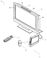
図1において、ゲームシステム1は、表示手段の一例の家庭用テレビジョン受像機(以下、モニタと記載する)2と、当該モニタ2に接続コードを介して接続する据置型のゲーム装置3とから構成される。モニタ2は、ゲーム装置3から出力された音声信号を音声出力するためのスピーカ2aを備える。また、ゲーム装置3は、本願発明のゲームプログラムの一例のゲームプログラムを記録した光ディスク4と、当該光ディスク4のゲームプログラムを実行してゲーム画面をモニタ2に表示出力させるためのコンピュータを搭載したゲーム装置本体5と、ゲーム画面に表示されたキャラクタ等を操作するゲームに必要な操作情報をゲーム装置本体5に与えるためのコントローラ7とを備えている。
In FIG. 1, a
また、ゲーム装置本体5は、無線コントローラモジュール19(図2参照)を内蔵する。無線コントローラモジュール19は、コントローラ7から無線送信されるデータを受信し、ゲーム装置本体5からコントローラ7へデータを送信して、コントローラ7とゲーム装置本体5とを無線通信によって接続する。さらに、ゲーム装置本体5には、当該ゲーム装置本体5に対して交換可能に用いられる情報記憶媒体の一例の光ディスク4が脱着される。
In addition, the
また、ゲーム装置本体5には、セーブデータ等のデータを固定的に記憶するバックアップメモリとして機能するフラッシュメモリ17(図2参照)が搭載される。ゲーム装置本体5は、光ディスク4に記憶されたゲームプログラム等を実行することによって、その結果をゲーム画像としてモニタ2に表示する。また、ゲームプログラム等は、光ディスク4に限らず、フラッシュメモリ17に予め記録されたものを実行するようにしてもよい。さらに、ゲーム装置本体5は、フラッシュメモリ17に記憶されたセーブデータを用いて、過去に実行されたゲーム状態を再現して、ゲーム画像をモニタ2に表示することもできる。そして、ゲーム装置3のプレイヤは、モニタ2に表示されたゲーム画像を見ながら、コントローラ7を操作することによって、ゲーム進行を楽しむことができる。
Further, the
コントローラ7は、無線コントローラモジュール19を内蔵するゲーム装置本体5へ、例えばBluetooth(ブルートゥース;登録商標)の技術を用いて操作情報等の送信データを無線送信する。コントローラ7は、主にモニタ2の表示画面に表示されるプレイヤオブジェクト等を操作するための操作手段である。コントローラ7は、片手で把持可能な程度の大きさのハウジングと、当該ハウジングの表面に露出して設けられた複数個の操作ボタン(十字キーやスティック等を含む)とが設けられている。また、後述により明らかとなるが、コントローラ7は、当該コントローラ7から見た画像を撮像する撮像情報演算部74を備えている。そして、撮像情報演算部74の撮像対象の一例として、モニタ2の表示画面近傍に2つのLEDモジュール(以下、マーカと記載する)8Lおよび8Rが設置される。これらマーカ8Lおよび8Rは、それぞれモニタ2の前方に向かって例えば赤外光を出力する。また、コントローラ7は、ゲーム装置本体5の無線コントローラモジュール19から無線送信された送信データを通信部75で受信して、当該送信データに応じた音や振動を発生させることもできる。
The
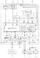
次に、図2を参照して、ゲーム装置本体5の内部構成について説明する。図2は、ゲーム装置本体5の構成を示すブロック図である。ゲーム装置本体5は、CPU(Central Processing Unit)10、システムLSI(Large Scale Integration)11、外部メインメモリ12、ROM/RTC(Read Only Memory/Real Time Clock)13、ディスクドライブ14、およびAV−IC(Audio Video−Integrated Circuit)15等を有する。
Next, the internal configuration of the
CPU10は、光ディスク4に記憶されたゲームプログラムを実行することによってゲーム処理を実行するものであり、ゲームプロセッサとして機能する。CPU10は、システムLSI11に接続される。システムLSI11には、CPU10の他、外部メインメモリ12、ROM/RTC13、ディスクドライブ14、およびAV−IC15が接続される。システムLSI11は、それに接続される各構成要素間のデータ転送の制御、表示すべき画像の生成、外部装置からのデータの取得等の処理を行う。なお、システムLSI11の内部構成については、後述する。揮発性の外部メインメモリ12は、光ディスク4から読み出されたゲームプログラムや、フラッシュメモリ17から読み出されたゲームプログラム等のプログラムを記憶したり、各種データを記憶したりするものであり、CPU10のワーク領域やバッファ領域として用いられる。ROM/RTC13は、ゲーム装置本体5の起動用のプログラムが組み込まれるROM(いわゆるブートROM)と、時間をカウントするクロック回路(RTC)とを有する。ディスクドライブ14は、光ディスク4からプログラムデータやテクスチャデータ等を読み出し、後述する内部メインメモリ35または外部メインメモリ12に読み出したデータを書き込む。
The
また、システムLSI11には、入出力プロセッサ31、GPU(Graphics Processor Unit)32、DSP(Digital Signal Processor)33、VRAM(Video RAM)34、および内部メインメモリ35が設けられる。図示は省略するが、これらの構成要素31〜35は、内部バスによって互いに接続される。
Further, the system LSI 11 is provided with an input /
GPU32は、描画手段の一部を形成し、CPU10からのグラフィクスコマンド(作画命令)に従って画像を生成する。VRAM34は、GPU32がグラフィクスコマンドを実行するために必要なデータ(ポリゴンデータやテクスチャデータ等のデータ)を記憶する。画像が生成される際には、GPU32は、VRAM34に記憶されたデータを用いて画像データを作成する。
The
DSP33は、オーディオプロセッサとして機能し、内部メインメモリ35や外部メインメモリ12に記憶されるサウンドデータや音波形(音色)データを用いて、音声データを生成する。
The
上述のように生成された画像データおよび音声データは、AV−IC15によって読み出される。AV−IC15は、AVコネクタ16を介して、読み出した画像データをモニタ2に出力するとともに、読み出した音声データをモニタ2に内蔵されるスピーカ2aに出力する。これによって、画像がモニタ2に表示されるとともに音がスピーカ2aから出力される。
The image data and audio data generated as described above are read out by the AV-
入出力プロセッサ(I/Oプロセッサ)31は、それに接続される構成要素との間でデータの送受信を実行したり、外部装置からのデータのダウンロードを実行したりする。入出力プロセッサ31は、フラッシュメモリ17、無線通信モジュール18、無線コントローラモジュール19、拡張コネクタ20、および外部メモリカード用コネクタ21に接続される。無線通信モジュール18にはアンテナ22が接続され、無線コントローラモジュール19にはアンテナ23が接続される。
The input / output processor (I / O processor) 31 transmits / receives data to / from components connected thereto and downloads data from an external device. The input /
入出力プロセッサ31は、無線通信モジュール18およびアンテナ22を介してネットワークに接続し、ネットワークに接続される他のゲーム装置や各種サーバと通信することができる。入出力プロセッサ31は、定期的にフラッシュメモリ17にアクセスし、ネットワークへ送信する必要があるデータの有無を検出し、当該データが有る場合には、無線通信モジュール18およびアンテナ22を介して当該データをネットワークに送信する。また、入出力プロセッサ31は、他のゲーム装置から送信されてくるデータやダウンロードサーバからダウンロードしたデータを、ネットワーク、アンテナ22、および無線通信モジュール18を介して受信し、受信したデータをフラッシュメモリ17に記憶する。CPU10は、ゲームプログラムを実行することにより、フラッシュメモリ17に記憶されたデータを読み出してゲームプログラムで利用する。フラッシュメモリ17には、ゲーム装置本体5と他のゲーム装置や各種サーバとの間で送受信されるデータの他、ゲーム装置本体5を利用してプレイしたゲームのセーブデータ(ゲームの結果データまたは途中データ)が記憶されてもよい。
The input /
また、入出力プロセッサ31は、アンテナ23および無線コントローラモジュール19を介して、コントローラ7から送信される操作データ等を受信し、内部メインメモリ35または外部メインメモリ12のバッファ領域に記憶(一時記憶)する。なお、内部メインメモリ35には、外部メインメモリ12と同様に、光ディスク4から読み出されたゲームプログラムや、フラッシュメモリ17から読み出されたゲームプログラム等のプログラムを記憶したり、各種データを記憶したりしてもよく、CPU10のワーク領域やバッファ領域として用いられてもかまわない。
The input /
さらに、入出力プロセッサ31には、拡張コネクタ20および外部メモリカード用コネクタ21が接続される。拡張コネクタ20は、USBやSCSIのようなインターフェースのためのコネクタであり、外部記憶媒体のようなメディアを接続したり、他のコントローラのような周辺機器を接続したり、有線の通信用コネクタを接続することによって無線通信モジュール18に替えてネットワークとの通信を行ったりすることができる。外部メモリカード用コネクタ21は、メモリカードのような外部記憶媒体を接続するためのコネクタである。例えば、入出力プロセッサ31は、拡張コネクタ20や外部メモリカード用コネクタ21を介して、外部記憶媒体にアクセスし、データを保存したり、データを読み出したりすることができる。
Furthermore, the
また、ゲーム装置本体5(例えば、前部主面)には、当該ゲーム装置本体5の電源ボタン24、ゲーム処理のリセットボタン25、光ディスク4を脱着する投入口、およびゲーム装置本体5の投入口から光ディスク4を取り出すイジェクトボタン26等が設けられている。電源ボタン24およびリセットボタン25は、システムLSI11に接続される。電源ボタン24がオンされると、ゲーム装置本体5の各構成要素に対して、図示しないACアダプタを介して電力が供給される。リセットボタン25が押されると、システムLSI11は、ゲーム装置本体5の起動プログラムを再起動する。イジェクトボタン26は、ディスクドライブ14に接続される。イジェクトボタン26が押されると、ディスクドライブ14から光ディスク4が排出される。
In addition, on the game apparatus main body 5 (for example, the front main surface), the power button 24 of the game apparatus
図3および図4を参照して、コントローラ7について説明する。なお、図3は、コントローラ7の上面後方から見た斜視図である。図4は、コントローラ7を下面前方から見た斜視図である。
The
図3および図4において、コントローラ7は、例えばプラスチック成型によって形成されたハウジング71を有しており、当該ハウジング71に複数の操作部72が設けられている。ハウジング71は、その前後方向を長手方向とした略直方体形状を有しており、全体として大人や子供の片手で把持可能な大きさである。
3 and 4, the
ハウジング71上面の中央前面側に、十字キー72aが設けられる。この十字キー72aは、十字型の4方向プッシュスイッチであり、4つの方向(前後左右)に対応する操作部分が十字の突出片にそれぞれ90°間隔で配置される。プレイヤが十字キー72aのいずれかの操作部分を押下することによって前後左右いずれかの方向を選択される。例えばプレイヤが十字キー72aを操作することによって、仮想ゲーム世界に登場するプレイヤキャラクタ等の移動方向を指示したり、複数の選択肢から選択指示したりすることができる。
A cross key 72 a is provided on the center front side of the upper surface of the
なお、十字キー72aは、上述したプレイヤの方向入力操作に応じて操作信号を出力する操作部であるが、他の態様の操作部でもかまわない。例えば、十字方向に4つのプッシュスイッチを配設し、プレイヤによって押下されたプッシュスイッチに応じて操作信号を出力する操作部を設けてもかまわない。さらに、上記4つのプッシュスイッチとは別に、上記十字方向が交わる位置にセンタスイッチを配設し、4つのプッシュスイッチとセンタスイッチとを複合した操作部を設けてもかまわない。また、ハウジング71上面から突出した傾倒可能なスティック(いわゆる、ジョイスティック)を倒すことによって、傾倒方向に応じて操作信号を出力する操作部を十字キー72aの代わりに設けてもかまわない。さらに、水平移動可能な円盤状部材をスライドさせることによって、当該スライド方向に応じた操作信号を出力する操作部を、上記十字キー72aの代わりに設けてもかまわない。また、タッチパッドを、十字キー72aの代わりに設けてもかまわない。
Note that the cross key 72a is an operation unit that outputs an operation signal in response to the above-described direction input operation of the player, but may be an operation unit of another mode. For example, four push switches may be provided in the cross direction, and an operation unit that outputs an operation signal according to the push switch pressed by the player may be provided. Further, apart from the four push switches, a center switch may be provided at a position where the cross direction intersects, and an operation unit in which the four push switches and the center switch are combined may be provided. An operation unit that outputs an operation signal in accordance with the tilt direction by tilting a tiltable stick (so-called joystick) protruding from the upper surface of the
ハウジング71上面の十字キー72aより後面側に、複数の操作ボタン72b〜72gが設けられる。操作ボタン72b〜72gは、プレイヤがボタン頭部を押下することによって、それぞれの操作ボタン72b〜72gに割り当てられた操作信号を出力する操作部である。例えば、操作ボタン72b〜72dには、1番ボタン、2番ボタン、およびAボタン等としての機能が割り当てられる。また、操作ボタン72e〜72gには、マイナスボタン、ホームボタン、およびプラスボタン等としての機能が割り当てられる。これら操作ボタン72a〜72gは、ゲーム装置本体5が実行するゲームプログラムに応じてそれぞれの操作機能が割り当てられる。なお、図3に示した配置例では、操作ボタン72b〜72dは、ハウジング71上面の中央前後方向に沿って並設されている。また、操作ボタン72e〜72gは、ハウジング71上面の左右方向に沿って操作ボタン72bおよび72dの間に並設されている。そして、操作ボタン72fは、その上面がハウジング71の上面に埋没しており、プレイヤが不意に誤って押下することのないタイプのボタンである。
A plurality of
また、ハウジング71上面の十字キー72aより前面側に、操作ボタン72hが設けられる。操作ボタン72hは、遠隔からゲーム装置本体5の電源をオン/オフする電源スイッチである。この操作ボタン72hも、その上面がハウジング71の上面に埋没しており、プレイヤが不意に誤って押下することのないタイプのボタンである。
An
また、ハウジング71上面の操作ボタン72cより後面側に、複数のLED702が設けられる。ここで、コントローラ7は、他のコントローラ7と区別するためにコントローラ種別(番号)が設けられている。例えば、LED702は、コントローラ7に現在設定されている上記コントローラ種別をプレイヤに通知するために用いられる。具体的には、無線コントローラモジュール19からコントローラ7へ、複数のLED702のうち、上記コントローラ種別に対応するLEDを点灯させるための信号が送信される。
A plurality of
また、ハウジング71上面には、操作ボタン72bおよび操作ボタン72e〜72gの間に後述するスピーカ(図5に示すスピーカ706)からの音を外部に放出するための音抜き孔が形成されている。
Further, on the upper surface of the
一方、ハウジング71下面には、凹部が形成されている。ハウジング71下面の凹部は、プレイヤがコントローラ7の前面をマーカ8Lおよび8Rに向けて片手で把持したときに、当該プレイヤの人差し指や中指が位置するような位置に形成される。そして、上記凹部の傾斜面には、操作ボタン72iが設けられる。操作ボタン72iは、例えばBボタンとして機能する操作部である。
On the other hand, a recess is formed on the lower surface of the
また、ハウジング71前面には、撮像情報演算部74の一部を構成する撮像素子743が設けられる。ここで、撮像情報演算部74は、コントローラ7が撮像した画像データを解析してその中で輝度が高い場所を判別してその場所の重心位置やサイズなどを検出するためのシステムであり、例えば、最大200フレーム/秒程度のサンプリング周期であるため比較的高速なコントローラ7の動きでも追跡して解析することができる。この撮像情報演算部74の詳細な構成については、後述する。また、ハウジング71の後面には、コネクタ73が設けられている。コネクタ73は、例えばエッジコネクタであり、例えば接続ケーブルと嵌合して接続するために利用される。
An
ここで、以下の説明を具体的にするために、コントローラ7に対して設定する座標系について定義する。図3および図4に示すように、互いに直交するXYZ軸をコントローラ7に対して定義する。具体的には、コントローラ7の前後方向となるハウジング71の長手方向をZ軸とし、コントローラ7の前面(撮像情報演算部74が設けられている面)方向をZ軸正方向とする。また、コントローラ7の上下方向をY軸とし、ハウジング71の上面(操作ボタン72aが設けられた面)方向をY軸正方向とする。さらに、コントローラ7の左右方向をX軸とし、ハウジング71の右側面(図3では表されている側面)方向をX軸正方向とする。
Here, in order to make the following description concrete, a coordinate system set for the
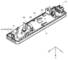
次に、図5および図6を参照して、コントローラ7の内部構造について説明する。なお、図5は、コントローラ7の上筐体(ハウジング71の一部)を外した状態を後面側から見た斜視図である。図6は、コントローラ7の下筐体(ハウジング71の一部)を外した状態を前面側から見た斜視図である。ここで、図6に示す基板700は、図5に示す基板700の裏面から見た斜視図となっている。
Next, the internal structure of the
図5において、ハウジング71の内部には基板700が固設されており、当該基板700の上主面上に操作ボタン72a〜72h、加速度センサ701、LED702、およびアンテナ754等が設けられる。そして、これらは、基板700等に形成された配線(図示せず)によってマイコン751等(図6、図7参照)に接続される。また、無線モジュール753(図7参照)およびアンテナ754によって、コントローラ7がワイヤレスコントローラとして機能する。なお、ハウジング71内部には図示しない水晶振動子が設けられており、後述するマイコン751の基本クロックを生成する。また、基板700の上主面上に、スピーカ706およびアンプ708が設けられる。また、加速度センサ701は、操作ボタン72dの左側の基板700上(つまり、基板700の中央部ではなく周辺部)に設けられる。したがって、加速度センサ701は、コントローラ7の長手方向を軸とした回転に応じて、重力加速度の方向変化に加え、遠心力による成分が含まれる加速度を検出することができるので、所定の演算により、検出される加速度データからコントローラ7の動きを良好な感度でゲーム装置本体5等が判定することができる。
In FIG. 5, a
一方、図6において、基板700の下主面上の前端縁に撮像情報演算部74が設けられる。撮像情報演算部74は、コントローラ7の前方から順に赤外線フィルタ741、レンズ742、撮像素子743、および画像処理回路744によって構成されており、それぞれ基板700の下主面に取り付けられる。また、基板700の下主面上の後端縁にコネクタ73が取り付けられる。さらに、基板700の下主面上にサウンドIC707およびマイコン751が設けられている。サウンドIC707は、基板700等に形成された配線によってマイコン751およびアンプ708と接続され、ゲーム装置本体5から送信されたサウンドデータに応じてアンプ708を介してスピーカ706に音声信号を出力する。
On the other hand, in FIG. 6, an imaging
そして、基板700の下主面上には、バイブレータ704が取り付けられる。バイブレータ704は、例えば振動モータやソレノイドである。バイブレータ704は、基板700等に形成された配線によってマイコン751と接続され、ゲーム装置本体5から送信された振動データに応じてその作動をオン/オフする。バイブレータ704が作動することによってコントローラ7に振動が発生するので、それを把持しているプレイヤの手にその振動が伝達され、いわゆる振動対応ゲームが実現できる。ここで、バイブレータ704は、ハウジング71のやや前方寄りに配置されるため、プレイヤが把持している状態において、ハウジング71が大きく振動することになり、振動を感じやすくなる。
A
次に、図7を参照して、コントローラ7の内部構成について説明する。なお、図7は、コントローラ7の構成を示すブロック図である。
Next, the internal configuration of the
図7において、コントローラ7は、上述した操作部72、撮像情報演算部74、加速度センサ701、バイブレータ704、スピーカ706、サウンドIC707、およびアンプ708の他に、その内部に通信部75を備えている。
In FIG. 7, the
撮像情報演算部74は、赤外線フィルタ741、レンズ742、撮像素子743、および画像処理回路744を含んでいる。赤外線フィルタ741は、コントローラ7の前方から入射する光から赤外線のみを通過させる。レンズ742は、赤外線フィルタ741を透過した赤外線を集光して撮像素子743へ出射する。撮像素子743は、例えばCMOSセンサやあるいはCCDのような固体撮像素子であり、レンズ742が集光した赤外線を撮像する。したがって、撮像素子743は、赤外線フィルタ741を通過した赤外線だけを撮像して画像データを生成する。撮像素子743で生成された画像データは、画像処理回路744で処理される。具体的には、画像処理回路744は、撮像素子743から得られた画像データを処理して高輝度部分を検知し、それらの位置座標や面積を検出した結果を示す処理結果データを通信部75へ出力する。なお、これらの撮像情報演算部74は、コントローラ7のハウジング71に固設されており、ハウジング71自体の方向を変えることによってその撮像方向を変更することができる。
The imaging
コントローラ7は、3軸(X、Y、Z軸)の加速度センサ701を備えていることが好ましい。この3軸の加速度センサ701は、3方向、すなわち、上下方向(図3に示すY軸)、左右方向(図3に示すX軸)、および前後方向(図3に示すZ軸)で直線加速度を検知する。また、少なくとも2軸方向(例えば、X軸、Y軸)に沿った直線加速度をそれぞれ検知する加速度検出手段を使用してもよい。例えば、これらの加速度センサ701は、アナログ・デバイセズ株式会社(Analog Devices, Inc.)またはSTマイクロエレクトロニクス社(STMicroelectronics N.V.)から入手可能であるタイプのものでもよい。加速度センサ701は、シリコン微細加工されたMEMS(Micro Electro Mechanical Systems:微小電子機械システム)の技術に基づいた静電容量式(静電容量結合式)であることが好ましい。しかしながら、既存の加速度検出手段の技術(例えば、圧電方式や圧電抵抗方式)あるいは将来開発される他の適切な技術を用いて、加速度センサ701が提供されてもよい。
The
加速度センサ701に用いられるような加速度検出手段は、加速度センサ701の持つ各軸に対応する直線に沿った加速度(直線加速度)のみを検知することができる。つまり、加速度センサ701からの直接の出力は、それら3軸のそれぞれに沿った直線加速度(静的または動的)を示す信号である。このため、加速度センサ701は、非直線状(例えば、円弧状)の経路に沿った動き、回転、回転運動、角変位、傾斜、位置、または姿勢等の物理特性を直接検知することはできない。
The acceleration detecting means used in the
しかしながら、加速度センサ701から出力される加速度の信号に基づいて、ゲーム装置のプロセッサ(例えばCPU10)またはコントローラのプロセッサ(例えばマイコン751)等のコンピュータが処理を行うことによって、コントローラ7に関するさらなる情報を推測または算出(判定)することができることは、当業者であれば本明細書の説明から容易に理解できるであろう。
However, based on the acceleration signal output from the
例えば、加速度センサ701を搭載するコントローラ7が静的な状態であることを前提としてコンピュータ側で処理する場合(すなわち、加速度センサ701によって検出される加速度が重力加速度のみであるとして処理する場合)、コントローラ7が現実に静的な状態であれば、検出された加速度に基づいてコントローラ7の姿勢が重力方向に対して傾いているか否か、またはどの程度傾いているかを知ることができる。具体的には、加速度センサ701の検出軸が鉛直下方向を向いている状態を基準としたとき、当該検出軸方向に1G(重力加速度)が作用しているか否かだけでコントローラ7が鉛直下方向に対して傾いているか否かを知ることができる。また、上記検出軸方向に作用している加速度の大きさによって、コントローラ7が鉛直下方向に対してどの程度傾いているかも知ることができる。また、多軸方向の加速度を検出可能な加速度センサ701の場合には、さらに各軸に対して検出された加速度の信号に対して処理を施すことによって、重力方向に対してコントローラ7がどの程度傾いているかをより詳細に知ることができる。この場合において、加速度センサ701からの出力に基づいて、プロセッサがコントローラ7の傾き角度のデータを算出する処理を行ってもよいが、当該傾き角度のデータを算出する処理を行うことなく、加速度センサ701からの出力に基づいて、おおよそのコントローラ7の傾き具合を推定するような処理としてもよい。このように、加速度センサ701をプロセッサと組み合わせて用いることによって、コントローラ7の傾き、姿勢、または位置を判定することができる。
For example, when processing is performed on the computer side on the assumption that the
一方、加速度センサ701が動的な状態であることを前提とする場合には、当該加速度センサ701が重力加速度成分に加えて加速度センサ701の動きに応じた加速度を検出するので、重力加速度成分を所定の処理により除去すれば、コントローラ7の動き方向等を知ることができる。具体的には、加速度センサ701を備えるコントローラ7がプレイヤの手で動的に加速されて動かされる場合に、加速度センサ701によって生成される加速度信号を処理することによって、コントローラ7の様々な動きおよび/または位置を算出することができる。なお、加速度センサ701が動的な状態であることを前提とする場合であっても、加速度センサ701の動きに応じた加速度を所定の処理により除去すれば、重力方向に対するコントローラ7の傾きを知ることが可能である。
On the other hand, when it is assumed that the
他の実施例では、加速度センサ701は、信号をマイコン751に出力する前に内蔵の加速度検出手段から出力される加速度信号に対して所望の処理を行うための、組込み式の信号処理装置または他の種類の専用の処理装置を備えていてもよい。例えば、組込み式または専用の処理装置は、加速度センサ701が静的な加速度(例えば、重力加速度)を検出するためのものである場合、検知された加速度信号をそれに相当する傾斜角(あるいは、他の好ましいパラメータ)に変換するものであってもよい。加速度センサ701でそれぞれ検知された加速度を示すデータは、通信部75に出力される。
In another embodiment, the
また、他の実施例では、加速度センサ701の代わりに、少なくとも一方を回転素子または振動素子などを内蔵したジャイロセンサを用いてもよい。この実施形態で使用されるMEMSジャイロセンサの一例として、アナログ・デバイセズ株式会社から入手可能なものがある。加速度センサ701と異なり、ジャイロセンサは、それが内蔵する少なくとも1つのジャイロ素子の軸を中心とした回転(または角速度)を直接検知することができる。このように、ジャイロセンサと加速度センサとは基本的に異なるので、個々の用途のためにいずれの装置が選択されるかによって、これらの装置からの出力信号に対して行う処理を適宜変更する必要がある。
In another embodiment, instead of the
具体的には、加速度センサの代わりにジャイロセンサを用いて傾きや姿勢を算出する場合には、大幅な変更を行う。すなわち、ジャイロセンサを用いる場合、検出開始の状態において傾きの値を初期化する。そして、当該ジャイロセンサから出力される角速度データを積分する。次に、初期化された傾きの値からの傾きの変化量を算出する。この場合、算出される傾きは、角度に対応する値が算出されることになる。一方、加速度センサによって傾きを算出する場合には、重力加速度のそれぞれの軸に関する成分の値を、所定の基準と比較することによって傾きを算出するので、算出される傾きはベクトルで表すことが可能であり、初期化を行わずとも、加速度検出手段を用いて検出される絶対的な方向を検出することが可能である。また、傾きとして算出される値の性質は、ジャイロセンサが用いられる場合には角度であるのに対して、加速度センサが用いられる場合にはベクトルであるという違いがある。したがって、加速度センサに代えてジャイロセンサが用いられる場合、当該傾きのデータに対して、2つのデバイスの違いを考慮した所定の変換を行う必要がある。加速度検出手段とジャイロスコープとの基本的な差異と同様にジャイロスコープの特性は当業者に公知であるので、本明細書ではさらなる詳細を省略する。ジャイロセンサは、回転を直接検知できることによる利点を有する一方、一般的には、加速度センサは、本実施形態で用いるようなコントローラに適用される場合、ジャイロセンサに比べて費用効率が良いという利点を有する。 Specifically, when the inclination or posture is calculated using a gyro sensor instead of the acceleration sensor, a significant change is made. That is, when the gyro sensor is used, the inclination value is initialized in the detection start state. Then, the angular velocity data output from the gyro sensor is integrated. Next, a change amount of the inclination from the initialized inclination value is calculated. In this case, the calculated inclination is a value corresponding to the angle. On the other hand, when the inclination is calculated by the acceleration sensor, the inclination is calculated by comparing the value of the component relating to each axis of the gravitational acceleration with a predetermined reference, so the calculated inclination can be expressed by a vector. Thus, it is possible to detect the absolute direction detected using the acceleration detecting means without performing initialization. In addition, the property of the value calculated as the inclination is an angle when a gyro sensor is used, but a vector when an acceleration sensor is used. Therefore, when a gyro sensor is used instead of the acceleration sensor, it is necessary to perform predetermined conversion in consideration of the difference between the two devices with respect to the tilt data. Since the characteristics of the gyroscope as well as the basic differences between the acceleration detection means and the gyroscope are known to those skilled in the art, further details are omitted here. While the gyro sensor has the advantage of being able to directly detect rotation, in general, the acceleration sensor has the advantage of being more cost effective than the gyro sensor when applied to a controller as used in this embodiment. Have.
通信部75は、マイクロコンピュータ(Micro Computer:マイコン)751、メモリ752、無線モジュール753、およびアンテナ754を含んでいる。マイコン751は、処理の際にメモリ752を記憶領域として用いながら、送信データを無線送信する無線モジュール753を制御する。また、マイコン751は、アンテナ754を介して無線モジュール753が受信したゲーム装置本体5からのデータに応じて、サウンドIC707およびバイブレータ704の動作を制御する。サウンドIC707は、通信部75を介してゲーム装置本体5から送信されたサウンドデータ等を処理する。また、マイコン751は、通信部75を介してゲーム装置本体5から送信された振動データ(例えば、バイブレータ704をONまたはOFFする信号)等に応じて、バイブレータ704を作動させる。
The
コントローラ7に設けられた操作部72からの操作信号(キーデータ)、加速度センサ701からの3軸方向の加速度信号(X、Y、およびZ軸方向加速度データ)、および撮像情報演算部74からの処理結果データは、マイコン751に出力される。マイコン751は、入力した各データ(キーデータ、X、Y、およびZ軸方向加速度データ、処理結果データ)を無線コントローラモジュール19へ送信する送信データとして一時的にメモリ752に格納する。ここで、通信部75から無線コントローラモジュール19への無線送信は、所定の周期毎に行われるが、ゲームの処理は1/60秒を単位として行われることが一般的であるので、それよりも短い周期で送信を行うことが必要となる。具体的には、ゲームの処理単位は16.7ms(1/60秒)であり、ブルートゥース(登録商標)で構成される通信部75の送信間隔は5msである。マイコン751は、無線コントローラモジュール19への送信タイミングが到来すると、メモリ752に格納されている送信データを一連の操作情報として出力し、無線モジュール753へ出力する。そして、無線モジュール753は、例えばブルートゥース(登録商標)の技術を用いて、操作情報を示す電波信号を所定周波数の搬送波を用いてアンテナ754から放射する。つまり、コントローラ7に設けられた操作部72からのキーデータ、加速度センサ701からのX、Y、およびZ軸方向加速度データ、および撮像情報演算部74からの処理結果データがコントローラ7から送信される。そして、ゲーム装置本体5の無線コントローラモジュール19でその電波信号を受信し、ゲーム装置本体5で当該電波信号を復調や復号することによって、一連の操作情報(キーデータ、X、Y、およびZ軸方向加速度データ、および処理結果データ)を取得する。そして、ゲーム装置本体5のCPU10は、取得した操作情報とゲームプログラムとに基づいて、ゲーム処理を行う。なお、ブルートゥース(登録商標)の技術を用いて通信部75を構成する場合、通信部75は、他のデバイスから無線送信された送信データを受信する機能も備えることができる。
An operation signal (key data) from the
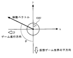
次に、ゲーム装置本体5が行う具体的な処理を説明する前に、図8〜図10を用いて本ゲーム装置本体5で行うゲームの概要について説明する。なお、図8は、モニタ2に表示されるゲーム画像の一例を示す図である。図9は、コントローラ7が振り動かされた際に、当該振り動作に応じてプレイヤオブジェクトOBJが移動する一例を示す図である。図10Aおよび図10Bは、コントローラ7の振り動作に応じて設定された移動方向が補正される一例を示す図である。
Next, before describing specific processing performed by the
図8において、モニタ2にはプレイヤオブジェクトOBJが仮想ゲーム世界を移動する様子が表示される。図8に示した一例では、プレイヤオブジェクトOBJが2次元の仮想ゲーム世界を左方向に進む(ゲーム進行方向)ゲームを示している。例えば、モニタ2に表示される仮想ゲーム世界は、所定のスピードで左スクロールし、プレイヤオブジェクトOBJがモニタ2に表示される仮想ゲーム世界内を移動する。つまり、仮想ゲーム世界内で仮想カメラが左方向に移動し、画面に表示される仮想ゲーム世界は右方向へ移動するので、ゲームは左に向かって進行することになる。そして、プレイヤは、プレイヤオブジェクトOBJを、仮想ゲーム世界に登場するターゲットTGと衝突させることによって所定の点数を得ることができる。
In FIG. 8, the
図9において、プレイヤオブジェクトOBJは、コントローラ7の振り方向に応じて仮想ゲーム世界内を移動する。図9では、実空間における右から左へコントローラ7が振られることに応じて、モニタ2に向かって仮想ゲーム世界の右から左へプレイヤオブジェクトOBJが移動する様子を示している。例えば、プレイヤがコントローラ7を振ることによって生じる加速度が加速度センサ701で検出され、当該加速度を示すデータがゲーム装置本体5へ送信される。そして、ゲーム装置本体5では、受信した加速度データに基づいて、コントローラ7が振られた方向を算出し、算出された振り方向に応じてプレイヤオブジェクトOBJの移動方向を設定する。この移動方向の設定において、ゲーム装置本体5では、プレイヤオブジェクトOBJがターゲットTGに当たりやすいように移動方向を補正する。以下、プレイヤオブジェクトOBJの移動方向を補正する対象となるターゲットTGを、補正ターゲットTGと称することがある。
In FIG. 9, the player object OBJ moves in the virtual game world according to the swing direction of the
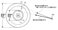
図10Aおよび図10Bにおいて、補正ターゲットTGには、誘導元範囲と誘導先範囲とが設定されている。誘導元範囲は、コントローラ7の振り方向に応じて仮想ゲーム世界に設定されたプレイヤオブジェクトOBJの移動方向を、補正対象とするか否かを判断する。設定された移動方向が現時点のプレイヤオブジェクトOBJの位置から誘導元範囲内を示す場合、当該誘導元範囲を設定している補正ターゲットTGに当該移動方向を近づけるように補正する。例えば、誘導元範囲は、プレイヤオブジェクトOBJと補正ターゲットTGとを結ぶ方向に対して垂直な方向(直線L)に沿って、補正ターゲットTGを中心とした範囲長さRoに設定される。
10A and 10B, a guidance source range and a guidance destination range are set for the correction target TG. The guidance source range determines whether or not the moving direction of the player object OBJ set in the virtual game world is to be corrected according to the swing direction of the
誘導先範囲は、プレイヤオブジェクトOBJの移動方向を補正ターゲットTGに近づける割合を設定する。例えば、補正対象となった移動方向は、誘導先範囲/誘導元範囲の割合で補正ターゲットTGに近づくように補正される。 The guidance destination range sets a rate at which the moving direction of the player object OBJ approaches the correction target TG. For example, the movement direction to be corrected is corrected so as to approach the correction target TG at the ratio of the guide destination range / guide source range.
具体的には、誘導先範囲は、プレイヤオブジェクトOBJと補正ターゲットTGとを結ぶ方向に対して垂直な方向(直線L)に沿って、補正ターゲットTGを中心とした範囲長さRt(Rt<Ro)に設定される。この場合、補正対象となった移動方向は、Rt/Roの割合で補正ターゲットTGに近づくように補正される。具体的には、補正前の移動方向と直線Lとの交点を点P0とし、点P0から補正ターゲットTGの中心までの距離をa(a<Ro/2)とする。この場合、距離aに応じて、直線Lに沿って補正ターゲットTGの中心から距離bとなる点P0側の点P1が設定される。ここで、距離bは、b=a*Rt/Roで算出される。そして、現時点のプレイヤオブジェクトOBJの位置から点P0に向かう補正前の移動方向は、現時点のプレイヤオブジェクトOBJの位置から点P1に向かう方向へ補正される。 Specifically, the guidance destination range is a range length Rt (Rt <Ro) centered on the correction target TG along a direction (straight line L) perpendicular to the direction connecting the player object OBJ and the correction target TG. ). In this case, the movement direction to be corrected is corrected so as to approach the correction target TG at a ratio of Rt / Ro. Specifically, the intersection point between the movement direction before correction and the straight line L is defined as a point P0, and the distance from the point P0 to the center of the correction target TG is defined as a (a <Ro / 2). In this case, a point P1 on the point P0 side that is a distance b from the center of the correction target TG along the straight line L is set according to the distance a. Here, the distance b is calculated by b = a * Rt / Ro. Then, the moving direction before correction from the current position of the player object OBJ toward the point P0 is corrected to a direction from the current position of the player object OBJ toward the point P1.
上述した移動方向の補正例から明らかなように、誘導先範囲のサイズ(範囲長さRt)を補正ターゲットTGのサイズより大きく設定することによって、補正後の移動方向が必ず補正ターゲットTGと交差するとは限らず、結果的にプレイヤオブジェクトOBJが補正ターゲットTGと衝突しないこともあり得る。つまり、移動方向が誘導元範囲内となった場合、当該移動方向が補正ターゲットTGに近づくように補正されるが、プレイヤオブジェクトOBJと補正ターゲットTGとが衝突するか否かについては当該移動方向が補正ターゲットTGにある程度近づいている場合に限られる。そのため、補正が行われても必ず補正ターゲットTGに命中するわけではないので、ゲームが不自然に簡単になり過ぎることを抑えることができる。また、誘導元範囲は、移動方向を補正対象とするか否かを判断するものとなる。したがって、誘導先範囲(範囲長さRt)のサイズおよび/または誘導元範囲のサイズ(範囲長さRo)を変更することによって、様々なゲームの難易度を調整することが可能である。難易度を低くしたい場合には、誘導先範囲の幅を補正ターゲットTGと同じにすれば、移動方向が誘導元範囲に向かっている場合には、補正によって必ずプレイヤオブジェクトOBJが補正ターゲットTGに命中することになる。 As is clear from the above-described correction example of the moving direction, if the size of the guide destination range (range length Rt) is set larger than the size of the correction target TG, the corrected moving direction always intersects the correction target TG. The player object OBJ may not collide with the correction target TG as a result. That is, when the moving direction falls within the guidance source range, the moving direction is corrected so as to approach the correction target TG, but whether or not the player object OBJ and the correction target TG collide is determined by the moving direction. This is limited to the case where the correction target TG is approached to some extent. Therefore, even if correction is performed, the correction target TG is not necessarily hit, so that it is possible to prevent the game from becoming unnaturally easy. In addition, the guidance source range determines whether or not the moving direction is a correction target. Therefore, it is possible to adjust the difficulty level of various games by changing the size of the guidance destination range (range length Rt) and / or the size of the guidance source range (range length Ro). If it is desired to lower the difficulty level, the width of the guidance destination range is made the same as that of the correction target TG. If the movement direction is toward the guidance source range, the player object OBJ always hits the correction target TG by the correction. Will do.
次に、ゲームシステム1において行われるゲーム処理の詳細を説明する。まず、図11を参照して、ゲーム処理において用いられる主なデータについて説明する。なお、図11は、ゲーム装置本体5の外部メインメモリ12および/または内部メインメモリ35(以下、2つのメインメモリを総称して、単にメインメモリと記載する)に記憶される主なデータおよびプログラムを示す図である。
Next, the details of the game process performed in the
図11に示すように、メインメモリのデータ記憶領域には、加速度データDa、加速度ベクトルデータDb、重力ベクトルデータDc、差分ベクトルデータDd、移動ベクトルデータDe、補正ターゲットデータDf、プレイヤオブジェクト位置データDg、および画像データDh等が記憶される。なお、メインメモリには、図11に示す情報に含まれるデータの他、ゲームに登場するプレイヤオブジェクトOBJ以外の他のオブジェクト等に関するデータ(位置データ等)や仮想ゲーム世界に関するデータ(背景のデータ等)等、ゲーム処理に必要なデータが記憶される。また、メインメモリのプログラム記憶領域には、ゲームプログラムを構成する各種プログラム群Paが記憶される。 As shown in FIG. 11, the data storage area of the main memory includes acceleration data Da, acceleration vector data Db, gravity vector data Dc, difference vector data Dd, movement vector data De, correction target data Df, player object position data Dg. , And image data Dh and the like are stored. In addition to the data included in the information shown in FIG. 11, the main memory stores data (position data, etc.) related to objects other than the player object OBJ that appears in the game, data related to the virtual game world (background data, etc. And the like, data necessary for game processing is stored. Various program groups Pa constituting the game program are stored in the program storage area of the main memory.
加速度データDaは、コントローラ7に生じた加速度を示すデータであり、コントローラ7から送信データとして送信されてくる一連の操作情報に含まれる加速度データが格納される。この加速度データDaには、加速度センサ701がX軸成分に対して検出した加速度を示すX軸方向加速度データDa1、Y軸成分に対して検出した加速度を示すY軸方向加速度データDa2、およびZ軸成分に対して検出した加速度を示すZ軸方向加速度データDa3が含まれる。なお、ゲーム装置本体5に備える無線コントローラモジュール19は、コントローラ7から所定周期(例えば、1/200秒毎)に送信される操作情報に含まれる加速度データを受信し、無線コントローラモジュール19に備える図示しないバッファに蓄えられる。その後、上記バッファに蓄えられた加速度データがゲーム処理周期である1フレーム毎(例えば、1/60秒毎)に読み出されて、メインメモリの加速度データDaが更新される。
The acceleration data Da is data indicating the acceleration generated in the
このとき、操作情報を受信する周期と処理周期とが異なるために、上記バッファには複数の時点に受信した操作情報が記述されていることになる。後述する処理の説明においては、後述する各ステップにおいて、複数の時点に受信した操作情報のうち最新の操作情報のみを常に用いて処理して、次のステップに進める態様を用いる。 At this time, since the cycle for receiving the operation information is different from the processing cycle, the operation information received at a plurality of times is described in the buffer. In the description of the processing to be described later, a mode is used in which, in each step to be described later, only the latest operation information among the operation information received at a plurality of points in time is always used for processing and the processing proceeds to the next step.
また、後述する処理フローでは、加速度データDaがゲーム処理周期である1フレーム毎に更新される例を用いて説明するが、他の処理周期で更新されてもかまわない。例えば、コントローラ7からの送信周期毎に加速度データDaを更新し、当該更新された加速度データDaをゲーム処理周期毎に利用する態様でもかまわない。この場合、加速度データDaに記憶する加速度データDa1〜Da3を更新する周期と、ゲーム処理周期とが異なることになる。
Further, in the processing flow to be described later, the acceleration data Da will be described using an example in which the frame is updated every game frame, but may be updated in other processing cycles. For example, the acceleration data Da may be updated every transmission cycle from the
加速度ベクトルデータDbは、X軸方向加速度データDa1、Y軸方向加速度データDa2、およびZ軸方向加速度データDa3が示す加速度を用いて算出される加速度ベクトルを示すデータであり、コントローラ7に作用している加速度の方向および大きさを示すデータが格納される。重力ベクトルデータDcは、コントローラ7に生じている重力の方向および大きさを表す重力ベクトルを示すデータが格納される。差分ベクトルデータDdは、上記加速度ベクトルから上記重力ベクトルを減算したベクトル(差分ベクトル)を示すデータが格納される。移動ベクトルデータDeは、上記差分ベクトルに応じて仮想ゲーム世界に設定されるプレイヤオブジェクトOBJの移動方向および移動速度を示すデータ(移動ベクトル)が格納される。
The acceleration vector data Db is data indicating an acceleration vector calculated using the acceleration indicated by the X-axis direction acceleration data Da1, the Y-axis direction acceleration data Da2, and the Z-axis direction acceleration data Da3. Data indicating the direction and magnitude of the acceleration is stored. The gravity vector data Dc stores data indicating a gravity vector indicating the direction and magnitude of gravity generated in the
補正ターゲットデータDfは、上述した補正ターゲットTG毎に、優先度データDf1、補正ターゲット位置データDf2、誘導元範囲データDf3、および誘導先範囲データDf4を含んでおり、補正ターゲットTG毎の各種情報を示すデータが格納される。優先度データDf1は、補正ターゲットTGをプレイヤオブジェクトOBJの移動方向を補正する補正対象とするか否かを判断するための優先度を示すデータである。補正ターゲット位置データDf2は、仮想ゲーム世界において補正ターゲットTGが配置される位置を示すデータである。誘導元範囲データDf3は、補正ターゲットTGに設定されている上記誘導元範囲を示すデータである。誘導先範囲データDf4は、補正ターゲットTGに設定されている上記誘導先範囲を示すデータである。 The correction target data Df includes priority data Df1, correction target position data Df2, guidance source range data Df3, and guidance destination range data Df4 for each correction target TG described above, and various information for each correction target TG. The data shown is stored. The priority data Df1 is data indicating priority for determining whether or not the correction target TG is a correction target for correcting the moving direction of the player object OBJ. The correction target position data Df2 is data indicating a position where the correction target TG is arranged in the virtual game world. The guidance source range data Df3 is data indicating the guidance source range set in the correction target TG. The guidance destination range data Df4 is data indicating the guidance destination range set in the correction target TG.
プレイヤオブジェクト位置データDgは、仮想ゲーム世界においてプレイヤオブジェクトOBJが配置される位置を示すデータが格納される。 The player object position data Dg stores data indicating the position where the player object OBJ is arranged in the virtual game world.
画像データDhは、プレイヤオブジェクト画像データDh1、補正ターゲット画像データDh2、および背景画像データDh3等を含んでいる。プレイヤオブジェクト画像データDh1は、仮想ゲーム世界にプレイヤオブジェクトOBJを配置してゲーム画像を生成するためのデータである。補正ターゲット画像データDh2は、仮想ゲーム世界に補正ターゲットTGをそれぞれ配置してゲーム画像を生成するためのデータである。背景画像データDh3は、仮想ゲーム世界に背景を配置してゲーム画像を生成するためのデータである。 The image data Dh includes player object image data Dh1, correction target image data Dh2, background image data Dh3, and the like. The player object image data Dh1 is data for generating a game image by arranging the player object OBJ in the virtual game world. The corrected target image data Dh2 is data for generating a game image by arranging each corrected target TG in the virtual game world. The background image data Dh3 is data for generating a game image by arranging a background in the virtual game world.
次に、図12〜図14を参照して、ゲーム装置本体5において行われるゲーム処理の詳細を説明する。なお、図12は、ゲーム装置本体5において実行されるゲーム処理における前半の動作の一例を示すフローチャートである。図13は、ゲーム装置本体5において実行されるゲーム処理における後半の動作の一例を示すフローチャートである。図14は、図13におけるステップ53の移動方向補正処理の一例の詳細な動作を示すサブルーチンである。なお、図12〜図14に示すフローチャートにおいては、ゲーム処理のうち、プレイヤがコントローラ7を振ってプレイヤオブジェクトOBJが移動させる処理について主に説明し、本願発明と直接関連しない他のゲーム処理については詳細な説明を省略する。また、図12〜図14では、CPU10が実行する各ステップを「S」と略称する。
Next, with reference to FIG. 12 to FIG. 14, details of the game processing performed in the
ゲーム装置本体5の電源が投入されると、ゲーム装置本体5のCPU10は、ROM/RTC13に記憶されている起動用のプログラムを実行し、これによってメインメモリ等の各ユニットが初期化される。そして、光ディスク4に記憶されたゲームプログラムがメインメモリに読み込まれ、CPU10によって当該ゲームプログラムの実行が開始される。図12〜図14に示すフローチャートは、以上の処理が完了した後に行われるゲーム処理を示すフローチャートである。
When the power of the
図12において、CPU10は、ゲーム処理の初期化を行い(ステップ40)、次のステップに処理を進める。例えば、上記ステップ40におけるゲーム処理初期化では、仮想ゲーム世界の設定やプレイヤオブジェクトOBJ、補正ターゲットTG、および補正対象等はならない他のターゲットの配置等の初期設定を行う。また、上記ステップ40におけるゲーム処理初期化では、以降のゲーム処理で用いる各パラメータを初期化する。例えば、CPU10は、上述したメインメモリに格納される各データDa〜Deが示すパラメータをそれぞれ0に設定する。さらに、上記ステップ40におけるゲーム処理初期化では、モニタ2に表示される仮想ゲーム世界において、ゲーム進行方向(図8参照)を設定する。例えば、ゲーム進行方向は、モニタ2に向かって左方向、右方向、上方向、または下方向の何れか等に設定される。ここで、ゲーム進行方向が左方向に設定される場合、コントローラ7を左手で把持するプレイヤ(すなわち、左利きのプレイヤ)は、遊技が難しくなることがある。また、ゲーム進行方向が右方向に設定される場合、コントローラ7を右手で把持するプレイヤ(すなわち、右利きのプレイヤ)は、遊技が難しくなることがある。このような利き手による有利/不利を考慮するために、予め設定されたプレイヤの利き手に応じて、ゲーム進行方向を設定してもかまわない。
In FIG. 12, the
次に、CPU10は、コントローラ7が振られたと判定された後の経過時間が、所定時間に到達したか否かを判断する(ステップ41)。後述により明らかとなるが、CPU10は、ステップ47においてコントローラ7が振られたことを判定しており、当該ステップの処理からの経過時間を計時している。そして、CPU10は、上記経過時間が所定時間(例えば、0.3秒)に到達したか否かを判断する。CPU10は、上記経過時間が所定時間に到達した場合、処理を次のステップ42に進める。一方、CPU10は、上記経過時間が所定時間に到達していない場合、処理を次のステップ53(図13参照)に進める。
Next, the
なお、上記ステップ41の処理は、コントローラ7の振り判定後の誤判定を防止するために行われている。例えば、コントローラ7が振られていると判定した直後に生じている加速度は、コントローラ7を振る動作を止めるときに発生する逆方向の加速度や、プレイヤがコントローラ7を振る際のバックスイング(振りかぶり動作)直後に当該バックスイングの逆方向に振られるときに発生する加速度である可能性が高い。つまり、一連の振り動作において、真逆方向の加速度が生じることがあり、これらの加速度全てを振り判定に用いると現実にコントローラ7を振っている方向の判定が難しくなる。本実施形態では、コントローラ7が振られていると判定された後の一定時間(例えば、0.3秒)に生じる加速度を次の振り判定に用いないことによって、直前の振り判定で用いた加速度に対して真逆方向の加速度を用いた振り判定が次に行われることを防止している。
Note that the processing of
ステップ42において、CPU10は、コントローラ7から加速度を示すデータを取得して、次のステップに処理を進める。例えば、CPU10は、コントローラ7から受信した操作情報を取得し、当該操作情報に含まれる最新の加速度データが示す加速度を用いて加速度データDaに格納する。具体的には、CPU10は、コントローラ7から受信した最新の操作情報に含まれるX軸方向の加速度データが示す加速度を用いて、X軸方向加速度データDa1を更新する。また、CPU10は、最新の操作情報に含まれるY軸方向の加速度データが示す加速度を用いて、Y軸方向加速度データDa2を更新する。そして、CPU10は、最新の操作情報に含まれるZ軸方向の加速度データが示す加速度を用いて、Z軸方向加速度データDa3を更新する。
In
次に、CPU10は、加速度ベクトルを算出して当該加速度ベクトルの大きさが1G(≒9.8m/s2)に近い状態で一定時間継続しているか否かを判断する(ステップ43)。例えば、CPU10は、X軸方向加速度データDa1に格納されたX軸方向加速度、Y軸方向加速度データDa2に格納されたY軸方向加速度、およびZ軸方向加速度データDa3に格納されたZ軸加速度を用いて、それぞれの方向の加速度成分を有する加速度ベクトルを算出し、当該加速度ベクトルを用いて加速度ベクトルデータDbを更新する。そして、上記加速度ベクトルの大きさが1.0G近傍(例えば、1.0G±10%)となっている時間が所定時間(例えば、0.1秒)継続しているか否かを判断する。そして、CPU10は、加速度ベクトルの大きさが1Gに近い状態で一定時間継続している場合、次のステップ44に処理を進める。一方、CPU10は、加速度ベクトルの大きさが1Gに近い状態で一定時間継続していない場合、次のステップ45に処理を進める。
Next, the
ステップ44において、CPU10は、現時点の加速度ベクトルを重力ベクトルに設定し、次のステップ45に処理を進める。例えば、CPU10は、加速度ベクトルデータDbを参照して、加速度ベクトルデータDbが示す加速度ベクトルを用いて重力ベクトルデータDcを更新する。ここで、上記ステップ44は、上記加速度ベクトルの大きさが1.0G近傍となっている時間が所定時間継続している場合に実行される。つまり、コントローラ7に作用する加速度の大きさが1.0G近傍で安定している場合であり、すなわちコントローラ7が静的な状態にあると推定される。したがって、コントローラ7が静的な状態で作用している加速度が重力加速度であると推定されるため、上記状態で検出される加速度ベクトルは、コントローラ7に作用する重力加速度のベクトル(重力ベクトル)として取り扱うことができる。
In step 44, the
ステップ45において、CPU10は、加速度ベクトルから重力ベクトルを減算して差分ベクトルを算出し、次のステップに処理を進める。例えば、CPU10は、加速度ベクトルデータDbおよび重力ベクトルデータDcを参照して、加速度ベクトルデータDbが示す加速度ベクトルから重力ベクトルデータDcが示す重力ベクトルを減算して差分ベクトルを算出し、当該差分ベクトルを用いて差分ベクトルデータDdを更新する。
In
次に、CPU10は、差分ベクトルのZ軸成分を除外したXY軸成分の大きさが所定値以上か否かを判断する(ステップ46)。ここで、上記所定値は、プレイヤによってコントローラ7が振られたか否かを判定するための閾値であり、静的な状態でもコントローラ7に作用している重力加速度(すなわち、1.0G)より大きな値に設定される。なお、差分ベクトルのZ軸成分については、コントローラ7が振られた場合の遠心力によって他軸成分(XY軸成分)より過大となるので、本実施形態ではZ軸成分を除外してコントローラ7の振り判定を行っている。そして、CPU10は、差分ベクトルのXY軸成分の大きさが所定値以上の場合、次のステップ47に処理を進める。一方、CPU10は、差分ベクトルのXY軸成分の大きさが所定値未満の場合、次のステップ53(図13参照)に処理を進める。
Next, the
ステップ47において、CPU10は、コントローラ7が振られたと判定し、当該判定後の経過時間のカウントを開始する。そして、CPU10は、次のステップに処理を進める。
In
次に、CPU10は、現時点の差分ベクトルを仮想ゲーム世界における移動ベクトルに変換し(ステップ48)、次のステップに処理を進める。例えば、CPU10は、差分ベクトルデータDdを参照して、差分ベクトルデータDdが示す差分ベクトルを移動ベクトルに変換し、当該移動ベクトルを用いて移動ベクトルデータDeを更新する。以下、差分ベクトルを移動ベクトルに変換する一例を説明する。
Next, the
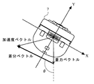
図15Aは、コントローラ7の底面から見た図を示している。図15Aに示すように、上記ステップ45において、加速度ベクトルから重力ベクトルを減算した差分ベクトルが算出されている。ここで、上述したように、重力ベクトルは、コントローラ7が静的な状態で作用している重力加速度の方向および大きさを示している。一方、加速度ベクトルは、コントローラ7自体が動く(例えば、振られる)ことによって生じる加速度に上記重力加速度が加わった状態で検出される。したがって、差分ベクトルは、コントローラ7自体が動くことによって生じる加速度の方向および大きさを示すデータとして取り扱うことができる。
FIG. 15A shows a view seen from the bottom surface of the
重力ベクトルの方向と差分ベクトルの方向とが成す角度は、重力加速度の方向を基準としてコントローラ7自体が動くことによって生じる加速度の方向を示すパラメータとして用いることができる。後述するゲーム例では、2次元の仮想ゲーム世界を取り扱うため、重力ベクトルのZ軸成分および差分ベクトルのZ軸成分をそれぞれ0として、重力ベクトルの方向と差分ベクトルの方向とが成す角度θを算出する。
The angle formed by the direction of the gravity vector and the direction of the difference vector can be used as a parameter indicating the direction of acceleration generated by the movement of the
一方、モニタ2には、例えば2次元の仮想ゲーム世界が表示されている。ここで、以下の説明を具体的にするために、仮想ゲーム世界に対して設定する座標系について定義する。図15Bに示すように、互いに直交するxy軸を2次元の仮想ゲーム世界に対して定義する。具体的には、仮想ゲーム世界における左右方向をx軸とし、モニタ2に向かって仮想ゲーム世界の右方向をx軸正方向とする。また、仮想ゲーム世界における上下方向をy軸とし、モニタ2に向かって仮想ゲーム世界の上方向をy軸正方向とする。
On the other hand, for example, a two-dimensional virtual game world is displayed on the
差分ベクトルを移動ベクトルに変換する際、差分ベクトルのX軸成分およびY軸成分を、それぞれ仮想ゲーム世界のx軸成分およびy軸成分に置換したベクトルを設定する。そして、仮想ゲーム世界における下方向(すなわち、y軸負方向)との間で成す角度が角度θとなるように上記ベクトルの方向を回転させて、仮想ゲーム世界における移動ベクトルを設定する。なお、移動ベクトルの大きさは、ゲームの操作環境や操作感度に応じて設定すればよく、例えば差分ベクトルの大きさに所定の割合を乗じた値に設定すればよい。 When the difference vector is converted into the movement vector, a vector is set in which the X-axis component and the Y-axis component of the difference vector are replaced with the x-axis component and the y-axis component of the virtual game world, respectively. Then, the direction of the vector is rotated so that the angle formed between the downward direction in the virtual game world (that is, the negative y-axis direction) is the angle θ, and the movement vector in the virtual game world is set. Note that the magnitude of the movement vector may be set according to the game operating environment and the operation sensitivity, for example, a value obtained by multiplying the magnitude of the difference vector by a predetermined ratio.
図12に戻り、CPU10は、上記ステップ48で算出された移動ベクトルの方向が、ゲーム進行方向に対して逆方向か否かを判断する(ステップ49)。一例として、図15Bに示したように、ゲーム進行方向がx軸負方向である場合、CPU10は、上記ステップ48で算出された移動ベクトルのx軸成分が正のときに当該移動ベクトルがゲーム進行方向に対して逆方向であると判断する。そして、CPU10は、移動ベクトルの方向が、ゲーム進行方向に対して逆方向である場合、次のステップ50に処理を進める。一方、CPU10は、移動ベクトルの方向が、ゲーム進行方向に対して順方向である場合、次のステップ51(図13参照)に処理を進める。
Returning to FIG. 12, the
ステップ50において、CPU10は、上記ステップ48で算出された移動ベクトルの方向を反転させて、次のステップ51に処理を進める。例えば、CPU10は、移動ベクトルデータDeを参照して、移動ベクトルデータDeが示す移動ベクトルのx軸成分およびy軸成分の正負をそれぞれ逆にすることによって当該移動ベクトルの方向を反転させ、反転させた移動ベクトルを用いて移動ベクトルデータDeを更新する。ここで、図8および図9に示したように、本実施形態は、ゲームコントローラ7の振り方向に応じてプレイヤオブジェクトOBJを仮想ゲーム世界内で移動させながら、仮想ゲーム世界のゲーム進行方向に進んでいくゲームを用いている。したがって、プレイヤがコントローラ7を仮想ゲーム世界のゲーム進行方向とは逆に振る操作がないため、ゲーム進行方向とは逆の移動ベクトルが得られた場合は、プレイヤがコントローラ7を振る際のバックスイング(振りかぶり動作)の可能性が高い。この場合、本実施形態では、当該バックスイング直後にコントローラ7が振られ、当該バックスイングが直後の振り方向とは真逆の方向であると仮定し、当該仮定に基づいて移動ベクトルの反転を行っている。したがって、別の実施形態において、プレイヤオブジェクトがいずれの方向にも移動可能である場合には、ステップ50の反転を行わないようにしてもよい。
In step 50, the
ステップ51(図13)において、CPU10は、プレイヤオブジェクトOBJが移動可能な状態であるか否かを判断する。例えば、ゲーム進行上の演出において、プレイヤオブジェクトOBJが停止状態となっている場合、CPU10は、プレイヤオブジェクトOBJが移動可能な状態にないと判断する。そして、CPU10は、プレイヤオブジェクトOBJが移動可能な状態である場合、次のステップ52に処理を進める。一方、CPU10は、プレイヤオブジェクトOBJが移動可能な状態にない場合、次のステップ53に処理を進める。
In step 51 (FIG. 13), the
ステップ52において、CPU10は、移動ベクトルの方向(移動方向)を補正する処理を行い、次のステップに処理を進める。以下、図14を参照して、上記ステップ52で行う移動方向補正処理の動作について説明する。
In
図14において、CPU10は、モニタ2に表示されている表示画面内に補正ターゲットTGがあるか否かを判断する(ステップ60)。そして、CPU10は、表示画面内に補正ターゲットTGがある場合、次のステップ61に処理を進める。一方、CPU10は、表示画面内に補正ターゲットTGがない場合、次のステップ69に処理を進める。
In FIG. 14, the
ステップ61において、CPU10は、表示画面内に表示されている補正ターゲットTGに対する処理順序を設定し、次のステップに処理を進める。例えば、CPU10は、表示画面内に表示されている補正ターゲットTG毎に優先度データDf1が示す優先度を抽出し、当該優先度に基づいて補正ターゲットTGの処理順序を設定する。ここで、補正ターゲットTGの優先度は、補正ターゲットTGの種別等に応じて設定される。例えば、ゲームのルール上、他のターゲットと比較して重要なターゲットについては、その優先度を高くして処理対象となりやすくする。また、逆に他のターゲットと比較して重要なターゲットについては、その優先度を低くして処理対象となりにくくしてもよい。
In step 61, the
なお、上記ステップ61における処理順序の設定においては、上記優先度を考慮しながら、補正ターゲット位置データDf2およびプレイヤオブジェクト位置データDgを参照して、プレイヤオブジェクトOBJとの距離に応じて処理順序を設定してもかまわない。一例として、上記優先度が同じ補正ターゲットTGについては、プレイヤオブジェクトOBJからの距離が相対的に短い補正ターゲットTGの処理順序を先に設定する。他の例として、プレイヤオブジェクトOBJからの距離が相対的に短い補正ターゲットTGの処理順序が優先されるように処理順序を設定し、当該距離が同じ補正ターゲットTGについては、上記優先度が高い補正ターゲットTGの処理順序を先に設定する。 In the setting of the processing order in step 61, the processing order is set according to the distance from the player object OBJ with reference to the correction target position data Df2 and the player object position data Dg while taking the priority into consideration. It doesn't matter. As an example, for the correction target TG having the same priority, the processing order of the correction target TG having a relatively short distance from the player object OBJ is set first. As another example, the processing order is set so that the processing order of the correction target TG having a relatively short distance from the player object OBJ is prioritized, and the correction target TG having the same distance has a high priority. The processing order of the target TG is set first.
次に、CPU10は、上記ステップ61で設定した処理順序の順に補正ターゲットTGを選択する(ステップ62)。そして、CPU10は、選択された補正ターゲットTGの補正ターゲット位置データDf2およびプレイヤオブジェクト位置データDgを参照して、上記ステップ62で選択された補正ターゲットTGがプレイヤオブジェクトOBJに対してゲーム進行方向側にあるか否かを判断する(ステップ63)。そして、CPU10は、補正ターゲットTGがプレイヤオブジェクトOBJに対してゲーム進行方向側にある場合、次のステップ64に処理を進める。一方、CPU10は、補正ターゲットTGがプレイヤオブジェクトOBJに対してゲーム進行方向側にない場合、次のステップ68に処理を進める。
Next, the
ステップ64において、選択された補正ターゲットTGに対する点P0を算出する。そして、CPU10は、点P0から補正ターゲットTGの中心までの距離aが、選択された補正ターゲットTGの誘導元範囲の範囲長さRoの半分の長さ(Ro/2)より短いか否かを判断する(ステップ65)。そして、CPU10は、a<Ro/2の場合、次のステップ66に処理を進める。一方、CPU10は、a≧Ro/2の場合、次のステップ68に処理を進める。
In step 64, a point P0 for the selected correction target TG is calculated. Then, the
図10Aを用いて説明したように、点P0は、プレイヤオブジェクトOBJと補正ターゲットTGとを結ぶ方向に対して垂直な方向(直線L)と移動ベクトルの方向(移動方向)との交点によって求められる。そして、点P0から補正ターゲットTGの中心までの距離aと誘導元範囲の範囲長さRoの半分とを比較することによって、設定されている移動方向が現時点のプレイヤオブジェクトOBJの位置から選択されている補正ターゲットTGの誘導元範囲内を示すか否か、すなわちから選択されている補正ターゲットTGを補正対象とするか否かを判定している。上記ステップ64およびステップ65においては、CPU10は、移動ベクトルデータDeとプレイヤオブジェクト位置データDgと選択されている補正ターゲットTGの補正ターゲット位置データDf2および誘導元範囲データDf3とを参照して、これらの判定を行う。
As described with reference to FIG. 10A, the point P0 is obtained by the intersection of the direction (straight line L) perpendicular to the direction connecting the player object OBJ and the correction target TG and the direction of the movement vector (movement direction). . Then, by comparing the distance a from the point P0 to the center of the correction target TG with half the range length Ro of the guidance source range, the set moving direction is selected from the current position of the player object OBJ. It is determined whether the correction target TG is within the guidance source range, that is, whether the correction target TG selected from the correction target TG is to be corrected. In step 64 and
ステップ66において、CPU10は、a<Ro/2の場合、すなわち選択された補正ターゲットTGが補正対象となる場合、当該補正ターゲットTGに対する点P1を算出する。そして、CPU10は、算出された点P1への方向となるように移動方向を補正し(ステップ67)、次のステップに処理を進める。
In step 66, if a <Ro / 2, that is, if the selected correction target TG is a correction target, the
図10Bを用いて説明したように、点P1は、直線Lに沿って補正ターゲットTGの中心から距離b(=a*Rt/Ro)となる点P0側に設定される。これによって、移動方向は、補正対象となった補正ターゲットTGに対してRt/Roの割合で近づくように補正される。上記ステップ66およびステップ67においては、CPU10は、プレイヤオブジェクト位置データDgと選択されている補正ターゲットTGの補正ターゲット位置データDf2、誘導元範囲データDf3、および誘導先範囲データDf4とを参照して、これらの算出を行う。そして、CPU10は、移動ベクトルデータDeを参照して、移動ベクトルデータDeが示す移動ベクトルの方向を補正された移動方向に変更し、変更後の移動ベクトルを用いて移動ベクトルデータDeを更新する。
As described with reference to FIG. 10B, the point P1 is set along the straight line L to the point P0 side at a distance b (= a * Rt / Ro) from the center of the correction target TG. Thus, the moving direction is corrected so as to approach the correction target TG that is the correction target at a ratio of Rt / Ro. In step 66 and step 67, the
一方、ステップ68において、CPU10は、上記ステップ61で処理順序が設定された補正ターゲットTGにおいて、未処理の補正ターゲットTGがあるか否かを判断する。そして、CPU10は、未処理の補正ターゲットTGがない場合、次のステップ69に処理を進める。一方、CPU10は、未処理の補正ターゲットTGがある場合、上記ステップ62に戻って処理を繰り返す。
On the other hand, in
ステップ69において、CPU10は、現時点の移動ベクトルデータDeが示す移動ベクトルを、以降のゲーム処理に用いる移動ベクトルとして決定し、当該サブルーチンによる処理を終了する。
In step 69, the
図13に戻り、上記ステップ52の移動方向補正処理の後、CPU10は、ゲーム処理を行い(ステップ53)、当該ゲーム処理に応じたゲーム画像をモニタ2に表示する表示処理を行って(ステップ54)、次のステップに処理を進める。例えば、ステップ53において、CPU10は、移動ベクトルデータDeが示す移動ベクトルに基づいて、仮想ゲーム世界におけるプレイヤオブジェクトOBJを移動させる。また、CPU10は、仮想ゲーム世界においてプレイヤオブジェクトOBJが他のオブジェクト等と接触した場合、当該オブジェクトに応じた処理(オブジェクトを破壊する、オブジェクトで反射する等)を行う。また、CPU10は、プレイヤオブジェクトOBJの移動とは関係しない他のゲーム処理等も行う。
Returning to FIG. 13, after the moving direction correction process in
なお、移動ベクトルデータDeが示す移動ベクトルは、上記ステップ53のゲーム処理の後、当該ゲーム処理内容に応じて変化させてもかまわない。例えば、上記ステップ53のゲーム処理の後、移動ベクトルを所定の割合で減衰させてもいいし、上記ゲーム処理によってプレイヤオブジェクトOBJが他のオブジェクトと接触した場合に移動ベクトルの方向を変化させてもかまわない。CPU10は、上記ステップ53のゲーム処理の後に移動ベクトルを変化させた場合、変化後の移動ベクトルを用いて移動ベクトルデータDeを更新する。
Note that the movement vector indicated by the movement vector data De may be changed according to the content of the game process after the game process of
次に、CPU10は、ゲームを終了するか否かを判断する(ステップ55)。ゲームを終了する条件としては、例えば、ゲームオーバーとなる条件が満たされたことや、プレイヤがゲームを終了する操作を行ったこと等がある。CPU10は、ゲームを終了しない場合に上記ステップ41(図12参照)に戻って処理を繰り返し、ゲームを終了する場合に当該フローチャートによる処理を終了する。
Next, the
このように、上述したゲーム処理によれば、コントローラ7の振り方向に応じて移動するプレイヤオブジェクトOBJが補正ターゲットTGに近づくように、プレイヤオブジェクトOBJの移動方向が補正される。したがって、仮想ゲーム世界内の補正ターゲットTGにプレイヤオブジェクトOBJを衝突させるような操作をプレイヤが望んでいる場合、プレイヤオブジェクトOBJから補正ターゲットTGへ向かう方向とコントローラ7の振り方向とが完全に一致していなくても、当該衝突を実現することができる。つまり、プレイヤは、プレイヤオブジェクトOBJから補正ターゲットTGへ向かう方向に、ある程度近づけた振り方向でコントローラ7を振ることによって所望の操作が可能となり、精密な操作が求められない。
Thus, according to the game process described above, the moving direction of the player object OBJ is corrected so that the player object OBJ moving according to the swing direction of the
一方、プレイヤがコントローラ7を振り動かせば必ず補正ターゲットTGと衝突するような設定にしてしまうと、ゲームが大味となって面白みがなくなってしまう。上述したゲーム処理では、補正ターゲットTGの誘導元範囲および誘導先範囲のサイズを調整することによって、移動方向の補正割合を調整している。つまり、プレイヤオブジェクトOBJから補正ターゲットTGへ向かう方向とコントローラ7の振り方向との差が大きい場合は、プレイヤオブジェクトOBJが補正ターゲットTGと衝突しないように調整することも可能である。この場合、プレイヤは、補正ターゲットTGにプレイヤオブジェクトOBJが衝突するようにある程度狙ってコントローラ7を振ることが必要となる。具体的には、補正ターゲットTGのサイズに対する誘導先範囲のサイズを調整することによって、上記補正割合が調整される。また、誘導元範囲のサイズを調整することによって、補正ターゲットTGが補正対象となる確率を調整することも可能である。このように、上述したゲーム処理では、誘導先範囲(範囲長さRt)のサイズおよび/または誘導元範囲のサイズ(範囲長さRo)を変更することによって、様々なゲームの難易度を調整することが可能である。
On the other hand, if the player always swings the
なお、補正ターゲットTGに設定される誘導元範囲および誘導先範囲は、他の形状で設定されてもかまわない。以下、図16Aおよび図16Bを用いて、他の形状で設定された誘導元範囲および誘導先範囲の一例について説明する。なお、図16Aおよび図16Bは、補正ターゲットTGに対して誘導元範囲および誘導先範囲が円形で設定された一例を示す図である。 Note that the guidance source range and guidance destination range set in the correction target TG may be set in other shapes. Hereinafter, an example of the guidance source range and the guidance destination range set in other shapes will be described with reference to FIGS. 16A and 16B. 16A and 16B are diagrams illustrating an example in which the guidance source range and the guidance destination range are set to be circular with respect to the correction target TG.
図16Aおよび図16Bにおいて、補正ターゲットTGには、補正ターゲットTGを中心とした円形の誘導元範囲と円形の誘導先範囲とが設定される。誘導元範囲は、補正ターゲットTGを中心とした直径Roの円で設定される。そして、誘導元範囲は、コントローラ7の振り方向に応じて仮想ゲーム世界に設定されたプレイヤオブジェクトOBJの移動方向を、補正対象とするか否かを判断する。具体的には、設定された移動方向が現時点のプレイヤオブジェクトOBJの位置から誘導元範囲の少なくとも一部を通る場合、当該異動元範囲を設定している補正ターゲットTGを補正対象として設定する。
In FIG. 16A and FIG. 16B, a circular guidance source range and a circular guidance destination range centered on the correction target TG are set as the correction target TG. The guidance source range is set by a circle having a diameter Ro around the correction target TG. Then, the guidance source range determines whether or not the moving direction of the player object OBJ set in the virtual game world according to the swing direction of the
誘導元範囲は、補正ターゲットTGを中心とした直径Rt(Rt<Ro)の円で設定される。そして、誘導先範囲は、プレイヤオブジェクトOBJの移動方向を補正ターゲットTGに近づける割合を設定する。例えば、補正対象となった移動方向は、誘導先範囲の直径/誘導元範囲の直径の割合で補正ターゲットTGに近づくように補正される。 The guidance source range is set by a circle having a diameter Rt (Rt <Ro) around the correction target TG. Then, the guidance destination range sets a ratio of moving the moving direction of the player object OBJ closer to the correction target TG. For example, the movement direction to be corrected is corrected so as to approach the correction target TG at a ratio of the diameter of the guidance destination range / the diameter of the guidance source range.
具体的には、補正前の移動方向と接する補正ターゲットTGを中心とした円C0と設定し、円C0の半径をa(a<Ro/2)とする。そして、補正前の移動方向と円C0との接点をP0とする。この場合、半径aに応じて、補正ターゲットTGを中心とした半径bの円C1が設定される。ここで、半径bは、b=a*Rt/Roで算出される。そして、現時点のプレイヤオブジェクトOBJの位置から円C0と接する補正前の移動方向は、現時点のプレイヤオブジェクトOBJの位置から円C1と接する方向へ補正される。なお、補正後の移動方向と円C1との接点をP1とすると、接点P1は、補正ターゲットTGに対して設定された接点P0と同じ側に設定される。 Specifically, a circle C0 centered on the correction target TG in contact with the moving direction before correction is set, and the radius of the circle C0 is a (a <Ro / 2). The contact point between the moving direction before correction and the circle C0 is P0. In this case, a circle C1 having a radius b centered on the correction target TG is set according to the radius a. Here, the radius b is calculated by b = a * Rt / Ro. Then, the moving direction before correction that touches the circle C0 from the current position of the player object OBJ is corrected to the direction that touches the circle C1 from the current position of the player object OBJ. If the contact point between the corrected moving direction and the circle C1 is P1, the contact point P1 is set on the same side as the contact point P0 set for the correction target TG.
また、誘導元範囲および/または誘導先範囲は、ゲーム状況に応じて変化させてもかまわない。第1の例は、誘導元範囲および/または誘導先範囲のサイズを、モニタ2に表示される表示画面を基準とした補正ターゲットTGの位置に応じて変化させる。例えば、ゲーム進行方向とは逆方向に補正ターゲットTGがスクロール移動する場合、スクロール移動に応じて漸増的に当該補正ターゲットTGの誘導元範囲を拡大する。これによって、プレイヤオブジェクトOBJの上または下方向に配置されることによって、プレイヤオブジェクトOBJと衝突させにくい位置となった補正ターゲットTGに対しては、プレイヤオブジェクトOBJが当該補正ターゲットTGに誘導されやすくすることができる。
Further, the guidance source range and / or the guidance destination range may be changed according to the game situation. In the first example, the size of the guidance source range and / or the guidance destination range is changed according to the position of the correction target TG with reference to the display screen displayed on the
第2の例は、誘導元範囲および/または誘導先範囲のサイズを、時間経過に応じて変化させる。例えば、時間経過に応じて、漸減的に補正ターゲットTGの誘導先範囲を縮小する。このように補正ターゲットTGの誘導先範囲を変化させることによって、ゲーム開始時点ではプレイヤオブジェクトOBJが補正ターゲットTGと衝突しにくく、時間経過と共にプレイヤオブジェクトOBJが補正ターゲットTGと衝突しやすくすることができる。 In the second example, the size of the guidance source range and / or the guidance destination range is changed over time. For example, the guidance target range of the correction target TG is gradually reduced as time elapses. By changing the guidance target range of the correction target TG in this way, the player object OBJ is unlikely to collide with the correction target TG at the start of the game, and the player object OBJ can easily collide with the correction target TG over time. .
第3の例は、誘導元範囲および/または誘導先範囲のサイズを、ゲーム難易度に応じて変化させる。例えば、上記ゲームのスキルが高いプレイヤや難易度が高いゲームステージに対しては、誘導元範囲を相対的に小さくしたり、誘導先範囲を相対的に大きくしたりする。これによって、上記ゲームのスキルが高いプレイヤや難易度が高いゲームステージに対しては、プレイヤオブジェクトOBJが補正ターゲットTGと衝突しにくい状況にすることができる。 In the third example, the size of the guidance source range and / or the guidance destination range is changed according to the game difficulty level. For example, for a player with a high skill in the game or a game stage with a high difficulty level, the guidance source range is made relatively small or the guidance destination range is made relatively large. This makes it possible for the player object OBJ to hardly collide with the correction target TG for a player with a high game skill or a game stage with a high difficulty level.
また、移動ベクトルの移動方向が補正された補正量を用いて、上記ゲームに対するプレイヤのスキルを判定してもかまわない。つまり、補正前の移動ベクトルと補正後の移動ベクトルとの差を評価して、上記ゲームに対するプレイヤのスキルを判定する。例えば、ゲーム中において、図10Bを用いて説明した距離aと距離bとの差の平均値を算出し、当該平均値が大きいほど上記ゲームに対するプレイヤのスキル(操作能力)が低いと判定する。また、図16Bを用いて説明した半径aと半径bとの差の平均値を算出し、当該平均値が大きいほど上記ゲームに対するプレイヤのスキルが低いと判定する。 Further, the player's skill for the game may be determined using the correction amount obtained by correcting the movement direction of the movement vector. That is, the player's skill for the game is determined by evaluating the difference between the movement vector before correction and the movement vector after correction. For example, during the game, the average value of the difference between the distance a and the distance b described with reference to FIG. 10B is calculated, and it is determined that the player's skill (operation ability) for the game is lower as the average value is larger. Also, the average value of the difference between the radius a and the radius b described with reference to FIG. 16B is calculated, and it is determined that the player's skill for the game is lower as the average value is larger.
また、上述したゲーム処理においては、加速度センサ701から得られる3軸方向の加速度をそれぞれ示す加速度データを用いているが、2軸方向の加速度をそれぞれ示す加速度データを用いてもかまわない。この場合、当該2軸方向に対して垂直方向(例えばZ軸方向)へ生じる加速度に対する分析ができなくなるが、上記ゲーム処理において遠心力が作用する方向の加速度を除去しているため、2軸方向(例えば、X軸方向とY軸方向)の加速度データのみを用いても同様の処理が可能となる。
In the above-described game processing, acceleration data each indicating acceleration in the three-axis direction obtained from the
また、上述した説明では、コントローラ7が振られた方向に応じて、2次元の仮想ゲーム世界におけるプレイヤオブジェクトOBJが左右に移動するゲームを用いたが、本発明は、他の態様のゲームにも適用できることは言うまでもない。第1の例として、補正ターゲットが配置された2次元の仮想ゲーム世界において、プレイヤオブジェクトが上下に移動するゲームであっても、本発明を適用することができる。この場合、プレイヤが上下方向にコントローラ7を振ることによって、プレイヤオブジェクトが仮想ゲーム世界の上下方向に移動させ、配置されている補正ターゲットに基づいてその移動方向を補正することになる。
In the above description, a game is used in which the player object OBJ in the two-dimensional virtual game world moves to the left or right according to the direction in which the
第2の例として、モニタ2に表示され、補正ターゲットが配置された仮想ゲーム世界に対して、その奥行方向にプレイヤオブジェクトが移動するゲームであっても、本発明を適用することができる。この場合、プレイヤがコントローラ7を把持して突くような動作を行い、当該突くような動作に応じて生じる加速度を用いて、プレイヤオブジェクトを上記奥行方向に移動させ、配置されている補正ターゲットに基づいてその移動方向を補正することになる。
As a second example, the present invention can be applied even to a game in which a player object moves in the depth direction with respect to a virtual game world displayed on the
第3の例として、3次元の仮想ゲーム空間におけるプレイヤオブジェクトを、コントローラ7が上下左右前後に動く動作に応じて移動させるゲームであっても同様に本発明を適用することができる。この場合、加速度センサ701から得られる3軸方向の加速度データが示す加速度に対して、コントローラ7に作用するZ軸成分の加速度を除去することなく3軸方向の加速度として取り扱い、当該加速度の方向および大きさを3次元の仮想ゲーム空間に適用させて、配置されている補正ターゲットに基づいてその方向を補正することになる。
As a third example, the present invention can be similarly applied to a game in which a player object in a three-dimensional virtual game space is moved according to an action in which the
また、上述した説明では、加速度センサ701から得られる3軸方向の加速度データが示す加速度を用いて、コントローラ7の動きを検出している。しかしながら、コントローラ7に固設される他の形式のセンサから出力されるデータを用いて、コントローラ7の動きを検出してもかまわない。例えば、重力方向に対してコントローラ7の傾き(以下、単に「傾き」と言う)に応じたデータを出力するセンサ(加速度センサ、傾きセンサ)、コントローラ7の方位に応じたデータを出力するセンサ(磁気センサ)、コントローラ7の回転運動に応じたデータを出力するセンサ(ジャイロセンサ)等から出力されるデータを用いることができる。また、加速度センサおよびジャイロセンサは、多軸検出可能なものだけなく1軸検出のものでもよい。また、これらのセンサを組み合わせて、より正確な検出を行うものであってもかまわない。なお、コントローラ7に固定されたカメラ(例えば、撮像情報演算部74)を、上記センサとして利用することも可能である。この場合、コントローラ7の動きに応じてカメラが撮像する撮像画像が変化するので、この画像を解析することにより、コントローラ7の動きを判断することができる。
In the above description, the movement of the
また、上記センサは、その種類によっては、コントローラ7の外部に別設されてもよい。一例として、センサとしてのカメラでコントローラ7の外部からコントローラ7全体を撮影し、撮像画像内に撮像されたコントローラ7の画像を解析することにより、コントローラ7の動きを判断することが可能である。さらに、コントローラ7に固設されたユニットとコントローラ7外部に別設されたユニットとの協働によるシステムを用いてもよい。この例としては、コントローラ7外部に発光ユニットを別設し、コントローラ7に固設されたカメラで発光ユニットからの光を撮影する。このカメラで撮像された撮像画像を解析することにより、コントローラ7の動きを判断することができる。また、他の例としては、コントローラ7外部に磁場発生装置を別設し、コントローラ7に磁気センサを固設するようなシステムなどが挙げられる。
The sensor may be provided outside the
また、上述した説明では、据置型のゲーム装置に本願発明を適用した例を説明したが、加速度センサを備えた入力装置によって操作される一般的なパーソナルコンピュータ等の情報処理装置にも適用することができる。例えば、入力装置の加速度センサから出力される加速度データに応じて、情報処理装置が入力装置を把持しているユーザの振り方向を算出する等、入力装置に生じる加速度に基づいて様々なゲーム処理を行うことができる。 In the above description, the example in which the present invention is applied to a stationary game device has been described. However, the present invention is also applicable to an information processing device such as a general personal computer operated by an input device having an acceleration sensor. Can do. For example, various game processes are performed based on the acceleration generated in the input device, such as the information processing device calculating the swing direction of the user holding the input device in accordance with the acceleration data output from the acceleration sensor of the input device. It can be carried out.
また、上述した説明では、コントローラ7とゲーム装置本体5とが無線通信によって接続された態様を用いたが、コントローラ7とゲーム装置本体5とがケーブルを介して電気的に接続されてもかまわない。この場合、コントローラ7に接続されたケーブルをゲーム装置本体5の接続端子に接続する。
In the above description, the
また、上述したコントローラ7の形状や、それらに設けられている操作部72の形状、数、および設置位置等は、単なる一例に過ぎず他の形状、数、および設置位置であっても、本発明を実現できることは言うまでもない。また、上述した処理で用いられる係数、判定値、数式、処理順序等は、単なる一例に過ぎず他の値や数式や処理順序であっても、本発明を実現できることは言うまでもない。
In addition, the shape of the
また、本発明のゲームプログラムは、光ディスク4等の外部記憶媒体を通じてゲーム装置本体5に供給されるだけでなく、有線または無線の通信回線を通じてゲーム装置本体5に供給されてもよい。また、ゲームプログラムは、ゲーム装置本体5内部の不揮発性記憶装置に予め記録されていてもよい。なお、ゲームプログラムを記憶する情報記憶媒体としては、CD−ROM、DVD、あるいはそれらに類する光学式ディスク状記憶媒体の他に、不揮発性半導体メモリでもよい。
The game program of the present invention may be supplied not only to the
以上、本発明を詳細に説明してきたが、前述の説明はあらゆる点において本発明の例示にすぎず、その範囲を限定しようとするものではない。本発明の範囲を逸脱することなく種々の改良や変形を行うことができることは言うまでもない。 Although the present invention has been described in detail above, the above description is merely illustrative of the present invention in all respects and is not intended to limit the scope thereof. It goes without saying that various improvements and modifications can be made without departing from the scope of the present invention.
本発明に係るゲーム装置およびゲームプログラムは、入力装置が振られた方向を適正に設定することができ、入力装置を振る操作に応じて進行するゲーム等を実行するゲーム装置やゲームプログラムとして有用である。 The game device and the game program according to the present invention can appropriately set the direction in which the input device is swung, and are useful as a game device or a game program for executing a game or the like that proceeds according to an operation of shaking the input device. is there.
1…ゲームシステム
2…モニタ
2a、706…スピーカ
3…ゲーム装置
4…光ディスク
5…ゲーム装置本体
10…CPU
11…システムLSI
12…外部メインメモリ
13…ROM/RTC
14…ディスクドライブ
15…AV−IC
16…AVコネクタ
17…フラッシュメモリ
18…無線通信モジュール
19…無線コントローラモジュール
20…拡張コネクタ
21…外部メモリカード用コネクタ
22、23…アンテナ
24…電源ボタン
25…リセットボタン
26…イジェクトボタン
31…入出力プロセッサ
32…GPU
33…DSP
34…VRAM
35…内部メインメモリ
7…コントローラ
71…ハウジング
72…操作部
73…コネクタ
74…撮像情報演算部
741…赤外線フィルタ
742…レンズ
743…撮像素子
744…画像処理回路
75…通信部
751…マイコン
752…メモリ
753…無線モジュール
754…アンテナ
700…基板
701…加速度センサ
702…LED
704…バイブレータ
707…サウンドIC
708…アンプ
8…マーカ
DESCRIPTION OF
11 ... System LSI
12 ... External
14 ...
16 ... AV connector 17 ...
33 ... DSP
34 ... VRAM
35 ... Internal
704 ...
708 ...
Claims (26)
前記入力装置の動き方向を特定する動き方向特定手段と、
前記動き方向に基づいて、仮想ゲーム世界内のプレイヤオブジェクトの移動方向を設定する移動方向設定手段と、
前記仮想ゲーム世界内における前記プレイヤオブジェクトと当該プレイヤオブジェクトとは異なる目標物との位置関係に基づいて、前記移動方向設定手段が設定した移動方向を補正する補正手段と、
前記移動方向に応じて、前記仮想ゲーム世界内における前記プレイヤオブジェクトを移動させる移動制御手段と、
前記目標物を中心として当該目標物の大きさよりも大きな誘導先範囲を前記仮想ゲーム世界内に設定する誘導先範囲設定手段とを備え、
前記補正手段は、前記仮想ゲーム世界内における前記プレイヤオブジェクトが前記目標物へ向かう方向に近づいて前記目標物に設定されている誘導先範囲内を通るように、前記移動方向設定手段が設定した移動方向を補正する、ゲーム装置。 A game device that performs a game process based on movement applied to an input device,
Movement direction specifying means for specifying the movement direction of the input device;
A moving direction setting means for setting a moving direction of a player object in the virtual game world based on the moving direction;
Correction means for correcting the movement direction set by the movement direction setting means based on the positional relationship between the player object and the target object different from the player object in the virtual game world;
Movement control means for moving the player object in the virtual game world according to the movement direction ;
Guidance destination range setting means for setting a guidance destination range larger than the size of the target around the target in the virtual game world ,
The correction means is a movement set by the movement direction setting means so that the player object in the virtual game world approaches a direction toward the target and passes through a guidance destination range set for the target. that to correct the direction, the game apparatus.
前記補正手段は、前記移動方向設定手段が設定した移動方向が前記プレイヤオブジェクトから見て前記誘導元範囲内を通る場合、当該移動方向を補正する、請求項2に記載のゲーム装置。 A guidance source range setting means for setting a guidance source range larger than the size of the target in the virtual game world with the target as a center,
The game device according to claim 2 , wherein the correction unit corrects the movement direction when the movement direction set by the movement direction setting unit passes through the guidance source range as viewed from the player object.
前記補正手段は、前記移動方向設定手段が設定した移動方向が前記プレイヤオブジェクトから見て前記誘導元範囲内を通る場合、当該誘導元範囲を設定している前記目標物の誘導先範囲内を前記プレイヤオブジェクトが通るように、当該移動方向を補正する、請求項1に記載のゲーム装置。 Guidance source range setting means for setting a guidance source range larger than the guidance destination range around the target in the virtual game world,
When the movement direction set by the movement direction setting means passes through the guidance source range when viewed from the player object, the correction means includes the guidance target range setting the guidance source range within the guidance destination range. as passage of the player object, for correcting the moving direction, the game apparatus according to claim 1.
前記誘導元範囲設定手段は、前記垂線に沿って、当該目標物を中心とした前記誘導先範囲よりも大きな範囲を前記誘導元範囲として設定し、
前記補正手段は、前記プレイヤオブジェクトから見た前記移動方向設定手段が設定した
移動方向が前記誘導元範囲と交わる場合、当該誘導元範囲を設定している前記目標物の誘導先範囲と交わるように当該移動方向を補正する、請求項4に記載のゲーム装置。 The guidance destination range setting means sets a predetermined range centered on the target as the guidance destination range along a perpendicular passing through the target perpendicular to a straight line connecting the player object and the target. Set,
The guidance source range setting means sets, as the guidance source range, a range that is larger than the guidance destination range centered on the target along the perpendicular.
When the movement direction set by the movement direction setting unit viewed from the player object intersects with the guidance source range, the correction unit intersects with the guidance destination range of the target that sets the guidance source range. The game device according to claim 4 , wherein the moving direction is corrected.
前記誘導元範囲設定手段は、前記目標物を中心とした前記誘導先範囲よりも大きな半径の円を前記誘導元範囲として設定し、
前記補正手段は、前記プレイヤオブジェクトから見た前記移動方向設定手段が設定した移動方向が前記誘導元範囲内を通る場合、当該誘導元範囲を設定している前記目標物の誘導先範囲の半径より小さな半径で、かつ当該目標物を中心とした円と接するように当該移動方向を補正する、請求項4に記載のゲーム装置。 The guidance destination range setting means sets a circle with a predetermined radius centered on the target as the guidance destination range,
The guidance source range setting means sets, as the guidance source range, a circle having a radius larger than the guidance destination range centered on the target.
When the movement direction set by the movement direction setting unit viewed from the player object passes through the guidance source range, the correction unit determines the radius of the target destination range of the target that sets the guidance source range. The game device according to claim 4 , wherein the moving direction is corrected so as to be in contact with a circle having a small radius and centered on the target.
前記目標物に対して、それぞれ補正対象とする優先度を予め設定する優先度設定手段とを、さらに備え、
前記補正手段は、前記表示手段が表示する表示画面内に複数の前記目標物が存在する場合、当該目標物に設定されている優先度順に前記仮想ゲーム世界内における前記プレイヤオブジェクトが当該目標物へ向かう方向と前記移動方向設定手段が設定した移動方向とを順次比較し、当該方向同士が所定の基準より近くなった最初の目標物を用いて当該移動方向を補正する、請求項2に記載のゲーム装置。 Display control means for arranging the player object and the plurality of targets in the virtual game world and displaying at least a part of the virtual game world on a display means;
Priority setting means for setting in advance the priority to be corrected for each target,
When there are a plurality of targets in the display screen displayed by the display unit, the correcting unit moves the player object in the virtual game world to the target in order of priority set for the target. headed direction and the moving direction setting means sequentially compares the moving direction is set to correct the movement direction using the first target of the direction each other becomes closer than a predetermined reference, according to claim 2 Game device.
前記誘導元範囲設定手段は、前記表示手段に対して前記目標物が表示される位置に応じて前記誘導元範囲の大きさを変化させる、請求項3に記載のゲーム装置。 Display control means for disposing the player object and the target in the virtual game world and displaying at least a part of the virtual game world on a display means,
The game apparatus according to claim 3 , wherein the guide source range setting unit changes a size of the guide source range according to a position where the target is displayed on the display unit.
前記加速度センサから出力される加速度データが示す加速度を用いて、前記入力装置の動き方向を特定する動き方向特定手段と、
前記動き方向に基づいて、仮想ゲーム世界内のプレイヤオブジェクトの移動方向を設定する移動方向設定手段と、
前記仮想ゲーム世界内における前記プレイヤオブジェクトと当該プレイヤオブジェクトとは異なる目標物との位置関係に基づいて、前記移動方向設定手段が設定した移動方向を補正する補正手段と、
前記移動方向に応じて、前記仮想ゲーム世界内における前記プレイヤオブジェクトを移動させる移動制御手段とを備え、
前記動き方向特定手段は、前記入力装置の動き方向を特定した時点から所定の時間が経過した後、前記入力装置の次の動き方向を特定する処理を行う、ゲーム装置。 A game device that performs a game process based on movement applied to an input device having an acceleration sensor,
Using the acceleration represented by the acceleration data output from the previous SL acceleration sensor, a motion direction specifying means for specifying a movement direction of the input device,
A moving direction setting means for setting a moving direction of a player object in the virtual game world based on the moving direction;
Correction means for correcting the movement direction set by the movement direction setting means based on the positional relationship between the player object and the target object different from the player object in the virtual game world;
Movement control means for moving the player object in the virtual game world according to the movement direction;
The game apparatus , wherein the movement direction specifying means performs a process of specifying a next movement direction of the input device after a predetermined time has elapsed since the time of specifying the movement direction of the input device.
前記加速度データが示す加速度の推移を用いて、当該加速度の大きさが重力加速度の大きさに相当する状態が所定期間以上続いた場合、当該加速度の方向を前記入力装置に作用する重力方向とする重力方向特定手段と、
前記加速度データが示す加速度から前記重力方向の成分を取り除くことによって算出された加速度に基づいて、前記入力装置の動き方向を特定する動き算出手段とを含む、請求項12に記載のゲーム装置。 The movement direction specifying means includes
Using the transition of acceleration indicated by the acceleration data, when a state in which the magnitude of the acceleration corresponds to the magnitude of gravitational acceleration continues for a predetermined period or longer, the direction of the acceleration is set as the direction of gravity acting on the input device. Gravity direction specifying means,
The game device according to claim 12 , further comprising: motion calculation means for specifying a motion direction of the input device based on an acceleration calculated by removing a component in the gravitational direction from the acceleration indicated by the acceleration data.
前記コンピュータを、
前記入力装置の動き方向を特定する動き方向特定手段と、
前記動き方向に基づいて、仮想ゲーム世界内のプレイヤオブジェクトの移動方向を設定する移動方向設定手段と、
前記仮想ゲーム世界内における前記プレイヤオブジェクトと当該プレイヤオブジェクトとは異なる目標物との位置関係に基づいて、前記移動方向設定手段が設定した移動方向を補正する補正手段と、
前記移動方向に応じて、前記仮想ゲーム世界内における前記プレイヤオブジェクトを移動させる移動制御手段と、
前記目標物を中心として当該目標物の大きさよりも大きな誘導先範囲を前記仮想ゲーム世界内に設定する誘導先範囲設定手段として機能させ、
前記補正手段は、前記仮想ゲーム世界内における前記プレイヤオブジェクトが前記目標物へ向かう方向に近づいて前記目標物に設定されている誘導先範囲内を通るように、前記移動方向設定手段が設定した移動方向を補正する、ゲームプログラム。 A game program that is executed by a computer of a game device that performs game processing based on movement applied to the input device,
The computer,
Movement direction specifying means for specifying the movement direction of the input device;
A moving direction setting means for setting a moving direction of a player object in the virtual game world based on the moving direction;
Correction means for correcting the movement direction set by the movement direction setting means based on the positional relationship between the player object and the target object different from the player object in the virtual game world;
Movement control means for moving the player object in the virtual game world according to the movement direction ;
The target center large induced destination range the virtual game to function as a guiding destination range setting means for setting in the world than the size of the target product as a
The correction means is a movement set by the movement direction setting means so that the player object in the virtual game world approaches a direction toward the target and passes through a guidance destination range set for the target. that to correct the direction, the game program.
前記補正手段は、前記移動方向設定手段が設定した移動方向が前記プレイヤオブジェクトから見て前記誘導元範囲内を通る場合、当該移動方向を補正する、請求項15に記載のゲームプログラム。 As a guidance source range setting means for setting a guidance source range larger than the size of the target around the target in the virtual game world, the computer is further functioned,
The game program according to claim 15 , wherein the correction unit corrects the movement direction when the movement direction set by the movement direction setting unit passes through the guidance source range as viewed from the player object.
前記補正手段は、前記移動方向設定手段が設定した移動方向が前記プレイヤオブジェクトから見て前記誘導元範囲内を通る場合、当該誘導元範囲を設定している前記目標物の誘導先範囲内を前記プレイヤオブジェクトが通るように、当該移動方向を補正する、請求項14に記載のゲームプログラム。 As a guidance source range setting means for setting a guidance source range larger than the guidance destination range around the target in the virtual game world, the computer is further functioned,
When the movement direction set by the movement direction setting means passes through the guidance source range when viewed from the player object, the correction means includes the guidance target range setting the guidance source range within the guidance destination range. The game program according to claim 14 , wherein the moving direction is corrected so that the player object passes.
前記誘導元範囲設定手段は、前記垂線に沿って、当該目標物を中心とした前記誘導先範囲よりも大きな範囲を前記誘導元範囲として設定し、
前記補正手段は、前記プレイヤオブジェクトから見た前記移動方向設定手段が設定した移動方向が前記誘導元範囲と交わる場合、当該誘導元範囲を設定している前記目標物の誘導先範囲と交わるように当該移動方向を補正する、請求項17に記載のゲームプログラム。 The guidance destination range setting means sets a predetermined range centered on the target as the guidance destination range along a perpendicular passing through the target perpendicular to a straight line connecting the player object and the target. Set,
The guidance source range setting means sets, as the guidance source range, a range that is larger than the guidance destination range centered on the target along the perpendicular.
When the movement direction set by the movement direction setting unit viewed from the player object intersects with the guidance source range, the correction unit intersects with the guidance destination range of the target that sets the guidance source range. The game program according to claim 17 , wherein the moving direction is corrected.
前記誘導元範囲設定手段は、前記目標物を中心とした前記誘導先範囲よりも大きな半径の円を前記誘導元範囲として設定し、
前記補正手段は、前記プレイヤオブジェクトから見た前記移動方向設定手段が設定した移動方向が前記誘導元範囲内を通る場合、当該誘導元範囲を設定している前記目標物の誘導先範囲の半径より小さな半径で、かつ当該目標物を中心とした円と接するように当該移動方向を補正する、請求項17に記載のゲームプログラム。 The guidance destination range setting means sets a circle with a predetermined radius centered on the target as the guidance destination range,
The guidance source range setting means sets, as the guidance source range, a circle having a radius larger than the guidance destination range centered on the target.
When the movement direction set by the movement direction setting unit viewed from the player object passes through the guidance source range, the correction unit determines the radius of the target destination range of the target that sets the guidance source range. The game program according to claim 17 , wherein the moving direction is corrected so as to be in contact with a circle having a small radius and centering on the target.
前記目標物に対して、それぞれ補正対象とする優先度を予め設定する優先度設定手段として、前記コンピュータをさらに機能させ、
前記補正手段は、前記表示手段が表示する表示画面内に複数の前記目標物が存在する場合、当該目標物に設定されている優先度順に前記仮想ゲーム世界内における前記プレイヤオブジェクトが当該目標物へ向かう方向と前記移動方向設定手段が設定した移動方向とを順次比較し、当該方向同士が所定の基準より近くなった最初の目標物を用いて当該移動方向を補正する、請求項15に記載のゲームプログラム。 Display control means for arranging the player object and the plurality of targets in the virtual game world and displaying at least a part of the virtual game world on a display means;
As the priority setting means for presetting the priority to be corrected for each target, the computer is further functioned,
When there are a plurality of targets in the display screen displayed by the display unit, the correcting unit moves the player object in the virtual game world to the target in order of priority set for the target. headed direction and the moving direction setting means sequentially compares the moving direction is set to correct the movement direction using the first target of the direction each other becomes closer than a predetermined reference, according to claim 15 Game program.
前記誘導元範囲設定手段は、前記表示手段に対して前記目標物が表示される位置に応じて前記誘導元範囲の大きさを変化させる、請求項16に記載のゲームプログラム。 The player object and the target are arranged in the virtual game world, and the computer is further functioned as display control means for displaying at least a part of the virtual game world on a display means,
The game program according to claim 16 , wherein the guide source range setting unit changes a size of the guide source range in accordance with a position where the target is displayed on the display unit.
前記コンピュータを、
前記加速度センサから出力される加速度データが示す加速度を用いて、前記入力装置の動き方向を特定する動き方向特定手段と、
前記動き方向に基づいて、仮想ゲーム世界内のプレイヤオブジェクトの移動方向を設定する移動方向設定手段と、
前記仮想ゲーム世界内における前記プレイヤオブジェクトと当該プレイヤオブジェクトとは異なる目標物との位置関係に基づいて、前記移動方向設定手段が設定した移動方向を補正する補正手段と、
前記移動方向に応じて、前記仮想ゲーム世界内における前記プレイヤオブジェクトを移動させる移動制御手段として機能させ、
前記動き方向特定手段は、前記入力装置の動き方向を特定した時点から所定の時間が経過した後、前記入力装置の次の動き方向を特定する処理を行う、ゲームプログラム。 A game program executed by a computer of a game device that performs a game process based on movement applied to an input device having an acceleration sensor,
The computer,
Using the acceleration represented by the acceleration data output from the previous SL acceleration sensor, a motion direction specifying means for specifying a movement direction of the input device,
A moving direction setting means for setting a moving direction of a player object in the virtual game world based on the moving direction;
Correction means for correcting the movement direction set by the movement direction setting means based on the positional relationship between the player object and the target object different from the player object in the virtual game world;
According to the movement direction, function as movement control means for moving the player object in the virtual game world,
The game program , wherein the movement direction specifying means performs a process of specifying a next movement direction of the input device after a predetermined time has elapsed since the time of specifying the movement direction of the input device .
前記加速度データが示す加速度の推移を用いて、当該加速度の大きさが重力加速度の大きさに相当する状態が所定期間以上続いた場合、当該加速度の方向を前記入力装置に作用する重力方向とする重力方向特定手段と、
前記加速度データが示す加速度から前記重力方向の成分を取り除くことによって算出された加速度に基づいて、前記入力装置の動き方向を特定する動き算出手段とを含む、請求項25に記載のゲームプログラム。 The movement direction specifying means includes
Using the transition of acceleration indicated by the acceleration data, when a state in which the magnitude of the acceleration corresponds to the magnitude of gravitational acceleration continues for a predetermined period or longer, the direction of the acceleration is set as the direction of gravity acting on the input device. Gravity direction specifying means,
26. The game program according to claim 25 , further comprising: motion calculation means for specifying a motion direction of the input device based on an acceleration calculated by removing a component in the gravitational direction from the acceleration indicated by the acceleration data.
Priority Applications (2)
| Application Number | Priority Date | Filing Date | Title |
|---|---|---|---|
| JP2008312535A JP5358168B2 (en) | 2008-12-08 | 2008-12-08 | GAME DEVICE AND GAME PROGRAM |
| US12/370,170 US8308566B2 (en) | 2008-12-08 | 2009-02-12 | Game apparatus and storage medium having game program stored thereon |
Applications Claiming Priority (1)
| Application Number | Priority Date | Filing Date | Title |
|---|---|---|---|
| JP2008312535A JP5358168B2 (en) | 2008-12-08 | 2008-12-08 | GAME DEVICE AND GAME PROGRAM |
Publications (2)
| Publication Number | Publication Date |
|---|---|
| JP2010131321A JP2010131321A (en) | 2010-06-17 |
| JP5358168B2 true JP5358168B2 (en) | 2013-12-04 |
Family
ID=42231710
Family Applications (1)
| Application Number | Title | Priority Date | Filing Date |
|---|---|---|---|
| JP2008312535A Active JP5358168B2 (en) | 2008-12-08 | 2008-12-08 | GAME DEVICE AND GAME PROGRAM |
Country Status (2)
| Country | Link |
|---|---|
| US (1) | US8308566B2 (en) |
| JP (1) | JP5358168B2 (en) |
Families Citing this family (8)
| Publication number | Priority date | Publication date | Assignee | Title |
|---|---|---|---|---|
| JP2007300974A (en) * | 2006-05-08 | 2007-11-22 | Nintendo Co Ltd | Program, information storage medium and image generation system |
| JP5420824B2 (en) * | 2007-03-30 | 2014-02-19 | 任天堂株式会社 | GAME DEVICE AND GAME PROGRAM |
| JP5525177B2 (en) * | 2009-04-16 | 2014-06-18 | 任天堂株式会社 | Information processing program and information processing apparatus |
| JP5463790B2 (en) * | 2009-08-18 | 2014-04-09 | ソニー株式会社 | Operation input system, control device, handheld device, and operation input method |
| JP5457768B2 (en) * | 2009-09-09 | 2014-04-02 | 任天堂株式会社 | Object moving game program and object moving game apparatus |
| CN102648615B (en) * | 2009-10-16 | 2015-11-25 | 罗姆股份有限公司 | Mobile device |
| KR20150014172A (en) * | 2013-07-29 | 2015-02-06 | 주식회사 나날이 | shooting method of shooting game |
| CN110022835B (en) * | 2017-04-25 | 2021-08-17 | 株式会社mediVR | Rehabilitation support system, rehabilitation support method, and storage medium |
Family Cites Families (8)
| Publication number | Priority date | Publication date | Assignee | Title |
|---|---|---|---|---|
| JPH05150899A (en) * | 1991-11-26 | 1993-06-18 | Canon Inc | Pointing device |
| JP3421746B2 (en) * | 1993-12-21 | 2003-06-30 | 株式会社セガ | How to select a pass destination for a ball game on a game machine |
| JP4172108B2 (en) * | 1999-08-09 | 2008-10-29 | 株式会社セガ | GAME DEVICE AND ITS CONTROL METHOD |
| JP3707995B2 (en) * | 2000-05-17 | 2005-10-19 | 株式会社ナムコ | GAME SYSTEM AND INFORMATION STORAGE MEDIUM |
| JP4957938B2 (en) * | 2001-09-19 | 2012-06-20 | 株式会社セガ | GAME PROGRAM, GAME DEVICE, AND NETWORK SERVER |
| JP4151983B2 (en) * | 2006-04-27 | 2008-09-17 | 任天堂株式会社 | Moving direction calculation device and moving direction calculation program |
| JP4394727B2 (en) * | 2008-03-28 | 2010-01-06 | 株式会社バンダイナムコゲームス | Image generating device, game device, and information storage medium |
| JP5430246B2 (en) * | 2009-06-23 | 2014-02-26 | 任天堂株式会社 | GAME DEVICE AND GAME PROGRAM |
-
2008
- 2008-12-08 JP JP2008312535A patent/JP5358168B2/en active Active
-
2009
- 2009-02-12 US US12/370,170 patent/US8308566B2/en active Active
Also Published As
| Publication number | Publication date |
|---|---|
| US8308566B2 (en) | 2012-11-13 |
| JP2010131321A (en) | 2010-06-17 |
| US20100144447A1 (en) | 2010-06-10 |
Similar Documents
| Publication | Publication Date | Title |
|---|---|---|
| JP5430246B2 (en) | GAME DEVICE AND GAME PROGRAM | |
| JP4988273B2 (en) | GAME PROGRAM AND GAME DEVICE | |
| JP5374287B2 (en) | Information processing program, information processing apparatus, information processing system, and information processing method | |
| JP5582629B2 (en) | Information processing apparatus and information processing program | |
| JP4916390B2 (en) | Information processing program, information processing apparatus, information processing system, and information processing method | |
| US7833099B2 (en) | Game apparatus and recording medium recording game program for displaying a motion matching a player's intention when moving an input device | |
| JP5224832B2 (en) | Information processing program and information processing apparatus | |
| JP5173174B2 (en) | GAME DEVICE, GAME PROGRAM, GAME SYSTEM, AND GAME PROCESSING METHOD | |
| JP5390093B2 (en) | GAME PROGRAM AND GAME DEVICE | |
| JP5177615B2 (en) | GAME PROGRAM, GAME DEVICE, GAME SYSTEM, AND GAME PROCESSING METHOD | |
| JP5334595B2 (en) | GAME DEVICE AND GAME PROGRAM | |
| JP5358168B2 (en) | GAME DEVICE AND GAME PROGRAM | |
| JP4919887B2 (en) | Image processing program and image processing apparatus | |
| JP2008027385A (en) | Information processor and information processing program | |
| JP2008246084A (en) | Game apparatus and game program | |
| JP5429918B2 (en) | Information processing program and information processing apparatus | |
| JP2008276615A (en) | Information processing program and information processor | |
| JP5498690B2 (en) | GAME PROGRAM AND GAME DEVICE | |
| JP2013078634A (en) | Game system and game program | |
| JP5259965B2 (en) | Information processing program and information processing apparatus | |
| JP2010142404A (en) | Game program, and game apparatus | |
| JP5945297B2 (en) | GAME PROGRAM AND GAME DEVICE | |
| JP5116159B2 (en) | Information processing system, information processing method, and information processing program | |
| JP2013175208A (en) | Information processing apparatus and information processing program |
Legal Events
| Date | Code | Title | Description |
|---|---|---|---|
| RD02 | Notification of acceptance of power of attorney |
Free format text: JAPANESE INTERMEDIATE CODE: A7422 Effective date: 20110902 |
|
| A621 | Written request for application examination |
Free format text: JAPANESE INTERMEDIATE CODE: A621 Effective date: 20111012 |
|
| A131 | Notification of reasons for refusal |
Free format text: JAPANESE INTERMEDIATE CODE: A131 Effective date: 20130612 |
|
| A977 | Report on retrieval |
Free format text: JAPANESE INTERMEDIATE CODE: A971007 Effective date: 20130613 |
|
| A521 | Request for written amendment filed |
Free format text: JAPANESE INTERMEDIATE CODE: A523 Effective date: 20130808 |
|
| TRDD | Decision of grant or rejection written | ||
| A01 | Written decision to grant a patent or to grant a registration (utility model) |
Free format text: JAPANESE INTERMEDIATE CODE: A01 Effective date: 20130823 |
|
| A61 | First payment of annual fees (during grant procedure) |
Free format text: JAPANESE INTERMEDIATE CODE: A61 Effective date: 20130902 |
|
| R150 | Certificate of patent or registration of utility model |
Ref document number: 5358168 Country of ref document: JP Free format text: JAPANESE INTERMEDIATE CODE: R150 Free format text: JAPANESE INTERMEDIATE CODE: R150 |
|
| R250 | Receipt of annual fees |
Free format text: JAPANESE INTERMEDIATE CODE: R250 |
|
| R250 | Receipt of annual fees |
Free format text: JAPANESE INTERMEDIATE CODE: R250 |
|
| R250 | Receipt of annual fees |
Free format text: JAPANESE INTERMEDIATE CODE: R250 |
|
| R250 | Receipt of annual fees |
Free format text: JAPANESE INTERMEDIATE CODE: R250 |
|
| R250 | Receipt of annual fees |
Free format text: JAPANESE INTERMEDIATE CODE: R250 |
|
| R250 | Receipt of annual fees |
Free format text: JAPANESE INTERMEDIATE CODE: R250 |
|
| R250 | Receipt of annual fees |
Free format text: JAPANESE INTERMEDIATE CODE: R250 |
|
| R250 | Receipt of annual fees |
Free format text: JAPANESE INTERMEDIATE CODE: R250 |