JP4919887B2 - Image processing program and image processing apparatus - Google Patents
Image processing program and image processing apparatus Download PDFInfo
- Publication number
- JP4919887B2 JP4919887B2 JP2007180294A JP2007180294A JP4919887B2 JP 4919887 B2 JP4919887 B2 JP 4919887B2 JP 2007180294 A JP2007180294 A JP 2007180294A JP 2007180294 A JP2007180294 A JP 2007180294A JP 4919887 B2 JP4919887 B2 JP 4919887B2
- Authority
- JP
- Japan
- Prior art keywords
- vector
- camera
- virtual
- data
- game
- Prior art date
- Legal status (The legal status is an assumption and is not a legal conclusion. Google has not performed a legal analysis and makes no representation as to the accuracy of the status listed.)
- Active
Links
Images


Classifications
-
- A63F13/10—
-
- A—HUMAN NECESSITIES
- A63—SPORTS; GAMES; AMUSEMENTS
- A63F—CARD, BOARD, OR ROULETTE GAMES; INDOOR GAMES USING SMALL MOVING PLAYING BODIES; VIDEO GAMES; GAMES NOT OTHERWISE PROVIDED FOR
- A63F13/00—Video games, i.e. games using an electronically generated display having two or more dimensions
- A63F13/40—Processing input control signals of video game devices, e.g. signals generated by the player or derived from the environment
- A63F13/42—Processing input control signals of video game devices, e.g. signals generated by the player or derived from the environment by mapping the input signals into game commands, e.g. mapping the displacement of a stylus on a touch screen to the steering angle of a virtual vehicle
-
- A—HUMAN NECESSITIES
- A63—SPORTS; GAMES; AMUSEMENTS
- A63F—CARD, BOARD, OR ROULETTE GAMES; INDOOR GAMES USING SMALL MOVING PLAYING BODIES; VIDEO GAMES; GAMES NOT OTHERWISE PROVIDED FOR
- A63F13/00—Video games, i.e. games using an electronically generated display having two or more dimensions
- A63F13/45—Controlling the progress of the video game
-
- A—HUMAN NECESSITIES
- A63—SPORTS; GAMES; AMUSEMENTS
- A63F—CARD, BOARD, OR ROULETTE GAMES; INDOOR GAMES USING SMALL MOVING PLAYING BODIES; VIDEO GAMES; GAMES NOT OTHERWISE PROVIDED FOR
- A63F13/00—Video games, i.e. games using an electronically generated display having two or more dimensions
- A63F13/50—Controlling the output signals based on the game progress
- A63F13/52—Controlling the output signals based on the game progress involving aspects of the displayed game scene
- A63F13/525—Changing parameters of virtual cameras
- A63F13/5258—Changing parameters of virtual cameras by dynamically adapting the position of the virtual camera to keep a game object or game character in its viewing frustum, e.g. for tracking a character or a ball
-
- A—HUMAN NECESSITIES
- A63—SPORTS; GAMES; AMUSEMENTS
- A63F—CARD, BOARD, OR ROULETTE GAMES; INDOOR GAMES USING SMALL MOVING PLAYING BODIES; VIDEO GAMES; GAMES NOT OTHERWISE PROVIDED FOR
- A63F2300/00—Features of games using an electronically generated display having two or more dimensions, e.g. on a television screen, showing representations related to the game
- A63F2300/60—Methods for processing data by generating or executing the game program
- A63F2300/6045—Methods for processing data by generating or executing the game program for mapping control signals received from the input arrangement into game commands
-
- A—HUMAN NECESSITIES
- A63—SPORTS; GAMES; AMUSEMENTS
- A63F—CARD, BOARD, OR ROULETTE GAMES; INDOOR GAMES USING SMALL MOVING PLAYING BODIES; VIDEO GAMES; GAMES NOT OTHERWISE PROVIDED FOR
- A63F2300/00—Features of games using an electronically generated display having two or more dimensions, e.g. on a television screen, showing representations related to the game
- A63F2300/60—Methods for processing data by generating or executing the game program
- A63F2300/64—Methods for processing data by generating or executing the game program for computing dynamical parameters of game objects, e.g. motion determination or computation of frictional forces for a virtual car
- A63F2300/646—Methods for processing data by generating or executing the game program for computing dynamical parameters of game objects, e.g. motion determination or computation of frictional forces for a virtual car for calculating the trajectory of an object
-
- A—HUMAN NECESSITIES
- A63—SPORTS; GAMES; AMUSEMENTS
- A63F—CARD, BOARD, OR ROULETTE GAMES; INDOOR GAMES USING SMALL MOVING PLAYING BODIES; VIDEO GAMES; GAMES NOT OTHERWISE PROVIDED FOR
- A63F2300/00—Features of games using an electronically generated display having two or more dimensions, e.g. on a television screen, showing representations related to the game
- A63F2300/60—Methods for processing data by generating or executing the game program
- A63F2300/66—Methods for processing data by generating or executing the game program for rendering three dimensional images
- A63F2300/6661—Methods for processing data by generating or executing the game program for rendering three dimensional images for changing the position of the virtual camera
- A63F2300/6684—Methods for processing data by generating or executing the game program for rendering three dimensional images for changing the position of the virtual camera by dynamically adapting its position to keep a game object in its viewing frustrum, e.g. for tracking a character or a ball
Landscapes
- Engineering & Computer Science (AREA)
- Multimedia (AREA)
- Human Computer Interaction (AREA)
- Processing Or Creating Images (AREA)
Description
本発明は、画像処理プログラムおよび画像処理装置に関し、より特定的には、方向入力に基づいて表示装置に表示されたオブジェクトを移動させる画像処理プログラムおよび画像処理装置に関する。 The present invention relates to an image processing program and an image processing apparatus, and more particularly to an image processing program and an image processing apparatus that move an object displayed on a display device based on a direction input.
従来、十字スイッチやスティック等へのユーザ入力に応じて、表示装置に表示されたオブジェクトを仮想世界における前後左右に移動させるゲーム(画像処理)が一般的になっている。例えば、アナログジョイスティックまたは十字スイッチに対する「上」、「下」、「左」、および「右」操作に応じて、オブジェクトを移動させるビデオゲーム装置が開示されている(例えば、特許文献1参照)。上記特許文献1に開示されたビデオゲーム装置では、注目ノンプレイヤオブジェクトがロックされている場合、上記「上」、「下」、「左」、および「右」操作に応じて、それぞれ「注目ノンプレイヤオブジェクトに近づく方向」、「注目ノンプレイヤオブジェクトから遠ざかる方向」、「注目ノンプレイヤオブジェクトとの距離を一定に維持したまま左方向」、および「注目ノンプレイヤオブジェクトとの距離を一定に維持したまま右方向」にプレイヤオブジェクトを移動させる。また、注目ノンプレイヤオブジェクトがロックされていない場合、上記「上」、「下」、「左」、および「右」操作に応じて、それぞれ「前方」、「後方」、「左方」、および「右方」にプレイヤオブジェクトを移動させる。
上述したように、従来の操作に対応するオブジェクトの移動方向は、上下操作に対応してオブジェクトが仮想世界における前後方向に移動するものが一般的である。これは、仮想世界に設定された平面に沿ってオブジェクトを移動させることを想定しており、基本的に表示画面で表現される画像において、プレイヤが直感的に認識する上下に対応する方向が仮想世界の前後方向となる環境で一定していることによる。そのため、仮想世界におけるオブジェクトの位置に応じて、オブジェクトの起立方向が変わる(例えば、仮想世界に設定されている重力方向や地形に対する法線方向が変わる)ような、変化に富んだ地形上でオブジェクトを移動させることを想定した移動方向の設定は考慮されていない。また、オブジェクトが移動している位置の地形が著しく変化したり、仮想カメラの向きが急激に変わったりした場合、オブジェクトの移動方向と操作方向との関係が直感的にわからなくなることが予想され、地形や仮想カメラの向きが変化した前後における移動方向および操作方向の連続性がとれずに操作が不安定になることも予想される。 As described above, the movement direction of an object corresponding to a conventional operation is generally such that the object moves in the front-rear direction in the virtual world in response to an up / down operation. This is based on the assumption that the object is moved along a plane set in the virtual world, and in the image represented by the display screen, the direction corresponding to the top and bottom that the player intuitively recognizes is virtual. This is due to the fact that it is constant in the world's longitudinal environment. Therefore, an object on a terrain that is rich in changes, such as the direction in which the object stands up changes according to the position of the object in the virtual world (for example, the gravity direction set in the virtual world or the normal direction to the terrain changes). The setting of the moving direction that is assumed to be moved is not considered. Also, if the terrain where the object is moving changes significantly or the direction of the virtual camera changes abruptly, it is expected that the relationship between the movement direction of the object and the operation direction will not be intuitively understood, It is expected that the operation will become unstable because the continuity of the movement direction and the operation direction before and after the change of the terrain and the direction of the virtual camera is not taken.
それ故に、本発明の目的は、ユーザの方向入力に直感的に対応付けられた方向に、表示装置に表示された仮想空間内のオブジェクトを移動させる画像処理プログラムおよび画像処理装置を提供することである。 Therefore, an object of the present invention is to provide an image processing program and an image processing apparatus that move an object in a virtual space displayed on a display device in a direction intuitively associated with a user's direction input. is there.
上記の目的を達成するために、本発明は以下の構成を採用した。なお、括弧内の参照符号やステップ番号等は、本発明の理解を助けるために後述する実施形態との対応関係を示したものであって、本発明の範囲を何ら限定するものではない。 In order to achieve the above object, the present invention employs the following configuration. Note that the reference numerals in parentheses, step numbers, and the like indicate correspondence with the embodiments described later in order to help understanding of the present invention, and do not limit the scope of the present invention.
第1の発明は、仮想カメラ(C)から見た仮想空間内の操作対象オブジェクト(PC)を表示装置(2)に表示する画像処理装置(5)のコンピュータ(10)で実行される画像処理プログラムである。画像処理プログラムは、データ取得手段(ステップ42を実行するCPU10;以下、単にステップ番号のみ記載する)、仮想カメラ設定手段(S41)、移動方向決定手段(S46、S51)、およびオブジェクト移動手段(S48、S53)として、コンピュータを機能させる。データ取得手段は、ユーザの方向入力に基づいた方向データ(Da)を取得する。仮想カメラ設定手段は、仮想空間における仮想カメラの位置(Dc1)および姿勢(Dc2)を設定する。移動方向決定手段は、仮想空間における操作対象オブジェクトの位置(Db1、PP)に作用している仮想重力の方向または当該位置における仮想フィールド(GF)の法線の方向を示す直上ベクトル(Vw)と、仮想カメラの姿勢を示すカメラベクトル(VcX、VcY、VcZ)とに基づいて、方向データが示す方向(Vs)に応じた仮想空間内での操作対象オブジェクトの移動方向(Vm)を決定する。オブジェクト移動手段は、移動方向決定手段で決定された移動方向へ操作対象オブジェクトを移動させる。
The first invention is image processing executed by a computer (10) of an image processing device (5) that displays an operation target object (PC) in a virtual space viewed from a virtual camera (C) on a display device (2). It is a program. The image processing program includes data acquisition means (
第2の発明は、上記第1の発明において、方向データは、直交する2軸方向(x方向、y方向)を基準とした方向入力の方向(Vsx、Vsy)を示すデータである。カメラベクトルは、仮想カメラの視線方向(VcZ)、当該仮想カメラから見た表示画像の縦方向(VcY)、および当該表示画像の横方向(VcX)をそれぞれ示す直交する3つのカメラベクトルで構成される。移動方向決定手段は、3つのカメラベクトルから第1カメラベクトル(Vo;VcYまたはVcZ)および第2カメラベクトル(VcX)を選択して(S81〜S88)、当該第1カメラベクトルと直上ベクトルとに直交する第1ベクトル(Vx)と、当該第2カメラベクトルと直上ベクトルとに直交する第2ベクトル(Vy)とを算出し(S89)、当該第1ベクトルおよび当該第2ベクトルを2軸方向にそれぞれ関連付けて方向データが示す方向に応じた移動方向を決定する(S90)。 In a second aspect based on the first aspect, the direction data is data indicating a direction input direction (Vsx, Vsy) with reference to two orthogonal directions (x direction, y direction). The camera vector is composed of three orthogonal camera vectors that respectively indicate the viewing direction (VcZ) of the virtual camera, the vertical direction (VcY) of the display image viewed from the virtual camera, and the horizontal direction (VcX) of the display image. The The moving direction determining means selects the first camera vector (Vo; VcY or VcZ) and the second camera vector (VcX) from the three camera vectors (S81 to S88), and selects the first camera vector and the immediately above vector. A first vector (Vx) that is orthogonal and a second vector (Vy) that is orthogonal to the second camera vector and the immediately above vector are calculated (S89), and the first vector and the second vector are calculated in two axial directions. A moving direction corresponding to the direction indicated by the direction data is determined in association with each other (S90).
第3の発明は、上記第2の発明において、移動方向決定手段は、第1カメラベクトルと直上ベクトルとの外積によって第1ベクトルを算出し、第2カメラベクトルと直上ベクトルとの外積によって第2ベクトルを算出する(S89)。 In a third aspect based on the second aspect, the moving direction determining means calculates the first vector by the outer product of the first camera vector and the immediately above vector, and calculates the second vector by the outer product of the second camera vector and the immediately above vector. A vector is calculated (S89).
第4の発明は、上記第2または第3の発明において、移動方向決定手段は、視線方向または縦方向を示すカメラベクトルを第1カメラベクトルとして選択し、横方向を示すカメラベクトルを第2カメラベクトルとして選択する(S81〜S88)。 In a fourth aspect based on the second or third aspect, the moving direction determining means selects a camera vector indicating the line-of-sight direction or the vertical direction as the first camera vector, and the camera vector indicating the horizontal direction is the second camera. It selects as a vector (S81-S88).
第5の発明は、上記第4の発明において、移動方向決定手段は、視線方向を示すカメラベクトルと直上ベクトルとの内積値(zdn)および縦方向を示すカメラベクトルと直上ベクトルとの内積値(ydn)を用いて、視線方向および縦方向を示すカメラベクトルの一方を第1カメラベクトルとして選択する(S81〜S88)。 In a fifth aspect based on the fourth aspect, the moving direction determination means is configured to determine the inner product value (zdn) of the camera vector indicating the line-of-sight direction and the immediately above vector, and the inner product value of the camera vector indicating the longitudinal direction and the immediately above vector ( ydn) is used to select one of the camera vectors indicating the line-of-sight direction and the vertical direction as the first camera vector (S81 to S88).
第6の発明は、上記第5の発明において、移動方向決定手段は、内積値を比較し、当該内積値の絶対値が小さい結果となった視線方向および縦方向を示すカメラベクトルの一方を第1カメラベクトルとして選択する(S82)。 In a sixth aspect based on the fifth aspect, the moving direction determining means compares the inner product values, and determines one of the camera vectors indicating the line-of-sight direction and the vertical direction that has resulted in a smaller absolute value of the inner product value. One camera vector is selected (S82).
第7の発明は、上記第6の発明において、移動方向決定手段は、内積値の絶対値が小さい結果となった視線方向および縦方向を示すカメラベクトルの一方について、当該内積値の正負に応じて当該一方のカメラベクトルを反転させて第1カメラベクトルとして選択する(S81〜S88)。 In a seventh aspect based on the sixth aspect, the moving direction determining means determines whether the inner product value is positive or negative with respect to one of the camera vector indicating the line-of-sight direction and the vertical direction resulting in a smaller absolute value of the inner product value. Then, the one camera vector is inverted and selected as the first camera vector (S81 to S88).
第8の発明は、上記第2または第3の発明において、移動方向決定手段は、3つのカメラベクトルと直上ベクトルとの内積値を用いて、第1および第2カメラベクトルを選択する(S81〜S88)。 In an eighth aspect based on the second or third aspect, the moving direction determining means selects the first and second camera vectors by using the inner product value of the three camera vectors and the immediately above vector (S81 to S81). S88).
第9の発明は、上記第1または第2の発明において、仮想カメラ設定手段は、所定の条件を満たすとき仮想カメラを回転させる(図15)。画像処理プログラムは、入力方向変化検出手段(S45)および移動方向維持手段(S80)として、さらにコンピュータを機能させる。入力方向変化検出手段は、方向データを用いて、ユーザの方向入力が変化したことを検出する。移動方向維持手段は、仮想カメラの回転後において、入力方向変化検出手段が方向入力の変化を検出するまで(S45でYes)、移動方向決定手段が当該仮想カメラの回転前のカメラベクトル(Dc3)に基づいて移動方向を決定する。 In a ninth aspect based on the first or second aspect, the virtual camera setting means rotates the virtual camera when a predetermined condition is satisfied (FIG. 15). The image processing program further causes the computer to function as input direction change detection means (S45) and movement direction maintenance means (S80). The input direction change detection means detects that the user's direction input has changed using the direction data. The movement direction maintaining means is the camera vector (Dc3) before the rotation of the virtual camera by the movement direction determination means until the input direction change detection means detects a change in direction input after the rotation of the virtual camera (Yes in S45). The moving direction is determined based on the above.
第10の発明は、上記第9の発明において、移動方向維持手段は、仮想カメラの回転後において、入力方向変化検出手段が方向入力の変化を検出することに応じて(S45でNo)、移動方向の仮想カメラの回転前のカメラベクトルに基づく決定を解除する。移動方向決定手段は、仮想カメラの回転後において、入力方向変化検出手段が方向入力の変化を検出することに応じて、当該回転後の仮想カメラの姿勢を示すカメラベクトルに基づいて、当該方向入力の変化後の方向データが示す方向に応じた移動方向を決定する。 In a tenth aspect based on the ninth aspect, the movement direction maintaining means moves in response to the input direction change detecting means detecting a change in direction input after the rotation of the virtual camera (No in S45). Releases the determination based on the camera vector before rotation of the virtual camera in the direction. The movement direction determination means is configured to input the direction input based on the camera vector indicating the orientation of the virtual camera after the rotation in response to the input direction change detection means detecting the change in the direction input after the virtual camera is rotated. The moving direction is determined according to the direction indicated by the direction data after the change.
第11の発明は、上記第9の発明において、仮想カメラ設定手段は、所定の条件を満たすとき仮想カメラをその視線方向を中心に回転させる。 In an eleventh aspect based on the ninth aspect, the virtual camera setting means rotates the virtual camera around the viewing direction when a predetermined condition is satisfied.
第12の発明は、上記第9の発明において、オブジェクト姿勢決定手段(S49、S54)として、さらにコンピュータを機能させる。オブジェクト姿勢決定手段は、操作対象オブジェクトの位置に設定されている直上ベクトルおよび移動方向決定手段が決定する移動方向に基づいて、操作対象オブジェクトの姿勢を示す互いに直交する3つの姿勢ベクトル(Vt、Vf、Vr)を逐次決定する。オブジェクト姿勢決定手段は、操作対象オブジェクトの移動前後の位置に設定されている直上ベクトルの方向が変化した場合(S93でYes)、入力方向変化検出手段が方向入力の変化を検出するまで、3つの姿勢ベクトルのうち、1つの姿勢ベクトル(Vr)の方向を固定して他の2つの姿勢ベクトル(Vt、Vf)の方向を変化させて決定する。 In a twelfth aspect based on the ninth aspect, the computer is further caused to function as object posture determination means (S49, S54). The object orientation determination means is based on three orthogonal orientation vectors (Vt, Vf) indicating the orientation of the operation target object based on the immediately above vector set at the position of the operation target object and the movement direction determined by the movement direction determination means. , Vr) are sequentially determined. When the direction of the immediately above vector set at the position before and after the movement of the operation target object is changed (Yes in S93), the object orientation determination unit determines whether the input direction change detection unit detects a change in direction input. Of the posture vectors, the direction of one posture vector (Vr) is fixed and the directions of the other two posture vectors (Vt, Vf) are changed.
第13の発明は、上記第1または第2の発明において、仮想空間には、その外周面に対して異なった方向の仮想重力が設定された仮想立体フィールドが設定されている(図11)。移動方向決定手段は、操作対象オブジェクトの位置における仮想立体フィールドの外周面(GFa〜GFc)に沿って操作対象オブジェクトの移動方向を決定する。オブジェクト移動手段は、仮想立体フィールドの外周面に沿って移動方向決定手段で決定された移動方向へ操作対象オブジェクトを移動させる。 In a thirteenth aspect based on the first or second aspect, a virtual three-dimensional field in which virtual gravity in a different direction is set in the virtual space is set in the virtual space (FIG. 11). The moving direction determining means determines the moving direction of the operation target object along the outer peripheral surface (GFa to GFc) of the virtual solid field at the position of the operation target object. The object moving means moves the operation target object in the moving direction determined by the moving direction determining means along the outer peripheral surface of the virtual solid field.
第14の発明は、上記第13の発明において、仮想カメラ設定手段は、操作対象オブジェクトの位置に応じて、仮想カメラの視体積内に操作対象オブジェクトが含まれて、表示装置に操作対象オブジェクトが表示される位置および姿勢に仮想カメラを設定する。 In a fourteenth aspect based on the thirteenth aspect, the virtual camera setting means includes an operation target object in the visual volume of the virtual camera according to the position of the operation target object, and the operation target object is included in the display device. Set the virtual camera to the displayed position and orientation.
第15の発明は、仮想カメラから見た仮想空間内の操作対象オブジェクトを表示装置に表示する画像処理装置である。画像処理装置は、データ取得手段、仮想カメラ設定手段、移動方向決定手段、およびオブジェクト移動手段を備える。データ取得手段は、ユーザの方向入力に基づいた方向データを取得する。仮想カメラ設定手段は、仮想空間における仮想カメラの位置および姿勢を設定する。移動方向決定手段は、仮想空間における操作対象オブジェクトの位置に作用している仮想重力の方向または当該位置における仮想フィールドの法線の方向を示す直上ベクトルと、仮想カメラの姿勢を示すカメラベクトルとに基づいて、方向データが示す方向に応じた仮想空間内での操作対象オブジェクトの移動方向を決定する。オブジェクト移動手段は、移動方向決定手段で決定された移動方向へ操作対象オブジェクトを移動させる。 A fifteenth aspect of the invention is an image processing apparatus that displays an operation target object in a virtual space viewed from a virtual camera on a display device. The image processing apparatus includes data acquisition means, virtual camera setting means, movement direction determination means, and object movement means. The data acquisition means acquires direction data based on the user's direction input. The virtual camera setting means sets the position and orientation of the virtual camera in the virtual space. The moving direction determining means includes a direct vector indicating the direction of virtual gravity acting on the position of the operation target object in the virtual space or the normal direction of the virtual field at the position, and a camera vector indicating the attitude of the virtual camera. Based on this, the moving direction of the operation target object in the virtual space corresponding to the direction indicated by the direction data is determined. The object moving means moves the operation target object in the moving direction determined by the moving direction determining means.
第16の発明は、上記第15の発明において、方向データは、直交する2軸方向を基準とした方向入力の方向を示すデータである。カメラベクトルは、仮想カメラの視線方向、当該仮想カメラから見た表示画像の縦方向、および当該表示画像の横方向をそれぞれ示す直交する3つのカメラベクトルで構成される。移動方向決定手段は、3つのカメラベクトルから第1カメラベクトルおよび第2カメラベクトルを選択して、当該第1カメラベクトルと直上ベクトルとに直交する第1ベクトルと、当該第2カメラベクトルと直上ベクトルとに直交する第2ベクトルとを算出し、当該第1ベクトルおよび当該第2ベクトルを2軸方向にそれぞれ関連付けて方向データが示す方向に応じた移動方向を決定する。 In a sixteenth aspect based on the fifteenth aspect, the direction data is data indicating a direction input direction with reference to orthogonal two-axis directions. The camera vector is composed of three orthogonal camera vectors that respectively indicate the viewing direction of the virtual camera, the vertical direction of the display image viewed from the virtual camera, and the horizontal direction of the display image. The moving direction determining means selects a first camera vector and a second camera vector from the three camera vectors, a first vector orthogonal to the first camera vector and the immediately above vector, and the second camera vector and the immediately above vector. A second vector that is orthogonal to each other is calculated, and the first vector and the second vector are respectively associated with the biaxial directions to determine a moving direction according to the direction indicated by the direction data.
第17の発明は、上記第15または第16の発明において、仮想カメラ設定手段は、所定の条件を満たすとき仮想カメラを回転させる。画像処理装置は、入力方向変化検出手段および移動方向維持手段を、さらに備える。入力方向変化検出手段は、方向データを用いて、ユーザの方向入力が変化したことを検出する。移動方向維持手段は、仮想カメラの回転後において、入力方向変化検出手段が方向入力の変化を検出するまで、移動方向決定手段が当該仮想カメラの回転前のカメラベクトルに基づいて移動方向を決定する。 In a seventeenth aspect based on the fifteenth or sixteenth aspect, the virtual camera setting means rotates the virtual camera when a predetermined condition is satisfied. The image processing apparatus further includes an input direction change detecting unit and a moving direction maintaining unit. The input direction change detection means detects that the user's direction input has changed using the direction data. The moving direction maintaining means determines the moving direction based on the camera vector before rotation of the virtual camera until the input direction change detecting means detects a change in direction input after the virtual camera is rotated. .
上記第1の発明によれば、仮想カメラの位置や姿勢に応じて、表示装置に表示された操作対象オブジェクトを、ユーザの方向入力に直感的に対応付けられた方向に移動させることが可能となる。例えば、重力方向(法線方向)が様々な方向に設定されているゲームフィールドを用いた仮想ゲーム空間において、直感的な方向入力操作が実現可能となり、ユーザに操作の混乱を与えることもない。また、このような仮想ゲーム空間環境において、所定条件を満たすときに仮想カメラを回転させる状況であっても、直感的な方向入力操作が実現可能となり、ユーザに操作の混乱を与えることもない。 According to the first aspect, the operation target object displayed on the display device can be moved in a direction intuitively associated with the user's direction input according to the position and orientation of the virtual camera. Become. For example, in a virtual game space using a game field in which the gravity direction (normal direction) is set in various directions, an intuitive direction input operation can be realized, and the user is not confused with the operation. In such a virtual game space environment, even when the virtual camera is rotated when a predetermined condition is satisfied, an intuitive direction input operation can be realized, and the user is not confused.
上記第2の発明によれば、仮想カメラの位置および姿勢や操作対象オブジェクトの直上方向が様々に変化する状況においても、仮想カメラの姿勢を示す直交する3つのカメラベクトルから選ばれた2つのカメラベクトルと直上ベクトルとを用いて、方向入力操作に応じた直感的な移動方向の算出が可能となる。 According to the second aspect of the present invention, two cameras selected from three orthogonal camera vectors indicating the posture of the virtual camera even in a situation where the position and posture of the virtual camera and the direction directly above the operation target object vary. Using the vector and the immediately above vector, it is possible to calculate an intuitive movement direction according to the direction input operation.
上記第3の発明によれば、第1カメラベクトルと直上ベクトルとに直交するベクトルを第1ベクトルとし、第2カメラベクトルと直上ベクトルとに直交するベクトルを第2ベクトルとして、当該第1ベクトルおよび第2ベクトルを基準とした移動方向を決定することができる。 According to the third aspect, the vector orthogonal to the first camera vector and the immediately above vector is the first vector, the vector orthogonal to the second camera vector and the immediately above vector is the second vector, the first vector and The moving direction based on the second vector can be determined.
上記第4の発明によれば、直上ベクトルの方向がカメラ座標における縦方向および視線方向を含む平面と平行となるように画像が生成される場合に、方向入力操作に応じた適切な移動方向の算出が可能となる。 According to the fourth aspect of the invention, when an image is generated so that the direction of the vector immediately above is parallel to a plane including the vertical direction and the line-of-sight direction in the camera coordinates, an appropriate moving direction corresponding to the direction input operation can be obtained. Calculation is possible.
上記第5の発明によれば、第1ベクトルを求めるために適切なカメラベクトルを、内積値を用いて選択することができる。 According to the fifth aspect, an appropriate camera vector can be selected using the inner product value in order to obtain the first vector.
上記第6の発明によれば、視線方向および縦方向を示すカメラベクトルのうち、直上ベクトルとの間に成す角度が大きい一方が第1カメラベクトルとして選択され、第1ベクトルを求めるために適切なカメラベクトルが選択される。 According to the sixth aspect, one of the camera vectors indicating the line-of-sight direction and the vertical direction that has a large angle with the immediately above vector is selected as the first camera vector, and is suitable for obtaining the first vector. A camera vector is selected.
上記第7の発明によれば、内積値の正負に応じて、適切な方向のカメラベクトルを用いて移動方向を算出することができる。 According to the seventh aspect, the moving direction can be calculated using the camera vector in an appropriate direction according to whether the inner product value is positive or negative.
上記第8の発明によれば、第1および第2ベクトルを求めるために適切なカメラベクトルを、内積値を用いて選択することができる。 According to the eighth aspect, an appropriate camera vector can be selected using the inner product value to obtain the first and second vectors.
上記第9の発明によれば、仮想カメラの回転前後において、ユーザによる入力方向に変化がなければ、仮想カメラの回転前に決定された移動方向が維持される。つまり、仮想カメラが移動または回転しても、当該移動や回転が行われてない状態を仮定して移動方向が維持される。したがって、仮想カメラ回転前後にユーザが同じ方向入力を継続していれば、操作対象オブジェクトの移動方向が変わることなく継続されることになる。つまり、ユーザが操作対象オブジェクトを同じ方向に移動させ続けたい場合、仮想カメラの状態によらず同じ操作を継続すればいいため、ユーザにとって非常に分かりやすい操作となる。 According to the ninth aspect, the moving direction determined before the rotation of the virtual camera is maintained if there is no change in the input direction by the user before and after the rotation of the virtual camera. That is, even if the virtual camera moves or rotates, the moving direction is maintained assuming that the moving or rotating is not performed. Therefore, if the user continues to input the same direction before and after the virtual camera is rotated, the movement direction of the operation target object is continued without changing. That is, when the user wants to continue moving the operation target object in the same direction, the same operation should be continued regardless of the state of the virtual camera, and thus the operation is very easy for the user to understand.
上記第10の発明によれば、仮想カメラ回転後に操作対象オブジェクトの移動方向を変更したり停止させたりしたい場合、方向入力を変化させると移動方向維持状態が解除されるため、現時点の仮想カメラの位置および姿勢に基づいた移動方向に変更される。したがって、ユーザが改めて操作対象オブジェクトの移動方向を変化させる場合は、方向入力に応じて直感的に把握できる方向に操作対象オブジェクトが移動することになる。 According to the tenth aspect of the invention, when it is desired to change or stop the movement direction of the operation target object after the virtual camera is rotated, if the direction input is changed, the movement direction maintaining state is released. The moving direction is changed based on the position and orientation. Therefore, when the user changes the movement direction of the operation target object again, the operation target object moves in a direction that can be intuitively grasped in accordance with the direction input.
上記第11の発明によれば、仮想カメラがその視線方向を中心に回転して、表示される画像の上下が反転するような場合も直感的な方向入力操作が実現可能となり、ユーザに操作の混乱を与えることもない。 According to the eleventh aspect of the invention, an intuitive direction input operation can be realized even when the virtual camera rotates around its line-of-sight direction and the displayed image is turned upside down. There will be no confusion.
上記第12の発明によれば、操作対象オブジェクトに作用する仮想重力が変化するような移動をする場合、姿勢ベクトルのうち1つの姿勢ベクトルの方向を固定して操作対象オブジェクトの姿勢を変化させるため、姿勢変更処理が簡素化される。 According to the twelfth aspect of the present invention, when moving in such a way that the virtual gravity acting on the operation target object changes, the direction of one of the posture vectors is fixed and the posture of the operation target object is changed. The posture changing process is simplified.
上記第13の発明によれば、重力方向(法線方向)が様々な方向に設定されている仮想立体フィールド(例えば、その中心に向かって仮想重力が設定されている立体的なゲームフィールド)を用いた画像処理であっても、その仮想重力方向に応じて直感的な方向入力操作が実現可能となり、ユーザに操作の混乱を与えることもない。 According to the thirteenth aspect of the present invention, a virtual solid field in which the gravity direction (normal direction) is set in various directions (for example, a three-dimensional game field in which virtual gravity is set toward the center thereof). Even with the used image processing, an intuitive direction input operation can be realized according to the virtual gravity direction, and the user is not confused by the operation.
上記第14の発明によれば、上記仮想フィールドが設定された仮想空間環境において、仮想カメラを移動させたり回転させたりする状況であっても、直感的な方向入力操作が実現可能となり、ユーザに操作の混乱を与えることもない。 According to the fourteenth aspect, even in a situation where the virtual camera is moved or rotated in the virtual space environment in which the virtual field is set, an intuitive direction input operation can be realized, and There is no disruption of operation.
本発明の画像処理装置によれば、上述した画像処理プログラムと同様の効果を得ることができる。 According to the image processing apparatus of the present invention, it is possible to obtain the same effect as the above-described image processing program.
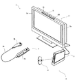
図1および図2を参照して、本発明の一実施形態に係る画像処理プログラムを実行する装置について説明する。以下、説明を具体的にするために、当該装置の一例である据置型のゲーム装置本体5を含むゲームシステムについて説明する。なお、図1は据置型のゲーム装置3を含むゲームシステム1の外観図であり、図2はゲーム装置本体5のブロック図である。以下、当該ゲームシステム1について説明する。
With reference to FIGS. 1 and 2, an apparatus for executing an image processing program according to an embodiment of the present invention will be described. Hereinafter, for the sake of specific explanation, a game system including a stationary
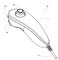
図1において、ゲームシステム1は、表示手段の一例の家庭用テレビジョン受像機(以下、モニタと記載する)2と、当該モニタ2に接続コードを介して接続する据置型のゲーム装置3とから構成される。モニタ2は、ゲーム装置本体5から出力された音声信号を音声出力するためのスピーカ2aを備える。また、ゲーム装置3は、本願発明の画像処理プログラムの一例であるゲームプログラムを記録した光ディスク4と、当該光ディスク4のゲームプログラムを実行してゲーム画面をモニタ2に表示出力させるためのコンピュータを搭載したゲーム装置本体5と、ゲーム画面に表示されたキャラクタ等を操作するゲームに必要な操作情報をゲーム装置本体5に与えるためのコントローラ7とを備えている。
In FIG. 1, a
また、ゲーム装置本体5は、無線コントローラモジュール19(図2参照)を内蔵する。無線コントローラモジュール19は、コントローラ7から無線送信されるデータを受信し、ゲーム装置本体5からコントローラ7へデータを送信して、コントローラ7とゲーム装置本体5とを無線通信によって接続する。さらに、ゲーム装置本体5には、当該ゲーム装置本体5に対して交換可能に用いられる情報記憶媒体の一例の光ディスク4が脱着される。
In addition, the
また、ゲーム装置本体5には、セーブデータ等のデータを固定的に記憶するバックアップメモリとして機能するフラッシュメモリ17(図2参照)が搭載される。ゲーム装置本体5は、光ディスク4に記憶されたゲームプログラム等を実行することによって、その結果をゲーム画像としてモニタ2に表示する。また、ゲームプログラム等は、光ディスク4に限らず、フラッシュメモリ17に予め記憶されたものを実行するようにしてもよい。さらに、ゲーム装置本体5は、フラッシュメモリ17に記憶されたセーブデータを用いて、過去に実行されたゲーム状態を再現して、ゲーム画像をモニタ2に表示することもできる。そして、ゲーム装置本体5のプレイヤは、モニタ2に表示されたゲーム画像を見ながら、コントローラ7を操作することによって、ゲーム進行を楽しむことができる。
In addition, the
コントローラ7は、無線コントローラモジュール19を内蔵するゲーム装置本体5へ、例えばBluetooth(ブルートゥース;登録商標)の技術を用いて操作情報等の送信データを無線送信する。コントローラ7は、2つのコントロールユニット(コアユニット70およびサブユニット76)が屈曲自在な接続ケーブル79を介して互いに接続されて構成されており、主にモニタ2の表示画面に表示されるオブジェクト等を操作するための操作手段である。コアユニット70およびサブユニット76は、それぞれ片手で把持可能な程度の大きさのハウジングと、当該ハウジングの表面に露出して設けられた複数個の操作ボタン(十字キーやスティック等を含む)とが設けられている。また、後述により明らかとなるが、コアユニット70は、当該コアユニット70から見た画像を撮像する撮像情報演算部74を備えている。また、撮像情報演算部74の撮像対象の一例として、モニタ2の表示画面近傍に2つのLEDモジュール(以下、マーカと記載する)8Lおよび8Rが設置される。これらマーカ8Lおよび8Rは、それぞれモニタ2の前方に向かって例えば赤外光を出力する。また、コントローラ7(例えば、コアユニット70)は、ゲーム装置本体5の無線コントローラモジュール19から無線送信された送信データを通信部75で受信して、当該送信データに応じた音や振動を発生させることもできる。
The
なお、本実施例では、コアユニット70とサブユニット76とを屈曲自在な接続ケーブル79で接続したが、サブユニット76に無線ユニットを搭載することで、接続ケーブル79をなくすこともできる。例えば、無線ユニットとしてBluetooth(登録商標)ユニットをサブユニット76に搭載することで、サブユニット76からコアユニット70へ操作データを送信することが可能になる。
In this embodiment, the
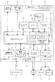
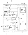
次に、図2を参照して、ゲーム装置本体5の内部構成について説明する。ゲーム装置本体5は、CPU(Central Processing Unit)10、システムLSI(Large Scale Integration)11、外部メインメモリ12、ROM/RTC(Read Only Memory/Real Time Clock)13、ディスクドライブ14、およびAV−IC(Audio Video−Integrated Circuit)15等を有する。
Next, the internal configuration of the
CPU10は、光ディスク4に記憶されたゲームプログラムを実行することによってゲーム処理を実行するものであり、ゲームプロセッサとして機能する。CPU10は、システムLSI11に接続される。システムLSI11には、CPU10の他、外部メインメモリ12、ROM/RTC13、ディスクドライブ14、およびAV−IC15が接続される。システムLSI11は、それに接続される各構成要素間のデータ転送の制御、表示すべき画像の生成、外部装置からのデータの取得等の処理を行う。なお、システムLSI11の内部構成については、後述する。揮発性の外部メインメモリ12は、光ディスク4から読み出されたゲームプログラムや、フラッシュメモリ17から読み出されたゲームプログラム等のプログラムを記憶したり、各種データを記憶したりするものであり、CPU10のワーク領域やバッファ領域として用いられる。ROM/RTC13は、ゲーム装置本体5の起動用のプログラムが組み込まれるROM(いわゆるブートROM)と、時間をカウントするクロック回路(RTC)とを有する。ディスクドライブ14は、光ディスク4からプログラムデータやテクスチャデータ等を読み出し、後述する内部メインメモリ35または外部メインメモリ12に読み出したデータを書き込む。
The
また、システムLSI11には、入出力プロセッサ31、GPU(Graphics Processor Unit)32、DSP(Digital Signal Processor)33、VRAM(Video RAM)34、および内部メインメモリ35が設けられる。図示は省略するが、これらの構成要素31〜35は、内部バスによって互いに接続される。
Further, the system LSI 11 is provided with an input /
GPU32は、描画手段の一部を形成し、CPU10からのグラフィクスコマンド(作画命令)に従って画像を生成する。VRAM34は、GPU32がグラフィクスコマンドを実行するために必要なデータ(ポリゴンデータやテクスチャデータ等のデータ)を記憶する。画像が生成される際には、GPU32は、VRAM34に記憶されたデータを用いて画像データを作成する。
The GPU 32 forms part of the drawing means and generates an image in accordance with a graphics command (drawing command) from the
DSP33は、オーディオプロセッサとして機能し、内部メインメモリ35や外部メインメモリ12に記憶されるサウンドデータや音波形(音色)データを用いて、音声データを生成する。
The
上述のように生成された画像データおよび音声データは、AV−IC15によって読み出される。AV−IC15は、AVコネクタ16を介して、読み出した画像データをモニタ2に出力するとともに、読み出した音声データをモニタ2に内蔵されるスピーカ2aに出力する。これによって、画像がモニタ2に表示されるとともに音がスピーカ2aから出力される。
The image data and audio data generated as described above are read out by the AV-
入出力プロセッサ(I/Oプロセッサ)31は、それに接続される構成要素との間でデータの送受信を実行したり、外部装置からのデータのダウンロードを実行したりする。入出力プロセッサ31は、フラッシュメモリ17、無線通信モジュール18、無線コントローラモジュール19、拡張コネクタ20、および外部メモリカード用コネクタ21に接続される。無線通信モジュール18にはアンテナ22が接続され、無線コントローラモジュール19にはアンテナ23が接続される。
The input / output processor (I / O processor) 31 transmits / receives data to / from components connected thereto and downloads data from an external device. The input /
入出力プロセッサ31は、無線通信モジュール18およびアンテナ22を介してネットワークに接続し、ネットワークに接続される他のゲーム装置や各種サーバと通信することができる。入出力プロセッサ31は、定期的にフラッシュメモリ17にアクセスし、ネットワークへ送信する必要があるデータの有無を検出し、当該データが有る場合には、無線通信モジュール18およびアンテナ22を介して当該データをネットワークに送信する。また、入出力プロセッサ31は、他のゲーム装置から送信されてくるデータやダウンロードサーバからダウンロードしたデータを、ネットワーク、アンテナ22、および無線通信モジュール18を介して受信し、受信したデータをフラッシュメモリ17に記憶する。CPU10は、ゲームプログラムを実行することにより、フラッシュメモリ17に記憶されたデータを読み出してゲームプログラムで利用する。フラッシュメモリ17には、ゲーム装置本体5と他のゲーム装置や各種サーバとの間で送受信されるデータの他、ゲーム装置本体5を利用してプレイしたゲームのセーブデータ(ゲームの結果データまたは途中データ)が記憶されてもよい。
The input /
また、入出力プロセッサ31は、アンテナ23および無線コントローラモジュール19を介して、コントローラ7から送信される操作データ等を受信し、内部メインメモリ35または外部メインメモリ12のバッファ領域に記憶(一時記憶)する。なお、内部メインメモリ35には、外部メインメモリ12と同様に、光ディスク4から読み出されたゲームプログラムや、フラッシュメモリ17から読み出されたゲームプログラム等のプログラムを記憶したり、各種データを記憶したりしてもよく、CPU10のワーク領域やバッファ領域として用いられてもかまわない。
The input /
さらに、入出力プロセッサ31には、拡張コネクタ20および外部メモリカード用コネクタ21が接続される。拡張コネクタ20は、USBやSCSIのようなインターフェースのためのコネクタであり、外部記憶媒体のようなメディアを接続したり、他のコントローラのような周辺機器を接続したり、有線の通信用コネクタを接続することによって無線通信モジュール18に替えてネットワークとの通信を行ったりすることができる。外部メモリカード用コネクタ21は、メモリカードのような外部記憶媒体を接続するためのコネクタである。例えば、入出力プロセッサ31は、拡張コネクタ20や外部メモリカード用コネクタ21を介して、外部記憶媒体にアクセスし、データを保存したり、データを読み出したりすることができる。
Furthermore, the
また、ゲーム装置本体5(例えば、前部主面)には、当該ゲーム装置本体5の電源ボタン24、ゲーム処理のリセットボタン25、光ディスク4を脱着する投入口、およびゲーム装置本体5の投入口から光ディスク4を取り出すイジェクトボタン26等が設けられている。電源ボタン24およびリセットボタン25は、システムLSI11に接続される。電源ボタン24がオンされると、ゲーム装置本体5の各構成要素に対して、図示しないACアダプタを経て電力が供給される。リセットボタン25が押されると、システムLSI11は、ゲーム装置本体5の起動プログラムを再起動する。イジェクトボタン26は、ディスクドライブ14に接続される。イジェクトボタン26が押されると、ディスクドライブ14から光ディスク4が排出される。
Further, on the game apparatus main body 5 (for example, the front main surface), the
次に、図3を参照して、コントローラ7について説明する。なお、図3は、コントローラ7の外観構成を示す斜視図である。
Next, the
図3において、コントローラ7は、コアユニット70とサブユニット76とが接続ケーブル79で接続されて構成されている。コアユニット70は、ハウジング71を有しており、当該ハウジング71に複数の操作部72が設けられている。一方、サブユニット76は、ハウジング77を有しており、当該ハウジング77に複数の操作部78が設けられている。
In FIG. 3, the
接続ケーブル79の一方端には、コアユニット70のコネクタ73に着脱自在なコネクタ791が設けられており、接続ケーブル79の他方端は固定的にサブユニット76と接続されている。そして、接続ケーブル79のコネクタ791は、コアユニット70の後面に設けられたコネクタ73と嵌合し、コアユニット70とサブユニット76とが当該接続ケーブル79を介して接続される。
A
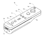
次に、図4および図5を参照して、コアユニット70について説明する。なお、図4は、コアユニット70の上面後方から見た斜視図である。図5は、コアユニット70を下面前方から見た斜視図である。
Next, the
図4および図5において、コアユニット70は、例えばプラスチック成型によって形成されたハウジング71を有している。ハウジング71は、その前後方向を長手方向とした略直方体形状を有しており、全体として大人や子供の片手で把持可能な大きさである。
4 and 5, the
ハウジング71上面の中央前面側に、十字キー72aが設けられる。この十字キー72aは、十字型の4方向プッシュスイッチであり、矢印で示す4つの方向(前後左右)に対応する操作部分が十字の突出片にそれぞれ90°間隔で配置される。プレイヤが十字キー72aのいずれかの操作部分を押下することによって前後左右いずれかの方向を選択される。例えばプレイヤが十字キー72aを操作することによって、仮想ゲーム世界に登場するプレイヤキャラクタ等の移動方向を指示したり、カーソルの移動方向を指示したりすることができる。
A cross key 72 a is provided on the center front side of the upper surface of the
なお、十字キー72aは、上述したプレイヤの方向入力操作に応じて操作信号を出力する操作部であるが、他の態様の操作部でもかまわない。例えば、リング状に4方向の操作部分を備えたプッシュスイッチとその中央に設けられたセンタスイッチとを複合した複合スイッチを上記十字キー72aの代わりに設けてもかまわない。また、ハウジング71上面から突出した傾倒可能なスティックを倒すことによって、傾倒方向に応じて操作信号を出力する操作部を上記十字キー72aの代わりに設けてもかまわない。さらに、水平移動可能な円盤状部材をスライドさせることによって、当該スライド方向に応じた操作信号を出力する操作部を、上記十字キー72aの代わりに設けてもかまわない。また、タッチパッドを、上記十字キー72aの代わりに設けてもかまわない。また、少なくとも4つの方向(前後左右)をそれぞれ示すスイッチに対して、プレイヤによって押下されたスイッチに応じて操作信号を出力する操作部を上記十字キー72aの代わりに設けてもかまわない。
Note that the cross key 72a is an operation unit that outputs an operation signal in response to the above-described direction input operation of the player, but may be an operation unit of another mode. For example, instead of the cross key 72a, a composite switch in which a push switch having a four-direction operation portion in a ring shape and a center switch provided at the center thereof may be provided. Further, an operation unit that outputs an operation signal according to the tilt direction by tilting a tiltable stick protruding from the upper surface of the
ハウジング71上面の十字キー72aより後面側に、複数の操作ボタン72b〜72gが設けられる。操作ボタン72b〜72gは、プレイヤがボタン頭部を押下することによって、それぞれの操作ボタン72b〜72gに割り当てられた操作信号を出力する操作部である。例えば、操作ボタン72b〜72dには、1番ボタン、2番ボタン、およびAボタン等としての機能が割り当てられる。また、操作ボタン72e〜72gには、マイナスボタン、ホームボタン、およびプラスボタン等としての機能が割り当てられる。これら操作ボタン72b〜72gは、ゲーム装置3が実行するゲームプログラムに応じてそれぞれの機能が割り当てられる。なお、図4に示した配置例では、操作ボタン72b〜72dは、ハウジング71上面の中央前後方向に沿って並設されている。また、操作ボタン72e〜72gは、ハウジング71上面の左右方向に沿って操作ボタン72bおよび72dの間に並設されている。そして、操作ボタン72fは、その上面がハウジング71の上面に埋没しており、プレイヤが不意に誤って押下することのないタイプのボタンである。
A plurality of
また、ハウジング71上面の十字キー72aより前面側に、操作ボタン72hが設けられる。操作ボタン72hは、遠隔からゲーム装置3本体の電源をオン/オフする電源スイッチである。この操作ボタン72hも、その上面がハウジング71の上面に埋没しており、プレイヤが不意に誤って押下することのないタイプのボタンである。
An
また、ハウジング71上面の操作ボタン72cより後面側に、複数のLED702が設けられる。ここで、コントローラ7は、他のコントローラ7と区別するためにコントローラ種別(番号)が設けられている。例えば、LED702は、コントローラ7に現在設定されている上記コントローラ種別をプレイヤに通知するために用いられる。具体的には、無線コントローラモジュール19からコントローラ7へ、複数のLED702のうち、上記コントローラ種別に対応するLEDを点灯させるための信号が送信される。
A plurality of
また、ハウジング71上面には、操作ボタン72bおよび操作ボタン72e〜72gの間に後述するスピーカ(図6のスピーカ706)からの音を外部に放出するための音抜き孔が形成されている。
In addition, a sound release hole for releasing sound from a speaker (
一方、ハウジング71下面には、凹部が形成されている。ハウジング71下面の凹部は、プレイヤがコアユニット70を把持したときに当該プレイヤの人差し指や中指が位置するような位置に形成される。そして、上記凹部の傾斜面には、操作ボタン72iが設けられる。操作ボタン72iは、例えばBボタンとして機能する操作部である。
On the other hand, a recess is formed on the lower surface of the
また、ハウジング71前面には、撮像情報演算部74の一部を構成する撮像素子743が設けられる。ここで、撮像情報演算部74は、コアユニット70が撮像した画像データを解析してその中で輝度が高い場所を判別してその場所の重心位置やサイズなどを検出するためのシステムであり、例えば、最大200フレーム/秒程度のサンプリング周期であるため比較的高速なコアユニット70の動きでも追跡して解析することができる。この撮像情報演算部74の詳細な構成については、後述する。また、ハウジング71の後面には、コネクタ73が設けられている。コネクタ73は、例えばエッジコネクタであり、例えば接続ケーブルと嵌合して接続するために利用される。
An
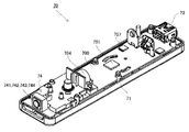
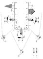
次に、図6および図7を参照して、コアユニット70の内部構造について説明する。なお、図6は、コアユニット70の上筐体(ハウジング71の一部)を外した状態を後面側から見た斜視図である。図7は、コアユニット70の下筐体(ハウジング71の一部)を外した状態を前面側から見た斜視図である。ここで、図7に示す基板700は、図6に示す基板700の裏面から見た斜視図となっている。
Next, the internal structure of the
図6において、ハウジング71の内部には基板700が固設されており、当該基板700の上主面上に操作ボタン72a〜72h、加速度センサ701、LED702、およびアンテナ754等が設けられる。そして、これらは、基板700等に形成された配線(図示せず)によってマイコン751等(図7、図10参照)に接続される。また、図示しない無線モジュール753(図10参照)およびアンテナ754によって、コアユニット70がワイヤレスコントローラとして機能する。なお、ハウジング71内部には図示しない水晶振動子が設けられており、後述するマイコン751の基本クロックを生成する。また、基板700の上主面上に、スピーカ706およびアンプ708が設けられる。
In FIG. 6, a
また、加速度センサ701は、操作ボタン72dの左側の基板700上(つまり、基板700の中央部ではなく周辺部)に設けられる。したがって、加速度センサ701は、コアユニット70の長手方向を軸とした回転に応じて、重力加速度の方向変化に加え、遠心力による成分が含まれる加速度を検出することができるので、所定の演算により、検出される加速度データからコアユニット70の動きを良好な感度でゲーム装置本体5等が判定することができる。例えば、コアユニット70は、3軸の加速度センサ701を備えている。この3軸の加速度センサ701は、3方向、すなわち、上下方向、左右方向、および前後方向で直線加速度を検知する。そして、加速度センサ701でそれぞれ検知された加速度を示すデータは、通信部75に出力される。
Further, the
一方、図7において、基板700の下主面上の前端縁に撮像情報演算部74が設けられる。撮像情報演算部74は、コアユニット70の前方から順に赤外線フィルタ741、レンズ742、撮像素子743、および画像処理回路744によって構成されており、それぞれ基板700の下主面に取り付けられる。また、基板700の下主面上の後端縁にコネクタ73が取り付けられる。さらに、基板700の下主面上にサウンドIC707およびマイコン751が設けられている。サウンドIC707は、基板700等に形成された配線によってマイコン751およびアンプ708と接続され、ゲーム装置本体5から送信されたサウンドデータに応じてアンプ708を介してスピーカ706に音声信号を出力する。そして、基板700の下主面上には、バイブレータ704が取り付けられる。このバイブレータ704は、例えば振動モータやソレノイドである。バイブレータ704が作動することによってコアユニット70に振動が発生するので、それを把持しているプレイヤの手にその振動が伝達され、いわゆる振動対応ゲームが実現できる。バイブレータ704は、ハウジング71のやや前方寄りに配置されるため、プレイヤが把持している状態において、ハウジング71が大きく振動することになり、振動を感じやすくなる。
On the other hand, in FIG. 7, an imaging
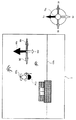
図8および図9を参照して、サブユニット76について説明する。なお、図8は、サブユニット76の一例を示す斜視図である。図9は、図8のサブユニット76の上筐体(ハウジング77の一部)を外した状態を示す斜視図である。
The
図8において、サブユニット76は、例えばプラスチック成型によって形成されたハウジング77を有している。ハウジング77は、その前後方向を長手方向とし、サブユニット76において最太部となる頭部を前方に形成した流線型の立体形状を有しており、全体として大人や子供の片手で把持可能な大きさである。
In FIG. 8, the
ハウジング77上面の上記最太部近傍に、スティック78aが設けられる。スティック78aは、ハウジング77上面から突出した傾倒可能なスティックを倒すことによって、傾倒方向や傾倒量を検出し、それに応じて操作信号を出力する操作部である。例えば、プレイヤがスティック先端を360°任意の方向に傾倒することによって任意の方向や位置を指定することができ、仮想ゲーム世界に登場するプレイヤキャラクタ等の移動方向を指示することができる。また、プレイヤは、スティック78aの傾倒量によって、プレイヤキャラクタ等の移動量を指示することができる。
A
なお、スティック78aは、プレイヤの方向入力操作に応じて操作信号を出力する操作部であるが、他の態様の操作部でもかまわない。例えば、上述した十字キーやリング状に4方向の操作部分を備えたプッシュスイッチとその中央に設けられたセンタスイッチとを複合した複合スイッチを上記スティック78aの代わりに設けてもかまわない。また、水平移動可能な円盤状部材をスライドさせることによって、当該スライド方向に応じた操作信号を出力する操作部を、上記スティック78aの代わりに設けてもかまわない。また、タッチパッドを、上記スティック78aの代わりに設けてもかまわない。また、少なくとも4つの方向(前後左右)をそれぞれ示すスイッチに対して、プレイヤによって押下されたスイッチに応じて操作信号を出力する操作部を上記スティック78aの代わりに設けてもかまわない。
The
サブユニット76のハウジング77の前面に、複数の操作ボタン78dおよび78eが設けられる。操作ボタン78dおよび78eは、プレイヤがボタン頭部を押下することによって、それぞれの操作ボタン78dおよび78eに割り当てられた操作信号を出力する操作部である。例えば、操作ボタン78dおよび78eには、XボタンおよびYボタン等としての機能が割り当てられる。これら操作ボタン78dおよび78eは、ゲーム装置3が実行するゲームプログラムに応じてそれぞれの機能が割り当てられる。なお、図8に示した配置例では、操作ボタン78dおよび78eは、ハウジング77前面の上下方向に沿って並設されている。
A plurality of
図9において、ハウジング77の内部には基板が固設されており、当該基板の上主面上にスティック78aおよび加速度センサ761等が設けられる。そして、これらは、基板等に形成された配線(図示せず)を介して接続ケーブル79と接続されている。加速度センサ761は、ハウジング77の長手方向の中央部かつ短手方向の中央部に配置されるのが好ましい。例えば、サブユニット76は、3軸の加速度センサ761を備えている。この3軸の加速度センサ761は、3方向、すなわち、上下方向、左右方向、および前後方向で直線加速度を検知する。そして、加速度センサ761でそれぞれ検知された加速度を示すデータは、接続ケーブル79を介して通信部75に出力される。
In FIG. 9, a substrate is fixed inside the
次に、図10を参照して、コントローラ7の内部構成について説明する。なお、図10は、コントローラ7の構成を示すブロック図である。
Next, the internal configuration of the
図10において、コアユニット70は、上述した操作部72、撮像情報演算部74、加速度センサ701、バイブレータ704、スピーカ706、サウンドIC707、およびアンプ708の他に、その内部に通信部75を備えている。また、サブユニット76は、上述した操作部78および加速度センサ761を備えており、接続ケーブル79とコネクタ791および73とを介して、マイコン751と接続されている。
10, the
撮像情報演算部74は、赤外線フィルタ741、レンズ742、撮像素子743、および画像処理回路744を含んでいる。赤外線フィルタ741は、コアユニット70の前方から入射する光から赤外線のみを通過させる。レンズ742は、赤外線フィルタ741を透過した赤外線を集光して撮像素子743へ出射する。撮像素子743は、例えばCMOSセンサやあるいはCCDのような固体撮像素子であり、レンズ742が集光した赤外線を撮像する。したがって、撮像素子743は、赤外線フィルタ741を通過した赤外線だけを撮像して画像データを生成する。撮像素子743で生成された画像データは、画像処理回路744で処理される。具体的には、画像処理回路744は、撮像素子743から得られた画像データを処理して高輝度部分を検知し、それらの位置座標や面積を検出した結果を示す処理結果データを通信部75へ出力する。なお、これらの撮像情報演算部74は、コアユニット70のハウジング71に固設されており、ハウジング71自体の方向を変えることによってその撮像方向を変更することができる。
The imaging
通信部75は、マイクロコンピュータ(Micro Computer:マイコン)751、メモリ752、無線モジュール753、およびアンテナ754を含んでいる。マイコン751は、処理の際にメモリ752を記憶領域として用いながら、送信データを無線送信する無線モジュール753を制御する。また、マイコン751は、アンテナ754を介して無線モジュール753が受信したゲーム装置本体5からのデータに応じて、サウンドIC707およびバイブレータ704の動作を制御する。サウンドIC707は、通信部75を介してゲーム装置本体5から送信されたサウンドデータ等を処理する。また、マイコン751は、通信部75を介してゲーム装置本体5から送信された振動データ(例えば、バイブレータ704をONまたはOFFする信号)等に応じて、バイブレータ704を作動させる。
The
コアユニット70に設けられた操作部72からの操作信号(コアキーデータ)、加速度センサ701からの加速度信号(コア加速度データ)、および撮像情報演算部74からの処理結果データは、マイコン751に出力される。また、接続ケーブル79を介して、サブユニット76に設けられた操作部78からの操作信号(サブキーデータ)および加速度センサ761からの加速度信号(サブ加速度データ)は、マイコン751に出力される。マイコン751は、入力した各データ(コアキーデータ、サブキーデータ、コア加速度データ、サブ加速度データ、処理結果データ)を無線コントローラモジュール19へ送信する送信データとして一時的にメモリ752に格納する。ここで、通信部75から無線コントローラモジュール19への無線送信は、所定の周期毎に行われるが、ゲームの処理は1/60秒を単位として行われることが一般的であるので、それよりも短い周期でデータを収集して送信を行うことが必要となる。具体的には、ゲームの処理単位は16.7ms(1/60秒)であり、ブルートゥース(Bluetooth;登録商標)で構成される通信部75の送信間隔は5msである。マイコン751は、無線コントローラモジュール19への送信タイミングが到来すると、メモリ752に格納されている送信データを一連の操作情報として、無線モジュール753へ出力する。そして、無線モジュール753は、例えばブルートゥース(登録商標)の技術に基づいて、所定周波数の搬送波を用いて操作情報で変調し、その微弱電波信号をアンテナ754から放射する。つまり、コアユニット70に設けられた操作部72からのコアキーデータ、サブユニット76に設けられた操作部78からのサブキーデータ、コアユニット70に設けられた加速度センサ701からのコア加速度データ、サブユニット76に設けられた加速度センサ761からのサブ加速度データ、および撮像情報演算部74からの処理結果データは、無線モジュール753で微弱電波信号に変調されてコアユニット70から放射される。そして、ゲーム装置3の無線コントローラモジュール19でその微弱電波信号を受信し、ゲーム装置3で当該微弱電波信号を復調や復号することによって、一連の操作情報(コアキーデータ、サブキーデータ、コア加速度データ、サブ加速度データ、および処理結果データ)を取得することができる。そして、ゲーム装置3のCPU10は、取得した操作情報とゲームプログラムとに基づいて、ゲーム処理を行う。
An operation signal (core key data) from the
次に、ゲーム装置本体5が行う具体的な処理を説明する前に、図11〜図16を参照して本ゲーム装置本体5で行うゲームの概要について説明する。なお、図11は、ゲームフィールドGF上に配置されたプレイヤキャラクタPCに対する操作方向の一例を説明するための図である。図12は、ゲームフィールドGFa上にプレイヤキャラクタPCaが配置されたときのゲーム画像および操作方向の一例を示す図である。図13は、ゲームフィールドGFb上にプレイヤキャラクタPCbが配置されたときのゲーム画像および操作方向の一例を示す図である。図14は、ゲームフィールドGFc上にプレイヤキャラクタPCcが配置されたときのゲーム画像および操作方向の一例を示す図である。図15は、ゲームフィールドGFc上に配置されたプレイヤキャラクタPCcに対して、仮想カメラCの方向を変化させたときの操作方向の一例を説明するための図である。図16は、仮想カメラCの方向を変化させたとき、ゲームフィールドGFc上にプレイヤキャラクタPCcが配置されたゲーム画像および操作方向の一例を示す図である。
Next, before describing specific processing performed by the
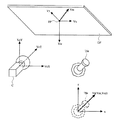
図11において、仮想ゲーム空間内に1つの立体で構成されるゲームフィールドGFが設けられている。例えば、ゲームフィールドGFは、所定の立体ポリゴンにテクスチャマッピングして形成されるゲームフィールドオブジェクトを3次元空間座標系に配置して構築される。そして、プレイヤは、ゲームフィールドGFの外周面上に配置されて当該外周面に沿って移動するプレイヤキャラクタPCを、例えばスティック78aを傾倒することによって当該プレイヤキャラクタPCを移動させてゲームを進行する。
In FIG. 11, a game field GF composed of one solid is provided in the virtual game space. For example, the game field GF is constructed by arranging game field objects formed by texture mapping on a predetermined three-dimensional polygon in a three-dimensional space coordinate system. Then, the player advances the game by moving the player character PC that is arranged on the outer peripheral surface of the game field GF and moves along the outer peripheral surface, for example, by tilting the
図11に示すように、ゲームフィールドGFには、その中心部に向かって仮想ゲーム空間の仮想重力(以下、単に重力と記載する)が設定されている。つまり、ゲームフィールドGFは、その位置に応じて重力方向が変化するように重力が設定されている。図11の例では、ゲームフィールドGFの上面(図11に示すゲームフィールドGFa)においては、当該上面からゲームフィールドGFの中心部に向かう方向(図11に示す仮想ゲーム空間の下方向)の重力が設定されている。また、ゲームフィールドGFの側面(図11に示すゲームフィールドGFb)においては、当該側面からゲームフィールドGFの中心部に向かう方向(図11に示す仮想ゲーム空間の水平(具体的には右)方向)の重力が設定されている。さらに、ゲームフィールドGFの下面(図11に示すゲームフィールドGFc)においては、当該下面からゲームフィールドGFの中心部に向かう方向(図11に示す仮想ゲーム空間の上方向)の重力が設定されている。そして、プレイヤキャラクタPCは、ゲームフィールドGFに設定された重力に引き寄せられるように外周面上に配置され、ゲームフィールドGFの何れかのフィールド面(ゲームフィールドGFa、GFb、またはGFc)に接して配置される。他の例においては、重力方向は必ずしもゲームフィールドGFの中心部に向かう方向でなくともよく、ゲームごとに適宜設定してよい。また、坂道のような箇所においては、重力方向と外周面の方線方向とが必ずしも平行でなくともよい。 As shown in FIG. 11, virtual gravity (hereinafter simply referred to as gravity) of the virtual game space is set in the game field GF toward the center thereof. That is, the game field GF is set so that the gravity direction changes according to the position. In the example of FIG. 11, on the upper surface of the game field GF (game field GFa shown in FIG. 11), gravity in the direction from the upper surface toward the center of the game field GF (downward direction of the virtual game space shown in FIG. 11) Is set. In the side surface of the game field GF (game field GFb shown in FIG. 11), the direction from the side surface toward the center of the game field GF (horizontal (specifically, right) direction of the virtual game space shown in FIG. 11) The gravity is set. Further, on the lower surface of the game field GF (game field GFc shown in FIG. 11), gravity is set in the direction from the lower surface toward the center of the game field GF (upward direction of the virtual game space shown in FIG. 11). . The player character PC is arranged on the outer peripheral surface so as to be attracted by the gravity set in the game field GF, and is arranged in contact with any field surface (game field GFa, GFb, or GFc) of the game field GF. Is done. In another example, the direction of gravity is not necessarily the direction toward the center of the game field GF, and may be set as appropriate for each game. Further, in places such as slopes, the direction of gravity and the direction of the outer peripheral surface do not necessarily have to be parallel.
図11および図12を参照して、ゲームフィールドGFa上の位置PPaに配置されたプレイヤキャラクタPCaを想定する。この場合、ゲームフィールドGFaの上方位置に配置された仮想カメラCがプレイヤキャラクタPCaを撮像する(図11に示す仮想カメラCa)ことによって、図12に示すようなゲーム画像が生成される。この状態でプレイヤがスティック78aを上方向(図12に示す方向Su)に傾倒したとき、プレイヤキャラクタPCaを仮想カメラCaから遠ざかる方向、すなわちゲーム画像において仮想ゲーム空間における手前から奥への方向(図11および図12に示す操作方向Mu)へ移動させる操作指示となる。一方、プレイヤがスティック78aを下方向(図12に示す方向Sd)に傾倒したとき、プレイヤキャラクタPCaを仮想カメラCaに近づく方向、すなわちゲーム画像において仮想ゲーム空間における奥から手前への方向(図11および図12に示す操作方向Md)へ移動させる操作指示となる。そして、プレイヤがスティック78aを左右方向(図12に示す方向SlおよびSr)にそれぞれ傾倒したとき、プレイヤキャラクタPCaを仮想カメラCaから見て左右方向(図12に示す操作方向MlおよびMr)へそれぞれ移動させる操作指示となる。図12から明らかなように、スティック78aの上下左右方向がそれぞれゲーム画像の上下左右方向となるため、プレイヤが直感的に考える方向にプレイヤの操作方向とプレイヤキャラクタPCaの移動方向とが対応付けられている。
With reference to FIG. 11 and FIG. 12, a player character PCa arranged at a position PPa on the game field GFa is assumed. In this case, when the virtual camera C arranged above the game field GFa images the player character PCa (virtual camera Ca shown in FIG. 11), a game image as shown in FIG. 12 is generated. In this state, when the player tilts the
図11および図13を参照して、ゲームフィールドGFb上の位置PPbに配置されたプレイヤキャラクタPCbを想定する。この場合、ゲームフィールドGFbの左方位置(例えば、プレイヤキャラクタPCbの直上位置)に配置された仮想カメラCがプレイヤキャラクタPCbを撮像する(図11に示す仮想カメラCb)ことによって、図13に示すようなゲーム画像が生成される。この状態でプレイヤがスティック78aを上方向(図13に示す方向Su)に傾倒したとき、プレイヤキャラクタPCbを仮想カメラCbから見て上方向(図11および図13に示す操作方向Mu)へ移動させる操作指示となる。一方、プレイヤがスティック78aを下方向(図13に示す方向Sd)に傾倒したとき、プレイヤキャラクタPCbを仮想カメラCbから見て下方向(図11および図13に示す操作方向Md)へ移動させる操作指示となる。そして、プレイヤがスティック78aを左右方向(図13に示す方向SlおよびSr)にそれぞれ傾倒したとき、プレイヤキャラクタPCbを仮想カメラCbから見て左右方向(図13に示す操作方向MlおよびMr)へそれぞれ移動させる操作指示となる。この場合も図13から明らかなように、スティック78aの上下左右方向がそれぞれゲーム画像の上下左右方向となるため、プレイヤが直感的に考える方向にプレイヤの操作方向とプレイヤキャラクタPCbの移動方向とが対応付けられている。
Referring to FIG. 11 and FIG. 13, a player character PCb placed at a position PPb on the game field GFb is assumed. In this case, the virtual camera C arranged at the left position of the game field GFb (for example, the position directly above the player character PCb) captures the player character PCb (virtual camera Cb shown in FIG. 11), and as shown in FIG. Such a game image is generated. In this state, when the player tilts the
図11および図14を参照して、ゲームフィールドGFc上の位置PPcに配置されたプレイヤキャラクタPCcを想定する。この場合、ゲームフィールドGFcの下方位置に配置された仮想カメラCがプレイヤキャラクタPCcを撮像する(図11に示す仮想カメラCc)ことによって、図14に示すようなゲーム画像が生成される。つまり、図14に示すように、上下逆になった状態でプレイヤキャラクタPCcがゲームフィールドGFの下面に引き寄せられて接しているゲーム画像が表現される。この状態でプレイヤがスティック78aを上方向(図14に示す方向Su)に傾倒したとき、プレイヤキャラクタPCcを仮想カメラCcに近づく方向、すなわちゲーム画像において仮想ゲーム空間における奥から手前への方向(図11および図14に示す操作方向Mu)へ移動させる操作指示となる。一方、プレイヤがスティック78aを下方向(図14に示す方向Sd)に傾倒したとき、プレイヤキャラクタPCcを仮想カメラCcから遠ざかる方向、すなわちゲーム画像において仮想ゲーム空間における手前から奥への方向(図11および図14に示す操作方向Md)へ移動させる操作指示となる。そして、プレイヤがスティック78aを左右方向(図14に示す方向SlおよびSr)にそれぞれ傾倒したとき、プレイヤキャラクタPCcを仮想カメラCcから見て左右方向(図14に示す操作方向MlおよびMr)へそれぞれ移動させる操作指示となる。この場合も図14から明らかなように、スティック78aの上下左右方向がそれぞれゲーム画像の上下左右方向となるため、プレイヤが直感的に考える方向にプレイヤの操作方向とプレイヤキャラクタPCcの移動方向とが対応付けられている。
Referring to FIGS. 11 and 14, a player character PCc placed at a position PPc on the game field GFc is assumed. In this case, when the virtual camera C arranged at the lower position of the game field GFc images the player character PCc (virtual camera Cc shown in FIG. 11), a game image as shown in FIG. 14 is generated. That is, as shown in FIG. 14, a game image in which the player character PCc is attracted to and touches the lower surface of the game field GF in an upside down state is represented. In this state, when the player tilts the
また、図15に示すように、プレイヤキャラクタPPcの上下が画面の上下と逆になった場合に、仮想カメラCcをその撮像方向(視線方向)を中心として回転させることによってプレイヤキャラクタPPcの上下と画面の上下が合うように表示の向きを変化させる場面を想定する。なお、図15の左側が回転前の状態、右側が回転後の状態を示している。回転させる前の仮想カメラCcは、ゲームフィールドGFcの下方位置に配置されており、プレイヤキャラクタPCcを撮像している。この仮想カメラCcが撮像することによって、図14に示すようなゲーム画像が生成される。そして、視線方向を中心として同じ位置で仮想カメラCcを図示矢印方向に180°回転させて、ゲーム画像を生成する。このような回転後の仮想カメラCcが、図15においては仮想カメラCdで示されている。 Further, as shown in FIG. 15, when the player character PPc is turned upside down with respect to the screen, the virtual camera Cc is rotated around its imaging direction (line-of-sight direction) to move the player character PPc up and down. Assume a scene in which the display orientation is changed so that the top and bottom of the screen are aligned. In addition, the left side of FIG. 15 shows the state before rotation, and the right side shows the state after rotation. The virtual camera Cc before being rotated is arranged at a position below the game field GFc and images the player character PCc. When the virtual camera Cc captures an image, a game image as shown in FIG. 14 is generated. Then, the virtual camera Cc is rotated 180 degrees in the direction of the arrow at the same position with the line-of-sight direction as the center to generate a game image. The virtual camera Cc after such rotation is indicated by a virtual camera Cd in FIG.
ゲームフィールドGFcの下方位置に配置された仮想カメラCdがプレイヤキャラクタPCcを撮像することによって、図16に示すようなゲーム画像が生成される。したがって、図16に示すように、図14と比較して上下逆転したゲーム画像が生成され、プレイヤキャラクタPCcがゲームフィールドGFの上面(実際は、ゲームフィールドGFc)の上に配置されているようなゲーム画像が表現される。 A virtual camera Cd arranged at a position below the game field GFc images the player character PCc, thereby generating a game image as shown in FIG. Therefore, as shown in FIG. 16, a game image that is inverted upside down compared to FIG. 14 is generated, and the player character PCc is placed on the upper surface of the game field GF (actually, the game field GFc). An image is represented.
プレイヤがスティック78aを上下左右方向(図16に示す方向Su、Sd、Sl、Sr)にそれぞれ傾倒したとき、上記仮想カメラCの回転に応じてプレイヤキャラクタPCcの移動方向が変化する。具体的には、プレイヤがスティック78aを方向Su(上方向)へ操作することに応じて、プレイヤキャラクタPCcを移動させる方向が、仮想カメラCcに近づく方向から仮想カメラCdから遠ざかる方向に変わる(図15および図16に示す操作方向Mu)。この場合、図16から明らかなように、操作方向に応じた移動方向の変化によって、スティック78aの上方向がゲーム画像の上方向への移動指示となるため、プレイヤが直感的に考える方向にプレイヤの操作方向とプレイヤキャラクタPCcの移動方向とが対応付けられるように変化をしていることになる。
When the player tilts the
また、プレイヤがスティック78aを方向Sd(下方向)へ操作することに応じて、プレイヤキャラクタPCcを移動させる方向が、仮想カメラCcから遠ざかる方向から仮想カメラCdに近づく方向に変わる(図15および図16に示す操作方向Md)。この場合、図16から明らかなように、操作方向に応じた移動方向の変化によって、スティック78aの下方向がゲーム画像の下方向への移動指示となるため、プレイヤが直感的に考える方向にプレイヤの操作方向とプレイヤキャラクタPCcの移動方向とが対応付けられるように変化をしていることになる。そして、プレイヤがスティック78aを左右方向(図16に示す方向SlおよびSr)にそれぞれ傾倒したとき、上記カメラ回転後においてはプレイヤキャラクタPCcを仮想カメラCdから見て左右方向(図16に示す操作方向MlおよびMr)へそれぞれ移動させる操作指示となる。
Further, in response to the player operating the
なお、本実施例においては、上述した仮想カメラCの回転に伴う移動方向の変化が、所定の条件を満たした場合に実施される。具体的には、仮想カメラCの回転前後において、プレイヤによるスティック78aの操作状態に変化がなければ、仮想カメラCの回転が行われていないものとして、仮想カメラCの回転前に設定されている操作方向に対応する移動方向が維持される。例えば、図16の例では、プレイヤがスティック78aを方向Sd(下方向)へ操作することを仮想カメラCの回転前後において維持している場合、プレイヤキャラクタPCcを移動させる方向も仮想カメラCcから遠ざかる方向に維持される(図16において上向き矢印Md)。そして、プレイヤがスティック78aの操作を緩めたり、操作方向を変更したりした時点で、上述したような移動方向の変化が実施される。このため、プレイヤが入力を維持し続けている間は、その方向の入力を始めた段階でプレイヤが意図していたゲーム空間内での方向にプレイヤキャラクタPCcを移動し続けることができ、突然操作方向が変わることによってプレイヤが混乱してしまったり、操作をミスしてしまったりすることを防ぐことができる。
In the present embodiment, the change in the moving direction accompanying the rotation of the virtual camera C described above is performed when a predetermined condition is satisfied. Specifically, before and after the rotation of the virtual camera C, if the operation state of the
プレイヤキャラクタPCがゲームフィールドGFaからゲームフィールドGFbを通ってゲームフィールドGFcまで移動するとき、仮想ゲーム空間に設定されている重力方向が最終的に180°回転する。このとき、上述のように画面上での方向に関わらず移動方向を維持している場合には、プレイヤキャラクタPCの動作に注目すると、プレイヤキャラクタPCはプレイヤキャラクタPCから見た前方へ移動し続けることになるので、姿勢が変化するのはプレイヤキャラクタPCの上方(起立方向)を示す上方向ベクトルVtおよび前方を示す前方向ベクトルVfだけであり、プレイヤキャラクタPCの横方向を示す横方向ベクトルVrに変化がないことになる。したがって、後述により明らかとなるが、重力方向が変化する領域をプレイヤキャラクタPCが通過する場合、プレイヤの方向指示入力が変化しない間は、横方向ベクトルVrを固定する処理を行っている。 When the player character PC moves from the game field GFa through the game field GFb to the game field GFc, the gravity direction set in the virtual game space is finally rotated by 180 °. At this time, when the moving direction is maintained regardless of the direction on the screen as described above, when attention is paid to the action of the player character PC, the player character PC continues to move forward as viewed from the player character PC. Therefore, the posture changes only in the upward vector Vt indicating the upward (standing direction) of the player character PC and the forward vector Vf indicating the front, and the lateral vector Vr indicating the lateral direction of the player character PC. There will be no change. Therefore, as will become clear later, when the player character PC passes through the region where the direction of gravity changes, the process of fixing the horizontal vector Vr is performed while the player's direction instruction input does not change.
次に、ゲームシステム1において行われるゲーム処理の詳細を説明する。以下、説明するゲーム処理においては、コアユニット70およびサブユニット76をそれぞれ操作する場合、サブユニット76から得られるスティック78aの方向入力(サブキーデータ)に基づいて行われる処理を一例として説明する。
Next, the details of the game process performed in the
まず、図17を参照して、ゲーム処理において用いられる主なデータについて説明する。なお、図17は、ゲーム装置本体5の外部メインメモリ12および/または内部メインメモリ35(以下、2つのメインメモリを総称して、単にメインメモリと記載する)に記憶される主なデータを示す図である。
First, main data used in the game process will be described with reference to FIG. FIG. 17 shows main data stored in the external
図17に示すように、メインメモリには、キーデータDa、プレイヤキャラクタデータDb、仮想カメラデータDc、法線ベクトルデータDd、重力ベクトルデータDe、前回重力ベクトルデータDf、側面突入状態フラグデータDg、操作ベクトルデータDh、移動ベクトルデータDi、および画像データDj等が記憶される。なお、メインメモリには、図17に示すデータの他、ゲームに登場するオブジェクト等に関するデータや仮想ゲーム空間に関するデータ(背景のデータ等)等、ゲーム処理に必要な他のデータが記憶される。 As shown in FIG. 17, the main memory has key data Da, player character data Db, virtual camera data Dc, normal vector data Dd, gravity vector data De, previous gravity vector data Df, side entry state flag data Dg, Operation vector data Dh, movement vector data Di, image data Dj, and the like are stored. In addition to the data shown in FIG. 17, the main memory stores other data necessary for game processing, such as data relating to objects appearing in the game, data relating to the virtual game space (background data, etc.), and the like.
キーデータDaは、コアユニット70やサブユニット76に設けられた操作部72および78の操作状況を示すデータであり、コアユニット70から送信データとして送信されてくる一連の操作情報に含まれる最新のコアキーデータおよびサブキーデータが記憶される。なお、ゲーム装置本体5に備える無線コントローラモジュール19は、コアユニット70から所定周期(例えば、1/200秒毎)に送信される操作情報に含まれるコアキーデータおよびサブキーデータを受信し、無線コントローラモジュール19に備える図示しないバッファに蓄えられる。その後、上記バッファに蓄えられた最新のコアキーデータおよびサブキーデータがゲーム処理周期である1フレーム毎(例えば、1/60秒毎)に読み出されて、メインメモリのキーデータDaが更新される。なお、以下の処理においては、これらコアキーデータおよびサブキーデータのうち、スティック78aの操作状況を示すサブキーデータが必要となるため、キーデータDaには当該サブキーデータを少なくとも記憶すればよい。また、キーデータDaには、少なくとも直近の2回のゲーム処理周期において取得したサブキーデータが記憶される。
The key data Da is data indicating the operation status of the
なお、後述する処理フローでは、キーデータDaがゲーム処理周期である1フレーム毎に更新される例を用いて説明するが、他の処理周期で更新されてもかまわない。例えば、コアユニット70からの送信周期毎にキーデータDaを更新し、当該更新されたキーデータをゲーム処理周期毎に利用する態様でもかまわない。この場合、キーデータDaを更新する周期と、ゲーム処理周期とが異なることになる。
In the processing flow to be described later, the key data Da is described by using an example in which it is updated every frame that is a game processing cycle. However, it may be updated in another processing cycle. For example, the key data Da may be updated every transmission cycle from the
プレイヤキャラクタデータDbは、仮想ゲーム空間に登場するプレイヤキャラクタPCの位置や姿勢を示すデータであり、プレイヤキャラクタ位置データDb1および姿勢ベクトルデータDb2を含んでいる。プレイヤキャラクタ位置データDb1は、仮想ゲーム空間におけるプレイヤキャラクタPCの位置PPを示すデータが格納される。また、姿勢ベクトルデータDb2は、仮想ゲーム空間におけるプレイヤキャラクタPCの姿勢を示すデータが格納される。例えば、姿勢ベクトルデータDb2には、プレイヤキャラクタPCの上方(起立方向)を示す上方向ベクトルVt、前方を示す前方向ベクトルVf、および横方向を示す横方向ベクトルVrを示すデータがそれぞれ格納される。 The player character data Db is data indicating the position and posture of the player character PC appearing in the virtual game space, and includes player character position data Db1 and posture vector data Db2. The player character position data Db1 stores data indicating the position PP of the player character PC in the virtual game space. The posture vector data Db2 stores data indicating the posture of the player character PC in the virtual game space. For example, the posture vector data Db2 stores data indicating an upward vector Vt indicating the upward (standing direction) of the player character PC, a forward vector Vf indicating the front, and a horizontal vector Vr indicating the horizontal direction. .
仮想カメラデータDcは、仮想ゲーム空間に配置される仮想カメラCの位置や撮像方向等を示すデータであり、カメラ位置データDc1、カメラベクトルデータDc2、および突入時カメラベクトルデータDc3を含んでいる。カメラ位置データDc1は、仮想ゲーム空間における仮想カメラCの位置を示すデータが格納される。カメラベクトルデータDc2は、仮想ゲーム空間に配置された仮想カメラCの撮像方向や向きを示すデータが格納される。例えば、カメラベクトルデータDc2は、カメラ座標系の視線方向(仮想カメラCから注視点に向かう方向)を示すカメラベクトルVcZ、カメラ座標系の右方向(仮想カメラCによって表示される表示領域の右方向)を示すカメラベクトルVcX、およびカメラ座標系の上方向(仮想カメラCによって表示される表示領域の上方向)を示すカメラベクトルVcYを示すデータがそれぞれ格納される。また、突入時カメラベクトルデータDc3は、プレイヤキャラクタPCが側面突入状態となった時点のカメラベクトルVcX、VcY、およびVcZを、カメラベクトルVcXo、VcYo、およびVcZoとして代入して、当該カメラベクトルVcXo、VcYo、およびVcZoを示すデータが一時的に格納される。 The virtual camera data Dc is data indicating the position, imaging direction, and the like of the virtual camera C arranged in the virtual game space, and includes camera position data Dc1, camera vector data Dc2, and entry-time camera vector data Dc3. The camera position data Dc1 stores data indicating the position of the virtual camera C in the virtual game space. The camera vector data Dc2 stores data indicating the imaging direction and orientation of the virtual camera C arranged in the virtual game space. For example, the camera vector data Dc2 includes a camera vector VcZ indicating a viewing direction of the camera coordinate system (a direction from the virtual camera C toward the gazing point), a right direction of the camera coordinate system (a right direction of a display area displayed by the virtual camera C) ) And a camera vector VcY indicating the upward direction of the camera coordinate system (the upward direction of the display area displayed by the virtual camera C). Further, the camera vector data Dc3 at the time of entry substitutes the camera vectors VcX, VcY, and VcZ as the camera vectors VcXo, VcYo, and VcZo when the player character PC enters the side face entry state, and the camera vector VcXo, Data indicating VcYo and VcZo is temporarily stored.
法線ベクトルデータDdは、プレイヤキャラクタPCの位置PPにおけるゲームフィールドGFの法線方向(位置PPの地形に垂直な上方向であり、典型的にはプレイヤキャラクタPCの移動方向に対して垂直となる上方向)である法線ベクトルVwを示すデータが格納される。重力ベクトルデータDeは、プレイヤキャラクタPCの位置PPにおけるゲームフィールドGFの重力方向である重力ベクトルVgを示すデータが格納される。前回重力ベクトルデータDfは、前回の処理で用いられた重力ベクトルVgを重力ベクトルVgoとして代入し、当該重力ベクトルVgoを示すデータが格納される。側面突入状態フラグデータDgは、プレイヤキャラクタPCが側面突入状態にあるか否かを示す側面突入状態フラグFの状態を示すデータが格納される。ここで、側面突入状態とは、上述のように、プレイヤキャラクタPCの移動方向を維持し続ける状態であって、例えばゲームフィールドGFの上面から側面に突入し、さらに下面へと移動していく場合などにおける状態のことである。 The normal vector data Dd is the normal direction of the game field GF at the position PP of the player character PC (the upward direction perpendicular to the terrain at the position PP, and is typically perpendicular to the moving direction of the player character PC. Data indicating the normal vector Vw (upward) is stored. The gravity vector data De stores data indicating a gravity vector Vg which is the gravity direction of the game field GF at the position PP of the player character PC. In the previous gravity vector data Df, the gravity vector Vg used in the previous process is substituted as the gravity vector Vgo, and data indicating the gravity vector Vgo is stored. The side entry state flag data Dg stores data indicating the state of the side entry state flag F indicating whether or not the player character PC is in the side entry state. Here, as described above, the side entry state is a state in which the moving direction of the player character PC is maintained, for example, when the player enters the side surface from the upper surface of the game field GF and further moves to the lower surface. It is a state in such as.
操作ベクトルデータDhは、プレイヤの方向入力の方向や操作量を示すデータが格納される。例えば、スティック78aの傾倒方向および傾倒量(傾倒角度)に応じてプレイヤキャラクタPCの移動方向および移動速度が指示される場合、キーデータDaに基づいてスティック78aの傾倒方向および傾倒量に応じた操作ベクトルVsが算出され、当該操作ベクトルVsを示すデータが操作ベクトルデータDhに格納される。操作ベクトルVsは、具体的にはスティック78aの上下方向の傾倒量、左右方向の傾倒量の2つの値で表される2次元ベクトルである。移動ベクトルデータDiは、仮想ゲーム空間においてプレイヤキャラクタPCが移動する方向および速度を示すデータが格納される。例えば、操作ベクトルVsに応じて、仮想ゲーム空間においてプレイヤキャラクタPCが移動する方向および速度を示す移動ベクトルVmが算出され、当該移動ベクトルVmを示すデータが移動ベクトルデータDiに格納される。
The operation vector data Dh stores data indicating the direction input direction and the operation amount of the player. For example, when the moving direction and moving speed of the player character PC are instructed according to the tilt direction and tilt amount (tilt angle) of the
画像データDjは、プレイヤキャラクタ画像データDj1および地形画像データDj2等を含んでいる。プレイヤキャラクタ画像データDj1は、仮想ゲーム空間の位置PPにプレイヤキャラクタPCを配置してゲーム画像を生成するためのデータである。地形画像データDj2は、仮想ゲーム空間にゲームフィールドGFを配置してゲーム画像を生成するためのデータである。 The image data Dj includes player character image data Dj1, terrain image data Dj2, and the like. The player character image data Dj1 is data for generating a game image by placing the player character PC at the position PP in the virtual game space. The topographic image data Dj2 is data for generating a game image by arranging the game field GF in the virtual game space.
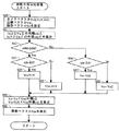
次に、図18〜図20を参照して、ゲーム装置本体5において行われるゲーム処理の詳細を説明する。なお、図18は、ゲーム装置本体5において実行されるゲーム処理の流れを示すフローチャートである。図19は、図18におけるステップ46および51の移動方向算出処理の詳細な動作を示すサブルーチンである。図20は、図18におけるステップ55の側面突入検出処理の詳細な動作を示すサブルーチンである。なお、図18〜図20に示すフローチャートにおいては、ゲーム処理のうち、プレイヤがスティック78aを操作することに応じてプレイヤキャラクタPCを移動させる処理について説明し、本願発明と直接関連しない他のゲーム処理については詳細な説明を省略する。また、図18〜図20では、CPU10が実行する各ステップを「S」と略称する。
Next, with reference to FIGS. 18 to 20, the details of the game processing performed in the
ゲーム装置本体5の電源が投入されると、ゲーム装置本体5のCPU10は、ブートROM(例えば、ROM/RTC13)に記憶されている起動プログラムを実行し、これによってメインメモリ等の各ユニットが初期化される。そして、光ディスク4に記憶されたゲームプログラムがメインメモリに読み込まれ、CPU10によって当該ゲームプログラムの実行が開始される。図18〜図20に示すフローチャートは、以上の処理が完了した後に行われるゲーム処理を示すフローチャートである。
When the power of the
図18において、CPU10は、ゲーム処理の初期設定を行い(ステップ40)、次のステップに処理を進める。上記ステップ40における初期設定では、ゲームフィールドオブジェクトを3次元空間座標系に配置してゲームフィールドGFを構築する。なお、ゲームフィールドGFは、上述したような立体形状を有しており、当該立体外周面の各地点に対して、それぞれ上述したような重力が設定される。それぞれの地点における重力は、例えば上記立体の中心付近を向くように設定される。また、プレイヤキャラクタPCや他のオブジェクトをゲームフィールドGF外周面上の所定位置に配置し、プレイヤキャラクタPCの位置PPおよび姿勢を示すデータをプレイヤキャラクタデータDbに格納する。そして、プレイヤキャラクタPC等が配置されたゲームフィールドGFに対して、予め決められた初期位置に仮想カメラCを配置してゲーム画像をモニタ2に表示し、当該仮想カメラCの位置やカメラベクトルを示すデータを仮想カメラデータDcに格納する。また、CPU10は、各ゲームパラメータを初期化(例えば、上述したパラメータを除いた各ゲームパラメータを0に初期化)する。
In FIG. 18, the
次に、CPU10は、プレイヤキャラクタPCの位置PPに応じて仮想カメラCを設定し(ステップ41)、次のステップに処理を進める。つまり、カメラ位置データDc1、カメラベクトルデータDc2を適宜設定する。例えば、CPU10は、プレイヤキャラクタPC等が配置されたゲームフィールドGFに対して、少なくともプレイヤキャラクタPCが撮像範囲内(例えば、撮像範囲の中央)となるように仮想カメラCを配置して(図11参照)ゲーム画像をモニタ2に表示し、当該仮想カメラCの位置やカメラベクトルを示すデータを仮想カメラデータDcに格納する。なお、本実施例においては、上記ステップ41において、仮想カメラCの位置をプレイヤキャラクタPCの移動に常に追従するように設定する(図11参照)。また、上記ステップ41において、プレイヤキャラクタPCの位置PP等が所定の条件を満たせば、仮想カメラCの方向をその視線方向を中心として180°回転するまで、フレーム毎に徐々に角度を変化させるように設定する(図15参照)。このように、仮想カメラCの視体積内にプレイヤキャラクタPCが含まれて、モニタ2にプレイヤキャラクタPCが表示されるように仮想カメラCの位置および姿勢が設定される。
Next, the
次に、CPU10は、サブキーデータを取得して(ステップ42)、次のステップに処理を進める。例えば、CPU10は、コアユニット70から受信した最新の操作情報に含まれるキーデータを用いて、キーデータDaを更新する。具体的には、コアユニット70から受信した最新の操作情報に含まれるサブキーデータ(特に、スティック78aの操作状況を示すデータ)を用いて、キーデータDaを更新する。なお、上記ステップ42で取得したサブキーデータは、最新のデータとしてキーデータDaに記憶される。また、上記ステップ42の実行前までに最新のデータとしてキーデータDaに記憶されていたサブキーデータは、前回のデータとして取り扱われて引き続きキーデータDaに記憶される。このようにキーデータDaには、少なくとも直近の2回のゲーム処理周期において取得したサブキーデータが記憶される。
Next, the
次に、CPU10は、キーデータDaを参照して、プレイヤからの方向入力があるか否かを判断する(ステップ43)。例えば、CPU10は、キーデータDaに格納されているサブキーデータが、何れかの方向にスティック78aが傾倒されていることを示す場合、方向入力があると判断する。一方、CPU10は、キーデータDaに格納されているサブキーデータが、スティック78aが傾倒されていないニュートラル状態であることを示す場合、方向入力がないと判断する。そして、CPU10は、方向入力がある場合、次のステップ44に処理を進める。一方、CPU10は、方向入力がない場合、側面突入状態を解除して、次のステップ57に処理を進める。具体的には、CPU10は、側面突入状態フラグデータDgに記憶されている側面突入状態フラグFをOFFに設定する。
Next, the
ステップ44において、CPU10は、プレイヤキャラクタPCが側面突入状態にあるか否かを判断する。具体的には、CPU10は、側面突入状態フラグデータDgを参照し、側面突入状態フラグFがONである場合にプレイヤキャラクタPCが側面突入状態にあると判断する。そして、CPU10は、側面突入状態にある場合、次のステップ45に処理を進める。一方、CPU10は、側面突入状態にない場合、次のステップ51に処理を進める。
In step 44, the
ステップ45において、CPU10は、プレイヤによる方向入力の変化が閾値以内であるか否かを判断する。そして、CPU10は、方向入力の変化が閾値以内である場合、次のステップ46に処理を進める。一方、CPU10は、方向入力の変化が閾値を越えている場合、次のステップ50に処理を進める。例えば、上記ステップ45においては、キーデータDaに記憶された最新のサブキーデータが示すスティック78aの傾倒状況(例えば、傾倒方向や傾倒量)と、前回のサブキーデータが示すスティック78aの傾倒状況とが比較される。そして、両者の差が方向入力操作を変化させたレベルであることを判定するための閾値が設けられており、当該差が閾値以内であるときに方向入力操作が不変であると認識している。
In
ステップ50において、CPU10は、側面突入状態を解除して、次のステップ51に処理を進める。具体的には、CPU10は、側面突入状態フラグデータDgに記憶されている側面突入状態フラグFをOFFに設定する。ここで、上記ステップ50は、プレイヤキャラクタPCが側面突入状態であり(ステップ44でYes)、かつ、方向入力の変化が閾値を越えている場合(ステップ45でNo)に実行される処理であり、プレイヤキャラクタPCが側面突入状態であってもプレイヤの方向入力操作が変化すると側面突入状態が解除されることになる。
In step 50, the
プレイヤキャラクタPCが側面突入状態にない場合(ステップ44でNoまたはステップ45でNo)、ステップ51が実行される。ステップ51において、CPU10は、プレイヤキャラクタPCの移動方向を決定する処理を行う。以下、図19を参照して、移動方向決定処理について説明する。
If the player character PC is not in the side entry state (No in Step 44 or No in Step 45), Step 51 is executed. In step 51, the
図19において、CPU10は、カメラベクトルVcX、VcY、およびVcZと、法線ベクトルVwと、操作ベクトルVsとを設定し(ステップ80)、処理を次のステップに進める。
In FIG. 19, the
図21および図22を参照して、上記ステップ80におけるカメラベクトルVcX、VcY、およびVcZと、法線ベクトルVwと、操作ベクトルVsとの設定例について説明する。後述により明らかとなるが、当該移動方向決定処理は、プレイヤキャラクタPCが側面突入状態にない場合と、側面突入状態である場合との両方において行われる処理であるが、移動方向の決定に用いられるカメラベクトルが異なっている。CPU10は、プレイヤキャラクタPCが側面突入状態にない場合、上記ステップ41で設定されたカメラベクトルVcX、VcY、およびVcZ(すなわち、カメラベクトルデータDc2に記憶されているカメラベクトル)を、そのまま以下の処理で用いるパラメータとして上記ステップ80で設定する。一方、CPU10は、プレイヤキャラクタPCが側面突入状態である場合、突入時カメラベクトルデータDc3に記憶されているカメラベクトルVcXo、VcYo、およびVcZoを、それぞれカメラベクトルVcX、VcY、およびVcZの代わりのパラメータとして取り扱って上記ステップ80で設定する。
A setting example of the camera vectors VcX, VcY, and VcZ, the normal vector Vw, and the operation vector Vs in
また、CPU10は、プレイヤキャラクタ位置データDb1を参照して、位置PPにおけるゲームフィールドGFの法線ベクトルVw(位置PPの地形に垂直な上方向であり、典型的にはプレイヤキャラクタPCの移動方向(移動ベクトルVm)に対して垂直となる上方向を示すベクトル)を算出する。そして、CPU10は、当該法線ベクトルVwを示すデータを法線ベクトルデータDdに記憶する。また、CPU10は、キーデータDaに記憶された最新のサブキーデータが示すスティック78aの傾倒方向および傾倒量を用いて、操作ベクトルVsを算出する。そして、CPU10は、当該操作ベクトルVsを示すデータを操作ベクトルデータDiに記憶する。ここで、必要に応じて、法線ベクトルVwに代えて、位置PPにおける重力ベクトルを反転させたベクトル(反重力ベクトル)や、重力ベクトルと法線ベクトルとの2つのベクトルを適宜調整することによって算出したベクトルを法線ベクトルデータDdに格納するようにしても、適宜移動方向を定めることが可能である。
Further, the
図19に戻り、CPU10は、上記ステップ80の処理の後、内積zdnおよびydnを算出し(ステップ81)、次のステップに処理を進める。具体的には、CPU10は、上記ステップ80で設定されたカメラベクトルVcYおよびVcZと、法線ベクトルVmとを用いて、−VcZとVwとの内積を内積zdn、VcYとVwとの内積を内積ydnとして算出する。つまり、内積zdnは法線ベクトルVwにおけるカメラ座標系の反視線方向(−VcZ方向)成分を示すパラメータであり、内積ydnは法線ベクトルVwにおけるカメラ座標系の上方向(VcY方向)成分を示すパラメータとなる。
Returning to FIG. 19, after the process of
次に、CPU10は、内積zdnの絶対値が内積ydnの絶対値より大きいか否かを判断する(ステップ82)。そして、CPU10は、|zdn|>|ydn|の場合、次のステップ83に処理を進める。一方、CPU10は、|zdn|≦|ydn|の場合、次のステップ86に処理を進める。ここで、上記ステップ82は、法線ベクトルVwの方向がカメラ座標の視線方向に近いか上下方向に近いかを判定している。すなわち、上記ステップ82では、プレイヤキャラクタPCがゲームフィールドGF上で起立している場合、仮想カメラCがプレイヤキャラクタPCの直上方向に近い位置から撮像しているか、プレイヤキャラクタPCの横方向に近い位置から撮像しているかを判定していることになる。そして、CPU10は、法線ベクトルVwの方向がカメラ座標の視線方向に近い場合にステップ83に処理を進め、法線ベクトルVwの方向がカメラ座標の上下方向に近い場合にステップ86に処理を進めている。
Next, the
ステップ83において、CPU10は、内積zdnが0以上か否かを判断する。そして、CPU10は、zdn≧0の場合、ベクトルVo=VcYとしてベクトルVoを設定し(ステップ84)、次のステップ89に処理を進める。一方、CPU10は、zdn<0の場合、ベクトルVo=−VcYとしてベクトルVoを設定し(ステップ85)、次のステップ89に処理を進める。
In
一方、ステップ86において、CPU10は、内積ydnが0以上か否かを判断する。そして、CPU10は、ydn≧0の場合、ベクトルVo=VcZとしてベクトルVoを設定し(ステップ87)、次のステップ89に処理を進める。一方、CPU10は、ydn<0の場合、ベクトルVo=−VcZとしてベクトルVoを設定し(ステップ88)、次のステップ89に処理を進める。
On the other hand, in
ステップ89において、CPU10は、方向ベクトルVxおよびVyを算出し、次のステップに処理を進める。ここで、図21および図22に示すように、方向ベクトルVxは、スティック78aを右方向(図12等で示す方向Sr)に傾倒させた操作に対応する仮想ゲーム空間の方向(具体的には、プレイヤキャラクタPCの移動方向)を示す方向パラメータである。また、方向ベクトルVyは、スティック78aを上方向(図12等で示す方向Su)に傾倒させた操作に対応する仮想ゲーム空間の方向を示す方向パラメータである。そして、CPU10は、方向ベクトルVxを、ベクトルVoと法線ベクトルVwとの外積、すなわち、
Vx = Vo × Vw
によって算出する。また、CPU10は、方向ベクトルVyを、カメラベクトルVcXの逆方向ベクトル(−VcX)と法線ベクトルVwとの外積、すなわち、
Vy = −VcX × Vw
によって算出する。
In
Vx = Vo x Vw
Calculated by Further, the
Vy = −VcX × Vw
Calculated by
次に、CPU10は、プレイヤキャラクタPCの移動ベクトルVmを算出して移動ベクトルデータDiを更新し(ステップ90)、当該サブルーチンによる処理を終了する。例えば、CPU10は、移動ベクトルVmを
Vm = Vx * Vsx + Vy * Vsy
によって算出する。ここで、図21および図22に示すように、Vsxは操作ベクトルVsのx方向(スティック78aを右へ傾倒させる方向)成分を示し、Vsyは操作ベクトルVsのy方向(スティック78aを上へ傾倒させる方向であり、x方向と直交する方向)成分を示している。つまり、プレイヤの方向入力の方向を示す操作ベクトルVsは、直交する2軸方向(x方向およびy方向)を基準としたパラメータであり、上記方向ベクトルVxおよびVyをそれぞれ当該2軸方向に関連付けて移動ベクトルVmを算出している。
Next, the
Calculated by Here, as shown in FIGS. 21 and 22, Vsx represents the x direction component (direction in which the
ここで、上述した移動方向決定処理における基本原理について説明する。上述した処理においては、互いに直交する3つのカメラベクトルVcX、VcY、およびVcZの何れか2つと、移動方向に対して必ず垂直となる法線ベクトルVwとの外積を用いて、操作ベクトルVsに対応する仮想ゲーム空間の方向(移動ベクトルVm)を求めている。ここで、図21および図22に示すように、上述した処理は、ゲームフィールドGFの法線方向(もしくは重力方向)が表示画面に対して上下または前後方向に設定される、すなわち法線ベクトルVwの方向がカメラ座標におけるVcY−VcZ平面と平行であることを前提としている。したがって、表示されるゲーム画像において、位置PPからゲームフィールドGFに沿った上方向となる方向ベクトルVyは、法線ベクトルVwおよびカメラベクトルVcXに対して直交するベクトルとなる。すなわち、方向ベクトルVyは、カメラベクトルVcXの逆方向ベクトル(−VcX)と法線ベクトルVwとの外積によって求めることができる。 Here, the basic principle in the movement direction determination process described above will be described. In the processing described above, the operation vector Vs is handled using the outer product of any two of the three camera vectors VcX, VcY, and VcZ orthogonal to each other and the normal vector Vw that is always perpendicular to the moving direction. The direction of the virtual game space to be played (movement vector Vm) is obtained. Here, as shown in FIG. 21 and FIG. 22, in the above-described processing, the normal direction (or gravity direction) of the game field GF is set to the vertical or front-rear direction with respect to the display screen. Is assumed to be parallel to the VcY-VcZ plane in camera coordinates. Accordingly, in the displayed game image, the direction vector Vy extending upward from the position PP along the game field GF is a vector orthogonal to the normal vector Vw and the camera vector VcX. That is, the direction vector Vy can be obtained by the outer product of the reverse vector (−VcX) of the camera vector VcX and the normal vector Vw.
また、表示されるゲーム画像において、位置PPからゲームフィールドGFに沿った右方向となる方向ベクトルVxは、法線ベクトルVwおよびカメラベクトルVcYまたはVcZに対して直交するベクトルとなる。しかしながら、法線ベクトルVwの方向がカメラ座標におけるVcY−VcZ平面と平行であることを前提にして、法線ベクトルVwとカメラ座標との位置関係が仮想カメラCの移動等に応じて変化する。つまり、カメラベクトルVcYおよびVcZと法線ベクトルVwとの位置関係が、仮想カメラCの移動や撮像角度の変化に応じて変化する。本実施例では、カメラベクトルVcYおよびVcZから法線ベクトルVwの方向との差が大きい(内積値が小さい)一方を選択し、当該選択された一方(ベクトルVo)と法線ベクトルVwとの外積によって、方向ベクトルVxを求めている。なお、方向ベクトルVxおよびVyを求める際のカメラベクトルVcX、VcY、およびVcZの正負は、所望の方向に直交する方向ベクトルVxおよびVyを外積によって求めるための符号調整である。例えば、内積値の絶対値が小さい結果となったカメラベクトルVcYおよびVcZの一方について、当該内積値の正負に応じて当該一方のカメラベクトルVcYまたはVcZを反転させて符号調整している。 Further, in the displayed game image, the direction vector Vx which is the right direction from the position PP along the game field GF is a vector orthogonal to the normal vector Vw and the camera vector VcY or VcZ. However, assuming that the direction of the normal vector Vw is parallel to the VcY-VcZ plane in the camera coordinates, the positional relationship between the normal vector Vw and the camera coordinates changes according to the movement of the virtual camera C and the like. That is, the positional relationship between the camera vectors VcY and VcZ and the normal vector Vw changes according to the movement of the virtual camera C and the change in the imaging angle. In this embodiment, one of the camera vectors VcY and VcZ that has a large difference from the direction of the normal vector Vw (small inner product value) is selected, and the outer product of the selected one (vector Vo) and the normal vector Vw. Thus, the direction vector Vx is obtained. Note that the sign of the camera vectors VcX, VcY, and VcZ when obtaining the direction vectors Vx and Vy is a sign adjustment for obtaining the direction vectors Vx and Vy orthogonal to the desired direction by an outer product. For example, with respect to one of the camera vectors VcY and VcZ that has resulted in a small absolute value of the inner product value, the sign adjustment is performed by inverting the one camera vector VcY or VcZ according to the sign of the inner product value.
このように、本実施例では、カメラベクトルVcX、VcY、およびVcZと法線ベクトルVwとの内積および外積を用いることによって、プレイヤの方向入力の基準入力方向(xおよびy方向)に応じた仮想ゲーム空間における基準方向(方向ベクトルVxおよびVy)を算出している。そして、当該基準方向に基づいて、プレイヤの方向入力に応じた移動ベクトルVmを算出することによって、プレイヤの方向入力に直感的に対応付けられた移動方向を算出している。これによって、重力方向(法線方向)が様々な方向に設定されているゲームフィールドを用いた仮想ゲーム空間においても、直感的な方向入力操作が実現可能となり、プレイヤに操作の混乱を与えることもない。さらに、上記仮想ゲーム空間環境において、所定条件を満たすときに仮想カメラを回転させる状況であっても、直感的な方向入力操作が実現可能となり、プレイヤに操作の混乱を与えることもない。 As described above, in this embodiment, by using the inner product and outer product of the camera vectors VcX, VcY, and VcZ and the normal vector Vw, a virtual corresponding to the reference input direction (x and y directions) of the player's direction input is used. Reference directions (direction vectors Vx and Vy) in the game space are calculated. Based on the reference direction, a movement vector Vm corresponding to the player's direction input is calculated to calculate a movement direction intuitively associated with the player's direction input. As a result, even in a virtual game space using a game field in which the gravity direction (normal direction) is set in various directions, an intuitive direction input operation can be realized, which may cause confusion for the player. Absent. Furthermore, even in a situation where the virtual camera is rotated when a predetermined condition is satisfied in the virtual game space environment, an intuitive direction input operation can be realized, and the operation is not disrupted to the player.
なお、上述した移動方向決定処理では、カメラベクトルVcX、VcY、およびVcZのうち、カメラベクトルVcYおよびVcZの何れか一方と、カメラベクトルVcXとを用いて2つの方向ベクトルVxおよびVyを算出しているが、他の態様でカメラベクトルを選択して算出してもかまわない。例えば、上述した移動方向決定処理では、法線ベクトルVwの方向がカメラ座標におけるVcY−VcZ平面と平行であることを前提にしているために、カメラベクトルVcXを用いることを必須としているが、カメラ座標系と法線ベクトルVwとの位置関係によって、他のカメラベクトルを用いることを必須としてもよい。具体的には、ゲームフィールドGFの重力方向(法線方向)が表示画面に対して左右または前後方向に設定される、すなわち法線ベクトルVwの方向がカメラ座標におけるVcX−VcZ平面と平行であることを前提とする。この場合、カメラベクトルVcX、VcY、およびVcZのうち、カメラベクトルVcXおよびVcZの何れか一方と法線ベクトルVwとの外積、およびカメラベクトルVcYと法線ベクトルVwとの外積を用いてそれぞれ2つの方向ベクトルVxおよびVyを算出すればよい。 In the moving direction determination process described above, two direction vectors Vx and Vy are calculated using either one of the camera vectors VcY, VcZ and the camera vector VcX among the camera vectors VcX, VcY, and VcZ. However, it may be calculated by selecting a camera vector in another manner. For example, in the moving direction determination process described above, since it is assumed that the direction of the normal vector Vw is parallel to the VcY-VcZ plane in the camera coordinates, it is essential to use the camera vector VcX. Depending on the positional relationship between the coordinate system and the normal vector Vw, it may be necessary to use another camera vector. Specifically, the gravity direction (normal direction) of the game field GF is set to the left or right or front-rear direction with respect to the display screen, that is, the direction of the normal vector Vw is parallel to the VcX-VcZ plane in camera coordinates. Assuming that. In this case, of the camera vectors VcX, VcY, and VcZ, two of the camera vectors VcX and VcZ and the normal vector Vw and the outer product of the camera vector VcY and the normal vector Vw are used. The direction vectors Vx and Vy may be calculated.
図18に戻り、上記ステップ51の移動方向決定処理の後、CPU10は、プレイヤキャラクタPCが姿勢変化する際の回転軸を未固定に設定する(ステップ52)。そして、CPU10は、上記ステップ51で算出された移動ベクトルVmに基づいて、プレイヤキャラクタPCを移動させ(ステップ53)、当該プレイヤキャラクタPCの姿勢を決定して(ステップ54)、次のステップ55に処理を進める。例えば、CPU10は、ゲームフィールドGF上を移動ベクトルVmに基づいてプレイヤキャラクタPCを移動させて新たな位置PPを算出して、プレイヤキャラクタ位置データDb1を更新する。そして、CPU10は、新たに算出された位置PPおよびプレイヤからの操作入力に応じてプレイヤキャラクタPCの姿勢を決定して、姿勢ベクトルデータDb2を更新する。ここで、図23に示すように、プレイヤキャラクタPCにはその姿勢を示すパラメータとしてベクトルVt、Vf、およびVrが設定されている。具体的には、プレイヤキャラクタPCの上方(起立方向)を示す上方向ベクトルVt、前方を示す前方向ベクトルVf、および横方向を示す横方向ベクトルVrによって、プレイヤキャラクタPCの姿勢が定義される。上記ステップ54では、新たに算出された位置PPおよびプレイヤからの操作入力に応じて、これら上方向ベクトルVt、前方向ベクトルVf、および横方向ベクトルVrを決定して、姿勢ベクトルデータDb2を更新する。
Returning to FIG. 18, after the moving direction determination process in step 51, the
一方、プレイヤキャラクタPCが側面突入状態であり(ステップ44でYes)、かつ、方向入力の変化が閾値以内(すなわち、プレイヤの方向入力操作が不変)である場合(ステップ45でYes)、CPU10は、プレイヤキャラクタPCの移動方向を決定する処理を行って(ステップ46)、次のステップに処理を進める。このステップ46で行う移動方向決定処理は、上述したステップ51で行う移動方向決定処理と同様であるため、詳細な説明を省略する。ただし、ステップ46で行う移動方向決定処理においては、プレイヤキャラクタPCが側面突入状態であるため、突入時カメラベクトルデータDc3に記憶されているカメラベクトルVcXo、VcYo、およびVcZoが、それぞれカメラベクトルVcX、VcY、およびVcZとして取り扱われる。
On the other hand, if the player character PC is in the side entry state (Yes in step 44) and the change in direction input is within a threshold (that is, the player's direction input operation is unchanged) (Yes in step 45), the
次に、CPU10は、上記ステップ46の移動方向決定処理の後、プレイヤキャラクタPCが姿勢変化する際の回転軸を固定に設定する(ステップ47)。そして、CPU10は、上記ステップ46で算出された移動ベクトルVmに基づいて、プレイヤキャラクタPCを移動させ(ステップ48)、当該プレイヤキャラクタPCの姿勢を決定して(ステップ49)、次のステップ55に処理を進める。
Next, after the movement direction determination process in
例えば、上記ステップ48において、CPU10は、ゲームフィールドGF上を移動ベクトルVmに基づいてプレイヤキャラクタPCを移動させて新たな位置PPを算出して、プレイヤキャラクタ位置データDb1を更新する。ここで、ステップ48におけるプレイヤキャラクタPCの移動方向は、側面突入状態に移行した時点のカメラベクトルに基づいて算出される。したがって、側面突入状態期間で仮想カメラCが移動または回転しても、当該移動や回転が行われてない状態を仮定してプレイヤキャラクタPCの移動方向が算出される。
For example, in
また、上記ステップ49において、CPU10は、新たに算出された位置PPおよびプレイヤからの操作入力に応じてプレイヤキャラクタPCの姿勢を決定して、姿勢ベクトルデータDb2を更新する。ここで、上記ステップ49の姿勢決定処理は、プレイヤキャラクタPCの姿勢を変化させる際、横方向ベクトルVrの方向を固定して他の上方向ベクトルVtおよび前方向ベクトルVfの方向を回転させる。ここで、後述により明らかとなるが、プレイヤキャラクタPCに作用する重力方向が変化し、かつ、方向入力操作に変化がないときに、側面突入状態に設定される。そして、図11等を用いて説明したように、このような環境におけるプレイヤキャラクタPCの動作に注目すると、プレイヤキャラクタPCの姿勢が変化するのはプレイヤキャラクタPCの上方向ベクトルVtおよび前方向ベクトルVfだけであり、プレイヤキャラクタPCの横方向ベクトルVrに変化がない。したがって、上記ステップ49における姿勢決定処理においては、プレイヤキャラクタPCの姿勢を決める上方向ベクトルVt、前方向ベクトルVf、および横方向ベクトルVrのうち、1つ(横方向ベクトルVr)を固定して、重力変化時におけるプレイヤキャラクタPCの姿勢変化を制御している。
In step 49, the
ステップ55において、CPU10は、側面突入検出処理を行い、次のステップ57に処理を進める。以下、図20を参照して、側面突入検出処理の詳細な動作について説明する。
In step 55, the
図20において、CPU10は、現在の位置PPに設定されている重力ベクトルVgを取得して重力ベクトルデータDeを更新し(ステップ91)、次のステップに処理を進める。上述したように、ゲームフィールドGFには、その中心部に向かって仮想ゲーム空間の重力が設定されている。そして、上記ステップ91においては、位置PPに設定されている重力方向(つまり、プレイヤキャラクタPCに作用している仮想重力の方向)を示す重力ベクトルVgを取得する。
In FIG. 20, the
次に、CPU10は、側面突入状態フラグデータDgを参照して、プレイヤキャラクタPCが側面突入状態にあるか否かを判断する(ステップ92)。そして、CPU10は、側面突入状態でない場合、次のステップ93に処理を進める。一方、CPU10は、側面突入状態である場合、次のステップ99に処理を進める。
Next, the
ステップ93において、CPU10は、重力ベクトルデータDeに格納されている重力ベクトルVgと、前回重力ベクトルデータDfに格納されている重力ベクトルVgoとが等しいか否かを判断する。そして、CPU10は、Vg≠Vgoの場合、次のステップ94に処理を進める。一方、CPU10は、Vg=Vgoの場合、次のステップ99に処理を進める。ここで、前回重力ベクトルデータDfに格納されている重力ベクトルVgoは、前回の処理において取得された重力ベクトルVgであり、上記ステップ93ではプレイヤキャラクタPCに作用する重力の方向が変化したか否かを検出していることになる。
In
ステップ94において、CPU10は、重力回転軸ベクトルVgrを算出して、次のステップに処理を進める。ここで、重力回転軸ベクトルVgrは、重力の変化の回転軸を示すベクトルであり、重力ベクトルVgおよび重力ベクトルVgoに対して互いに垂直なベクトルを算出することによって求められる。
In step 94, the
次に、CPU10は、プレイヤキャラクタPCの上方向ベクトルVt、前方向ベクトルVf、および横方向ベクトルVrそれぞれの方向から、重力回転軸ベクトルVgrが示す回転軸方向に最も近いものを選択し(ステップ95)、選択された方向を示すベクトルが横方向ベクトルVrであるか否かを判断する(ステップ96)。そして、CPU10は、横方向ベクトルVrが選択された場合、次のステップ97に処理を進める。一方、CPU10は、上方向ベクトルVtまたは前方向ベクトルVfが選択された場合、次のステップ99に処理を進める。
Next, the
ステップ97において、CPU10は、CPU10は、側面突入状態に設定して、次のステップに処理を進める。具体的には、CPU10は、側面突入状態フラグデータDgに記憶されている側面突入状態フラグFをONに設定する。
In step 97, the
次に、CPU10は、カメラベクトルデータDc2に格納されているカメラベクトルVcX、VcY、およびVcZを参照して、それぞれの値をそれぞれカメラベクトルVcXo、VcYo、およびVcZoに代入して突入時カメラベクトルデータDc3に格納し(ステップ98)、次のステップ99に処理を進める。
Next, the
ステップ99において、重力ベクトルデータDeに格納されている重力ベクトルVgを参照して、その値を重力ベクトルVgoに代入して前回重力ベクトルデータDfに格納し、当該サブルーチンによる処理を終了する。
In
図18に戻り、ステップ55の側面突入検出処理の後、CPU10は、描画処理を行い(ステップ57)、次のステップに処理を進める。具体的には、CPU10は、上記ステップ41で設定された仮想カメラCから見たゲームフィールドGFおよびプレイヤキャラクタPC等の様子を示すゲーム画像を作成し、モニタ2に表示する。
Returning to FIG. 18, after the side entry detection process in step 55, the
次に、CPU10は、ゲームを終了するか否かを判断する(ステップ58)。ゲームを終了する条件としては、例えば、ゲームオーバーとなる条件が満たされたことや、プレイヤがゲームを終了する操作を行ったこと等がある。CPU10は、ゲームを終了しない場合に上記ステップ41に戻って処理を繰り返し、ゲームを終了する場合に当該フローチャートによる処理を終了する。
Next, the
上述した処理手順によって、側面突入状態において設定されるプレイヤキャラクタPCの移動方向について説明する。上述したフローチャートから明らかなように、プレイヤキャラクタPCが側面突入状態に移行してからプレイヤの方向入力変化が生じる前までの期間は、上記ステップ46の処理によってプレイヤキャラクタPCの移動方向が決定される。ここで、上記ステップ46の移動方向決定処理においては、プレイヤキャラクタPCが側面突入状態に設定された時点のカメラベクトルVcX、VcY、およびVcZに基づいて移動ベクトルVmが算出される。つまり、上記期間中に仮想カメラCが移動または回転しても、当該移動や回転が行われてない状態を仮定して移動ベクトルVmが算出される。したがって、上記期間中に仮想カメラCがその視線方向を中心に回転した場合、一時的にプレイヤの方向入力の方向とプレイヤキャラクタPCの移動方向とが逆になることがあり得る。
The moving direction of the player character PC set in the side entry state by the above-described processing procedure will be described. As is clear from the above-described flowchart, the moving direction of the player character PC is determined by the processing of
例えば、図14〜図16を用いて説明したように、上記期間中に仮想カメラCcがその視線方向を中心に180°回転する場合を考える。この場合、モニタ2に表示されるゲーム画像が仮想カメラCの回転に応じて上下反転して表示される(例えば、図14に示すゲーム画像から図16に示すゲーム画像への変化)。そして、上記期間中においては、上記仮想カメラCの回転後にスティック78aを下方向(方向Sd)に傾倒しているとき、図16に示すようにプレイヤキャラクタPCが仮想カメラCから遠ざかる方向(上側に記載された方向Md)への移動する。したがって、スティック78aを下方向へ傾倒する方向入力操作が表示領域の上方向となる移動指示となるため、プレイヤの方向入力の方向とプレイヤキャラクタPCの移動方向とが逆になっている。
For example, as described with reference to FIGS. 14 to 16, consider a case where the virtual camera Cc rotates 180 ° around the line-of-sight direction during the period. In this case, the game image displayed on the
ここで、上記仮想カメラCの回転前にスティック78aを下方向(方向Sd)に傾倒しているとき、図14に示すようにプレイヤキャラクタPCが仮想カメラCから遠ざかる仮想ゲーム空間の手前から奥へ向かう方向(方向Md)への移動している。そして、プレイヤが同じ方向入力を継続(つまり、方向Sdへの方向入力)して仮想カメラCが回転したときも(図16の状態)、プレイヤキャラクタPCが仮想カメラCから遠ざかる仮想ゲーム空間の手前から奥へ向かう方向(上側に記載された方向Md)への移動する。したがって、上記期間中にプレイヤが同じ方向入力を継続していれば、当該期間中に仮想カメラCが回転してもプレイヤキャラクタPCの移動方向が変わることなく継続されることになる。つまり、上記期間中にプレイヤキャラクタPCを同じ方向に移動させ続けたい場合、仮想カメラCの状態によらず同じ操作を継続すればいいため、プレイヤにとって非常に分かりやすい操作となる。
Here, when the
また、プレイヤキャラクタPCの移動方向を変更したり停止させたりしたい場合、スティック78aの傾倒状態を変化させると上記側面突入状態が解除されるため、現時点の仮想カメラCの位置および撮像角度に基づいた移動方向に変更される。例えば、仮想カメラCの回転後(図16の状態)にスティック78aの傾倒状態を変化させると、プレイヤの方向入力に直感的に対応付けられた方向にプレイヤキャラクタPCの移動方向が変更される(下側に記載された方向Mu、Md、Ml、およびMr)。したがって、プレイヤが改めてプレイヤキャラクタPCの移動方向を変化させる場合は、方向入力に応じて直感的に把握できる方向にプレイヤキャラクタPCが移動することになる。
Further, when it is desired to change or stop the movement direction of the player character PC, if the tilt state of the
このように、本実施形態に係る画像処理プログラムを実行する装置は、重力方向(法線方向)が様々な方向に設定されているゲームフィールドを用いた仮想ゲーム空間において、直感的な方向入力操作が実現可能となり、プレイヤに操作の混乱を与えることもない。また、このような仮想ゲーム空間環境において、所定条件を満たすときに仮想カメラを回転させる状況であっても、直感的な方向入力操作が実現可能となり、プレイヤに操作の混乱を与えることもない。 As described above, the apparatus that executes the image processing program according to the present embodiment can perform an intuitive direction input operation in a virtual game space using a game field in which the gravity direction (normal direction) is set in various directions. Can be realized, and the operation is not confused for the player. Further, in such a virtual game space environment, even when the virtual camera is rotated when a predetermined condition is satisfied, an intuitive direction input operation can be realized, and the player is not confused with the operation.
なお、上述した説明では、位置PPにおけるゲームフィールドGFの法線ベクトルVwと、カメラベクトルVcX、VcY、およびVcZとを用いて、移動ベクトルVmを算出しているが、他のベクトルとカメラベクトルVcX、VcY、およびVcZとを用いて、移動ベクトルVmを算出してもかまわない。例えば、位置PPに設定されているゲームフィールドGFの重力ベクトルVgに対する反対方向ベクトル(反重力ベクトル)を用いても、同様に移動ベクトルVmを算出することができることは言うまでもない。また、法線ベクトルVwおよび反重力ベクトルを適宜調整することによって、移動ベクトルVmを算出するようにしてもよい。これら法線ベクトルVwや反重力ベクトルは、何れもプレイヤキャラクタPCの直上方向を示すベクトルであり、仮想ゲーム空間内の位置PPに応じて定められるプレイヤキャラクタPCの姿勢(起立方向)を決定するため姿勢制御ベクトルとして用いることができるパラメータである。したがって、プレイヤキャラクタPCの起立方向を示すベクトルであれば、他の手法により本発明の直上ベクトルが定められてもよい。なお、これら法線ベクトルVwや反重力ベクトルが、本発明の直上ベクトルの一例に相当する。 In the above description, the movement vector Vm is calculated using the normal vector Vw of the game field GF at the position PP and the camera vectors VcX, VcY, and VcZ. However, the other vectors and the camera vector VcX are calculated. , VcY, and VcZ may be used to calculate the movement vector Vm. For example, it is needless to say that the movement vector Vm can be calculated in the same manner using an opposite direction vector (antigravity vector) with respect to the gravity vector Vg of the game field GF set at the position PP. The movement vector Vm may be calculated by appropriately adjusting the normal vector Vw and the antigravity vector. These normal vector Vw and anti-gravity vector are both vectors indicating the direction immediately above the player character PC, and determine the posture (standing direction) of the player character PC determined according to the position PP in the virtual game space. This is a parameter that can be used as an attitude control vector. Therefore, as long as the vector indicates the standing direction of the player character PC, the immediately above vector of the present invention may be determined by other methods. The normal vector Vw and the antigravity vector correspond to an example of the immediately above vector of the present invention.
また、上述した説明では、サブユニット76に設けられたスティック78aを用いた方向入力操作に応じて、プレイヤキャラクタPCを移動させる一例を用いたが、他の操作部を用いてプレイヤキャラクタPCを移動させてもかまわない。例えば、コアユニット70に設けられた十字キー72aを用いた方向入力操作に応じて、プレイヤキャラクタPCを移動させてもかまわない。この場合、コアユニット70のみでコントローラ7を構成してゲーム装置本体5に操作情報を与える態様でも、本発明を実現することができる。また、コントローラに方向入力可能な他の操作部を搭載し、当該操作部を用いた方向入力操作に応じて、プレイヤキャラクタPCを移動させてもかまわない。
In the above description, an example in which the player character PC is moved in response to a direction input operation using the
また、コアユニット70やサブユニット76に与えられる方向入力操作に応じた処理を行う据置型のゲーム装置本体5に本願発明を適用した例を説明したが、携帯ゲーム装置にも適用することができる。例えば、携帯ゲーム装置の本体に搭載された方向入力操作可能な操作部を用いて、表示装置に表示されたオブジェクトを移動させる。このように本願発明を適用することで、携帯ゲーム装置等でゲームを行うには好適である。
Further, the example in which the present invention is applied to the stationary
また、上述した説明では、据置型や携帯型のゲーム装置に本願発明を適用した例を説明したが、入力装置によって操作される一般的なパーソナルコンピュータ等の情報処理装置や携帯型の情報処理装置にも適用することができる。例えば、前者の情報処理装置では、入力装置の操作部から出力されるキーデータに応じて、情報処理装置が表示しているオブジェクトを移動する等、入力装置に与えられる操作に基づいて様々な処理を行うことができる。また、後者の情報処理装置は、本体に操作部を搭載し、当該操作部から出力されるキーデータに応じた処理を実行する情報処理装置であればよく、例えば一般的なパーソナルコンピュータ、携帯電話機、PDA(Personal Digital Assistant)等のデバイスにも適用することができる。 In the above description, an example in which the present invention is applied to a stationary game device or a portable game device has been described. However, an information processing device such as a general personal computer operated by an input device or a portable information processing device. It can also be applied to. For example, in the former information processing device, various processes are performed based on operations given to the input device, such as moving an object displayed on the information processing device in accordance with key data output from the operation unit of the input device. It can be performed. In addition, the latter information processing apparatus may be an information processing apparatus that includes an operation unit in the main body and executes processing according to key data output from the operation unit. For example, a general personal computer or a mobile phone It can also be applied to devices such as PDA (Personal Digital Assistant).
例えば、後者の情報処理装置の一例として、他の電話機との間で無線通信する通信部を備えた携帯電話機の場合には、携帯電話機本体に各種操作ボタンが搭載される。そして、携帯電話機に搭載された操作ボタンからの出力値を用いて携帯電話機の表示画面に表示されたオブジェクトの移動制御を行う。このように本願発明を適用することで、携帯電話機等でゲームや操作を行うには好適である。 For example, as an example of the latter information processing apparatus, in the case of a mobile phone including a communication unit that performs wireless communication with another phone, various operation buttons are mounted on the mobile phone body. Then, movement control of an object displayed on the display screen of the mobile phone is performed using an output value from an operation button mounted on the mobile phone. By applying the present invention in this way, it is suitable for performing games and operations with a mobile phone or the like.
また、上述した説明では、コアユニット70およびサブユニット76とゲーム装置本体5とが無線通信によって接続された態様を用いたが、コアユニット70またはサブユニット76とゲーム装置本体5とがケーブルを介して電気的に接続されてもかまわない。この場合、コアユニット70またはサブユニット76に接続されたケーブルをゲーム装置本体5の接続端子に接続する。
Further, in the above description, the
また、上述したコアユニット70およびサブユニット76の形状や、それらに設けられている操作部72の形状、数、および設置位置等は、単なる一例に過ぎず他の形状、数、および設置位置であっても、本発明を実現できることは言うまでもない。
In addition, the shapes of the
また、本発明の画像処理プログラムやゲームプログラムは、光ディスク4等の外部記憶媒体を通じてゲーム装置本体5に供給されるだけでなく、有線または無線の通信回線を通じてゲーム装置本体5に供給されてもよい。また、画像処理プログラムやゲームプログラムは、ゲーム装置本体5内部の不揮発性記憶装置に予め記録されていてもよい。なお、画像処理プログラムやゲームプログラムを記憶する情報記憶媒体としては、CD−ROM、DVD、あるいはそれらに類する光学式ディスク状記憶媒体の他に、不揮発性半導体メモリでもよい。
The image processing program and game program of the present invention may be supplied not only to the
また、プレイヤの操作方向を入力するための手法として、加速度センサ701および761や撮像情報演算部74から得られるデータを利用して、プレイヤの操作方向を演算するようにしてもよい。例えば、加速度センサ701および761や撮像情報演算部74から得られるデータを利用すれば、プレイヤがコアユニット70やサブユニット76の本体を動かしている方向や本体の姿勢等を算出することが可能であり、これらの方向や姿勢の算出結果をプレイヤの操作方向として用いることも可能である。この場合、キーデータに代えて、加速度センサ701および761や撮像情報演算部74からのデータを用いて、プレイヤの操作方向を示す方向ベクトルを算出して利用するようにすればよい。ここで、コントローラ7から取得されるデータは2次元のベクトルではないので、所定の演算によって2次元のベクトルを算出するようにしてもよいし、加速度センサ701および761や撮像情報演算部74からのデータをそのままメインメモリに格納しておいて、ステップ90で移動ベクトルVmを算出する際に、当該2次元のベクトルを算出して利用するようにしてもよい。
Further, as a method for inputting the operation direction of the player, the operation direction of the player may be calculated using data obtained from the
以上、本発明を詳細に説明してきたが、上述の説明はあらゆる点において本発明の例示にすぎず、その範囲を限定しようとするものではない。本発明の範囲を逸脱することなく種々の改良や変形を行うことができることは言うまでもない。 Although the present invention has been described in detail above, the above description is merely illustrative of the present invention in all respects and is not intended to limit the scope thereof. It goes without saying that various improvements and modifications can be made without departing from the scope of the present invention.
本発明に係る画像処理プログラムおよび画像処理装置は、ユーザの方向入力に直感的に対応付けられた方向に表示装置に表示されたオブジェクトを移動させることができ、ゲームコントローラ等の入力装置に与えられる方向入力に応じて表示オブジェクトを移動させる処理等を行うプログラムおよび装置として有用である。 An image processing program and an image processing apparatus according to the present invention can move an object displayed on a display device in a direction intuitively associated with a user's direction input, and are given to an input device such as a game controller. The present invention is useful as a program and apparatus for performing a process of moving a display object in response to a direction input.
1…ゲームシステム
2…モニタ
2a、706…スピーカ
3…ゲーム装置
4…光ディスク
5…ゲーム装置本体
10…CPU
11…システムLSI
12…外部メインメモリ
13…ROM/RTC
14…ディスクドライブ
15…AV−IC
16…AVコネクタ
17…フラッシュメモリ
18…無線通信モジュール
19…無線コントローラモジュール
20…拡張コネクタ
21…外部メモリカード用コネクタ
22、23…アンテナ
24…電源ボタン
25…リセットボタン
26…イジェクトボタン
31…入出力プロセッサ
32…GPU
33…DSP
34…VRAM
35…内部メインメモリ
7…コントローラ
70…コアユニット
71、77…ハウジング
72、78…操作部
73、791…コネクタ
74…撮像情報演算部
741…赤外線フィルタ
742…レンズ
743…撮像素子
744…画像処理回路
75…通信部
751…マイコン
752…メモリ
753…無線モジュール
754…アンテナ
700…基板
701、761…加速度センサ
702…LED
704…バイブレータ
707…サウンドIC
708…アンプ
76…サブユニット
79…接続ケーブル
8…マーカ
DESCRIPTION OF
11 ... System LSI
12 ... External main memory 13 ... ROM / RTC
14 ...
16 ... AV connector 17 ...
33 ... DSP
34 ... VRAM
35 ... Internal
704 ...
708 ...
Claims (15)
前記コンピュータを、
直交する2軸方向を基準としたユーザの方向入力の方向を示す方向データを取得するデータ取得手段と、
仮想空間における前記仮想カメラの位置および姿勢を設定する仮想カメラ設定手段と、
仮想空間における前記操作対象オブジェクトの位置に作用している仮想重力の方向または当該位置における仮想フィールドの法線の方向を示す直上ベクトルと、前記仮想カメラの姿勢を示すカメラベクトルとに基づいて、前記方向データが示す方向に応じた仮想空間内での前記操作対象オブジェクトの移動方向を決定する移動方向決定手段と、
前記移動方向決定手段で決定された移動方向へ前記操作対象オブジェクトを移動させるオブジェクト移動手段として機能させ、
前記カメラベクトルは、前記仮想カメラの視線方向、当該仮想カメラから見た表示画像の縦方向、および当該表示画像の横方向をそれぞれ示す直交する3つのカメラベクトルで構成され、
前記移動方向決定手段は、前記3つのカメラベクトルから第1カメラベクトルおよび第2カメラベクトルを選択して、当該第1カメラベクトルと前記直上ベクトルとに直交する第1ベクトルと、当該第2カメラベクトルと前記直上ベクトルとに直交する第2ベクトルとを算出し、当該第1ベクトルおよび当該第2ベクトルを前記2軸方向にそれぞれ関連付けて前記方向データが示す方向に応じた前記移動方向を決定する、画像処理プログラム。 An image processing program executed by a computer of an image processing apparatus that displays an operation target object in a virtual space viewed from a virtual camera on a display device,
The computer,
Data acquisition means for acquiring direction data indicating the direction of the user's direction input with reference to the orthogonal two-axis directions ;
Virtual camera setting means for setting the position and orientation of the virtual camera in a virtual space;
Based on a vector directly above indicating the direction of virtual gravity acting on the position of the operation target object in the virtual space or the direction of the normal of the virtual field at the position, and a camera vector indicating the attitude of the virtual camera, A moving direction determining means for determining a moving direction of the operation target object in the virtual space according to the direction indicated by the direction data;
Function as object moving means for moving the operation target object in the moving direction determined by the moving direction determining means ;
The camera vector is composed of three orthogonal camera vectors indicating the viewing direction of the virtual camera, the vertical direction of the display image viewed from the virtual camera, and the horizontal direction of the display image, respectively.
The moving direction determining means selects a first camera vector and a second camera vector from the three camera vectors, a first vector orthogonal to the first camera vector and the immediately above vector, and the second camera vector And a second vector orthogonal to the immediately above vector, and the first vector and the second vector are respectively associated with the two-axis directions to determine the moving direction according to the direction indicated by the direction data. Image processing program.
前記方向データを用いて、ユーザの方向入力が変化したことを検出する入力方向変化検出手段と、
前記仮想カメラの回転後において、前記入力方向変化検出手段が前記方向入力の変化を検出するまで、前記移動方向決定手段が当該仮想カメラの回転前のカメラベクトルに基づいて移動方向を決定する移動方向維持手段として、さらに前記コンピュータを機能させる、請求項1に記載の画像処理プログラム。 The virtual camera setting means further rotates the virtual camera,
Using the direction data, an input direction change detecting means for detecting that the user's direction input has changed;
After the virtual camera is rotated, the moving direction determining unit determines the moving direction based on the camera vector before the virtual camera is rotated until the input direction change detecting unit detects the change in the direction input. The image processing program according to claim 1, further causing the computer to function as maintenance means.
前記移動方向決定手段は、前記仮想カメラの回転後において、前記入力方向変化検出手段が前記方向入力の変化を検出することに応じて、当該回転後の仮想カメラの姿勢を示すカメラベクトルに基づいて、当該方向入力の変化後の前記方向データが示す方向に応じた前記移動方向を決定する、請求項8に記載の画像処理プログラム。 The movement direction maintaining means is determined based on a camera vector before the rotation of the virtual camera in the movement direction in response to the input direction change detection means detecting a change in the direction input after the rotation of the virtual camera. And
The moving direction determining means is based on a camera vector indicating the posture of the virtual camera after the rotation in response to the input direction change detecting means detecting a change in the direction input after the virtual camera is rotated. The image processing program according to claim 8 , wherein the moving direction is determined according to a direction indicated by the direction data after the direction input is changed.
前記オブジェクト姿勢決定手段は、前記操作対象オブジェクトの移動前後の位置に設定されている前記直上ベクトルの方向が変化した場合、前記入力方向変化検出手段が前記方向入力の変化を検出するまで、前記3つの姿勢ベクトルのうち、1つの姿勢ベクトルの方向を固定して他の2つの姿勢ベクトルの方向を変化させて決定する、請求項8に記載の画像処理プログラム。 Object posture for sequentially determining three orthogonal posture vectors indicating the posture of the operation target object based on the immediately above vector set at the position of the operation target object and the movement direction determined by the movement direction determination means As a determination means, further function the computer,
When the direction of the immediately above vector set at the position before and after the movement of the operation target object is changed, the object posture determination unit is configured to perform the operation until the input direction change detection unit detects a change in the direction input. The image processing program according to claim 8 , wherein the image processing program is determined by fixing a direction of one posture vector and changing directions of the other two posture vectors among the two posture vectors.
前記移動方向決定手段は、前記操作対象オブジェクトの位置における前記仮想立体フィールドの外周面に沿って前記操作対象オブジェクトの移動方向を決定し、
前記オブジェクト移動手段は、前記仮想立体フィールドの外周面に沿って前記移動方向決定手段で決定された移動方向へ前記操作対象オブジェクトを移動させる、請求項1に記載の画像処理プログラム。 In the virtual space, a virtual solid field in which virtual gravity in different directions is set with respect to the outer peripheral surface is set,
The moving direction determining means determines a moving direction of the operation target object along an outer peripheral surface of the virtual solid field at the position of the operation target object,
The image processing program according to claim 1, wherein the object moving unit moves the operation target object in a moving direction determined by the moving direction determining unit along an outer peripheral surface of the virtual solid field.
直交する2軸方向を基準としたユーザの方向入力の方向を示す方向データを取得するデータ取得手段と、
仮想空間における前記仮想カメラの位置および姿勢を設定する仮想カメラ設定手段と、
仮想空間における前記操作対象オブジェクトの位置に作用している仮想重力の方向または当該位置における仮想フィールドの法線の方向を示す直上ベクトルと、前記仮想カメラの姿勢を示すカメラベクトルとに基づいて、前記方向データが示す方向に応じた仮想空間内での前記操作対象オブジェクトの移動方向を決定する移動方向決定手段と、
前記移動方向決定手段で決定された移動方向へ前記操作対象オブジェクトを移動させるオブジェクト移動手段とを備え、
前記カメラベクトルは、前記仮想カメラの視線方向、当該仮想カメラから見た表示画像の縦方向、および当該表示画像の横方向をそれぞれ示す直交する3つのカメラベクトルで構成され、
前記移動方向決定手段は、前記3つのカメラベクトルから第1カメラベクトルおよび第2カメラベクトルを選択して、当該第1カメラベクトルと前記直上ベクトルとに直交する第1ベクトルと、当該第2カメラベクトルと前記直上ベクトルとに直交する第2ベクトルとを算出し、当該第1ベクトルおよび当該第2ベクトルを前記2軸方向にそれぞれ関連付けて前記方向データが示す方向に応じた前記移動方向を決定する、画像処理装置。 An image processing device that displays an operation target object in a virtual space viewed from a virtual camera on a display device,
Data acquisition means for acquiring direction data indicating the direction of the user's direction input with reference to the orthogonal two-axis directions ;
Virtual camera setting means for setting the position and orientation of the virtual camera in a virtual space;
Based on a vector directly above indicating the direction of virtual gravity acting on the position of the operation target object in the virtual space or the direction of the normal of the virtual field at the position, and a camera vector indicating the attitude of the virtual camera, A moving direction determining means for determining a moving direction of the operation target object in the virtual space according to the direction indicated by the direction data;
Bei example and object moving means for moving the operation target object to the determined movement direction by the moving direction determination means,
The camera vector is composed of three orthogonal camera vectors indicating the viewing direction of the virtual camera, the vertical direction of the display image viewed from the virtual camera, and the horizontal direction of the display image, respectively.
The moving direction determining means selects a first camera vector and a second camera vector from the three camera vectors, a first vector orthogonal to the first camera vector and the immediately above vector, and the second camera vector And a second vector orthogonal to the immediately above vector, and the first vector and the second vector are respectively associated with the two-axis directions to determine the moving direction according to the direction indicated by the direction data. Image processing device.
前記画像処理装置は、
前記方向データを用いて、ユーザの方向入力が変化したことを検出する入力方向変化検出手段と、
前記仮想カメラの回転後において、前記入力方向変化検出手段が前記方向入力の変化を検出するまで、前記移動方向決定手段が当該仮想カメラの回転前のカメラベクトルに基づいて移動方向を決定する移動方向維持手段とを、さらに備える、請求項14に記載の画像処理装置。 The virtual camera setting means further rotates the virtual camera,
The image processing apparatus includes:
Using the direction data, an input direction change detecting means for detecting that the user's direction input has changed;
After the virtual camera is rotated, the moving direction determining unit determines the moving direction based on the camera vector before the virtual camera is rotated until the input direction change detecting unit detects the change in the direction input. The image processing apparatus according to claim 14 , further comprising a maintaining unit.
Priority Applications (2)
| Application Number | Priority Date | Filing Date | Title |
|---|---|---|---|
| JP2007180294A JP4919887B2 (en) | 2007-07-09 | 2007-07-09 | Image processing program and image processing apparatus |
| US11/898,109 US9561442B2 (en) | 2007-07-09 | 2007-09-10 | Storage medium having image processing program stored thereon and image processing apparatus |
Applications Claiming Priority (1)
| Application Number | Priority Date | Filing Date | Title |
|---|---|---|---|
| JP2007180294A JP4919887B2 (en) | 2007-07-09 | 2007-07-09 | Image processing program and image processing apparatus |
Publications (2)
| Publication Number | Publication Date |
|---|---|
| JP2009015793A JP2009015793A (en) | 2009-01-22 |
| JP4919887B2 true JP4919887B2 (en) | 2012-04-18 |
Family
ID=40253608
Family Applications (1)
| Application Number | Title | Priority Date | Filing Date |
|---|---|---|---|
| JP2007180294A Active JP4919887B2 (en) | 2007-07-09 | 2007-07-09 | Image processing program and image processing apparatus |
Country Status (2)
| Country | Link |
|---|---|
| US (1) | US9561442B2 (en) |
| JP (1) | JP4919887B2 (en) |
Families Citing this family (16)
| Publication number | Priority date | Publication date | Assignee | Title |
|---|---|---|---|---|
| US8619080B2 (en) * | 2008-09-08 | 2013-12-31 | Disney Enterprises, Inc. | Physically present game camera |
| JP5525177B2 (en) * | 2009-04-16 | 2014-06-18 | 任天堂株式会社 | Information processing program and information processing apparatus |
| US20120166304A1 (en) * | 2010-12-23 | 2012-06-28 | Gyan Prakash | Real-time mobile payment processing system |
| US9370713B2 (en) | 2011-01-17 | 2016-06-21 | Sony Corporation | Game device, game control method, and game control program for controlling game in which character is moved in three dimensional space |
| JP5846767B2 (en) * | 2011-01-17 | 2016-01-20 | 株式会社ソニー・コンピュータエンタテインメント | GAME DEVICE, GAME CONTROL METHOD, AND GAME CONTROL PROGRAM |
| JP5846766B2 (en) * | 2011-06-03 | 2016-01-20 | 株式会社ソニー・コンピュータエンタテインメント | GAME DEVICE, GAME CONTROL METHOD, AND GAME CONTROL PROGRAM |
| JP5800526B2 (en) * | 2011-02-22 | 2015-10-28 | 任天堂株式会社 | GAME DEVICE, GAME PROGRAM, GAME SYSTEM, AND GAME PROCESSING METHOD |
| JP5702653B2 (en) * | 2011-04-08 | 2015-04-15 | 任天堂株式会社 | Information processing program, information processing apparatus, information processing system, and information processing method |
| JP5100862B1 (en) * | 2011-06-01 | 2012-12-19 | 株式会社コナミデジタルエンタテインメント | GAME DEVICE, GAME DEVICE CONTROL METHOD, AND PROGRAM |
| KR102067694B1 (en) | 2012-05-18 | 2020-01-17 | 톰슨 라이센싱 | Processing panoramic pictures |
| JP5824537B2 (en) * | 2014-01-16 | 2015-11-25 | キヤノン株式会社 | Information processing apparatus and information processing method |
| US10388027B2 (en) * | 2016-06-01 | 2019-08-20 | Kyocera Corporation | Detection method, display apparatus, and detection system |
| JP6755224B2 (en) * | 2017-08-28 | 2020-09-16 | 任天堂株式会社 | Game systems, game programs, game devices, and game processing methods |
| CN112717410B (en) * | 2021-01-21 | 2023-03-14 | 腾讯科技(深圳)有限公司 | Virtual object control method and device, computer equipment and storage medium |
| CN115779435B (en) * | 2022-12-21 | 2026-02-17 | 北京像素软件科技股份有限公司 | Gravity simulation method and device, storage medium and electronic equipment |
| CN116899217A (en) * | 2023-07-11 | 2023-10-20 | 网易(杭州)网络有限公司 | Interaction control method and device in game and electronic equipment |
Family Cites Families (9)
| Publication number | Priority date | Publication date | Assignee | Title |
|---|---|---|---|---|
| US6139433A (en) * | 1995-11-22 | 2000-10-31 | Nintendo Co., Ltd. | Video game system and method with enhanced three-dimensional character and background control due to environmental conditions |
| JP2000200362A (en) * | 1998-12-28 | 2000-07-18 | Square Co Ltd | Game device, hit decision method and recording medium recorded with hit decision program |
| ATE349247T1 (en) * | 2000-07-17 | 2007-01-15 | Sony Computer Entertainment Inc | PROGRAM EXECUTION SYSTEM, PROGRAM EXECUTION APPARATUS, RECORDING MEDIUM AND CORRESPONDING COMPUTER-EXECUTE PROGRAM |
| JP4741164B2 (en) * | 2000-07-17 | 2011-08-03 | 株式会社ソニー・コンピュータエンタテインメント | Program execution system, program execution device, recording medium, and image display method |
| JP2002263359A (en) * | 2001-12-27 | 2002-09-17 | Nintendo Co Ltd | Video game device and its storage medium |
| US7147560B2 (en) * | 2003-05-14 | 2006-12-12 | Sony Computer Entertainment America Inc. | Selection of targets for attachment |
| JP4420730B2 (en) * | 2004-05-10 | 2010-02-24 | 株式会社バンダイナムコゲームス | Program, information storage medium and electronic device |
| JP4580742B2 (en) * | 2004-11-30 | 2010-11-17 | 任天堂株式会社 | GAME PROGRAM AND GAME DEVICE |
| JP4754229B2 (en) * | 2005-02-01 | 2011-08-24 | 株式会社バンダイナムコゲームス | Program, information storage medium, and image generation system |
-
2007
- 2007-07-09 JP JP2007180294A patent/JP4919887B2/en active Active
- 2007-09-10 US US11/898,109 patent/US9561442B2/en active Active
Also Published As
| Publication number | Publication date |
|---|---|
| US20090017907A1 (en) | 2009-01-15 |
| JP2009015793A (en) | 2009-01-22 |
| US9561442B2 (en) | 2017-02-07 |
Similar Documents
| Publication | Publication Date | Title |
|---|---|---|
| JP4919887B2 (en) | Image processing program and image processing apparatus | |
| JP5692904B2 (en) | Input system, information processing apparatus, information processing program, and pointing position calculation method | |
| US8284158B2 (en) | Computer readable recording medium recording image processing program and image processing apparatus | |
| US8502773B2 (en) | Information processing apparatus and computer-readable recording medium recording information processing program | |
| JP5430246B2 (en) | GAME DEVICE AND GAME PROGRAM | |
| JP5829020B2 (en) | GAME SYSTEM, GAME DEVICE, GAME PROGRAM, AND GAME PROCESSING METHOD | |
| US9310894B2 (en) | Processing operation signals from a pointing device and/or an input device | |
| JP4964729B2 (en) | Image processing program and image processing apparatus | |
| JP5869236B2 (en) | Information processing program, information processing apparatus, information processing system, and information processing method | |
| JP4988273B2 (en) | GAME PROGRAM AND GAME DEVICE | |
| US8917237B2 (en) | Information processing system, information processing apparatus, storage medium having information processing program stored thereon, and content playback control method | |
| JP5358168B2 (en) | GAME DEVICE AND GAME PROGRAM | |
| JP5350612B2 (en) | GAME PROGRAM, GAME DEVICE, GAME SYSTEM, AND GAME PROCESSING METHOD | |
| JP5945297B2 (en) | GAME PROGRAM AND GAME DEVICE | |
| JP5757741B2 (en) | GAME SYSTEM, GAME DEVICE, GAME PROGRAM, AND GAME PROCESSING METHOD | |
| JP5259965B2 (en) | Information processing program and information processing apparatus | |
| EP2524721B1 (en) | Information processing program, information processing apparatus, information processing system and information processing method | |
| JP2010142404A (en) | Game program, and game apparatus | |
| JP5937792B2 (en) | GAME PROGRAM, GAME DEVICE, GAME SYSTEM, AND GAME PROCESSING METHOD | |
| JP2008142509A (en) | Game system and game program | |
| US9146703B2 (en) | Storage medium, information processing apparatus, information processing system and information processing method | |
| JP6045777B2 (en) | Direction control system, direction control device, direction control program, and direction control method | |
| JP2014000438A (en) | Game program, game device, game system and game processing method |
Legal Events
| Date | Code | Title | Description |
|---|---|---|---|
| A621 | Written request for application examination |
Free format text: JAPANESE INTERMEDIATE CODE: A621 Effective date: 20100614 |
|
| RD02 | Notification of acceptance of power of attorney |
Free format text: JAPANESE INTERMEDIATE CODE: A7422 Effective date: 20110902 |
|
| A977 | Report on retrieval |
Free format text: JAPANESE INTERMEDIATE CODE: A971007 Effective date: 20111108 |
|
| A131 | Notification of reasons for refusal |
Free format text: JAPANESE INTERMEDIATE CODE: A131 Effective date: 20111124 |
|
| A521 | Request for written amendment filed |
Free format text: JAPANESE INTERMEDIATE CODE: A523 Effective date: 20120111 |
|
| TRDD | Decision of grant or rejection written | ||
| A01 | Written decision to grant a patent or to grant a registration (utility model) |
Free format text: JAPANESE INTERMEDIATE CODE: A01 Effective date: 20120127 |
|
| A01 | Written decision to grant a patent or to grant a registration (utility model) |
Free format text: JAPANESE INTERMEDIATE CODE: A01 |
|
| A61 | First payment of annual fees (during grant procedure) |
Free format text: JAPANESE INTERMEDIATE CODE: A61 Effective date: 20120131 |
|
| R150 | Certificate of patent or registration of utility model |
Free format text: JAPANESE INTERMEDIATE CODE: R150 Ref document number: 4919887 Country of ref document: JP Free format text: JAPANESE INTERMEDIATE CODE: R150 |
|
| FPAY | Renewal fee payment (event date is renewal date of database) |
Free format text: PAYMENT UNTIL: 20150210 Year of fee payment: 3 |
|
| R250 | Receipt of annual fees |
Free format text: JAPANESE INTERMEDIATE CODE: R250 |
|
| R250 | Receipt of annual fees |
Free format text: JAPANESE INTERMEDIATE CODE: R250 |
|
| R250 | Receipt of annual fees |
Free format text: JAPANESE INTERMEDIATE CODE: R250 |
|
| R250 | Receipt of annual fees |
Free format text: JAPANESE INTERMEDIATE CODE: R250 |
|
| R250 | Receipt of annual fees |
Free format text: JAPANESE INTERMEDIATE CODE: R250 |
|
| R250 | Receipt of annual fees |
Free format text: JAPANESE INTERMEDIATE CODE: R250 |
|
| R250 | Receipt of annual fees |
Free format text: JAPANESE INTERMEDIATE CODE: R250 |
|
| R250 | Receipt of annual fees |
Free format text: JAPANESE INTERMEDIATE CODE: R250 |
|
| R250 | Receipt of annual fees |
Free format text: JAPANESE INTERMEDIATE CODE: R250 |
|
| R250 | Receipt of annual fees |
Free format text: JAPANESE INTERMEDIATE CODE: R250 |
|
| R250 | Receipt of annual fees |
Free format text: JAPANESE INTERMEDIATE CODE: R250 |
|
| R250 | Receipt of annual fees |
Free format text: JAPANESE INTERMEDIATE CODE: R250 |