JP5355579B2 - ツール・ホルダおよびツール・ホルダを使用する段階的シート成形方法 - Google Patents
ツール・ホルダおよびツール・ホルダを使用する段階的シート成形方法 Download PDFInfo
- Publication number
- JP5355579B2 JP5355579B2 JP2010530413A JP2010530413A JP5355579B2 JP 5355579 B2 JP5355579 B2 JP 5355579B2 JP 2010530413 A JP2010530413 A JP 2010530413A JP 2010530413 A JP2010530413 A JP 2010530413A JP 5355579 B2 JP5355579 B2 JP 5355579B2
- Authority
- JP
- Japan
- Prior art keywords
- tool holder
- force
- sensing device
- tool
- sensor
- Prior art date
- Legal status (The legal status is an assumption and is not a legal conclusion. Google has not performed a legal analysis and makes no representation as to the accuracy of the status listed.)
- Expired - Fee Related
Links
Images


Classifications
-
- B—PERFORMING OPERATIONS; TRANSPORTING
- B21—MECHANICAL METAL-WORKING WITHOUT ESSENTIALLY REMOVING MATERIAL; PUNCHING METAL
- B21D—WORKING OR PROCESSING OF SHEET METAL OR METAL TUBES, RODS OR PROFILES WITHOUT ESSENTIALLY REMOVING MATERIAL; PUNCHING METAL
- B21D31/00—Other methods for working sheet metal, metal tubes, metal profiles
- B21D31/005—Incremental shaping or bending, e.g. stepwise moving a shaping tool along the surface of the workpiece
-
- B—PERFORMING OPERATIONS; TRANSPORTING
- B21—MECHANICAL METAL-WORKING WITHOUT ESSENTIALLY REMOVING MATERIAL; PUNCHING METAL
- B21D—WORKING OR PROCESSING OF SHEET METAL OR METAL TUBES, RODS OR PROFILES WITHOUT ESSENTIALLY REMOVING MATERIAL; PUNCHING METAL
- B21D22/00—Shaping without cutting, by stamping, spinning, or deep-drawing
- B21D22/14—Spinning
- B21D22/18—Spinning using tools guided to produce the required profile
-
- B—PERFORMING OPERATIONS; TRANSPORTING
- B23—MACHINE TOOLS; METAL-WORKING NOT OTHERWISE PROVIDED FOR
- B23Q—DETAILS, COMPONENTS, OR ACCESSORIES FOR MACHINE TOOLS, e.g. ARRANGEMENTS FOR COPYING OR CONTROLLING; MACHINE TOOLS IN GENERAL CHARACTERISED BY THE CONSTRUCTION OF PARTICULAR DETAILS OR COMPONENTS; COMBINATIONS OR ASSOCIATIONS OF METAL-WORKING MACHINES, NOT DIRECTED TO A PARTICULAR RESULT
- B23Q17/00—Arrangements for observing, indicating or measuring on machine tools
- B23Q17/09—Arrangements for observing, indicating or measuring on machine tools for indicating or measuring cutting pressure or for determining cutting-tool condition, e.g. cutting ability, load on tool
- B23Q17/0952—Arrangements for observing, indicating or measuring on machine tools for indicating or measuring cutting pressure or for determining cutting-tool condition, e.g. cutting ability, load on tool during machining
- B23Q17/0966—Arrangements for observing, indicating or measuring on machine tools for indicating or measuring cutting pressure or for determining cutting-tool condition, e.g. cutting ability, load on tool during machining by measuring a force on parts of the machine other than a motor
Description
2 第2の感知装置の第2のセンサ
3 第2の感知装置の第3のセンサ
4 第2の感知装置の第4のセンサ
10 ツール・ホルダ
12 ツール
14 先端
16 ダイ
18 第1の感知装置
20 第2の感知装置
22 フランジ・インタフェース(フランジ式接続部品)
24 中間部品
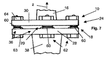
28 基準板(第1の半径方向突出要素)
30 測定板(第2の半径方向突出要素)
32 ロッド(振れ部分)
34 渦電流センサ・システム
36 圧電抵抗センサ・システム
38 円錐(円錐形固定具)
40 締付け収容部
42 ミル加工特徴部分
44 第1の渦電流変位センサ
45 第2の渦電流変位センサ
46 第3の渦電流変位センサ
47 第4の渦電流変位センサ
50 DiaForce(登録商標)センサ(非晶質ダイヤモンド状炭素の圧電抵抗層)
52 ひずみゲージ
54 ロボット
60 リング・センサ
62 ねじ留め具
63 ボルト
64 ナット
z 軸方向
x,y 横方向
Claims (18)
- 1本のツール(12)と、
前記1本のツール(12)に設けられ、軸方向力を検出するための第1の感知装置(18)と、
横方向の力を検出するための第2の感知装置(20)と、
第1の半径方向突出要素(28)と、
前記第1の半径方向突出要素(28)に対向している第2の半径方向突出要素(30)と、
を備え、
前記第2の感知装置(20)が、第1の半径方向突出要素(28)と第2の半径方向突出要素(30)との間に挟まれ、前記1本のロッドの延長上に設けられた1つの振れ部分(32)を有し、
前記振れ部分(32)に軸方向力を検出するためのひずみゲージセンサ(52)が設けられていることを特徴とするツール・ホルダ(10)。 - 前記第1の感知装置(18)が圧電抵抗層(50)を有し、
前記圧電抵抗層(50)は、前記軸方向力を測定するために軸方向と交差する平面内に延在している、請求項1に記載のツール・ホルダ。 - 前記圧電抵抗層(50)が非晶質ダイヤモンド状炭素膜を有する、請求項2に記載のツール・ホルダ。
- 前記第2の感知装置(20)が、前記ツール・ホルダ(10)および/または前記ツールの横方向の機械的逸脱または振れを検出するように形成されている、請求項1〜3のいずれか1項に記載のツール・ホルダ。
- 少なくとも中間部分(24)が、横方向(x,y)のうちのいずれかの横方向の剛性より実質的に大きい軸方向(z)の軸方向剛性を有する、請求項1〜4のいずれか1項に記載のツール・ホルダ。
- 第1の半径方向突出要素(28)及び第2の半径方向突出要素(30)は、前記振れ部分(32)より高い横方向剛性を有する、請求項1〜5のいずれか1項に記載のツール・ホルダ。
- 前記第1の半径方向突出要素及び前記第2の半径方向突出要素(28,30)の少なくとも一方が、円盤要素または板要素である、請求項6に記載のツール・ホルダ。
- 前記第1の半径方向突出要素及び第2の半径方向突出要素が、互いに平行でかつ非荷重状態で軸方向に垂直に配列された板(28,30)として設計されている、請求項7に記載のツール・ホルダ。
- 前記振れ部分がロッド(32)を有し、
前記ロッド(32)は、前記軸方向(z)に延在しかつ前記ツール・ホルダ(10)の残りの部分に比してきわめて小さい剛性および/または直径を有する、請求項6〜8のいずれか1項に記載のツール・ホルダ。 - 前記ロッド(32)が、前記第1の半径方向突出要素及び第2の半径方向突出要素(28,30)を互いに離間させるように相互接続する、請求項9及び請求項6〜8のいずれか1項に記載のツール・ホルダ。
- 前記第2の感知装置(20)が、さらに、前記第1の半径方向突出要素(28)の半径方向突出部と、これに対応する前記第2の半径方向突出要素(30)の半径方向突出部分との間の距離の変化を検出するための少なくとも1つの変位センサ(44〜47)を有する、請求項6〜10のいずれか1項に記載のツール・ホルダ。
- 前記第2の感知装置(20)が、円周方向に互いに離間された少なくとも3つの異なる点において前記第1の半径方向突出要素及び第2の半径方向突出要素(28,30)の半径方向突出部分の間の距離の変化を検出するために、円周方向に互いに離間された少なくとも3つの変位センサ(44〜47)を有する、請求項11に記載のツール・ホルダ。
- 前記少なくとも1つの変位センサが、
渦電流センサ(44〜47)と、
ひずみゲージと、
容量性距離センサと、
誘導性距離センサ、
光学距離または変位センサとを含む、請求項11または12のいずれか1項に記載のツール・ホルダ。 - 前記第2の感知装置(20)がさらに複数の力センサ(60)を有し、
前記複数の力センサ(60)は、前記第1の半径方向突出要素(28)の半径方向突出部分とこれに対応する前記第2の半径方向突出要素(30)の半径方向突出部分との間の押す力または引っ張る力の変化をそれぞれ検出する、請求項6〜13のいずれか1項に記載のツール・ホルダ。 - 前記複数の力センサ(1〜4)が、圧電抵抗層(60)の円周方向に離間された少なくとも3つの領域を有する、請求項14に記載のツール・ホルダ。
- 前記ツール・ホルダ(10)を機械装置(54)に接続するためのフランジ接続部分(22)を有し、前記フランジ接続部分(22)が、円周方向に互いに離間された複数のスルーホールを有するフランジを有する、請求項1〜15のいずれか1項に記載のツール・ホルダ。
- 加工力を測定し、前記測定した加工力に応じて段階的シート成形段階を制御するために請求項1〜16のいずれか1項に記載のツール・ホルダ(10)を使用する、段階的シート成形方法。
- 機械装置(54)からツール(12)に金属加工力を伝達するように形成され、
前記第1の半径方向突出要素及び第2の半径方向突出要素(28,30)の偏心部分の間で変位または押す力/引っ張る力をそれぞれ測定するために円周方向に離間された複数の変位センサ(44〜47)または力センサ(60)と、
を有する請求項1〜16のいずれか1項に記載の前記ツール・ホルダ(10)の前記第2の感知装置(20)として使用するための力感知装置。
Applications Claiming Priority (3)
| Application Number | Priority Date | Filing Date | Title |
|---|---|---|---|
| EP07118993.0 | 2007-10-22 | ||
| EP07118993A EP2052810B1 (en) | 2007-10-22 | 2007-10-22 | Tool holder and incremental sheet forming method using the same |
| PCT/EP2008/064091 WO2009053323A2 (en) | 2007-10-22 | 2008-10-20 | Tool holder and incremental sheet forming method using the same |
Publications (2)
| Publication Number | Publication Date |
|---|---|
| JP2011500331A JP2011500331A (ja) | 2011-01-06 |
| JP5355579B2 true JP5355579B2 (ja) | 2013-11-27 |
Family
ID=39011963
Family Applications (1)
| Application Number | Title | Priority Date | Filing Date |
|---|---|---|---|
| JP2010530413A Expired - Fee Related JP5355579B2 (ja) | 2007-10-22 | 2008-10-20 | ツール・ホルダおよびツール・ホルダを使用する段階的シート成形方法 |
Country Status (6)
| Country | Link |
|---|---|
| EP (1) | EP2052810B1 (ja) |
| JP (1) | JP5355579B2 (ja) |
| AT (1) | ATE490051T1 (ja) |
| DE (1) | DE602007010947D1 (ja) |
| ES (1) | ES2356936T3 (ja) |
| WO (1) | WO2009053323A2 (ja) |
Families Citing this family (14)
| Publication number | Priority date | Publication date | Assignee | Title |
|---|---|---|---|---|
| PT105888B (pt) * | 2011-09-15 | 2013-09-12 | Univ Aveiro | Máquina para estampagem incremental de chapa |
| CN103743502B (zh) * | 2013-12-11 | 2016-04-13 | 西安交通大学 | 一种压阻式旋转二分量铣削力传感器 |
| DE102013226448A1 (de) | 2013-12-18 | 2015-06-18 | Etel S.A. | Positioniereinrichtung |
| MY173106A (en) * | 2014-07-18 | 2019-12-26 | Ukm Tech Sdn Bhd | Integrated rotating dynamometer for milling or drilling process |
| EP3184237B1 (en) * | 2015-12-22 | 2020-05-27 | Sandvik Intellectual Property AB | Sensor module and tool holder for a cutting tool |
| US10363646B2 (en) | 2016-05-05 | 2019-07-30 | Caterpillar Inc. | Manufacturing fixture system and associated process having a rest pad force sensor with closed loop feedback |
| JP6701570B2 (ja) * | 2016-06-06 | 2020-05-27 | 日産自動車株式会社 | 逐次成形方法及び逐次成形装置 |
| CN108405696B (zh) * | 2018-02-06 | 2020-04-03 | 王玉国 | 一种智能旋压系统及旋压加工方法 |
| JP6885529B1 (ja) * | 2019-09-09 | 2021-06-16 | 住友電気工業株式会社 | 切削工具、切削システム、処理方法および処理プログラム |
| JP6950856B2 (ja) * | 2019-09-09 | 2021-10-13 | 住友電気工業株式会社 | 切削工具、切削システム、処理方法および処理プログラム |
| JP7261984B2 (ja) * | 2019-09-18 | 2023-04-21 | パナソニックIpマネジメント株式会社 | 打ち抜き装置 |
| EP4073767A4 (en) | 2019-12-10 | 2024-01-31 | Barnes Group Inc | WIRELESS SENSOR WITH BEACON TECHNOLOGY |
| CN113634643B (zh) * | 2021-07-30 | 2023-08-08 | 西安理工大学 | 一种薄壁管端偏心振动渐进成形装置 |
| TWI812107B (zh) * | 2022-03-24 | 2023-08-11 | 國立中正大學 | 刀把感測器配置 |
Family Cites Families (14)
| Publication number | Priority date | Publication date | Assignee | Title |
|---|---|---|---|---|
| US4733049A (en) * | 1963-01-11 | 1988-03-22 | Lemelson Jerome H | Machining method and apparatus |
| US3602090A (en) | 1970-02-27 | 1971-08-31 | Boeing Co | Milling machine control system and milling force sensor therefor |
| JPS5915818B2 (ja) * | 1975-10-17 | 1984-04-11 | 東レ株式会社 | 包装用材料 |
| DE2906892A1 (de) | 1979-02-22 | 1980-09-11 | Kurt Manfred Dipl Phys Tischer | Anordnung fuer eine werkzeugueberwachung und -bruchkontrolle mit hilfe von piezoxiden |
| JPS5793223A (en) * | 1980-11-29 | 1982-06-10 | Matsushita Electric Works Ltd | Device for measuring machining component of force for spinning and flow forming |
| JPS58205830A (ja) * | 1982-05-26 | 1983-11-30 | Hitachi Ltd | 薄型フオ−スセンサ |
| JPS5973920A (ja) | 1982-10-20 | 1984-04-26 | Mitsubishi Heavy Ind Ltd | シ−ト冷却装置 |
| DE3402301A1 (de) * | 1984-01-24 | 1985-08-01 | Fritz Prof. Dr.-Ing. 5450 Neuwied Fischer | Vorrichtung und verfahren zum drueckwalzen |
| JPS6128835A (ja) * | 1984-07-20 | 1986-02-08 | Nippon Telegr & Teleph Corp <Ntt> | 多分力検出器 |
| US4671147A (en) | 1985-05-30 | 1987-06-09 | General Electric Company | Instrumented tool holder |
| FR2617266B1 (fr) | 1987-06-23 | 1989-12-22 | Caillau Ets | Collier de serrage |
| JPH10296345A (ja) * | 1997-04-25 | 1998-11-10 | Hitachi Ltd | 板材の連続逐次張り出し成形方法およびその装置 |
| JP4175891B2 (ja) * | 2001-01-08 | 2008-11-05 | フラウンホーファー−ゲゼルシャフト ツル フェルデルング デル アンゲヴァンテン フォルシュング エー ファウ | ピエゾ抵抗特性を有するアモルファス炭素層を使用した機械的要素の特性値を状態測定するセンサ |
| WO2006110962A2 (en) | 2005-04-22 | 2006-10-26 | K.U.Leuven Research And Development | Asymmetric incremental sheet forming system |
-
2007
- 2007-10-22 AT AT07118993T patent/ATE490051T1/de not_active IP Right Cessation
- 2007-10-22 DE DE602007010947T patent/DE602007010947D1/de active Active
- 2007-10-22 ES ES07118993T patent/ES2356936T3/es active Active
- 2007-10-22 EP EP07118993A patent/EP2052810B1/en active Active
-
2008
- 2008-10-20 WO PCT/EP2008/064091 patent/WO2009053323A2/en active Application Filing
- 2008-10-20 JP JP2010530413A patent/JP5355579B2/ja not_active Expired - Fee Related
Also Published As
| Publication number | Publication date |
|---|---|
| WO2009053323A3 (en) | 2009-08-06 |
| JP2011500331A (ja) | 2011-01-06 |
| WO2009053323A2 (en) | 2009-04-30 |
| EP2052810A1 (en) | 2009-04-29 |
| DE602007010947D1 (de) | 2011-01-13 |
| EP2052810B1 (en) | 2010-12-01 |
| ATE490051T1 (de) | 2010-12-15 |
| ES2356936T3 (es) | 2011-04-14 |
Similar Documents
| Publication | Publication Date | Title |
|---|---|---|
| JP5355579B2 (ja) | ツール・ホルダおよびツール・ホルダを使用する段階的シート成形方法 | |
| KR102080426B1 (ko) | 4개 미만의 빔 표면 상에 계측기기를 갖는 힘/토크 센서 | |
| JP4909104B2 (ja) | 力覚センサ | |
| Yaldız et al. | A dynamometer design for measurement the cutting forces on turning | |
| Korkut | A dynamometer design and its construction for milling operation | |
| US10078026B2 (en) | Multi-component force-torque sensing device with reduced cross-talk for twist-compression testing machine | |
| US8776616B2 (en) | Multiaxial force-torque sensors | |
| US20180264614A1 (en) | Linear guiding device for a feed axis of a machine tool | |
| Yaldız et al. | Design, development and testing of a turning dynamometer for cutting force measurement | |
| Denkena et al. | Enabling an industrial robot for metal cutting operations | |
| US4924713A (en) | Transducer to detect force which is applied to machine tool when machining workpiece and its attaching structure | |
| Denkena et al. | Design and analysis of a prototypical sensory Z-slide for machine tools | |
| Parida et al. | Design and development of fixture and force measuring system for friction stir welding process using strain gauges | |
| Rizal et al. | Design and construction of a strain gauge-based dynamometer for a 3-axis cutting force measurement in turning process | |
| Denkena et al. | Detection of tool deflection in milling by a sensory axis slide for machine tools | |
| Subasi et al. | A novel triaxial optoelectronic based dynamometer for machining processes | |
| JP4877665B2 (ja) | 3軸力覚センサ | |
| Mohanraj et al. | Design, development, calibration, and testing of indigenously developed strain gauge based dynamometer for cutting force measurement in the milling process | |
| Denkena et al. | Sensory workpieces for process monitoring–an approach | |
| Rezvani et al. | Development of a Vise with built-in Piezoelectric and Strain Gauge Sensors for clamping and cutting force measurements | |
| JPH05288216A (ja) | 力検出手段付き直線運動用案内装置 | |
| Denkena et al. | Process monitoring with a force sensitive axis-slide for machine tools | |
| Saglam et al. | Three-component, strain gage based milling dynamometer design and manufacturing | |
| CN110281078B (zh) | 一种镗刀片尖端多参数传感器 | |
| JP2006300908A (ja) | 力変換器 |
Legal Events
| Date | Code | Title | Description |
|---|---|---|---|
| A621 | Written request for application examination |
Free format text: JAPANESE INTERMEDIATE CODE: A621 Effective date: 20111011 |
|
| A977 | Report on retrieval |
Free format text: JAPANESE INTERMEDIATE CODE: A971007 Effective date: 20130110 |
|
| A131 | Notification of reasons for refusal |
Free format text: JAPANESE INTERMEDIATE CODE: A131 Effective date: 20130122 |
|
| A521 | Request for written amendment filed |
Free format text: JAPANESE INTERMEDIATE CODE: A523 Effective date: 20130412 |
|
| TRDD | Decision of grant or rejection written | ||
| A01 | Written decision to grant a patent or to grant a registration (utility model) |
Free format text: JAPANESE INTERMEDIATE CODE: A01 Effective date: 20130806 |
|
| A61 | First payment of annual fees (during grant procedure) |
Free format text: JAPANESE INTERMEDIATE CODE: A61 Effective date: 20130827 |
|
| R150 | Certificate of patent or registration of utility model |
Free format text: JAPANESE INTERMEDIATE CODE: R150 |
|
| R250 | Receipt of annual fees |
Free format text: JAPANESE INTERMEDIATE CODE: R250 |
|
| S111 | Request for change of ownership or part of ownership |
Free format text: JAPANESE INTERMEDIATE CODE: R313117 |
|
| S531 | Written request for registration of change of domicile |
Free format text: JAPANESE INTERMEDIATE CODE: R313531 |
|
| S533 | Written request for registration of change of name |
Free format text: JAPANESE INTERMEDIATE CODE: R313533 |
|
| R350 | Written notification of registration of transfer |
Free format text: JAPANESE INTERMEDIATE CODE: R350 |
|
| R250 | Receipt of annual fees |
Free format text: JAPANESE INTERMEDIATE CODE: R250 |
|
| LAPS | Cancellation because of no payment of annual fees |