US4924713A - Transducer to detect force which is applied to machine tool when machining workpiece and its attaching structure - Google Patents
Transducer to detect force which is applied to machine tool when machining workpiece and its attaching structure Download PDFInfo
- Publication number
- US4924713A US4924713A US07/316,968 US31696889A US4924713A US 4924713 A US4924713 A US 4924713A US 31696889 A US31696889 A US 31696889A US 4924713 A US4924713 A US 4924713A
- Authority
- US
- United States
- Prior art keywords
- transducer
- load
- cutting
- transducers
- piezoelectric sensor
- Prior art date
- Legal status (The legal status is an assumption and is not a legal conclusion. Google has not performed a legal analysis and makes no representation as to the accuracy of the status listed.)
- Expired - Fee Related
Links
Images


Classifications
-
- B—PERFORMING OPERATIONS; TRANSPORTING
- B23—MACHINE TOOLS; METAL-WORKING NOT OTHERWISE PROVIDED FOR
- B23Q—DETAILS, COMPONENTS, OR ACCESSORIES FOR MACHINE TOOLS, e.g. ARRANGEMENTS FOR COPYING OR CONTROLLING; MACHINE TOOLS IN GENERAL CHARACTERISED BY THE CONSTRUCTION OF PARTICULAR DETAILS OR COMPONENTS; COMBINATIONS OR ASSOCIATIONS OF METAL-WORKING MACHINES, NOT DIRECTED TO A PARTICULAR RESULT
- B23Q17/00—Arrangements for observing, indicating or measuring on machine tools
- B23Q17/09—Arrangements for observing, indicating or measuring on machine tools for indicating or measuring cutting pressure or for determining cutting-tool condition, e.g. cutting ability, load on tool
- B23Q17/0952—Arrangements for observing, indicating or measuring on machine tools for indicating or measuring cutting pressure or for determining cutting-tool condition, e.g. cutting ability, load on tool during machining
- B23Q17/0966—Arrangements for observing, indicating or measuring on machine tools for indicating or measuring cutting pressure or for determining cutting-tool condition, e.g. cutting ability, load on tool during machining by measuring a force on parts of the machine other than a motor
Definitions
- the present invention relates to a transducer to detect a cutting force or cutting resistance which is applied to a machine tool when machining a workpiece and, more particularly, to a transducer to detect a cutting force or cutting resistance by using a piezoelectric sensor and to attaching structure which attaches such a transducer to a machine tool.
- the detector is expensive and the rigidity of the detector itself is low, so that when a large force is applied to the detector, it is easily broken.
- the strain measuring method or the motor load current measuring method when measuring a small cutting force or cutting resistance of a small-diameter drill, a tap, or the like, since the detection sensitivity is so low the detector is influenced by noise or the like. Thus, it is difficult to accurately measure the cutting force or cutting resistance. Such a problem is a large obstacle in carrying out the automatic operation of the machine tool.
- Another object of the invention is to provide a transducer which can accurately detect even a small cutting force and cutting resistance by exhibiting a high detection sensitivity and to also provide an attaching structure for attaching such a transducer to a machine tool.
- Still another object of the invention is to provide a transducer for detecting a cutting force and cutting resistance by using a piezoelectric sensor and to also provide an attaching structure for attaching such a transducer to a machine tool.
- Still another object of the invention is to provide a transducer for use in a machine tool in which an internal measurement in an automatic operation can be properly executed and to also provide an attaching structure for attaching such a transducer to a machine tool.
- Still another object of the invention is to provide a transducer which is integrally assembled in a tool holder of a machine tool so that a load which is applied to a cutting tool can be directly and accurately measured.
- Still another object of the invention is to provide a transducer having a circuit which can accurately detect a cutting load and cutting resistance without being influenced by the drift of a piezoelectric sensor.
- a tranducer to detect cutting force or a cutting resistance of a machine tool has a piezoelectric sensor of a film sheet type in which electrode layers are formed on both sides of a piezoelectric material layer and has a structure in which a through hole which accommodates a feed screw shaft or the like of the machine tool is formed at the center of the piezoelectric sensor.
- Such a transducer is attached to the nut portion of the feed screw shaft to move a work table or a tool table in a machine tool or to the bearing portion of the feedscrew shaft and measures the cutting force and cutting resistance during a cutting operation.
- the transducer of the present invention uses a film sheet type piezoelectric sensor, it is not damaged even if a large cutting force or a large cutting resistance is applied to the sensor.
- the film thickness of the piezoelectric sensor is thin, even if a cutting force or cutting resistance is applied to the sensor, the deformation of the sensor itself is extremely small and does not adversely influence the detection accuracy.
- the sensitivity of the transducer can be easily raised by increasing the area of the piezoelectric sensor. By enlarging the area of the piezoelectric sensor, the load per unit area is reduced and the rigidity can be further increased.
- the detection sensitivity is high, a wide measurement range from 1 kgf to 1000 kgf is provided. Even in the case of a small diameter drill or tap generating a small cutting force and cutting resistance, the cutting force and cutting resistance can also be accurately measured.
- the transducer of the invention may be provided integrally with the tool holder. That is, an adapter to fix a cutting tool such as drill, tap, or the like is attached to the tool holder which can be freely attached to or detached from the main shaft of the machine tool. A film sheet type piezoelectric sensor is attached to the adapter so as to be subjected to a cutting load in the axial direction.
- the piezoelectric sensor may be attached to the bearing portion of the adapter in a state in which the sensor is sandwiched between a pair of thrust bearings to which a load in the axial direction is applied. Further, there is provided a rotation retaining member to stop the rotation of the thrust bearing on the side where the transducer is attached.
- the piezoelectric sensor may be divided into four parts in the circumferential direction of the shaft and detects the loads acting along X and Y axes which cross perpendicularly at the shaft by allowing the differences between the detection signals of the divided detecting parts which are symmetrical with respect to the center of the shaft to be calculated.
- the signal from the piezoelectric sensor which is used in the transducer of the present invention is converted into a voltage signal by a charge amplifier and is output.
- a drift occurs in which the output voltage of the charge amplifier changes with a lapse in time.
- two transducers are provided in the cutting load detecting mechanism.
- the cutting load detecting mechanism simultaneously reduces the cutting load which is applied to the piezoelectric sensor of the other transducer.
- the detection outputs of the two transducers are respectively converted into the voltage signals by the charge amplifiers. After the output of one of the charge amplifiers is inverted, the inverted output is added to the output of the other charge amplifier, thereby eliminating the drift.
- FIG. 1 is a cross-sectional view of an embodiment of a transducer according to the present invention
- FIG. 2 is a partially cut away plan view of the transducer of FIG. 1;
- FIG. 3 is a schematic diagram of an NC lathe
- FIG. 4 is a schematic diagram of a vertical type machining center
- FIG. 5 is an exploded assembly diagram of a ball screw mechanism in the machining center
- FIG. 6 is a sectional view of a first embodiment of attaching structure according to the invention.
- FIG. 7 is a sectional view of a second embodiment of attaching structure according to the invention.
- FIG. 8 is an enlarged view of the bearing portion shown in FIG. 7;
- FIG. 9 is a diagram of attaching structure of the present invention in which a transducer is assembled integrally with a supporting bearing;
- FIG. 10 is a partial sectional view of a transducer integrally assembled with a tool holder according to the invention.
- FIG. 11 is an enlarged view of an attaching portion of the transducer in FIG. 10;
- FIG. 12 is a cross-sectional view of another transducer structure which can be attached to the tool holder in FIG. 10;
- FIG. 13 is a circuit diagram of a transducer circuit using a piezoelectric sensor and a charge amplifier
- FIG. 14 is a signal waveform diagram showing a drift of an output voltage which is caused in the transducer circuit of FIG. 13;
- FIG. 15 is a circuit diagram of a transducer circuit of the invention to prevent the drift
- FIG. 16 is a sectional view of a load detecting mechanism to prevent the drift
- FIG. 17 is a cross sectional view of a nut portion in FIG. 16;
- FIG. 18 is a sectional view of another embodiment of a load detecting mechanism to prevent the drift.
- FIGS. 19A, 19B, 19C, and 19D are signal waveform diagrams showing the operation of the circuit in FIG. 16.
- reference numeral 10 denotes a transducer to detect cutting force or a cutting resistance.
- the transducer 10 has a piezoelectric material layer 12 comprising a piezoelectric material at the center thereof and electrode layers 14-1 and 14-2 on both sides of the piezoelectric material layer 12. Lead wires 15-1 and 15-2 are led out from the electrode layers 14-1 and 14-2. Insulative sheets 16-1 and 16-2 are fixed to the outsides of the electrode layers 14-1 and 14-2 with an adhesive agent or the like.
- a film sheet type of piezoelectric sensor is formed by the piezoelectric material layer 12 and electrode layers 14-1 and 14-2. Practically speaking, it is possible to use high molecular piezoelectric material, for instance, PVDF which is known as a piezoelectric film.
- the piezoelectric device of the film type has a thickness of about 0.2 mm. Even if the Young's modulus is small, deformation when the device is subjected to a load is extremely small. Therefore, as will be clearly understood by the description hereinafter, even when the piezoelectric device is directly assembled in a feed screw mechanism of a machine tool, no decrease in the detecting accuracy occurs due to deformation of the piezoelectric device. Further, since a piezoelectric constant (amount of charge generated per unit force) of the piezoelectric device remains constant irrespective of the area to which a force is applied, by enlarging the area, the load per unit area can be reduced and the rigidity can be increased without reducing the sensitivity.
- a through hole 18 for allowing a feed screw shaft or the like of a machine tool to extend therethrough is formed at the center of the transducer 10.
- bolt through holes 20 to attach and fix the transducer 10 are formed.
- the number of bolt through holes 20 can be provided as necessary. On the contrary, if no bolt is used, there is no need to form through holes 20.
- a force can be measured over a wide range from 1 kgf to 1000 kgf and a resolution on the order of about 100 gf can be realized.
- the motions to cut a workpiece are executed in two directions along X and Y axes as shown by arrows.
- the motions are executed in three directions along X, Y, and Z axes.
- all of the motions in the directions along the X, Y, and Z axes to cut a workpiece are obtained by transforming the rotation of a pulse motor into rectilinear motions with a ball screw mechanism.
- the motion in the direction along the Y axis of a saddle 30 which is mounted on a bed 22 so as to be movable in the Y-axis direction is obtained in the following manner.
- a feed screw shaft 26-1 is rotated by a pulse motor 24-1 attached to the bed 22 and the rectilinear motion of a feed nut 28-1 which is threadingly engaged with the feed screw shaft 26-1 is transferred to the saddle 30.
- the motion in the direction along the X axis of a work table (not shown) mounted on the saddle 30 is derived in the following manner.
- a feed screw shaft 26-2 is rotated by a pulse motor 24-2 attached to the saddle 30 and the rectilinear motion of a feed nut 28-2 which is threadingly engaged with the feed screw shaft 26-2 is transferred to the work table.
- a feed screw shaft 26-3 is rotated by a pulse motor 24-3 attached to the column 32 and the rectilinear motion of a feed nut 28-3 which is threadingly engaged with the feed screw shaft 26-3 is transferred to the main shaft head 34, thereby moving the head 34 in the Z-axis direction.
- a component force F 1 in the axial direction upon machining a workpiece which is applied to the feed screw shafts 26-1 to 26 3 is the sum of a cutting force F 2 in each direction and a frictional resistance F 3 on the slide surface.
- the transducer 10 of the invention shown in FIGS. 1 and 2 is attached to the machine tool so as to measure the component force F 1 in the axial direction of the feed screw shaft in equation (1).
- the cutting force F 2 in equation (1) can be separately measured experimentally, there is a difficult problem in the case where the transducer 10 is assembled to an actual machine and the force is measured. Therefore, in the invention, the force F 1 which is the sum of the frictional resistance F 3 and the cutting force F 2 is measured by the transducer 10.
- the frictional resistance F 3 is also increased or decreased in proportion to the cutting force F 2 , even if the frictional resistance F 3 is included, no problem occurs when the sum of the cutting force F 2 and the frictional resistance F 3 is measured as the substantial cutting force. Further, since the frictional force F 3 is fairly smaller than the cutting force F 2 , no practical problem occurs.
- FIG. 6 is an explanatory diagram showing the first embodiment of an attaching structure of the transducer according to the invention.
- reference numeral 26 denotes a feed screw shaft which is rotated by a pulse motor.
- the left side of the feed screw shaft 26 is rotatably supported by a ball screw support including a pair of supporting bearings 36-1 and 36 2 which can simultaneously receive both a radial load and a thrust load.
- An output shaft of the pulse motor is coupled to the end portion of the feed screw shaft 26 located outside of the supporting bearings 36-1 and 36-2.
- the axial end on the right side of the feed screw shaft 26 is rotatably supported by a ball bearing 36-3.
- a feed nut 28 is threadingly engaged with the feed screw shaft 26.
- the transducer 10 of the invention shown in FIGS. 1 and 2 is attached to the feed nut 28 which is threadingly engaged with the feed screw shaft 26. That is, the doughnut shaped transducer 10 shown in FIGS. 1 and 2 is attached to the left end surface of the feed nut 28.
- a coupling portion 40 which is coupled with the work table or machining table is fitted to the outside of the transducer 10, thereby fastening and fixing the transducer 10 to the feed nut 28 with bolts.
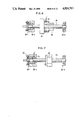
- FIG. 7 is a sectional view of the second embodiment of a transducer attaching structure of the invention.
- the second embodiment is characterized in that the transducer is attached to a ball screw supporting bearing of the feed screw shaft.
- the feed screw shaft 26 which is threadingly engaged with the feed nut 28 coupled with the work table or tool table is mounted. in a manner in which the axial left end is rotatably supported by the pair of supporting bearings 36-1 and 36-2 assembled into a bearing portion 42 and the axial right end is rotatably supported by the ball bearing 36-3.
- the transducer 10 is attached to the ball screw supporting bearing portion 42 into which the supporting bearings 36-1 and 36-2 are assembled.
- the transducer 10 is assembled between the supporting bearing 36-2 and a surface 50 defining a bearing hole 48.
- the transducer 10 is assembled between an outer ring 46 of the supporting bearing 36-2 and the surface 50 defining the bearing hole 48 in a state in which the transducer is sandwiched by a pair of spacer rings 48-1 and 48-2.
- An outer ring 52 of the supporting bearing 36-1 assembled to the outside of the bearing hole 48 is fixed by fastening a metal fitting 54 in the bearing portion with a bolt.
- the transducer 10 is fastened and fixed under a predetermined load.
- each of the spacer rings 48-1 and 48-2 between which the transducer 10 is sandwiched has an L-shaped cross section.
- 0-rings 56 seal the transducer 10 and are interposed between the slide surfaces on the inside and outside of the spacer rings.
- the cutting resistance from the work table or the cutting force from the tool table generated during a cutting operation acts in the axial direction of the feed screw shaft 26 due to the movement in the lateral direction of the feed nut 28 under the rotation of the feed screw shaft 26.
- Such resistance or force is applied to the transducer 10 sandwiched between the spacer rings 48-1 and 48-2 through the outer ring 46 of the supporting bearing 36-2 provided in the bearing portion 42.
- FIG. 9 is a cross-sectional view of another assembling structure in which the transducer 10 is assembled in the bearing portion 42 of the feed screw shaft 26 shown in FIGS. 7 and 8.
- FIG. 9 is designed so that the transducer 10 can be attached without changing the bearing hole 48.
- the right end of the outer ring 46 of the supporting bearing 36-2 is cut out to form a transducer enclosing portion 58.
- the transducer 10 is assembled in the enclosing portion 58 and an L-shaped spacer ring 60 is fixed to the transducer 10 from outside the outer ring 46.
- the 0-rings 56 seal the transducer 10 and are provided on the contact surfaces on the inside and outside of the spacer ring 60.
- the transducer can be also similarly assembled to the feed nut or supporting bearing of the feed screw mechanism of the main shaft system.
- FIG. 10 is a partial sectional view of a transducer integrally assembled with a tool holder.
- reference numeral 62 denotes a tool holder.
- a tapered shaft portion 64 is formed on the main shaft attached side of the tool holder.
- a flange 68 having a flange groove 66 is formed on the front of the tool holder.
- a tool attaching hole 70 shown by a broken line extends in the axial direction from the center of the lower edge surface of the flange 68.
- the tool holder 62 has dimensions and a shape based on, for instance, MAS standards or the like and can be attached to and detached from the main shafts of all of the machine tools as a standard article.
- an adapter 72 Adjacent the tool holder 62 is an adapter 72 for securing therein the transducer which detects the cutting load.
- an attaching shaft 74 adapted to be inserted into the tool attaching hole 70 of the tool holder 62 is integrally formed.
- a chuck 78 to secure a cutting tool for instance, a drill bit 76, is fixed to the lower portion of the adapter 72.
- the adapter 72 can be formed integrally with the chuck 78, in order to enable the adapter 72 to be used as a standard article for all of the cutting tools, it is desirable to provide a tool attaching member such as the chuck 78 or the like that is detachable from the adapter 72. It is obviously possible to directly attach the cutting tool such as the drill bit 76 or the like to the adapter 72 without providing the chuck 78.
- the adapter 72 has a flange 80 on the drill attaching side and also has a shaft portion 82 having small diameter adjacent the flange 80.
- a bearing portion for securing the transducer 10 therein is formed by the flange 80 and shaft portion 82 of the adapter 72 and. further by the flange 68 of the tool holder 62.
- a pair of thrust bearings 84 and 86 are assembled in the axial direction into the bearing portion 82 between the flange 68 of the tool holder 62 and the flange 80 of the adapter 72.
- the transducer 10 comprising the film sheet type piezoelectric sensor is sandwiched and attached between the thrust bearings 84 and 86 through spacer rings 88 and 90 and, further, through a swasher ring 92.
- a rotation retaining member 94 is attached to the outer peripheries of the spacer rings 88 and 90, between which the transducer 10 is sandwiched and fixed between the thrust bearings 84 and 86 through the swasher ring 92.
- the rotation retaining member 94 restricts the rotation of the spacer rings 88 and 90 and allows the spacer rings 88 and 90 to move freely in the axial direction.
- FIG. 11 is an enlarged view of the transducer attaching portion in FIG. 10.
- the spacer rings 88 and 90 are disposed between the thrust bearings 84 and 86.
- the transducer 10 is sandwiched between the spacer rings 88 and 90 through the swasher ring 92.
- 0-rings 96 and 98 are provided on both sides of the transducer 10 sandwiched between the spacer rings 88 and 90 through the swasher ring 92, thereby sealing the transducer 10.
- the cutting load generated during the cutting operation by the drill bit 76 or the like attached to the tip of the adapter 72 acts in the axial direction of the adapter 72.
- the cutting load is applied to the transducer 10 sandwiched between the flange 80 of the adapter 72 and the flange 68 of the tool holder 62 through the thrust bearings 84 and 86 and, further, through the spacer rings 88 and 90 and swasher ring 92, so that the cutting load can be measured.
- the signal voltage corresponding to the cutting load in the axial direction which is applied from the charge amplifier to the transducer 10 due to the start of the cutting operation is obtained.
- FIG. 12 shows another embodiment of the transducer 10 which is attached to the adaptor 72 in FIG. 10.
- the second embodiment is characterized in that the transducer 10 is divided into four transducers 10-1 to 10-4 around the periphery of the shaft.
- the transducers 10-1 and 10-2 are arranged along the Y axis with respect to the coordinate center and the transducers 10-3 and 10-4 are arranged along the X axis with respect to the coordinate center, respectively.
- the loads acting in the directions of the Y and X axes can be also detected.
- the load in the Z-axis direction can be detected by obtaining the sum or average of the detection signals of the transducers 10-1 to 10-4.
- the load in the Y-axis direction can be detected by calculating the difference between the detection signals of the transducers 10-1 and 10-2.
- the load in the X-axis direction can be detected by calculating the difference between the detection signals of the transducers 10-3 and 10-4.
- FIG. 13 shows a transducer detecting circuit of the invention.
- the transducer 10 has a piezoelectric sensor as shown in FIGS. 1 and 2.
- the charges according to the load which is applied to the piezoelectric sensor are generated between the electrodes by the transducer 10. Therefore, a charge amplifying circuit 100 is provided as an external circuit in order to convert the generated charges corresponding to the load applied to the piezoelectric sensor into the voltage signal.
- a capacitor C is connected to a feedback circuit of an operational amplifier 102. Since an amount q x of generated charges changes in accordance with the load, the piezoelectric sensor of the transducer 10 can be regarded as a variable capacitor C x .
- the generated charge amount q x of the piezoelectric sensor is directly transferred to the feedback capacitor C by an imaginary short operation of the operational amplifier 102, so that an output voltage E 0 which is proportional to the generated charge amount q x of the piezoelectric sensor can be ideally obtained.
- the output voltage E 0 is as follows.
- a reset switch 106 is connected to the feedback circuit of the operational amplifier 102 in parallel with the capacitor C. That is, since a predetermined assembling load has already been applied to the piezoelectric sensor of the transducer 10 in the initial state, prior to detecting the load, the capacitor C is discharged and reset and the output voltage is set to zero.
- the drift occurs in the case where the charges generated between the electrodes of the piezoelectric sensor provided in the transducer 10 are amplified and converted into the voltage signal by the charge amplifying circuit 100, since an input impedance of the charge amplifying circuit 100 cannot be set to be infinite, and thus, the charges generated by the piezoelectric sensor leak through the input impedance the output fluctuates.
- FIG. 15 shows a charge amplifying circuit of the present invention to solve the problem associated with the drift which occurs when a constant load is applied to the transducer.
- the charge amplifying circuit uses a load detecting mechanism having two transducers as shown in FIG. 16.
- reference numerals 10-5 and 10-6 denote transducers each having the film sheet type piezoelectric sensor shown in FIGS. 1 and 2.
- the transducers 10-5 and 10-6 are assembled to a load detecting mechanism shown in FIG. 16.
- the cutting load is applied to the transducer 10-5 in such a direction as to increase the assembly load.
- the cutting load is applied to the transducer 10-6 in such a direction as to reduce the assembly load.
- Outputs of the transducers 10-5 and 10-6 are input to charge amplifying circuits 100-1 and 100-2.
- the charge amplifying circuits 100-1 and 100-2 have operational amplifiers 102-1 and 102-2.
- Capacitors C 1 and C 2 are connected to the feedback circuits of the operational amplifiers 102-1 and 102-2.
- reset switches 106-1 and 106-2 to discharge and reset the capacitors C 1 and C 2 are connected in parallel therewith.
- the piezoelectric sensor of the transducer 10-5 Since the piezoelectric sensor of the transducer 10-5 generates the charges in the amount of q x corresponding to the load which is applied, it can be regarded as the variable capacitor C x .
- C 3 denotes a signal cable capacitance between the transducer 10-5 and the charge amplifying circuit 100-1.
- the input voltage E i of the operational amplifier 102-1 is held to almost 0 V.
- the charges generated in the piezoelectric sensor of the transducer 10-5 are all stored in the feedback capacitor C 1 .
- the output voltage E 0 of the charge amplifying circuit 100-1 is unconditionally determined by the ratio of the capacitance of the feedback capacitor C 1 and the amount q x of charges generated by the piezoelectric sensor.
- the principle behind the charge amplifying circuit 100-1 is also similar to that behind the charge amplifying circuit 100-2 provided for the transducer 10-6.
- An output of the charge amplifying circuit 100-1 to convert and amplify the charges generated in the piezoelectric sensor provided in the transducer 10-1 into the voltage signal is input to an adding circuit 108.
- an output of the charge amplifying circuit 100-2 to convert and amplify the charges generated in the piezoelectric sensor provided in the transducer 10-6 is inverted by an inverting circuit 110. Thereafter, the inverted output is input to the adding circuit 108.
- the adding circuit 108 outputs a signal in which the inverted output of the charge amplifying circuit 100-2 has been added to the output of the charge amplifying circuit 100-1.
- FIG. 16 shows a load detecting mechanism having the transducers 10-5 and 10-6 shown in the embodiment of FIG. 15.
- the right end of the feed screw shaft 26 is rotatably supported by the ball bearing 36-3 and the left end is rotatably supported by the pair of supporting bearings 36-1 and 36-2 to which both the radial load and the thrust load are applied.
- An output shaft of a pulse motor (not shown) is coupled with the axial end of the feed screw shaft 26 projecting from the supporting bearings 36-1 and 36-2.
- the feed nut 28 is threadingly engaged with the feed screw shaft 26.
- the transducers 10-5 and 10-6 are arranged at both ends of the feed nut 28.
- the transducers 10-5 and 10-6 are fastened and fixed to the nut member 28 by presser metal fittings 112-1 and 112-2 fastened with bolts.
- FIG. 17 is an enlarged view of the portion of the feed nut 28 attached to the feed screw shaft 26 in FIG. 16.
- the feed nut 28 has a screw hole 114 which is in threaded engagement with the feed screw shaft 26.
- the transducers 10-5 and 10-6 are fitted to the shaft portions on both sides of the feed nut 28.
- the presser metal fittings 112-1 and 112-2 are fitted onto the transducers 10-5 and 10-6 from outside the feed nut, thereby fastening and fixing the transducers to the feed nut 28 by being fastened to the feed nut with bolts.
- the load in the axial direction which is applied to the transducer 10-5 arranged on the right side of the feed nut 28 through the work table or tool table, in correspondence with the cutting load, acts in such a direction as to increase the fastening load on the transducer 10-6.
- such a load in the axial direction contrarily acts to decrease the fastening load on the transducer 10-5 attached on the left side of the feed nut 28.
- the load acts on the piezoelectric sensor of the transducer 10-5 on the left side in such a direction as to increase the fastening load.
- the load in the axial direction acts on the transducer 10-6 on the right side in such a direction as to reduce the fastening load.
- FIG. 18 shows a load detecting mechanism having the transducers 10-5 and 10-6 shown in FIG. 15.
- the transducers 10-5 and 10-6 are assembled into the portions of the supporting bearings 36-1 and 36-2 which rotatably support the feed screw shaft 26 and to which thrust loads are applied. That is, the transducer 10-5 is assembled to the left side of the supporting bearing 36-1 within the bearing hole 48. The transducer 10-6 is assembled to the right side of the supporting bearing 36-2.
- the presser metal fitting 54 is fastened and fixed to the bearing hole 48 from the outside thereof with bolts.
- the pressing forces are transmitted through the side surfaces of the outer rings of the supporting bearings 36-1 and 36-2 to the transducers 10-5 and 10-6. Since the inner ring is fitted onto the side of the feed screw shaft 26 and is rotated, it is disposed so as not to contact the transducers 10-5 and 10-6.
- the right end of the feed screw shaft 26 is rotatably supported by the ball bearing 36-3.
- the feed nut 28 to transform the rotational motion of the feed screw into rectilinear motion is threadingly engaged with the feed screw shaft 26.
- FIG. 19A shows the output voltage of the charge amplifying circuit 100-1 to convert and amplify the charges generated in the transducer 10-5.
- FIG. 19B shows the output voltage of the charge amplifying circuit 100-2 to convert and amplify the charges generated in the transducer 10-6.
- FIGS. 19A and 19B show the cases in which the cutting load is applied to the transducer 10-5 in such a direction as to increase the cutting load and the cutting load is applied to the transducer 10-6 in such a direction as to decrease the cutting load.
- the reset switches 106-1 and 106-2 provided in the charge amplifying circuits 100 1 and 100-2 are turned on until time t 0 at which the cutting operation of the machine tool starts.
- the feedback capacitors C 1 and C 2 are set in the discharge reset state.
- the charges generated by the assembly loads on the transducers 10-5 and 10-6 are discharged and reset, thereby setting the output voltage to 0 V.
- the reset switches 106-1 and 106-2 are turned off at time t 0 to start the cutting operation of the machine tool, the output voltage increases due to the drift occurring with the lapse of time.
- the cutting load in such a direction as to increase the assembly load is applied to the transducer 10-5, so that the output voltage of the charge amplifying circuit 100-1 increases in accordance with the cutting load.
- the cutting load is applied to the transducer 100-2 in such a direction as to decrease the assembly load and the output voltage of the charge amplifying circuit 100-2 decreases in accordance with the cutting load.
- the output voltage of the charge amplifying circuit 100-1 in FIG. 19A is directly input to the adding circuit 108.
- the output voltage of the charge amplifying circuit 100-2 is inverted by the inverting circuit 110 and becomes an inversion signal as shown in FIG. 19C and is issued to the adding circuit 108.
- the adding circuit 108 produces an addition output shown in FIG. 19D in which the output voltage of FIG. 19A and the inverted voltage of FIG. 19C have been added.
- the drift components due to the lapse of time are set off. Further, the output voltage to which the output voltage due to a change in cutting load was added can be obtained. That is, since the charge amplifying circuits 100-1 and 100 2 have the same circuit arrangement, the drift components generated with the lapse of time also coincide. By inverting one of the drift components and adding it to the other, the drift components can be almost completely set off.
- the inverted output of the charge amplifying circuit 100-2 is added to the output of the charge amplifying circuit 100-1.
- the transducers 10-5 and 10-6 are provided for the feed nut of the feed screw mechanism of the work table or the supporting bearing.
- the transducers may be also provided for the feed nut of the feed screw mechanism of the main shaft system or the supporting bearing.
Landscapes
- Engineering & Computer Science (AREA)
- Mechanical Engineering (AREA)
- Force Measurement Appropriate To Specific Purposes (AREA)
Abstract
Description
F.sub.1 =F.sub.2 +F.sub.3 (1)
E.sub.0 =-q.sub.x /C
E.sub.0 =-A·E.sub.i
E.sub.i -E.sub.0 =q.sub.1 /C.sub.1
E.sub.i =(q.sub.x -q.sub.1)/(C.sub.x +C.sub.3)
q.sub.x =q.sub.1 ·{1+(C.sub.x +C.sub.3)/C.sub.1 (1+A)}
E.sub.i =q.sub.1 /C.sub.1 ·1/(1+A)
E.sub.0 =-q.sub.1 /C.sub.1 ·A/(1+A)
q.sub.x =q.sub.1
E.sub.i =0
E.sub.0 =-q.sub.1 /C.sub.1
Claims (5)
Applications Claiming Priority (6)
| Application Number | Priority Date | Filing Date | Title |
|---|---|---|---|
| JP63-59822 | 1988-03-14 | ||
| JP63-59823 | 1988-03-14 | ||
| JP63059823A JPH0769231B2 (en) | 1988-03-14 | 1988-03-14 | Load detection device using piezoelectric sensor |
| JP63059822A JPH0675816B2 (en) | 1988-03-14 | 1988-03-14 | Mounting structure for machine tool detector |
| JP63059824A JPH0665454B2 (en) | 1988-03-14 | 1988-03-14 | Tool mounting adapter with load detector |
| JP63-59824 | 1988-05-06 |
Publications (1)
| Publication Number | Publication Date |
|---|---|
| US4924713A true US4924713A (en) | 1990-05-15 |
Family
ID=27297011
Family Applications (1)
| Application Number | Title | Priority Date | Filing Date |
|---|---|---|---|
| US07/316,968 Expired - Fee Related US4924713A (en) | 1988-03-14 | 1989-02-28 | Transducer to detect force which is applied to machine tool when machining workpiece and its attaching structure |
Country Status (1)
| Country | Link |
|---|---|
| US (1) | US4924713A (en) |
Cited By (21)
| Publication number | Priority date | Publication date | Assignee | Title |
|---|---|---|---|---|
| US5321977A (en) * | 1992-12-31 | 1994-06-21 | International Business Machines Corporation | Integrated tip strain sensor for use in combination with a single axis atomic force microscope |
| US5542304A (en) * | 1993-10-29 | 1996-08-06 | Omron Corporation | Magnetostrictive torque sensor, magnetostrictive torque measuring apparatus, and condition-monitoring apparatus for a cutting tool using the same |
| WO1997047953A1 (en) * | 1996-06-14 | 1997-12-18 | Wittenstein Motion Control Gmbh | Device for detecting and evaluating the motive power acting on a linear drive |
| US5783751A (en) * | 1996-12-31 | 1998-07-21 | Industrial Technology Research Institute | Cutting force sensor in the form of a turret locking screw |
| EP0927645A1 (en) * | 1998-01-05 | 1999-07-07 | MDC Max Dätwyler Bleienbach AG | Device and treatment method of an intaglio printing plate |
| EP0927646A1 (en) * | 1998-01-05 | 1999-07-07 | MDC Max Dätwyler Bleienbach AG | Device and treatment method of an intaglio printing plate |
| US20020117939A1 (en) * | 2001-02-23 | 2002-08-29 | Satoru Kawamoto | Piezoelectric actuator drive circuit and fuel injection system |
| EP1400310A1 (en) * | 2002-09-19 | 2004-03-24 | CLAAS Fertigungstechnik GmbH | method and device for determining depth of penetration |
| WO2007025404A1 (en) * | 2005-08-31 | 2007-03-08 | Kistler Holding Ag | Tool condition monitoring system |
| EP1764186A1 (en) * | 2005-09-14 | 2007-03-21 | Werner Kluft | System for controlling a machining process with axial piezoelectric sensors in the working spindle |
| US20100178848A1 (en) * | 2007-10-15 | 2010-07-15 | Yasuo Tomita | Protecting device for processing tool of machine tool and honing machine |
| US20100232894A1 (en) * | 2009-03-16 | 2010-09-16 | The Boeing Company | Adaptor with Interchangeable Load Sensing Elements |
| US20110203433A1 (en) * | 2010-02-24 | 2011-08-25 | Mag Ias Gmbh | Cutting device for shear-cutting of fibre strands |
| TWI468249B (en) * | 2009-03-13 | 2015-01-11 | Univ Nat Sun Yat Sen | Work table |
| US20150268110A1 (en) * | 2014-03-24 | 2015-09-24 | Goodrich Actuation Systems Sas | Load sensing system |
| US20170052530A1 (en) * | 2013-12-04 | 2017-02-23 | Ceramtec Gmbh | Tool having preventative fracture, breakage, crack and wear detection |
| US9873201B2 (en) | 2013-02-19 | 2018-01-23 | Seiko Epson Corporation | Force detection device, robot, and moving object |
| DE102017101385A1 (en) | 2017-01-25 | 2018-07-26 | Minebea Intec GmbH | Creep adaptation for piezoresistive measuring strips |
| US20190010987A1 (en) * | 2017-07-04 | 2019-01-10 | Buffalo Machinery Company Limited | Detecting Apparatus for Detecting Axial Displacement of Bearing Unit |
| WO2020239378A1 (en) * | 2019-05-28 | 2020-12-03 | Atlas Copco Industrial Technique Ab | Power drill and force transducer for such a drill |
| FR3117052A1 (en) * | 2020-12-03 | 2022-06-10 | Etablissements Georges Renault | Drilling device with means for measuring axial thrust forces. |
Citations (7)
| Publication number | Priority date | Publication date | Assignee | Title |
|---|---|---|---|---|
| US3464503A (en) * | 1968-06-25 | 1969-09-02 | Black & Decker Mfg Co | Measuring device for impact tool |
| US3872285A (en) * | 1974-05-31 | 1975-03-18 | Westinghouse Electric Corp | Control system for sensing the vibration and lateral force on a cutting tool |
| US4499394A (en) * | 1983-10-21 | 1985-02-12 | Koal Jan G | Polymer piezoelectric sensor of animal foot pressure |
| US4577510A (en) * | 1984-09-06 | 1986-03-25 | The United States Of America As Represented By The Secretary Of The Air Force | Dynamic polymer pressure transducer with temperature compensation |
| DE3437246A1 (en) * | 1984-10-11 | 1986-04-17 | Index-Werke Kg Hahn & Tessky, 7300 Esslingen | Sensor for measuring a cutting force component in a machine tool |
| US4741231A (en) * | 1986-04-14 | 1988-05-03 | The Warner & Swasey Company | Tool force sensor and method of making same |
| US4807482A (en) * | 1987-05-18 | 1989-02-28 | Temple University Of The Commonwealth System Of Higher Education | Method and apparatus for measuring stimuli applied to a piezoelectric transducer |
-
1989
- 1989-02-28 US US07/316,968 patent/US4924713A/en not_active Expired - Fee Related
Patent Citations (7)
| Publication number | Priority date | Publication date | Assignee | Title |
|---|---|---|---|---|
| US3464503A (en) * | 1968-06-25 | 1969-09-02 | Black & Decker Mfg Co | Measuring device for impact tool |
| US3872285A (en) * | 1974-05-31 | 1975-03-18 | Westinghouse Electric Corp | Control system for sensing the vibration and lateral force on a cutting tool |
| US4499394A (en) * | 1983-10-21 | 1985-02-12 | Koal Jan G | Polymer piezoelectric sensor of animal foot pressure |
| US4577510A (en) * | 1984-09-06 | 1986-03-25 | The United States Of America As Represented By The Secretary Of The Air Force | Dynamic polymer pressure transducer with temperature compensation |
| DE3437246A1 (en) * | 1984-10-11 | 1986-04-17 | Index-Werke Kg Hahn & Tessky, 7300 Esslingen | Sensor for measuring a cutting force component in a machine tool |
| US4741231A (en) * | 1986-04-14 | 1988-05-03 | The Warner & Swasey Company | Tool force sensor and method of making same |
| US4807482A (en) * | 1987-05-18 | 1989-02-28 | Temple University Of The Commonwealth System Of Higher Education | Method and apparatus for measuring stimuli applied to a piezoelectric transducer |
Cited By (34)
| Publication number | Priority date | Publication date | Assignee | Title |
|---|---|---|---|---|
| US5321977A (en) * | 1992-12-31 | 1994-06-21 | International Business Machines Corporation | Integrated tip strain sensor for use in combination with a single axis atomic force microscope |
| US5345816A (en) * | 1992-12-31 | 1994-09-13 | International Business Machine Corp. | Integrated tip strain sensor for use in combination with a single axis atomic force microscope |
| US5542304A (en) * | 1993-10-29 | 1996-08-06 | Omron Corporation | Magnetostrictive torque sensor, magnetostrictive torque measuring apparatus, and condition-monitoring apparatus for a cutting tool using the same |
| WO1997047953A1 (en) * | 1996-06-14 | 1997-12-18 | Wittenstein Motion Control Gmbh | Device for detecting and evaluating the motive power acting on a linear drive |
| US6189391B1 (en) | 1996-06-14 | 2001-02-20 | Wittenstein Motion Control Gmbh | Linear drive having a device for sensing and evaluating an operational force acting thereon |
| US5783751A (en) * | 1996-12-31 | 1998-07-21 | Industrial Technology Research Institute | Cutting force sensor in the form of a turret locking screw |
| EP0927645A1 (en) * | 1998-01-05 | 1999-07-07 | MDC Max Dätwyler Bleienbach AG | Device and treatment method of an intaglio printing plate |
| EP0927646A1 (en) * | 1998-01-05 | 1999-07-07 | MDC Max Dätwyler Bleienbach AG | Device and treatment method of an intaglio printing plate |
| US20020117939A1 (en) * | 2001-02-23 | 2002-08-29 | Satoru Kawamoto | Piezoelectric actuator drive circuit and fuel injection system |
| US6617755B2 (en) * | 2001-02-23 | 2003-09-09 | Denso Corporation | Piezoelectric actuator drive circuit and fuel injection system |
| EP1400310A1 (en) * | 2002-09-19 | 2004-03-24 | CLAAS Fertigungstechnik GmbH | method and device for determining depth of penetration |
| WO2007025404A1 (en) * | 2005-08-31 | 2007-03-08 | Kistler Holding Ag | Tool condition monitoring system |
| US20100132528A1 (en) * | 2005-08-31 | 2010-06-03 | Kistler Holding Ag | Tool condition monitoring system |
| US8376666B2 (en) | 2005-08-31 | 2013-02-19 | Kistler Holding Ag | Tool condition monitoring system |
| EP1764186A1 (en) * | 2005-09-14 | 2007-03-21 | Werner Kluft | System for controlling a machining process with axial piezoelectric sensors in the working spindle |
| US20070063620A1 (en) * | 2005-09-14 | 2007-03-22 | Werner Kluft | Process monitoring device and method for process monitoring at machine tools |
| US20100178848A1 (en) * | 2007-10-15 | 2010-07-15 | Yasuo Tomita | Protecting device for processing tool of machine tool and honing machine |
| TWI468249B (en) * | 2009-03-13 | 2015-01-11 | Univ Nat Sun Yat Sen | Work table |
| US20100232894A1 (en) * | 2009-03-16 | 2010-09-16 | The Boeing Company | Adaptor with Interchangeable Load Sensing Elements |
| US20110203433A1 (en) * | 2010-02-24 | 2011-08-25 | Mag Ias Gmbh | Cutting device for shear-cutting of fibre strands |
| US8438959B2 (en) * | 2010-02-24 | 2013-05-14 | Mag Ias, Gmbh | Cutting device for shear-cutting of fibre strands |
| US9873201B2 (en) | 2013-02-19 | 2018-01-23 | Seiko Epson Corporation | Force detection device, robot, and moving object |
| US20170052530A1 (en) * | 2013-12-04 | 2017-02-23 | Ceramtec Gmbh | Tool having preventative fracture, breakage, crack and wear detection |
| EP2924304B1 (en) * | 2014-03-24 | 2023-12-13 | Goodrich Actuation Systems SAS | Load sensing system |
| US20150268110A1 (en) * | 2014-03-24 | 2015-09-24 | Goodrich Actuation Systems Sas | Load sensing system |
| US9891122B2 (en) * | 2014-03-24 | 2018-02-13 | Goodrich Actuation Systems Sas | Load sensing system |
| DE102017101385A1 (en) | 2017-01-25 | 2018-07-26 | Minebea Intec GmbH | Creep adaptation for piezoresistive measuring strips |
| DE102017101385B4 (en) | 2017-01-25 | 2023-01-05 | Minebea Intec GmbH | Creep adjustment for piezoresistive gages |
| US10731705B2 (en) * | 2017-07-04 | 2020-08-04 | Buffalo Machinery Company Limited | Detecting apparatus for detecting axial displacement of bearing unit |
| US20190010987A1 (en) * | 2017-07-04 | 2019-01-10 | Buffalo Machinery Company Limited | Detecting Apparatus for Detecting Axial Displacement of Bearing Unit |
| WO2020239378A1 (en) * | 2019-05-28 | 2020-12-03 | Atlas Copco Industrial Technique Ab | Power drill and force transducer for such a drill |
| CN114173971A (en) * | 2019-05-28 | 2022-03-11 | 阿特拉斯·科普柯工业技术公司 | Power drill and force sensor for such a drill |
| CN114173971B (en) * | 2019-05-28 | 2023-09-22 | 阿特拉斯·科普柯工业技术公司 | Power drill and force sensor for such a drill |
| FR3117052A1 (en) * | 2020-12-03 | 2022-06-10 | Etablissements Georges Renault | Drilling device with means for measuring axial thrust forces. |
Similar Documents
| Publication | Publication Date | Title |
|---|---|---|
| US4924713A (en) | Transducer to detect force which is applied to machine tool when machining workpiece and its attaching structure | |
| JP5355579B2 (en) | Tool holder and stepwise sheet forming method using the tool holder | |
| US4369663A (en) | Transducer with six degrees of freedom | |
| CN108620948B (en) | Detection compensation control system for air static pressure main shaft | |
| JP2003329525A (en) | System, method and apparatus for load display | |
| US20230195080A1 (en) | Composite intelligent detection method and cutting apparatus | |
| US5042309A (en) | Apparatus and method for sensing a thrust load applied to a spindle of a machine tool | |
| US5211060A (en) | Bidirectional force sensor | |
| JPH05138481A (en) | Rectilinear guiding device with axial force detecting means | |
| US20200278656A1 (en) | Information processing device and information processing method | |
| JPH04231829A (en) | Intervening type force sensor having pallalelized disk measuring element and integrated amplifier | |
| JPH02303752A (en) | Torque detector for machine tool | |
| US6453751B1 (en) | Device for measuring pulling-in force | |
| JPH01234138A (en) | Detector for machine tool and detector fitting structure | |
| JP2715615B2 (en) | Magnetic bearing control device | |
| JPH03149158A (en) | Torque-thrust-bending force detecting spindle | |
| JP3412208B2 (en) | Tool cutting machine | |
| JPH01233338A (en) | Load detector using piezoelectric sensor | |
| RU2116165C1 (en) | Spindle assembly of metal-cutting machine tool | |
| Sandwell et al. | Development of multi-degrees of freedom optical table dynamometer | |
| KR19980072253A (en) | Waveform Correction System for Precision Machining Using Piezoelectric Microincision Device | |
| Murthy et al. | Design and development of strain gauge based milling tool dynamometer | |
| JPH02116454A (en) | Tool holder for machine tool | |
| JPS62176756A (en) | Polishing device | |
| JPH05143159A (en) | Friction driving mechanism |
Legal Events
| Date | Code | Title | Description |
|---|---|---|---|
| AS | Assignment |
Owner name: ELCO CO., LTD., JAPAN Free format text: ASSIGNMENT OF ASSIGNORS INTEREST.;ASSIGNORS:MACHINO, TOSHIMICHI;ODA, SAIJI;TOUBO, KIHACHIROU;AND OTHERS;REEL/FRAME:005050/0648 Effective date: 19890210 Owner name: TOYAMA-KEN, JAPAN Free format text: ASSIGNMENT OF ASSIGNORS INTEREST.;ASSIGNORS:MACHINO, TOSHIMICHI;ODA, SAIJI;TOUBO, KIHACHIROU;AND OTHERS;REEL/FRAME:005050/0648 Effective date: 19890210 |
|
| FEPP | Fee payment procedure |
Free format text: PAYOR NUMBER ASSIGNED (ORIGINAL EVENT CODE: ASPN); ENTITY STATUS OF PATENT OWNER: LARGE ENTITY |
|
| FPAY | Fee payment |
Year of fee payment: 4 |
|
| FPAY | Fee payment |
Year of fee payment: 8 |
|
| REMI | Maintenance fee reminder mailed | ||
| LAPS | Lapse for failure to pay maintenance fees | ||
| STCH | Information on status: patent discontinuation |
Free format text: PATENT EXPIRED DUE TO NONPAYMENT OF MAINTENANCE FEES UNDER 37 CFR 1.362 |
|
| FP | Lapsed due to failure to pay maintenance fee |
Effective date: 20020515 |