JP5345598B2 - Inspection jig and contact - Google Patents
Inspection jig and contact Download PDFInfo
- Publication number
- JP5345598B2 JP5345598B2 JP2010229524A JP2010229524A JP5345598B2 JP 5345598 B2 JP5345598 B2 JP 5345598B2 JP 2010229524 A JP2010229524 A JP 2010229524A JP 2010229524 A JP2010229524 A JP 2010229524A JP 5345598 B2 JP5345598 B2 JP 5345598B2
- Authority
- JP
- Japan
- Prior art keywords
- contact
- coil spring
- diameter
- electrode
- inspection
- Prior art date
- Legal status (The legal status is an assumption and is not a legal conclusion. Google has not performed a legal analysis and makes no representation as to the accuracy of the status listed.)
- Expired - Fee Related
Links
Images


Description
本発明は、プリント配線板などの電子部品に備えられた検査端子に接触される接触子及び検査治具に関するものである。The present invention relates to a contact and an inspection jig that are in contact with an inspection terminal provided in an electronic component such as a printed wiring board.
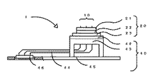
プリント配線板の検査ついて、一般的な構成を図1で説明する。検査治具1は被検査プリント配線板と検査装置の間に配置されて、導電を確保し抵抗値などの電気特性が検査される。被検査プリント配線板の検査端子に導電接触する複数の接触子10を保持する接触子保持体20、この接触子保持体20を支持して接触子10と導電接触する電極を有する電極部40はコネクタ46を介して検査装置と接続されている。この接触子保持体20と電極部40を分離可能にする構成は、製作と保守に有効である。A general configuration for inspection of a printed wiring board will be described with reference to FIG. The
検査治具1の接触子10などの具体的な構造について、特許文献1から図10によって述べる。接触子10は接触針11とコイルばね14からなり、リード線44の端部の電極41に導電接触される。接触針11は第1案内板21と第2案内板22に保持されて、コイルばね14はコイルばね保持板23に保持されて、電極41は電極板42の電極孔411に接着剤411aで接着されている。電極41とコイルばね14との位置ずれによる接触不良を回避するために、空隙51を電極41の外周に設けて、電極41とコイルばね14の導電接触を確保している。A specific structure of the
しかし、この電極41は銅の単線に皮膜したエナメル線であり、周辺から突出しているので、物理的な強度は弱くなり、製作と保守において損傷すると修復が困難で取り扱いが容易でない。However, since this
特許文献2においては、図10と構成が少し異なるが、エナメル線の周辺の電極孔411に接着剤411aを充填して接着するので、位置ずれが発生し、コイルばね14との相対的な位置ずれが無視できないために、コイルばね14と電極41の間に先端が円錐の導電性の当接部材(文献2符号9)を配置してコイルばね14の中心を電極41に当接させている。しかし、部品が1個増えるので製作コストはその分高くなり、組立、保守の労力も増す。In
特許文献3においては、円筒部材(文献3符号413)の電極にコイルばね(文献3符号22)を先細り形状に端末処理して、円筒部材の内側の端面に当接して係合を確実にして導電接触をしている。しかし、円筒部材の電極が必要でコスト高となる。In
特許文献4の(第3,5の実施例)、(図3、5)に導電接触子(文献4符号15、20)は下側針状体(文献4符号13、19)とコイルばね(文献4符号16)が半田付けされてなり、コイルばねの一端部(文献4符号16a)が絶縁体の開口部(文献4符号7a)から突出するように構成されている。しかし、一端部(文献4符号16a)の端末の加工はコイル中心径が小さくなると容易でない。In Patent Document 4 (Examples 3 and 5), (FIGS. 3 and 5), the conductive contact (
部品点数を最小の1個にした接触子の先行技術として、特許文献5にプローブ(文献5符号1)はコイル状に形成され一端部を中心軸に延設して、端末を円錐に加工し先端とし他端部も中心軸の他端側に延設して円錐に加工し電極との導電接触をしている。しかし、コイルばねの両側の端末処理は加工が複雑で製作が容易でない。As a prior art of a contactor having a minimum number of parts, in
特許文献6は、コイルばねの両側を密着巻きのテーパ状の先細り部を設けて端末を小径巻きに形成して、コイルばね保持体から両端が突出して保持されて、電極と検査端子に圧接されると導電接触をする。しかし、小径巻きの最小外径にはコイルばねの特性で線径の4倍の限界があり、コイル中心径の小さい微細コイルばねの制約になっている。検査端子の表面の面積が大きいか突起している場合は有効であるが、面積の小さい又は周辺にレジストがある凹んだ検査端子との接触が困難になる。In
特許文献7の(図2、3、4、6、7)にコイルばねのコンタクトピン(文献7符号1,51)の中心に端末の当接部(文献7符号7、11、57)を設けた、バーインテストに使用される例がある。しかし、圧接時に被検査物の検査端子への打跡、疵の可能性があり使用範囲に制限がある。In Patent Document 7 (FIGS. 2, 3, 4, 6, 7), a terminal contact portion (Reference 7, Reference 7, 57) is provided at the center of a contact pin (Reference 7, Reference 51) of a coil spring. There are also examples used for burn-in testing. However, there is a possibility of dents and wrinkles on the inspection terminal of the object to be inspected during pressure contact, and there is a limit to the range of use.
接触子の電気特性の直流抵抗とインダクタンス(交流抵抗)を改善する例として、特許文献8から図11に示している。峡ピッチICパッケージ用ICソケットに使用するコンタクトピン(接触子)140でプランジャー141とコイルバネユニット145が同軸に重合して配置されてICソケットに保持されてなる。Examples of improving the DC resistance and inductance (AC resistance) of the electrical characteristics of the contact are shown in
端子部142の先端が被検査ICパッケージの半田ボールなどの検査端子と接触し、コイルバネユニット145の密着細巻き部148の端末が検査装置と接続されている電極と接触する。心棒部141の幅広部143がICソケットとコイルバネユニット145とを係止して使用される。心棒部144が密着巻き部147の内周と摺動して伸縮し、検査時のコンタクトピン(接触子)140の内部抵抗を改善している。しかし、特許文献6と同様に細巻き部分に相当する電極の外径の確保が必要になる。The tip of the terminal portion 142 comes into contact with an inspection terminal such as a solder ball of the IC package to be inspected, and the terminal of the tightly wound portion 148 of the coil spring unit 145 comes into contact with an electrode connected to the inspection device. The wide portion 143 of the mandrel 141 is used by locking the IC socket and the coil spring unit 145. The mandrel portion 144 slides and expands and contracts with the inner periphery of the tightly
同様のコイルばねの端末として特許文献9において、(文献9図7)に縮径密巻き部(文献9符号5c)がある。しかし、不都合は特許文献6、8と同様である。As a terminal of a similar coil spring, in Patent Document 9, there is a reduced-diameter densely wound portion (Reference 9 code 5c) (Reference 9 FIG. 7). However, the inconvenience is the same as in
電極と導電接触を確実にする円錐の形状になった先行技術として、特許文献10に受けピン(文献10符号3)の基端部(文献10符号3b)がある。しかし、部品点数が増え、受けピン(文献10符号3)の加工が複雑であり、製作コストが上がる。
上記のように、検査治具1と接触子10に各種の工夫がなされているが、それぞれに問題 点を有している。As a prior art having a conical shape that ensures conductive contact with an electrode,
As described above, various efforts have been made to the
近年、電子機器の小型化が進行し、プリント配線板や電子部品などの微細化と高密度化が進み、検査端子の増加と、検査間隔の微細化に反比例し接触子の高単価化することが相乗して、検査治具の価格が騰貴しコスト低減が重要な課題となっている。
本発明は、上記の課題に鑑みてなされたもので、製造容易として安価に製造できるだけでなく保守も容易な、接触子と電極との導電接触を確実にすることと、接触子の電気特性の直流抵抗と交流インダクタンスの改善ができるプリント配線板に通電する検査治具及び接触子を提供することを目的とする。In recent years, downsizing of electronic equipment has progressed, and miniaturization and high density of printed wiring boards, electronic parts, etc. have progressed, and the cost of contacts has increased in inverse proportion to the increase in inspection terminals and miniaturization of inspection intervals. As a result, the cost of inspection jigs has risen and cost reduction has become an important issue.
The present invention has been made in view of the above-mentioned problems. It is easy to manufacture and can be manufactured inexpensively as well as easy to maintain, ensuring the conductive contact between the contact and the electrode, and the electrical characteristics of the contact. It is an object of the present invention to provide an inspection jig and a contact for energizing a printed wiring board capable of improving DC resistance and AC inductance.
本発明のうち第1の態様に係る検査治具は、プリンド配線板などの電子部品に備えられた検査端子に先端が接触される接触子、検査装置と接続する電極部を備える検査治具において、電極部は検査装置と接続されるコネクタ、そのコネクタから配線された電極は電極板の表面にコイルばねと同軸に配設されてなり、接触子は導電性の接触針とコイルばねとが直列に配置され、接触針は先端、突出部、大径部、中継部からなり、コイルばねは中継端、ばね定数部、電極端からなり、接触子保持体に保持されて電極板に着脱可能に搭載され初期荷重を有し、接触子保持体は接触針を検査端子に案内し係止する案内板とコイルばねを保持するコイルばね保持板からなり、コイルばねの電極端は端末において中心方向に曲げられて中心近傍に切断があることを特徴とする。 An inspection jig according to the first aspect of the present invention is an inspection jig including a contact whose tip is in contact with an inspection terminal provided in an electronic component such as a printed wiring board, and an electrode portion connected to the inspection device. The electrode part is a connector connected to the inspection device, and the electrode wired from the connector is arranged on the surface of the electrode plate coaxially with the coil spring, and the contact is made up of a conductive contact needle and a coil spring in series. The contact needle consists of a tip, protrusion, large-diameter part, and relay part, and the coil spring consists of a relay end, spring constant part, and electrode end, and is held by a contact holder and can be attached to and detached from the electrode plate It is mounted and has an initial load. The contact holder is composed of a guide plate that guides and locks the contact needle to the inspection terminal and a coil spring holding plate that holds the coil spring. Bent and there is a cut near the center It is characterized in.
本発明のうち第2の態様に係る検査治具は、プリンド配線板などの電子部品に備えられた検査端子に先端が接触される接触子、検査装置と接続する電極部を備える検査治具において、電極部は検査装置と接続されるコネクタ、そのコネクタから配線された電極は電極板の表面にコイルばねと直列に配設されてなり、接触子は導電性の接触針とコイルばねからなり、接触針は先端、突出部、中継部を有し、コイルばねは中継端、ばね定数部、電極端からなり、中継部の外周と中継端の内周とが連結されて連結部を形成し一体となり、接触子保持体に保持されて電極板に着脱可能に搭載され初期荷重を有し、接触子保持体は接触針を検査端子に案内し係止する案内板とコイルばねを保持するコイルばね保持板からなり、コイルばねの電極端は端末において中心方向に曲げられて中心近傍に切断があることを特徴とする。 An inspection jig according to a second aspect of the present invention is an inspection jig including a contact whose tip is in contact with an inspection terminal provided in an electronic component such as a printed wiring board, and an electrode portion connected to the inspection device. The electrode part is a connector connected to the inspection device, the electrode wired from the connector is arranged in series with the coil spring on the surface of the electrode plate, the contact consists of a conductive contact needle and a coil spring, The contact needle has a tip, a protruding part, and a relay part. The coil spring consists of a relay end, a spring constant part, and an electrode end. The outer periphery of the relay part and the inner periphery of the relay end are connected to form a connection part. A coil spring that holds a coil spring and a guide plate that is held by the contact holder and is detachably mounted on the electrode plate and has an initial load, and the contact holder guides and locks the contact needle to the inspection terminal. It consists of a holding plate and the electrode end of the coil spring is at the end Bent Oite central direction, characterized in that there is cut near the center.
本発明のうち第3の態様に係る接触子は、プリンド配線板などの電子部品に備えられた検査端子と先端が接触され、電極端と検査装置に接続されている電極とを接触する接触子において、接触子は導電性の接触針とコイルばねからなり、接触針は先端、突出部、大径部、中継部からなり、コイルばねは中継端、ばね定数部、電極端からなり、接触子保持体に保持されて電極と検査端子とに圧接されて導電接触し、コイルばねの電極端は端末において中心方向に曲げられて中心近傍に切断があることを特徴とする。 The contact according to the third aspect of the present invention is a contact that makes contact between an inspection terminal provided on an electronic component such as a printed wiring board and the tip, and makes contact between the electrode end and an electrode connected to the inspection device. The contact needle is composed of a conductive contact needle and a coil spring, the contact needle is composed of a tip, a protrusion, a large diameter portion, and a relay portion, and the coil spring is composed of a relay end, a spring constant portion, and an electrode end. It is held by the holding body and is brought into pressure contact with the electrode and the inspection terminal to be in conductive contact, and the electrode end of the coil spring is bent in the center direction at the terminal and is cut near the center.
本発明のうち第4の態様に係る接触子は、プリンド配線板などの電子部品に備えられた検査端子と先端が接触され、電極端と検査装置に接続されている電極とを接触する接触子において、接触子は導電性の接触針とコイルばねからなり、接触針は先端、突出部、中継部からなり、コイルばねは中継端、ばね定数部、電極端からなり、中継部の外周と中継端の内周とが連結されて連結部を形成し一体となり、接触子保持体に保持されて電極と検査端子とに圧接されて導電接触し、コイルばねの電極端は端末において中心方向に曲げられて中心近傍に切断があることを特徴とする。 The contact according to the fourth aspect of the present invention is a contact that makes contact between an inspection terminal and a tip provided in an electronic component such as a printed wiring board and contacts an electrode end and an electrode connected to the inspection device. The contact needle is composed of a conductive contact needle and a coil spring, the contact needle is composed of a tip, a projecting portion, and a relay portion, and the coil spring is composed of a relay end, a spring constant portion, and an electrode end. The inner periphery of the end is connected to form a connecting portion and is integrated, held by the contact holder and pressed into contact with the electrode and the inspection terminal, and the electrode end of the coil spring is bent toward the center at the terminal. And there is a cut near the center.
本発明のうち第5の態様に係る接触子は、第2又は第4の態様に係る接触子において、接触針は中継部と連続して突出部と反対側に延設してコイルばねの伸縮を案内する延設部を有することを特徴とする。 The contact according to the fifth aspect of the present invention is the contact according to the second or fourth aspect, wherein the contact needle extends continuously to the opposite side of the projecting portion with the extension of the coil spring. It has the extended part which guides.
本発明のうち第6の態様に係る接触子は、第1乃至第5のいずれかの態様に係る接触子において、コイルばねの中継端は縮径されたことを特徴とする。 The contact according to the sixth aspect of the present invention is characterized in that, in the contact according to any one of the first to fifth aspects, the relay end of the coil spring is reduced in diameter.
本発明のうち第7の態様に係る接触子は、第1乃至第6のいずれかの態様に係る接触子において、コイルばねの電極端を切断した切断線は前記コイルばねの中心方向又は円周方向にあることを特徴とする。 The contact according to the seventh aspect of the present invention is the contact according to any one of the first to sixth aspects, wherein the cutting line that cuts the electrode end of the coil spring is the center direction or the circumference of the coil spring. It is in the direction.
本発明のうち第8の態様に係る接触子は、第1乃至第7のいずれかの態様に係る接触子において、接触子の接触針とコイルばねは直列又は重合して配置されたことを特徴とする。 The contact according to an eighth aspect of the present invention is the contact according to any one of the first to seventh aspects, wherein the contact needle of the contact and the coil spring are arranged in series or in superposition. And
本発明のうち第9の態様に係る接触子は、第1乃至第8のいずれかの態様に係る接触子において、接触針は突出部と中継部の間に大径部を有することを特徴とする。 The contact according to a ninth aspect of the present invention is the contact according to any one of the first to eighth aspects, wherein the contact needle has a large diameter portion between the protruding portion and the relay portion. To do.
本発明のうち第10の態様に係る接触子は、第1乃至第9のいずれかの態様に係る接触子において、接触針には係止のための大径部がないことを特徴とする。 The contact according to the tenth aspect of the present invention is the contact according to any one of the first to ninth aspects, wherein the contact needle does not have a large-diameter portion for locking.
発明に共通する効果として、コイルばねの電極端の端面がコイルばねの中心近傍にあるので、電極部の電極が小さい、位置ずれがある場合も接触子保持体に保持された接触子の電極端との導電接触が確実に確保されるので検査の信頼性を確保できる。そして、検査間隔の微細な検査治具の製作と保守が容易なので長期的にもコスト低減となる。As an effect common to the invention, since the end face of the electrode end of the coil spring is in the vicinity of the center of the coil spring, the electrode end of the contact held by the contact holder even when the electrode of the electrode portion is small or misaligned Therefore, the reliability of inspection can be ensured. And since it is easy to manufacture and maintain an inspection jig with a fine inspection interval, the cost can be reduced over the long term.
本発明のうち第1の態様に係るものに依れば、検査治具の組立と保守において案内板が着脱可能で不良の接触子の交換も容易である。コイル端末処理と付勢により検査治具の内部の導電接触を確保するのでコスト低減に適合する。先端の位置と高さを案内し検査端子への打跡、疵を最小にしている。又接触針を傾斜させることで電極と検査端子の間隔を変換し微小間隔の検査も容易にできる。又検査端子の小変更に案内板の変更で対応できることがある。According to the first aspect of the present invention , the guide plate is detachable in the assembly and maintenance of the inspection jig, and replacement of defective contacts is easy. Coil end treatment and energization ensure conductive contact inside the inspection jig, which is suitable for cost reduction. The position and height of the tip are guided to minimize dents and wrinkles on the inspection terminal. In addition, by inclining the contact needle, the distance between the electrode and the inspection terminal can be converted to easily inspect the minute distance. In some cases, a small change in the inspection terminal can be handled by changing the guide plate.
本発明のうち第2の態様に係るものに依れば、接触子保持体は複数の絶縁板を一体とすると、接触子の傾斜に好都合である。案内板を1枚にすると構成が簡素になる。顧客の要求仕様に合わせて設計、製作が容易である。According to the second aspect of the present invention, if the contact holder is integrated with a plurality of insulating plates, it is convenient for the inclination of the contact. If the number of guide plates is one, the configuration becomes simple. Easy to design and manufacture according to customer's required specifications.
本発明のうち第3の態様に係るものに依れば、接触針とコイルばねが分離しているので、組立が並行して行えるので工期が短縮する。突出部と大径部を太径としスルーホールの検査端子に対応が容易である。
本発明のうち第4の態様に係るものに依れば、接触針とコイルばねは連結部で導電接続となり接触子の内部電気特性が良くなる。According to the third aspect of the present invention , the contact needle and the coil spring are separated from each other, so that the assembly can be performed in parallel and the construction period is shortened. The protruding part and the large-diameter part have a large diameter, and it is easy to cope with inspection terminals for through holes.
According to the fourth aspect of the present invention , the contact needle and the coil spring are electrically connected at the connecting portion, and the internal electrical characteristics of the contact are improved.
本発明のうち第5の態様に係るものに依れば、延設部がコイルばねの伸縮を同軸に案内し導電接触するので、コイルばねの直流抵抗とインダクダンスを改善する比率が大きい。そして、コイルばねの荷重を電極から検査端子に伝達の効率が良く両端の導電接触を確実にする。接触子の両端が同軸の円錐として機能し接触子として好都合である。According to the fifth aspect of the present invention, since the extending portion guides the expansion and contraction of the coil spring coaxially and makes conductive contact, the ratio of improving the DC resistance and the inductance of the coil spring is large. And the efficiency of transmission of the load of a coil spring from an electrode to an inspection terminal is good, and the conductive contact of both ends is ensured. Both ends of the contactor function as a coaxial cone, which is convenient as a contactor.
本発明のうち第6の態様に係るものに依れば、棒状部材から接触針の加工が容易で溶接などの接合なしで一体の接触子ができる。又溶接などの接合をすると接触針の加工はより簡素となりコスト低減となる。中継部と握着又は係合に好都合である。According to the sixth aspect of the present invention, the contact needle can be easily processed from the rod-shaped member, and an integral contact can be made without joining such as welding. Further, when joining such as welding, the processing of the contact needle becomes simpler and the cost is reduced. Convenient for gripping or engaging with the relay section.
本発明のうち第7の態様に係るものに依れば、接触子の接触荷重が小さい条件から大きい場合まで、同一径の電極の使用範囲が拡大し設計と製作が容易になる。
本発明の各々の態様の効果は、共通手段をコイルばねの電極端の中心近傍の切断としているので、他の態様の効果にもなる共通の事項がある。According to the seventh aspect of the present invention, the range of use of the electrodes having the same diameter is expanded from the condition where the contact load of the contactor is small to the case where the contact load is large, and the design and manufacture become easy.
Since the effect of each aspect of the present invention is to cut the common means near the center of the electrode end of the coil spring, there is a common matter that can be the effect of other aspects .
本発明のうち第8の態様に係るものに依れば、重合して配置すると、物理、電気特性を改善する。電気特性が顧客要求仕様に適合すれば製作容易でコスト低減となる。
本発明のうち第9の態様に係るものに依れば、大径部が係止を確実にする。接触子は一体となるので保守が容易である。
本発明のうち第10の態様に係るものに依れば、接触針に大径部がないので、接触針の加工が容易でコスト低減する。According to the eighth aspect of the present invention , physical and electrical properties are improved when polymerized. If the electrical characteristics meet customer requirements, manufacturing is easy and cost is reduced.
According to the ninth aspect of the present invention , the large diameter portion ensures locking. Maintenance is easy because the contacts are integrated.
According to the tenth aspect of the present invention, since the contact needle does not have a large diameter portion, the processing of the contact needle is easy and the cost is reduced.
接触子10と電極部40の電極41とを確実に導電接触し、電気特性も改善する検査治具1を製作と保守が容易に実現した。
(実施の形態1) The
(Embodiment 1)
本発明の実施形態の検査治具1は、図1に示すように、複数の接触子10は接触子保持体20に保持されて、電極板42に着脱可能に装着されている。電極板42には図2に示す電極41が接触子10のコイルばね12と同軸に配設されて支持体43に固着している。支持体43はコネクタ46と共に治具ベース板45に固着されている。電極41とコネクタ46はリード線44で配線されて電極部40を形成している。検査治具1が検査装置に搭載されて、コネクタ46を介して電気的に接続される。接触子10の先端111が被検査プリント配線板の検査端子に圧接して電気特性を測定することができることになる。As shown in FIG. 1, the
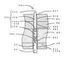
図2及び図3において、内部の構成を説明する。接触子10は接触針11とコイルばね12を直列に配置してなる。導電性金属の接触針11は先端111、突出部112、大径部113、中継部114からなり、先端111は導電接触を確実にするために60度の円錐となっている。突出部112は接触子保持体20の第1案内板21から伸縮可能に突出して被検査プリント配線板の検査端子との圧接を確保している。大径部113は接触子保持体20に保持されるために係止の機能をする第1案内孔211、第2案内孔221より大きい径になっている。なお、第1案内孔211、第2案内孔221は本発明の「案内部」 の一具体例に相当する。また、大径部113の上面が当接する第1案内孔211の下端縁 部は、本発明の「係止部」の一具体例に相当する。中継部114は突出部112の反対側に延設して90度の円錐の端面でコイルばね12と係合して導電接触する。材質はSK4、表面処理は金めっきしているが、先端形状と合わせて使用条件により各々を変更しても良い。The internal configuration will be described with reference to FIGS. The
接触針11は第1案内板21と第2案内板22に保持されている。第1案内板21には先端111を被検査プリント配線板の検査端子に案内する第1案内孔211と大径部113が移動可能な第1貫通孔212が同軸に形成されている。第2案内板22には大径部113が移動可能な第2貫通孔222とコイルばね12に案内する第2案内孔221が同軸に形成されている。第1案内板21と第2案内板22は螺子で固着して案内板25を形成している。The
コイルばね12はピアノ線などの導電性の金属で、接触針11を付勢してコイルばね保持板23に保持されている。コイルばね保持板23にはコイルばね12が伸縮可能なコイルばね保持孔231が第2案内孔221と電極孔411とに同軸に形成されている。コイルばね12の表面処理は導電接触を確実にするために金めっきが望ましい。なお、コイルば ね保持孔231は、本発明の「筒状空洞部」の一具体例に相当する。 The
電極41は電極板42にコイルばね保持孔231と同軸の電極孔411にエナメル線などのリード線44が挿入されて接着剤411aで固定されて平面加工されている。図においてコイルばね12と電極41とが同軸の中心近傍で導電接触している。電極41の表面処理も導電接触を確実にするために金めっきが望ましい。The
電極41の固定において、細径のリード線44と電極孔411のクリアランスを大きくすると挿入と接着は容易になるが電極41の位置ずれは大きくなる。この製作法は製作に適正なクリアランスに相当する位置ずれが発生するが、電極41として個別部品は要らず間隔を小さくできる。When the
接触子保持体20に保持されて接触子10は電極部40に搭載されているので、コイルばね12に付勢が掛けられて圧接の前に初期荷重を有する。これは、接触子10の内部接触の中継端122と電極端121とが導電接触している状態にあり、多数の接触子10の確実な導電接触を確保することができる。又接触針11は係止されているので突出部112の高さが均一に、小さくすることができ、検査端子の打跡、疵と検査治具1の寿命に好都合である。Since the
本発明のコイルばね12について、図3において説明する。コイルばね12は接触針11の中継部114の端面と係合する中継端122、コイルばね12の伸縮特性を有するばね定数部123、電極41と導電接触する電極端121からなる。中継端122の端末処理はクローズドエンドの無研磨としている。The
電極端121は、端末処理として、コイルばね中心線125を横切るように曲げられて、コイルばね中心線125の近傍で切断されている。製作仕様上は電極端121と電極41とが接触する端点をコイルばね中心線125としている。そして、コイルばね12は、製作上の誤差(バラツキ)とコイル巻線機の制約等は使用可能な範囲で認められる容易な形状をなしている。図3(a)は正面図、図3(b)は底面図、図3(c)は右側面図であ る。図3は、線径がd、コイル中心径がD、ばね指数(c=D/d)が3の最小の細巻きのばね定数部123と、電極端121の端面処理の様子を示している。電極端121は、特に急激に曲げられることなく方向が変わっており、コイルばね中心線125を横切っている。The electrode end 121 is bent so as to cross the coil
電極端121がコイルばね中心線125の近傍にあるので、電極41とコイルばね12との相対的な位置ずれの許容度を大きくすることができる。これは、位置ずれの可能性のあるリード線44を接着して形成する電極41や面積の小さな電極41なども対応することができ、検査間隔の微細な検査治具1の製作を容易にすることになる。Since the electrode end 121 is in the vicinity of the coil
図4には電極端121の電極41との接触の状態を拡大表示して模式的に示している。図 4(a)はコイルばね12の線材がコイルばね中心線125を横切った位置で切断線121aの端点がコイルばね中心線125の円錐の頂点になるように両刃のカッターで切断されている。電極端121の端面は切断により鋭利に形成されるので、低荷重でも確実な導電接触をすることができる。電極41との接触角θは、ばね定数部123と同じオープンエンドの角度から60度にするのが望ましい。図4(b)はその底面図である。切断時に線材の変形があり切断線121aの長さは線径よりも広くなるが図4では特に表示はしていない。電極端121が略円錐の形状になっており接触子10として好都合である。FIG. 4 schematically shows an enlarged view of the contact state of the electrode end 121 with the
図4(c)は切断線121aがコイルばね中心線125の円周方向に形成されている。電極端121の接触端面は切断によるコイルばね12の線材の円周になり切断線121aの鋭利な端でないので、コイルばね12の使用荷重が大きい時、電極41の物理強度が弱い時に採用すると長期に安定した導電接触が得られて好都合である。図4(d)はその底面図である。 In FIG. 4C, the cutting line 121 a is formed in the circumferential direction of the coil
接触子保持体20と接触子10の組立と保守について図1,2を参照して説明する。接着 剤411aによるリード線44の取り付けを含めて組立完了した電極部40の電極板42にコイルばね保持板23を整合して装着する。そしてコイルばね12を全てのコイルばね保持孔231に電極端121を前方にして挿入する。この作業と並行して、第2案内板22を少し浮かして置き、接触針11を全ての第2貫通孔222に中継部114を前方に挿入する。そして第1案内板21を整合して重ね螺子止めする。この案内板25をコイルばね保持板23に整合して重ね螺子で装着する。これで検査治具1の組立は完了する。Assembly and maintenance of the
接触子10の交換作業は、案内板25を取り外して不良のコイルばね12を交換する。そして、案内板25を少し浮かして置き、第1案内板21を取り外して不良の接触針11を交換する。各板を整合する場合、図には示していないが、位置合わせピンと位置合わせ孔を整合すると機械的な位置が決まる構成になっているので作業は容易である。
(実施の形態2) In the replacement operation of the
(Embodiment 2)
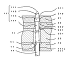
電極41の間隔より小さな微小な間隔の検査端子を検査する場合、図2において、第1案内孔211と第2案内孔221とを同軸でなくシフトして接触針11を少し傾斜させて、コイルばね12と直列に配置し、隣接の先端111との間隔を小さくして対応することができる。又被検査プリント配線板に一部に設計変更があり検査端子の位置が少しシフトした場合に、第1案内板21、第2案内板22を交換することで対応することができる場合がある。シフトの距離が大きい場合には、図には示していないが案内板25と接触針11の長さ、大径部113の位置等の変更をすることもできる。
(実施の形態3) When inspecting an inspection terminal having a minute interval smaller than the interval between the
(Embodiment 3)
スルーホールのプリント配線板を検査する場合、検査端子としてスルーホールランドが存在することがある。スルーホールランドには孔があり、その穴に接触子10の突出部112が入り接触不良となるので、孔径より大きい径の突出部112の接触針11が必要になる。コイルばね12も荷重、線径、外径も大きくなる。孔のない表面実装ランド等の検査端子に使用する細径の接触子10と混在する場合にも、同一径の電極41で対応できる範囲が拡大し設計と製作の容易性が増す。荷重の大きいコイルばね12に対して物理的な強度が十分でない時は図4の(c)の円周方向の切断が好ましい。
(実施の形態4) When inspecting a printed wiring board having a through hole, a through hole land may exist as an inspection terminal. There is a hole in the through-hole land, and the protruding
(Embodiment 4)
接触針11の変形例を図5において説明する。棒状の接触針11aの外径はコイルばね12のコイル中心径Dと大体同じで、中継部114aはコイルばね12aの内径より少し大きい径に係止の位置から2mm程度切削加工されている。端末は90度の円錐となっている。コイルばね12aの中継端122aの端末処理は係止を確実にするためにクローズドエンドの研磨が好ましい。この中継端122aに接触針11aの中継部114aを係止の位置まで圧入し握着し連結部115を形成する。これで、連結された一体の接触子10aとなる。中継端122aの外径は第2案内孔221の径より大きいので第2案内板22に係止される。A modification of the
接触針11aは切削加工の部分が接触針11より少ないのでコスト低減になる。中継部114aと中継端122aとの連結を握着としたが導電接合であっても良い。連結部115が大径部113の機能をしている。第1貫通孔212と第2貫通孔222の径は大径部113がないので、第1案内孔211、第2案内孔221より少し大きい程度が好ましい。実施の形態1と比較すると、係止の位置が第1案内孔211から第2案内孔221に移動している。そして、組立と保守の手順が変わる。Since the contact needle 11a has fewer cutting parts than the
組立と保守については、まず接触針11aの中継部114aをコイルばね12aの中継端122aに圧入し一体の接触子10aを準備する。次に第1案内板21、第2案内板22、コイルばね保持板23を重ねて整合し螺子止めし、接触子保持体20とする。コイルばね保持板23を上側にして、接触子10aの先端111を前方にして(すなわち下方に向 けて)全てのコイルばね保持孔231に接触子10aを挿入する。組立済みの電極部40を90度に設置する。接触子10aが装着された接触子保持体20を電極板42に整合して螺子で固着する。これで、検査治具1の組立は完了する。 For the assembly and maintenance, the relay portion 114a of the contact needles 11a press-fitted into the relay end 122a of the coil spring 12a is first prepared a contact 10a of the integral. Next, the
不良の接触子10aの交換は、検査治具1を90度に設置して、接触子保持体20を取り外し不良の接触子10aを取り出して、良品の接触子10aを挿入する。接触子10aの挿入された接触子保持体20を単体で取り扱う場合、コイルばね12を下側にすると、全ての接触子10aが落下するので注意が必要であるが、手順は単純で容易である。
(実施の形態5) To replace the defective contact 10a, the
(Embodiment 5)
実施の形態4の変形例で、棒状部材の先端と中継部の端面を円錐に加工し接触針を形成し、コイルばね12aの内径を棒状の接触針と大体等しく製作し、コイルばね12の中継端122aを係止の位置まで挿入して溶接などで接合して連結部115を形成し一体の接触子とする。外観の形状は図5において、中継部114aの外径が突出部112まで棒状に連続することになる。接触針の加工が実施の形態4よりも簡単になる。接触針とコイルばね12とが固着した一体の接触子になるので、組立と保守は実施の形態4と同様になる。(実施の形態6) In a modification of the fourth embodiment, the tip of the rod-like member and the end face of the relay portion are processed into a cone to form a contact needle, and the inner diameter of the coil spring 12a is made approximately equal to that of the rod-like contact needle. The end 122a is inserted to the locking position and joined by welding or the like to form the connecting
図6に示す接触針11bは、延設部116を有する。当該延設部116は、実施の形態4の中継部114aと連続しており、コイルばね12の内径より少し小さい径を有し、突出部112の反対側において、圧接時にコイルばね12aの電極端121と干渉しない長さに延設されている。延設部116は、90度の円錐の端面により、伸縮するコイルばね12aの内側と摺動し伸縮を同軸に案内しつつコイルばね12aと導電接触する。 The contact needle 11b shown in FIG . The
圧接時、延設部116はコイルばね12aが圧縮する場合、ばね定数部123と摺動して圧縮を同軸に案内し導電接触する。コイルばね12aの電極端121の部分は通電時の直流抵抗と交流のインダクタンス成分として残ることになるが、ばね定数部123の部分が加算されないので電気特性の改善の比率が大きい。At the time of pressure contact, when the coil spring 12a is compressed, the extending
接触子10bの接触針11bとコイルばね12が同軸に伸縮動作するので電極端121の電極41と接触する端点は接触針11bの中心の近傍にあることになる。コイルばね保持孔231との干渉を避けて、コイルばね12の荷重を電極41と検査端子に効率良く伝え導電接触を確実にすることができる。
(実施の形態7) Since the contact needle 11b of the contact 10b and the
(Embodiment 7)
図7において、第1案内孔211、第2案内孔221、コイルばね保持孔231を同軸でなくシフトして接触子10bを少し傾斜させて、先端111の位置と電極41の位置を少しシフトしている。In FIG. 7, the
先端111と電極孔411の中心線411bの位置がAシフトしていることを示している。第1案内板21は検査端子の位置に第1案内孔211を加工する、反対面から第1貫通孔212を所定値シフトして加工し孔を連結する。第2案内板22は所定値シフトして第2貫通孔222を加工する、反対面から第2案内孔221を所定値シフトして加工し孔を連結する。It shows that the positions of the
コイルばね保持板23はコイルばね保持孔231aを所定値シフトして加工する、反対面からコイルばね保持孔231を所定値シフトして加工し孔を連結する。連結孔のコイルばね保持孔231とコイルばね保持孔231aとがシフトしているがコイルばね12は延設部116で案内されているので連結端での干渉はない。電極板42は電極孔411を所定値シフトして加工する。The coil
被検査プリント配線板に一部設計変更があり、検査端子の位置が少しシフトした場合にも、第1案内板21、第2案内板22、コイルばね保持板23を交換することで対応することができる場合がある。これは、接触子10bの接触針11bとコイルばね12が同軸に動作し両端を円錐として使用できる事例である。接触子10の全長を傾斜しているので位置の変換効率が良い。そして、接触針11の長さ、径などを変更することで適用の範囲を広げることもできる。
(実施の形態8)Even if the design of the printed wiring board to be inspected is partly changed and the position of the inspection terminal is slightly shifted, it is possible to cope with this by replacing the
(Embodiment 8)
実施の形態5と同じ技術思想で、棒状部材の先端と延設部の端面を円錐に加工し接触針を形成し、コイルばね12aの内径を棒状の接触針より少し大きく製作し、コイルばね12aの中継端122aを係止の位置まで挿入して溶接などで接合して連結部115を形成する。外観の形状は図6において、延設部116の外径が中継部114aと突出部112まで同一径で棒状に連続することになる。接触針の加工が簡単になる。
(実施の形態9) With the same technical idea as in the fifth embodiment, the tip of the rod-shaped member and the end surface of the extending portion are processed into a cone to form a contact needle, and the inner diameter of the coil spring 12a is made slightly larger than the rod-shaped contact needle, and the coil spring 12a The connecting end 115a is inserted to the locking position and joined by welding or the like to form the connecting
(Embodiment 9)
図8において説明する。棒状部材から形成された接触針11cの中継部114cは、コイルばね12の約線径分、突出部112より細い径であり、係止の位置から2mm程度の長 さである。延設部116は、テーパ状に元の棒状部材の径に戻るように加工されている。端末を縮径されたコイルばね12cの中継端122cを係止の位置まで圧入して握着されて連結部115を形成し一体となり、接触子保持体20に保持されるために、中継端12 2cは係止の機能もする。接触針11cの加工が容易であるとともに、連結のために溶接などによる接合は不要である。This will be described with reference to FIG. Relay portion 114c of the contact needles 11c formed from rod-like member is approximately the line diameter of the
コイルばね12cのばね定数部123の内径は棒状部材の外径より少し大きく延設部116に伸縮を案内される。中継端122cは線径dの1.5倍程度縮径されたクローズドエンドの研磨となっている。
(実施の形態10) The inner diameter of the spring constant portion 123 of the coil spring 12c is guided to extend and contract by the extending
(Embodiment 10)
図9に示す例では、第1案内板21の1枚で案内板25としている。接触子を垂直に配置する場合など、接触子保持体20の構成が簡素で好都合である。組立と保守は電極板42にコイルばね保持板23を固着し、接触子を挿入し、第1案内板21を整合し固着する。上側から作業出来るので好都合である。In the example shown in FIG. 9, one
接触子10dは中継部114dと中継端122cとを溶接などで接合し連結部115を形成し一体となっている。実施例5,8と同じ接合の図で、コイルばね12aを縮径の中継端122cのあるコイルばね12cにして握着し製作を容易にしている。縮径は握着する程度でよい。
(実施の形態11) The contact 10d is integrally formed by joining the relay portion 114d and the relay end 122c by welding or the like to form a connecting
(Embodiment 11)
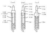
図12(a)に示す例では、接触針11とコイルばね12を使用して重合する配置とする。中継部114はコイルばね12の内径より少し小さい径を有し、コイルばね12の伸縮を案内し延設部116の機能もする。接触子の電気特性が顧客要求仕様に適合すればコスト低減となる。接触子保持体20は図6又は図9の構成が好ましい。又、接触針11とコイルばね12cを使用し、縮径した中継端122cを圧入すると1体化した接触子となる。
(実施の形態12) In the example shown in FIG. 12A, the
(Embodiment 12)
図12(b)に示す例では、接触針11eは先端111、突出部112、大径部113、中継部114a、延設部116からなり、適切な内径のコイルばね12を中継部114aに圧入し握着しても1体化した接触子となり保守が容易になる。又、延設部116をなしとしても良い。
(実施の形態13) In the example shown in FIG. 12B , the contact needle 11e includes a
(Embodiment 13)
図12(c)は接触針11fとコイルばね12cを直列に配置した場合の中継部114と中継端122cとの係合の別の例を示している。中継部114fは大径とし大径部113を兼ねて係止と、端面を90度の円錐に段付き加工し縮径の中継端122cを案内して係合を確実にしている。又、中継部114fは大径で端面は円錐の段付きなし、平面など、コストを優先しプレス等で大径を形成しても良い。突出部112を長くすると傾斜に好都合となる。 FIG. 12C shows another example of the engagement between the relay portion 114 and the relay end 122c when the contact needle 11f and the coil spring 12c are arranged in series. The relay portion 114f has a large diameter and also serves as the
中継部114、大径部113、突出部112を同径にしても良い。接触子保持体20に保持されて係止が掛らず初期荷重はなく内部接続の確実性は落ちるが加工が簡素でコスト低減する。又、コイルばねは縮径のないコイルばね12、12aであっても良い。延設部116を設けても良い。The relay portion 114, the
以上に述べた例では、コイルばね保持板23を1枚で構成しているが、その他の実施の形 態として、複数枚としても良い。又案内板は3枚以上でも良い。間隔を空けてもよい。 In the example described above, it constitutes a coil
実施の形態1において、コイルばね12aの中継端の端末処理がクローズドエンドの研磨の方が好ましい。又は縮径クローズドエンドの研磨のコイルばね12cは中継部114の端面に段付き加工を追加すると係合が安定し、コイルばね保持孔231との干渉が避けられ荷重特性も安定する。 In the first embodiment , the end treatment at the relay end of the coil spring 12a is preferably the closed end polishing. Alternatively, the coil spring 12c having a reduced diameter closed end is stably engaged when a stepped process is added to the end face of the relay portion 114, and interference with the coil
本発明の接触子は、プリント配線板、IC、ICパッケージ等の電子部品に備えられた電極端子に接触される検査装置全般に用いることができる。The contact of the present invention can be used for all inspection devices that are in contact with electrode terminals provided in electronic components such as printed wiring boards, ICs, and IC packages.
検査治具は、本発明の接触子を用いることができる通電治具に適用することができる。The inspection jig can be applied to an energization jig that can use the contact according to the present invention.
1・・・・検査治具
10,10a,10b,11c,10d・接触子
11,11a,11b,11c,11d,11e,11f・接触針
111・・先端
112・・突出部
113・・大径部
114,114a,114c,114d,114f・中継部
115・・連結部
116・・延設部
12,12a,12c・コイルばね
121・・電極端
121a・切断線
122,122a,122c・中継端
123・・ばね定数部
125・・コイルばね中心線
20・・・接触子保持体
21・・・第1案内板
22・・・第2案内板
23・・・コイルばね保持板
25・・・案内板
40・・・電極部
41・・・電極
42・・・電極板
44・・・リード線
46・・・コネクタ1 ...
Claims (8)
前記接触針は、検査対象電子部品の検査部位に接触する先端と、当該先端に続く軸状部分である突出部と、当該突出部に続き当該突出部よりも径の大きい軸状部分である大径部と、当該大径部に続き当該大径部よりも径の小さい軸状部分である中継部とを有しており、
前記コイルばねは、前記中継部と直列、又は前記中継部の外周に配置され、一端部が前記接触針の前記中継部又は前記大径部に当接して電気的に接続され、
他端部は、曲率半径を実質的に減少させることなく、かつ急激に曲げられることなく、ピッチ角を増加させてゆきつつ立体的に曲げられて、中心方向に方向を変えてコイルばね中心軸と交差する近傍に、切断された最端部があり、
前記コイルばねの径は、最小巻線径、又は当該最小巻線径に近い巻線径にある接触子。 A contactor incorporated and used in an inspection jig used for inspection of electronic components, comprising a conductive contact needle and a conductive coil spring,
The contact needle is a tip that is in contact with an inspection site of an electronic component to be inspected, a protrusion that is a shaft-like portion following the tip, and a shaft-like portion that is larger in diameter than the protrusion after the protrusion. It has a diameter part and a relay part that is a shaft-like part having a smaller diameter than the large diameter part following the large diameter part,
The coil spring is arranged in series with the relay portion or on the outer periphery of the relay portion, and one end portion is in contact with and electrically connected to the relay portion or the large diameter portion of the contact needle,
The other end portion is bent three-dimensionally while increasing the pitch angle without substantially reducing the radius of curvature and without being bent suddenly, and changes the direction in the central direction to change the central direction of the coil spring. and in the vicinity of intersecting, Ri endmost there cut,
Diameter of the coil spring, the minimum winding diameter or the winding diameter near Ru contacts close to the minimum winding diameter.
前記接触針は、検査対象電子部品の検査部位に接触する先端と、当該先端に続く軸状部分である突出部と、当該突出部に続く軸状部分である中継部とを有しており、
前記コイルばねは、一端部において内周が前記中継部の外周と連結されることにより前記接触針と一体となっており、
他端部は、曲率半径を実質的に減少させることなく、かつ急激に曲げられることなく、ピッチ角を増加させてゆきつつ立体的に曲げられて、中心方向に方向を変えてコイルばね中心軸と交差する近傍に、切断された最端部があり、
前記コイルばねの径は、最小巻線径、又は当該最小巻線径に近い巻線径にある接触子。 A contactor incorporated and used in an inspection jig used for inspection of electronic components, comprising a conductive contact needle and a conductive coil spring,
The contact needle has a tip that comes into contact with an inspection site of an electronic component to be inspected, a protruding portion that is a shaft-like portion following the tip, and a relay portion that is a shaft-like portion following the protrusion.
The coil spring is integrated with the contact needle by connecting an inner periphery with an outer periphery of the relay portion at one end.
The other end portion is bent three-dimensionally while increasing the pitch angle without substantially reducing the radius of curvature and without being bent suddenly, and changes the direction in the central direction to change the central direction of the coil spring. and in the vicinity of intersecting, Ri endmost there cut,
Diameter of the coil spring, the minimum winding diameter or the winding diameter near Ru contacts close to the minimum winding diameter.
前記接触針は、検査対象電子部品の検査部位に接触する先端と、当該先端に続く軸状部分とを有しており、
前記コイルばねは、一端部が前記接触針の前記軸状部分の前記先端とは反対側の端部に当接することにより前記接触針と電気的に接続されるものであり、
他端部は、曲率半径を実質的に減少させることなく、かつ急激に曲げられることなく、ピッチ角を増加させてゆきつつ立体的に曲げられて、中心方向に方向を変えてコイルばね中心軸と交差する近傍に、切断された最端部があり、
前記コイルばねの径は、最小巻線径、又は当該最小巻線径に近い巻線径にある接触子。 A contactor incorporated and used in an inspection jig used for inspection of electronic components, comprising a conductive contact needle and a conductive coil spring,
The contact needle has a tip that comes into contact with the inspection site of the electronic component to be inspected, and a shaft-like portion following the tip.
The coil spring is electrically connected to the contact needle by abutting one end of the coil spring against the end of the shaft-like portion opposite to the tip.
The other end portion is bent three-dimensionally while increasing the pitch angle without substantially reducing the radius of curvature and without being bent suddenly, and changes the direction in the central direction to change the central direction of the coil spring. and in the vicinity of intersecting, Ri endmost there cut,
Diameter of the coil spring, the minimum winding diameter or the winding diameter near Ru contacts close to the minimum winding diameter.
前記接触子保持体は、前記先端が露出するように前記接触針を軸方向に摺動可能に支持する案内部と、前記接触針の前記大径部、又は前記コイルばねの前記一端部に当接することにより、前記先端の所定以上の突出を係止する係止部と、前記コイルばねを収納する筒状空洞部と、を含み、
前記電極部は、前記接触子保持体に連結された電気絶縁性の電極板と、当該電極板を貫通するように当該電極板に固定され、一端面が前記コイルばねの前記最端部に当接することにより、電気的に接続されるとともに、前記コイルばねを付勢する軸状の導電性の電極と、を備える検査治具。 An inspection jig used for inspecting an electronic component, wherein the contact according to any one of claims 1 to 6 , a contact holder holding the contact, and connected to the contact holder An electrode portion,
The contact holder supports a guide portion that slidably supports the contact needle in an axial direction so that the tip is exposed, and the large diameter portion of the contact needle or the one end portion of the coil spring. Including a locking portion that locks a predetermined protrusion or more of the tip by contacting, and a cylindrical cavity portion that houses the coil spring,
The electrode portion is fixed to the electrode plate so as to penetrate the electrode plate and the electrically insulating electrode plate connected to the contact holder, and one end surface of the electrode portion contacts the outermost end portion of the coil spring. An inspection jig comprising: a shaft-like conductive electrode that is electrically connected by contact and urges the coil spring.
Priority Applications (3)
| Application Number | Priority Date | Filing Date | Title |
|---|---|---|---|
| JP2010229524A JP5345598B2 (en) | 2010-09-01 | 2010-10-12 | Inspection jig and contact |
| PCT/JP2011/065930 WO2012014673A1 (en) | 2010-07-29 | 2011-07-13 | Inspection jig and contact |
| CN2011800368770A CN103026242A (en) | 2010-07-29 | 2011-07-13 | Inspection jig and contact |
Applications Claiming Priority (3)
| Application Number | Priority Date | Filing Date | Title |
|---|---|---|---|
| JP2010195592 | 2010-09-01 | ||
| JP2010195592 | 2010-09-01 | ||
| JP2010229524A JP5345598B2 (en) | 2010-09-01 | 2010-10-12 | Inspection jig and contact |
Related Child Applications (1)
| Application Number | Title | Priority Date | Filing Date |
|---|---|---|---|
| JP2013097215A Division JP2013156275A (en) | 2010-09-01 | 2013-05-06 | Inspection jig and contactor |
Publications (3)
| Publication Number | Publication Date |
|---|---|
| JP2012073213A JP2012073213A (en) | 2012-04-12 |
| JP2012073213A5 JP2012073213A5 (en) | 2012-07-12 |
| JP5345598B2 true JP5345598B2 (en) | 2013-11-20 |
Family
ID=46169526
Family Applications (2)
| Application Number | Title | Priority Date | Filing Date |
|---|---|---|---|
| JP2010229524A Expired - Fee Related JP5345598B2 (en) | 2010-07-29 | 2010-10-12 | Inspection jig and contact |
| JP2013097215A Pending JP2013156275A (en) | 2010-09-01 | 2013-05-06 | Inspection jig and contactor |
Family Applications After (1)
| Application Number | Title | Priority Date | Filing Date |
|---|---|---|---|
| JP2013097215A Pending JP2013156275A (en) | 2010-09-01 | 2013-05-06 | Inspection jig and contactor |
Country Status (1)
| Country | Link |
|---|---|
| JP (2) | JP5345598B2 (en) |
Families Citing this family (4)
| Publication number | Priority date | Publication date | Assignee | Title |
|---|---|---|---|---|
| JP2013232356A (en) * | 2012-04-27 | 2013-11-14 | Junkosha Co Ltd | Coiled cable |
| JP5894718B2 (en) * | 2013-02-25 | 2016-03-30 | 秀雄 西川 | Contact, inspection jig, and method of manufacturing contact |
| JP6071633B2 (en) * | 2013-02-25 | 2017-02-01 | 秀雄 西川 | Contact, inspection jig, and method of manufacturing contact |
| JP2015004518A (en) * | 2013-06-19 | 2015-01-08 | 大西電子株式会社 | Inspection jig |
Family Cites Families (8)
| Publication number | Priority date | Publication date | Assignee | Title |
|---|---|---|---|---|
| JPS5543305Y2 (en) * | 1975-03-07 | 1980-10-11 | ||
| JP3326095B2 (en) * | 1996-12-27 | 2002-09-17 | 日本発条株式会社 | Conductive contact |
| JP2000046084A (en) * | 1998-07-27 | 2000-02-15 | Kgm:Kk | Coil spring |
| JP2001311746A (en) * | 2000-04-28 | 2001-11-09 | Mitsubishi Materials Corp | Contact probe and probe device |
| US7154286B1 (en) * | 2005-06-30 | 2006-12-26 | Interconnect Devices, Inc. | Dual tapered spring probe |
| JP4833011B2 (en) * | 2005-12-20 | 2011-12-07 | 株式会社エンプラス | Socket for electrical parts |
| JP4831614B2 (en) * | 2006-08-15 | 2011-12-07 | 株式会社ヨコオ | Kelvin inspection jig |
| JP2009047636A (en) * | 2007-08-22 | 2009-03-05 | Inoue Shoji Kk | Conduction inspection tool of printed circuit board |
-
2010
- 2010-10-12 JP JP2010229524A patent/JP5345598B2/en not_active Expired - Fee Related
-
2013
- 2013-05-06 JP JP2013097215A patent/JP2013156275A/en active Pending
Also Published As
| Publication number | Publication date |
|---|---|
| JP2012073213A (en) | 2012-04-12 |
| JP2013156275A (en) | 2013-08-15 |
Similar Documents
| Publication | Publication Date | Title |
|---|---|---|
| KR101098320B1 (en) | Inspection fixture, the electrode of the fixture, method of making the electrode | |
| US8519727B2 (en) | Contact probe and socket | |
| US8344747B2 (en) | Probe unit | |
| KR101415722B1 (en) | Contact probe and probe unit | |
| JP5824290B2 (en) | Inspection jig and contact | |
| JP5776687B2 (en) | Inspection contact and inspection jig | |
| JP2011191104A (en) | Contact probe and socket, manufacturing method of tube plunger, and manufacturing method of the contact probe | |
| JP5345598B2 (en) | Inspection jig and contact | |
| WO2011048890A1 (en) | Contact probe and socket | |
| JP2012073213A5 (en) | ||
| JP5394264B2 (en) | Probe unit | |
| US20100102841A1 (en) | Device, method and probe for inspecting substrate | |
| JP2021105547A (en) | Contact probe | |
| JP3154264U (en) | Probe unit for probe pin and board inspection | |
| WO2012014673A1 (en) | Inspection jig and contact | |
| JP5480075B2 (en) | Inspection jig and contact | |
| JP2013205190A (en) | Spring probe | |
| JP3183676U (en) | Probe pin for semiconductor inspection | |
| JP2002350487A (en) | Inspection jig for printed wiring board | |
| JP2010276579A (en) | Electric contact and inspection fixture provided with the same | |
| JP2012032315A (en) | Inspection tool and contact piece | |
| JP2012057995A5 (en) | ||
| CN103026242A (en) | Inspection jig and contact | |
| JP6410457B2 (en) | Contact, inspection jig, and method of manufacturing contact | |
| JPWO2007116963A1 (en) | Contact for board inspection and method for manufacturing the same |
Legal Events
| Date | Code | Title | Description |
|---|---|---|---|
| A521 | Request for written amendment filed |
Free format text: JAPANESE INTERMEDIATE CODE: A523 Effective date: 20120423 |
|
| A621 | Written request for application examination |
Free format text: JAPANESE INTERMEDIATE CODE: A621 Effective date: 20120423 |
|
| A871 | Explanation of circumstances concerning accelerated examination |
Free format text: JAPANESE INTERMEDIATE CODE: A871 Effective date: 20120425 |
|
| RD02 | Notification of acceptance of power of attorney |
Free format text: JAPANESE INTERMEDIATE CODE: A7422 Effective date: 20120423 |
|
| A521 | Request for written amendment filed |
Free format text: JAPANESE INTERMEDIATE CODE: A523 Effective date: 20120423 |
|
| A975 | Report on accelerated examination |
Free format text: JAPANESE INTERMEDIATE CODE: A971005 Effective date: 20120611 |
|
| A131 | Notification of reasons for refusal |
Free format text: JAPANESE INTERMEDIATE CODE: A131 Effective date: 20120620 |
|
| A521 | Request for written amendment filed |
Free format text: JAPANESE INTERMEDIATE CODE: A523 Effective date: 20120719 |
|
| A131 | Notification of reasons for refusal |
Free format text: JAPANESE INTERMEDIATE CODE: A131 Effective date: 20121017 |
|
| A521 | Request for written amendment filed |
Free format text: JAPANESE INTERMEDIATE CODE: A523 Effective date: 20121203 |
|
| A02 | Decision of refusal |
Free format text: JAPANESE INTERMEDIATE CODE: A02 Effective date: 20130204 |
|
| A521 | Request for written amendment filed |
Free format text: JAPANESE INTERMEDIATE CODE: A523 Effective date: 20130506 |
|
| A911 | Transfer to examiner for re-examination before appeal (zenchi) |
Free format text: JAPANESE INTERMEDIATE CODE: A911 Effective date: 20130514 |
|
| A912 | Re-examination (zenchi) completed and case transferred to appeal board |
Free format text: JAPANESE INTERMEDIATE CODE: A912 Effective date: 20130621 |
|
| A61 | First payment of annual fees (during grant procedure) |
Free format text: JAPANESE INTERMEDIATE CODE: A61 Effective date: 20130814 |
|
| R150 | Certificate of patent or registration of utility model |
Ref document number: 5345598 Country of ref document: JP Free format text: JAPANESE INTERMEDIATE CODE: R150 Free format text: JAPANESE INTERMEDIATE CODE: R150 |
|
| R250 | Receipt of annual fees |
Free format text: JAPANESE INTERMEDIATE CODE: R250 |
|
| R250 | Receipt of annual fees |
Free format text: JAPANESE INTERMEDIATE CODE: R250 |
|
| R250 | Receipt of annual fees |
Free format text: JAPANESE INTERMEDIATE CODE: R250 |
|
| R250 | Receipt of annual fees |
Free format text: JAPANESE INTERMEDIATE CODE: R250 |
|
| R250 | Receipt of annual fees |
Free format text: JAPANESE INTERMEDIATE CODE: R250 |
|
| R250 | Receipt of annual fees |
Free format text: JAPANESE INTERMEDIATE CODE: R250 |
|
| LAPS | Cancellation because of no payment of annual fees |