JP5343346B2 - Game machine - Google Patents
Game machine Download PDFInfo
- Publication number
- JP5343346B2 JP5343346B2 JP2007288278A JP2007288278A JP5343346B2 JP 5343346 B2 JP5343346 B2 JP 5343346B2 JP 2007288278 A JP2007288278 A JP 2007288278A JP 2007288278 A JP2007288278 A JP 2007288278A JP 5343346 B2 JP5343346 B2 JP 5343346B2
- Authority
- JP
- Japan
- Prior art keywords
- game
- state
- winning
- symbol
- display
- Prior art date
- Legal status (The legal status is an assumption and is not a legal conclusion. Google has not performed a legal analysis and makes no representation as to the accuracy of the status listed.)
- Active
Links
Images


Abstract
Description
本発明は、遊技機に関するものである。 The present invention relates to a gaming machine.
例えばパチンコ遊技機においては、表示画面に複数の絵柄を変動表示する絵柄表示装置を備えたものが知られている。かかる遊技機では、例えば遊技領域に設けられた作動口を遊技球が通過したことを契機として、遊技者に有利な当たり遊技状態に移行させるか否かの当たり抽選が行われると共に絵柄の変動表示が開始される。そして当たり抽選に当選した場合には、表示画面に特定絵柄の組み合わせ等が最終停止表示されると共に、遊技状態が当たり遊技状態に移行する。そして、当たり遊技状態への移行に伴い、例えば遊技領域に設けられた可変入賞装置の開閉が開始されるようになっている。 For example, a pachinko gaming machine is known that includes a picture display device that displays a plurality of pictures on a display screen. In such a gaming machine, for example, when a game ball passes through an operating port provided in a gaming area, a lottery is performed to determine whether or not to shift to a winning gaming state that is advantageous to the player, and a variation display of a picture is displayed. Is started. When a winning lottery is won, a combination of specific patterns and the like are finally displayed on the display screen, and the gaming state shifts to the winning gaming state. With the transition to the winning gaming state, for example, opening and closing of a variable winning device provided in the gaming area is started.
また、例えば絵柄の変動表示が行われている最中に遊技球が作動口を通過した場合、当たり抽選に用いる抽選情報等が予め定められた所定数(例えば4個)を上限として保留記憶される。抽選情報等が保留記憶された場合には、絵柄の変動表示が終了した後に、次回の絵柄の変動表示が開始されるようになっている。 In addition, for example, when a game ball passes through the operating port while the display of the change of the pattern is being performed, lottery information used for the winning lottery is reserved and stored with a predetermined number (for example, four) as an upper limit. The When lottery information or the like is stored on hold , the next variation display of the pattern is started after the variation display of the pattern is completed.
絵柄の変動表示についてより詳しくは、先ず絵柄が変動を開始し、所定数の絵柄が停止した際に当たり絵柄の組合せとなり得る組合せが成立するとリーチ演出が発生し、全ての絵柄が停止した際に当たり絵柄の組合せとなっていれば当たり遊技状態に移行するという流れが一般的である。そこで、当たり絵柄の組合せが最終停止表示されることへの期待感を高めるべく、種々のリーチ演出や予告演出等の補助演出を行う遊技機が提案されている(例えば特許文献1参照)。 In more detail about the display of the change of the pattern, first, when the pattern starts to change, when a predetermined number of patterns are stopped, a reach effect is generated when a combination that can be a combination of winning patterns is established, and when all the patterns stop, If it is a combination of the above, the flow of transition to the gaming state is common. Therefore, in order to increase the expectation that the combination of winning pictures will be finally stopped and displayed, a gaming machine that performs auxiliary effects such as various reach effects and notice effects has been proposed (for example, see Patent Document 1).
また、遊技機によっては、遊技状態として当たり遊技状態に移行することに当選する確率が通常遊技状態よりも高い高確率遊技状態が設定されている。さらに、上記高確率遊技状態には当たり遊技状態が終了した場合に移行する。当たり遊技状態が終了した場合に通常遊技状態又は高確率遊技状態のどちらに移行するかの抽選を、当たり遊技状態に移行するか否かの抽選と同じ時に行っている。
しかしながら、この場合には遊技機に必要以上の処理負荷がかかっていることが考えられる。 However, in this case, it is considered that a processing load more than necessary is applied to the gaming machine.
なお、以上の問題は高確率遊技状態に限らず、上記の如き当たり遊技状態を発生させ、当該当たり遊技状態が終了した場合に、当該当たり遊技状態とは異なる特定の遊技状態が発生するよう構成された他の遊技機にも該当する問題である。上記特定の遊技状態として例えば、高確率遊技状態に限らず時短遊技状態等が考えられる。 The above problem is not limited to the high-probability gaming state, and when the winning gaming state as described above is generated and the winning gaming state ends, a specific gaming state different from the winning gaming state is generated. This is also a problem that applies to other gaming machines that have been released. As the specific gaming state, for example, not only a high probability gaming state but also a short-time gaming state can be considered.
本発明は上記例示した事情等に鑑みてなされたものであり、処理負荷を軽減することが可能な遊技機を提供することを目的とするものである。 The present invention has been made in view of the above-described circumstances, and an object thereof is to provide a gaming machine capable of reducing the processing load.
本発明は、遊技が実行される遊技領域を備えた遊技機本体と、The present invention includes a gaming machine main body having a gaming area in which a game is executed,
前記遊技領域において上方及び正面視で左右両側を遊技球が通過可能となるよう設置され、絵柄が変動表示される絵柄表示手段と、In the game area, a picture display means that is installed so that a game ball can pass on both the left and right sides as viewed from above and in front, and the picture is displayed in a variable manner.
少なくとも前記左右両側のうち左側を流下する遊技球が通過可能な位置に設けられた第1入球口と、A first entrance opening provided at a position through which a game ball flowing down the left side of at least the left and right sides can pass;
前記左右両側のうち右側を流下する遊技球が通過可能な位置に設けられ、遊技球が入球し易い状態と入球しにくい状態とに切り換え可能な第2入球口と、A second entrance that is provided at a position where the game ball flowing down the right side of the left and right sides can pass, and that can be switched between a state where the game ball is easy to enter and a state where it is difficult to enter;
前記第1入球口を遊技球が通過した場合に第1情報を取得する第1情報取得手段と、First information acquisition means for acquiring first information when a game ball passes through the first entrance;
前記第1情報に基づいて、通常遊技状態よりも遊技者に有利な第1当たり遊技状態を発生させるか否かの抽選を実行する第1抽選手段と、First lottery means for executing a lottery to determine whether or not to generate a first winning gaming state that is more advantageous to the player than the normal gaming state based on the first information;
前記第1抽選手段により前記第1当たり遊技状態を発生させることに当選している場合、遊技状態を前記第1当たり遊技状態に移行させる第1遊技状態移行手段と、If the first lottery means is selected to generate the first winning gaming state, first gaming state transition means for shifting the gaming state to the first winning gaming state;
前記第1当たり遊技状態の後に前記通常遊技状態に移行させたり前記通常遊技状態よりも前記第2入球口に遊技球が入球し易い状態になり易くなる遊技状態に移行させたりする第2遊技状態移行手段と、After the first winning gaming state, a transition is made to the normal gaming state, or a transition is made to a gaming state that makes it easier for a gaming ball to enter the second entrance than the normal gaming state. Game state transition means;
前記第2入球口を遊技球が通過した場合に第2情報を取得する第2情報取得手段と、Second information acquisition means for acquiring second information when a game ball passes through the second entrance,
前記第2情報に基づいて、前記左右両側のうち右側を流下する遊技球が通過可能な位置に設けられた可変入賞手段が開放する第2当たり遊技状態を発生させるか否かの抽選を実行する第2抽選手段と、Based on the second information, a lottery is executed as to whether or not to generate a second winning gaming state that is opened by a variable winning means provided at a position where a gaming ball flowing down the right side of the left and right sides can pass. A second lottery means;
前記第2抽選手段により前記第2当たり遊技状態を発生させることに当選している場合、遊技状態を前記第2当たり遊技状態に移行させる第3遊技状態移行手段と、Third game state transition means for transitioning the gaming state to the second winning gaming state when the second lottery means is won to generate the second winning gaming state;
前記可変入賞手段への入球を検知する入球検知手段と、Entry detection means for detecting entry into the variable winning means,
前記入球検知手段による入球の検知がなされた場合、前記第2入球口に遊技球が入球し易い状態になり易くなる遊技状態を発生させるか否かの抽選を実行する第3抽選手段と、A third lottery for executing a lottery to determine whether or not to generate a game state in which it is easy for a game ball to easily enter the second entrance when the entrance detection is made by the entrance detection means. Means,
前記第3抽選手段による抽選が当選である場合、前記第2当たり遊技状態の後に前記第2入球口に遊技球が入球し易い状態になり易くなる遊技状態に移行させる第4遊技状態移行手段と、When the lottery by the third lottery means a win, the fourth game state transition is made such that after the second winning game state, the game ball is likely to enter the second entrance entrance easily. Means,
を備えたことを特徴とする。It is provided with.
本発明によれば、処理負荷を軽減することが可能となる。According to the present invention, it is possible to reduce the processing load.
はじめに、本実施の形態から抽出され得る発明を、必要に応じて効果等を示しつつ説明する。First, the invention that can be extracted from the present embodiment will be described while showing effects and the like as necessary.
なお、下記の各手段に記載された発明は、「例えばパチンコ遊技機においては、表示画面に複数の絵柄を変動表示する絵柄表示装置を備えたものが知られている。かかる遊技機では、例えば遊技領域に設けられた作動口を遊技球が通過したことを契機として、遊技者に有利な当たり遊技状態に移行させるか否かの当たり抽選が行われると共に絵柄の変動表示が開始される。そして当たり抽選に当選した場合には、表示画面に特定絵柄の組み合わせ等が最終停止表示されると共に、遊技状態が当たり遊技状態に移行する。そして、当たり遊技状態への移行に伴い、例えば遊技領域に設けられた可変入賞装置の開閉が開始されるようになっている。また、例えば絵柄の変動表示が行われている最中に遊技球が作動口を通過した場合、当たり抽選に用いる抽選情報等が予め定められた所定数(例えば4個)を上限として保留記憶される。抽選情報等が保留記憶された場合には、絵柄の変動表示が終了した後に、前記保留記憶された抽選情報を用いて当たり抽選が行われ、次回の絵柄の変動表示が開始されるようになっている。絵柄の変動表示についてより詳しくは、先ず絵柄が変動を開始し、所定数の絵柄が停止した際に当たり絵柄の組合せとなり得る組合せが成立するとリーチ演出が発生し、全ての絵柄が停止した際に当たり絵柄の組合せとなっていれば当たり遊技状態に移行するという流れが一般的である。そこで、当たり絵柄の組合せが最終停止表示されることへの期待感を高めるべく、種々のリーチ演出や予告演出等の補助演出を行う遊技機が提案されている(例えば特許文献1参照)。また、遊技機によっては、遊技状態として当たり遊技状態に移行することに当選する確率が通常遊技状態よりも高い高確率遊技状態が設定されている。さらに、上記高確率遊技状態には当たり遊技状態が終了した場合に移行する。当たり遊技状態が終了した場合に通常遊技状態又は高確率遊技状態のどちらに移行するかの抽選を、当たり遊技状態に移行するか否かの抽選と同じ時に行っている。」という背景技術について、「しかしながら、かかる構成を有する従来の遊技機においては、高確率遊技状態に移行するか否かの抽選を、当たり状態に移行することに当選していなくとも行っている。当たり状態に移行することに当選しなかった場合には、高確率遊技状態に移行するか否かの抽選結果は無意味なものとなってしまう。この場合、抽選する必要がない場合にも高確率遊技状態に移行するか否かの抽選を行っているために、遊技機に必要以上の処理負荷がかかっていることが考えられる。なお、以上の問題は高確率遊技状態に限らず、上記の如き当たり遊技状態を発生させ、当該当たり遊技状態が終了した場合に、当該当たり遊技状態とは異なる特定の遊技状態が発生するよう構成された他の遊技機にも該当する問題である。上記特定の遊技状態として例えば、高確率遊技状態に限らず時短遊技状態等が考えられる。本発明は上記例示した事情等に鑑みてなされたものであり、処理負荷を軽減することが可能な遊技機を提供することを目的とするものである。」という発明が解決しようとする課題をもってなされたものである。 In addition, the invention described in each of the following means is as follows: “ For example, in a pachinko game machine, there is known one provided with a picture display device that displays a plurality of pictures on a display screen in a variable manner. In response to the passing of the game ball through the operating port provided in the game area, a winning lottery is performed as to whether or not to shift to a winning gaming state advantageous to the player, and the display of the variation of the pattern is started. When the winning lottery is won, a combination of specific patterns is finally stopped and displayed on the display screen, and the gaming state shifts to the winning gaming state. For example, if a game ball passes through the operating port while the change display of the pattern is being performed, The lottery information, etc., is reserved and stored with a predetermined number (for example, 4) as an upper limit. The winning lottery is performed using the lottery information, and the display of the next variation of the design is started.In more detail about the variation display of the design, the design starts to change, and the predetermined number of designs stops. When a combination that can be a combination of winning patterns is established, a reach effect is generated, and when all the patterns are stopped, if the winning pattern is a combination of winning patterns, a transition is made to a winning game state. In order to increase the expectation that the combination of winning pictures will be displayed in the final stop, a gaming machine that performs auxiliary effects such as various reach effects and notice effects has been proposed (for example, Patent Document 1). In addition, depending on the gaming machine, a high probability gaming state is set that has a higher probability of winning the transition to the gaming state as the gaming state than the normal gaming state. When the winning gaming state ends, the lottery for shifting to the normal gaming state or the high-probability gaming state when the winning gaming state ends is the same as the lottery for determining whether to shift to the winning gaming state. As for the background technology, “ However, in the conventional gaming machine having such a configuration, the lottery of whether or not to shift to the high probability gaming state is not won to shift to the winning state. If the winning state is not won, the lottery result indicating whether or not to shift to the high probability gaming state becomes meaningless. If, because of performing lottery whether to shift to the high-probability game state even when there is no need to draw, it is conceivable that affects excessive processing load on the gaming machine. The above problem is not limited to the high-probability gaming state, and when the winning gaming state as described above is generated and the winning gaming state ends, a specific gaming state different from the winning gaming state is generated. This is also a problem that applies to other gaming machines that have been released. As the specific gaming state, for example, not only a high probability gaming state but also a short-time gaming state can be considered. The present invention has been made in view of the above-described circumstances, and an object thereof is to provide a gaming machine capable of reducing the processing load. This invention has been made with a problem to be solved.
手段1.遊技が実行される遊技領域を備えた遊技機本体(遊技盤30を含む本体枠12)と、
通常遊技状態よりも遊技者に有利な特別遊技状態を発生させるか否かの抽選を行う抽選手段(主制御装置271)と、
前記抽選手段により前記特別遊技状態を発生させることに当選している場合に、遊技状態を前記特別遊技状態に移行させる特別遊技状態移行手段(第1遊技状態移行処理におけるステップS1203〜1212等)と
を備えた遊技機において、
前記特別遊技状態として、当たり遊技状態と特定遊技状態とが設定されており、
前記特別遊技状態移行手段は、前記当たり遊技状態が終了し且つ前記特定遊技状態を発生させることに当選している場合に前記特定遊技状態に移行させ、
前記抽選手段として、
前記当たり遊技状態を発生させるか否かの抽選を行う第1抽選手段(主制御装置271)と、
前記当たり遊技状態を発生させることに当選している場合に、前記特定遊技状態を発生させるか否かの抽選を行う第2抽選手段(第1可変入賞装置開閉処理におけるステップS1313、ステップS1314、第2可変入賞装置開閉処理におけるステップS1413、1414)と
を備えたことを特徴とする遊技機。
Lottery means (main control device 271) for performing lottery to determine whether or not to generate a special gaming state that is more advantageous to the player than the normal gaming state;
Special game state transition means (steps S1203 to 1212 in the first game state transition process, etc.) for shifting the game state to the special game state when the lottery means is selected to generate the special game state; In a gaming machine equipped with
As the special game state, a winning game state and a specific game state are set,
The special gaming state transition means shifts to the specific gaming state when the winning gaming state is completed and the specific gaming state is won.
As the lottery means,
First lottery means (main control device 271) for performing a lottery to determine whether or not to generate the winning game state;
When the winning game state is won, the second lottery means for performing the lottery to determine whether or not to generate the specific gaming state (step S1313, step S1314, first in the first variable winning device opening / closing process) (2) Steps S1413 and 1414) in the variable prize winning device opening / closing process.
手段1によれば、当たり遊技状態を発生させることに当選している場合に、特定遊技状態を発生させるか否かの抽選が行われる。これにより、当たり遊技状態を発生させることに当選しなかった場合には、特定遊技状態を発生させるか否かの抽選を行う必要がなくなる。よって、当たり遊技状態を発生させることに当選しなかった場合にも特定遊技状態を発生させるか否かの抽選を行う遊技機と比して、遊技機にかかる処理負荷を軽減することができる。
According to the
例えば、当たり遊技状態を発生させるか否かの抽選と、特定遊技状態を発生させるか否かの抽選とを異なる抽選にて同じ時に行っている遊技機の場合、当たり遊技状態を発生させることに当選しなかった場合には、特定遊技状態を発生させることに当選していたとしても、当たり遊技状態を発生させることに当選していないために特定遊技状態に移行することはない。この場合、当たり遊技状態を発生させることに当選しなかった場合には、特定遊技状態を発生させるか否かの抽選は無意味なものとなっている。これに対して、本手段の場合、当たり遊技状態を発生させることに当選しなければ、特定遊技状態を発生させるか否かの抽選は行われないため、当たり遊技状態及び特定遊技状態を発生させるか否かの抽選を同時に行うよう設定されている遊技機と比して、遊技機にかかる処理負荷を軽減できる。 For example, in the case of a gaming machine in which a lottery for determining whether or not to generate a winning gaming state and a lottery for determining whether or not to generate a specific gaming state are performed at the same time in different lotteries, the winning gaming state is generated. If it is not won, even if it is won to generate the specific gaming state, it will not shift to the specific gaming state because it is not won to generate the winning gaming state. In this case, if the winning game state is not won, the lottery of whether or not to generate the specific game state is meaningless. On the other hand, in the case of this means, if the winning for generating the winning gaming state is not won, the lottery for determining whether or not to generate the specific gaming state is not performed, so that the winning gaming state and the specific gaming state are generated. The processing load on the gaming machine can be reduced as compared with the gaming machine set to perform the lottery of whether or not.
なお、「当たり遊技状態」とは、遊技球媒体として遊技球を用い、入賞口に遊技球が入球することによって遊技球が払い出される遊技機において、通常遊技状態よりも入賞口に遊技球が入球し易くなるものが含まれる。また、遊技媒体として遊技球又は遊技メダルを用い所定の絵柄の組合せが成立することによって遊技媒体が払い出される遊技機の場合、通常遊技状態よりも所定の絵柄の組合せが成立し易くなるものが含まれる。 Note that the “winning game state” means that a game ball is used as a game ball medium, and the game ball is paid out by entering the game ball into the winning opening. Includes things that make it easier to enter the ball. In addition, in the case of a gaming machine in which a game medium is paid out by using a game ball or game medal as a game medium and the game medium is paid out, a game in which the predetermined picture combination is more easily established than in the normal gaming state is included. It is.
手段2.手段1において、前記第2抽選手段は、前記当たり遊技状態が終了するまでに、前記特定遊技状態を発生させるか否かの抽選を行うことを特徴とする遊技機。
手段2によれば、当たり遊技状態が終了するまでに、特定遊技状態を発生させるか否かの抽選が行われる。これにより、当たり遊技状態が終了するまでに特定遊技状態を発生させるか否かが決定されているために、当たり遊技状態において特定遊技状態に移行するか否かの教示を行う遊技機に好適に適用することができる。
According to the
手段3.手段1又は手段2において、前記遊技領域に設けられた第1入球口(第1作動口33a、第2作動口33b)を遊技球が通過した場合に第1情報(大当たり乱数カウンタC1等のカウンタ値)を取得する第1情報取得手段(情報取得処理機能S206)と、
前記当たり遊技状態を発生させることに当選している場合に、前記遊技領域に設けられた第2入球口(第1可変入賞装置32a,第2可変入賞装置32b)を遊技球が通過した場合に第2情報(移行乱数カウンタC2等のカウンタ値)を取得する第2情報取得手段(第1可変入賞装置開閉処理におけるステップS1313、第2可変入賞装置開閉処理におけるステップS1413)と
を備え、
前記第1抽選手段による前記当たり遊技状態を発生させるか否かの抽選は、前記第1情報取得手段が取得した第1情報に基づいて行われるものであり、
前記第2抽選手段による前記特定遊技状態を発生させるか否かの抽選は、前記第2情報取得手段が取得した第2情報に基づいて行われることを特徴とする遊技機。
When the game ball passes through the second entrance (the first variable winning
The lottery of whether or not to generate the winning game state by the first lottery means is performed based on the first information acquired by the first information acquisition means,
The gaming machine according to
手段3によれば、当たり遊技状態を発生させることに当選し、第2入球口を遊技球が通過した場合に、第2情報取得手段は第2情報を取得する。これにより、当たり遊技状態を発生させることに当選していない場合には第2情報を取得しないため、遊技機にかかる処理負荷を軽減することができる。
According to the
手段4.手段3において、前記第1情報取得手段が第1情報を取得した場合に、当該第1情報を保留記憶する第1保留記憶領域(第1特定ランプ部用保留エリアRa)を備えたことを特徴とする遊技機。
手段4によれば、第1情報を取得した場合、当該第1情報は第1保留記憶領域に記憶され、保留記憶されている第1情報を参照して当たり遊技状態を発生させるか否かの抽選を行う。当たり遊技状態を発生させることに当選した場合に第2情報を取得すればよいため、第2情報を保留記憶する必要がない。これにより、第2情報も保留記憶している場合と比して、第2情報を保留記憶し、当該第2情報を参照する処理が必要なくなるために遊技機にかかる処理負荷を軽減することができる。
According to the
また、保留記憶している全ての第1情報に対応して第2情報を記憶する必要がないため、第2情報を記憶している場合と比して遊技機の記憶容量を軽減させる効果も発揮される。 In addition, since it is not necessary to store the second information corresponding to all the first information stored on hold, there is also an effect of reducing the storage capacity of the gaming machine compared to the case where the second information is stored. Demonstrated.
手段5.手段3又は手段4において、前記第2情報取得手段は、遊技状態が前記当たり遊技状態に移行している場合に、前記第2入球口を遊技球が通過した場合、第2情報を取得することを特徴とする遊技機。
手段5によれば、遊技状態が当たり遊技状態であり、第2入球口を遊技球が通過した場合に第2情報取得手段は第2情報を取得する。当たり遊技状態において第2情報を取得するために、特定遊技状態を発生させるか否かを当たり遊技状態において決定することができる。よって、当たり遊技状態において特定遊技状態を発生させるか否かを教示する遊技機に対しても好適に適用することができる。また、通常遊技状態において第2情報取得手段は第2情報を取得する必要がないため、通常遊技状態における処理負荷を軽減することができる。
According to the
手段6.手段3乃至手段5のいずれか一において、前記第2入球口は、前記遊技領域に設けられた可変入球手段であり、
前記可変入球手段は、遊技球が入球し易い開放状態と入球しにくい閉鎖状態とに切り換え可能に設定されており、
遊技状態が前記当たり遊技状態である場合に、前記閉鎖状態から前記開放状態に切り換えるように前記可変入球手段を制御する入球制御手段(主制御装置271の第1可変入賞装置開閉処理、第2可変入賞装置開閉処理)を備えたことを特徴とする遊技機。
The variable ball entry means is set to be switchable between an open state in which a game ball is easy to enter and a closed state in which it is difficult to enter,
When the game state is the winning game state, a ball entry control means for controlling the variable ball entry means to switch from the closed state to the open state (first variable winning device opening / closing process of the
手段6によれば、上記第2入球口は可変入球手段であり、当たり遊技状態において開放状態に切り換えられる。これにより、通常遊技状態において可変入球手段を閉鎖状態に制御することによって、通常遊技状態において可変入球手段に遊技球が入球し、第2情報を取得してしまうことを抑制することができる。
According to the
なお、「入球しにくい閉鎖状態」とは、遊技球が入球しにくい状態のみならず、遊技球の入球が不可能な状態を含む。 The “closed state where it is difficult to enter” includes not only a state where it is difficult for a game ball to enter but also a state where it is impossible to enter a game ball.
手段7.手段1又は2において、遊技球が通過し易い開放状態と通過しにくい閉鎖状態とに切り換え可能な開閉手段(第2可変入賞装置32b)と、
前記当たり遊技状態を発生させることに当選している場合に、前記開閉手段を前記閉鎖状態から前記開放状態に切り換えるように前記開閉手段を制御する開閉制御手段(主制御装置271における第2可変入賞装置開閉処理)と、
前記開閉手段が開放状態となることで入球可能になる入賞役物(可動役物600)と
を備え、
前記入賞役物は、遊技球が入球可能な入球領域を内部に複数有しており、
当該複数の入球領域のうち予め定められた入球領域が当選領域として設定されており、
前記第2抽選手段は、前記当選領域に遊技球が入球した場合に前記特定遊技状態を発生させることに当選したとすることを特徴とする遊技機。
Open / close control means for controlling the open / close means to switch the open / close means from the closed state to the open state when the winning game state is won (second variable winning in the main control device 271) Device opening and closing process),
A winning combination (movable combination 600) that allows the player to enter the ball by opening and closing the opening and closing means;
The winning combination has a plurality of entrance areas in which game balls can enter,
A predetermined entry area among the plurality of entry areas is set as the winning area,
The gaming machine according to
手段7によれば、入賞役物に設けられた複数の入球領域のうち予め定められた当選領域に遊技球が入球した場合に、特定遊技状態を発生させることに当選したこととなる。すなわち、入賞役物に遊技球が入球し、さらに、入賞役物の内部に設けられた当選領域に遊技球が入球するか否かによって特定遊技状態を発生させるか否かの抽選を行っているということもできる。これにより、遊技機の内部処理にて特定遊技状態を発生させるか否かの抽選を行う必要がなくなり、当選領域に遊技球が入球したか否かのみの比較的容易な構成にて特定遊技状態を発生させるか否かの抽選を行うことができる。
According to the
さらに、入賞役物は、開閉手段によって遊技球が通過し易い状態と通過しにくい状態とに切り換え可能なため、当たり遊技状態において遊技球が通過し易い状態に制御すれば、当たり遊技状態を発生させることに当選してから特定遊技状態を発生させるか否かの抽選を良好に行うことができる。 Furthermore, the winning combination can be switched between a state in which the game ball is easy to pass and a state in which it is difficult to pass by the opening / closing means, so if the game ball is controlled to be easy to pass in the winning game state, a winning game state is generated. It is possible to satisfactorily perform a lottery as to whether or not to generate a specific gaming state after winning.
当選領域が視認可能に設置されていれば、特定遊技状態を発生させることに当選しているか否かを遊技者は目視によって確認することができ、当選領域に遊技球が入賞するか否かに注目して遊技を行うため、遊技への注目度を高める効果が発揮される。 If the winning area is installed so as to be visible, the player can visually confirm whether or not the player has won a specific gaming state, and whether or not the game ball wins in the winning area. Since the game is played with attention, the effect of increasing the attention to the game is exhibited.
例えば、当選領域ではない入球領域の数と当選領域の数とをそれぞれ設定することによって特定遊技状態を発生させることに当選する確率を容易に設定することができる。 For example, the probability of winning in generating a specific gaming state can be easily set by setting the number of entry areas that are not winning areas and the number of winning areas, respectively.
手段8.手段7において、前記開閉制御手段は、前記当たり遊技状態における予め定められた期間において前記開閉手段を開放状態に制御することを特徴とする遊技機。
手段8によれば、当たり遊技状態における予め定められた期間において開閉手段が開放状態に制御される。これにより、特定遊技状態を発生させるか否かの抽選を予め定められた期間に行うということもでき、特定遊技状態を発生させるか否かの抽選を行うタイミングを明確にすることができる。当選領域に遊技球が入球するか否かを視認することができる遊技機の場合、特定遊技状態を発生させるか否かの抽選を目視によって確認することができるため、遊技への注目度を高める効果も発揮される。
According to the
例えば、当たり遊技状態が終了する場合に開閉手段を開放状態に制御すれば、当たり遊技状態が終了する際に特定遊技状態を発生させるか否かの抽選を行うことができ、当たり遊技状態が終了した場合の遊技への注目度を特に高めることができる。 For example, if the winning and closing state is controlled, the opening / closing means is controlled to be in the open state, and a lottery can be performed to determine whether or not a specific gaming state is to be generated when the winning gaming state ends, and the winning gaming state ends. In particular, the degree of attention to the game can be increased.
手段9.手段7又は手段8において、前記遊技領域に設けられた第1入球口(第1作動口33a、第2作動口33b)を遊技球が通過した場合に第1情報(大当たり乱数カウンタC1等のカウンタ値)を取得する第1情報取得手段(情報取得処理機能S206)と、
前記第1情報取得手段が第1情報を取得した場合に、当該第1情報を保留記憶する第1保留記憶領域(第1特定ランプ部用保留エリアRa)と
を備え、
前記第1抽選手段による前記当たり遊技状態を発生させるか否かの抽選は、前記第1情報取得手段が取得した第1情報に基づいて行われるものであることを特徴とする遊技機。
Means 9. In the
When the first information acquisition means acquires the first information, the first information storage means includes a first reservation storage area (first specific lamp section reservation area Ra) for storing the first information.
The gaming machine according to
手段9によれば、第1入球口を遊技球が通過し、第1情報を取得した場合、当該第1情報は第1保留記憶領域に記憶される。また、当該第1情報を参照して当たり遊技状態を発生させるか否かの抽選を行う。当たり遊技状態を発生させることに当選した場合に上記入賞役物を用いて特定遊技状態を発生させるか否かの抽選を行えばよいため、特定遊技状態を発生させるか否かの抽選を行うための保留領域を備える必要がない。これにより、特定遊技状態を発生させるか否かの抽選を行うための情報も保留記憶している場合と比して、当該情報を参照する処理が必要なくなるために遊技機にかかる処理負荷を軽減することができる。 According to the means 9, when the game ball passes through the first entrance and acquires the first information, the first information is stored in the first reserved storage area. Further, a lottery is performed as to whether or not to generate a winning gaming state with reference to the first information. In order to perform a lottery on whether or not to generate a specific gaming state, it is only necessary to perform a lottery on whether or not to generate a specific gaming state using the above winning combination when winning a winning gaming state. There is no need to provide a reserved area. This reduces the processing load on the gaming machine because the process for referring to the information is not necessary, as compared to the case where the information for performing the lottery on whether or not to generate the specific gaming state is also stored on hold. can do.
また、保留記憶している全ての第1情報に対応して特定遊技状態を発生させるか否かの情報を記憶する必要がないため、特定遊技状態を発生させるか否かの情報も記憶している場合と比して遊技機の記憶容量を軽減させる効果も発揮される。 In addition, since it is not necessary to store information on whether or not to generate a specific gaming state corresponding to all the first information stored on hold, information on whether or not to generate a specific gaming state is also stored. The effect of reducing the storage capacity of the gaming machine as compared to the case where it is present is also exhibited.
手段10.手段1乃至手段9のいずれか一において、複数の釘及び入球部が配設された前記遊技領域を有する遊技盤と、前記遊技領域に向けて遊技球を発射する遊技球発射装置と、同遊技球発射装置により遊技球を発射させるべく操作される発射操作手段と、遊技球を遊技者に払い出す払出装置とを備え、
前記入球部に遊技球が入球することにより前記払出装置による遊技球の払い出しを実行することを特徴とする遊技機。
A gaming machine, wherein a gaming ball is paid out by the paying-out device when a gaming ball enters the pitching portion.
手段10によれば、いわゆるパチンコ遊技機において上記手段1乃至手段9のいずれかの効果を享受することができる。
According to the
手段11.手段1乃至手段10のいずれか一において、複数の絵柄が変動表示される表示手段(図柄表示装置41)と、
前記表示手段を表示制御する表示制御手段(表示制御装置214)と
を備えたことを特徴とする遊技機。
A gaming machine comprising display control means (display control device 214) for controlling display of the display means.
手段11によれば、絵柄が変動表示される遊技機において上記手段1乃至手段10のいずれかの効果を享受することができる。なお、手段3における第1入球口に遊技球が入球した場合に絵柄の変動表示されてもよい。この場合、第1入球口は絵柄の変動表示を開始する始動口として機能しているともいえる。
According to the
手段12.手段1乃至手段9のいずれか一において、遊技媒体として遊技球を用い、
遊技機前方から視認可能な位置に設けられ、複数種の絵柄が変動表示される複数の絵柄表示手段と、遊技機前面部にて遊技球を貯留する貯留部と、該貯留部に貯留された遊技球を取り込む取込装置と、該取込装置による遊技球の取り込みを開始させるべく操作される取込開始操作手段と、各絵柄表示領域における絵柄の変動表示を開始させるべく操作される始動操作手段と、該各絵柄表示領域における絵柄の変動表示を停止させるべく操作される複数の停止操作手段とを備え、
前記取込装置により所定数の遊技球が取り込まれ、さらに前記始動操作手段が操作された場合に、各絵柄表示領域における絵柄の変動表示を開始させ、絵柄の変動表示の停止後に各絵柄表示領域に表示されている絵柄により所定絵柄又は所定絵柄の組合せが成立していた場合には遊技者に遊技球が払い出される構成としたことを特徴とする遊技機。
Provided at a position that can be visually recognized from the front of the gaming machine, a plurality of picture display means for variably displaying a plurality of kinds of pictures, a storage part for storing game balls in the front part of the gaming machine, and a storage part stored in the storage part A take-in device for taking in game balls, a take-in start operating means operated to start taking-in of game balls by the take-in device, and a start operation operated to start display of variation of the pattern in each design display area Means, and a plurality of stop operation means operated to stop display of the variation of the pattern in each of the pattern display areas,
When a predetermined number of game balls are taken in by the take-in device and the start operation means is further operated, the design variable display in each design display region is started, and after the display of the design change display is stopped, each design display region A gaming machine characterized in that a game ball is paid out to a player when a predetermined pattern or a combination of predetermined patterns is established by the pattern displayed on the screen.
手段12によれば、パチンコ機とスロットマシンとが融合した遊技機に対して上記手段1乃至手段9のいずれかの効果を享受することができる。
According to the
手段13.手段1乃至手段9のいずれか一において、遊技媒体として遊技メダルを用い、
遊技媒体を投入する投入手段を備え、
遊技メダルの投入した状態で前記始動操作手段が操作された場合に絵柄表示手段における絵柄の変動表示を開始させ、絵柄の変動表示の停止後に、絵柄表示手段に表示されている絵柄により遊技者に特典が付与される構成としたことを特徴とする遊技機。
It has an input means for input game media
When the start operation means is operated in a state where a game medal is inserted, the display of the variation of the pattern on the design display means is started, and after the display of the variation of the pattern is stopped, the pattern displayed on the design display means allows the player to A gaming machine characterized in that a privilege is provided.
手段13によれば、いわゆるスロットマシンに対して上記手段1乃至手段9のいずれかの効果を享受することができる。
According to the
以下、遊技機の一種であるパチンコ遊技機(以下、「パチンコ機」という)の一実施の形態を、図面に基づいて詳細に説明する。図1はパチンコ機10の正面図、図2はパチンコ機10の主要な構成を展開又は分解して示す斜視図、図3はパチンコ機10を構成する本体枠12の前面構成を示す正面図である。なお、図2、図3では便宜上、パチンコ機10の遊技領域内の構成を空白としている。
Hereinafter, an embodiment of a pachinko gaming machine (hereinafter referred to as “pachinko machine”), which is a type of gaming machine, will be described in detail with reference to the drawings. 1 is a front view of the
図1〜図3に示すように、パチンコ機10は、当該パチンコ機10の外殻を形成する外枠11を備えている。外枠11は、遊技ホールへの設置の際に、いわゆる島設備に取り付けられる。外枠11は、木製の板材を全体として矩形枠状に組み合わせた状態とされ、各板材を小ネジ等の離脱可能な締結部材により固定することによって構成されている。従って、釘やリベットを使って各板材を組み付けていた従来構造と比べて構成部材の再利用(リユース)が容易な構成となっている。なお、外枠11を合成樹脂やアルミニウム等の金属によって構成してもよい。
As shown in FIGS. 1 to 3, the
外枠11の一側部には、本体枠12が開閉可能に支持されている。その開閉軸線はパチンコ機10の正面からみて左側に上下へ延びるように設定されており、その開閉軸線を軸心にして本体枠12が前方側に開放できるようになっている。更に言うと、本パチンコ機10には右側に遊技球発射ハンドル18の設置箇所が設けられているため、遊技球発射ハンドル18とは反対側の側部を中心に本体枠12を開閉可能としたということができる。本体枠12は合成樹脂、具体的にはABS樹脂により構成されている。ABS樹脂を用いることにより、比較的低コストで耐衝撃性の高い本体枠12を得ることができる。本体枠12をアルミニウム等の金属によって構成してもよい。なお本実施の形態では、外枠11と本体枠12とにより遊技機本体が構成されている。外枠11に代わる構成として設置枠体を遊技ホール側に予め設けておき、遊技ホールへのパチンコ機10の設置に際しては本体枠12を前記設置枠体に組み付ける構成とすることも可能である。かかる構成では、本体枠12のみにより遊技機本体が構成される。
A
本体枠12の前面側の下部位置には、前面板14が設けられている。前面板14は横長状に形成され、その横幅は本体枠12の横幅とほぼ一致するように構成されている。前面板14は、幅方向ほぼ中央部において手前側へ膨出した膨出部15aを有するベース部15と、ベース部15の膨出部15a内側に設けられ下方にくぼんだ皿形状をなす球受皿としての下皿16と、下皿16の奥側の壁面を構成する奥壁パネル17とを備えている。ベース部15は本体枠12に対してネジ等の締結部材により固定されていることから、ベース部15が本体枠12に対する取付部を構成している。ベース部15には膨出部15aよりも右方に、手前側へ突出するようにして遊技球発射ハンドル18が設けられている。奥壁パネル17には球排出口17aが設けられており、球排出口17aより排出された遊技球が下皿16内に貯留されるようになっている。
A
ベース部15の膨出部15a前面側にはスライド式の球抜きレバー19が設けられている。なお、球抜きレバー19はプッシュ式としてもよい。そして、球抜きレバー19が操作されると下皿16の底面に設けられた図示しない閉鎖板が一体に又はリンクを介して移動して球抜き穴が開放され、下皿16内の貯留球が下方に排出されるよう構成されている。球抜きレバー19には球抜き穴を塞ぐ側へ球抜きレバー19を付勢するコイルバネ等の付勢部材が設けられ、球抜きレバー19の操作が解除された際には付勢部材の付勢力によって閉鎖板が球抜き穴の開放位置に復帰する構成となっている。奥壁パネル17の球排出口17aとは異なる位置には、多数の小孔が集合したスピーカカバー部17bが形成されており、当該パネル17の後方に設置されたスピーカ20の出力音がスピーカカバー部17bを通じて前方に発せられるようになっている。
A slide-type
ベース部15には膨出部15aの左方に灰皿21が設けられている。灰皿21は、内部に溜まった吸い殻等を除去しやすいように手前側下方に反転可能に取り付けられており、その右側面と背面とでベース部15に対面している。前面板14はその大部分が本体枠12と同様、ABS樹脂にて成形されている。前面板14はパチンコ機10の前面側に露出されるが、ABS樹脂で成形していることによって、装飾等の目的で表面の適宜箇所にメッキを施すことが可能となる。
The
本体枠12の前面側の前面板14を除く範囲には、本体枠12を覆うようにして前面扉としての前扉枠13が設けられている。従って、前面板14と前扉枠13とにより本体枠12の前面側全体が覆われている。前扉枠13は、本体枠12に対して開閉可能に取り付けられており、本体枠12と同様、パチンコ機10の正面からみて左側に上下に延びる開閉軸線を軸心にして前方側に開放できるようになっている。なお、前扉枠13は前面板14と同様、ABS樹脂にて成形されている。前扉枠13はパチンコ機10の前面側に露出されるが、ABS樹脂で成形していることによって、装飾等の目的で表面の適宜箇所にメッキを施すことが可能となる。
A
前扉枠13の下部位置には、下皿16の上方において手前側へ膨出した膨出部22が設けられ、その膨出部22内側には上方に開口した上皿23が設けられている。上皿23は、後述する払出装置より払い出された遊技球を一旦貯留し、一列に整列させながら遊技球発射装置側へ導くための球受皿である。膨出部22前面側には上皿23用の球抜きレバー24が設けられており、この球抜きレバー24を操作すると上皿23の最下流部付近に設けられた球抜き通路(図示略)が開放され、上皿23内の貯留球が下皿16へ排出されるようになっている。なお、上皿23も下皿16等と同様、難燃性のABS樹脂にて構成することが可能である。
A lower portion of the
本パチンコ機10では、ガラス扉枠と前飾り枠とを個別に設けこれらを前面枠(本実施の形態の本体枠に相当)に対して各々開閉可能とすると共に前飾り枠に上皿を設けていた従来構成と異なり、ガラス扉枠と前飾り枠とを1つに統合して前扉枠13とし、前扉枠13に対して一体的に上皿23を設ける構成としている。この場合、ガラス扉枠と前飾り枠とを1つに統合して前扉枠13としたため、当該前扉枠13においてガラス支持構造の強度向上が実現できる。つまり、本パチンコ機10では、遊技領域の拡張を目的とし、その遊技領域拡張に伴い大きめのガラス137を前扉枠13に搭載している。従って、ガラス周囲の枠部分が幅狭になり、強度低下の問題が懸念されるが、ガラス下方に上皿一体の枠部分を設けること等によりガラス支持構造の十分な強度が確保できる。なお、ガラス137の縦横寸法は、従来一般に405mm×405mmであったのに対し、本パチンコ機10では453mm×434mmとしている。
In the
また、前扉枠13は、少なくともその開閉の際に遊技球発射ハンドル18と干渉しないようにして下方に拡張されている。具体的な数値を示すと、パチンコ機下端から前扉枠13の下端までの寸法Laは、既存の一機種で例えば約201mmであるのに対し、本パチンコ機10では30mm程小さく、約172mmとなっている。また、これに伴いパチンコ機下端から上皿23の上端までの寸法Lbも小さくなっており、既存の一機種では例えば約298mmであるのに対し、本パチンコ機10では約261mmとなっている。ここで、上皿23の位置を下げたことにより、遊技ホールにおいてパチンコ機10左側に並設される球貸し装置のノズル先端との上下方向の距離が大きくなって貸球のこぼれ落ち等が懸念されるが、本実施の形態では、当該ノズルからの貸球排出部分となる左側部分において、膨出部22の壁面を他の壁面より高くした立ち上げ部22aを形成している。これにより、上皿23の位置を下げた構成にあっても貸球のこぼれ落ち等の不都合が解消されるようになっている。立ち上げ部22aの高さ寸法は上皿23の下げ寸法に見合うものであれば良く、その最大高さ寸法は本実施の形態では25mmとされている。
The
なお、前扉枠13においては、上皿形成のための膨出部22が手前側に大きく膨出して設けられるが、上皿23より上方のそれ以外の部位(後述する環状電飾部102等)は、球貸し装置のノズルとの干渉を避けるべく手前側への膨出が制限されている。具体的には、外枠11からの手前側への寸法が45〜50mmに制限されている。
In the
図3に示すように、本体枠12は、外形が前記外枠11とほぼ同一形状をなす樹脂ベース25を主体に構成されており、樹脂ベース25の中央部には略円形状の窓孔26が形成されている。樹脂ベース25の後側には遊技盤30が着脱可能に装着されている。図4に示すように、遊技盤30は略四角形状の合板よりなり、その周縁部が樹脂ベース25の裏側に当接した状態で取着されている。すなわち、遊技盤30はパチンコ機10後方より取り付けられ、遊技盤30の前面部の略中央部分だけが樹脂ベース25の窓孔26を通じて本体枠12の前面側に露出した状態となっている。なお、遊技盤30は、従来と同様、上下方向の長さは476mm、左右方向の長さは452mmとなっている。
As shown in FIG. 3, the
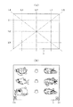
次に、遊技盤30の構成を図4に基づいて説明する。遊技盤30には、ルータ加工が施されることによって前後方向に貫通する大小複数の開口部が形成されている。各開口部には一般入賞口31、第1可変入賞装置32a、第2可変入賞装置32b、第1入球口としての第1作動口33a、第2作動口33b、スルーゲート34及び可変表示ユニット35等がそれぞれ設けられている。実際には、一般入賞口31、第1可変入賞装置32a、第2可変入賞装置32b、第1作動口33a、第2作動口33b、スルーゲート34及び可変表示ユニット35は木ねじ等により遊技盤表面に取り付けられている。本実施の形態では、可変表示ユニット35が遊技盤30の略中央に配置され、その下方に第1作動口33aが配置され、さらにその下方に可変入賞装置32aが配置されている。また、可変表示ユニット35の右側にスルーゲート34が配置され、遊技盤30の下部両側に一般入賞口31がそれぞれ複数配置されている。スルーゲート34の下方に第2作動口33bが配置されており、その第2作動口33bの左下方に第2可変入賞装置32bが配置されている。
Next, the structure of the
第2作動口33bには、左右一対の可動片よりなる電動役物33cが設けられている。その詳細を図5に示す。図5の(a)は電動役物33cが閉鎖状態(通常状態)にある場合を、(b)は電動役物33cが開放状態にある場合を図示している。電動役物33cが閉鎖状態にある場合には、電動役物33cの上端部と、第2作動口33bの上部に設けられた釘群40bとの間隔が遊技球の直径よりも僅かに短くなるよう設置間隔が調整されている。
The second working
上記構成によれば、電動役物33cの閉鎖状態では遊技球が第2作動口33bに入賞できず、電動役物33cが開放されることで第2作動口33bへの入賞が可能となる。つまり、電動役物33cが閉鎖状態の場合には、上方から落下してきた遊技球は、電動役物33cと第2作動口33bの上部に設けられた釘群40bとによってはじかれてしまい、第2作動口33bに直接入賞することはない。これにより、電動役物33cが極短時間で開放される場合には第2作動口33bへの入賞が極めて困難となり、電動役物33cの開放状態が継続される場合にのみ第2作動口33bへの入賞が容易となる。
According to the above configuration, in the closed state of the
前記一般入賞口31、各可変入賞装置32a,32b及び各作動口33a,33bに遊技球が入賞すると、それが後述する検出スイッチにより検出され、その検出結果に基づいて上皿23(場合によっては下皿16)に対し所定数の賞球が払い出される。また、第1作動口33aと第2作動口33bとでは、遊技球が入賞した場合に払い出される賞球数が相違するようになっており第1作動口33aに入賞した場合には3個の賞球が払い出され、第2作動口33bに入賞した場合には5個の賞球が払い出されるようになっている。
When a game ball wins in the general winning
その他に、遊技盤30の最下部にはアウト口36が設けられており、各種入賞口等に入らなかった遊技球はアウト口36を通って図示しない球排出路の方へと案内されるようになっている。アウト口36は、遊技盤30の下端略中央を逆U字状に切り欠いて形成されている。そのため、アウト口を穴状に形成していた従来構成に比べ、アウト口形成が容易となる(但し、図4では手前側にレールユニット50が重ねて設けられているため、アウト口36が閉じた状態で示されている)。また、遊技盤30には、遊技球の落下方向を適宜分散、調整等するために多数の釘が植設されていると共に、風車37等の各種部材(役物)が配設されている。
In addition, an
遊技盤30の左右両側部には、組付相手である本体枠12の左右両側からの張出領域との干渉を回避するように凹部としての切欠38が複数箇所に形成されている。
前述したとおり、本パチンコ機10では上皿23の位置を下げられており、それに伴い上皿23の最下流部に設けた遊技球の取込口の位置も同様に下げられている。この場合、遊技球取込口が比較的高い位置にあった従来構成では、遊技球取込口と遊技盤30とが前後に重なり、遊技盤30には遊技球取込口に対応する切欠を設ける必要があったが、本パチンコ機10では、遊技球取込口を下げたことにより遊技球取込口と遊技盤30とが前後に重なることがなく、遊技球取込口用の切欠の形成が不要となる。故に、遊技盤30の製作工程上、有利な構成となる。
As described above, in the
可変表示ユニット35には、各作動口33a,33bへの入賞をトリガとして図柄を変動表示する図柄表示装置41が設けられている。可変表示ユニット35には、図柄表示装置41を囲むようにしてセンターフレーム43が配設されている。このセンターフレーム43は、その上部がパチンコ機10前方に延出している。これにより、図柄表示装置41の表示画面の前方を遊技球が落下していくのが防止されており、遊技球の落下により表示画面の視認性が低下するといった不都合が生じない構成となっている。センターフレーム43の上部中央には、第1特定ランプ部47と第2特定ランプ部48が横並びの状態で設けられており、これら両特定ランプ部47,48に挟まれた位置に役物ランプ部49が設けられている。また、これらランプ部47〜49が配設された領域を挟むように、各特定ランプ部47,48及び図柄表示装置41に対応した保留ランプ44が設けられている。遊技球が各作動口33a,33bに入賞した個数はそれぞれ最大4個まで保留され、保留ランプ44の点灯によってその保留個数が表示されるようになっている。すなわち、第1作動口33aに遊技球が入賞した場合、第1特定ランプ部47の左方に設けられると共にこの第1特定ランプ部47と対応した第1保留ランプ44aが点灯され、第2作動口33bに遊技球が入賞した場合、第2特定ランプ部48の右方に設けられると共にこの第2特定ランプ部48と対応した第2保留ランプ44bが点灯されるようになっている。なお、両保留ランプ44a,44bが図柄表示装置41の一部で変動表示される構成等であっても良い。上述したように、センターフレーム43の上部がパチンコ機10前方に延出していることにより、保留ランプ44と各ランプ部47〜49の視認性が遊技球の落下により阻害されない構成となっている。センターフレーム43の下部には、役物ランプ部49に対応した役物保留ランプ46が設けられている。遊技球がスルーゲート34を通過した回数は最大4回まで保留され、役物保留ランプ46の点灯によってその保留個数が表示されるようになっている。なお、役物保留ランプ46は、図柄表示装置41の一部で変動表示される構成等であっても良い。
The
図柄表示装置41は8インチサイズの液晶ディスプレイを備えた液晶表示装置として構成されており、後述する表示制御装置により表示内容が制御される。図柄表示装置41には、例えば上、中及び下に並べて図柄が表示され、これらの図柄が左右方向にスクロールされるようにして変動表示されるようになっている。そして、予め設定されている有効ライン上に所定の図柄の組み合わせが停止表示された場合には、大当たり発生となると共にそれ以降の遊技状態が特別遊技状態としての大当たり状態に移行する。この図柄の変動表示については、後に詳細に説明することとする。なお、図柄表示装置41は、液晶表示装置の他に、CRT,ドットマトリックス,7セグメント等その他のタイプにより表示画面を構成したものであってもよい。
The
第1特定ランプ部47及び第2特定ランプ部48には、その内側に赤、緑、青の3色発光タイプのLEDが配設されている。各特定ランプ部47,48は、対応する作動口33a,33bへの入賞をトリガとして、所定の順序で発光色の切り替えが行われる。第1特定ランプ部47を例として具体的に説明すると、第1作動口33aへの入賞をトリガとして、赤色光が点灯され、その状態で所定時間が経過すると緑色光に発光色が切り替えられる。そして、緑色光が点灯された状態で前記所定時間が経過すると青色光に発光色が切り替えられる。その後、発光色の切り替え停止時期がくるまで、赤色、緑色、青色という順序で発光色の切り替えが繰り返し行われる。これにより、第1特定ランプ部47には、赤色、緑色、青色が、この順序で繰り返し表示されることとなる。そして、最終的に赤色が停止表示された場合には、大当たり発生としてそれ以降の遊技状態が大当たり状態に移行し、青色が停止表示された場合には、大当たり発生とならず大当たり状態に移行しない。第2特定ランプ部48についても同様であり、第2作動口33bへの入賞をトリガとして、赤色、緑色、青色が、この順序で繰り返し表示されることとなる。そして、最終的に赤色が停止表示された場合には、大当たり発生としてそれ以降の遊技状態が大当たり状態に移行し、青色が停止表示された場合には、大当たり発生とならず大当たり状態に移行しない。これら発光色の切り替えに関しては、後に詳細に説明することとする。
The first
一方、役物ランプ部49には、その内側に赤、緑の2色発光タイプのLEDが配設されている。この役物ランプ部49は、スルーゲート34の通過をトリガとして、所定の順序で発光色の切り替えが行われる。具体的には、遊技球がスルーゲート34を通過すると、赤色光の点灯と緑色光の点灯とが交互に行われる。これにより、役物ランプ部49には、赤色、緑色が交互に表示されることとなる。そして、赤色が停止表示された場合には、第2作動口33bに設けられた電動役物33cが開放状態に切り替えられるようになっている。電動役物33cは、予め定めた閉鎖条件が成立するまで開放状態が継続されるようになっている。なお、電動役物33cの閉鎖条件については後述することとする。
On the other hand, the
各可変入賞装置32a,32bは、通常状態において遊技球が入賞できない閉状態になっており、大当たり状態に移行すると遊技球が入賞しやすい所定の開放状態に切り替えられるようになっている。より詳しくは、各可変入賞装置32a,32bが開放状態となることによって、各可変入賞装置32a,32bに遊技球が入賞し易い状態となる。そして、第1可変入賞装置32aは、開放時間(例えば29.5秒)の経過又は所定数(例えば10個)の遊技球が入賞したことを閉鎖条件成立として閉状態に切り替えられる。大当たり状態は、各可変入賞装置32a,32bが開閉されたことを1ラウンドとして、所定ラウンド(例えば、15ラウンド)の開閉が行われるまで継続する。なお、各可変入賞装置32a,32bの閉状態を、各可変入賞装置32a,32bに遊技球が入賞できない状態ではなく遊技球が入賞し難い状態としてもよい。
Each of the
遊技盤30には、遊技球発射装置から発射された遊技球を遊技盤30上部へ案内するためのレール部材としてのレールユニット50が取り付けられており、遊技球発射ハンドル18の回動操作に伴い発射された遊技球はレールユニット50を通じて所定の遊技領域に案内されるようになっている。レールユニット50はリング状をなす樹脂成型品にて構成されており、より具体的には、摩擦抵抗を低減するべくフッ素配合のポリカーボネート樹脂が用いられている。レールユニット50は、内外二重に設けられた内レール部51と外レール部52とを有する。内レール部51は上方の約1/4ほどを除いて略円環状に形成され、外レール部52は内レール部51の上方開放領域を囲むようにかつ内レール51の左側部と並行するように略半円環状に形成されている。
A
内レール部51は、他の樹脂部分と一体成型され、遊技盤30の面上にほぼ垂直に起立して設けられている。また、外レール部52は、内レール部51と同様に他の樹脂部分と一体成型され、遊技盤30の面上にほぼ垂直に起立して設けられた支持部52aを有し、その支持部52aの内側面に、遊技球の飛翔をより滑らかなものとするための摺動プレート52bが取り付けられている。摺動プレート52bは、長尺状をなすステンレス製の金属帯よりなり、複数箇所で支持部52aに支持されている。かかる場合、内レール部51と外レール部52とにより誘導レールが構成され、これら各レール部51,52が所定間隔を隔てて対向する部分により球案内通路が形成されている。なお、内外のレール部51,52が対向する部位では、遊技盤30との当接部53により各レール部51,52が連結されており、球案内通路は手前側に開放した溝状に形成されている。
The
レールユニット50において、前記球案内通路より遊技球が飛び出す部位(図4の左上部)には戻り球防止部材54が取着され、該飛び出した遊技球の最大飛翔部分に対応する部位(図4の右上部)には返しゴム55が取着されている。戻り球防止部材54により、一旦球案内通路から遊技盤30の上部へと飛び出した遊技球が球案内通路内に戻ってしまうといった事態が防止される。また、所定以上の勢いで発射された遊技球は返しゴム55に当たり、遊技領域の中央寄りに跳ね返されるようになっている。
In the
レールユニット50の外周部には、外方へ張り出した円弧状のフランジ56が形成されている。フランジ56は、遊技盤30に対する取付面を構成する。レールユニット50が遊技盤30に取り付けられる際には、遊技盤30上にフランジ56が当接され、その状態で、当該フランジ56に形成された複数の透孔にネジ等が挿通されて遊技盤30に対するレールユニット50の締結がなされる。ここで、レールユニット50の上下及び左右の各端部は略直線状に形成されている。つまり、レールユニット50の上下及び左右の各端部においてはフランジ56が切り落とされ、パチンコ機10における有限の領域にてレール径の拡張、すなわち遊技盤30上の遊技領域の拡張が図られるようになっている。レールユニット50は、遊技盤30上の遊技領域の最大幅となる位置が遊技盤30の左右端位置に至るように配設されている。なお、レールユニット50の球案内通路に対応する部位のなかでも特に遊技球の受け入れ部位に関しては、当該レールユニット50を強固に取り付けて遊技球の飛びを安定させるべく、該当するフランジ56が他よりも多い箇所(本実施の形態では3カ所、他は2カ所)でネジ止めされている。
An arc-shaped
内レール部51及び外レール部52間の球案内通路の入口には、同球案内通路の一部を閉鎖するようにして凸部57が形成されている。凸部57は、内レール部51の外周部から下方へ延びるように形成され、遊技領域まで至らず球案内通路内を逆流してくるファール球をファール球通路76(図3参照)に導く機能を有する。遊技盤30の右下隅部及び左下隅部は、証紙等のシールやプレートを貼着するためのスペース(図のSa,Sb)となっており、この貼着スペースを確保するために、フランジ56に切欠58a,58bが形成されている。証紙等のシールを遊技盤30に直接貼り付ける構成とすることで、証紙等の不正な貼り直し等が行いにくいものとなっている。
A
遊技盤30においてレールユニット50よりも外方の左上部には、前後に貫通した中継端子孔59が設けられており、この中継端子孔59を通じて、遊技盤裏面に設置した中継端子板の接続コネクタ60がパチンコ機10前面側に露出されるようになっている。
In the
次に、遊技領域について説明する。遊技盤30の盤面はレールユニット50(内外レール部51,52)により内外領域に区画され、略円形状に区画された内側領域が遊技領域とされている。特に本実施の形態では、遊技盤30の盤面上に区画される遊技領域が従来よりもはるかに大きく構成されている。本実施の形態では、外レール部52の最上部地点から遊技盤30下部までの間の距離は445mm(従来品よりも58mm長い)、外レール部52の極左位置から内レール部51の極右位置までの間の距離は435mm(従来品よりも50mm長い)となっている。また、内レール部51の極左位置から内レール部51の極右位置までの間の距離は418mmとなっている。
Next, the game area will be described. The board surface of the
本実施の形態では、遊技領域を、パチンコ機10の正面から見て内レール部51及び外レール部52によって囲まれる領域のうち、内外レール部51,52の対向部分である球案内通路の領域を除いた領域として説明する。つまり、遊技領域は球案内通路部分を含まないため、遊技領域の向かって左側限界位置は外レール部52によってではなく内レール部51によって特定される。また、遊技領域の向かって右側限界位置は内レール部51によって特定され、遊技領域の下側限界位置はアウト口36が形成された遊技盤30の下端位置によって特定され、遊技領域の上側限界位置は外レール部52によって特定される。従って、本実施の形態では、遊技領域の幅(左右方向の最大幅)は、418mmであり、遊技領域の高さ(上下方向の最大幅)は、445mmである。
In the present embodiment, the game area is an area of a ball guide passage that is an opposite part of the inner and
本実施の形態では、遊技盤30面に対する遊技領域の面積の比率は約70%と、従来に比べ格段に面積比が大きいものとなっている。なお、遊技盤30面に対する遊技領域の面積比は、従来では50%程度に過ぎなかったことから、本実施の形態のように従来と同様の大きさの遊技盤30を使用している前提下では相当に遊技領域を拡大しているといえる。なお、パチンコ機10の外形は遊技ホールへの設置の都合上製造者間でほぼ統一されており、遊技盤30の大きさも同様とせざるを得ない状況下において、上記のように遊技盤30面に対する遊技領域の面積の比率を約20%も高めたことは、遊技領域拡大の観点で非常に有意義である。
In the present embodiment, the ratio of the area of the game area to the surface of the
遊技領域の拡張に関連して、可変表示ユニット35の右側に位置するスルーゲート34は、該ゲート34を通過した遊技球が第2可変入賞装置32bの方へ寄せられるような案内機構(本実施の形態では、主に遊技盤に30に配された釘によって案内機構を構成している)を有している。また、スルーゲート34を通過した遊技球は、釘群40aによって第1作動口33a及び第1可変入賞装置32aの方に寄せられないように設定されている。具体的には、第2作動口33b及び第2可変入賞装置32bに遊技球が入賞するよう遊技を行った場合には、第2作動口33b及び第2可変入賞装置32bに入賞するよう釘群40aが案内機構として機能する。さらに、第1作動口33a及び第1可変入賞装置32aに遊技球が入賞しないよう釘群40aが障害釘として機能する。
In connection with the expansion of the game area, the through
詳細は後述するが本実施の形態では、第1作動口33aに遊技球が入賞するよう遊技を行う場合と、第2作動口33bに遊技球が入賞するよう遊技を行う場合がある。スルーゲート34を通過した遊技球が第1作動口33a及び第1可変入賞装置32aの方に寄せられないように設定されていることは、第2作動口33bに遊技球が入賞するように遊技を行う場合に、第1作動口33aに遊技球が寄せられてしまうことを抑制するための工夫である。
Although details will be described later, in the present embodiment, there is a case where a game is played so that a game ball wins the
遊技盤30の左右両側部に切欠38が形成されて本体枠12の左右両側からの張出領域との干渉が回避されていること、レールユニット50において遊技盤30上の遊技領域の最大幅となる位置が遊技盤30の左右端位置にまで至るようになっていることは既に述べたが、更に後述するように、本体枠12の左右両側部に設けられる補強部材(軸受け金具235:図10参照)と施錠装置(基枠247、連動杆248等:図10参照)とを配置するための領域を残した幅となるようにして本体枠12に遊技盤30が取り付けられている。これらのことからも、遊技領域の拡張が図られている。
図3の説明に戻り、前記樹脂ベース25において、窓孔26(遊技盤30)の下方には、遊技球発射装置より発射された直後に遊技球を案内するための発射レール61が取り付けられている。発射レール61は、その後方の金属板62を介して樹脂ベース25に取付固定されており、所定の発射角度(打ち出し角度)にて直線的に延びるよう構成されている。従って、遊技球発射ハンドル18の回動操作に伴い発射された遊技球は、まずは発射レール61に沿って斜め上方に打ち出され、その後球案内通路を通じて遊技領域に案内される。前述のとおり遊技領域が従来よりも大幅に拡張されたことにより、球案内通路の曲率は小さくなっているため、打出球を安定化させるための工夫が必要となる。そこで、本実施の形態では、遊技球の発射位置を低くして発射レール61の傾斜角度(発射角度)を既存のものよりも幾分大きくし(すなわち発射レール61を立ち上げるようにし)、また発射レール61を遊技球発射装置の発射位置から遊技領域の中央位置(アウト口36)を越える位置まで延びるよう形成することで発射レール61の長さを既存のものよりも長くして十分な長さの球誘導距離を確保するようにしている。これにより、遊技球発射装置から発射された遊技球をより安定した状態で球案内通路に案内できるようにしている。さらに打出球の安定化を図るべく、発射レール61を設置した金属板62を大型化すると共に該金属板62を多数箇所(本実施の形態では15〜20カ所)でネジ止めしており、これにより発射レール61が遊技盤30に対して強固に位置決めされている。
Returning to the description of FIG. 3, in the
発射レール61と球案内通路との間には所定間隔の隙間があり、この隙間より下方にファール球通路76が設けられている。従って、仮に遊技球発射装置から発射された遊技球が戻り球防止部材54まで至らずファール球として球案内通路内を逆戻りする場合には、そのファール球がファール球通路76を介して下皿16に排出される。
There is a predetermined gap between the firing
ファール球が球案内通路内を逆流してくる際、その多くは外レール部52に沿って流れ、外レール部52の下端部に到達した時点で下方に落下するが、一部のファール球は球案内通路内で暴れ、内レール部51側へ跳ね上がるものもある。この際、跳ね上がったファール球は、球案内通路入口の前記凸部57に当たり、ファール球通路76に誘導される。これにより、ファール球の全てがファール球通路76に確実に案内され、ファール球と次に発射される遊技球との干渉が抑制される。
When the foul balls flow backward in the ball guide passage, most of them flow along the
なお、詳しい図面の開示は省略するが、遊技球発射装置には、前扉枠13側の球出口(上皿23の最下流部より通じる球出口)から遊技球が1つずつ供給される。この際、本実施の形態では遊技球の発射位置を低くしたため、前扉枠13側の球出口から前記発射位置への落差が大きくなるが、発射レール61の発射基端部付近にはその右側と手前側にそれぞれガイド部材63,64を設置してある。これにより、前扉枠13側の球出口から供給される遊技球が常に所定の発射位置にセットされ、安定した発射動作が実現できる。また、遊技球発射装置には、基端部を中心に回動可能に支持された打球槌が設けられ、打球槌の回動に伴い遊技球が発射されるが、打球槌に関して軽量化が望まれている。それ故、アルミニウム等の軽金属への材料変更や槌シャフト部寸法の縮小化により打球槌の軽量化を図る一方で、十分な発射力を確保すべく、打球槌のヘッド部(基端部と反対側の先端部)に重り部を設けている。これにより、十分でかつ安定した遊技球の発射が実現できる。打球槌の重り部を上方に突出して設けることにより、打球槌を容易に摘んだりひっかけたりすることができ、槌先の打球強さの調整等がし易くなるという効果も得られる。
Although detailed disclosure of the drawings is omitted, one game ball is supplied to the game ball launching device one by one from the ball outlet on the
また、本体枠12の前面において発射レール61の左側には、左右一対の排出口66,67が形成されると共に、その前方に、排出口66,67より排出された遊技球を上皿23又は下皿16のいずれかに案内するための遊技球案内ユニット70が取り付けられている。便宜上以下の説明では、排出口66を第1排出口、排出口67を第2排出口ともいう。これら排出口66,67は、本体枠12の背面に設けられた遊技球分配部245(図11参照)に通じており、基本的に第1排出口66より遊技球の排出が行われ、この第1排出口66も含め上皿23に通じる通路が遊技球で一杯になると、第1排出口66に代えて第2排出口67より遊技球の排出が行われるようになっている。
In addition, a pair of left and right discharge ports 66 and 67 are formed on the left side of the
遊技球案内ユニット70は、ポリカーボネート樹脂等の透明な樹脂材料により内部を視認可能に構成され、本体枠12に対して前扉枠13を閉鎖した状態で本体枠12と前扉枠13との間に収まるよう厚みが比較的薄くなるように形成されている。遊技球案内ユニット70には、前述のファール球通路76が一体的に形成されている。遊技球案内ユニット70には、前記排出口66,67と下皿16とを連通するための球排出通路71が形成されている。遊技球案内ユニット70には、本体枠12の第1排出口66の手前側に、上皿23に連通する連通口72が形成され、連通口72を閉鎖するようにして開閉プレート73が取り付けられている。開閉プレート73は支軸74により回動可能に支持され、付勢手段としてのバネ75により連通口72を閉鎖する位置に常時付勢されている。
The game
遊技球案内ユニット70の上記構成によれば、前扉枠13を開放した状態ではバネ75の付勢力により開閉プレート73が図示の如く起き上がり、連通口72を閉鎖する。この状態では、第1排出口66より排出される遊技球が球排出通路71を通じて下皿16に案内される。従って、連通口72の上流側に遊技球が貯留されている状態で前扉枠13を開放した場合、その貯留球は連通口72よりこぼれ落ちることなく、球排出通路71を通じて下皿16に流下する。つまり、前飾り枠が省略され前扉枠13に対して上皿23が直接設けられる構成とした本パチンコ機10にあっても、前扉枠13の開放に際し連通口72の上流側にある遊技球がこぼれ落ちてしまうといった不都合が防止できる。これに対し、前扉枠13を閉鎖した状態では、前扉枠13の裏面に設けられた球通路樋138(図2参照)によりバネ75の付勢力に抗して開閉プレート73が押し開けられる。この状態では、第1排出口66より排出される遊技球が連通口72を介して上皿23に案内される。従って、連通口72より上流側の遊技球は上皿23に払い出される。なお、遊技球案内ユニット70の球排出通路71下流側には、下皿16に排出された遊技球が一杯(満タン)になったことを検知する下皿満タンスイッチが取り付けられている。
According to the above configuration of the game
樹脂ベース25には、窓孔26の右下部に略四角形状の小窓78が設けられている。従って、遊技盤30の右下隅部スペース(図4のSa)に貼られた証紙等は、この小窓78を通じて視認できるようになっている。この小窓78から遊技盤30上に証紙等を直接貼り付けることも可能である。
The
樹脂ベース25には、窓孔26の左上部にも小窓79が設けられている。この小窓79は、図4で説明した遊技盤30の中継端子孔59に対応する位置にそれとほぼ同一の形状で設けられ、中継端子孔59及び小窓79を通じて、遊技盤裏面に設置した中継端子板の接続コネクタ60が本体枠12の前面側に露出される。かかる構成において、前扉枠13側に設けた各種ランプに対しては、本体枠12(樹脂ベース25)の小窓79より露出した接続コネクタ60を介して電気的な接続がなされている。樹脂ベース25の上部には、前扉枠13の開放の状態を検出するための前扉枠開放スイッチ27が設けられている。前扉枠開放スイッチ27は、樹脂ベース25の前面に出没可能なピンを有しており、本体枠12に対して前扉枠13を閉じた状態ではピンが押し込まれて前扉枠13の閉鎖が検知され、本体枠12に対して前扉枠13を開いた状態ではピンが突出位置に戻って前扉枠13の開放が検知されるようになっている。樹脂ベース25の左右2カ所には、本体枠12に対して前扉枠13を閉じた際に前扉枠13背面の金具類(図6に示す補強板131〜134)に接触し、且つその金具類を本体枠12側に導通させてアース(接地)するための金属片28a,28bが取り付けられている。従って、金属片28a,28bを通じて、前扉枠13背面の金具類が本体枠12側の施錠装置やヒンジ金具に導通され、これら施錠装置やヒンジ金具と共にアースされる。
A
本体枠12の左端側(開閉軸線側)には、前扉枠13を開閉可能に支持するための支持機構として、上下一対の支持金具81,82が取り付けられている。上側の支持金具81には手前側に切欠を有する支持孔83が設けられ、下側の支持金具82には上方へ突出する突起軸84が設けられている。なお、支持金具81,82に支持される前扉枠13の具体的構成については後述する。また、本体枠12の右端側(開閉軸線とは反対側)には、前扉枠13裏面側の開放端側に設けた上下一対の鉤金具155,156(図2参照)を挿入するための挿入孔87,88がそれぞれ設けられている。本パチンコ機10では、本体枠12や前扉枠13を施錠状態とするための施錠装置が本体枠12の裏面側に隠れて配置される構成となっている。従って、鉤金具155,156が挿入孔87,88を介して施錠装置に係止されることによって、前扉枠13が本体枠12に対して開放不能に施錠される。
A pair of upper and
本体枠12の右下隅部には、外枠11に対する本体枠12の施錠及び解錠、並びに本体枠12に対する前扉枠13の施錠及び解錠を行うための鍵部材としてのシリンダ錠91が設置されている。シリンダ錠91は施錠装置に一体化されており、施錠装置のうちシリンダ錠91だけが本体枠12の前方に突出した状態で設けられている。この場合、シリンダ錠91は、遊技領域の最大幅となる位置とは異なる位置に設けられている。シリンダ錠91は、本体枠12の施解錠と前扉枠13の施解錠とを共に賄う機能を有しており、鍵穴に差し込んだキーを左(反時計回り方向)に回すと本体枠12の施錠が解かれ、逆にキーを右(時計回り方向)に回すと前扉枠13の施錠が解かれるようになっている。
A
図2に示すように、本体枠12には、シリンダ錠91を囲むようにして縦長状のカバー部材92が取り付けられている。詳細な図示は省略するが、カバー部材92には、その上端部及び下端部に係止部(フック)が形成されている。従って、上側の係止部を本体枠12側に係止させると共に、下側の係止部を本体枠12と前面板14との間に挟み込むことにより、カバー部材92が本体枠12に取り付けられる。前扉枠13には、カバー部材92の形状に合わせて切欠部145が形成されており、前扉枠13を閉鎖した状態ではこの前扉枠13と共にカバー部材92がパチンコ機前面部を構成する。なお、前扉枠13を閉鎖したとき、カバー部材92に形成された鍔部が前扉枠13により押さえられ、カバー部材92のがたつきが防止されるようになっている。
As shown in FIG. 2, a vertically
次に、前扉枠13について図1,図6を参照しつつ説明する。なお、図6は、前扉枠13の背面図である。
Next, the
前扉枠13には遊技領域のほぼ全域を前方から視認することができるようにした視認窓としての窓部101が形成されている。窓部101は、円形に近い略楕円形状をなし、より詳しくは、その左右側の略中央部が上下側に比べて緩やかに湾曲した形状となっている。なお、前記略中央部が直線状になる形状であってもよい。前扉枠13の窓部101上方において、最も狭い部位のフレーム幅は約61mmである。本実施の形態における上記フレーム幅寸法は、本体枠12において外レール部52の最上部(遊技領域の上端)と本体枠12の上端との間の距離とほぼ一致するものであって、85mm〜95mm程度の上記フレーム幅を有する従来機種に比べて著しく短くなっている。これにより、遊技領域における上部領域の視認性が確保されやすくなると共に、大型の可変表示ユニット35も比較的上方に配置することができるようになっている。窓部101上方のフレーム幅(最狭部位)の寸法は80mm以下であることが望ましく、より望ましくは70mm以下であり、さらに望ましくは60mm以下である。もちろん、所定の強度が確保できるのであれば、50mm以下としても差し支えない。
The
前扉枠13の左右のフレーム部分は、フレーム幅を小さくするには制約があり、前扉枠13自体の強度及びガラス支持強度を確保するのに十分な幅寸法を必要とする。本実施の形態では、左右の各フレーム部分において最も狭い部位のフレーム幅を何れも約44mmとしている。この場合、本パチンコ機10にあっては遊技領域を大幅に拡張したことから、パチンコ機10の正面から見て左側すなわち開閉軸線側では、前扉枠13のフレーム幅が上記の通り約44mmとなるのに対し、レールユニット50の外レール部52の左端位置と本体枠12の左端位置との距離が約21mmとなり、後者の寸法がかなり小さいものとなっている。つまり本構成では、前扉枠13を閉鎖した状態において、球案内通路の一部が、前扉枠13の左側フレーム部分と重複し覆い隠されるようになる。しかしながら、球案内通路において遊技球が一時的に視認困難となったとしても、かかる球案内通路は遊技球が遊技領域に案内されるまでの通過領域に過ぎず、遊技者が主として遊技を楽しむ遊技領域において遊技球が視認困難となるわけではない。そのため、実際の遊技に際しては何ら支障が生じない。以上により、前扉枠13の十分な強度及びガラス支持強度を確保しつつも、遊技に何ら支障を及ぼすことなく遊技領域の拡張が可能となる。
The left and right frame portions of the
前扉枠13の下端部における左右両側には、本体枠12表面や遊技盤30表面等(証紙等を含む)の一部を視認できるよう透明樹脂を取り付けた小窓107が設けられている。小窓107に取り付けられる透明樹脂は、その内部の証紙等を工場等で容易に機械読み取りできるよう平坦状に構成される。但し、小窓107に、内部の証紙等をホール作業者等が容易に目視できるよう拡大レンズ部を設けることも可能である。
前扉枠13にはその周囲(例えばコーナー部分)に各種ランプ等の発光手段が設けられている。これら発光手段は、大当たり状態下や所定のリーチ演出時等において点灯、点滅のように発光態様が変更制御されることにより、遊技中の演出効果を高める役割を果たす。例えば、窓部101の周縁に沿ってLED等の発光手段を内蔵した環状電飾部102が左右対称に設けられ、環状電飾部102の中央であってパチンコ機10の最上部にはLED等の発光手段を内蔵した中央電飾部103が設けられている。本パチンコ機10では、中央電飾部103が大当たりランプとして機能し、大当たり状態下で点灯や点滅を行うことにより大当たり状態に移行していることを報知する。また、上皿23周りにも、同じくLED等の発光手段を内蔵した上皿電飾部104が設けられている。その他、中央電飾部103の左右側方には、賞球払出中に点灯する賞球ランプ105と所定のエラー時に点灯するエラー表示ランプ106とがそれぞれ設けられている。なお、環状電飾部102は、内外二重の樹脂カバー層とその内側に収容された発射板付き発光体(LED)とよりなり、樹脂カバー層の各々の内側面には各層で縦横に交差する向きに突条(又は波状の突起)が設けられている。外側の樹脂カバー層は透明であり、内側の樹脂カバー層は有色である。従って、環状電飾部102を発光させれば、多数に分散化された状態、又は立体感を伴った状態の電飾が実現できるようになる。樹脂カバー層には、ガラス粉末入りの樹脂材料を用いると良い。このような樹脂カバー層の構成は、他の電飾部(例えば中央電飾部103や賞球ランプ105)に適用することもできる。
The
前扉枠13には、窓部101の下方位置に、貸球操作部120が配設されている。貸球操作部120には球貸しボタン121と、返却ボタン122と、度数表示部123とが設けられている。パチンコ機10の側方に配置されたカードユニット(球貸しユニット)に紙幣やカード等を投入した状態で、貸球操作部120によって球貸し操作、カード返却操作及びカード度数の確認を行うことができる。すなわち、球貸しボタン121は、カード等(記録媒体)に記録された情報に基づいて貸出球を得るために操作されるものであり、カード等に残額が存在する限りにおいて貸出球が払い出される。返却ボタン122は、カードユニットに挿入されたカード等の返却を求める際に操作される。度数表示部123はカード等の残額情報を表示するものである。なお、カードユニットを介さずに球貸し装置等から上皿に遊技球が直接貸し出されるパチンコ機(いわゆる現金機)では貸球操作部120が不要となるが、かかる場合には、貸球操作部120の設置部分に飾りシール等が付されるようになっている。これにより、貸球操作部120を設けた本パチンコ機10の構成において、カードユニットを用いたパチンコ機(いわゆるCR機)と現金機との共用が可能となる。
The
前扉枠13の裏側には、窓部101を囲むようにして金属製の各種補強部材が設けられている。詳しくは、図6に示すように、前扉枠13の裏側にあって窓部101の左右及び上下の外側にはそれぞれ補強板131,132,133,134が取り付けられている。これら補強板131〜134は相互に接触して連結されているが、図の左側及び上側の補強板132,133の連結部には直接の接触を避けるための樹脂パーツ135が介在されている。これにより、補強板131〜134による電気経路の閉じたループが切断され、ノイズの原因となる磁界の発生等が防止されている。
On the back side of the
図6の右側となる開閉軸線側の補強板131にはその上端部及び下端部に、本体枠12に対する組付機構として、組付金具151,152が取り付けられている。そして、本体枠12側の支持金具81,82(図3参照)に対して前扉枠13側の組付金具151,152が取り付けられている。すなわち、下側の組付金具152には下面に開口する軸穴が形成されており、その軸穴に下側の支持金具82の突起軸84が挿入される一方、上側の組付金具151の軸部が上側の支持金具81の支持孔83に挿入されることにより、本体枠12に対して前扉枠13が開閉可能に支持されている。また、同補強板131にはその中間位置にフック状をなす係合爪131aが設けられており、この係合爪131aは、前扉枠13を閉じた状態で本体枠12の孔部12a(図3参照)に挿入されるように構成されている。これにより、上皿23を含む形態で前扉枠13を構成し、その上下の軸支間隔を長くした本パチンコ機10においても、中間位置における前扉枠13の浮き上がりが防止できる。それ故、前扉枠13を浮かしての不正行為等が抑制されるようになっている。
As shown in the right side of FIG. 6, the mounting
図6の左側となる開閉軸線とは反対側の補強板132には鉤形状をなす上下一対の鉤金具155,156が取り付けられている。これら鉤金具155,156は、後方に延び、本体枠12に設けた挿入孔87,88(図3参照)に対応するようにして設けられている。本体枠12に対して前扉枠13を閉鎖した際、鉤金具155,156が本体枠12側の挿入孔87,88に挿入されて施錠装置により施錠状態とされるようになっている。
A pair of upper and
下側の補強板134には、前記発射レール61に対向する位置に樹脂ケース136が取り付けられている。樹脂ケース136には、前記貸球操作部120用の回路基板が収容されている。樹脂ケース136の背面(図6に見える面)は平坦状をなし、前扉枠13を閉じた際に発射レール61の側壁を構成するようになっている。故に、発射レール61から遊技球が前方にこぼれ落ちることが防止される。
A
下側の補強板134の一部を切り欠いた部位には、パチンコ機10後方に向けて球通路樋138が設置されており、球通路樋138の少なくとも上方には、同じくパチンコ機10後方に向けて延びる庇(ひさし)部139が設けられている。この場合、本体枠12側に前扉枠13を閉じた状態では、球通路樋138と庇部139との間に、本体枠12側の連通口72上辺に沿って延びる突条が入り込むようにして配置される。故に、球通路樋138より針金やフィルム等を侵入させて不正行為を行おうとしても、遊技領域にまで針金やフィルム等を侵入させることが非常に困難となる。結果として、針金やフィルム等を利用して行われる不正行為を防止することができる。
A
上述した補強板131〜134はガラス支持用の金枠としての機能も兼ね備えており、これら補強板131〜134の内側が後方に折り返されてガラス保持溝が形成されている。ガラス保持溝は前後に2列形成されており、矩形状をなす前後一対のガラス137が各ガラス保持溝にて保持される。これにより、2枚のガラス137が前後に所定間隔を隔てて取着されている。
The reinforcing
前述した通り本実施の形態のパチンコ機10では遊技領域の拡張を図っていることから、前扉枠13を閉じた状態にあっては、内外のレール部51,52間に形成された球案内通路の一部が前扉枠13により覆い隠される構成となっている。それ故、球案内通路では手前側の開放部がガラス137で覆えない部分ができてしまう。かかる場合、例えば、遊技球発射装置より発射された遊技球が戻り球防止部材54まで至らず戻ってくると、遊技球が球案内通路外に飛び出したり、外レール部52とガラス137との間にできる隙間に挟まってしまうおそれがある。そこで本実施の形態では、前扉枠13に、球案内通路の手前側開放部を被覆するためのレールカバー140を取り付けている。レールカバー140は略円弧状をなす板体であって、透明な樹脂により形成されている。レールカバー140は、その円弧形状が前記球案内通路の形状に対応しており、窓部101の周縁部に沿って、球案内通路の基端部から先端部近傍までの区間を覆うようになっている。特にレールカバー140の内径側の寸法・形状は内レール部51のそれにほぼ一致する。また、レールカバー140の右端部(すなわち、レールカバー140を前扉枠13に取着した図6の状態で右端となる部位)には、球案内通路がガラス137の側縁部からはみ出した部分を被覆するための被覆部141が設けられている。以上のレールカバー140の構成により、前扉枠13が閉じられた状態においては、レールカバー140の裏面が球案内通路のほぼ全域を覆うこととなって、遊技球が球案内通路外に飛び出したり、外レール部52とガラス137との間にできる隙間に挟まってしまうといった不具合の発生を防止することができる。
As described above, in the
また、レールカバー140の下部裏側には、その内側縁に沿って円弧状に延び且つ後方へ向けて突出する突条142が形成されている。突条142は、前扉枠13が閉じられた状態において、球案内通路内に入り込んだ状態で内レール部51に重なり合うように配置される。従って、例えば前扉枠13と本体枠12との隙間から針金やフィルム等を侵入させて不正行為を行おうとしても、球案内通路の内側にある遊技領域にまで針金やフィルム等を侵入させることが非常に困難となる。その結果、針金やフィルム等を利用して行われる不正行為を防止することができる。なお、突条142をより広い範囲で、例えばレールカバー140の内側縁の全域に沿って形成する構成としても良く、かかる構成によれば、より広い範囲で針金やフィルム等を侵入させにくくなり、針金やフィルム等を利用して行われる不正行為をより確実に防止することができる。
Further, on the lower back side of the
次に、パチンコ機10の背面の構成を説明する。なお、図7はパチンコ機10の背面図、図8はパチンコ機10の背面構成を主要部品毎に分解して示す分解斜視図である。
Next, the configuration of the back surface of the
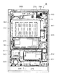
まず、パチンコ機10の背面構成について全体の概要を説明する。パチンコ機10の背面側には、各種制御装置(各種制御基板)が上下左右に並べられるようにして又は前後に重ねられるようにして配置されるとともに、遊技球を供給するための遊技球供給装置(払出機構)や樹脂製の保護カバー等が取り付けられている。本実施の形態では、各種制御装置を2つの取付台に分けて搭載して2つの制御基板ユニットを構成し、それら制御基板ユニットを個別に本体枠12又は遊技盤30の裏面に装着するようにしている。この場合、主制御装置271(主基板)と音声ランプ制御装置272(音声ランプ制御基板)とを一方の取付台に搭載してユニット化すると共に、払出制御装置311(払出制御基板)、発射制御装置312(発射制御基板)及び電源装置313(電源基板)を他方の取付台に搭載してユニット化している。以下においては、便宜上、前者のユニットを「第1制御基板ユニット201」と称し、後者のユニットを「第2制御基板ユニット202」と称することとする。また、払出機構及び保護カバーも1ユニットとして一体化され、一般に樹脂部分を裏パックと称することもあるため、ここではそのユニットを「裏パックユニット203」と称する。各ユニット201〜203の詳細な構成については後述する。
First, an overall outline of the rear configuration of the
第1制御基板ユニット201、第2制御基板ユニット202及び裏パックユニット203は、ユニット単位で何ら工具等を用いずに着脱できるよう構成されるとともに、一部に支軸部を設けて本体枠12又は遊技盤30の裏面に対して展開できる構成となっている。これは、各ユニット201〜203やその他構成が前後に重ねて配置された場合に隠れた部位を容易に確認することを可能とするための工夫でもある。実際には、図9の概略図に示すように、略L字状をなす第1制御基板ユニット201はパチンコ機10のほぼ中央に配置され、その下方に第2制御基板ユニット202が配置されている。また、第1制御基板ユニット201に一部重複する領域に、裏パックユニット203が配置されている。
The first
第1制御基板ユニット201にはパチンコ機10の背面から見て左端部に支軸部M1が設けられ、その支軸部M1による軸線Aを中心に第1制御基板ユニット201が回動可能となっている。また、第1制御基板ユニット201には、その右端部すなわち支軸部M1の反対側となる開放端側に、ナイラッチ(登録商標)等よりなる締結部M2が設けられると共に上端部に係止爪部M3が設けられており、これら締結部M2及び係止爪部M3によって第1制御基板ユニット201がパチンコ機10本体の裏面に沿った状態に保持されるようになっている。また、第2制御基板ユニット202にはパチンコ機10の背面から見て右端部に支軸部M4が設けられ、その支軸部M4による軸線Bを中心に第2制御基板ユニット202が回動可能となっている。また、第2制御基板ユニット202には、その左端部すなわち支軸部M4の反対側となる開放端側に、ナイラッチ等よりなる締結部M5が設けられており、この締結部M5によって第2制御基板ユニット202がパチンコ機10本体の裏面に沿った状態に保持されるようになっている。さらに、裏パックユニット203にはパチンコ機10の背面から見て右端部に支軸部M6が設けられ、その支軸部M6による軸線Cを中心に裏パックユニット203が回動可能となっている。また、裏パックユニット203には、その左端部すなわち支軸部M6の反対側となる開放端側にナイラッチ等よりなる締結部M7が設けられるとともに、上端部及び下端部にそれぞれ回動式の係止部M8,M9が設けられており、これら締結部M7及び係止部M8,M9によって裏パックユニット203がパチンコ機10本体の裏面に沿った状態に保持されるようになっている。
The first
各ユニット201〜203を回動可能に支持する支軸部M1,M4,M6は、各ユニット201〜203をパチンコ機10の裏面から開いた状態で容易に取り外し可能なヒンジ構造となっている。簡単に説明すると、第1制御基板ユニット201については、締結部M2の締結及び係止爪部M3の係止を解除すると共に、当該ユニット201を軸線Aを中心に回動させて展開し、その状態で持ち上げる。これにより、裏パックユニット203がない前提であれば、第1制御基板ユニット201を取り外すことができる。また、第2制御基板ユニット202については、締結部M5の締結を解除すると共に、当該ユニット202を軸線Bを中心に回動させて展開し、その状態で持ち上げる。これにより、第2制御基板ユニット202を取り外すことができる。さらに、裏パックユニット203については、締結部M7の締結及び係止部M8,M9の係止を解除すると共に、当該ユニット203を軸線Cを中心に回動させて展開し、その状態で持ち上げる。これにより、裏パックユニット203を取り外すことができる。
The support shaft portions M1, M4, and M6 that rotatably support the
ここで、各ユニット201〜203の展開方向は同一でなく、第1制御基板ユニット201は、パチンコ機10の背面から見て左開きになるのに対し、第2制御基板ユニット202及び裏パックユニット203は、同右開きになるよう構成されている。この場合、第1制御基板ユニット201は、裏パックユニット203に一部重複して設けられるため、裏パックユニット203を開かないことには第1制御基板ユニット201を取り外すことが不可能であり、さらに言うと、第1制御基板ユニット201及び裏パックユニット203が各々逆方向に展開する構成であるため、裏パックユニット203を所定角度以上に大きく開いた状態又は同ユニット203を取り外した状態でなければ第1制御基板ユニット201を取り外すことが不可能である。従って、第1制御基板ユニット201を取り外すことに着目すると、他のユニット202,203に比べて取り外しが困難な構成となっている。さらに、施錠装置をキー操作して外枠11に対して本体枠12を開放しなければ、裏パックユニット203を開くことができない構成となっているため、より一層第1制御基板ユニット201の取り外しが困難なものとなっている。より具体的な構成については後述する。
Here, the development directions of the
次に、本体枠12及び遊技盤30の裏面構成を説明する。なお、図10は本体枠12に遊技盤30を組み付けた状態でかつ前記各ユニット201〜203等を取り外した状態の構成を示す背面図、図11は本体枠12を後方より見た斜視図、図12は遊技盤30を後方より見た斜視図である。
Next, the back surface structure of the
遊技盤30は、樹脂ベース25に囲まれた四角枠状の設置領域に裏面側より設置され、本体枠12に設けられた複数(本実施の形態では4カ所)の係止固定具211,212によって後方へ脱落しないように固定されている。係止固定具211,212は手動で回動操作することができ、固定位置(ロック位置)と固定解除位置(アンロック位置)とに切り替えることができるよう構成されている。図10にはロック状態を示す。左右3カ所の係止固定具211は金属片を折り曲げ形成したL型の金具であり、遊技盤30の固定状態で本体枠12の外方へ張り出さないよう構成されている。なお、下部1カ所の係止固定具212は合成樹脂製のI型の留め具である。
The
遊技盤30の中央に配置される可変表示ユニット35には、センターフレーム43(図4参照)を背後から覆う合成樹脂製のフレームカバー213が後方に突出して設けられており、そのフレームカバー213の後端に、図柄表示装置41と表示制御手段としての表示制御装置214とが前後に重ねられた状態で着脱可能に取り付けられている。フレームカバー213内には、センターフレーム43に内蔵されたLED等を駆動するためのLED制御基板などが配設されている。
The
遊技盤30の裏面には、可変表示ユニット35を取り囲むようにして集合板ユニット215が設けられている。集合板ユニット215は、薄板状の枠体として例えばABS樹脂等の合成樹脂により成形されるベースを有し、そのベース面が遊技盤30の裏面に当接されるようにして取り付けられている。集合板ユニット215には、各種入賞口に入賞した遊技球を回収するための遊技球回収機構や、各種入賞口等への遊技球の入賞を検知するための入賞検知機構などが設けられている。
A
遊技球回収機構について説明すると、集合板ユニット215の下方には、前記一般入賞口31、各可変入賞装置32a,32b、各作動口33a,33bの遊技盤開口部に対応し且つ下流側で1カ所に集合する回収通路216が形成されている。また、遊技盤30の下方には、本体枠12にポリカーボネート樹脂等の合成樹脂製の排出通路盤217が取り付けられており、排出通路盤217には排出球をパチンコ機10外部の例えば遊技ホールの島設備等へ案内するための排出通路218が形成されている。従って、図10に仮想線で例示するように、一般入賞口31等に入賞した遊技球は何れも集合板ユニット215の回収通路216を介して集合し、さらに排出通路盤217の排出通路218を介してパチンコ機10外部に排出される。なお、アウト口36も同様に排出通路218に通じており、何れの入賞口にも入賞しなかった遊技球も排出通路218を介してパチンコ機10外部に排出される。上記構成では、遊技盤30の下端面を境界にして、上方に集合板ユニット215(回収通路216)が、下方に排出通路盤217(排出通路218)が設けられており、排出通路盤217が遊技盤30に対して前後方向に重複していない。従って、遊技盤30を本体枠12から取り外す際において、排出通路盤217が遊技盤取り外しの妨げになるといった不都合が生じることもない。
The game ball collecting mechanism will be described. Below the
なお、排出通路盤217は、パチンコ機10前面の上皿23の裏側に配置されており、上皿23に至る球排出口(図2の球通路樋138)より針金やフィルム等を差し込み、さらにその針金やフィルム等を本体枠12と排出通路盤217との隙間を通じて遊技領域側に侵入させるといった不正行為が考えられる。そこで、本パチンコ機10では、図11に示すように、排出通路盤217には、球通路樋138の上部位置に対応する高さ位置に、本体枠12に重なり合うようにしてパチンコ機10前方に延びるプレート219を設けた。従って、本体枠12と排出通路盤217との隙間から針金やフィルム等を侵入させようとしてもそれがプレート219にて阻害され、遊技領域にまで針金やフィルム等を侵入させることが非常に困難となる。その結果、針金やフィルム等を利用して各可変入賞装置32a,32bを強制的に開放する等の不正行為を防止することができる。
The
入賞検知機構について説明すると、図10に示すように、集合板ユニット215には、遊技盤30表側の一般入賞口31と対応する位置に入賞口スイッチ221が設けられ、各可変入賞装置32a,32bとそれぞれ対応する位置にカウントスイッチ223a,223bが設けられている。各カウントスイッチ223a,223bは、各可変入賞装置32a,32bに入賞した遊技球の数をカウントするスイッチである。また、各作動口33a,33bにおける第1作動口33aと対応する位置には当該第1作動口33aへの遊技球の入賞を検知する第1作動口スイッチ224aが設けられ、第2作動口33bと対応する位置には当該第2作動口33bへの遊技球の入賞を検知する第2作動口スイッチ224bが設けられている。さらに、スルーゲート34と対応する位置にはスルーゲート34の遊技球の通過を検知するゲートスイッチ225が設けられている。入賞口スイッチ221及びゲートスイッチ225は電気配線を通じて盤面中継基板226に接続され、各カウントスイッチ223a,223bはそれぞれ第1可変入賞装置中継基板227a、第2可変入賞装置中継基盤227bに接続されている。そして、盤面中継基板226及び第1可変入賞装置中継基板227a、第2可変入賞装置中継基盤227bがそれぞれ主制御装置271に接続されている。各作動口スイッチ224a,224bは中継基板を介さずに直接主制御装置271に接続されている。その他図示は省略するが、各可変入賞装置32a,32bには、各可変入賞装置32a,32bを開放するための第1,第2可変入賞装置ソレノイドがそれぞれ設けられ、第2作動口33bには、第2作動口33bに設けられた電動役物33cを開放するための作動口ソレノイドが設けられている。
Explaining the winning detection mechanism, as shown in FIG. 10, the
ここで、第2作動口33bに設けられた電動役物33cが開放又は閉鎖される際の動作について、図5を用いて簡単に説明する。作動口ソレノイドが励磁されていない場合、電動役物33cたる左右両可動片は第2作動口33bを閉鎖するよう起立した状態で保持される。一方、作動口ソレノイドが励磁された場合には、左可動片が左方へと傾動すると共に右可動片が右方へと傾動して第2作動口33bが開放される。その後、作動口ソレノイドの励磁が終了すると、左右両可動片が上下方向に起立した状態に復帰して第2作動口33bが閉鎖される。
Here, the operation when the
上記入賞検知機構にて各々検出された検出結果は主制御装置271に取り込まれ、該主制御装置271よりその都度の入賞状況に応じた払出指令(遊技球の払出個数)が払出制御装置311に送信される。そして、払出制御装置311の出力により所定数の遊技球の払出が実行されるようになっている。
The detection results detected by the winning detection mechanism are taken into the
集合板ユニット215には、その右上部に盤用外部端子板230が設けられている。盤用外部端子板230には、図柄の変動が停止(確定)する毎に信号出力するための出力端子と、大当たり状態発生時に信号出力するための出力端子と、大当たり状態下で信号出力するための出力端子とが設けられている。そして、これらの出力端子を通じて、遊技ホール側の管理制御装置に対して遊技(遊技盤30側の状態)に関する信号が出力される。盤用外部端子板230は、取り外し容易な状態で集合板ユニット215に取り付けられている。なお、図10に示すように、本体枠12裏側の左下部には、打球槌等を備えるセットハンドル228及び発射モータ229が設けられている。
The
集合板ユニット215には、第1制御基板ユニット201を取り付けるための取付機構が設けられている。具体的には、この取付機構として、遊技盤30の裏面から見て左下隅部には上下方向に延びる軸受け金具231が設けられ、この軸受け金具231には同一軸線上に上下一対の軸受け孔231aが形成されている。また、遊技盤30において、軸受け金具231の右方には上下一対の被締結孔(具体的にはナイラッチの取付孔)232が設けられ、軸受け金具231の上方には係止爪片233が設けられている。
The
本体枠12の裏面には、第2制御基板ユニット202や裏パックユニット203を取り付けるための取付機構が設けられている。具体的には、本体枠12にはその右端部に長尺状の軸受け金具235が取り付けられている。この軸受け金具235は補強部材としても機能する。図13に示すように、軸受け金具235は遊技盤30よりも下方へ延びる長尺板状の金具本体236を有し、その金具本体236より後方へ起立させるようにして、下部2カ所に第2制御基板ユニット202用の軸受け部237が形成されると共に、上部2カ所に裏パックユニット203用の軸受け部238が形成されている。これら軸受け部237,238にはそれぞれ同軸の軸受け孔が形成されている。なお、第2制御基板ユニット202用の軸受け部237と裏パックユニット203用の軸受け部238とを各々個別の軸受け金具で構成することも可能である。その他、第2制御基板ユニット202用の取付機構として、本体枠12には、遊技盤30設置領域よりも下方左端部に上下一対の被締結孔(具体的には、ナイラッチの取付孔)239が設けられている。また、裏パックユニット203用の取付機構として、本体枠12には、遊技盤30設置領域の左端部に上下一対の被締結孔(具体的には、ナイラッチの取付孔)240が設けられている。本体枠12において遊技盤30の左上方、右寄り上方及び右寄り下方の各位置には、遊技盤30との間に裏パックユニット203を挟み込んで支持するための回動式の固定具241,242,243がそれぞれ設けられている。なお、裏パックユニット203は、その上部に大量の遊技球を貯留することから、裏パックユニット203の上部を支持するための固定具241,242に関しては特に十分な強度を持つ構成とするのが望ましく、本実施の形態では回動式の固定具を用いている。
An attachment mechanism for attaching the second
上記の如く本体枠12の左右一側部(図10では右側部)には長尺状の軸受け金具235が設けられる一方、本体枠12の左右他側部(図10では左側部)には施錠装置が設けられている。施錠装置は、上下方向に延び本体枠12に固定された基枠247と、その基枠247に対して上下方向に移動可能に組み付けられた長尺状の連動杆248とを備え、基枠247の下部に前記シリンダ錠91が一体化されている。連動杆248は、シリンダ錠91の操作により上下いずれかの方向に移動する。連動杆248には、鉤形状をなす上下一対の鉤金具249が設けられており、外枠11に対して本体枠12を閉鎖した際には、鉤金具249が外枠11側の支持金具(図示略)に係止され、施錠装置により施錠状態とされるようになっている。この場合、シリンダ錠91の操作によって連動杆248が上方向に移動すると、外枠11に対する本体枠12の施錠が解除される。逆に、シリンダ錠91の操作によって連動杆248が下方向に移動すると、本体枠12に対する前扉枠13の施錠が解除される。
As described above, a long bearing fitting 235 is provided on one of the left and right sides (the right side in FIG. 10) of the
なお、本体枠12の左右側部に軸受け金具235と施錠装置(基枠247、連動杆248等)とが振り分けられる上記構成において、これら軸受け金具235及び施錠装置(基枠247、連動杆248等)を配置するための領域を残した幅となるようにして、本体枠12に前記遊技盤30が取り付けられている。これによっても遊技領域の拡張が図られていることは前述した通りである。
In the above-described configuration in which the
本体枠12の背面における遊技盤30の右下部には、後述する払出機構より払い出される遊技球を上皿23、下皿16又は排出通路218のいずれかに振り分けるための遊技球分配部245が設けられている。遊技球分配部245は、左側の開口部245aが第1排出口66を介して上皿23に通じ、中央の開口部245bが第2排出口67を介して下皿16に通じ、右側の開口部245cが排出通路218に通じるように、各通路が形成されている。遊技球分配部245は、本体枠12に対してネジ等により強固に取り付けられている。従って、遊技球分配部245の設置部位における浮き上がりが防止され、隙間から針金やフィルム等を侵入させることによる不正行為が防止できるようになっている。なお、本体枠12の下端部には、奥壁パネル17の裏側に設置されたスピーカ20の背後を囲むための合成樹脂製のスピーカボックス246が取り付けられており、スピーカボックス246がスピーカ音を後方へ逃さないように機能することで低音域の音質改善が図られている。
In the lower right part of the
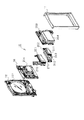
次に、第1制御基板ユニット201の構成を図14〜図17に基づいて説明する。図14は第1制御基板ユニット201の正面図、図15は同ユニット201の斜視図、図16は同ユニット201の分解斜視図、図17は同ユニット201を裏面から見た分解斜視図である。
Next, the configuration of the first
第1制御基板ユニット201は略L字状をなす取付台251を有し、取付台251に主制御装置271と音声ランプ制御装置272とが搭載されている。主制御装置271は、主たる制御を司るCPU、遊技プログラムを記憶したROM、遊技の進行に応じた必要なデータを記憶するRAM、各種機器との連絡をとるポート、各種抽選の際に用いられる乱数発生器、時間計数や同期を図る場合などに使用されるクロックパルス発生回路等を含む主基板を具備しており、主基板が透明樹脂材料等よりなる被包手段としての基板ボックス273に収容されて構成されている。なお、基板ボックス273は、略直方体形状のボックスベースと該ボックスベースの開口部を覆うボックスカバーとを備えている。これらボックスベースとボックスカバーとは封印手段としての封印ユニット274によって開封不能に連結され、これにより基板ボックス273が封印されている。
The first
封印ユニット274はボックスベースとボックスカバーとを開封不能に連結する構成であれば任意の構成が適用できるが、ここでは図15等に示すように、5つの封印部材が連結された構成となっており、この封印部材の長孔に係止爪を挿入することでボックスベースとボックスカバーとが開封不能に連結されるようになっている。封印ユニット274による封印処理は、その封印後の不正な開封を防止し、また万一不正開封が行われてもそのような事態を早期に且つ容易に発見可能とするものであって、一旦開封した後でも再度封印処理を行うこと自体は可能である。すなわち、封印ユニット274を構成する5つの封印部材のうち、少なくとも一つの封印部材の長孔に係止爪を挿入することにより封印処理が行われる。そして、収容した主基板の不具合発生の際や主基板の検査の際など基板ボックス273を開封する場合には、係止爪が挿入された封印部材と他の封印部材との連結を切断する。その後、再度封印処理する場合は他の封印部材の長孔に係止爪を挿入する。基板ボックス273の開封を行った旨の履歴を当該基板ボックス273に残しておけば、基板ボックス273を見ることで不正な開封が行われた旨が容易に発見できる。
As long as the
音声ランプ制御装置272は、表示制御装置214からの指示に従い音声やランプ表示の制御を司るCPUや、その他ROM、RAM、各種ポート等を含む音声ランプ制御基板を具備しており、音声ランプ制御基板が透明樹脂材料等よりなる基板ボックス275に収容されて構成されている。音声ランプ制御装置272上には電源中継基板276が搭載されており、電源装置313の電源が電源中継基板276を介して表示制御装置214及び音声ランプ制御装置272に供給されるようになっている。
The voice
取付台251は、ポリカーボネート樹脂等の合成樹脂製であり、例えば緑や青等に着色されて不透明とされている。但し、取付台251は無色透明又は半透明であってもよい。取付台251の表面には平坦状をなす2つの基板搭載面252,253が設けられている。これら基板搭載面252,253は縦横に直交する向きに延び、前後方向に段差をもって形成されている。基板搭載面252の上縁部及び下縁部にはそれぞれ、基板搭載面252より起立した起立部254が一体成形されている。そして、横長の基板搭載面252上に主制御装置271が配置されると共に、縦長の基板搭載面253上に音声ランプ制御装置272が配置される。このとき、主制御装置271は、上下の側部が起立部254にて支えられる。また、音声ランプ制御装置172は、複数箇所でネジ等により基板搭載面253に固定される。
The mounting
ここで、図16及び図17に示すように、基板搭載面252には、左右2カ所に横長形状の貫通孔256が形成されている。一方、主制御装置271の基板ボックス273には、その裏面の左右2カ所に回動操作式の固定具277が設けられている。主制御装置271を基板搭載面252に搭載する際には、基板搭載面252の貫通孔256に固定具277が挿通されるように主制御装置271を載置し、その状態で固定具277を回動操作することで主制御装置271がロックされる。従って、主制御装置271は第1制御基板ユニット201の裏面側から固定具277をロック解除しなければ取り外しできないため、基板取り外し等の不正行為に対して抑止効果が得られる。
Here, as shown in FIGS. 16 and 17, the
また、取付台251において、主基板用の基板搭載面252の下方には、基板搭載面252の裏面空間に通じる開口を遮蔽するための遮蔽部257が設けられている。従って、基板搭載面252の下方より取付台251の裏面に手などを差し入れることが阻止され、固定具277のロック状態を不正に解除することができないようになっている。また、第1制御基板ユニット201をパチンコ機10裏面に搭載した状態では、当該ユニット201の上部が裏パックユニット203により覆われるため、やはり取付台251の裏面に手などを差し入れることが阻止され、固定具277のロック状態を不正に解除することができないようになっている。
In addition, in the
前述した通り、第1制御基板ユニット201は、裏パックユニット203を所定角度以上に大きく開いた状態又は同ユニット203を取り外した状態でなければ取り外すことが不可能であり、また、施錠装置を正しくキー操作して外枠11に対して本体枠12を開放しなければ、裏パックユニット203を開くことができない構成となっている。つまり、本体枠12を開くことができなければ、結果的に第1制御基板ユニット201を回動させたり取り外すことができず、ひいては主制御装置271の取り外しも不可能となる。それ故、主制御装置271の不正な載せ替えや盗難等を効果的に防止することができる。
As described above, the first
主制御装置271は、パチンコ機10裏面から見て手前側に配置され、音声ランプ制御装置272はその奥側に配置される。この場合、基板搭載面252,253が前後方向に段差をもって形成されているため、これら基板搭載面252,253に主制御装置271及び音声ランプ制御装置272を搭載した状態において各制御装置271,272はその一部を前後に重ねて配置される。つまり、図15等にも見られるように、主制御装置271はその一部(本実施の形態では1/3程度)が浮いた状態で配置される。故に、主制御装置271に重なる領域まで音声ランプ制御装置272を拡張することが可能となり、また別の見方をすれば音声ランプ制御装置272に重なる領域まで主制御装置271を拡張することが可能となり、パチンコ機10という限られた大きさの中にあっても、各制御装置271,272の大型化に良好に対処できるとともに、各制御装置271,272を効率良く設置できる。また、第1制御基板ユニット201を遊技盤30に装着した状態では、基板搭載面252の後方にスペースが確保され、各可変入賞装置32a,32bやその電気配線等が無理なく設置できるようになっている。なお、基板搭載面252の裏面には格子状のリブ258が設けられており、主制御装置271の支持強度が高められている。
The
取付台251の左端面には上下一対の掛止ピン261が設けられており、この掛止ピン261を前記軸受け金具231に取り付けることで、第1制御基板ユニット201が遊技盤30に対して回動可能に片持ち支持される。取付台251の右端部には前記被締結孔232にはめ込まれる締結具として上下一対のナイラッチ262が設けられている。取付台251の上端部には前記係止爪片233が係止される長孔263が設けられている。従って、ナイラッチ262を被締結孔232にはめ込むと共に、長孔263に係止爪片233を係止させることで、第1制御基板ユニット201が遊技盤30に固定される。なお、軸受け金具231及び掛止ピン261が前記支軸部M1に、被締結孔232及びナイラッチ262が前記締結部M2に、係止爪片233及び長孔263が前記係止爪部M3に、それぞれ相当する。
A pair of upper and lower retaining pins 261 are provided on the left end surface of the mounting
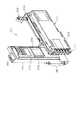
次に、第2制御基板ユニット202の構成を図18〜図20に基づいて説明する。図18は第2制御基板ユニット202の正面図、図19は同ユニット202の斜視図、図20は同ユニット202の分解斜視図である。
Next, the configuration of the second
第2制御基板ユニット202は横長形状をなす取付台301を有し、取付台301に払出制御装置311、発射制御装置312、電源装置313及びカードユニット接続基板314が搭載されている。払出制御装置311及び発射制御装置312は制御の中枢をなすCPUや、その他ROM、RAM、各種ポート等を含む制御基板を具備している。払出制御装置311の払出制御基板により、賞球や貸出球の払出が制御される。発射制御装置312の発射制御基板により、遊技者による遊技球発射ハンドル18の操作に従い発射モータ229の制御が行われる。また、電源装置313の電源基板により、各種制御装置等で要する所定の電源電圧が生成され出力される。カードユニット接続基板314は、パチンコ機前面の貸球操作部120及び図示しないカードユニットに電気的に接続され、主として遊技者による球貸し操作の指令を取り込んでそれを払出制御装置311に出力するものである。なお、カードユニットを介さずに球貸し装置等から上皿に遊技球が直接貸し出される現金機では、カードユニット接続基板314は不要である。
The second
上記払出制御装置311、発射制御装置312、電源装置313及びカードユニット接続基板314は、透明樹脂材料等よりなる基板ボックス315,316,317,318にそれぞれ収容されて構成されている。特に、払出制御装置311では、主制御装置271と同様、被包手段を構成する基板ボックス315がボックスベースとボックスカバーとを備え、それらが封印手段としての封印ユニット319によって開封不能に連結され、これにより基板ボックス315が封印されている。払出制御装置311には状態復帰スイッチ321が設けられている。例えば、後述する払出モータの球詰まり等、払出エラーの発生時において状態復帰スイッチ321が押されると、払出モータが正逆回転され、球詰まりの解消(正常状態への復帰)が図られるようになっている。電源装置313にはRAM消去スイッチ323が設けられている。本パチンコ機10は各種データのバックアップ機能を有しており、万一停電が発生した際でも停電時の状態を保持し、停電からの復帰(復電)の際には停電時の状態に復帰できるようになっている。従って、例えば遊技ホールの営業終了の場合のように通常手順で電源を遮断すると遮断前の状態が記憶保持されるが、RAM消去スイッチ323を押しながら電源を投入すると、RAMデータが初期化されるようになっている。
The
取付台301は例えば無色透明な樹脂成型品よりなり、その表面に平坦状をなす基板搭載面302が設けられている。基板搭載面302には、発射制御装置312、電源装置313及びカードユニット接続基板314が横並びとなった状態で搭載され、ネジ等で固定されている。電源装置313の基板ボックス317上には略平板状の台座プレート303が載置されるとともに台座プレート303上に払出制御装置311が搭載され、ネジ等で固定されている。払出制御装置311と電源装置313との間には台座プレート303が介在するため、例えばノイズ除去用の金属プレート等を設置するには台座プレート303に金属プレート等を取り付ければ良く、ノイズ対策が簡単に実現できる。
The mounting
取付台301には、パチンコ機10後方からみて右端部に上下一対の掛止ピン305が設けられており、掛止ピン305を前記軸受け部237に上方から挿通させることで、第2制御基板ユニット202が本体枠12に対して回動可能に片持ち支持される。取付台301の左端部には締結具として上下一対のナイラッチ306が設けられており、ナイラッチ306を前記被締結孔239にはめ込むことで、第2制御基板ユニット202が本体枠12に固定される。なお、軸受け部237及び掛止ピン305が前記支軸部M4に、被締結孔239及びナイラッチ306が前記締結部M5に、それぞれ相当する。
The mounting
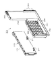
次に、裏パックユニット203の構成を図21及び図22に基づいて説明する。図21は裏パックユニット203の正面図、図22は裏パックユニット203の分解斜視図である。
Next, the configuration of the
裏パックユニット203は、裏パック351と遊技球の払出機構部352とが一体化されることにより構成されている。裏パック351は例えばABS樹脂等の合成樹脂により一体成型されており、略平坦状のベース部353と、パチンコ機10後方に突出し横長の略直方体形状をなす保護カバー部354とを有する。保護カバー部354は左右側面及び上面が閉鎖され且つ下面のみが開放された形状をなし、少なくとも可変表示ユニット35を囲むのに十分な大きさを有する。但し、本実施の形態では、前述の音声ランプ制御装置272も併せて囲む構成となっている。保護カバー部354の背面には多数の通気孔354aが設けられている。通気孔354aは各々が長孔状をなし、それぞれの通気孔354aが比較的近い位置で隣り合うよう設けられている。従って、隣り合う通気孔354a間にある樹脂部分を切断することにより、裏パック351の背面を容易に開口させることができる。つまり、通気孔354a間の樹脂部分を切断してその内部の表示制御装置214等を露出させることで、所定の検定等を容易に行うことができるようになっている。
The
裏パック351のベース部353には、保護カバー部354を迂回するようにして払出機構部352が配設されている。すなわち、裏パック351の最上部には上方に開口したタンク355が設けられており、タンク355には遊技ホールの島設備から供給される遊技球が逐次補給される。タンク355の下方には、例えば横方向2列(2条)の球通路を有し下流側に向けて緩やかに傾斜するタンクレール356が連結され、タンクレール356の下流側には上下方向に延びるケースレール357が連結されている。払出装置358はケースレール357の最下流部に設けられ、払出制御装置311の制御により払出モータ358aが駆動されて必要個数の遊技球の払出が適宜行われる。払出装置358より払い出された遊技球は払出通路359等を通じて前記上皿23等に供給される。なお、図示は省略するが、ケースレール357の上流部には、タンク355やタンクレール356から供給される遊技球の有無を検出するタンク球無しセンサが設けられている。また、払出装置358には、払出モータ358aの回転を検出する払出回転センサと、払い出される遊技球数をカウントする払出カウントスイッチとが設けられている。
On the
タンクレール356には、当該タンクレール356に振動を付加するためのバイブレータ360が取り付けられている。バイブレータ360は、バイブモータとそのバイブモータを収容する合成樹脂製のケースとによりユニット化されており、2本の脚部360aでタンクレール356に取り付けられている。従って、仮にタンクレール356付近で球詰まりが生じた際、バイブレータ360が駆動されることで球詰まりが解消されるようになっている。
A
払出機構部352には、払出制御装置311から払出装置358への払出指令の信号を中継する払出中継基板381が設置されると共に、外部より主電源を取り込むための電源スイッチ基板382が設置されている。電源スイッチ基板382には、電圧変換器を介して例えば交流24ボルトの主電源が供給され、電源スイッチ382aの切り替え操作により電源ON又は電源OFFとされるようになっている。
The
タンク355から払出通路359に至るまでの払出機構部352は何れも導電性を有する合成樹脂材料、例えば導電性ポリカーボネート樹脂にて成形され、その一部にてアースされている。これにより、遊技球の帯電によるノイズの発生が抑制されるようになっている。
The
裏パック351には、その右上部に枠用外部端子板390が設けられている。枠用外部端子板390には、タンク355やタンクレール356で遊技球が不足した場合に信号出力するための出力端子、所定個数の賞球を払い出す毎に信号出力するための出力端子、所定個数の遊技球を貸し出す毎に信号出力するための出力端子、本体枠12の開放時に信号出力するための出力端子、及び前扉枠13の開放時に信号出力するための出力端子が設けられている。そして、これらの出力端子を通じて、遊技ホール側の管理制御装置に対して枠側の状態に関する信号が出力される。なお、所定個数の遊技球を貸し出す毎に信号出力するための出力端子はいわゆる現金機においては不要である。
The
裏パック351には、枠用外部端子板390に隣接して略四角形状の窓部391が設けられている。従って、裏パックユニット203を本体枠12に取り付けた状態では、窓部391を通じて遊技盤30裏面の盤用外部端子板230が露出し、裏パックユニット203を装着したままで盤用外部端子板230の操作を行うことができるようになっている。前述のとおり、盤用外部端子板230は取り外し容易な状態で集合板ユニット215に取り付けられていることから、盤用外部端子板230の配線を接続したままで、窓部391を介して当該盤用外部端子板230を取り出すことも可能となる。裏パック351の右上部には本体枠12の開放の状態を検出するための本体枠開放スイッチ392が設けられており、外枠11に対して本体枠12を閉じた状態では当該スイッチ392の金属接点が閉じて本体枠12の閉鎖が検知され、外枠11に対して本体枠12を開いた状態では金属接点が開いて本体枠12の開放が検知されるようになっている。
The
裏パック351には、パチンコ機10後方からみて右端部に上下一対の掛止ピン385が設けられており、掛止ピン385を前記軸受け部238に上方から挿通させることで、裏パックユニット203が本体枠12に対して回動可能に片持ち支持される。裏パック351には、左端部に締結具として上下一対のナイラッチ386が設けられると共に、上端部に係止孔387が設けられており、ナイラッチ386を前記被締結孔240にはめ込むと共に、係止孔387に前記固定具242を挿入した上で当該固定具242を回動操作することで、裏パックユニット203が本体枠12に固定される。また、前記固定具241,243によっても裏パックユニット203が本体枠12に固定される。なお、軸受け部238及び掛止ピン385が前記支軸部M6に、被締結孔240及びナイラッチ386が前記締結部M7に、固定具242及び係止孔387が前記係止部M8に、それぞれ相当する。また、固定具243が前記係止部M9に相当する。
The
次に、本パチンコ機10の電気的構成について、図23のブロック図に基づいて説明する。
Next, the electrical configuration of the
主制御装置271には、演算装置である1チップマイコンとしてのCPU501が搭載されている。CPU501には、該CPU501により実行される各種の制御プログラムや固定値データを記憶したROM502と、そのROM502内に記憶される制御プログラムの実行に際して各種のデータ等を一時的に記憶するためのメモリであるRAM503と、割込回路やタイマ回路、データ送受信回路などの各種回路が内蔵されている。
The
RAM503は、パチンコ機10の電源の遮断後においても電源装置313からバックアップ電圧が供給されてデータを保持(バックアップ)できる構成となっており、RAM503には、各種のデータ等を一時的に記憶するためのメモリやエリアの他に、バックアップエリア503aが設けられている。
The
バックアップエリア503aは、停電などの発生により電源が遮断された場合において、電源遮断時(停電発生時を含む。以下同様)のスタックポインタや、各レジスタ、I/O等の値を記憶しておくためのエリアであり、電源投入時(停電解消による電源投入を含む。以下同様)には、バックアップエリア503aの情報に基づいてパチンコ機10の状態が電源遮断前の状態に復帰できるようになっている。バックアップエリア503aへの書き込みはNMI割込み処理(図31参照)によって電源遮断時に実行され、バックアップエリア503aに書き込まれた各値の復帰は電源投入時のメイン処理(図32参照)において実行される。なお、CPU501のNMI端子(ノンマスカブル割込端子)には、停電等の発生による電源遮断時に、停電監視回路542からの停電信号SG1が入力されるように構成されており、停電の発生により停電時処理としてのNMI割込み処理が即座に実行される。
The backup area 503a stores values such as a stack pointer, each register, and I / O when the power is shut down (including when a power failure occurs, the same applies hereinafter) when the power is shut down due to the occurrence of a power failure or the like. The area of the
主制御装置271のCPU501には、アドレスバス及びデータバスで構成されるバスライン504を介して入出力ポート505が接続されている。主制御装置271の入力側には、後述するRAM消去スイッチ回路543、払出制御装置311や、その他図示しないスイッチ群などが接続されている。一方、主制御装置271の出力側には、払出制御装置311や表示制御装置214が接続されている。また、各特定ランプ部47,48に配設されたLEDのスイッチや役物ランプ部49に配設されたLEDのスイッチも接続されている。つまり、各特定ランプ部47,48と役物ランプ部49は、主制御装置271により直接制御されている。なお、図示は省略したが、主制御装置271の出力側には、可変表示ユニット35の保留ランプ44,役物ランプ部49に配設されたランプスイッチも接続されている。
An input /
払出制御装置311は、払出モータ358aにより賞球や貸出球の払出制御を行うものである。演算装置であるCPU511は、そのCPU511により実行される制御プログラムや固定値データ等を記憶したROM512と、ワークメモリ等として使用されるRAM513とを備えている。
The
払出制御装置311のRAM513は、主制御装置271のRAM503と同様に、パチンコ機10の電源の遮断後においても電源装置313からバックアップ電圧が供給されてデータを保持(バックアップ)できる構成となっており、RAM513には、各種のデータ等を一時的に記憶するためのメモリやエリアの他に、バックアップエリア513aが設けられている。
The
バックアップエリア513aは、停電などの発生により電源が遮断された場合において、電源遮断時のスタックポインタや、各レジスタ、I/O等の値を記憶しておくためのエリアであり、電源投入時には、このバックアップエリア513aの情報に基づいてパチンコ機10の状態が電源遮断前の状態に復帰できるようになっている。バックアップエリア513aへの書き込みはNMI割込み処理によって電源遮断時に実行され、バックアップエリア513aに書き込まれた各値の復帰は電源投入時のメイン処理において実行される。なお、主制御装置271のCPU501と同様、CPU511のNMI端子にも、停電等の発生による電源遮断時に停電監視回路542から停電信号SG1が入力されるように構成されており、停電の発生により、NMI割込み処理が即座に実行されるようになっている。
The backup area 513a is an area for storing the stack pointer, registers, I / O, and other values when the power is cut off when the power is cut off due to a power failure or the like. Based on the information in the backup area 513a, the state of the
払出制御装置311のCPU511には、アドレスバス及びデータバスで構成されるバスライン514を介して入出力ポート515が接続されている。入出力ポート515には、RAM消去スイッチ回路543、主制御装置271、発射制御装置312、払出モータ358aなどがそれぞれ接続されている。
An input /
発射制御装置312は、発射モータ229による遊技球の発射を許可又は禁止するものであり、発射モータ229は、所定条件が整っている場合に駆動が許可される。具体的には、払出制御装置311から発射許可信号が出力されていること、遊技者が遊技球発射ハンドル18に触れていることをセンサ信号により検出していること、発射を停止させるための発射停止スイッチが操作されていないことを条件に、発射モータ229が駆動され、遊技球発射ハンドル18の操作量に応じた強さで遊技球が発射される。
The
表示制御装置214は、図柄表示装置41における図柄の変動表示や大当たり状態下の大当たり表示を制御するものである。表示制御装置214は、CPU521と、プログラムROM522と、ワークRAM523と、ビデオRAM524と、キャラクタROM525と、画像コントローラ526と、入力ポート527と、2つの出力ポート528,529と、バスライン530,531とを備えている。入力ポート527の入力側には主制御装置271の出力側が接続されている。入力ポート527の出力側には、CPU521、プログラムROM522、ワークRAM523、画像コントローラ526が接続されると共にバスライン530を介して出力ポート528が接続されている。出力ポート528の出力側には音声ランプ制御装置272が接続されている。また、画像コントローラ526にはバスライン531を介して出力ポート529が接続されており、その出力ポート529の出力側には図柄表示装置41が接続されている。
The
表示制御装置214のCPU521は、主制御装置271から送信される変動パターンコマンド等の各種コマンドに基づいて図柄表示装置41の表示制御を行うと共に、音声ランプ制御装置272に対して制御コマンドを送信する。プログラムROM522は、CPU521により実行される各種の制御プログラムや背景画像データ等の固定値データを記憶するためのメモリであり、ワークRAM523は、CPU521による各種プログラムの実行時に使用されるワークデータやフラグを一時的に記憶するためのメモリである。
The
ビデオRAM524は、図柄表示装置41に表示される表示データを記憶するためのメモリであり、ビデオRAM524の内容を書き替えることにより、図柄表示装置41の表示内容が変更される。キャラクタROM525は、図柄表示装置41に表示される図柄などのキャラクタデータを記憶するためのメモリである。画像コントローラ526は、CPU521、ビデオRAM524、出力ポート529のそれぞれのタイミングを調整してデータの読み書きに介在すると共に、ビデオRAM524に記憶される表示データを、キャラクタROM525から所定のタイミングで読み出して図柄表示装置41に表示させるものである。
The
音声ランプ制御装置272は、表示制御装置214から送信される制御コマンドに基づいてスピーカ20や環状電飾部102等を制御するものであり、CPUやROM、RAM、各種ポート等を備えている。
The sound
電源装置313は、パチンコ機10の各部に電源を供給するための電源部541と、停電等による電源遮断を監視する停電監視回路542と、RAM消去スイッチ323に接続されてなるRAM消去スイッチ回路543とを備えている。電源部541は、図示しない電源経路を通じて、主制御装置271や払出制御装置311等に対して各々に必要な動作電源を供給する。その概要としては、電源部541は、外部より供給される交流24ボルト電源を取り込み、各種スイッチやモータ等を駆動するための+12V電源、ロジック用の+5V電源、RAMバックアップ用のバックアップ電源などを生成し、これら+12V電源、+5V電源及びバックアップ電源を主制御装置271や払出制御装置311等に対して供給する。なお、発射制御装置312に対しては払出制御装置311を介して動作電源(+12V電源、+5V電源等)が供給される。
The
停電監視回路542は、停電等の発生による電源遮断時に、主制御装置271のCPU501及び払出制御装置311のCPU511の各NMI端子へ停電信号SG1を出力するための回路である。停電監視回路542は、電源部541から出力される最大電圧である直流安定24ボルトの電圧を監視し、この電圧が22ボルト未満になった場合に停電(電源遮断)の発生と判断して、停電信号SG1を主制御装置271及び払出制御装置311へ出力する。停電信号SG1の出力によって、主制御装置271及び払出制御装置311は、停電の発生を認識し、NMI割込み処理を実行する。なお、電源部541は、直流安定24ボルトの電圧が22ボルト未満になった後においても、NMI割込み処理の実行に充分な時間の間、制御系の駆動電圧である5ボルトの出力を正常値に維持するように構成されている。よって、主制御装置271及び払出制御装置311は、NMI割込み処理を正常に実行し完了することができる。
The power
RAM消去スイッチ回路543は、RAM消去スイッチ323のスイッチ信号を取り込み、そのスイッチ323の状態に応じて主制御装置271及び払出制御装置311のバックアップデータをクリアするためのRAM消去信号SG2を出力する回路である。RAM消去スイッチ323が押された際、RAM消去スイッチ回路543は、主制御装置271及び払出制御装置311に対してRAM消去信号SG2を出力する。これにより、RAM消去スイッチ323が押された状態でパチンコ機10の電源が投入されると、主制御装置271及び払出制御装置311においてそれぞれのバックアップエリア503a,513aのデータがクリアされる。
The RAM erase
ここで、図柄表示装置41の表示内容について図24、図25に基づいて説明する。図24は図柄表示装置41にて変動表示される図柄を個々に示す図であり、図25は図柄表示装置41の表示画面Gを示す図である。
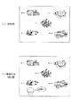
Here, the display contents of the
図24(a)〜(j)に示すように、図柄は、「1」〜「9」の数字が各々付された9種類の主図柄と、貝形状の絵図柄からなる副図柄とにより構成されている。より詳しくは、タコ等の9種類のキャラクタ図柄の右側に「1」〜「9」の数字がそれぞれ付されて主図柄が構成されている。 As shown in FIGS. 24 (a) to 24 (j), the symbol is composed of nine types of main symbols with numbers "1" to "9", respectively, and sub-patterns composed of shell-shaped symbols. Has been. More specifically, the numbers “1” to “9” are attached to the right side of nine types of character symbols such as octopus to form the main symbol.
次に、図柄表示装置41の表示画面Gについて説明する。図25(a)に示すように、図柄表示装置41の表示画面Gには、上段・中段・下段の3つの図柄列Z1,Z2,Z3が設定されている。各図柄列Z1〜Z3は、上述した主図柄と副図柄が所定の順序で配列されて構成されている。詳細には、上図柄列Z1には、「1」〜「9」の9種類の主図柄が数字の降順に配列されると共に、各主図柄の間に副図柄が1つずつ配されている。下図柄列Z3には、「1」〜「9」の9種類の主図柄が数字の昇順に配列されると共に、各主図柄の間に副図柄が1つずつ配されている。つまり、上図柄列Z1と下図柄列Z3は18個の図柄により構成されている。これに対し、中図柄列Z2には、数字の昇順に「1」〜「9」の9種類の主図柄が配列された上で「9」の主図柄と「1」の主図柄との間に「4」の主図柄が付加的に配列され、これら各主図柄の間に副図柄が1つずつ配されている。つまり、中図柄列Z2に限っては、10個の主図柄が配されて20個の図柄により構成されている。そして、表示画面Gでは、これら各図柄列Z1〜Z3の図柄が周期性をもって所定の向きにスクロールするように変動表示される。より詳しくは、各作動口33aに遊技球が入賞した場合、これら各図柄列Z1〜Z3の図柄が右から左へとスクロールするように変動表示される。また、図25(b)に示すように、表示画面Gは、図柄列毎に3個の図柄が停止表示されるようになっており、結果として3×3の計9個の図柄が停止表示されるようになっている。
Next, the display screen G of the
また、表示画面Gには、5つの有効ライン、すなわち左ラインL1、中ラインL2、右ラインL3、右下がりラインL4、右上がりラインL5が設定されている。そして、上図柄列Z1→下図柄列Z3→中図柄列Z2の順に変動表示が停止し、いずれかの有効ラインに大当たり図柄の組み合わせ(本実施の形態では同一主図柄の組み合わせ)が形成された状態で全図柄列Z1〜Z3の変動表示が終了すれば、大当たり発生として大当たり動画が表示されるようになっている。また、大当たりの前段階として、上図柄列Z1と下図柄列Z3の同一主図柄がいずれかの有効ラインに停止表示されるとリーチとなり、その後にリーチ演出が行われる。なお以下の説明では便宜上、各主図柄を各々に付された数字で記述することとし、具体的にはそれぞれ「1」図柄、「2」図柄、「3」図柄、・・・「9」図柄と記述する。また、リーチとなった場合の上図柄列Z1と下図柄列Z3の同一主図柄をリーチ図柄と記述し、リーチ図柄が停止した有効ラインをリーチラインと記述する。 The display screen G has five effective lines, that is, a left line L1, a middle line L2, a right line L3, a right lowering line L4, and a right uppering line L5. Then, the variable display is stopped in the order of the upper symbol row Z1 → the lower symbol row Z3 → the middle symbol row Z2, and a combination of jackpot symbols (a combination of the same main symbols in the present embodiment) is formed on any effective line. If the fluctuation display of all the symbol rows Z1 to Z3 is finished in the state, a big hit video is displayed as a big hit occurrence. In addition, as the previous stage of jackpot, when the same main symbol of the upper symbol row Z1 and the lower symbol row Z3 is stopped and displayed on any one of the effective lines, reach is performed, and then reach effect is performed. In the following description, for the sake of convenience, each main symbol is described by a number attached to each. Specifically, “1” symbol, “2” symbol, “3” symbol,... “9” symbol, respectively. Is described. In addition, the same main symbol in the upper symbol row Z1 and the lower symbol row Z3 when reaching reach is described as a reach symbol, and an effective line where the reach symbol is stopped is described as a reach line.
さらに、表示画面Gの左下角隅部には、小領域で区画された第1副表示領域Gaが設定されており、表示画面Gの右下角隅部には、小領域で区画された第2副表示領域Gbが設定されている。両副表示領域Ga,Gbには、図柄とは別に周期的に変動表示される貝キャラクタがそれぞれ表示されている。貝キャラクタは、その貝殻部が周期的に開閉を繰り返すように変動表示される。そして、特定大当たりの場合には貝殻部が完全に開放された状態で変動表示が終了され、非特定大当たりの場合には貝殻部が半分開放された状態で変動表示が終了され、外れの場合には貝殻部が閉鎖された状態で変動表示が終了されるようになっている。また、詳細は後述するが、第1特定ランプ部47の切り替え表示が行われる場合に第1副表示領域Gaの貝キャラクタが変動表示され、第2特定ランプ部48の切り替え表示が行われる場合に第2副表示領域Gbの貝キャラクタが変動表示されるようになっている。
Furthermore, a first sub display area Ga partitioned by a small area is set in the lower left corner of the display screen G, and a second partitioned by a small area is set in the lower right corner of the display screen G. A sub display area Gb is set. In the sub display areas Ga and Gb, shell characters that are displayed in a cyclic manner separately from the symbols are displayed. The shell character is variably displayed so that the shell portion repeats opening and closing periodically. In the case of a specific jackpot, the fluctuation display is terminated with the shell part fully open, and in the case of a non-specific jackpot, the fluctuation display is terminated with the shell part half open, The change display is terminated when the shell is closed. As will be described in detail later, when the switching display of the first
次に、上記の如く構成されたパチンコ機10の動作について説明する。
Next, the operation of the
本実施の形態では、主制御装置271内のCPU501は、遊技に際し各種カウンタ情報を用いて、大当たり抽選、各特定ランプ部47,48の発光色の設定や、図柄表示装置41の図柄表示の設定などを行うこととしており、具体的には、図26に示すように、大当たりの抽選に使用する大当たり乱数カウンタC1と、大当たり状態が終了した場合に、通常状態に移行するか高確率状態に移行するかの抽選に使用する移行乱数カウンタC2と、図柄を外れ変動させる際のリーチ抽選に使用するリーチ乱数カウンタC3と、大当たり乱数カウンタC1の初期値設定に使用する乱数初期値カウンタCINIと、図柄の変動パターン選択に使用する変動種別カウンタCSと、上図柄列Z1、中図柄列Z2及び下図柄列Z3の各外れ図柄の設定に使用する上・中・下の各外れ図柄カウンタCU,CM,CLとを用いることとしている。
In the present embodiment, the
このうち、カウンタC1〜C3,CINI,CSは、その更新の都度前回値に1が加算され、最大値に達した後0に戻るループカウンタとなっている。また、外れ図柄カウンタCU,CM,CLは、CPU501内のRレジスタ(リフレッシュレジスタ)を用いてレジスタ値が加算され、結果的に数値がランダムに変化する構成となっている。各カウンタは短時間間隔で更新され、その更新値がRAM503の所定領域に設定されたカウンタ用バッファに適宜格納される。RAM503には、第1特定ランプ部用保留エリアRaと、第2特定ランプ部用保留エリアRbと、共通保留エリアCRと、実行エリアとよりなる保留球格納エリアが設けられている。そして、この保留球格納エリアに、各作動口33a,33bへの遊技球の入賞履歴に合わせて、大当たり乱数カウンタC1、移行乱数カウンタC2及びリーチ乱数カウンタC3との各値が時系列的に格納されるようになっている。
Among these counters, the counters C1 to C3, CINI, and CS are loop counters that add 1 to the previous value every time they are updated, and return to 0 after reaching the maximum value. Further, the out symbol counters CU, CM, CL are configured such that register values are added using an R register (refresh register) in the
大当たり乱数カウンタC1は、例えば0〜1439の範囲内で順に1ずつ加算され、最大値(つまり1439)に達した後0に戻る構成となっている。特に大当たり乱数カウンタC1が1周した場合、その時点の乱数初期値カウンタCINIの値が当該大当たり乱数カウンタC1の初期値として読み込まれる。なお、乱数初期値カウンタCINIは、大当たり乱数カウンタC1と同様のループカウンタであり(値=0〜1439)、タイマ割込み毎に1回更新されると共に通常処理の残余時間内で繰り返し更新される。大当たり乱数カウンタC1は定期的に(本実施の形態ではタイマ割込み毎に1回)更新され、遊技球が各作動口33a、33bに入賞したタイミングでRAM503の保留球格納エリアに格納される。より詳しくは、第1作動口33aに遊技球が入賞したタイミングでRAM503の第1特定ランプ部用保留エリアRaに格納され、第2作動口33bに遊技球が入賞したタイミングでRAM503の第2特定ランプ部用保留エリアRbに格納される。すなわち、いずれの作動口33a,33bに遊技球が入賞した場合であっても、この大当たり乱数カウンタC1の値が格納される。大当たりとなる乱数の値の数は、通常状態と高確率状態とで2種類設定されており、通常状態下で大当たりとなる乱数の値の数は9で、その値は「29,31,37,47,97,101,123,337,673」であり、高確率状態下で大当たりとなる乱数の値の数は28で、その値は「17,19,23,43,59,61,67,73,79,83,89,93,103,113,134,201,268,337,402,469,536,603,673,737,804,871,938,1005」である。つまり、通常状態では大当たり確率は約170分の1、高確率状態では約51分の1である。さらに、詳細は後述するが、第1作動口33aに遊技球が入賞したことに基づいて大当たりに当選した場合には、大当たりにおけるラウンド数が1〜9ラウンドのいずれかに設定される。取得された乱数によってラウンド数は決定されており、例えば、通常状態において大当たり乱数カウンタC1の値が「29」にて大当たりに当選した場合にはラウンド数は2となり、通常状態において大当たり乱数カウンタC1の値が「31」にて大当たりに当選した場合にはラウンド数は2となり。通常状態において大当たり乱数カウンタC1の値が「673」にて大当たりとなった場合にラウンド数が9となる。すなわち、通常状態にて大当たりとなる乱数の小さい方から順にラウンド数が1、2、3、・・・、8、9と設定されている。遊技状態が大当たり状態の場合についてはは後述する。
The jackpot random number counter C1 is configured so that, for example, 1 is sequentially added within a range of 0 to 1439, and after reaching the maximum value (that is, 1439), it returns to 0. In particular, when the jackpot random number counter C1 makes one round, the value of the random number initial value counter CINI at that time is read as the initial value of the jackpot random number counter C1. The random number initial value counter CINI is a loop counter similar to the jackpot random number counter C1 (value = 0 to 1439), and is updated once for each timer interruption and is repeatedly updated within the remaining time of normal processing. The jackpot random number counter C1 is updated periodically (once every timer interruption in the present embodiment), and stored in the reserved ball storage area of the
なお、本実施の形態では、高確率状態において第1作動口33aに遊技球が入賞したことに基づいて大当たりと判定された場合には全てラウンド数が2となるように設定されている。また、高確率状態とは、大当たり状態の終了後に付加価値としてその後の大当たり確率がアップした状態、いわゆる確変状態のことをいい、通常状態(低確率状態)とはそのような高確率状態でない遊技状態をいう。さらに、本実施形態では、遊技状態として時短状態が設定されている。時短状態における大当たりとなる乱数は通常状態と同様になっている。時短状態については後述する。
In the present embodiment, the number of rounds is all set to 2 when it is determined that the game is won based on the winning of the game ball in the
移行乱数カウンタC2は、0〜25の範囲内で順に1ずつ加算され、最大値(つまり25)に達した後0に戻る構成となっている。そして、本実施の形態では、移行乱数カウンタC2によって、大当たり状態の終了後に高確率状態に移行させるか否かを決定することとしており、例えば、第1大当たり状態においては、C2=0〜13の場合に大当たり状態終了後に高確率状態に移行し、C2=14〜25の場合に大当たり状態終了後に通常状態に移行する。すなわち、第1大当たり状態が終了した場合の2分の1で高確率状態に移行する。また、移行乱数カウンタC2及び大当たり状態に関しての詳細については後述する。 The transition random number counter C2 is configured so that 1 is added in order within a range of 0 to 25 and returns to 0 after reaching the maximum value (that is, 25). In this embodiment, the transition random number counter C2 determines whether or not to shift to the high probability state after the end of the jackpot state. For example, in the first jackpot state, C2 = 0 to 13 When the jackpot state ends, the state shifts to a high probability state, and when C2 = 14 to 25, the state shifts to the normal state after the end of the jackpot state. That is, it shifts to a high probability state in half of the case where the first jackpot state is finished. Details of the transition random number counter C2 and the jackpot state will be described later.
リーチ乱数カウンタC3は、例えば0〜110の範囲内で順に1ずつ加算され、最大値(つまり110)に達した後0に戻る構成となっている。本実施の形態では、リーチ乱数カウンタC3によって、最終停止図柄列(本実施の形態では中図柄列Z2)のその遊技回で大当たりとなり得る大当たり図柄(具体的にはリーチ図柄と同一の主図柄)がリーチラインから前後に1つだけずれて停止する「前後外れリーチ」と、最終停止図柄列の大当たり図柄がリーチラインの前後以外で停止する「前後外れ以外リーチ」と、上図柄列Z1と下図柄列Z3の同一主図柄が有効ラインに停止せずリーチとならない「完全外れ」とを抽選することとしている。つまり、本実施の形態では、リーチ乱数カウンタC3によって外れリーチを行うか否かを抽選することとしており、例えばC3=0,1が前後外れリーチに該当し、C3=2〜21が前後外れ以外リーチに該当し、C3=22〜110が完全外れに該当する。なお、リーチの抽選は、遊技状態や変動開始時の作動保留球数等に応じて各々個別に設定されるものであっても良い。リーチ乱数カウンタC3は定期的に(本実施の形態ではタイマ割込み毎に1回)更新され、遊技球が各作動口33a,33bに入賞したタイミングでRAM503の保留球格納エリアに格納される。より詳しくは、第1作動口33aに遊技球が入賞したタイミングでRAM503の第1特定ランプ部用保留エリアRaに格納され、第2作動口33bに遊技球が入賞したタイミングでRAM503の第2特定ランプ部用保留エリアRbに格納される。すなわち、いずれの作動口33a,33bに遊技球が入賞した場合であっても、このリーチ乱数カウンタC3の値が格納される。
For example, the reach random number counter C3 is incremented one by one within a range of 0 to 110, for example, and reaches a maximum value (that is, 110) and then returns to 0. In the present embodiment, the reach random number counter C3 causes a jackpot symbol (specifically, the same main symbol as the reach symbol) that can be a big hit in the game times of the last stop symbol sequence (in the present embodiment, the middle symbol sequence Z2). The front-rear-reach reach that stops by one shift forward and backward from the reach line, the “reach other than front-rear-reach” where the jackpot symbol of the final stop symbol line stops other than before and after the reach line, and the upper symbol line Z1 and lower It is assumed that the same main symbol of the symbol row Z3 does not stop at the active line and does not reach and “lots out” are selected. In other words, in the present embodiment, whether or not to perform detach reach is determined by lottery by the reach random number counter C3. This corresponds to reach, and C3 = 22 to 110 corresponds to complete detachment. Note that the reach lottery may be set individually according to the game state, the number of activated balls at the start of change, and the like. The reach random number counter C3 is updated periodically (once every timer interruption in the present embodiment), and stored in the reserved ball storage area of the
変動種別カウンタCSは、例えば0〜198の範囲内で順に1ずつ加算され、最大値(つまり198)に達した後0に戻る構成となっている。変動種別カウンタCSによって、いわゆるノーマルリーチ、スーパーリーチ等のリーチ種別やその他大まかな図柄変動態様が決定される。変動種別カウンタCSは、後述する通常処理が1回実行される毎に1回更新され、当該通常処理内の残余時間内でも繰り返し更新される。そして、図柄の変動開始時における変動パターン決定に際して変動種別カウンタCSのバッファ値が取得される。 For example, the variation type counter CS is incremented one by one within a range of 0 to 198, for example, and reaches a maximum value (that is, 198) and then returns to 0. The variation type counter CS determines a reach type such as normal reach and super reach, and other rough symbol variation modes. The variation type counter CS is updated once every time a normal process to be described later is executed once, and is repeatedly updated even within the remaining time in the normal process. Then, the buffer value of the variation type counter CS is acquired when determining the variation pattern at the start of symbol variation.
上・中・下の各外れ図柄カウンタCU,CM,CLは、大当たり抽選が外れとなった時に上図柄列Z1、中図柄列Z2、下図柄列Z3の左ラインL1に停止表示させる停止図柄を決定するためのものであり、各図柄列Z1〜Z3において変動表示される図柄の数と同数のカウンタ値が用意されている。すなわち、上・外れ図柄カウンタCUと下・外れ図柄カウンタCLには18個(0〜17)のカウンタ値が用意されており、中・外れ図柄カウンタCMには20個(0〜19)のカウンタ値が用意されている。上・外れ図柄カウンタCUにより上図柄列Z1の左ラインL1に停止表示させる停止図柄が決定され、中・外れ図柄カウンタCMにより中図柄列Z2の左ラインL1に停止表示させる停止図柄が決定され、下・外れ図柄カウンタCLにより下図柄列Z3の左ラインL1に停止表示させる停止図柄が決定される。ちなみに、本実施の形態では、主図柄が昇順又は降順に配列された各図柄列Z1〜Z3がスクロールするように変動表示される。したがって、左ラインL1に停止表示させる図柄を決定すれば、中ラインL2と右ラインL3に停止表示させる図柄を一義的に導出することができる。 The upper, middle, and lower off symbol counters CU, CM, and CL display a stop symbol that is stopped and displayed on the left line L1 of the upper symbol row Z1, the middle symbol row Z2, and the lower symbol row Z3 when the big hit lottery is lost. The number of counter values is the same as the number of symbols variably displayed in each symbol row Z1 to Z3. That is, 18 (0 to 17) counter values are prepared for the up / down symbol counter CU and the down / out symbol counter CL, and 20 (0 to 19) counter values are prepared for the middle / out symbol symbol CM. A value is provided. The stop symbol to be stopped and displayed on the left line L1 of the upper symbol row Z1 is determined by the up / down symbol counter CU, and the stop symbol to be stopped and displayed on the left line L1 of the middle symbol row Z2 is determined by the middle / off symbol counter CM. A stop symbol to be stopped and displayed on the left line L1 of the lower symbol row Z3 is determined by the down / off symbol counter CL. By the way, in the present embodiment, each symbol row Z1 to Z3 in which the main symbols are arranged in ascending order or descending order is variably displayed so as to scroll. Therefore, if the symbols to be stopped and displayed on the left line L1 are determined, the symbols to be stopped and displayed on the middle line L2 and the right line L3 can be uniquely derived.
本実施の形態では、CPU501に内蔵のRレジスタの数値を用いることにより各外れ図柄カウンタCU,CM,CLの値をランダムに更新する構成としている。すなわち、各外れ図柄カウンタCU,CM,CLの更新時には、前回値にRレジスタの下位3ビットの値が加算され、その加算結果が最大値(本実施の形態ではそれぞれ18,20,18)を超えた場合に最大値の分だけ減算されて今回値が決定される。各外れ図柄カウンタCU,CM,CLは更新時期が重ならないようにして通常処理内で更新され、それら外れ図柄カウンタCU,CM,CLの組み合わせが、RAM503の前後外れリーチ図柄バッファ、前後外れ以外リーチ図柄バッファ及び完全外れ図柄バッファのいずれかに格納される。そして、図柄の変動開始時における変動パターン決定に際し、リーチ乱数カウンタC3の値に応じて前後外れリーチ図柄バッファ、前後外れ以外リーチ図柄バッファ及び完全外れ図柄バッファのいずれかのバッファ値が取得される。
In the present embodiment, the value of each off symbol counter CU, CM, CL is updated at random by using the value of the R register built in the
なお、各カウンタの大きさや範囲は一例にすぎず任意に変更できる。但し、不規則性を重視すれば、大当たり乱数カウンタC1、リーチ乱数カウンタC3、変動種別カウンタCSの大きさは何れも異なる素数とし、いかなる場合にも同期しない数値としておくのが望ましい。また、図示は省略するが、役物ランプ部49の抽選には役物乱数カウンタC4が用いられる。役物乱数カウンタC4は、例えば0〜250の範囲内で順に1ずつ加算され、最大値(つまり250)に達した後0に戻るループカウンタとして構成されている。役物乱数カウンタC4は定期的に(本実施の形態ではタイマ割込み毎に1回)更新され、遊技球が左右いずれかのスルーゲート34を通過したタイミングでRAM503の役物保留球格納エリアに格納される。すなわち、図示は省略するが、RAM503には、1つの実行エリアと4つの保留エリアとからなる役物保留球格納エリアが設けられており、各保留エリアには、スルーゲート34への遊技球の通過履歴に合わせて役物乱数カウンタC4の値が時系列的に格納されるようになっている。当選となる乱数の値の数は、高確率状態においては228で、その値は「0〜227」である。また、高確率状態ではない場合の当選となる乱数の値の数は23で、その値は「0〜23」である。すなわち、高確率状態では当選する確率は約1.1分の1、通常状態では、約11分の1に設定されている。
In addition, the magnitude | size and range of each counter are only examples, and can be changed arbitrarily. However, if importance is attached to irregularity, it is desirable that the jackpot random number counter C1, the reach random number counter C3, and the variation type counter CS are all different prime numbers and are not synchronized in any case. Although not shown in the drawings, the accessory random number counter C4 is used for the lottery of the
ここで、保留球格納エリアの構成を、図27を用いてより詳細に説明する。 Here, the configuration of the reserved ball storage area will be described in more detail with reference to FIG.
第1特定ランプ部用保留エリアRaは、第1作動口33aへの遊技球の入賞履歴に合わせて、大当たり乱数カウンタC1とリーチ乱数カウンタC3との各値を時系列的に格納するための保留エリアである。第1特定ランプ部用保留エリアRaは、第1エリア〜第4エリアの4つの記憶エリアと、保留数記憶領域とより構成されている。各記憶エリアは、大当たり乱数カウンタC1の値を格納するためのC1記憶領域と、リーチ乱数カウンタC3の値を格納するためのC3記憶領域とより構成されている。この第1エリア〜第4エリアの4つの記憶エリアにより、第1作動口33aへの遊技球の入賞履歴が最大4個まで保留記憶されるようになっている。
The holding area Ra for the first specific lamp unit is a holding for storing the values of the jackpot random number counter C1 and the reach random number counter C3 in time series in accordance with the winning history of the game balls to the
C1記憶領域は2バイトで構成されており、0〜1439のいずれかの大当たりカウンタC1値が0〜9の下位10ビットを用いて格納されるようになっている。C1記憶領域のうち10〜15の上位6ビットは未使用領域となっている。 The C1 storage area is composed of 2 bytes, and the jackpot counter C1 value of any one of 0 to 1439 is stored using the lower 10 bits of 0 to 9. The upper 6 bits of 10 to 15 in the C1 storage area are unused areas.
C3記憶領域は1バイトで構成されており、0〜110のいずれかのリーチ乱数カウンタC3値が0〜6の下位7ビットを用いて格納されるようになっている。C3記憶領域のうち最上位ビットは未使用領域となっている。 The C3 storage area is composed of 1 byte, and the reach random number counter C3 value of 0 to 110 is stored using the lower 7 bits of 0 to 6. The most significant bit of the C3 storage area is an unused area.
保留数記憶領域は、記憶エリアの使用数、すなわち第1作動口33aに遊技球が入賞して保留された個数を記憶するための記憶領域である。保留数記憶領域は1バイトで構成されており、0〜4のいずれかの値が0〜2の下位3ビットを用いて格納されるようになっている。保留数記憶領域のうち3〜7の上位5ビットは未使用領域となっている。
The number-of-holding storage area is a storage area for storing the number of used storage areas, that is, the number of game balls that have been placed in the
以上のとおり、第1特定ランプ部用保留エリアRaは、3バイト構成の4つの記憶エリアと、1バイト構成の保留数記憶領域とにより13バイトで構成されている。 As described above, the first specific lamp unit reservation area Ra is configured by 13 bytes by four storage areas each having a three-byte structure and a storage number storage area having a one-byte structure.
第2特定ランプ部用保留エリアRbは、第2作動口33bへの遊技球の入賞履歴に合わせて、大当たり乱数カウンタC1とリーチ乱数カウンタC3との各値を時系列的に格納するための保留エリアである。第2特定ランプ部用保留エリアRbは、第1エリア〜第4エリアの4つの記憶エリアと、保留数記憶領域とより構成されている。そして、この第1エリア〜第4エリアの4つの記憶エリアにより、第2作動口33bへの遊技球の入賞履歴が最大4個まで保留記憶されるようになっている。記憶エリア及び保留数記憶領域の構成については、第1特定ランプ部用保留エリアRaのそれと同一のため説明を省略するが、第2特定ランプ部用保留エリアRbは、第1特定ランプ部用保留エリアRaと同様、3バイト構成の4つの記憶エリアと、1バイト構成の保留数記憶領域とにより13バイトで構成されている。
The second specific lamp part holding area Rb is a holding for storing the values of the jackpot random number counter C1 and the reach random number counter C3 in time series in accordance with the winning history of the game balls to the second working
共通保留エリアCRは、各作動口33a,33bへの遊技球の入賞順序と、各特定ランプ部用保留エリアRa,Rbの保留数の総和とを記憶するための保留エリアである。共通保留エリアCRは、順序記憶領域と、総保留数記憶領域とより構成されている。
The common holding area CR is a holding area for storing the winning order of the game balls to the
順序記憶領域は1バイトで構成されており、各ビットが第1エリア〜第8エリアの8つの記憶エリアと対応付けられている。より詳しくは、下位ビットから順に第1エリア、第2エリア、・・・、第8エリアと対応付けられている。また、総保留数記憶領域は1バイトで構成されており、0〜8のいずれかの値が0〜3の下位4ビットを用いて格納されるようになっている。総保留数記憶領域のうち4〜7の上位4ビットは未使用領域となっている。 The order storage area is composed of 1 byte, and each bit is associated with eight storage areas from the first area to the eighth area. More specifically, they are associated with the first area, the second area,. The total reserved number storage area is composed of 1 byte, and any value from 0 to 8 is stored using lower 4 bits of 0 to 3. Of the total reserved number storage area, the upper 4 bits of 4 to 7 are unused areas.
つまり、共通保留エリアCRは、1バイト構成の順序記憶領域と、1バイト構成の総保留数記憶領域とにより2バイトで構成されている。 That is, the common reserved area CR is composed of 2 bytes by an order storage area having a 1-byte structure and a total reservation number storage area having a 1-byte structure.
実行エリアAEは、各特定ランプ部47,48の切り替え表示等を開始する際に、第1特定ランプ部用保留エリアRa又は第2特定ランプ部用保留エリアRbの記憶エリアに格納された各値を移動させるためのエリアである。実行エリアAEは、各特定ランプ部用保留エリアRa,Rbの1つ分の記憶エリアと同一構成、すなわち、2バイト構成のC1記憶領域と、1バイト構成のC3記憶領域とにより3バイトで構成されている。
The execution area AE stores each value stored in the storage area of the first specific lamp part reservation area Ra or the second specific lamp part reservation area Rb when switching display of the
次いで、主制御装置271内のCPU501により実行される各制御処理を図28〜図42のフローチャートを参照しながら説明する。かかるCPU501の処理としては大別して、電源投入に伴い起動されるメイン処理と、定期的に(本実施の形態では2msec周期で)起動されるタイマ割込み処理と、NMI端子(ノンマスカブル端子)への停電信号の入力により起動されるNMI割込み処理とがあり、説明の便宜上、はじめにタイマ割込み処理とNMI割込み処理とを説明し、その後メイン処理を説明する。なお、これら各処理を実行するためのプログラムは、制御プログラムの一部として上述したROM502に記憶されている。
Next, each control process executed by the
図28は、タイマ割込み処理を示すフローチャートであり、本処理は主制御装置271のCPU501により例えば2msec毎に実行される。
FIG. 28 is a flowchart showing the timer interrupt process. This process is executed by the
図28において、ステップS101では、各種入賞スイッチの読み込み処理を実行する。すなわち、主制御装置271に接続されている各種スイッチ(但し、RAM消去スイッチ323を除く)の状態を読み込むと共に、当該スイッチの状態を判定して検出情報(入賞検知情報)を保存する。
In FIG. 28, in step S101, various winning switch reading processes are executed. That is, the state of various switches (except for the RAM erase switch 323) connected to the
その後、ステップS102では、乱数初期値カウンタCINIの更新を実行する。具体的には、乱数初期値カウンタCINIを1インクリメントすると共に、そのカウンタ値が最大値(本実施の形態では676)に達した際0にクリアする。そして、乱数初期値カウンタCINIの更新値を、RAM503の該当するバッファ領域に格納する。続くステップS103では、大当たり乱数カウンタC1、移行乱数カウンタC2及びリーチ乱数カウンタC3の値の更新を実行する。具体的には、大当たり乱数カウンタC1、移行乱数カウンタC2及びリーチ乱数カウンタC3をそれぞれ1インクリメントすると共に、それらのカウンタ値が最大値(本実施の形態ではそれぞれ1439,25,110)に達した際それぞれ0にクリアする。そして、各カウンタC1〜C3の更新値を、RAM503の該当するバッファ領域に格納する。その後、ステップS104では、各作動口33a,33bへの入賞に伴う始動入賞処理を実行する。
Thereafter, in step S102, the random number initial value counter CINI is updated. Specifically, the random number initial value counter CINI is incremented by 1 and cleared to 0 when the counter value reaches the maximum value (676 in this embodiment). Then, the update value of the random number initial value counter CINI is stored in the corresponding buffer area of the
この始動入賞処理を図29のフローチャートにより説明する。 This start winning process will be described with reference to the flowchart of FIG.
ステップS201では、遊技球が第1作動口33aに入賞(始動入賞)したか否かを第1作動口スイッチ224aの検出情報により判別する。遊技球が第1作動口33aに入賞したと判別すると、ステップS202では、払出制御装置311に遊技球を3個払い出させるための賞球払出コマンドをセットする。続くステップS203では、第1作動口33aに遊技球が入賞したことを遊技ホール側の管理制御装置に対して信号出力すべく、外部信号設定処理を行う。ステップS204では、第1特定ランプ部用保留エリアRaの保留数記憶領域に格納された値を読み出し、当該第1特定ランプ部用保留エリアRaに保留記憶されている保留記憶数RaNをセットする。その後、ステップS205では、RAM503に設けられた作動口フラグ格納エリアに0をセットする。作動口フラグ格納エリアとは、いずれの作動口33a,33bに遊技球が入賞したのかを記憶するために用いられる格納エリアである。作動口フラグをセットした後、ステップS206では、大当たり乱数カウンタC1とリーチ乱数カウンタC3との各値を格納する情報取得処理を行い、本処理を終了する。
In step S201, it is determined from the detection information of the first operating port switch 224a whether or not the game ball has won a prize (start winning prize) in the
ステップS201にて遊技球が第1作動口33aに入賞していないと判別した場合、ステップS207では、遊技球が第2作動口33bに入賞(始動入賞)したか否かを第2作動口スイッチ224bの検出情報により判別する。遊技球が第2作動口33bに入賞したと判別すると、ステップS208にて払出制御装置311に遊技球を5個払い出させるための賞球払出コマンドをセットする。続くステップS209では、RAM503に設けられた作動カウンタの値を1インクリメントする入賞球数記憶処理を行う。ステップS210では、第2作動口33bに遊技球が入賞したことを遊技ホール側の管理制御装置に対して信号出力すべく、外部信号設定処理を行う。ステップS211では、第2特定ランプ部用保留エリアRbの保留数記憶領域に格納された値を読み出し、当該第2特定ランプ部用保留エリアRbに保留記憶されている保留記憶数RbNをセットする。その後、ステップS212では、RAM503に設けられた作動口フラグ格納エリアに1をセットする。作動口フラグをセットした後、ステップS206にて情報取得処理を行い、本処理を終了する。
If it is determined in step S201 that the game ball has not won the
一方、ステップS201,ステップS207が共にNOの場合、すなわち第1作動口33a,第2作動口33bのいずれにも遊技球が入賞しなかった場合には、そのまま本処理を終了する。
On the other hand, if both step S201 and step S207 are NO, that is, if a game ball has not won any of the
なお、上記ステップS202,S208にてセットした賞球払出コマンドは、後述する通常処理の外部出力処理S601にて払出制御装置311に対して送信される。
The prize ball payout command set in steps S202 and S208 is transmitted to the
ここで、ステップS206の情報取得処理を図30のフローチャートにより詳細に説明する。 Here, the information acquisition process of step S206 will be described in detail with reference to the flowchart of FIG.
先ずステップS301では、上述したステップS204又はステップS211にてセットした保留記憶数N(RaN又はRbN)が上限値(本実施の形態では4)未満であるか否かを判別する。保留記憶数Nが上限値である場合にはそのまま本処理を終了し、上限値未満である場合には、ステップS302にて対応する特定ランプ部用保留エリアの保留記憶数Nを1インクリメントすると共に、ステップS303にて共通保留エリアCRの総保留数記憶領域に格納された値(以下、共通保留数CRNと言う)を1インクリメントする。続くステップS304では、作動口フラグ格納エリアに格納された値が0か否かを判別する。 First, in step S301, it is determined whether or not the reserved storage number N (RaN or RbN) set in step S204 or step S211 described above is less than an upper limit value (4 in the present embodiment). If the reserved memory number N is the upper limit value, the process is terminated as it is. If the reserved memory number N is less than the upper limit value, the reserved memory number N of the corresponding specific lamp unit reserved area is incremented by 1 in step S302. In step S303, the value stored in the total reserved number storage area of the common reserved area CR (hereinafter referred to as the common reserved number CRN) is incremented by one. In a succeeding step S304, it is determined whether or not the value stored in the operation port flag storage area is zero.
作動口フラグ格納エリアに格納された値が0でなく1である場合、遊技球が第2作動口33bに入賞したことを意味する。かかる場合にはステップS305に進み、共通保留エリアCRの順序記憶領域のうち、共通保留数CRNと対応する記憶エリアに保留フラグとして1をセットする。その後、ステップS306では、前記ステップS103にて更新した大当たり乱数カウンタC1とリーチ乱数カウンタC3との各値を、第2特定ランプ部用保留エリアRbの空き記憶エリアのうち最初の記憶エリア、すなわち上記ステップS302にて1インクリメントした保留記憶数RbNと対応する記憶エリアに格納する。そして、保留記憶数RbNと対応する可変表示ユニット35の第2保留ランプ44bを点灯させた後、本処理を終了する。第2保留ランプ44bは左側から順次点灯されるようになっており、例えば保留記憶数RbNが1であれば左端(すなわち第2特定ランプ部48側)の第2保留ランプ44bが点灯され、保留記憶数RbNが4であれば右端の第2保留ランプ44bが点灯されるようになっている。
When the value stored in the operating port flag storage area is 1 instead of 0, it means that the game ball has won the
一方、作動口フラグ格納エリアに格納された値が0である場合、遊技球が第1作動口33aに入賞したことを意味する。かかる場合には、共通保留エリアCRの順序記憶領域のうち、共通保留数CRNと対応する記憶エリアに保留フラグをセットすることなく、すなわち対応する記憶エリアの値を0から変更することなくステップS306に進む。そして、前記ステップS103にて更新した大当たり乱数カウンタC1とリーチ乱数カウンタC3との各値を、第1特定ランプ部用保留エリアRaの空き記憶エリアのうち最初の記憶エリア、すなわち上記ステップS302にて1インクリメントした保留記憶数RaNと対応する記憶エリアに格納する。そして、保留記憶数RaNと対応する可変表示ユニット35の第1保留ランプ44aを点灯させた後、本処理を終了する。第1保留ランプ44aは右側から順次点灯されるようになっており、例えば保留記憶数RaNが1であれば右端(すなわち第1特定ランプ部47側)の第1保留ランプ44aが点灯され、保留記憶数RaNが4であれば左端の第1保留ランプ44aが点灯されるようになっている。
On the other hand, when the value stored in the operation port flag storage area is 0, it means that the game ball has won the
タイマ割込み処理の説明に戻り、上記始動入賞処理を行った後、CPU501は本タイマ割込み処理を一旦終了する。
Returning to the description of the timer interrupt process, after performing the start winning process, the
なお、遊技球が各作動口33a,33bに入賞(始動入賞)した場合、それに伴い図柄の変動表示が開始されることとなるが、始動入賞後、図柄が変動表示を開始してから終了するまでには所定時間(例えば5秒)が経過していなければならないという制約がある。そこで、上記始動入賞処理では、始動入賞を確認した場合、各カウンタ値の格納処理(ステップS306)の後に、始動入賞後の経過時間を計るためのタイマをセットすることとしている。具体的には、上記始動入賞処理は2msec周期で実行されるため、例えば5秒の経過時間を計測するにはタイマに数値「2500」をセットし、始動入賞処理の都度、タイマ値を1ずつ減算する。このタイマ値は、その時々の各カウンタC1、C3の値と共に、RAM503の保留球格納エリアに格納され管理される。そして、後述する図柄の変動パターン設定に際しては、上記タイマ値が参照され、残り時間に応じて(所定時間経過後に図柄変動が停止されるよう)変動パターンが設定されるようになっている。
In addition, when the game ball wins each of the
図31は、NMI割込み処理を示すフローチャートであり、本処理は、主制御装置271のCPU501により停電の発生等によるパチンコ機10の電源遮断時に実行される。このNMI割込みにより、電源遮断時の主制御装置271の状態がRAM503のバックアップエリア503aに記憶される。すなわち、停電の発生等によりパチンコ機10の電源が遮断されると、停電信号SG1が停電監視回路542から主制御装置271内のCPU501のNMI端子に出力され、CPU501は実行中の制御を中断してNMI割込み処理を開始する。図31のNMI割込み処理プログラムは、主制御装置271のROM502に記憶されている。停電信号SG1が出力された後所定時間は、主制御装置271の処理が実行可能となるように電源部541から電源供給がなされており、この所定時間内にNMI割込み処理が実行される。
FIG. 31 is a flowchart showing the NMI interrupt process. This process is executed by the
NMI割込み処理において、ステップS401では使用レジスタをRAM503のバックアップエリア503aに退避し、続くステップS402ではスタックポインタの値を同バックアップエリア503aに記憶する。さらに、ステップS403では電源遮断の発生情報をバックアップエリア503aに設定し、ステップS404では電源が遮断されたことを示す電源遮断通知コマンドを他の制御装置に対して送信する。ステップS405ではRAM判定値を算出し、バックアップエリア503aに保存する。RAM判定値は、例えば、RAM503の作業領域アドレスにおけるチェックサム値である。ステップS406では、RAMアクセスを禁止する。その後は、電源が完全に遮断して処理が実行できなくなるのに備え、無限ループに入る。
In the NMI interrupt processing, in step S401, the used register is saved in the backup area 503a of the
なお、上記のNMI割込み処理は払出制御装置311でも同様に実行され、かかるNMI割込みにより、停電の発生等による電源遮断時の払出制御装置311の状態がRAM513のバックアップエリア513aに記憶される。停電信号SG1が出力された後所定時間は、払出制御装置311の処理が実行可能となるように電源部541から電源供給がなされるのも同様である。すなわち、停電の発生等によりパチンコ機10の電源が遮断されると、停電信号SG1が停電監視回路542から払出制御装置311内のCPU511のNMI端子に出力され、CPU511は実行中の制御を中断して図31のNMI割込み処理を開始する。その内容はステップS404の電源遮断通知コマンドの送信を行わない点を除き上記説明と同様である。
The above NMI interrupt processing is similarly executed in the
図32は、主制御装置271内のCPU501により実行されるメイン処理の一例を示すフローチャートであり、このメイン処理は電源投入時のリセットに伴い起動される。
FIG. 32 is a flowchart showing an example of a main process executed by the
メイン処理において、ステップS501では、電源投入に伴う初期設定処理を実行する。具体的には、スタックポインタに予め決められた所定値を設定すると共に、サブ側の制御装置(音声ランプ制御装置272、払出制御装置311等)が動作可能な状態になるのを待つために例えば1秒程度、ウェイト処理を実行する。ステップS502では、払出制御装置311に対して払出許可コマンドを送信し、続くステップS503では、RAMアクセスを許可する。
In the main process, in step S501, an initial setting process associated with power-on is executed. Specifically, in order to set a predetermined value in the stack pointer and wait for the sub-side control devices (audio
その後、CPU501内のRAM503に関してデータバックアップの処理を実行する。つまり、ステップS504では電源装置313に設けたRAM消去スイッチ323が押されているか否かを判別し、続くステップS505ではRAM503のバックアップエリア503aに電源遮断の発生情報が設定されているか否かを判別する。また、ステップS506ではRAM判定値を算出し、続くステップS507では、そのRAM判定値が電源遮断時に保存したRAM判定値と一致するか否か、すなわちバックアップの有効性を判別する。RAM判定値は、例えばRAM503の作業領域アドレスにおけるチェックサム値である。なお、RAM503の所定のエリアに書き込まれたキーワードが正しく保存されているか否かによりバックアップの有効性を判断することも可能である。
Thereafter, data backup processing is executed for the
上述したように、本パチンコ機10では、例えばホールの営業開始時など、電源投入時にRAMデータを初期化する場合にはRAM消去スイッチ323を押しながら電源が投入される。従って、RAM消去スイッチ323が押されていれば、RAMの初期化処理(ステップS514〜S516)に移行する。また、電源遮断の発生情報が設定されていない場合や、RAM判定値(チェックサム値等)によりバックアップの異常が確認された場合も同様にRAM503の初期化処理(ステップS514〜S516)に移行する。つまり、ステップS514ではRAM503の使用領域を0にクリアし、続くステップS515ではRAM503の初期化処理を実行する。また、ステップS516では割込み許可を設定し、後述する通常処理に移行する。
As described above, in the
一方、RAM消去スイッチ323が押されていない場合には、電源遮断の発生情報が設定されていること、及びRAM判定値(チェックサム値等)が正常であることを条件に、復電時の処理(電源遮断復旧時の処理)を実行する。つまり、ステップS508では電源遮断前のスタックポインタを復帰させ、ステップS509では電源遮断の発生情報をクリアする。ステップS510ではサブ側の制御装置を電源遮断時の遊技状態に復帰させるためのコマンドを送信し、ステップS511では使用レジスタをRAM503のバックアップエリア503aから復帰させる。また、ステップS512,S513では、割込み許可/不許可を電源遮断前の状態に復帰させた後、電源遮断前の番地へ戻る。
On the other hand, if the RAM erase
次に、通常処理の流れを図33のフローチャートを参照しながら説明する。この通常処理では遊技の主要な処理が実行される。その概要として、ステップS601〜S608の処理が4msec周期の定期処理として実行され、その残余時間でステップS610,S611のカウンタ更新処理が実行される構成となっている。 Next, the flow of normal processing will be described with reference to the flowchart of FIG. In this normal process, the main process of the game is executed. As an outline, the processing of steps S601 to S608 is executed as a periodic processing with a period of 4 msec, and the counter update processing of steps S610 and S611 is executed with the remaining time.
通常処理において、ステップS601では、タイマ割込み処理又は前回の通常処理でセットしたコマンド等の出力データをサブ側の各制御装置に送信する。具体的には、入賞検知情報の有無を判別し、入賞検知情報があれば払出制御装置311に対して獲得遊技球数に対応する賞球払出コマンドを送信する。また、図柄表示装置41による図柄の変動表示に際しては停止図柄コマンド、変動パターンコマンド、変動終了コマンド等の表示コマンドを表示制御装置214に対して送信する。さらに、大当たり状態への移行に際しては状態移行コマンドを、各可変入賞装置32a,32bの開閉に際しては開放コマンドや閉鎖コマンドを表示制御装置214に対して送信する。
In the normal process, in step S601, output data such as a command set in the timer interrupt process or the previous normal process is transmitted to each control device on the sub side. Specifically, the presence / absence of winning detection information is determined, and if there is winning detection information, a winning ball payout command corresponding to the number of acquired game balls is transmitted to the
次に、ステップS602では、変動種別カウンタCSの更新を実行する。具体的には、変動種別カウンタCSを1インクリメントすると共に、カウンタ値が最大値(本実施の形態では198)に達した際にはカウンタ値を0にクリアする。そして、変動種別カウンタCSの更新値を、RAM503の該当するバッファ領域に格納する。続くステップS603では、上図柄列Z1、中図柄列Z2及び下図柄列Z3の各外れ図柄カウンタCU,CM,CLの更新を実行する。
Next, in step S602, the variation type counter CS is updated. Specifically, the variation type counter CS is incremented by 1, and the counter value is cleared to 0 when the counter value reaches the maximum value (198 in this embodiment). Then, the update value of the variation type counter CS is stored in the corresponding buffer area of the
各外れ図柄カウンタCU,CM,CLの更新処理を説明すると、図34に示すように、ステップS701では、上図柄列Z1の外れ図柄カウンタCUの更新時期か否かを判別し、ステップS702では、中図柄列Z2の外れ図柄カウンタCMの更新時期か否かを判別する。そして、上図柄列Z1の更新時期(ステップS701がYES)であればステップS703に進み、上図柄列Z1の外れ図柄カウンタCUを更新する。また、中図柄列Z2の更新時期(ステップS702がYES)であればステップS704に進み、中図柄列Z2の外れ図柄カウンタCMを更新する。さらに、下図柄列Z3の更新時期(ステップS701,S702が共にNO)であればステップS705に進み、下図柄列Z3の外れ図柄カウンタCLを更新する。ステップS703〜S705の外れ図柄カウンタCU,CM,CLの更新では、前回のカウンタ値にRレジスタの下位3ビットの値を加算すると共にその加算結果が最大値を超えた場合に最大値の分だけ減算し、その演算結果を外れ図柄カウンタCU,CM,CLの今回値とする。上記外れ図柄カウンタCU,CM,CLの更新処理によれば、上図柄列Z1、中図柄列Z2及び下図柄列Z3の各外れ図柄カウンタCU,CM,CLが1回の通常処理で1つずつ順に更新され、各外れ図柄カウンタCU,CM,CLの更新時期が重なることはない。これにより、通常処理を3回実行する毎に外れ図柄カウンタCU,CM,CLの1セット分が更新されるようになっている。 The update process of each outlier symbol counter CU, CM, CL will be described. As shown in FIG. 34, in step S701, it is determined whether or not it is time to update the outlier symbol counter CU in the upper symbol row Z1, and in step S702, It is determined whether or not it is time to update the symbol symbol counter CM out of the middle symbol row Z2. If it is time to update the upper symbol row Z1 (YES in step S701), the process proceeds to step S703, and the outlier symbol counter CU of the upper symbol row Z1 is updated. If the update timing of the middle symbol row Z2 (step S702 is YES), the process proceeds to step S704, and the outlier symbol counter CM of the middle symbol row Z2 is updated. Further, if the update timing of the lower symbol row Z3 (NO in both steps S701 and S702), the process proceeds to step S705, and the outlier symbol counter CL of the lower symbol row Z3 is updated. In updating the outlier symbol counters CU, CM, and CL in steps S703 to S705, the value of the lower 3 bits of the R register is added to the previous counter value, and when the addition result exceeds the maximum value, only the maximum value is obtained. Subtraction is performed, and the result of the calculation is taken as the current value of the symbol counters CU, CM, and CL. According to the update process of the off symbol counters CU, CM, and CL, the off symbol counters CU, CM, and CL of the upper symbol row Z1, the middle symbol row Z2, and the lower symbol row Z3 are one by one in one normal process. It is updated in order, and the update timing of each outlier symbol counter CU, CM, CL does not overlap. As a result, every time the normal process is executed three times, one set of the off symbol counters CU, CM, CL is updated.
その後、ステップS706では、上記更新した外れ図柄カウンタCU,CM,CLの値の組み合わせが、いずれかの有効ラインに大当たり図柄の組み合わせを停止表示させる組み合わせになっているか否かを判別し、大当たり図柄の組み合わせを停止表示させる組み合わせである場合、そのまま本処理を終了する。大当たり図柄の組み合わせを停止表示させる組み合わせでない場合、ステップS707では、いずれかの有効ラインにリーチ図柄の組み合わせを停止表示させる組み合わせになっているか否かを判別し、リーチ図柄の組み合わせを停止表示させる組み合わせである場合、さらにステップS708では、それが前後外れリーチの組み合わせを停止表示させる組み合わせであるか否かを判別する。前後外れリーチの組み合わせを停止表示させる組み合わせである場合、ステップS709に進み、その時の外れ図柄カウンタCU,CM,CLの値の組み合わせをRAM503の前後外れリーチ図柄バッファに格納する。前後外れ以外リーチの組み合わせを停止表示させる組み合わせである場合には、ステップS710に進み、その時の外れ図柄カウンタCU,CM,CLの値の組み合わせをRAM503の前後外れ以外リーチ図柄バッファに格納する。外れ図柄カウンタCU,CM,CLの値の組み合わせが大当たり図柄の組み合わせを停止表示させる組み合わせでなく、且つリーチ図柄の組み合わせを停止表示させる組み合わせでもない場合(ステップS706,S707が共にNOの場合)、これは外れ図柄カウンタCU,CM,CLの値の組み合わせが外れ図柄の組み合わせを停止表示させる組み合わせになっていることに相当し、かかる場合にはステップS711に進み、その時の外れ図柄カウンタCU,CM,CLの値の組み合わせをRAM503の完全外れ図柄バッファに格納する。
Thereafter, in step S706, it is determined whether or not the combination of values of the updated outlier symbol counters CU, CM, and CL is a combination that causes the jackpot symbol combination to be stopped and displayed on any one of the effective lines. If the combination is a combination that causes the combination to be stopped, this processing is terminated. If the combination of jackpot symbols is not a combination that stops display, in step S707, it is determined whether or not the combination of reach symbols is stopped and displayed on any active line, and the combination of reach symbols is stopped and displayed. If it is, in step S708, it is determined whether or not it is a combination for stopping and displaying the combination of out-of-front and back reach. If the combination of front and rear outreach reach is to be stopped, the process proceeds to step S709, and the combination of the values of the outlier symbol counters CU, CM, and CL at that time is stored in the front and rear outreach symbol buffer of the
外れ図柄カウンタCU,CM,CLの更新処理の後、図33のステップS604では、払出制御装置311より受信した賞球計数信号や払出異常信号を読み込む。その後、ステップS605では、各特定ランプ部47,48に表示される色の切り替えを行うための特定ランプ部制御処理を実行する。この特定ランプ部制御処理では、大当たり判定や図柄表示装置41による図柄の変動表示の設定、切り替え表示を行う側の特定ランプ部に配設されたLEDのスイッチのオンオフ制御などを行う。但し、特定ランプ部制御処理の詳細は後述する。
After the update process of the off symbol counters CU, CM, CL, in step S604 in FIG. 33, the winning ball counting signal and the payout abnormality signal received from the
その後、ステップS606では、遊技状態を移行させるための第1遊技状態移行処理を実行する。詳細は後述するが、この第1遊技状態移行処理により、遊技状態が大当たり状態や高確率状態に移行する。第1遊技状態移行処理を行ったら、ステップS607に進み、第2遊技状態移行処理を行う。この第2遊技状態移行処理により、遊技状態が時短状態から通常状態に移行する。 Thereafter, in step S606, a first game state transition process for shifting the game state is executed. Although details will be described later, the gaming state is shifted to a jackpot state or a high probability state by the first gaming state transition process. When the first game state transition process is performed, the process proceeds to step S607, and the second game state transition process is performed. By this second gaming state transition process, the gaming state transitions from the short-time state to the normal state.
ステップS608では、電動役物33cの制御を行う電動役物制御処理を行う。また、電動役物制御処理では役物ランプ部49に表示される色の切り替え処理を実行する。簡単に説明すると、電動役物制御処理では、役物保留球格納エリアの保留エリアに役物乱数カウンタC4の値が格納されている場合、保留エリアに格納されたデータを役物保留球格納エリアの実行エリアに移動させる処理を実行すると共に、役物ランプ部49に表示される色の切り替え処理を開始する。そして、実行エリアに格納された役物乱数カウンタC4の値により役物ランプ部49の抽選を行い、当選である場合には所定時間経過後に赤色を停止表示させると共に、第2作動口33bに設けられた電動役物33cを開放状態に切り替える。なお説明は省略したが、役物乱数カウンタC4も、大当たり乱数カウンタC1やリーチ乱数カウンタC3と同様、図28に示すタイマ割込み処理により更新されるようになっている。また、役物保留球格納エリアへの役物乱数カウンタC4の値の格納も、遊技球がスルーゲート34を通過したことを条件に、図28に示すタイマ割込み処理にて行われるようになっている。電動役物制御処理についての詳細については後述する。
In step S608, an electric accessory control process for controlling the
電動役物制御処理を行った後、ステップS609では、次の通常処理の実行タイミングに至ったか否か、すなわち前回の通常処理の開始から所定時間(本実施の形態では4msec)が経過したか否かを判別する。そして、次の通常処理の実行タイミングに至るまでの残余時間内において、乱数初期値カウンタCINI及び変動種別カウンタCSの更新を繰り返し実行する(ステップS610,S611)。つまり、ステップS610では、乱数初期値カウンタCINIの更新を実行する。具体的には、乱数初期値カウンタCINIを1インクリメントすると共に、そのカウンタ値が最大値(本実施の形態では676)に達した際0にクリアする。そして、乱数初期値カウンタCINIの更新値を、RAM503の該当するバッファ領域に格納する。また、ステップS611では、変動種別カウンタCSの更新を実行する。具体的には、変動種別カウンタCSを1インクリメントすると共に、そのカウンタ値が最大値(本実施の形態では198)に達した際0にクリアする。そして、変動種別カウンタCSの更新値を、RAM503の該当するバッファ領域に格納する。
After performing the electric accessory control process, in step S609, it is determined whether or not the execution timing of the next normal process has been reached, that is, whether or not a predetermined time (4 msec in the present embodiment) has elapsed since the start of the previous normal process. Is determined. Then, the random number initial value counter CINI and the variation type counter CS are repeatedly updated within the remaining time until the next normal processing execution timing (steps S610 and S611). That is, in step S610, the random number initial value counter CINI is updated. Specifically, the random number initial value counter CINI is incremented by 1 and cleared to 0 when the counter value reaches the maximum value (676 in this embodiment). Then, the update value of the random number initial value counter CINI is stored in the corresponding buffer area of the
ここで、ステップS601〜S608の各処理の実行時間は遊技の状態に応じて変化するため、次の通常処理の実行タイミングに至るまでの残余時間は一定でなく変動する。故に、かかる残余時間を使用して乱数初期値カウンタCINIの更新を繰り返し実行することにより、乱数初期値カウンタCINI(すなわち、大当たり乱数カウンタC1の初期値)をランダムに更新することができ、同様に変動種別カウンタCSについてもランダムに更新することができる。 Here, since the execution time of each process of steps S601 to S608 changes according to the state of the game, the remaining time until the next normal process execution timing is not constant and varies. Therefore, it is possible to update the random number initial value counter CINI (that is, the initial value of the big hit random number counter C1) at random by repeatedly executing the update of the random number initial value counter CINI using the remaining time. The variation type counter CS can also be updated at random.
次に、前記ステップS605の特定ランプ部制御処理を図35〜図39のフローチャートを参照して説明する。 Next, the specific lamp unit control process in step S605 will be described with reference to the flowcharts in FIGS.
特定ランプ部制御処理において、ステップS801では、今現在の遊技状態が大当たり状態であるか否かを判別し、大当たり状態である場合にはそのまま本処理を終了する。大当たり状態でない場合には、ステップS802,S803にて第1特定ランプ部47又は第2特定ランプ部48が切り替え表示中であるか否かを判別する。いずれの特定ランプ部47,48も切り替え表示中でない場合(ステップS802,S803が共にNOの場合)にはステップS804に進み、共通保留数CRNが0か否かを判別する。そして、共通保留数CRNが0である場合には、そのまま本処理を終了する。一方、共通保留数CRNが0でない場合、第1特定ランプ部用保留エリアRa又は第2特定ランプ部用保留エリアRbの少なくとも一方に、大当たり乱数カウンタC1、リーチ乱数カウンタC3の各値が保留記憶されていることを意味する。かかる場合にはステップS805に進み、第1特定ランプ部47又は第2特定ランプ部48に表示される色の切り替えを開始する切り替え開始処理を実行する。つまり、第1特定ランプ部47の切り替え表示中に第2特定ランプ部48の切り替え表示が開始されることはなく、第2特定ランプ部48の切り替え表示中に第1特定ランプ部47の切り替え表示が開始されることもない。
In the specific lamp unit control process, in step S801, it is determined whether or not the current gaming state is a jackpot state, and if it is a jackpot state, the present process is terminated. If it is not a big hit state, it is determined in steps S802 and S803 whether or not the first
切り替え開始処理では、図36のフローチャートに示すように、先ずステップS901では、保留記憶数RbNの値が0か否かを判定する。すなわち、第2作動口33bに遊技球が入賞し、第2特定ランプ部用保留エリアRbにデータが記憶されているか否かを判定する。保留記憶数RbNの値が0の場合にはステップS902に進む。本実施の形態では、第2特定ランプ部用保留エリアRbにデータが記憶されている場合には、優先的に第2特定ランプ部用保留エリアRbのデータを参照するように設定されている。これは、第2作動口33bに遊技球を入賞させるように遊技を行っている場合に、誤って第1作動口33aに遊技球が入賞してしまい、第1作動口33aに遊技球が入賞したことに基づいて抽選が行われてしまうことを抑制するための工夫である。各作動口33a、33bに遊技球が入賞したことに基づいた大当たり状態については後述する。
In the switching start process, as shown in the flowchart of FIG. 36, first, in step S901, it is determined whether or not the value of the reserved storage number RbN is zero. That is, it is determined whether or not a game ball is won in the second working
ステップS902〜S908に示す第1特定ランプ部切り替え開始処理を行い、ビット値が1であった場合(保留フラグがセットされていた場合)には、ステップS910〜S916に示す第2特定ランプ部切り替え開始処理を行う。 When the first specific lamp unit switching start process shown in steps S902 to S908 is performed and the bit value is 1 (when the hold flag is set), the second specific lamp unit switching shown in steps S910 to S916 is performed. Start processing.
第1特定ランプ部切り替え開始処理では、ステップS902にて第1特定ランプ部47に表示される色の切り替えを開始する。具体的には、表示される色の切り替え時期を判断するためのタイマをリセットし、さらに第1特定ランプ部47に配設されたLEDのスイッチを全てオフ制御した上で、赤色光源のスイッチをオン制御する。これにより、第1特定ランプ部47には、赤色が表示される。ステップS903では、第1特定ランプ部47の切り替え表示を開始することを示す第1コマンドを設定する。第1コマンドは表示制御装置214に対して送信されるものであり、表示制御装置214は、第1コマンドが受信されたことに基づいて、図柄を右から左へとスクロールするように変動表示させる。ステップS904では、第1特定ランプ部用保留エリアRaの保留記憶数RaNを1ディクリメントする。続くステップS905では共通保留数CRNを1ディクリメントし、ステップS906ではこのときの共通保留数CRNを特定保留数として記憶する。例えば、各特定ランプ部用保留エリアRa,Rbの保留記憶数RaN,RbNが共に4、つまり共通保留数CRNが8の状況下で切り替え開始処理に移行した場合、特定保留数として7を記憶する。ステップS907では、第1特定ランプ部用保留エリアRaの第1エリアに格納されたデータを実行エリアAEに移動する。その後、ステップS908にて第1特定ランプ部用保留エリアRaの記憶エリアに格納されたデータをシフトさせる処理を実行する。このデータシフト処理は、第1〜第4エリアに格納されているデータを下位エリア側に順にシフトさせる処理であって、第1エリアのデータをクリアすると共に、第2エリア→第1エリア、第3エリア→第2エリア、第4エリア→第3エリアといった具合に各エリア内のデータがシフトされる。この消灯処理では、上記点灯処理とは逆に、第1保留ランプ44aが左側から順に消灯されるようになっている。
In the first specific lamp unit switching start process, switching of the color displayed on the first
一方、ステップS901にて保留記憶数RbNが0ではないと判定された場合には、ステップS909〜ステップS915の第2特定ランプ部切り替え開始処理を行う。ステップS909では第2特定ランプ部48に表示される色の切り替えを開始する。具体的には、表示される色の切り替え時期を判断するためのタイマをリセットし、さらに第2特定ランプ部48に配設されたLEDのスイッチを全てオフ制御した上で、赤色光源のスイッチをオン制御する。これにより、第2特定ランプ部48には、赤色が表示される。ステップS910では、第2特定ランプ部48の切り替え表示を開始することを示す第2コマンドを設定する。第2コマンドは表示制御装置214に対して送信されるものであり、表示制御装置214は、第2コマンドが受信されたことに基づいて、図柄を右から左へとスクロールするように変動表示させる。ステップS911では、第2特定ランプ部用保留エリアRbの保留記憶数RbNを1ディクリメントする。続くステップS912では共通保留数CRNを1ディクリメントし、ステップS913ではこのときの共通保留数CRNを特定保留数として記憶する。ステップS914では、第2特定ランプ部用保留エリアRbの第1エリアに格納されたデータを実行エリアAEに移動する。その後、ステップS915にて第2特定ランプ部用保留エリアRbの記憶エリアに格納されたデータをシフトさせる処理を実行する。このデータシフト処理は、第1〜第4エリアに格納されているデータを下位エリア側に順にシフトさせる処理であって、第1エリアのデータをクリアすると共に、第2エリア→第1エリア、第3エリア→第2エリア、第4エリア→第3エリアといった具合に各エリア内のデータがシフトされる。この消灯処理では、上記点灯処理とは逆に、第2保留ランプ44bが右側から順に消灯されるようになっている。
On the other hand, if it is determined in step S901 that the stored storage number RbN is not 0, the second specific lamp unit switching start process in steps S909 to S915 is performed. In step S909, switching of the color displayed on the second
ステップS908又はステップS915にて第1,第2特定ランプ部用保留エリアRa,RbのデータをシフトさせたらステップS916に進み、共通保留エリアCRのデータのシフトを行う。共通保留エリアCRのデータのシフトとは、今回実行エリアAEに移動したデータに対応する共通エリアCRのデータよりも上位のデータを右へ1ビットシフトする。すなわち、共通保留エリアCRの各記憶エリア(各ビット)に格納された値のうち、ステップS907又はステップS914にて実行された値に対応する値よりも上位に記憶されている値を下位ビット側へとシフトする。 When the data in the first and second specific lamp section holding areas Ra and Rb are shifted in step S908 or step S915, the process proceeds to step S916, and the data in the common holding area CR is shifted. The shift of the data in the common holding area CR is a shift of the data higher than the data in the common area CR corresponding to the data moved to the current execution area AE by 1 bit to the right. That is, among the values stored in each storage area (each bit) of the common reserved area CR, the value stored higher than the value corresponding to the value executed in step S907 or step S914 is set to the lower bit side. Shift to.
以上のとおり、各特定ランプ部切り替え開始処理では、処理を行う特定ランプ部用保留エリアが異なることを除いて同一の処理を行っている。より具体的に説明すると、ROM502には、特定ランプ部切り替え開始処理を行うための制御プログラムが予め1つだけ記憶されている。そして、ステップS901にて否定判定をした場合には、第1特定ランプ部用保留エリアRaの保留記憶数RaNを示すアドレスと各記憶エリアのアドレスを読み込み、ステップS901にて肯定判定をした場合には、第2特定ランプ部用保留エリアRbの保留記憶数RbNを示すアドレスと各記憶エリアのアドレスを読み込む。その後、読み込んだ各アドレスを元に、上記各特定ランプ部切り替え開始処理を前記1の制御プログラムに基づいて行っている。
As described above, in each specific lamp unit switching start process, the same process is performed except that the specific lamp unit holding areas to be processed are different. More specifically, the
特定ランプ部制御処理の説明に戻り、ステップS805にて切り替え開始処理を行った後、ステップS806では、図柄表示装置41による図柄の変動表示を行わせるための変動開始処理を実行する。ここで、変動開始処理について図37のフローチャートを用いて詳細に説明する。
Returning to the description of the specific lamp unit control process, after the switching start process is performed in step S805, in step S806, a variation start process for causing the
変動開始処理では、ステップS1001において、保留球格納エリアの実行エリアAEに格納されている大当たり乱数カウンタC1の値に基づいて大当たりか否かを判別する。より具体的には、上述したように大当たり乱数カウンタC1の値が、通常状態及び時短状態下で「29,31,37,47,97,101,123,337,673」のいずれかの場合に大当たりであると判別し、高確率状態下で「17,19,23,43,59,61,67,73,79,83,89,93,103,113,134,201,268,337,402,469,536,603,673,737,804,871,938,1005」のいずれかの場合に大当たりであると判別する。 In the variation start process, in step S1001, it is determined whether or not a big hit is made based on the value of the big hit random number counter C1 stored in the execution area AE of the reserved ball storage area. More specifically, as described above, when the value of the jackpot random number counter C1 is any of “29, 31, 37, 47, 97, 101, 123, 337, 673” in the normal state and the short time state. It is determined that it is a big hit, and under the high probability state, “17, 19, 23, 43, 59, 61, 67, 73, 79, 83, 89, 93, 103, 113, 134, 201, 268, 337, 402 , 469, 536, 603, 673, 737, 804, 871, 938, 1005 ".
大当たりであると判別した場合にはステップS1002に進み、現在切り替え表示を行っている特定ランプ部の最終表示色が赤色となるよう赤色表示フラグをセットし、ステップS1003に進む。 If it is determined that it is a big hit, the process proceeds to step S1002, a red display flag is set so that the final display color of the specific lamp unit currently performing the switching display is red, and the process proceeds to step S1003.
ステップS1003では大当たり図柄テーブルを参照し、保留球格納エリアの実行エリアAEに格納されている大当たり乱数カウンタC1の値と対応する大当たり図柄の組み合わせを求める。 In step S1003, a jackpot symbol table corresponding to the value of the jackpot random number counter C1 stored in the execution area AE of the reserved ball storage area is obtained by referring to the jackpot symbol table.
なお、本実施の形態では、大当たり乱数カウンタC1の値に基づいて停止する図柄の組合せを決定する。上述したように、第1作動口33aに遊技球が入賞したことに基づいて大当たりと判定された場合、大当たり乱数カウンタC1の値に基づいて大当たり状態におけるラウンド数を決定している。本実施の形態では、大当たり状態に移行した場合に、遊技者にラウンド数を教示するために、ラウンド数と対応した図柄の組合せが停止するよう設定されている。例えば、通常状態において大当たり乱数カウンタC1の値が「29」の場合、ラウンド数は1であるため、図24(a)に示した「1」図柄(本実施の形態では「タコ」図柄)の組合せが停止する。また、大当たり乱数カウンタC1の値が「37」の場合、ラウンド数は3であるため、図24(b)に示した「3」図柄(本実施の形態では「カメ」図柄)の組合せが停止する。
In the present embodiment, the combination of symbols to be stopped is determined based on the value of the jackpot random number counter C1. As described above, when it is determined that the jackpot is based on the winning of the game ball in the
また、詳細な説明は省略するが、高確率状態において第1作動口33aに遊技球が入賞したことに基づいて大当たりと判定された場合又は第2作動口33bに遊技球が入賞したことに基づいて大当たりと判定された場合も、通常状態において遊技球が入賞したことに基づいて大当たりと判定された場合と同様に、大当たり乱数カウンタC1の値に基づいて最終停止する図柄の組合せが決定されている。大当たり乱数カウンタの値が小さいものから順に、「1」図柄、「2」図柄、・・・、「8」図柄、「9」図柄と対応しており、「9」図柄に対応した大当たり乱数カウンタC1の値の次に大きい大当たり乱数カウンタC1の値に対応した図柄は「1」図柄となる。具体的には、「17」の場合には「1」図柄の組合せが最終停止し、大当たり乱数カウンタC1の値が「19」の場合には「2」図柄の組合せが最終停止する。また、大当たり乱数カウンタの値が「79」の場合には「9」図柄の組合せが最終停止し、大当たり乱数カウンタの値が「83」の場合には「1」図柄の組合せが最終停止する。
Although detailed explanation is omitted, when it is determined that the game is won based on winning of the game ball in the
続くステップS1004では、大当たり図柄テーブルの参照結果に基づいて、左ラインL1に停止表示させる図柄を示す停止図柄コマンドを各図柄列Z1〜Z3についてそれぞれ設定する。ステップS1005では、各図柄列Z1〜Z3の図柄が停止するまでの大当たり変動パターンを決定する。このとき、RAM503のカウンタ用バッファに格納されている変動種別カウンタCSの値を確認し、その値に基づいてノーマルリーチ、スーパーリーチ等の大まかなリーチ種別を決定する。なお、変動種別カウンタCSの値と変動パターンとの関係は、図示しないテーブルにより予め規定されている。
In subsequent step S1004, stop symbol commands indicating symbols to be stopped and displayed on the left line L1 are set for the symbol columns Z1 to Z3, respectively, based on the reference result of the jackpot symbol table. In step S1005, a jackpot variation pattern until the symbols in the symbol rows Z1 to Z3 are stopped is determined. At this time, the value of the variation type counter CS stored in the counter buffer of the
ステップS1006では、決定した変動パターンと、各図柄列Z1〜Z3の停止図柄とに基づいて変動表示時間を導出する。ROM502には、ノーマルリーチ、スーパーリーチ等のリーチ種別及び最終停止図柄列たる中図柄列Z2の左ラインL1に停止表示させる図柄と、変動表示時間と、の関係が規定された図示しないテーブルが、図柄のスクロールされる向き毎に予め記憶されている。そして、このテーブルに基づいて変動表示時間を導出する。その後、ステップS1007では、大当たり変動パターン及び変動表示時間を示す大当たり変動パターンコマンドを設定し、続くステップS1008では、現在切り替え表示を行っている特定ランプ部の切り替え表示時間を計測するためのタイマにステップS1006にて導出した変動表示時間をセットし、本処理を終了する。
In step S1006, the fluctuation display time is derived based on the decided fluctuation pattern and the stopped symbols of the symbol rows Z1 to Z3. The
ステップS1001で大当たりではないと判別した場合にはステップS1009に進み、現在切り替え表示を行っている特定ランプ部の最終表示色が青色となるよう青色表示フラグをセットする。その後、ステップS1010では外れの場合の変動パターンを決定する変動パターン決定処理を実行し、本処理を終了する。 If it is determined in step S1001 that it is not a big hit, the process proceeds to step S1009, and a blue display flag is set so that the final display color of the specific lamp unit currently performing the switching display is blue. Thereafter, in step S1010, a variation pattern determination process for determining a variation pattern in the case of deviation is executed, and this processing is terminated.
変動パターン決定処理について図38のフローチャートを用いて説明すると、ステップS1101では、保留球格納エリアの実行エリアAEに格納されているリーチ乱数カウンタC3の値に基づいてリーチ発生か否かを判別し、リーチ発生の場合、さらにステップS1102で、同じくリーチ乱数カウンタC3の値に基づいて前後外れリーチであるか否かを判別する。本実施の形態では、リーチ乱数カウンタC3の値は0〜110のいずれかであり、そのうち「0,1」が前後外れリーチに該当し、「2〜21」が前後外れ以外リーチに該当し、「22〜110」がリーチなし(完全外れ)に該当する。 The variation pattern determination process will be described with reference to the flowchart of FIG. 38. In step S1101, whether or not a reach has occurred is determined based on the value of the reach random number counter C3 stored in the execution area AE of the reserved ball storage area. If the reach has occurred, it is further determined in step S1102 whether the reach is out of front or back based on the value of the reach random number counter C3. In the present embodiment, the value of the reach random number counter C3 is any one of 0 to 110, of which “0, 1” corresponds to the front / rear out of reach, and “2-21” corresponds to the reach other than the front / rear out, “22 to 110” corresponds to no reach (completely off).
前後外れリーチ発生の場合にはステップS1103に進み、RAM503の前後外れリーチ図柄バッファに格納されている上・中・下の各外れ図柄カウンタCU,CM,CLの値を参照する。前後外れ以外リーチ発生の場合にはステップS1104に進み、RAM503の前後外れ以外リーチ図柄バッファに格納されている上・中・下の各外れ図柄カウンタCU,CM,CLの値を参照する。ステップS1105では、ステップS1103又はステップS1104にて参照した上・中・下の外れ図柄カウンタCU,CM,CLの各値に基づいて、左ラインL1に停止表示させる図柄を示す停止図柄コマンドを各図柄列Z1〜Z3についてそれぞれ設定する。
If the forward / rearward reach has occurred, the process proceeds to step S1103, and the values of the upper, middle, and lower outlier counters CU, CM, CL stored in the front / rear outreach symbol buffer of the
各図柄列Z1〜Z3の停止図柄コマンドを設定した後、ステップS1106では、各図柄列Z1〜Z3の図柄を停止させるまでのリーチ変動パターンを決定する。このとき、RAM503のカウンタ用バッファに格納されている変動種別カウンタCSの値を確認し、その値に基づいてノーマルリーチ、スーパーリーチ等の大まかなリーチ種別を決定する。なお、変動種別カウンタCSの値とリーチ変動パターンとの関係は、図示しないテーブルにより予め規定されている。
After setting the stop symbol command for each symbol row Z1 to Z3, in step S1106, the reach variation pattern until the symbols of each symbol row Z1 to Z3 are stopped is determined. At this time, the value of the variation type counter CS stored in the counter buffer of the
ステップS1107では、決定したリーチ変動パターンと、各図柄列Z1〜Z3の停止図柄とに基づいて変動表示時間を導出する。このとき、上記ステップS1006と同様に、ノーマルリーチ、スーパーリーチ等のリーチ種別及び最終停止図柄列たる中図柄列Z2の左ラインL1に停止表示させる図柄と、変動表示時間と、の関係が規定された図示しないテーブルに基づいて変動表示時間を導出する。その後、ステップS1108では、リーチ変動パターン及び変動表示時間を示すリーチ変動パターンコマンドを設定し、ステップS1109では、現在切り替え表示を行っている特定ランプ部の切り替え表示時間を計測するためのタイマにステップS1107にて導出した変動表示時間をセットし、本処理を終了する。 In step S1107, the fluctuation display time is derived based on the determined reach fluctuation pattern and the stopped symbols of the symbol rows Z1 to Z3. At this time, as in step S1006, the relationship between the reach type such as normal reach, super reach, and the symbol to be stopped and displayed on the left line L1 of the middle symbol row Z2, which is the final stop symbol row, and the variable display time are defined. The variable display time is derived based on a table (not shown). Thereafter, in step S1108, a reach variation pattern command indicating a reach variation pattern and a variation display time is set, and in step S1109, a timer for measuring the switching display time of the specific lamp unit currently performing the switching display is set in step S1107. The variable display time derived in is set, and the process is terminated.
リーチ発生でない場合(ステップS1101がNOの場合)には、ステップS1110にてRAM503の完全外れ図柄バッファに格納されている上・中・下の各外れ図柄カウンタCU,CM,CLの値を参照し、ステップS1111では、参照した各値に基づいて、左ラインL1に停止表示させる図柄を示す停止図柄コマンドを各図柄列Z1〜Z3についてそれぞれ設定する。続くステップS1112では特定保留数を読み出し、ステップS1113では現在の遊技状態を把握する。そして、ステップS1114では変動表示時間テーブルを参照し、変動表示時間を導出する。
When reach does not occur (when step S1101 is NO), the values of the upper, middle, and lower out symbol counters CU, CM, and CL stored in the completely out symbol buffer of
図39に示すように、変動表示時間テーブルには、特定保留数と変動表示時間との対応関係が遊技状態毎に定められている。遊技状態が通常状態の場合には、特定保留数が0〜2であれば変動表示時間が7秒と定められており、特定保留数が3又は4であれば変動表示時間が4秒と定められており、特定保留数が5〜7であれば変動表示時間が2秒と定められている。つまり、通常状態の場合、特定保留数が3個以上あれば3個未満のときより変動表示時間が短くなるように、さらに特定保留数が5個以上あれば5個未満のときより変動表示時間が短くなるように設定されている。また、遊技状態が高確率又は時短状態の場合には、特定保留数が0又は1であれば変動表示時間が7秒と定められており、特定保留数が2又は3であれば変動表示時間が4秒と定められており、特定保留数が4〜7であれば変動表示時間が2秒と定められている。つまり、高確率又は時短状態の場合、特定保留数が2個以上あれば2個未満のときより変動表示時間が短くなるように、さらに特定保留数が4個以上あれば4個未満のときより変動表示時間が短くなるように設定されている。以上のとおり、本実施の形態では、完全外れの場合、特定保留数が多くなるほど図柄の変動表示時間が短くなるように設定されている。 As shown in FIG. 39, in the variable display time table, a correspondence relationship between the specific number of holds and the variable display time is determined for each gaming state. When the gaming state is the normal state, the variable display time is set to 7 seconds if the specific number of holds is 0 to 2, and the variable display time is set to 4 seconds if the specific number of holds is 3 or 4. If the specific number of holds is 5 to 7, the variable display time is set to 2 seconds. In other words, in the normal state, if the number of specific holdings is 3 or more, the variable display time is shorter than when the number of specific holdings is less than 3, and if the number of specific holdings is 5 or more, the variable display time is less than when the number is less than 5. Is set to be shorter. If the gaming state is high probability or short-time state, the variable display time is set to 7 seconds if the specific hold number is 0 or 1, and the variable display time if the specific hold number is 2 or 3. Is defined as 4 seconds, and the variable display time is defined as 2 seconds if the specific number of holds is 4-7. In other words, in the case of a high probability or a short time state, if the number of specific holds is 2 or more, the variable display time will be shorter than when it is less than 2, and if the number of specific holds is 4 or more, it is less than when it is less than 4 The variable display time is set to be short. As described above, in the present embodiment, in the case of complete detachment, the symbol variation display time is set shorter as the number of specific reservations increases.
変動表示時間を導出した後、ステップS1115では完全外れ変動パターン及び変動表示時間を示す完全外れ変動パターンコマンドを設定する。つまり、完全外れの場合には、大当たりの場合や外れリーチの場合と異なり、変動種別カウンタCSの値に基づいて完全外れ変動パターンを決定することなく完全外れ変動パターンコマンドを設定する。ステップS1109では、現在切り替え表示を行っている特定ランプ部の切り替え表示時間を計測するためのタイマに完全外れの場合の変動表示時間をセットし、本処理を終了する。 After deriving the fluctuation display time, in step S1115, a complete deviation fluctuation pattern and a complete deviation fluctuation pattern command indicating the fluctuation display time are set. That is, in the case of complete losing, unlike the case of jackpot or losing reach, the complete losing variation pattern command is set without determining the complete losing variation pattern based on the value of the variation type counter CS. In step S1109, the variable display time in the case of complete disconnection is set in the timer for measuring the switching display time of the specific lamp unit that is currently performing the switching display, and this processing is terminated.
ここで、本実施の形態における図柄の変動パターン及び各変動パターンにて行われる図柄表示装置41での表示演出について説明する。
Here, the display variation in the
「完全外れ変動」とは、各図柄列Z1〜Z3の高速変動が一斉に開始され、所定時間の経過を以って各図柄列Z1〜Z3の変動表示が停止される変動パターンである。このとき、完全外れ変動では、いずれの有効ラインL1〜L5にも上図柄列Z1の図柄と下図柄列Z3の図柄とが同一主図柄で停止することはなく、各図柄列Z1〜Z3の変動表示に併せて予告キャラクタやリーチキャラクタが表示されることもない。上述したとおり、完全外れ変動には、7秒間行われる変動パターンと、4秒間行われる変動パターンと、2秒間行われる変動パターンとがある。 The “complete deviation fluctuation” is a fluctuation pattern in which the high-speed fluctuations of the symbol rows Z1 to Z3 are started all at once, and the fluctuation display of the symbol rows Z1 to Z3 is stopped after a lapse of a predetermined time. At this time, in the complete deviation variation, the symbols in the upper symbol row Z1 and the symbols in the lower symbol row Z3 do not stop at the same main symbol on any of the effective lines L1 to L5, and the fluctuations in the symbol rows Z1 to Z3. A notice character and a reach character are not displayed together with the display. As described above, the complete deviation variation includes a variation pattern performed for 7 seconds, a variation pattern performed for 4 seconds, and a variation pattern performed for 2 seconds.
7秒間行われる完全外れ変動では、各図柄列Z1〜Z3の高速変動が一斉に開始され、5秒後に上図柄列Z1の変動表示が停止され、6秒後に下図柄列Z3の変動表示が停止され、7秒後に中図柄列Z2の変動表示が停止される。 In the case of complete deviation fluctuation for 7 seconds, the high-speed fluctuation of each symbol row Z1 to Z3 is started all at once, the fluctuation display of the upper symbol row Z1 is stopped after 5 seconds, and the fluctuation display of the lower symbol row Z3 is stopped after 6 seconds. Then, the change display of the middle symbol row Z2 is stopped after 7 seconds.
より具体的には、1秒経過後の各図柄列Z1〜Z3の変動速度が有効ラインにいずれの図柄が到達しているのかを認識できない速度(本実施の形態では、0.05秒で1図柄分の変動表示が行われる速度)となるように、各図柄列Z1〜Z3の変動表示が一斉に開始される。各図柄列Z1〜Z3の高速変動は変動表示が開始されてから4秒を経過するまで行われ、4秒を経過すると有効ラインにいずれの図柄が到達しているのかを認識できるよう上図柄列Z1の変動速度が徐々に低下し、5秒後に上図柄列Z1の変動表示が停止される。そして、上図柄列Z1の変動表示が停止される5秒経過のタイミングから、有効ラインにいずれの図柄が到達しているのかを認識できるよう下図柄列Z3の変動速度が徐々に低下し、6秒後に下図柄列Z3の変動表示が停止される。さらに、下図柄列Z3の変動表示が停止される6秒経過のタイミングから、有効ラインにいずれの図柄が到達しているのかを認識できるよう中図柄列Z2の変動速度が徐々に低下し、7秒後に中図柄列Z2の変動表示が停止される。 More specifically, the speed at which the fluctuation speed of each of the symbol rows Z1 to Z3 after the lapse of 1 second cannot recognize which symbol has reached the effective line (in this embodiment, it is 1 in 0.05 seconds). The variation display of each of the symbol rows Z1 to Z3 is started at a time so that the variation display for the symbol is performed). The high-speed fluctuation of each of the symbol rows Z1 to Z3 is performed until 4 seconds have elapsed since the start of the fluctuation display. After 4 seconds, the upper symbol row can recognize which symbol has reached the active line. The fluctuation speed of Z1 gradually decreases, and the fluctuation display of the upper symbol row Z1 is stopped after 5 seconds. Then, from the timing of 5 seconds when the fluctuation display of the upper symbol row Z1 is stopped, the fluctuation speed of the lower symbol row Z3 gradually decreases so that it can be recognized which symbol has reached the active line. After a second, the change display of the lower symbol row Z3 is stopped. Furthermore, the fluctuation speed of the middle symbol row Z2 gradually decreases so that it can be recognized which symbol has reached the effective line from the timing of 6 seconds after the fluctuation display of the lower symbol row Z3 is stopped. After a second, the change display of the middle symbol row Z2 is stopped.
4秒間行われる完全外れ変動では、各図柄列Z1〜Z3の高速変動が一斉に開始され、4秒後に各図柄列Z1の変動表示が一斉に停止される。 In the complete deviation variation performed for 4 seconds, the high-speed variation of each symbol row Z1 to Z3 is started all at once, and the variation display of each symbol row Z1 is stopped all at once after 4 seconds.
より具体的には、1秒経過後の各図柄列Z1〜Z3の変動速度が有効ラインにいずれの図柄が到達しているのかを認識できない速度(本実施の形態では、0.05秒で1図柄分の変動表示が行われる速度)となるように、各図柄列Z1〜Z3の変動表示が一斉に開始される。各図柄列Z1〜Z3の高速変動は変動表示が開始されてから3秒を経過するまで行われ、3秒を経過すると有効ラインにいずれの図柄が到達しているのかを認識できるよう各図柄列Z1〜Z3の変動速度が徐々に低下し、4秒後に全図柄列Z1〜Z3の変動表示が同時に停止される。 More specifically, the speed at which the fluctuation speed of each of the symbol rows Z1 to Z3 after the lapse of 1 second cannot recognize which symbol has reached the effective line (in this embodiment, it is 1 in 0.05 seconds). The variation display of each of the symbol rows Z1 to Z3 is started at a time so that the variation display for the symbol is performed). The high-speed fluctuation of each of the symbol rows Z1 to Z3 is performed until 3 seconds have elapsed since the start of the fluctuation display, and each symbol row can recognize which symbol has reached the active line after 3 seconds. The fluctuation speed of Z1 to Z3 gradually decreases, and the fluctuation display of all the symbol rows Z1 to Z3 is simultaneously stopped after 4 seconds.
2秒間行われる完全外れ変動では、各図柄列Z1〜Z3の高速変動が一斉に開始され、2秒後に各図柄列Z1の変動表示が一斉に停止される。 In the complete deviation fluctuation performed for 2 seconds, the high-speed fluctuations of the symbol rows Z1 to Z3 are started all at once, and the fluctuation display of the symbol rows Z1 is stopped all at once after 2 seconds.
より具体的には、1秒経過後の各図柄列Z1〜Z3の変動速度が有効ラインにいずれの図柄が到達しているのかを認識できない速度(本実施の形態では、0.05秒で1図柄分の変動表示が行われる速度)となるように、各図柄列Z1〜Z3の変動表示が一斉に開始される。各図柄列Z1〜Z3の高速変動は変動表示が開始されてから1.5秒を経過するまで行われ、1.5秒を経過すると有効ラインにいずれの図柄が到達しているのかを認識できるよう各図柄列Z1〜Z3の変動速度が徐々に低下し、2秒後に全図柄列Z1〜Z3の変動表示が同時に停止される。 More specifically, the speed at which the fluctuation speed of each of the symbol rows Z1 to Z3 after the lapse of 1 second cannot recognize which symbol has reached the effective line (in this embodiment, it is 1 in 0.05 seconds). The variation display of each of the symbol rows Z1 to Z3 is started at a time so that the variation display for the symbol is performed). The high-speed fluctuation of each symbol row Z1 to Z3 is performed until 1.5 seconds have elapsed since the start of the fluctuation display, and after 1.5 seconds, it can be recognized which symbol has reached the active line. Thus, the fluctuation speed of each symbol row Z1 to Z3 gradually decreases, and after two seconds, the fluctuation display of all symbol rows Z1 to Z3 is stopped simultaneously.
「リーチ変動」とは、下図柄列Z3の変動表示が6秒後に停止されるまでは7秒間行われる完全外れ変動と同様であるが、このときいずれかの有効ラインL1〜L5に同一主図柄が停止してリーチ発生となり、7秒経過後も中図柄列Z2の変動表示が継続される変動パターンである。リーチ変動には、「ノーマルリーチ変動」と「スーパーリーチ変動」がある。ノーマルリーチ変動の場合には、リーチ発生となった際に予告キャラクタが所定確率で表示され、スーパーリーチ変動の場合には、リーチ発生となった際に予告キャラクタが常に表示される。また、ノーマルリーチ変動の場合には、予告キャラクタが表示されることはあるもののその後にリーチキャラクタが表示されることはなく、スーパーリーチ変動の場合には、予告キャラクタが表示された後の所定タイミングでリーチラインに応じたリーチキャラクタが表示される。さらに、ノーマルリーチ変動とスーパーリーチ変動では、リーチ発生後の中図柄列Z2の変動表示態様が異なっている。 The “reach fluctuation” is the same as the complete deviation fluctuation that is performed for 7 seconds until the fluctuation display of the lower symbol row Z3 is stopped after 6 seconds. Is a fluctuation pattern in which reach is generated and the fluctuation display of the middle symbol row Z2 is continued even after 7 seconds. The reach fluctuation includes “normal reach fluctuation” and “super reach fluctuation”. In the case of normal reach change, the notice character is displayed with a predetermined probability when reach occurs, and in the case of super reach change, the notice character is always displayed when reach occurs. In the case of a normal reach change, a notice character may be displayed, but a reach character is not displayed after that. In the case of a super reach change, at a predetermined timing after the notice character is displayed. A reach character corresponding to the reach line is displayed. Furthermore, the variation display mode of the middle symbol row Z2 after the occurrence of the reach is different between the normal reach variation and the super reach variation.
「ノーマルリーチ変動」の場合、中図柄列Z2は、リーチ発生タイミングで「1」図柄が中ラインL2を通過する(すなわち右から左へとスクロール表示されている場合であれば左ラインL1に到達する)ように変動表示され、その後は有効ラインにいずれの図柄が到達しているのかを認識可能な一定速度(本実施の形態では、0.5秒で1図柄分の変動表示が行われる速度)で変動表示される。そして、「1」図柄が再度中ラインL2に到達した以降のタイミングで予め設定した停止図柄が左ラインL1に到達すると、変動表示が停止される。 In the case of “normal reach fluctuation”, the middle symbol row Z2 reaches the left line L1 when the “1” symbol passes through the middle line L2 at the reach occurrence timing (that is, when scrolling is displayed from right to left). ) Is displayed in a variable manner, and after that, a constant speed at which it is possible to recognize which symbol has reached the active line (in this embodiment, the speed at which the fluctuation display for one symbol is performed in 0.5 seconds) The display is variable. Then, when a preset stop symbol reaches the left line L1 at a timing after the symbol “1” reaches the middle line L2 again, the variable display is stopped.
「スーパーリーチ変動」の場合、中図柄列Z2は、リーチ発生タイミングで「1」図柄が中ラインL2を通過してから「7」図柄が中ラインL2を通過するまでの間、ノーマルリーチ変動と同じ速度で変動表示される。つまり、有効ラインにいずれの図柄が到達しているのかを認識可能な一定速度(本実施の形態では、0.5秒で1図柄分の変動表示が行われる速度)で変動表示される。その後、「7」図柄が中ラインL2を通過したタイミングで表示モードやリーチラインに応じたリーチキャラクタが表示画面に登場表示されると共に、このタイミングで中図柄列Z2の速度が変更される。具体的には、有効ラインにいずれの図柄が到達しているのかを認識できない速度(本実施の形態では、0.05秒で1図柄分の変動表示が行われる速度)に変更される。リーチキャラクタが登場表示された後は、再びリーチキャラクタが登場表示される前と同じ速度(すなわち、0.5秒で1図柄分の変動表示が行われる速度)で中図柄列Z2が変動表示される。そして、リーチキャラクタが登場表示された以降のタイミングで予め設定した停止図柄が左ラインL1に到達すると、変動表示が停止される。 In the case of “super reach fluctuation”, the middle symbol row Z2 is the same as the normal reach fluctuation from the time “1” symbol passes the middle line L2 to the time “7” symbol passes the middle line L2 at the reach occurrence timing. Fluctuation display with speed. That is, the display is variably displayed at a constant speed at which it is possible to recognize which symbol has reached the effective line (in this embodiment, the speed at which one symbol is displayed in 0.5 seconds). Thereafter, a reach character corresponding to the display mode or reach line appears on the display screen at the timing when the symbol “7” passes the middle line L2, and the speed of the middle symbol row Z2 is changed at this timing. Specifically, the speed is changed to a speed at which it is not possible to recognize which symbol has reached the effective line (in this embodiment, the speed at which the fluctuation display for one symbol is performed in 0.05 seconds). After the reach character is displayed, the middle symbol row Z2 is displayed in a variable manner at the same speed as that before the reach character is displayed again (that is, the speed at which one symbol is changed in 0.5 seconds). The Then, when the preset stop symbol reaches the left line L1 at a timing after the reach character is displayed, the variable display is stopped.
図35の説明に戻り、ステップS802,S803のいずれかがYESの場合、すなわち第1特定ランプ部47又は第2特定ランプ部48が切り替え表示中である場合にはステップS807に進み、先の変動開始処理S806にてセットした切り替え表示時間を経過したか否かを判別する。切り替え表示時間を経過していないと判別した場合には、ステップS808にて表示色切り替え処理を実行する。この表示色切り替え処理により、各光源のスイッチがオンオフ制御され、現在切り替え表示を行っている特定ランプ部に表示される色が切り替えられる。具体的には、特定ランプ部切り替え開始処理のステップS902又はステップS908において切り替え時期を判断するためのタイマをリセットしてから所定時間(例えば、1sec)を経過したか否かを判別し、所定時間を経過していた場合には、現在オンとなっている光源のスイッチをオフ制御した上で、予め設定されているフラグを確認し、当該フラグに基づいて所定の光源をオン制御すると共に、フラグのセット及び消去処理を行う。このフラグは第1フラグ、第2フラグというように2種類設定されており、これら2種類のフラグの状態により次にオン制御する光源を決定する。例えば、第1フラグが0であり、第2フラグが1の場合には、緑色光源のスイッチをオン制御し、さらに第2フラグを消去する(両フラグが0の状態となる)。また、両フラグが0の場合には、青色光源のスイッチをオン制御し、さらに第1フラグをセットする(第1フラグが1、第2フラグが0の状態となる)。また、第1フラグが1であり、第2フラグが0の場合には、赤色光源のスイッチをオン制御し、さらに第1フラグを消去し、第2フラグをセットする(第1フラグが0、第2フラグが1の状態となる)。なお、特定ランプ部切り替え開始処理においては、赤色光源のスイッチをオン制御した後に、第1フラグを消去し、第2フラグをセットする。これにより、赤色、緑色、青色の順序で現在切り替え表示を行っている特定ランプ部に表示される色が変更され、前記順序の色の切り替えが繰り返し行われることとなる。一方、切り替え時期を判断するタイマをリセットしてから所定時間を経過していなかった場合には、光源のスイッチのオンオフ制御を行うことなく本処理を終了する。
Returning to the description of FIG. 35, if any of steps S802 and S803 is YES, that is, if the first
ステップS807において切り替え表示時間を経過したと判別した場合には、ステップS809において切り替え終了処理を実行する。この切り替え終了処理は、最終表示させる色の光源をオン制御するための処理である。具体的には、まず現在オンとなっている光源のスイッチをオフ制御する。その後、先の変動開始処理においてセットした表示フラグを確認し、表示フラグと対応する光源のスイッチをオン制御する。すなわち、特定大当たりの場合には赤色光源のスイッチをオン制御し、非特定大当たりの場合には緑色光源のスイッチをオン制御し、外れの場合には青色光源のスイッチをオン制御する。これにより、大当たり抽選の結果に応じた表示色が、現在切り替え表示を行っている特定ランプ部に最終表示されることとなる。なお、ここで設定された表示色は、次回の切り替え開始処理まで維持される。この切り替え終了処理を行った後、S810では切り替え表示時間が経過したことを示す変動終了コマンドを設定するとともに、主制御装置271のRAM503に設けられた遊技回数カウンタの値を1ディクリメントした後に、本処理を終了する。遊技回数カウンタについては後述する。
If it is determined in step S807 that the switching display time has elapsed, a switching end process is executed in step S809. This switching end process is a process for turning on the light source of the color to be finally displayed. Specifically, first, the switch of the light source that is currently turned on is turned off. Thereafter, the display flag set in the previous variation start process is confirmed, and the light source switch corresponding to the display flag is turned on. That is, the switch of the red light source is turned on in the case of a specific jackpot, the switch of the green light source is turned on in the case of a non-special jackpot, and the switch of the blue light source is turned on in the case of being off. As a result, the display color corresponding to the result of the big hit lottery is finally displayed on the specific lamp unit currently performing the switching display. Note that the display color set here is maintained until the next switching start process. After performing the switching end process, in S810, a change end command indicating that the switching display time has elapsed is set, and the value of the game number counter provided in the
なお、この特定ランプ部制御処理において設定された表示コマンド、具体的には、副表示コマンドとしての第1コマンド又は第2コマンド,各図柄列Z1〜Z3の停止図柄コマンド,変動パターンコマンド,変動終了コマンドは、上述した図33の通常処理における外部出力処理S601において表示制御装置214に対して出力される。より詳しくは、図柄を変動表示させるにあたり、副表示コマンド→変動パターンコマンド→上図柄列Z1の停止図柄コマンド(上図柄コマンドともいう。)→中図柄列Z2の停止図柄コマンド(中図柄コマンドともいう。)→下図柄列Z3の停止図柄コマンド(下図柄コマンドともいう。)の順で通常処理の都度1つずつ(すなわち、4msec毎に1つずつ)コマンドを出力し、変動表示時間(切り替え表示時間)を経過したタイミングで変動終了コマンドを出力するようになっている。また、表示制御装置214は、これらのコマンドに基づいて、図柄を変動表示させる向き、大当たり変動(大当たりリーチ変動)や外れリーチ変動の際に表示するリーチキャラクタ等の細かな表示内容、完全外れ変動の場合における各図柄列Z1〜Z3の停止パターン、変動表示すべき貝キャラクタ及びその最終停止表示態様を決定し、図柄表示装置41を直接的に表示制御する。これにより、図柄表示装置41の表示画面Gにおいて図柄の変動表示が行われる。
In addition, the display command set in the specific lamp unit control process, specifically, the first command or the second command as the sub display command, the stop symbol command of each symbol row Z1 to Z3, the variation pattern command, the variation end The command is output to the
次に、前記ステップS606の第1遊技状態移行処理を図40のフローチャートを参照して説明する。 Next, the first gaming state transition process of step S606 will be described with reference to the flowchart of FIG.
先ず、ステップS1201では、現在の遊技状態が第1大当たり状態か否かを判定する。第1大当たり状態ではないと判定された場合にはステップS1202に進み、現在の遊技状態が第2大当たり状態か否かを判定する。第2大当たり状態ではないと判定された場合には、ステップS1203に進み、第1大当たり変動が終了したか否かを判定する。第1大当たり変動が終了していない場合にはステップS1204に進み、第2大当たり変動が終了したか否かを判定し、第2大当たり変動が終了していない場合には、本第1遊技状態移行処理を終了する。なお、ステップS1203及びステップS1204における大当たり変動が終了したか否かとは、大当たり図柄の組み合わせが最終停止表示される大当たり変動が終了したか否かを判定することである。具体的には、保留球格納エリアの実行エリアAEに格納されている大当たり乱数カウンタC1の値と、切り替え表示時間の経過とに基づいて判別する。また、ステップS1201及びステップS1202における第1又は第2大当たり状態か否かの判定には、主制御装置271のRAM503に設けられた第1大当たり状態フラグ格納エリア,第2大当たり状態フラグ格納エリアを用いる。具体的には各大当たり状態フラグ格納エリアにフラグがセットされているか否かを参照することによって行う。各大当たり状態フラグ格納エリアにフラグがセットされている場合には、そのフラグに対応した大当たり状態であると判定する。
First, in step S1201, it is determined whether or not the current gaming state is the first jackpot state. If it is determined that it is not the first jackpot state, the process proceeds to step S1202, and it is determined whether or not the current gaming state is the second jackpot state. If it is determined that the second jackpot state is not established, the process advances to step S1203 to determine whether or not the first jackpot fluctuation has ended. If the first jackpot variation has not ended, the process proceeds to step S1204 to determine whether or not the second jackpot variation has ended. If the second jackpot variation has not ended, the first game state transition is made. The process ends. Note that whether or not the jackpot variation in step S1203 and step S1204 has ended is to determine whether or not the jackpot variation in which the combination of jackpot symbols is finally stopped and displayed has ended. Specifically, the determination is made based on the value of the jackpot random number counter C1 stored in the execution area AE of the reserved ball storage area and the elapse of the switching display time. Further, in determining whether or not the first or second big hit state is in step S1201 and step S1202, the first big hit state flag storage area and the second big hit state flag storage area provided in the
ここで、本実施形態における大当たり状態について説明する。本実施の形態では、第1作動口33aに遊技球が入賞したことに基づいて大当たりと判定された場合には第1大当たり状態に、第2作動口33bに遊技球が入賞したことに基づいて大当たりと判定された場合には第2大当たり状態に移行する。第1大当たり状態においては第1可変入賞装置32aに遊技球が入賞するように遊技を行い、第2大当たり状態においては第2可変入賞装置32bに遊技球が入球するように遊技を行う。また、上述したように、通常状態において第1作動口33aに遊技球が入賞したことも基づいて大当たりと判定された場合(すなわち、第1大当たり状態)、大当たりと判定された大当たり乱数カウンタC1の値に基づいて大当たり状態におけるラウンド数が決定されている。高確率状態又は第2作動口33bに遊技球が入賞したことに基づいて大当たりと判定された場合には、大当たり状態におけるラウンド数が予め定められている。このように、大当たり状態を設定することによって、ラウンド数の異なる大当たり状態を遊技することが可能となり、さらに、第1大当たり状態と第2大当たり状態とにおいて入賞させるように遊技を行う可変入賞装置が異なるため、大当たり状態における遊技が単調なものとなってしまうことを抑制している。
Here, the jackpot state in the present embodiment will be described. In the present embodiment, when it is determined that the game is won based on the fact that the game ball has won the
図40の第1遊技状態移行処理の説明に戻り、ステップS1204にて第2大当たり変動が終了したと判定された場合には、ステップS1205〜1207に示す第2大当たり状態開始処理を行う。第2大当たり状態開始処理では、ステップS1205において、RAM503に設けられたラウンドカウンタRCに15をセットするとともに、第2大当たりフラグ格納エリアに第2大当たりフラグをセットする。ラウンドカウンタRCは、各可変入賞装置32a,32bが開放された回数をカウントするためのカウンタである。その後、ステップS1206では、各可変入賞装置32a、32bを開閉させる開閉タイミングを計るためのタイマに5000(すなわち10秒)をセットし、続くステップS1207では状態移行コマンドを設定して本第1遊技状態移行処理を終了する。ここで、状態移行コマンドとは表示制御装置214に対して送信されるものである。表示制御装置214は、当該コマンドを受信することにより、第2大当たり状態に移行したことを認識すると共に、第2大当たり状態に移行したことを示すオープニング動画を図柄表示装置41に表示させるように表示制御を開始する。また、ステップS1207では、状態移行コマンドをセットするとともに、主制御装置271のRAM503に設けられた特定フラグ格納エリア及び時短フラグ格納エリアのクリアを行う。
Returning to the description of the first game state transition process of FIG. 40, if it is determined in step S1204 that the second jackpot change has ended, the second jackpot state start process shown in steps S1205 to 1207 is performed. In the second jackpot state start process, in step S1205, 15 is set in the round counter RC provided in the
なお、セットされたタイマ値は、タイマ割込み処理の都度、すなわち2msec周期で1ずつ減算される。本実施形態では、ステップS1205にてラウンド数としてラウンドカウンタRCに15をセットする。これにより、第2作動口33bに遊技球が入賞したことに基づいて第2大当たり状態に移行した場合、全ての第2大当たり状態においてラウンド数は15となる。すなわち、遊技状態が通常状態であったとしても第2作動口33bに遊技球が入球したことに基づいて第2大当たりと判定された場合には、大当たり状態におけるラウンド数は15となる。
The set timer value is decremented by 1 every time the timer interrupt process is performed, that is, every 2 msec. In this embodiment, 15 is set in the round counter RC as the number of rounds in step S1205. Thereby, when it shifts to the 2nd big hit state based on a game ball having won the
次にステップS1203にて第1大当たり変動が終了したと判定された場合について説明する。ステップS1203にて第1大当たり変動が終了した場合には、ステップS1208〜ステップS1212に示す第1大当たり状態開始処理を行う。 Next, the case where it is determined in step S1203 that the first jackpot fluctuation has ended will be described. When the first big hit variation ends in step S1203, the first big hit state start process shown in steps S1208 to S1212 is performed.
先ず、ステップS1208にて、遊技状態が高確率状態であったか否かを判定する。高確率状態であったか否かとは特定フラグ格納エリアにフラグがセットされているか否かによって判定し、特定フラグがセットされている場合には高確率状態であったと判定する。高確率状態でなかった場合には、ステップS1209に進み、第1大当たり状態に移行すると判定された大当たり乱数カウンタC1の値より対応した値をRAM503に設けられたラウンドカウンタRCにセットする。これにより、上述したように第1大当たり状態においてラウンド数の異なる大当たりを発生させることが可能となる。また、ステップS1209にて第1大当たりフラグ格納エリアに第1大当たりフラグをセットする。一方、ステップS1208にて遊技状態が高確率状態であったと判定された場合にはステップS1210に進み、ラウンド数としてラウンドカウンタRCに2をセットする。これにより、上述したように高確率状態にて第1大当たり状態に移行した場合第1大当たり状態のラウンド数を2にすることが可能となる。また、ステップS1210では第1大当たりフラグ格納エリアに第1大当たりフラグをセットする。
First, in step S1208, it is determined whether or not the gaming state is a high probability state. Whether or not the state is a high probability state is determined based on whether or not a flag is set in the specific flag storage area. When the specific flag is set, it is determined that the state is a high probability state. If not, the process proceeds to step S1209, and a value corresponding to the value of the jackpot random number counter C1 determined to shift to the first jackpot state is set in the round counter RC provided in the
その後、第1大当たり状態開始処理と同様に、ステップS1211にて各可変入賞装置32a,32bを開閉させる開閉タイミングを計るためのタイマに5000(すなわち10秒)をセットし、続くステップS1212では状態移行コマンドを設定して本処理を終了する。状態移行コマンドとはステップS1207における処理と同様、表示制御装置214に対して送信されるものである。表示制御装置214は、当該コマンドを受信することにより、第1大当たり状態に移行したことを認識すると共に、第1大当たり状態に移行したことを示すオープニング動画を図柄表示装置41に表示させるように表示制御を開始する。また、ステップS1212では特定フラグ格納エリア及び時短フラグ格納エリアのクリアを行う。
Thereafter, similarly to the first big hit state starting process, 5000 (that is, 10 seconds) is set in a timer for measuring the opening / closing timing for opening / closing each of the
一方ステップS1201にて、遊技状態が第1大当たり状態であると判定された場合には、ステップS1213に進み、第1可変入賞装置32aを開放又は閉鎖するための第1可変入賞装置開閉処理を行う。
On the other hand, if it is determined in step S1201 that the gaming state is the first jackpot state, the process proceeds to step S1213, and a first variable winning device opening / closing process for opening or closing the first variable winning
第1可変入賞装置開閉処理では、図41のフローチャートに示す通り、ステップS1301にて第1可変入賞装置32aを開放中であるか否かを判定する。具体的には、第1可変入賞装置ソレノイドの励磁状態に基づいてかかる判定を行う。第1可変入賞装置32aを開放中でない場合には、ステップS1302にてラウンドカウンタRCの値が0か否かを判別すると共に、ステップS1303にてタイマの値が0か否かを判別する。ラウンドカウンタRCの値が0である場合又はタイマの値が0でない場合には、そのまま本第1可変入賞装置開閉処理を終了する。一方、ラウンドカウンタRCの値が0でなく且つタイマの値が0である場合には、ステップS1304に進み、第1可変入賞装置32aを開放すべく第1可変入賞装置ソレノイドを励磁状態とする。続くステップS1305では、第1可変入賞装置32aに入賞した遊技球の数を記憶するための入賞カウンタPCに0をセットする。その後、ステップS1306ではタイマに14750(すなわち29.5秒)をセットすると共にステップS1307にて開放コマンドをセットし、本処理を終了する。この結果、第1可変入賞装置32aが最大29.5秒間開放されることとなる。ここで、開放コマンドとは表示制御装置214に対して送信されるものである。表示制御装置214は、当該コマンドを受信することにより、第1可変入賞装置32aが開放されたことを認識し、第1可変入賞装置32aが開放されている間に表示すべき動画を図柄表示装置41に表示させるべく表示制御を開始する。
In the first variable winning device opening / closing process, as shown in the flowchart of FIG. 41, it is determined in step S1301 whether or not the first variable winning
また、ステップS1301にて第1可変入賞装置32aが開放中である場合にはステップS1308に進み、タイマの値が0か否かを判別する。タイマの値が0でない場合、ステップS1309にて第1可変入賞装置32aに遊技球が入賞したか否かを判別する。具体的には、第1可変入賞装置中継基板227から遊技球入賞を意味する入賞検出信号を受信したか否かを判別する。そして、入賞検出信号を受信していない場合には、そのまま本第1可変入賞装置開閉処理を終了する。
If it is determined in step S1301 that the first variable winning
一方、入賞検出信号を受信した場合には、ステップS1310〜ステップS1315にて移行抽選処理を行う。移行抽選処理とは、大当たり状態が終了した場合に、通常状態又は高確率状態のどちらに移行するかの抽選を行うことである。 On the other hand, when a winning detection signal is received, a transfer lottery process is performed in steps S1310 to S1315. The transition lottery process is to perform a lottery to determine whether to shift to the normal state or the high probability state when the jackpot state ends.
先ず、ステップS1310にてRAM503に設けられた抽選フラグ格納エリアに抽選フラグが格納されているか否かを確認する。
First, in step S1310, it is confirmed whether or not a lottery flag is stored in a lottery flag storage area provided in the
ステップS1310にて抽選フラグがセットされていなかった場合にはステップS1311に進み、抽選フラグをセットする。S1311にて抽選フラグをセットしたらステップS1312に進み、RAM503に設けられた回数カウンタの値が10か否かを判定する。10でないと判定された場合には、ステップS1313に進み、移行抽選を行う。移行抽選とは、第1大当たり状態が終了した場合に、通常状態に移行するか又は高確率状態に移行するかの抽選を行うことである。本実施の形態では、この移行抽選に上述した移行乱数カウンタC2を用いる。先ず、ステップS1313にて移行抽選として移行乱数カウンタC2の値を取得する。ステップS1313にて取得した移行乱数カウンタC2の値が0〜13の場合に、ステップS1314にて移行抽選に当選したとしてステップS1315に進み、今回の大当たり状態が終了した場合に高確率状態に移行することを示す特定フラグを特定フラグ格納エリアにセットし、さらに、回数カウンタの値を1インクリメントする。すなわち、第1大当たり状態が終了した場合に高確率状態に移行する確率は50%に設定されている。また、ステップS1312にて回数カウンタの値が10か否かを判定することによって高確率状態が最高で10回まで連続で継続するよう設定することができる。ステップS1310〜ステップS1315における処理によって、大当たり状態に移行し初めて第1可変入賞装置32aに遊技球が入賞した場合に、通常状態又は高確率状態に移行するかの抽選を行うことができる。
If the lottery flag is not set in step S1310, the process proceeds to step S1311 and the lottery flag is set. If the lottery flag is set in step S1311, the process proceeds to step S1312, and it is determined whether or not the value of the number counter provided in the
ステップS1310にて抽選フラグがセットされていた場合、ステップS1312にて回数カウンタの値が10であった場合、ステップS1314にて移行抽選に当選しなかった場合又はステップS1315の処理を行った場合、ステップS1316に進み、入賞カウンタPCの値を1加算した後にステップS1317にて入賞カウンタPCの値が8か否かを判別し、8でない場合にはそのまま本処理を終了する。 When the lottery flag is set at step S1310, when the value of the number counter is 10 at step S1312, when the transition lottery is not won at step S1314, or when the process of step S1315 is performed, In step S1316, the value of the winning counter PC is incremented by 1, and then in step S1317, it is determined whether or not the value of the winning counter PC is 8. If not, the process is terminated.
ステップS1308にてタイマの値が0の場合又はステップS1317にて入賞カウンタPCの値が8の場合には、第1可変入賞装置32aの閉鎖条件が成立したことを意味する。かかる場合にはステップS1318にて第1可変入賞装置32aを閉鎖すべく第1可変入賞装置ソレノイドを非励磁状態とする。続くステップS1319ではラウンドカウンタRCの値を1減算し、ステップS1320にてラウンドカウンタRCの値が0か否かを判別する。ラウンドカウンタRCの値が0でない場合にはステップS1321にてタイマに1000(すなわち2秒)をセットし、ラウンドカウンタRCの値が0である場合にはステップS1322にてタイマに5000(すなわち10秒)をセットする。その後、ステップS1323にて閉鎖コマンドをセットし、本第1入賞口開閉処理を終了する。ここで、閉鎖コマンドとは表示制御装置214に対して送信されるものである。表示制御装置214は、当該コマンドを受信することにより、1回のラウンドが終了したことを認識し、例えば次回のラウンド数等を教示する開放前動画や、大当たり状態が終了したことを示すエンディング動画を図柄表示装置41に表示させるべく表示制御を開始する。
If the timer value is 0 in step S1308 or if the value of the winning counter PC is 8 in step S1317, it means that the closing condition of the first variable winning
次に図40の遊技実行処理のステップS1202にて遊技状態が第2大当たり状態と判定された場合にステップS1214にて行われる第2可変入賞装置開閉処理について図42を用いて詳細に説明する。 Next, the second variable winning device opening / closing process performed in step S1214 when the game state is determined to be the second jackpot state in step S1202 of the game execution process of FIG. 40 will be described in detail with reference to FIG.
先ずステップS1401にて第2可変入賞装置32bを開放中であるか否かを判別する。具体的には、第2可変入賞装置ソレノイドの励磁状態に基づいてかかる判別を行う。第2可変入賞装置32bを開放中でない場合には、ステップS1402にてラウンドカウンタRCの値が0か否かを判別すると共に、ステップS1403にてタイマの値が0か否かを判別する。ラウンドカウンタRCの値が0である場合又はタイマの値が0でない場合には、そのまま本第2可変入賞装置開閉処理を終了する。一方、ラウンドカウンタRCの値が0でなく且つタイマの値が0である場合には、ステップS1404に進み、第2可変入賞装置32bを開放すべく第2可変入賞装置ソレノイドを励磁状態とする。続くステップS1405では、第2可変入賞装置32bに入賞した遊技球の数を記憶するための入賞カウンタPCに0をセットする。その後、ステップS1406ではタイマに14750(すなわち29.5秒)をセットすると共にステップS1407にて開放コマンドをセットし、本第2可変入賞装置開閉処理を終了する。この結果、第2可変入賞装置32bが最大29.5秒間開放されることとなる。ここで、開放コマンドとは表示制御装置214に対して送信されるものである。表示制御装置214は、当該コマンドを受信することにより、第2可変入賞装置32bが開放されたことを認識し、第2可変入賞装置32bが開放されている間に表示すべき動画を図柄表示装置41に表示させるべく表示制御を開始する。
First, in step S1401, it is determined whether or not the second variable winning
また、ステップS1401にて第2可変入賞装置32bが開放中である場合にはステップS1408に進み、タイマの値が0か否かを判別する。タイマの値が0でない場合、ステップS1409にて第2可変入賞装置32bに遊技球が入賞したか否かを判別する。具体的には、第2可変入賞装置中継基板227から遊技球入賞を意味する入賞検出信号を受信したか否かを判別する。そして、入賞検出信号を受信していない場合には、そのまま本第2可変入賞装置開閉処理を終了する。
If it is determined in step S1401 that the second variable winning
一方、入賞検出信号を受信した場合には、ステップS1410〜ステップS1418に示す移行抽選処理を行う。この移行抽選処理は第1可変入賞装置開閉処理にて説明した移行抽選処理と同様であるが、ステップS1313における移行抽選の当選確率が異なっている。 On the other hand, when a winning detection signal is received, a transition lottery process shown in steps S1410 to S1418 is performed. This transition lottery process is the same as the transition lottery process described in the first variable winning device opening / closing process, but the winning probability of the transition lottery in step S1313 is different.
先ず、ステップS1410にて抽選フラグがRAM503に設けられた抽選フラグ格納エリアに抽選フラグがセットされているか否かを判定する。抽選フラグがセットされていないと判定された場合にはステップS1411に進み、抽選フラグをセットする。抽選フラグをセットしたらステップS1412に進み、回数カウンタの値が10か否かを判定する。回数カウンタの値が10でない場合にはステップS1413に進み、移行抽選を行う。先ずステップS1413にて移行抽選として移行乱数カウンタC2の値を取得する。ここで、ステップS1413の移行抽選は、上述したステップS1313、ステップS1314の移行抽選とは異なり、ステップS1413にて取得した移行乱数カウンタC2の値が0〜24の場合にステップS1414にて当選と判定される。移行抽選に当選した場合にはステップS1415に進み、特定フラグを特定フラグ格納エリアにセットし、回数カウンタの値を1インクリメントする。すなわち、第2大当たり状態が終了した場合に、高確率状態に移行する確率は約96%に設定されている。これにより、第1大当たり状態と第2大当たり状態とにおいて各大当たり状態が終了した場合に高確率状態に移行する確率に差異を設けることができる。よって、第1大当たり状態に移行した場合と比して、高確率状態に移行する確率が高い第2大当たり状態に移行した方が、多くの遊技球を遊技者が獲得できる確率が高く設定されている。
First, in step S1410, it is determined whether or not a lottery flag is set in a lottery flag storage area in which a lottery flag is provided in the
一方、ステップS1412にて回数カウンタの値が10であると判定された場合、又はステップS1414にて移行抽選に当選していないと判定された場合、ステップS1416に進み、時短抽選を行う。具体的には、第2大当たり状態に移行した場合の大当たり乱数カウンタC1の値を参照する。続くステップS1417では、第2大当たり状態に移行する場合に奇数図柄を成立させることに対応した値であったか否かを判定し、奇数図柄に対応した大当たり乱数カウンタの値であった場合には、時短抽選に当選したと判定する。具体的にはステップS1416にて参照した値が「17」であった場合には上述したように第2大当たり状態に移行する場合に「1」図柄が成立していたこととなり、時短抽選には当選したと判定される。また、ステップS1416にて参照した値が「19」であった場合には、第2大当たり状態に移行する場合に「2」図柄が成立していたこととなり、時短抽選に当選しなかったと判定される。ステップS1417にて時短抽選に当選していたと判定された場合にはステップS1418に進み、主制御装置271のRAM503に設けられた時短フラグ格納エリアに時短フラグをセットする。
On the other hand, if it is determined in step S1412 that the value of the number counter is 10, or if it is determined in step S1414 that the transition lottery has not been won, the process proceeds to step S1416, and a time-short lottery is performed. Specifically, the value of the jackpot random number counter C1 when the second jackpot state is shifted is referred to. In the following step S1417, it is determined whether or not the value corresponds to the establishment of the odd symbol when the second jackpot state is entered. If the value is the value of the jackpot random number counter corresponding to the odd symbol, It is determined that the lottery is won. Specifically, when the value referred to in step S1416 is “17”, it means that the symbol “1” has been established when shifting to the second jackpot state as described above. It is determined that he has won. Also, if the value referred to in step S1416 is “19”, it is determined that the symbol “2” has been established when shifting to the second jackpot state, and the short-time lottery has not been won. The If it is determined in step S1417 that the time-short lottery has been won, the process proceeds to step S1418, and the time-short flag is set in the time-short flag storage area provided in the
ステップS1408にてタイマの値が0の場合、ステップS1410にて抽選フラグがセットされていた場合、ステップS1417にて時短抽選に当選しなかった場合、ステップS1415の処理を行った場合又はステップS1418にて時短フラグをセットした場合、第2可変入賞装置32bの閉鎖条件が成立したことを意味する。
If the timer value is 0 in step S1408, if the lottery flag is set in step S1410, if the short-time lottery is not won in step S1417, if the process of step S1415 is performed, or if step S1418 When the time-short flag is set, it means that the closing condition of the second variable winning
かかる場合にはステップS1419にて第2可変入賞装置32bを閉鎖すべく第2可変入賞装置ソレノイドを非励磁状態とする。続くステップS1420ではラウンドカウンタRCの値を1減算し、ステップS1421にてラウンドカウンタRCの値が0か否かを判別する。ラウンドカウンタRCの値が0でない場合にはステップS1422にてタイマに1000(すなわち2秒)をセットし、ラウンドカウンタRCの値が0である場合にはステップS1423にてタイマに5000(すなわち10秒)をセットする。その後、ステップS1424にて閉鎖コマンドをセットし、本第2可変入賞装置開閉処理を終了する。
In such a case, in step S1419, the second variable winning device solenoid is set in a non-excited state to close the second variable winning
第1又は第2可変入賞装置開閉処理の後、第1遊技状態移行処理におけるステップS1215ではラウンドカウンタRCの値が0か否かを判別すると共に、ステップS1216にてタイマの値が0か否かを判別する。そして、ラウンドカウンタRC又はタイマの値の少なくとも一方が0でない場合には、そのまま本第1遊技状態移行処理を終了する。一方、ラウンドカウンタRC及びタイマの値が0である場合には、ステップS1217に進み、大当たり状態を終了させる大当たり状態終了処理を行う。従って、大当たり状態下では、ラウンドカウンタRCにセットされた回数(例えば、15回)のいずれかの可変入賞装置32a,32bの連続開放が許容される。
After the first or second variable winning device opening / closing process, it is determined whether or not the value of the round counter RC is 0 in step S1215 in the first gaming state transition process, and whether or not the timer value is 0 in step S1216. Is determined. If at least one of the values of the round counter RC or the timer is not 0, the first gaming state transition process is terminated as it is. On the other hand, if the values of the round counter RC and the timer are 0, the process advances to step S1217 to perform a big hit state end process for ending the big win state. Therefore, under the big hit state, any one of the
大当たり状態終了処理を行った後、ステップS1218〜ステップS1222では状態移行処理を行う。すなわち、ステップS1218では、特定フラグがセットされているか否かを判別する。特定フラグがセットされている場合には特定大当たりが発生したことを意味するため、ステップS1219に進み、それ以降の遊技状態を高確率状態とする高確率状態移行処理を行って本第1遊技状態移行処理を終了する。また、高確率状態移行処理では、抽選フラグをクリアするとともに回数カウンタの値をクリアする。 After the big hit state end process is performed, a state transition process is performed in steps S1218 to S1222. That is, in step S1218, it is determined whether or not a specific flag is set. If the specific flag is set, it means that a specific jackpot has occurred, so the process proceeds to step S1219, and a high-probability state transition process is performed in which the subsequent game state is set to a high-probability state. The migration process ends. In the high probability state transition process, the lottery flag is cleared and the value of the number counter is cleared.
ステップS1218にて特定フラグがセットされていないと判定した場合には非特定大当たりが発生したことを意味するため、ステップS1220に進み、時短フラグ格納エリアに時短フラグがセットされているか否かを判定する。時短フラグがセットされていた場合には、ステップS1221に進み、それ移行の遊技状態を時短状態とする時短状態移行処理を行って本第1遊技状態移行処理を終了する。また、時短状態移行処理では、抽選フラグをクリアするとともに回数カウンタの値をクリアする。そして、主制御装置271のRAM503に設けられた遊技回数カウンタに100をセットする。
If it is determined in step S1218 that the specific flag is not set, it means that a non-specific jackpot has occurred, and thus the process proceeds to step S1220, and it is determined whether or not the time-short flag is set in the time-short flag storage area. To do. If the time-short flag is set, the process proceeds to step S1221, where a time-short state transition process for changing the gaming state of the transition to a time-short state is performed, and the first game state transition process is terminated. Further, in the short-time state transition process, the lottery flag is cleared and the value of the number counter is cleared. Then, 100 is set to the game number counter provided in the
ステップS1220にて時短状態がセットされていないと判定した場合には、ステップS1222に進み、それ以降の遊技状態を通常状態とする通常状態移行処理を行って本処理を終了する。また、通常状態移行処理では、抽選フラグをクリアし、さらに、回数カウンタの値をクリアする。 If it is determined in step S1220 that the time saving state is not set, the process proceeds to step S1222, a normal state transition process is performed in which the gaming state thereafter is the normal state, and the present process ends. Further, in the normal state transition process, the lottery flag is cleared, and further, the value of the number counter is cleared.
なお、本実施形態では、終了した後に高確率状態に移行する第1大当たり状態及び第2大当たり状態が特定大当たりとして設定されている。また、終了した後に時短状態又は通常状態に移行する第2大当たり状態及び終了した後に通常状態に移行する第1大当たり状態が非特定大当たりとして設定されている。 In the present embodiment, the first jackpot state and the second jackpot state that shift to the high probability state after the end are set as the specific jackpot. In addition, the second jackpot state that shifts to the short-time state or the normal state after the termination and the first jackpot state that transitions to the normal state after the termination is set as the non-specific jackpot.
ここで、特定ランプ部に表示される色の切り替え態様と、図柄表示装置41における図柄の変動表示、各副表示領域Ga,Gbにおける貝キャラクタの変動表示との関係を、第1特定ランプ部47を例として図43を用いて以下に説明する。図43(a)は、図柄表示装置41の上・中・下の各図柄列Z1〜Z3の変動表示状況と、各副表示領域Ga,Gbにおける貝キャラクタの変動表示状況と、第1特定ランプ部47の表示色の切り替え表示状況とを示し、図43(b)は、第1特定ランプ部47に表示される色の切り替え制御の詳細な状況を示す。なお、図43においては、前回の切り替え表示で大当たりが発生せず、今回の遊技回で特定大当たりが発生するパターンを示すが、他のパターンにおいては最初と最後に表示される色が異なるのみで基本的な切り替え態様は同様である。
Here, the relationship between the color switching mode displayed on the specific lamp unit, the symbol variation display on the
まずt0のタイミングで、主制御装置271は、第1特定ランプ部47に配設されたLEDのスイッチをオンオフ制御することにより、第1特定ランプ部47に表示される色の切り替え制御を開始すると共に、表示制御装置214に対して表示コマンドを出力する。そして、表示制御装置214は、当該表示コマンドに基づいて、上・中・下の各図柄列Z1〜Z3の変動表示を開始させると共に、第1副表示領域Gaの貝キャラクタの変動表示を開始させるよう図柄表示装置41を表示制御する。但し、第2副表示領域Gbの貝キャラクタの変動表示は開始されない。これにより、上・中・下の各図柄列Z1〜Z3の変動表示と、第1副表示領域Gaの貝キャラクタの変動表示と、第1特定ランプ部47に表示される色の切り替え表示とが開始されることとなる。その後、表示制御装置214が独自に図柄表示装置41を表示制御することにより、t1のタイミングで上図柄列Z1の変動表示が停止され、t2のタイミングで下図柄列Z3の変動表示が停止され、さらにt3のタイミングで中図柄列Z2の変動表示が停止される。この間、主制御装置271は、第1特定ランプ部47に配設されたLEDの各光源のスイッチをオンオフ制御することにより、第1特定ランプ部47に表示される色の切り替え制御を継続して行っている。具体的には、第1特定ランプ部47には赤色、緑色、青色の順序でそれぞれの色が所定時間ずつ表示され、当該順序で表示される色の切り替えが繰り返し行われる。そして、変動開始処理にて設定した切り替え表示時間の経過タイミングt4で、主制御装置271は、第1特定ランプ部47に配設されたLEDの緑色光源のスイッチをオフ制御し、さらに赤色光源のスイッチをオン制御することにより、第1特定ランプ部47に表示される色の切り替え終了処理を行い、さらに表示制御装置214に対して変動終了コマンドを送信する。表示制御装置214は、この変動終了コマンドを受信することにより、上・中・下の各図柄列Z1〜Z3を最終停止表示させると共に、第1副表示領域Gaの貝キャラクタの変動表示を終了させるよう図柄表示装置41を表示制御する。これにより、t4のタイミングで図柄表示装置41の表示画面における図柄の変動表示と、第1副表示領域Gaの貝キャラクタの変動表示と、第1特定ランプ部47に表示される色の切り替え表示が全て終了することとなる。なお、t4のタイミングでは、第1特定ランプ部47に緑色が表示されてから所定時間を経過していないが、切り替え表示時間が経過しているので、それに規制されることなく緑色光源のスイッチがオフ制御され、赤色光源のスイッチがオン制御される。この赤色光源のスイッチのオン状態は、次の遊技回が開始されるまで、より具体的には次の切り替え表示が開始されるまで継続される。
First, at the timing of t0, the
第2特定ランプ部48に表示される色の切り替え態様と、図柄表示装置41における図柄の変動表示、各副表示領域Ga,Gbにおける貝キャラクタの変動表示との関係は、第1副表示領域Gaの貝キャラクタではなく第2副表示領域Gbの貝キャラクタが変動表示されることを除き、第1特定ランプ部47の場合と同様である。また、第2特定ランプ部48の表示色の切り替え表示は、第1特定ランプ部47と同一の制御が行われる。
The relationship between the color switching mode displayed on the second
次に、通常処理におけるステップS607にて行われる第2遊技状態移行処理について図44を用いて説明する。第2遊技状態移行処理では、遊技状態が時短状態か否かを判定し、予め定められた遊技回数が経過した場合に、時短状態から通常状態に移行する処理を行う。 Next, the second gaming state transition process performed in step S607 in the normal process will be described with reference to FIG. In the second game state transition process, it is determined whether or not the game state is a short-time state, and when a predetermined number of games has elapsed, a process for shifting from the short-time state to the normal state is performed.
先ず、ステップS1501では、遊技状態が時短状態か否かを判定する。具体的には時短フラグ格納エリアに時短フラグがセットされているか否かを判定する。時短フラグがセットされていない場合には本第2遊技状態移行処理を終了する。一方、時短フラグがセットされていた場合には遊技状態が時短状態であることを意味するため、ステップS1502に進み、遊技回数カウンタの値が0か否かを判定する。遊技回数カウンタの値が0であると判定した場合、ステップS1503に進み、通常状態移行処理を行う。通常状態移行処理では時短フラグをクリアするとともに遊技状態を通常状態に移行する。ステップS1502にて遊技回数カウンタの値が0でないと判定した場合、ステップS1503にて通常状態移行処理を行った場合、本第2遊技状態移行処理を終了する。 First, in step S1501, it is determined whether or not the gaming state is a time saving state. Specifically, it is determined whether or not the hour / hour flag is set in the hour / hour flag storage area. If the time flag is not set, the second gaming state transition process is terminated. On the other hand, if the time reduction flag is set, it means that the gaming state is the time reduction state, and thus the process proceeds to step S1502, and it is determined whether or not the value of the game number counter is zero. When it is determined that the value of the game number counter is 0, the process proceeds to step S1503 and normal state transition processing is performed. In the normal state transition process, the time flag is cleared and the gaming state is shifted to the normal state. If it is determined in step S1502 that the value of the game number counter is not 0, if the normal state transition process is performed in step S1503, the second game state transition process is terminated.
なお、遊技回数カウンタの値は、上述したように、特定ランプ部制御処理における変動終了コマンドを設定する際に1ディクリメントされる。すなわち、図柄の変動表示が1回行われた場合に遊技回数カウンタの値が1ディクリメントされる。これにより、時短状態は、100回の図柄の変動表示が行われるまで継続することとなる。 Note that, as described above, the value of the game number counter is decremented by one when setting the change end command in the specific lamp unit control process. That is, when the symbol change display is performed once, the value of the game number counter is decremented by one. As a result, the time-short state is continued until the symbol variation display is performed 100 times.
次に、払出制御装置311内のCPU511により実行される払出制御について説明する。図45は、払出制御装置311のメイン処理を示すフローチャートであり、このメイン処理は電源投入時のリセットに伴い起動される。
Next, payout control executed by the
まず、ステップS1601では、電源投入に伴う初期設定処理を実行する。具体的には、スタックポインタに予め決められた所定値を設定すると共に、割込みモードを設定する。また、ステップS1602では、主制御装置271から送信される払出許可コマンドを受信するまで待機する。そして、払出許可コマンドを受信した時点でステップS1603に進んでRAMアクセスを許可すると共に、ステップS1604で外部割込みベクタの設定を行う。
First, in step S1601, an initial setting process associated with power-on is executed. Specifically, a predetermined value set in advance is set in the stack pointer, and an interrupt mode is set. In step S1602, the process waits until a payout permission command transmitted from
その後、CPU511内のRAM513に関してデータバックアップの処理を実行する。つまり、ステップS1605では電源装置313に設けたRAM消去スイッチ323が押されているか否かを判別し、続くステップS1606ではRAM513のバックアップエリア513aに電源遮断の発生情報が設定されているか否かを判別する。また、ステップS1607ではRAM判定値を算出し、続くステップS1608では、そのRAM判定値が電源遮断時に保存したRAM判定値と一致するか否か、すなわちバックアップの有効性を判別する。RAM判定値は、例えばRAM513の作業領域アドレスにおけるチェックサム値である。なお、RAM513の所定のエリアに書き込まれたキーワードが正しく保存されているか否かによりバックアップの有効性を判断することも可能である。
Thereafter, a data backup process is executed for the
RAM消去スイッチ323が押されていれば、RAMの初期化処理(ステップS1615〜S1618)に移行する。また、電源遮断の発生情報が設定されていない場合や、RAM判定値(チェックサム値等)によりバックアップの異常が確認された場合も同様にRAM513の初期化処理(ステップS1615〜S1618)に移行する。つまり、ステップS1615ではRAM513の全領域を0にクリアし、続くステップS1616ではRAM513の初期化処理を実行する。また、ステップS1617ではCPU周辺デバイスの初期設定を行うと共に、ステップS1618では割込み許可を設定し、後述する払出制御処理に移行する。
If the RAM erase
一方、RAM消去スイッチ323が押されていない場合には、電源遮断の発生情報が設定されていること、及びRAM判定値(チェックサム値等)が正常であることを条件に、復電時の処理(電源遮断復旧時の処理)を実行する。つまり、ステップS1609では電源遮断前のスタックポインタを復帰させ、ステップS1610では電源遮断の発生情報をクリアする。また、ステップS1611ではCPU周辺デバイスの初期設定を行い、ステップS1612では使用レジスタをRAM513のバックアップエリア513aから復帰させる。さらに、ステップS1613,S1614では、割込み許可/不許可を電源遮断前の状態に復帰させた後、電源遮断前の番地へ戻る。
On the other hand, if the RAM erase
次に、払出制御処理の流れを図46のフローチャートを参照しながら説明する。 Next, the flow of the payout control process will be described with reference to the flowchart of FIG.
図45において、ステップS1701では、主制御装置271からのコマンドを取得し、賞球の総賞球個数を記憶する。ステップS1702では、発射制御装置312に対して発射許可の設定を行う。また、ステップS1703では、状態復帰スイッチ321をチェックして、状態復帰動作開始と判定した場合に状態復帰動作を実行する。
In FIG. 45, in step S1701, a command from the
その後、ステップS1704では、下皿16の状態の変化に応じて下皿満タン状態又は下皿満タン解除状態の設定を実行する。すなわち、下皿満タンスイッチの検出信号により下皿16の満タン状態を判別し、下皿満タンになった時、下皿満タン状態の設定を実行し、下皿満タンでなくなった時、下皿満タン解除状態の設定を実行する。また、ステップS1705では、タンク球の状態の変化に応じてタンク球無し状態又はタンク球無し解除状態の設定を実行する。すなわち、タンク球無しスイッチの検出信号によりタンク球無し状態を判別し、タンク球無しになった時、タンク球無し状態の設定を実行し、タンク球無しでなくなった時、タンク球無し解除状態の設定を実行する。
Thereafter, in step S1704, setting of the lower plate full state or the lower plate full state is performed according to the change in the state of the
その後、ステップS1706では、報知する状態の有無を判別し、報知する状態が有る場合には払出制御装置311に設けた7セグメントLEDにより報知する。 Thereafter, in step S1706, the presence / absence of a state to be notified is determined.
ステップS1707〜S1709では、賞球払出の処理を実行する。この場合、賞球の払出不可状態でなく且つ前記ステップS1701で記憶した総賞球個数が0でなければ(ステップS1707,S1708が共にNO)、ステップS1709に進み、図47に示した後述する賞球制御処理を開始する。また、賞球の払出不可状態又は総賞球個数が0であれば(ステップS1707,S1708のいずれかがYES)、ステップS1710〜S1712の貸出球払出の処理に移行する。 In steps S1707 to S1709, prize ball payout processing is executed. In this case, if the prize ball cannot be paid out and the total number of prize balls stored in step S1701 is not 0 (both NO in steps S1707 and S1708), the process proceeds to step S1709, and a prize to be described later shown in FIG. Start the ball control process. If the prize ball is not paid out or the total number of prize balls is 0 (YES in any of steps S1707 and S1708), the process proceeds to a lending ball payout process in steps S1710 to S1712.
貸出球払出の処理において、貸出球の払出不可状態でなく且つカードユニットからの貸出球払出要求を受信していれば(ステップS1710がNO、S1711がYES)、ステップS1712に進み、図48に示した後述する貸出球制御処理を開始する。また、貸出球の払出不可状態又は貸出球払出要求を受信していなければ(ステップS1710がYES又はS1711がNO)、後続の球抜きの処理を実行する。 In the lending ball payout process, if the lending ball is not ready to be dispensed and if a lending ball payout request is received from the card unit (NO in step S1710, YES in S1711), the process proceeds to step S1712, and is shown in FIG. The lending ball control process described later is started. If the lending ball cannot be dispensed or if a lending ball dispensing request has not been received (YES in step S1710 or NO in S1711), the subsequent ball removal process is executed.
ステップS1713では、状態復帰スイッチ321をチェックして球抜き不可状態でないこと、及び球抜き動作開始でないことを条件に、払出モータ358aを駆動させ球抜き処理を実行する。続くステップS1714では、球詰まり状態であることを条件にバイブレータ360の制御(バイブモータ制御)を実行する。その後、本払出制御処理の先頭に戻る。
In step S1713, the
ここで、図47に示す賞球制御処理において、ステップS1801では、払出モータ358aを駆動させて賞球の払出を実行する。続くステップS1802では、払出モータ358aの回転が正常であるかを払出回転センサの検出結果により判別する。払出モータ358aの回転が正常でなければ、ステップS1803に進み、払出モータ358aを駆動させてリトライ処理を実行すると共に払出モータ358aの停止処理を実行し、その後、図46の払出制御処理に戻る。 Here, in the prize ball control process shown in FIG. 47, in step S1801, the payout motor 358a is driven to execute the prize ball payout. In the subsequent step S1802, it is determined from the detection result of the dispensing rotation sensor whether the rotation of the dispensing motor 358a is normal. If the rotation of the payout motor 358a is not normal, the process advances to step S1803 to drive the payout motor 358a to execute a retry process and stop the payout motor 358a, and then return to the payout control process in FIG.
また、払出モータ358aの回転が正常であれば、ステップS1804に進み、遊技球のカウントが正常に行われているか否かを払出カウントスイッチの検出結果により判別する。遊技球のカウントが正常でなければ、ステップS1805に進み、払出モータ358aを駆動させてリトライ処理を実行すると共に払出モータ358aの停止処理を実行し、その後、図46の払出制御処理に戻る。 If the rotation of the payout motor 358a is normal, the process advances to step S1804 to determine whether or not the game ball is normally counted based on the detection result of the payout count switch. If the game ball count is not normal, the process advances to step S1805 to drive the payout motor 358a to execute a retry process and execute a stop process of the payout motor 358a, and then return to the payout control process of FIG.
さらに、遊技球のカウントが正常であれば、ステップS1806に進み、払出カウントスイッチによる遊技球のカウント数が総賞球個数に達して払出が完了したか否かを判別する。払出が完了していれば、ステップS1807で払出モータ358aの停止処理を実行し、その後、図46の払出制御処理に戻る。 If the game ball count is normal, the process proceeds to step S1806, where it is determined whether or not the game ball count by the payout count switch has reached the total number of prize balls and the payout has been completed. If the payout has been completed, a stop process of the payout motor 358a is executed in step S1807, and then the process returns to the payout control process of FIG.
また、図48に示す貸出球制御処理において、ステップS1901では、払出モータ358aを駆動させて貸出球の払出を実行する。続くステップS1902では、払出モータ358aの回転が正常であるかを払出回転センサの検出結果により判別する。払出モータ358aの回転が正常でなければ、ステップS1903に進み、払出モータ358aを駆動させてリトライ処理を実行すると共に払出モータ358aの停止処理を実行し、その後、図46の払出制御処理に戻る。 In the lending ball control process shown in FIG. 48, in step S1901, the dispensing motor 358a is driven to execute lending ball lending. In the subsequent step S1902, it is determined from the detection result of the dispensing rotation sensor whether the rotation of the dispensing motor 358a is normal. If the rotation of the payout motor 358a is not normal, the process proceeds to step S1903, where the payout motor 358a is driven to execute a retry process and a stop process of the payout motor 358a, and then the process returns to the payout control process of FIG.
また、払出モータ358aの回転が正常であれば、ステップS1904に進み、遊技球のカウントが正常に行われているか否かを払出カウントスイッチの検出結果により判別する。遊技球のカウントが正常でなければ、ステップS1905に進み、払出モータ358aを駆動させてリトライ処理を実行すると共に払出モータ358aの停止処理を実行し、その後、図46の払出制御処理に戻る。 If the rotation of the payout motor 358a is normal, the process advances to step S1904 to determine whether or not the game ball is normally counted based on the detection result of the payout count switch. If the game ball count is not normal, the process advances to step S1905 to drive the payout motor 358a to execute a retry process and execute a stop process of the payout motor 358a, and then return to the payout control process of FIG.
さらに、遊技球のカウントが正常であれば、ステップS1906に進み、払出カウントスイッチによる遊技球のカウント数が所定の貸出球個数(25個)に達して払出が完了したか否かを判別する。払出が完了していれば、ステップS1907で払出モータ358aの停止処理を実行し、その後、図46の払出制御処理に戻る。 If the game ball count is normal, the process proceeds to step S1906, where it is determined whether or not the game ball count by the payout count switch has reached a predetermined number of rented balls (25) and the payout is completed. If the payout has been completed, a stop process of the payout motor 358a is executed in step S1907, and then the process returns to the payout control process of FIG.
ここで、本実施形態における通常状態、時短状態及び高確率状態における遊技について詳細に説明する。 Here, the game in the normal state, the short time state, and the high probability state in the present embodiment will be described in detail.
先ず、通常処理におけるステップS608の電動役物制御処理にて行われる電動役物33cの開放及び閉鎖への制御について図49を用いて詳細に説明する。
First, the control for opening and closing the
ステップS2001では、RAM503に設けられた開放フラグ格納エリアに開放フラグがセットされているかを判定する。開放フラグがセットされていない場合には、ステップS2002に進み、役物保留球格納エリアに値があるか、すなわち、役物保留球格納エリアに役物乱数カウンタC4のデータが記憶されているか否かを判定する。役物保留球格納エリアにデータが記憶されていない場合には本電動役物制御処理を終了する。役物保留球格納エリアにデータが記憶されている場合には、ステップS2003に進み、現在の遊技状態が高確率又は時短状態か否かを判定する。高確率又は時短状態か否かの判定には、上述した特定フラグ格納エリア及び時短フラグ格納エリアを参照していずれかフラグがセットされている場合には高確率又は時短状態であると判定する。遊技状態が高確率又は時短状態の場合にはステップS2004に進み、RAM503に設けられた役物タイマの値が0か否かを判定する。なお、役物タイマは2msec毎に1ディクリメントされる。
In step S2001, it is determined whether the release flag is set in the release flag storage area provided in the
役物タイマの値が0でない場合には本電動役物制御処理を終了する。役物タイマの値が0の場合には、ステップS2005に進み、役物タイマに1250をセットする。役物タイマ1250をセットしたらステップS2006に進み、上述した役物保留球格納エリアにセットされている役物乱数カウンタC4の値を1ビット下位にシフトし、役物保留球格納エリアからあふれた値を参照して開放抽選を行う。なお、本実施の形態では上述したように、開放抽選は高確率又は時短状態において当選確率は役1.1分の1、高確率又は時短状態でない場合には約11分の1にて当選するよう設定されている。
If the value of the accessory timer is not 0, the electric accessory control process is terminated. When the value of the accessory timer is 0, the process proceeds to step S2005, and 1250 is set in the accessory timer. When the
ステップS2007にて開放抽選に当選していると判定されなかった場合には本電動役物制御処理を終了する。開放抽選に当選していると判定された場合にはステップS2008にて開放フラグをRAM503に設けられた開放フラグ格納エリアに開放フラグをセットし、役物タイマに2500をセットして本電動役物制御処理を終了する。また、開放フラグがセットされたことにより、開放処理として電動役物33cが開放状態に制御される。
If it is not determined in step S2007 that the open lottery is won, the electric accessory control process is terminated. If it is determined that the open lottery is won, the release flag is set in the release flag storage area provided in the
一方、ステップS2003にて遊技状態が高確率又は時短状態ではないと判定された場合にはステップS2009に進み、役物タイマの値が0か否かを判定する。役物タイマの値が0でなかった場合には本電動役物制御処理を終了する。役物タイマの値が0であると判定された場合にはステップS2010に進み、役物タイマに6250をセットする。その後、ステップS2011に進み、ステップS2006と同様、役物保留球格納エリアの値をシフトし、開放抽選を行う。なお、上述したとおり、高確率又は時短状態ではないため、開放抽選に当選する確率は約11分の1となっている。開放抽選に当選しなかった場合には、本電動役物制御処理を終了する。開放抽選に当選していた場合には、ステップS2013に進み、開放フラグをセットし、役物タイマに300をセットして本電動役物制御処理を終了する。ここで、ステップS2008と同様、開放フラグがセットされたことにより開放処理として電動役物33cが開放状態に制御される。
On the other hand, if it is determined in step S2003 that the gaming state is not a high probability or short-time state, the process proceeds to step S2009, and it is determined whether or not the value of the accessory timer is zero. If the value of the accessory timer is not 0, the electric accessory control process is terminated. If it is determined that the value of the accessory timer is 0, the process proceeds to step S2010, and 6250 is set in the accessory timer. Then, it progresses to step S2011, and similarly to step S2006, the value of the accessory reservation ball storage area is shifted, and an open lottery is performed. As described above, since there is no high probability or short time state, the probability of winning the open lottery is about 1/11. If the open lottery is not won, the electric accessory control process is terminated. If the open lottery is won, the process proceeds to step S2013, the release flag is set, 300 is set in the accessory timer, and the electric accessory control process is terminated. Here, as in step S2008, when the release flag is set, the
ステップS2001にて開放フラグがセットされていると判定された場合には、ステップS2014に進み役物タイマの値が0か否かを判定し、0でない場合には本電動役物制御処理を終了する。ステップS2014にて役物タイマの値が0である場合にはステップS2015に進み、電動役物33cを閉鎖状態に制御し、開放フラグをクリアして本電動役物制御処理を終了する。
If it is determined in step S2001 that the release flag is set, the process proceeds to step S2014 to determine whether or not the value of the accessory timer is 0. If not, the electric accessory control process is terminated. To do. When the value of the accessory timer is 0 in step S2014, the process proceeds to step S2015, the
また、役物タイマの値と合わせて役物ランプ部49が制御されている。本実施の形態では、役物ランプ部49の1回あたりの切り替え表示時間と、電動役物33cが開放状態から閉鎖状態に切り替えられる際の閉鎖条件が、その都度の遊技状態に応じて変更されるようになっている。
Further, the
遊技状態が高確率又は時短状態ではない場合、役物ランプ部49の切り替え表示時間がステップS2010にて役物タイマに6250がセットされるため12.5秒に設定される。また、通常状態下で開放状態に切り替えられた電動役物33cは、ステップS2013にて役物タイマに300がセットされるため、開放状態に切り替えられてから0.6秒が経過した場合に閉鎖状態に切り替えられる。但し、遊技球は約0.6秒毎に1個発射することが可能なため、遊技状態が高確率又は時短状態ではない場合、第2作動口33bに遊技球がほとんど入賞せずに0.6秒が経過して電動役物33cが閉鎖状態に切り替えられることとなる。さらにいうと、電動役物33cが開放されない限り第2作動口33bに遊技球が入賞することはなく、高確率又は時短状態ではない場合、役物ランプ部49の切り替え表示が12.5秒間行われる一方で電動役物33cが0.6秒間しか開放されないため、高確率又は時短状態ではない場合、第2特定ランプ部用保留エリアRbの保留記憶数RbNが上限値(本実施の形態では4)に達することは少ないと言える。すなわち、通常状態では、高確率又は時短状態と比して、第2作動口33bに遊技球が入賞しにくいため、第2大当たり状態に移行しにくいということが可能となる。
If the gaming state is not a high probability or short-time state, the display time for switching the
遊技状態が高確率又は時短状態の場合、役物ランプ部49の切り替え表示時間がステップS2005にて役物タイマに1250がセットされるため、2.5秒に設定される。また、高確率又は時短状態下で開放状態に切り替えられた電動役物33cは、ステップS2008にて役物タイマに2500がセットされるため、開放状態に切り替えられてから5秒が経過した場合に閉鎖状態に切り替えられる。すなわち、遊技状態が高確率又は時短状態に移行すると、役物ランプ部49の切り替え表示時間が短縮されると共に、電動役物33cの開放時間が延長されるようになっている。ここで、遊技球は約0.6秒毎に1個発射することが可能なため、電動役物33cが開放されている5秒の間に8個の遊技球を発射することができる。したがって、遊技状態が高確率又は時短状態の場合、第2作動口33bに遊技球が入賞する機会が多くなる。さらにいうと、高確率又は時短状態下では役物ランプ部49の切り替え表示が2.5秒に短縮されるため、高確率又は時短状態下では第2特定ランプ部用保留エリアRbの保留記憶数RbNが上限値(本実施の形態では4)に達する機会が多く発生する。
When the gaming state is a high probability or a short time state, the display time for switching the
上記のように、高確率又は時短状態か否かによって電動役物33cが開放状態になる確率及び電動役物33cの開放時間を変更することによって、第2作動口33bに遊技球が入賞しやすくなる場合と、遊技球が入賞しにくくなる場合を設けることができる。現在の遊技状態が高確率又は時短状態の場合、第1大当たり状態に移行した場合と比して、第2作動口33bに遊技球が入賞し第2大当たり状態に移行した方が、大当たり状態が終了した場合に高確率状態に移行する確率が高いため、第2作動口に遊技球が入賞するよう遊技を行う方が遊技球を多く獲得できる可能性が高くなる。さらに、遊技状態が第2大当たり状態の場合には、第2可変入賞装置32bに遊技球が入賞するよう遊技を行った方が遊技球を多く獲得できる可能性が高く設定されている。
As described above, it is easy to win a game ball in the
また、次のいずれかの大当たり状態に移行するまで高確率状態は継続するのに対して、時短状態は100遊技回までしか継続しない。よって、時短状態においては遊技者は、時短状態が終了するまでに第2作動口33bに遊技球が入球したことに基づいて第2大当たり状態に移行することを期待して遊技を行うものと考えられ、遊技が単調化してしまうことを抑制することができる。
In addition, the high probability state continues until one of the following jackpot states, whereas the short-time state continues only up to 100 game times. Therefore, in the short-time state, the player plays a game with the expectation that the game will enter the second jackpot state based on the fact that the game ball has entered the
また、通常状態においては電動役物33cが開放されにくいため、第2作動口33bに遊技球が入賞しにくく、第1大当たり状態においては第1可変入賞装置32aが開放されるために、第1作動口33a又は第1可変入賞装置32aに遊技球が入賞するように遊技を行った方が遊技球を多く獲得できる可能性が高く設定されている。
In addition, since the
以上のように、本実施形態では、遊技状態が通常状態、高確率状態、時短状態、第1大当たり状態及び第2大当たり状態と設定されており、通常状態においては第2作動口33bに遊技球が入球しにくいため、第2大当たり状態が移行しにくくなっている。また、第2大当たり状態においては、終了した後に高確率状態に移行する確率が第1大当たり状態よりも高くなっている。このため、通常状態において第1大当たり状態に移行し、第1大当たり状態から高確率状態に移行した場合には、第2大当たり状態に移行するように第2作動口33bに遊技球が入球するように遊技が行われるものと考えられる。
As described above, in the present embodiment, the game state is set to the normal state, the high probability state, the short-time state, the first jackpot state, and the second jackpot state, and in the normal state, the game ball is placed in the
また、高確率状態においては第2作動口33bに遊技球が入球し易いため第2大当たり状態に移行し易く、第2大当たり状態では高確率状態に移行することに当選し易い。これにより、第1大当たり状態から高確率状態に移行した場合には、高確率状態から第2大当たり状態への移行と、第2大当たり状態から高確率状態に移行とが繰り返されやすい。
In the high probability state, the game ball easily enters the
また、通常状態において第1作動口33aに遊技球が入球し第1大当たり状態に移行することを一つの遊技段階として考え、第1大当たり状態において高確率状態への移行抽選に当選し、高確率状態→第2大当たり状態→高確率状態と遊技状態が繰り返されることを上記遊技段階とは異なる一つの遊技段階として考えることができる。この場合、通常状態において第1作動口33aに遊技球が入球し第1大当たり状態に移行する遊技段階から、第1大当たり状態において高確率状態への移行抽選に当選し、高確率状態→第2大当たり状態→高確率状態と遊技状態が繰り返される遊技段階となることに期待して遊技を行うものと考えられる。これにより、遊技段階が段階的に発生することによって遊技への注目度を高めることができる。
Also, considering that a game ball enters the
また、第2大当たり状態から高確率状態に移行しなかったとしても、時短状態に移行することがある。すなわち、高確率状態、時短状態又は通常状態と第2大当たり状態が終了した後に移行する遊技状態を多様化させることができ、遊技が単調化することを抑制する効果を高めることが可能となる。さらに、上述したように、時短状態においては、第2作動口33bに遊技球が入球し易いため、時短状態において第2大当たり状態に移行することを期待して遊技者は遊技を行い、時短状態における遊技への注目度を高めることが可能となる。また、この場合、第2大当たり状態から時短状態への移行を上記各遊技段階とは異なる一つの遊技段階と考えたとすると、上述した高確率状態→第2大当たり状態→高確率状態と遊技状態が繰り返される遊技段階が終了した場合に、第2大当たり状態から時短状態へと移行する遊技段階となることを期待して遊技を行い、遊技への注目度を高めることができる。これにより、遊技段階が段階的に発生することによって遊技への注目度を一層高めることができる。
Moreover, even if it does not shift from the second jackpot state to the high probability state, it may shift to the short time state. That is, it is possible to diversify the gaming state that shifts after the high-probability state, the short-time state, the normal state, and the second jackpot state are finished, and it is possible to increase the effect of suppressing the monotonization of the game. Further, as described above, since the game ball is likely to enter the
本実施の形態では、第2作動口33bに遊技球が入賞するよう遊技を行った方が遊技球を多く獲得できる可能性が高い場合及び第2可変入賞装置32bに遊技球が入賞した方が遊技球を多く獲得できる可能性が高い場合は、第2作動口33b又は第2可変入賞装置32bに遊技球が入賞するよう遊技を行うことを促す情報(本実施形態では、「右を狙え!!」)を図柄表示装置41に表示するよう設定している。
In the present embodiment, it is more likely that a player who has played a game so that a game ball wins the
本実施の形態における第2作動口33b又は第2可変入賞装置32bに遊技球が入賞するよう遊技を行うことを促す情報の一実施の形態について図50を用いて説明する。
One embodiment of information that prompts the player to play a game ball in the second working
先ず、図50(a)には通常状態における図柄表示装置41の表示態様を示す。通常状態においては、第1作動口33aに遊技球が入賞するように遊技を行えばよいために、第2作動口33b又は第2可変入賞装置32bに遊技球が入賞するよう遊技を行うことを促す情報は表示されない。
First, FIG. 50A shows a display mode of the
次に高確率又は時短状態における図柄表示装置41の表示態様を図50(b)に示す。高確率又は時短状態においては、第2作動口に遊技球が入賞した方が遊技球を多く獲得できる確率が高いため、図柄表示装置41の左下部に木の妖精が表示され、第2作動口33bに遊技球が入賞することを促す情報が表示される(本実施形態では「右を狙え!!」)。
Next, the display mode of the
また、高確率状態と時短状態とでは木の妖精の色が異なり、木の妖精の色を認識することによって遊技者は現在の遊技状態が高確率状態であるか時短状態であるかを理解することができる。具体的には、高確率状態においては、木の妖精の色が緑色であり、時短状態の場合には黄色となっている。 Also, the color of the tree fairy is different between the high probability state and the short time state, and by recognizing the color of the tree fairy, the player understands whether the current gaming state is a high probability state or a short time state. be able to. Specifically, in the high probability state, the color of the tree fairy is green, and in the short time state, it is yellow.
なお、図示はしないが、第1大当たり状態においては、第1可変入賞装置32aに遊技球が入賞するように遊技を行えばよいため、図柄表示装置41には第2作動口33b又は第2可変入賞装置32bに遊技球が入賞するよう遊技を行うことを促す情報は表示されない。また、第2大当たり状態においては第2可変入賞装置32bに遊技球が入賞するように遊技を行った方がよいため、第2可変入賞装置32bに遊技球が入賞するように遊技を行うことを促す情報が表示される。第2可変入賞装置32bは第2作動口33bの左下に設置されているために、第2作動口33bに遊技球が入賞するよう遊技を行うことを促す情報と同じ情報が表示される。
Although not shown, in the first jackpot state, the game may be performed so that the game ball wins the first variable winning
さらに、本実施の形態では、第1作動口33aに遊技球が入賞したことに基づいて図柄の変動表示が行われる場合、図柄表示装置41に表示されている図柄の背景の色を青色にしている。また、第2作動口33bに遊技球が入賞したことに基づいて図柄の変動表示が行われる場合には、図柄表示装置41に表示されている図柄の背景の色を赤色にしている。具体的には図50(a)に示す図は、第1作動口33aに遊技球が入賞したことに基づいて図柄の変動表示がおこなわれているため、背景の色は青色であり、図50(b)に示す図は、第2作動口33bに遊技球が入賞したことに基づいて図柄の変動表示が行われているため背景の色は赤色である。
Further, in the present embodiment, when the symbol variation display is performed based on the winning of the game ball in the
以上詳述した本実施の形態によれば、以下の優れた効果を奏する。 According to the embodiment described in detail above, the following excellent effects are obtained.
遊技状態がいずれかの大当たり状態において高確率状態に移行するか又は通常状態に移行するかの抽選を行う構成とした。これにより、各大当たりを発生させることに当選しなかった場合には高確率状態に移行するか否かの抽選を行う必要がないため、大当たり状態に移行するか否かの抽選の当否にかかわらず高確率状態に移行するか否かの抽選を行う遊技機と比して、遊技機にかかる処理負荷を軽減することができる。また、遊技回毎に高確率状態に移行するか否かの抽選を行っている場合、その抽選結果を第1又は第2特定ランプ部用保留エリアRa,Rbに記憶する必要がある。この場合と比して本実施の形態の場合、高確率状態に移行するか否かの抽選結果を記憶するために記憶容量を設ける必要がないため、記憶容量を軽減することも可能となる。 A lottery is performed to determine whether the gaming state shifts to a high probability state or a normal state in any jackpot state. As a result, if you don't win to generate each jackpot, you don't have to make a lottery to decide whether or not to shift to a high probability state. The processing load on the gaming machine can be reduced as compared with a gaming machine that performs a lottery on whether or not to shift to a high probability state. In addition, when a lottery for determining whether or not to shift to a high probability state is performed for each game, it is necessary to store the lottery result in the first or second reserved lamp area reservation areas Ra and Rb. Compared to this case, in the case of the present embodiment, it is not necessary to provide a storage capacity in order to store the lottery result indicating whether or not to shift to the high probability state, so that the storage capacity can be reduced.
各大当たり状態が終了した場合に高確率状態に移行するか否かの抽選を、遊技球が各可変入賞装置32a,32bに入賞した場合に行う構成とした。これにより、通常状態において各可変入賞装置32a,32bは閉鎖状態に制御されているために、通常状態において各可変入賞装置32a,32bに遊技球が入賞してしまい、高確率状態に移行するか否かの抽選が行われることを抑制することができる。
A lottery for determining whether or not to shift to a high probability state when each jackpot state is completed is configured to be performed when a game ball wins each variable winning
第2作動口33b又は第2可変入賞装置32bに遊技球が入賞するように遊技を行った場合、第1作動口33a及び第1可変入賞装置32aに遊技球が入賞しにくいように遊技盤30に釘群40aを設けた。これにより、第2作動口33b又は第2可変入賞装置32bに遊技球が入賞するよう遊技を行っている場合に、第1作動口33a及び第1可変入賞装置32aに遊技球が入賞することを障害する障害釘として釘群40aが機能し、第1作動口33a及び第1可変入賞装置32aに遊技球が入賞してしまうことを抑制することができる。
When a game is played so that a game ball wins in the
電動役物33cが開放されなければ、第2作動口33bには遊技球が入賞しにくい構成とした。これにより、通常状態において第2作動口33bに遊技球が入賞してしまうことを抑制することができる。また、高確率又は時短状態においては電動役物33cが開放されている時間を長く設定することによって通常状態においては第2作動口33bに遊技球が入賞することを抑制し、高確率又は時短状態においては遊技球が入賞することを容易にすることが可能となる。
If the
第2作動口33b又は第2可変入賞装置32bに遊技球が入賞するよう遊技を行った方が遊技球を多く獲得できる確率が高い場合には、第2作動口33b又は第2可変入賞装置32bに遊技球が入賞するように遊技を行うことを促す情報を表示した。これにより、どのように遊技を行えばよいかを遊技者に好適に理解させることができる。
If it is more probable that a game ball is won in the second working
第1大当たり状態においては1〜9ラウンドのいずれかのラウンドが設定される構成とした。これにより、第1大当たり状態に移行する場合に、ラウンド数が何ラウンドに設定されているかに注目して遊技を行い、遊技への注目度を高める効果が発揮される。また、通常状態においては、第1大当たり状態に移行する場合に表示される図柄の組合せに付されている数字が第1大当たり状態のラウンド数に相当するよう設定されているため、第1大当たり状態のラウンド数が何ラウンドに設定されているかを遊技者に好適に理解させることができる。 In the first jackpot state, any one of 1 to 9 rounds is set. As a result, when shifting to the first jackpot state, the game is played while paying attention to how many rounds are set, and the effect of increasing the degree of attention to the game is exhibited. Moreover, in the normal state, since the number attached to the symbol combination displayed when shifting to the first jackpot state is set to correspond to the number of rounds in the first jackpot state, the first jackpot state It is possible to make the player preferably understand how many rounds are set.
第1大当たり状態と第2大当たり状態とは、ラウンド数や1ラウンドにおいて入賞させることのできる遊技球の数が異なる設定とした。これにより、各大当たり状態が同様のものとなってしまい、遊技が単調化することを抑制することができる。また、第1大当たり状態と第2大当たり状態とにおいて、大当たり状態が終了した場合に高確率状態に移行する確率に差異を設けた。高確率状態に移行する確率の高い第2大当たり状態に移行することを期待して遊技者は遊技を行っているものと考えられ、第2作動口33bに遊技球が入賞するよう遊技を行うことを促す効果が発揮される。また、通常状態においては第2作動口33bには電動役物33cによって遊技球が入賞しにくくした。これにより、通常状態においては、第1作動口33aに遊技球が入賞するよう遊技を行うことを促すことができる。よって、通常状態と高確率又は時短状態とにおいて入賞させるべき作動口を変更したことによって常に一の作動口に遊技球が入賞するよう遊技を行う場合と比して遊技が単調なものになってしまうことを抑制できる。
The first jackpot state and the second jackpot state are set to have different numbers of rounds and the number of game balls that can be won in one round. Thereby, each big hit state will become the same thing and it can suppress that a game becomes monotonous. In addition, the first jackpot state and the second jackpot state are different in the probability of shifting to the high probability state when the jackpot state ends. It is considered that the player is playing a game in the expectation of shifting to the second jackpot state with a high probability of shifting to the high probability state, and playing the game so that the game ball wins the
特定ランプ部用保留エリアRbにデータが入力されている場合には、特定ランプ部用保留エリアRbのデータに基づいて、大当たり状態に移行するか否か及び図柄の変動表示を行う構成とした。これにより、例えば、高確率又は時短状態において第1作動口33aに遊技球が入賞してしまい、第1作動口33aに遊技球が入賞したことに基づいて第1大当たり状態に移行してしまうことを抑制することができる。
When data is input to the specific lamp section reservation area Rb, whether or not to shift to the big hit state and the design variation display are performed based on the data of the specific lamp section reservation area Rb. As a result, for example, a game ball wins the
第1又は第2作動口33a,33bに遊技球が入賞した場合には、同じ乱数カウンタ(大当たり乱数カウンタC1)から乱数を取得する構成とした。これにより、複数の乱数カウンタを設ける必要がなく、遊技機における処理負荷が増大することを抑制できる。
When a game ball wins the first or second working
第1作動口33a、第2作動口33bのいずれの作動口に遊技球が入賞したかによって図柄表示装置41に表示される図柄の背景の色を変化させた。これにより、第1作動口33aに遊技球が入賞したこと又は第2作動口33bに遊技球が入賞したことのいずれに基づいて図柄の変動表示が行われているかを遊技者は容易に理解することができる。
The background color of the symbol displayed on the
なお、上述した実施の形態の記載内容に限定されず、例えば次のように実施してもよい。 In addition, it is not limited to the description content of embodiment mentioned above, For example, you may implement as follows.
(1)各大当たり状態が終了した場合に、高確率状態に移行するか否かの抽選は、各大当たり状態において各可変入賞装置32a,32bのいずれかに初めて遊技球が入賞した場合に行われる構成としたが、かかる構成に限定されるものではない。
(1) When each jackpot state ends, the lottery of whether or not to shift to the high probability state is performed when the game ball wins for the first time in either of the
高確率状態に移行するか否かの抽選が、大当たり状態に移行することに当選した後に行われればよい。例えば、各大当たり状態における2ラウンド目において遊技球が各可変入賞装置32a,32bのいずれかを通過したことに基づいて高確率状態に移行するか否かの抽選を行ってもよいし、各大当たり状態に移行することに当選した場合に、当該抽選を行ってもよいし、各大当たり状態が終了する場合に当該抽選を行ってもよい。また、大当たり状態の途中にて、高確率状態に移行するか否かの抽選を行い、当該抽選に当選した場合には大当たり状態において高確率状態に移行することを教示してもよい。
The lottery of whether or not to shift to the high probability state may be performed after winning the transition to the jackpot state. For example, in the second round in each jackpot state, a lottery may be performed to determine whether or not to shift to the high probability state based on the fact that the game ball has passed either of the
大当たり状態に移行することに当選した場合に高確率状態に移行するか否かの抽選を行うならば、変動開始処理におけるステップS1001にて大当たりと判定された場合に、当該抽選を行えばよい。さらに、当該抽選を各大当たり状態が終了した場合に行うならば第1遊技状態移行処理におけるステップS1217の大当たり状態終了処理で行えばよい。 If a lottery to determine whether or not to shift to a high-probability state is performed when winning to shift to the big hit state, the lottery may be performed when it is determined that the jackpot is determined in step S1001 in the variation start process. Furthermore, if the lottery is performed when each jackpot state is completed, the lottery state ending process of step S1217 in the first gaming state transition process may be performed.
また、高確率状態に移行するか否かの抽選は各可変入賞装置32a,32bに遊技球が入賞した場合に行う必要はなく、大当たり状態を発生させることに当選した後に高確率状態に移行するか否かの抽選を行うことができるならば抽選方法は限定しない。
The lottery for determining whether or not to shift to the high probability state does not need to be performed when a game ball is won in each of the
例えば、第1作動口33aに遊技球が入賞し大当たり状態に移行することに当選した場合に、遊技機内部にて高確率状態に移行するか否かの抽選を自動的に行うものが考えられる。また、大当たり乱数カウンタC1の値によって、大当たり状態に移行し大当たり状態が終了する際に通常状態に移行する場合と、大当たり状態に移行し大当たり状態が終了した場合に高確率状態に移行する場合とが予め定められたものが考えられる。
For example, when a game ball wins the
(2)上記実施の形態では、第1作動口33a及び第2作動口33bを備える構成としたが、かかる構成に限定されるものではない。
(2) In the above embodiment, the
一の作動口のみを備えており、当該作動口に遊技球が入賞したことに基づいて第1大当たり状態又は第2大当たり状態に移行するか否かの抽選が行われてもよいし、一種類の大当たり状態にのみしか設定されていなくともよい。この場合においても大当たり状態に移行することに当選した場合に、高確率状態に移行するか否かの抽選を行えばよい。 There may be a lottery for determining whether or not to shift to the first jackpot state or the second jackpot state based on the fact that a game ball has won a prize at the operating port. It may be set only to the jackpot state. Even in this case, when winning the transition to the big hit state, it may be determined whether or not to shift to the high probability state.
(3)上記実施の形態では、第2大当たり状態において高確率又は時短状態に移行するか否かの抽選を行う構成としたが、かかる構成に限定しない。 (3) In the above embodiment, the lottery is performed to determine whether or not to shift to the high probability or short-time state in the second jackpot state, but the present invention is not limited to this configuration.
第1大当たり状態においても時短状態に移行するか否かの抽選を行い、時短状態に移行することに当選した場合には当該第1特別遊技状態が終了した後に時短状態に移行してもよい。 In the first jackpot state, a lottery may be performed to determine whether or not to shift to the time-saving state.
また、時短状態が設定されておらず、いずれの大当たり状態が終了したとしても時短状態に移行しなくともよい。 In addition, the time saving state is not set, and even if any jackpot state ends, it is not necessary to shift to the time saving state.
(4)第2作動口33b又は第2可変入賞装置32bに遊技球が入賞するよう遊技を行っている場合、第1作動口33a及び第1可変入賞装置32aには遊技球が入賞しにくい構成としたが、かかる構成に限定されるものではない。
(4) A configuration in which it is difficult for a game ball to win the
第2作動口33b又は第2可変入賞装置32bに遊技球が入賞するよう遊技を行っている場合においても、第1作動口33a又は第1可変入賞装置32aに遊技球が入賞してもよい。
Even when a game is played so that a game ball wins in the
例えば、第1作動口33aと第2作動口33bとが上下に配置されているものや、第1可変入賞装置32aと第2可変入賞装置32bとが上下に配置されているものが考えられる。この場合、可変表示ユニット35の左右両側を遊技球が通過可能な必要はなく、例えば、可変表示ユニット35の左側のみを遊技球が通過可能としてもよい。
For example, it is conceivable that the first working
(5)電動役物33cが開放状態にならない限り、第2作動口33bには遊技球が入賞しにくい構成としたが、電動役物33cが開放状態にならなくとも第2作動口33bに遊技球が入賞してもよい。
(5) Although the game balls are difficult to win in the
(6)第2特定ランプ部用保留エリアRbにデータが記憶されている場合には、第1特定ランプ部用保留エリアRaにデータが記憶されていたとしても、第2特定ランプ部用保留エリアRbに記憶されているデータを優先して参照して第2大当たり状態に移行するか否かの抽選を行う構成としたが、かかる構成に限定されるものではない。 (6) When data is stored in the second specific lamp section reservation area Rb, even if data is stored in the first specific lamp section reservation area Ra, the second specific lamp section reservation area Rb The lottery for determining whether to shift to the second jackpot state with reference to the data stored in Rb is given priority. However, the present invention is not limited to such a configuration.
第1及び第2特定ランプ部用保留エリアRa、Rbにデータが記憶された順番に各大当たり状態に移行するか否かの抽選を行ってもよいし、第1特定ランプ部用保留エリアRaに記憶されているデータを優先して参照して大当たり状態に移行するか否かの抽選を行ってもよい。 A lottery may be performed to determine whether or not to shift to each jackpot state in the order in which the data is stored in the first and second specific lamp unit reservation areas Ra and Rb, and the first specific lamp unit reservation area Ra may be selected. A lottery may be performed as to whether or not to shift to the jackpot state by prioritizing the stored data.
(7)上記実施の形態では、第2作動口33b又は第2可変入賞装置32bに遊技球が入賞するように遊技を行った方が多く遊技球を獲得できる確率が高い場合、第2作動口33b又は第2可変入賞装置32bに遊技球が入賞すよう遊技を行うことを促す情報として「右を狙え!!」と図柄表示装置41に表示したが、かかる構成に限定されるものではない。
(7) In the above embodiment, when there is a high probability that a game ball can be obtained more frequently so that a game ball is won in the
第2作動口33b又は第2可変入賞装置32bに遊技球が入賞するよう遊技を促す情報は、他の表示態様でもよいし、音や光を用いて第2作動口33b又は第2可変入賞装置32bに遊技球が入賞するよう遊技を促してもよい。例えば、「第2作動口を狙え!!」と表示する態様が考えられる。さらには、第2作動口33b又は第2可変入賞装置32bに遊技球が入賞するよう遊技を促す情報が教示されなくともよい。
The information that prompts the game so that the game ball wins the
(8)上記実施の形態では高確率状態は最高10回まで継続する構成としたが、最高が10回でなく他の回数が設定されていてもよいし、最高回数がなく高確率状態に移行することに当選する限り、各大当たり状態が終了した場合に高確率状態に移行してもよい。 (8) In the above embodiment, the high probability state is configured to continue up to 10 times. However, the maximum is not 10 times, and other times may be set, or there is no maximum number of times and the state moves to the high probability state. As long as you win, you may transition to a high probability state when each jackpot state ends.
(9)各大当たり状態が終了した場合に高確率状態に移行するか否かの抽選は、移行乱数カウンタC2から値を取得することによって行ったが、かかる構成に限定されるものではない。 (9) The lottery for determining whether or not to shift to the high probability state when each jackpot state ends is performed by obtaining a value from the transition random number counter C2, but is not limited to such a configuration.
遊技球が予め定められた作動口を通過した場合に、高確率状態に移行することに当選したとして大当たり状態が終了した後に高確率状態に移行してもよい。 When the game ball passes through a predetermined operating port, it may be determined that the game is won for shifting to the high probability state, and then the game state may shift to the high probability state after the jackpot state ends.
例えば、複数の作動口を備えた入賞役物が設置されており、上記入賞役物に遊技球が入球し、複数の作動口のうち、予め定められた作動口を通過した場合に高確率状態に移行することに当選したこととなる遊技機が考えられる。このような遊技機の場合、乱数を取得して当該抽選を行う必要がないため上記実施の形態におけるステップS1310〜ステップS1315及びステップS1410〜ステップS1415の処理が必要なくなる。 For example, a winning combination with a plurality of operating openings is installed, and a game ball enters the winning combination, and a high probability occurs when a predetermined operating opening is passed among the plurality of operating openings. A gaming machine that has been elected to transition to a state can be considered. In the case of such a gaming machine, since it is not necessary to acquire a random number and perform the lottery, the processing in steps S1310 to S1315 and steps S1410 to S1415 in the above embodiment is not necessary.
このような抽選方法の一の実施形態について図51を用いて詳細に説明する。 One embodiment of such a lottery method will be described in detail with reference to FIG.
図51は役物入賞手段としての可動役物600の正面図である。上記実施の形態における第2可変入賞装置32bを遊技球が通過した後に、当該遊技球が可動役物600に導かれるよう構成されている。
FIG. 51 is a front view of a
可動役物600の内部には回転体601が設置されている。回転体601の周囲には遊技球が入球することのできる凹部が10箇所備えられている。回転体601は常に回転している。なお、この場合においては、回転体601は時計方向に回転するよう設定されているが、どのように回転体601が回転していてもよいのは言うまでもない。
A
可変入賞装置32bを遊技球が通過した場合に、遊技球は回転体601の最上端に達している凹部に入球する。10箇所の凹部のうち9箇所の凹部には遊技球を支えるための底部603が設置されており、遊技球が入球した場合には、底部603に支えられ、回転体601が回転し、遊技球が入球した凹部が最下部に到達した場合に、球排出口604から遊技球が排出される。
When the game ball passes through the
また、10箇所の凹部のうち1箇所の凹部602には底部603が設置されておらず、凹部602に遊技球が入球した場合には、回転体601の背面に設けられた当選領域としての当選口605に入球することとなる。仮に凹部602以外の凹部に遊技球が入球した場合、底部603に遮られ遊技球が当選口605に入球することはない。この当選口605に遊技球が入球することによって高確率状態に移行することに当選したとすればよい。この場合、10箇所の凹部が設けられており、その10箇所の凹部のうちの凹部602に遊技球が入球した場合に当選となるため、高確率状態に移行することに当選する確率は10分の1となる。
In addition, the bottom 603 is not installed in one of the ten
なお、凹部の数を変化させることによって当選確率を容易に変化させることが可能となる。また、凹部の数ではなく、凹部の大きさや幅を変更することによっても当選確率を変更させることが可能となる。例えば、その他の凹部と比して、凹部602の大きさを倍にしておけばそれだけ、当選確率を高めることができる。
Note that the winning probability can be easily changed by changing the number of recesses. In addition, the winning probability can be changed not by the number of recesses but by changing the size and width of the recesses. For example, if the size of the
また、この回転体601を視認可能な構成にすれば、目視によって高確率状態に移行するか否かの抽選を確認することができるため、内部的に高確率状態に移行するか否かの抽選が行われている場合と比して遊技者の遊技への注目度を高める効果が発揮される。また、凹部602に遊技球が入球したか否かを確認するのみの比較的容易な構成で高確率状態に移行するか否かの抽選を行うことができる。
In addition, if the
可動役物600が設置されている場所はどの位置にあってもよく、可変入賞装置32aに備えられていてもよいし、第1及び第2可変入賞装置32a,32bとは無関係の場所に設置されており、高確率状態に移行するか否かの抽選を行う場合に可動役物600に遊技球が入球可能となるようにしてもよい。入球可能にする方法として、可動役物600に開閉可能な開閉手段が備えられており、開閉手段を開放状態になることによって可動役物600に遊技球が入球可能になるものが考えられる。また、当該抽選を行うタイミングとして大当たり状態に移行した場合や、大当たり状態が終了した場合が考えられる。この場合でも大当たり状態に移行することに当選した後に、高確率状態に移行するか否かを容易に決定することができる。なお、当選口605を遊技球が通過した場合に、特定フラグをセットすることによって、大当たり状態が終了した場合に第1遊技状態移行処理のステップS1218にて特定フラグ有りと判定され、高確率状態に移行することができる。
The place where the
(10)上記実施の形態では、第1作動口33aに遊技球が入賞した場合と、第2作動口33bに遊技球が入賞した場合とにおける図柄表示装置41の表示態様として背景の色を変化させる構成としたが、かかる構成に限定されるものではない。
(10) In the above embodiment, the background color is changed as the display mode of the
第1作動口33aに遊技球が入賞した場合と、第2作動口33bに遊技球が入賞した場合とに基づいて図柄表示装置41にて図柄の変動表示が行われる場合、入賞した作動口によって表示される図柄が変更されてもよい。例えば、第1作動口33aに遊技球が入賞した場合には、魚等のキャラクタを用いて変動表示が行われ、第2作動口33bに遊技球が入賞した場合には、犬等のキャラクタを用いて変動表示が行われるものが考えられる。
When the symbol display is performed on the
また、図柄表示装置41が2分割されており、2分割された図柄表示装置41の一方にて第1作動口33aに遊技球が入賞したことに基づいて図柄の変動表示を行い、他方にて第2作動口33bに遊技球が入賞したことに基づいて図柄の変動表示を行ってもよい。この場合図柄表示装置41は2分割されているのではなく、図柄表示装置がそれぞれの作動口に対応して2つ設けられていてもよい。
In addition, the
これらの場合、図柄の変動表示が行われている場合に、第1作動口33a又は第2作動口33bのいずれに遊技球が入賞したことに基づいて図柄の変動表示が行われているかを遊技者は好適に理解することができる。
In these cases, when the symbol variation display is performed, it is determined whether the symbol variation display is performed based on the winning of the game ball in the
さらには、第1作動口33a、第2作動口33bのいずれに遊技球が入賞した場合においても、図柄表示装置41の表示態様が変化しなくともよい。ただし、この場合においても第1作動口33a、第2作動口33bのいずれに遊技球が入賞したことに基づいて変動表示が行われているかを遊技者になんからの方法のよって教示するのが望ましい。
Furthermore, the display mode of the
(11)上記実施の形態では、第1及び第2大当たり状態に移行するか否かの抽選は第1又は第2特定ランプ部用保留エリアRa,Rbに記憶されている情報に基づいて行われていたが、かかる構成に限定されるものでない。 (11) In the above embodiment, the lottery for determining whether or not to shift to the first and second jackpot states is performed based on the information stored in the first or second specific lamp portion holding areas Ra and Rb. However, it is not limited to such a configuration.
第1及び第2特定ランプ部用保留エリアRa,Rbが設けられておらず、第1又は第2作動口33a,33bに遊技球が入球したら直ちに取得した情報を用いて第1又は第2大当たり状態に移行するか否かの抽選を行い、さらに、当該抽選に対応して図柄の変動表示を行ってもよい。ただし、かかる構成の場合、図柄の変動表示が行われているために、図柄の変動表示中には第1又は第2大当たり状態に移行するか否かの抽選を行うことができないことが考えられる。
The first and second specific lamp portion holding areas Ra and Rb are not provided, and the first or second information is obtained immediately after the game ball enters the first or
(12)上記実施の形態では、特定保留数に基づいて完全外れ変動の変動表示時間を変化させる構成としたが、完全外れ変動の変動表示時間を変化させない構成としても良い。 (12) In the above-described embodiment, the variation display time of the complete deviation variation is changed based on the specific number of reservations. However, the variation display time of the complete deviation variation may not be changed.
(13)上記実施の形態では、共通保留エリアCRに総保留数記憶領域を設ける構成としたが、総保留数記憶領域を設けずとも良い。但し、かかる構成においては、共通保留数CRNを把握する場合に、各特定ランプ部用保留エリアRa,Rbの保留数記憶領域の値を読み出した上で加算する処理を行って共通保留数CRNを把握する必要が生じる。 (13) In the above embodiment, the total reserved number storage area is provided in the common reserved area CR. However, the total reserved number storage area may not be provided. However, in such a configuration, when the common reserved number CRN is grasped, the value of the reserved number storage area of each specific lamp unit reserved area Ra, Rb is read and added to perform the process of adding the common reserved number CRN. It is necessary to grasp.
また、各特定ランプ部用保留エリアRa,Rbに保留数記憶領域を設けずとも良い。但し、かかる構成においては、各特定ランプ部用保留エリアRa,Rbの何番目の記憶エリアまで各カウンタ値が格納されているかを確認することにより、各特定ランプ部用保留エリアRa,Rbの保留記憶数を把握する必要が生じる。 In addition, it is not necessary to provide the number-of-holds storage area in each of the specific lamp unit reservation areas Ra, Rb. However, in such a configuration, the number of storage areas of the specific lamp unit reservation areas Ra and Rb is checked to determine how many counter values are stored, thereby holding the specific lamp unit reservation areas Ra and Rb. It becomes necessary to know the number of memories.
さらに、上述した各処理を行うのであれば、共通保留エリアCRと各特定ランプ部用保留エリアRa,Rbのいずれにも保留数記憶領域を設けない構成としても良い。 Furthermore, if each process mentioned above is performed, it is good also as a structure which does not provide a holding | maintenance number storage area in any of the common holding area CR and each holding area Ra and Rb for specific lamp parts.
(14)上記実施の形態では、順序記憶領域を1バイトで構成すると共に各記憶エリアを1ビットで構成したが、かかる構成を変更する。 (14) In the above embodiment, the order storage area is configured by 1 byte and each storage area is configured by 1 bit. However, this configuration is changed.
すなわち、順序記憶領域を2バイトで構成すると共に、各記憶エリアを2ビットで構成する。そして、各記憶エリアには、第1作動口33aに遊技球が入賞したことを示す第1保留フラグ(具体的には2の値)、第2作動口33bに遊技球が入賞したことを示す第2保留フラグ(具体的には1の値)、遊技球が入賞していないことを示す第3保留フラグ(具体的には0の値)のいずれかを格納する構成とする。かかる構成とした場合であっても、上記実施の形態と同様の作用効果を奏することは明らかである。
That is, the order storage area is composed of 2 bytes, and each storage area is composed of 2 bits. In each storage area, a first hold flag (specifically a value of 2) indicating that a game ball has won the
(15)上記実施の形態では、いずれの作動口に遊技球が入賞した場合であっても同じカウンタC1、C3からカウンタ値を取得する構成としたが、異なるカウンタからカウンタ値を取得する構成としても良い。例えば、大当たり乱数カウンタを2つ用意し、第1作動口33aに遊技球が入賞した場合には一方の大当たり乱数カウンタからカウンタ値を取得し、第2作動口33bに遊技球が入賞した場合には他方の大当たり乱数カウンタからカウンタ値を取得する構成とする。このとき、各大当たり乱数カウンタを、大当たり確率は同一であって大当たりとなるカウンタ値が異なる構成としても良いし、大当たり確率は同一であって大当たりとなるカウンタ値及びカウンタの大きさが異なる構成としても良い。
(15) In the above embodiment, the counter value is obtained from the same counters C1 and C3 regardless of which game ball is won in any operating port. However, the counter value is obtained from different counters. Also good. For example, when two big hit random number counters are prepared, and a game ball wins the
また、第1作動口33aに遊技球が入賞した場合と第2作動口33bに遊技球が入賞した場合とにおいて、大当たり確率の異なる大当たり乱数カウンタからカウンタ値を取得する構成としても良い。かかる構成とすれば、1台のパチンコ機で大当たり確率の異なる2種類の遊技を遊技者が選択して行うことが可能となり、遊技性の多様化を図ると共に遊技興趣の向上を図ることが可能となる。
In addition, the counter value may be acquired from a big hit random number counter having different big hit probabilities when the game ball wins at the
(16)上記実施の形態では、各特定ランプ部用保留エリアRa,Rbの記憶エリアに未使用領域を設ける構成としたが、未使用領域を設けずとも良いことは言うまでもない。但し、かかる構成とした場合には、内部仕様の異なるパチンコ機10を設計するにあたって各特定ランプ部用保留エリアの構成を変更する必要が生じ得る。
(16) In the above embodiment, the unused areas are provided in the storage areas of the specific lamp unit holding areas Ra and Rb. However, it goes without saying that the unused areas need not be provided. However, in the case of such a configuration, it may be necessary to change the configuration of the reserved area for each specific lamp unit when designing the
(17)上記実施の形態では、第2作動口33bに左右一対の可動片よりなる電動役物33cを設ける構成としたが、電動役物33cを設けずとも良い。すなわち、第1作動口33aと同様、遊技状態に関わらず遊技球の入賞し易さが変化しない構成とする。かかる構成とした場合であっても、各カウンタ値を保留記憶できる数を8個まで増加させることができるため、遊技者の不利益に繋がる機会が生じることを低減させると共に、遊技場の不利益に繋がる機会が生じることを低減させることが可能となる。
(17) In the above-described embodiment, the second working
(18)上記実施の形態では、第1作動口33aに入賞した場合には3個の賞球が払い出され、第2作動口33bに入賞した場合には5個の賞球が払い出される構成としたが、第2作動口33aに入賞した場合に第2作動口33bに入賞した場合より多くの賞球が払い出される構成としても良いし、いずれの作動口33a,33bに入賞した場合であっても同じ数の賞球を払い出す構成としても良い。つまり、各作動口に入賞した場合に払い出される賞球は任意の数として良い。
(18) In the above embodiment, three prize balls are paid out when winning the first working
(19)上記実施の形態では、電動役物33cがほぼ全開状態となった場合にのみ第2作動口33bへの遊技球の入賞が可能な構成としたが、電動役物33cの開閉により第2作動口33bへの遊技球の入賞し易さが変化する構成であれば良い。つまり、電動役物33cが閉鎖状態である場合に遊技球が第2作動口33bに入賞可能な構成であっても良い。
(19) In the above embodiment, the game ball can be won in the
(20)特定保留数が多くなるほど変動表示時間が短くなる構成としても良い。例えば、8秒、7秒、6秒、5秒、4秒、3秒、2秒、1秒の8パターンを完全外れ変動の変動表示時間として用意し、特定保留数が0の場合には8秒間の完全外れ変動を行い、特定保留数が1の場合には7秒間の完全外れ変動を行うと言うように、特定保留数が多くなるほど変動表示時間が短縮される構成とする。 (20) The variation display time may be shortened as the specific number of reservations increases. For example, 8 patterns of 8 seconds, 7 seconds, 6 seconds, 5 seconds, 4 seconds, 3 seconds, 2 seconds, and 1 second are prepared as fluctuation display times of complete deviation fluctuations. The variation display time is shortened as the specific hold number increases, such that when the specific hold number is 1, the full hold fluctuation is performed for 7 seconds, and the complete shift change is performed for 7 seconds.
(21)上記実施の形態では、保留ランプ44を主制御装置271が制御する構成としたが、表示制御装置214が制御する構成としても良いし、音声ランプ制御装置272が制御する構成としても良いことは言うまでもない。また特に、保留ランプを図柄表示装置(表示画面)の一部に表示する構成においては、表示制御装置が保留ランプの表示制御を行う構成とすれば良い。
(21) In the above-described embodiment, the
(22)上記実施の形態では、各特定ランプ部用保留エリアRa,Rbの保留記憶数の上限を4個としたが、かかる構成に限定されるものではない。保留エリアの保留記憶数の上限が例えば8個に制限されている遊技機に上記構成を適用した場合であっても、結果として保留記憶数を16個に増加させることが可能となり、上記実施の形態と同様の作用効果を奏することができる。また、各特定ランプ部用保留エリアRa,Rbの保留記憶数の上限が異なる構成であっても良い。例えば第1特定ランプ部用保留エリアRaの保留記憶数の上限を4個とし、第2特定ランプ部用保留エリアRbの保留記憶数の上限を3個としてもよい。 (22) In the above-described embodiment, the upper limit of the number of reserved memories in the specific lamp unit reservation areas Ra and Rb is set to four, but the configuration is not limited to this. Even when the above configuration is applied to a gaming machine in which the upper limit of the number of reserved memories in the reserved area is limited to eight, for example, the number of reserved memories can be increased to sixteen as a result. The same effect as the form can be achieved. Moreover, the structure with which the upper limit of the number of reservation memory | storage of each reservation area | region Ra and Rb for specific lamp parts may differ may be sufficient. For example, the upper limit of the number of reserved memories in the first specific lamp unit reservation area Ra may be four, and the upper limit of the number of reserved memories in the second specific lamp unit reservation area Rb may be three.
(23)上記実施の形態では、第1作動口33aと第2作動口33bとの2つの作動口を有し、これら作動口33a,33bへの入賞が所定数を上限としてそれぞれ保留記憶される構成について説明したが、3つ以上の作動口を有し、これら作動口への入賞が所定数を上限としてそれぞれ保留記憶されても良いことは言うまでもない。
(23) In the above embodiment, there are two operation ports, the
(24)上記実施の形態では、第2大当たり状態に移行すると第2可変入賞装置32bが合計15回開閉される構成について説明したが、15回に限定されるものではなく、開閉される回数は任意である。
(24) In the above embodiment, the configuration in which the second variable prize-winning
また、通常状態から第1大当たり状態に移行した場合、第1可変入賞装置32aは1〜9回のいずれかの回数開放される構成であったが、通常状態から第1大当たり状態に移行した場合においても予め定められた回数のみ第1可変入賞装置32aが開放されてもよい。
Further, when shifting from the normal state to the first jackpot state, the first variable winning
(25)上記実施の形態では、各図柄列Z1〜Z3の図柄が左右方向にスクロールされるようにして変動表示される構成について説明したが、上下方向にスクロールされるようにして変動表示される構成としても良いことは言うまでもない。 (25) In the above embodiment, the configuration in which the symbols of the symbol rows Z1 to Z3 are displayed in a variable manner as they are scrolled in the horizontal direction has been described. Needless to say, the configuration is also good.
(26)上記実施の形態では、中図柄列Z2の「9」図柄と「1」図柄の間に「4」図柄を配する構成としたが、「4」図柄を配さずともよい。また、特定図柄と非特定図柄が交互に配列された構成とせずともよく、特定図柄と非特定図柄の間に副図柄が配されていない構成としてもよい。 (26) In the above embodiment, the “4” symbol is arranged between the “9” symbol and the “1” symbol of the middle symbol row Z2, but the “4” symbol may not be arranged. Moreover, it is not necessary to use a configuration in which the specific symbols and the non-specific symbols are alternately arranged, and a configuration in which no sub-design is arranged between the specific symbols and the non-specific symbols may be employed.
(27)上記実施の形態では、変動表示時間を経過したタイミングで主制御装置271が表示制御装置214に対して変動終了コマンドを出力する構成としたが、変動終了コマンドを出力せずともよい。変動表示時間を示す変動パターンコマンドを出力する構成においては表示制御装置214が変動表示時間を把握することができるため、変動終了コマンドを出力せずとも主制御装置271が決定した変動表示時間の経過タイミングと図柄の変動表示終了タイミングとの調和を図ることができるからである。
(27) In the above embodiment, the
(28)上記実施の形態では、主制御装置271において、図柄表示装置41における各図柄列Z1〜Z3の停止図柄、図柄の変動パターンやリーチ種別を決定する構成であったが、これを変更してもよい。例えば、主制御装置271は、図柄の変動パターンやリーチ種別を決定せずに各図柄列Z1〜Z3の停止図柄のみを決定し、表示制御装置214が図柄の変動パターンとリーチ種別を決定する構成であってもよい。かかる構成においても、主制御装置271の決定した各図柄列Z1〜Z3の停止図柄と変動表示時間によって表示制御装置214が図柄の変動パターンを導出できる構成であれば、上記実施の形態と同様の作用効果を奏することが明らかである。また、主制御装置271が変動表示時間のみを決定し、表示制御装置214が各図柄列Z1〜Z3の停止図柄、図柄の変動パターンやリーチ種別を決定する構成としても良い。
(28) In the above embodiment, the
(29)主制御装置271から送信された表示コマンドを表示制御装置214が直接受信して図柄表示装置41を表示制御する構成としたが、表示制御装置214が主制御装置271から送信されたコマンドを間接的に受信する構成としてもよい。例えば、主制御装置271が音声ランプ制御装置272に対して表示コマンドを送信し、受信した表示コマンドに基づいて音声ランプ制御装置272が表示制御装置214に対して制御コマンドを送信する。表示制御装置214は、音声ランプ制御装置272から送信された制御コマンドに基づいて図柄表示装置41を表示制御する。あるいは、主制御装置271がサブ制御装置に対して表示コマンドを送信し、受信した表示コマンドに基づいてサブ制御装置が表示制御装置214と音声ランプ制御装置272に対して制御コマンドを送信する。表示制御装置214と音声ランプ制御装置272は、サブ制御装置から送信された制御コマンドに基づいて図柄表示装置41やランプ類を制御する。
(29) Although the
(30)上記実施の形態とは異なる他のタイプのパチンコ機等に適用しても良いことは言うまでもない。例えば、作動口を遊技球が通過したことを契機として第1抽選を行い、この第1抽選に当選すると特別装置が所定の開放状態となり、特別装置の特定領域に遊技球が入ると大当たり発生となるタイプのパチンコ機に適用しても良い。また、遊技者に払い出すべき賞球を仮想遊技媒体として貯留記憶する貯留記憶手段を備えたパチンコ機に適用しても良い。さらには、複数の遊技性を有するパチンコ機に適用しても良い。例えば、第1作動口と第2作動口を備え、第1作動口を遊技球が通過した場合には、特定ランプ部等の識別情報表示手段に特定識別情報が表示されると大当たりが発生し、第2作動口を遊技球が通過した場合には、特定ランプ部等の識別情報表示手段に特定識別情報が表示されると特別装置が所定の開放状態(第1特別遊技状態)となり、特別装置の特定領域に遊技球が入ると大当たり(第2特別遊技状態)が発生するパチンコ機に適用しても良い。 (30) Needless to say, the present invention may be applied to other types of pachinko machines different from the above-described embodiment. For example, the first lottery is performed when a game ball passes through the operating port, and when the first lottery is won, the special device is in a predetermined open state, and a big hit occurs when the game ball enters a specific area of the special device. It may be applied to a type of pachinko machine. Further, the present invention may be applied to a pachinko machine provided with a storage device for storing and storing a prize ball to be paid out to a player as a virtual game medium. Furthermore, you may apply to the pachinko machine which has several game nature. For example, when a first operation port and a second operation port are provided and a game ball passes through the first operation port, a big hit occurs when the specific identification information is displayed on the identification information display means such as the specific lamp unit. When the game ball passes through the second operating port, the special device is in a predetermined open state (first special game state) when the specific identification information is displayed on the identification information display means such as the specific lamp unit, and the special ball The present invention may be applied to a pachinko machine in which a big hit (second special game state) occurs when a game ball enters a specific area of the device.
(31)上記実施の形態では、特定保留数が所定数ある場合に完全外れ変動の変動表示時間を短くする構成としたが、これに代えて又は加えて、特定保留数が所定数ある場合に大当たり変動の変動表示時間やリーチ変動の変動表示時間を短くする構成としても良い。但し、リーチとなってから中図柄列Z2が停止するまでの期間は、遊技に受動的に参加している中で遊技者が最も大当たり発生となることを期待する期間である。したがって、大当たり変動やリーチ変動の変動表示時間を短くする場合には、リーチとなる以前の高速変動が行われる時間を短縮させることが望ましい。 (31) In the above embodiment, when there is a predetermined number of specific suspensions, the fluctuation display time of the full deviation fluctuation is shortened. However, instead of or in addition to this, when there is a predetermined number of specific suspensions A variation display time of jackpot variation and reach variation variation display time may be shortened. However, the period from reaching reach until the middle symbol row Z2 is stopped is a period during which the player is expected to generate the biggest jackpot while passively participating in the game. Therefore, when shortening the fluctuation display time of jackpot fluctuation or reach fluctuation, it is desirable to shorten the time for high-speed fluctuation before reaching reach.
(32)上記実施の形態では、パチンコ機に適用したものであったが、スロットマシンやスロットマシンとパチンコ機とを融合した遊技機に本発明を適用してもよい。すなわち、特別遊技状態が複数種設定されており、一の特別遊技状態を発生させることに当選していることに基づいて、別の特別遊技状態を発生させるか否かの抽選を行えばよい。 (32) Although the above embodiment is applied to a pachinko machine, the present invention may be applied to a slot machine or a gaming machine in which a slot machine and a pachinko machine are integrated. That is, based on the fact that a plurality of types of special game states are set and one special game state is won, a lottery for determining whether or not to generate another special game state may be performed.
別の遊技状態として、例えば、再遊技に当選する確率が高くなる所謂リプレイタイム等が考えられる。 As another gaming state, for example, a so-called replay time in which the probability of winning a re-game is high can be considered.
(33)上記実施の形態では、大当たり乱数カウンタC1の値によって、大当たりか否かと、通常状態から移行した第1大当たり状態において何ラウンドの大当たりであるかを判定したが、かかる構成に限定されるものではない。 (33) In the above-described embodiment, it is determined whether or not the jackpot is based on the value of the jackpot random number counter C1 and the number of rounds of jackpot in the first jackpot state shifted from the normal state. It is not a thing.
大当たり乱数カウンタC1は大当たりであるか否かの判定のみに用い、大当たり乱数カウンタ以外に大当たり図柄を決定するカウンタが設けられており、当該カウンタによって、第1大当たりとなった場合に成立する図柄を決定するとともに、第1大当たり状態のラウンド数を決定してもよい。 The jackpot random number counter C1 is used only for determining whether or not it is a jackpot, and a counter for determining a jackpot symbol is provided in addition to the jackpot random number counter. While determining, you may determine the number of rounds of a 1st jackpot state.
(34)上記実施の形態では、通常状態において第1大当たり状態となった場合、成立した図柄によって当該第1大当たり状態のラウンド数が決まっていたが、かかる構成に限定されるものではない。 (34) In the above embodiment, when the first jackpot state is reached in the normal state, the number of rounds in the first jackpot state is determined by the established symbol, but the present invention is not limited to this configuration.
通常状態において第1大当たり状態となった場合、成立した図柄の組合せと第1大当たり状態におけるラウンド数とが異なっていてもよい。この場合、大当たり乱数カウンタC1以外に大当たり図柄を決定するカウンタを設けておき、当該カウンタによって成立する図柄を決定すればよい。 When the first jackpot state is reached in the normal state, the established symbol combination and the number of rounds in the first jackpot state may be different. In this case, a counter for determining a jackpot symbol may be provided in addition to the jackpot random number counter C1, and a symbol established by the counter may be determined.
(35)上記実施の形態では、高確率状態に移行するか否かの抽選は、一の大当たり状態において一度行われるものであったが、かかる構成に限定しない。すなわち、一の大当たり状態において複数回高確率状態に移行するか否かの抽選が行われてもよい。 (35) In the above embodiment, the lottery for determining whether or not to shift to the high probability state is performed once in one jackpot state, but is not limited to this configuration. That is, a lottery may be performed as to whether or not to shift to the high probability state multiple times in one big hit state.
例えば、各大当たり状態におけるラウンド毎に高確率状態に移行するか否かの抽選を行い、複数回の高確率状態に移行するか否かの抽選のうち一度でも高確率状態に移行することに当選すれば、各大当たり状態が終了した後に高確率状態に移行するものが考えられる。この場合も、ラウンド数が多く設定されているため、第1大当たり状態に対する第2大当たり状態の高確率状態に移行することへの優位性が担保されることとなる。 For example, a lottery on whether or not to shift to a high probability state is performed for each round in each jackpot state, and it is won that at least one lottery of whether or not to shift to a high probability state is transferred Then, after each jackpot state is finished, it can be considered that the state shifts to a high probability state. Also in this case, since the number of rounds is set to be large, superiority in shifting to the high probability state of the second jackpot state with respect to the first jackpot state is secured.
(36)上記実施の形態では、第1大当たり状態よりも、第2大当たり状態の方が、高確率状態に移行することに当選する確率が高く設定されていたが、かかる構成に限定しない。 (36) In the above-described embodiment, the probability of winning the transition to the high probability state is set higher in the second jackpot state than in the first jackpot state. However, the present invention is not limited to this configuration.
各大当たり状態において高確率状態に移行することに当選する確率が同一となるように設定されていてもよいし、第1大当たり状態において第2大当たり状態よりも高確率状態に移行することに当選する確率が高く設定されていてもよい。 Each jackpot state may be set so that the probability of winning the transition to the high probability state is the same, or the first jackpot state is elected to transition to the higher probability state than the second jackpot state. The probability may be set high.
(37)上記実施の形態では、大当たり乱数カウンタC1を用いて、各大当たり状態に移行するか否かの抽選を行ったが、かかる構成に限定されるものではない。 (37) In the above embodiment, the lottery for determining whether or not to shift to each jackpot state is performed using the jackpot random number counter C1, but the invention is not limited to this configuration.
第1大当たり状態に対応した第1大当たり乱数カウンタと、第2大当たり状態に対応した第2大当たり乱数カウンタとが設けられていてもよい。この場合、それぞれ第1作動口33aに遊技球が入賞した場合に第1大当たり乱数カウンタの値を取得し、第2作動口33bに遊技球が入賞した場合に第2大当たり乱数カウンタの値を取得する。そして、それぞれの値から第1又は第2大当たり状態に移行するか否かの抽選を行えばよい。
A first jackpot random number counter corresponding to the first jackpot state and a second jackpot random number counter corresponding to the second jackpot state may be provided. In this case, the value of the first big hit random number counter is acquired when the game ball wins the
(38)上記実施の形態では、第1作動口33aに遊技球が入賞したことに基づいた図柄の変動表示と、第2作動口33bに遊技球が入賞したことに基づいた図柄の変動表示とが同時に行われることはなかったが、かかる構成に限定しない。すなわち、第1作動口33aに遊技球が入賞したことに基づいた図柄の変動表示と、第2作動口33bに遊技球が入賞したことに基づいた図柄の変動表示とが同時に行われてもよい。
(38) In the above embodiment, the symbol variation display based on the game ball winning in the
例えば、図柄表示装置41にて各作動口に入賞したことに基づいた図柄の変動表示が同時に行われてもよいし、第1作動口33aに入賞したことに基づいた図柄の変動表示を行う第1表示手段と、第2作動口33bに遊技球が入賞したことに基づいた図柄の変動表示を行う第2表示手段とがそれぞれ設けられており、各作動口33a,33bに入賞したことに基づいた図柄の変動表示が同時に行われてもよい。
For example, the symbol display may be performed simultaneously based on winning in each operating port on the
(39)上記実施の形態では時短抽選に当選した場合には、第2大当たり状態が終了した後に100遊技回に亘り時短状態が継続したが、かかる構成に限定しない。すなわち、時短状態が継続する遊技回数が限定しない。 (39) In the above embodiment, when the short-time lottery is won, the short-time state continues for 100 gaming times after the second jackpot state ends, but the present invention is not limited to this configuration. That is, the number of games in which the short-time state continues is not limited.
時短状態が継続する遊技回数が50回に設定されていてもよいし、時短状態が継続する遊技回数をも抽選にて決定してもよい。例えば、第2可変入賞装置開閉処理におけるステップS1416の時短抽選にて時短状態が継続する遊技回数を決定すればよい。 The number of games in which the short-time state continues may be set to 50 times, or the number of games in which the short-time state continues may be determined by lottery. For example, what is necessary is just to determine the frequency | count of the game where a time-short state continues by the time-short lottery of step S1416 in a 2nd variable prize-winning apparatus opening / closing process.
10…遊技機としてのパチンコ機、12…本体枠12、30…遊技盤、32a…可変入球手段としての第1可変入賞装置、32b…第2可変入球手段としての第2可変入賞装置、33a…第1作動口、33b…第2作動口、33c…開閉手段としての電動役物、35…可変表示ユニット、41…図柄表示装置、214…表示制御手段として表示制御装置、271…主制御装置、311…払出手段としての払出制御装置、600…入賞役物としての可動役物。
DESCRIPTION OF
Claims (1)
前記遊技領域において上方及び正面視で左右両側を遊技球が通過可能となるよう設置され、絵柄が変動表示される絵柄表示手段と、In the game area, a picture display means that is installed so that a game ball can pass on both the left and right sides as viewed from above and in front, and the picture is displayed in a variable manner.
少なくとも前記左右両側のうち左側を流下する遊技球が通過可能な位置に設けられた第1入球口と、A first entrance opening provided at a position through which a game ball flowing down the left side of at least the left and right sides can pass;
前記左右両側のうち右側を流下する遊技球が通過可能な位置に設けられ、遊技球が入球し易い状態と入球しにくい状態とに切り換え可能な第2入球口と、A second entrance that is provided at a position where the game ball flowing down the right side of the left and right sides can pass, and that can be switched between a state where the game ball is easy to enter and a state where it is difficult to enter;
前記第1入球口を遊技球が通過した場合に第1情報を取得する第1情報取得手段と、First information acquisition means for acquiring first information when a game ball passes through the first entrance;
前記第1情報に基づいて、通常遊技状態よりも遊技者に有利な第1当たり遊技状態を発生させるか否かの抽選を実行する第1抽選手段と、First lottery means for executing a lottery to determine whether or not to generate a first winning gaming state that is more advantageous to the player than the normal gaming state based on the first information;
前記第1抽選手段により前記第1当たり遊技状態を発生させることに当選している場合、遊技状態を前記第1当たり遊技状態に移行させる第1遊技状態移行手段と、If the first lottery means is selected to generate the first winning gaming state, first gaming state transition means for shifting the gaming state to the first winning gaming state;
前記第1当たり遊技状態の後に前記通常遊技状態に移行させたり前記通常遊技状態よりも前記第2入球口に遊技球が入球し易い状態になり易くなる遊技状態に移行させたりする第2遊技状態移行手段と、After the first winning gaming state, a transition is made to the normal gaming state, or a transition is made to a gaming state that makes it easier for a gaming ball to enter the second entrance than the normal gaming state. Game state transition means;
前記第2入球口を遊技球が通過した場合に第2情報を取得する第2情報取得手段と、Second information acquisition means for acquiring second information when a game ball passes through the second entrance,
前記第2情報に基づいて、前記左右両側のうち右側を流下する遊技球が通過可能な位置に設けられた可変入賞手段が開放する第2当たり遊技状態を発生させるか否かの抽選を実行する第2抽選手段と、Based on the second information, a lottery is executed as to whether or not to generate a second winning gaming state that is opened by a variable winning means provided at a position where a gaming ball flowing down the right side of the left and right sides can pass. A second lottery means;
前記第2抽選手段により前記第2当たり遊技状態を発生させることに当選している場合、遊技状態を前記第2当たり遊技状態に移行させる第3遊技状態移行手段と、Third game state transition means for transitioning the gaming state to the second winning gaming state when the second lottery means is won to generate the second winning gaming state;
前記可変入賞手段への入球を検知する入球検知手段と、Entry detection means for detecting entry into the variable winning means,
前記入球検知手段による入球の検知がなされた場合、前記第2入球口に遊技球が入球し易い状態になり易くなる遊技状態を発生させるか否かの抽選を実行する第3抽選手段と、A third lottery for executing a lottery to determine whether or not to generate a game state in which it is easy for a game ball to easily enter the second entrance when the entrance detection is made by the entrance detection means. Means,
前記第3抽選手段による抽選が当選である場合、前記第2当たり遊技状態の後に前記第2入球口に遊技球が入球し易い状態になり易くなる遊技状態に移行させる第4遊技状態移行手段と、When the lottery by the third lottery means a win, the fourth game state transition is made such that after the second winning game state, the game ball is likely to enter the second entrance entrance easily. Means,
を備えたことを特徴とする遊技機。A gaming machine characterized by comprising:
Priority Applications (1)
| Application Number | Priority Date | Filing Date | Title |
|---|---|---|---|
| JP2007288278A JP5343346B2 (en) | 2007-11-06 | 2007-11-06 | Game machine |
Applications Claiming Priority (1)
| Application Number | Priority Date | Filing Date | Title |
|---|---|---|---|
| JP2007288278A JP5343346B2 (en) | 2007-11-06 | 2007-11-06 | Game machine |
Related Child Applications (1)
| Application Number | Title | Priority Date | Filing Date |
|---|---|---|---|
| JP2013167968A Division JP5720744B2 (en) | 2013-08-13 | 2013-08-13 | Game machine |
Publications (3)
| Publication Number | Publication Date |
|---|---|
| JP2009112495A JP2009112495A (en) | 2009-05-28 |
| JP2009112495A5 JP2009112495A5 (en) | 2010-12-16 |
| JP5343346B2 true JP5343346B2 (en) | 2013-11-13 |
Family
ID=40780329
Family Applications (1)
| Application Number | Title | Priority Date | Filing Date |
|---|---|---|---|
| JP2007288278A Active JP5343346B2 (en) | 2007-11-06 | 2007-11-06 | Game machine |
Country Status (1)
| Country | Link |
|---|---|
| JP (1) | JP5343346B2 (en) |
Cited By (3)
| Publication number | Priority date | Publication date | Assignee | Title |
|---|---|---|---|---|
| JP2014004430A (en) * | 2013-08-13 | 2014-01-16 | Sanyo Product Co Ltd | Game machine |
| JP2017099980A (en) * | 2017-03-03 | 2017-06-08 | 株式会社三洋物産 | Game machine |
| JP2018086471A (en) * | 2018-02-28 | 2018-06-07 | 株式会社三洋物産 | Game machine |
Families Citing this family (4)
| Publication number | Priority date | Publication date | Assignee | Title |
|---|---|---|---|---|
| JP5992969B2 (en) * | 2014-07-31 | 2016-09-14 | 京楽産業.株式会社 | Game machine |
| JP5992967B2 (en) * | 2014-07-31 | 2016-09-14 | 京楽産業.株式会社 | Game machine |
| JP5992968B2 (en) * | 2014-07-31 | 2016-09-14 | 京楽産業.株式会社 | Game machine |
| JP5992970B2 (en) * | 2014-07-31 | 2016-09-14 | 京楽産業.株式会社 | Game machine |
Family Cites Families (6)
| Publication number | Priority date | Publication date | Assignee | Title |
|---|---|---|---|---|
| JPH10258163A (en) * | 1997-03-17 | 1998-09-29 | Ace Denken:Kk | Game machine |
| JP2000107380A (en) * | 1998-10-08 | 2000-04-18 | Sansei | Pachinko game machine |
| JP2003190560A (en) * | 2001-12-27 | 2003-07-08 | Takao:Kk | Game machine |
| JP2003325923A (en) * | 2002-05-15 | 2003-11-18 | Takao:Kk | Pachinko game machine |
| JP4762567B2 (en) * | 2005-02-15 | 2011-08-31 | 株式会社三共 | Game machine |
| JP5282322B2 (en) * | 2005-10-21 | 2013-09-04 | 株式会社大一商会 | Game machine |
-
2007
- 2007-11-06 JP JP2007288278A patent/JP5343346B2/en active Active
Cited By (3)
| Publication number | Priority date | Publication date | Assignee | Title |
|---|---|---|---|---|
| JP2014004430A (en) * | 2013-08-13 | 2014-01-16 | Sanyo Product Co Ltd | Game machine |
| JP2017099980A (en) * | 2017-03-03 | 2017-06-08 | 株式会社三洋物産 | Game machine |
| JP2018086471A (en) * | 2018-02-28 | 2018-06-07 | 株式会社三洋物産 | Game machine |
Also Published As
| Publication number | Publication date |
|---|---|
| JP2009112495A (en) | 2009-05-28 |
Similar Documents
| Publication | Publication Date | Title |
|---|---|---|
| JP5343346B2 (en) | Game machine | |
| JP5367213B2 (en) | Game machine | |
| JP2007111369A (en) | Game machine | |
| JP5637256B2 (en) | Game machine | |
| JP6323506B2 (en) | Game machine | |
| JP2014061359A (en) | Game machine | |
| JP6299903B2 (en) | Game machine | |
| JP5277611B2 (en) | Game machine | |
| JP5720744B2 (en) | Game machine | |
| JP7207462B2 (en) | game machine | |
| JP5211454B2 (en) | Game machine | |
| JP2018086471A (en) | Game machine | |
| JP2018126563A (en) | Game machine | |
| JP2018065022A (en) | Game machine | |
| JP5708708B2 (en) | Game machine | |
| JP2019213951A (en) | Game machine | |
| JP6620873B2 (en) | Game machine | |
| JP2015110178A (en) | Game machine | |
| JP6341244B2 (en) | Game machine | |
| JP2015024206A (en) | Game machine | |
| JP5700088B2 (en) | Game machine | |
| JP5831517B2 (en) | Game machine | |
| JP5565423B2 (en) | Game machine | |
| JP5682729B2 (en) | Game machine | |
| JP2018138267A (en) | Game machine |
Legal Events
| Date | Code | Title | Description |
|---|---|---|---|
| A521 | Request for written amendment filed |
Free format text: JAPANESE INTERMEDIATE CODE: A523 Effective date: 20101027 |
|
| A621 | Written request for application examination |
Free format text: JAPANESE INTERMEDIATE CODE: A621 Effective date: 20101027 |
|
| A131 | Notification of reasons for refusal |
Free format text: JAPANESE INTERMEDIATE CODE: A131 Effective date: 20120904 |
|
| A977 | Report on retrieval |
Free format text: JAPANESE INTERMEDIATE CODE: A971007 Effective date: 20120906 |
|
| A521 | Request for written amendment filed |
Free format text: JAPANESE INTERMEDIATE CODE: A523 Effective date: 20121105 |
|
| TRDD | Decision of grant or rejection written | ||
| A01 | Written decision to grant a patent or to grant a registration (utility model) |
Free format text: JAPANESE INTERMEDIATE CODE: A01 Effective date: 20130716 |
|
| A61 | First payment of annual fees (during grant procedure) |
Free format text: JAPANESE INTERMEDIATE CODE: A61 Effective date: 20130729 |
|
| R150 | Certificate of patent or registration of utility model |
Ref document number: 5343346 Country of ref document: JP Free format text: JAPANESE INTERMEDIATE CODE: R150 Free format text: JAPANESE INTERMEDIATE CODE: R150 |
|
| R250 | Receipt of annual fees |
Free format text: JAPANESE INTERMEDIATE CODE: R250 |
|
| R250 | Receipt of annual fees |
Free format text: JAPANESE INTERMEDIATE CODE: R250 |
|
| R250 | Receipt of annual fees |
Free format text: JAPANESE INTERMEDIATE CODE: R250 |
|
| R250 | Receipt of annual fees |
Free format text: JAPANESE INTERMEDIATE CODE: R250 |
|
| R250 | Receipt of annual fees |
Free format text: JAPANESE INTERMEDIATE CODE: R250 |
|
| R250 | Receipt of annual fees |
Free format text: JAPANESE INTERMEDIATE CODE: R250 |
|
| R250 | Receipt of annual fees |
Free format text: JAPANESE INTERMEDIATE CODE: R250 |
|
| R250 | Receipt of annual fees |
Free format text: JAPANESE INTERMEDIATE CODE: R250 |