JP5342109B2 - Chemical injection system - Google Patents
Chemical injection systemInfo
- Publication number
- JP5342109B2 JP5342109B2 JP2006510688A JP2006510688A JP5342109B2 JP 5342109 B2 JP5342109 B2 JP 5342109B2 JP 2006510688 A JP2006510688 A JP 2006510688A JP 2006510688 A JP2006510688 A JP 2006510688A JP 5342109 B2 JP5342109 B2 JP 5342109B2
- Authority
- JP
- Japan
- Prior art keywords
- chemical
- injection
- data
- syringe
- rfid chip
- Prior art date
- Legal status (The legal status is an assumption and is not a legal conclusion. Google has not performed a legal analysis and makes no representation as to the accuracy of the status listed.)
- Active
Links
Images


Classifications
-
- A—HUMAN NECESSITIES
- A61—MEDICAL OR VETERINARY SCIENCE; HYGIENE
- A61M—DEVICES FOR INTRODUCING MEDIA INTO, OR ONTO, THE BODY; DEVICES FOR TRANSDUCING BODY MEDIA OR FOR TAKING MEDIA FROM THE BODY; DEVICES FOR PRODUCING OR ENDING SLEEP OR STUPOR
- A61M5/00—Devices for bringing media into the body in a subcutaneous, intra-vascular or intramuscular way; Accessories therefor, e.g. filling or cleaning devices, arm-rests
- A61M5/007—Devices for bringing media into the body in a subcutaneous, intra-vascular or intramuscular way; Accessories therefor, e.g. filling or cleaning devices, arm-rests for contrast media
-
- A—HUMAN NECESSITIES
- A61—MEDICAL OR VETERINARY SCIENCE; HYGIENE
- A61M—DEVICES FOR INTRODUCING MEDIA INTO, OR ONTO, THE BODY; DEVICES FOR TRANSDUCING BODY MEDIA OR FOR TAKING MEDIA FROM THE BODY; DEVICES FOR PRODUCING OR ENDING SLEEP OR STUPOR
- A61M5/00—Devices for bringing media into the body in a subcutaneous, intra-vascular or intramuscular way; Accessories therefor, e.g. filling or cleaning devices, arm-rests
- A61M5/14—Infusion devices, e.g. infusing by gravity; Blood infusion; Accessories therefor
- A61M5/142—Pressure infusion, e.g. using pumps
- A61M5/145—Pressure infusion, e.g. using pumps using pressurised reservoirs, e.g. pressurised by means of pistons
- A61M5/1452—Pressure infusion, e.g. using pumps using pressurised reservoirs, e.g. pressurised by means of pistons pressurised by means of pistons
- A61M5/14546—Front-loading type injectors
-
- G—PHYSICS
- G06—COMPUTING; CALCULATING OR COUNTING
- G06K—GRAPHICAL DATA READING; PRESENTATION OF DATA; RECORD CARRIERS; HANDLING RECORD CARRIERS
- G06K7/00—Methods or arrangements for sensing record carriers, e.g. for reading patterns
- G06K7/10—Methods or arrangements for sensing record carriers, e.g. for reading patterns by electromagnetic radiation, e.g. optical sensing; by corpuscular radiation
- G06K7/10009—Methods or arrangements for sensing record carriers, e.g. for reading patterns by electromagnetic radiation, e.g. optical sensing; by corpuscular radiation sensing by radiation using wavelengths larger than 0.1 mm, e.g. radio-waves or microwaves
- G06K7/10366—Methods or arrangements for sensing record carriers, e.g. for reading patterns by electromagnetic radiation, e.g. optical sensing; by corpuscular radiation sensing by radiation using wavelengths larger than 0.1 mm, e.g. radio-waves or microwaves the interrogation device being adapted for miscellaneous applications
-
- A—HUMAN NECESSITIES
- A61—MEDICAL OR VETERINARY SCIENCE; HYGIENE
- A61M—DEVICES FOR INTRODUCING MEDIA INTO, OR ONTO, THE BODY; DEVICES FOR TRANSDUCING BODY MEDIA OR FOR TAKING MEDIA FROM THE BODY; DEVICES FOR PRODUCING OR ENDING SLEEP OR STUPOR
- A61M2205/00—General characteristics of the apparatus
- A61M2205/18—General characteristics of the apparatus with alarm
-
- A—HUMAN NECESSITIES
- A61—MEDICAL OR VETERINARY SCIENCE; HYGIENE
- A61M—DEVICES FOR INTRODUCING MEDIA INTO, OR ONTO, THE BODY; DEVICES FOR TRANSDUCING BODY MEDIA OR FOR TAKING MEDIA FROM THE BODY; DEVICES FOR PRODUCING OR ENDING SLEEP OR STUPOR
- A61M2205/00—General characteristics of the apparatus
- A61M2205/33—Controlling, regulating or measuring
-
- A—HUMAN NECESSITIES
- A61—MEDICAL OR VETERINARY SCIENCE; HYGIENE
- A61M—DEVICES FOR INTRODUCING MEDIA INTO, OR ONTO, THE BODY; DEVICES FOR TRANSDUCING BODY MEDIA OR FOR TAKING MEDIA FROM THE BODY; DEVICES FOR PRODUCING OR ENDING SLEEP OR STUPOR
- A61M2205/00—General characteristics of the apparatus
- A61M2205/36—General characteristics of the apparatus related to heating or cooling
-
- A—HUMAN NECESSITIES
- A61—MEDICAL OR VETERINARY SCIENCE; HYGIENE
- A61M—DEVICES FOR INTRODUCING MEDIA INTO, OR ONTO, THE BODY; DEVICES FOR TRANSDUCING BODY MEDIA OR FOR TAKING MEDIA FROM THE BODY; DEVICES FOR PRODUCING OR ENDING SLEEP OR STUPOR
- A61M2205/00—General characteristics of the apparatus
- A61M2205/50—General characteristics of the apparatus with microprocessors or computers
- A61M2205/502—User interfaces, e.g. screens or keyboards
- A61M2205/505—Touch-screens; Virtual keyboard or keypads; Virtual buttons; Soft keys; Mouse touches
-
- A—HUMAN NECESSITIES
- A61—MEDICAL OR VETERINARY SCIENCE; HYGIENE
- A61M—DEVICES FOR INTRODUCING MEDIA INTO, OR ONTO, THE BODY; DEVICES FOR TRANSDUCING BODY MEDIA OR FOR TAKING MEDIA FROM THE BODY; DEVICES FOR PRODUCING OR ENDING SLEEP OR STUPOR
- A61M2205/00—General characteristics of the apparatus
- A61M2205/58—Means for facilitating use, e.g. by people with impaired vision
- A61M2205/581—Means for facilitating use, e.g. by people with impaired vision by audible feedback
-
- A—HUMAN NECESSITIES
- A61—MEDICAL OR VETERINARY SCIENCE; HYGIENE
- A61M—DEVICES FOR INTRODUCING MEDIA INTO, OR ONTO, THE BODY; DEVICES FOR TRANSDUCING BODY MEDIA OR FOR TAKING MEDIA FROM THE BODY; DEVICES FOR PRODUCING OR ENDING SLEEP OR STUPOR
- A61M2205/00—General characteristics of the apparatus
- A61M2205/58—Means for facilitating use, e.g. by people with impaired vision
- A61M2205/583—Means for facilitating use, e.g. by people with impaired vision by visual feedback
-
- A—HUMAN NECESSITIES
- A61—MEDICAL OR VETERINARY SCIENCE; HYGIENE
- A61M—DEVICES FOR INTRODUCING MEDIA INTO, OR ONTO, THE BODY; DEVICES FOR TRANSDUCING BODY MEDIA OR FOR TAKING MEDIA FROM THE BODY; DEVICES FOR PRODUCING OR ENDING SLEEP OR STUPOR
- A61M2205/00—General characteristics of the apparatus
- A61M2205/60—General characteristics of the apparatus with identification means
- A61M2205/6009—General characteristics of the apparatus with identification means for matching patient with his treatment, e.g. to improve transfusion security
-
- A—HUMAN NECESSITIES
- A61—MEDICAL OR VETERINARY SCIENCE; HYGIENE
- A61M—DEVICES FOR INTRODUCING MEDIA INTO, OR ONTO, THE BODY; DEVICES FOR TRANSDUCING BODY MEDIA OR FOR TAKING MEDIA FROM THE BODY; DEVICES FOR PRODUCING OR ENDING SLEEP OR STUPOR
- A61M2205/00—General characteristics of the apparatus
- A61M2205/60—General characteristics of the apparatus with identification means
- A61M2205/6018—General characteristics of the apparatus with identification means providing set-up signals for the apparatus configuration
-
- A—HUMAN NECESSITIES
- A61—MEDICAL OR VETERINARY SCIENCE; HYGIENE
- A61M—DEVICES FOR INTRODUCING MEDIA INTO, OR ONTO, THE BODY; DEVICES FOR TRANSDUCING BODY MEDIA OR FOR TAKING MEDIA FROM THE BODY; DEVICES FOR PRODUCING OR ENDING SLEEP OR STUPOR
- A61M2205/00—General characteristics of the apparatus
- A61M2205/60—General characteristics of the apparatus with identification means
- A61M2205/6054—Magnetic identification systems
-
- A—HUMAN NECESSITIES
- A61—MEDICAL OR VETERINARY SCIENCE; HYGIENE
- A61M—DEVICES FOR INTRODUCING MEDIA INTO, OR ONTO, THE BODY; DEVICES FOR TRANSDUCING BODY MEDIA OR FOR TAKING MEDIA FROM THE BODY; DEVICES FOR PRODUCING OR ENDING SLEEP OR STUPOR
- A61M5/00—Devices for bringing media into the body in a subcutaneous, intra-vascular or intramuscular way; Accessories therefor, e.g. filling or cleaning devices, arm-rests
- A61M5/14—Infusion devices, e.g. infusing by gravity; Blood infusion; Accessories therefor
- A61M5/1407—Infusion of two or more substances
- A61M5/1408—Infusion of two or more substances in parallel, e.g. manifolds, sequencing valves
-
- A—HUMAN NECESSITIES
- A61—MEDICAL OR VETERINARY SCIENCE; HYGIENE
- A61M—DEVICES FOR INTRODUCING MEDIA INTO, OR ONTO, THE BODY; DEVICES FOR TRANSDUCING BODY MEDIA OR FOR TAKING MEDIA FROM THE BODY; DEVICES FOR PRODUCING OR ENDING SLEEP OR STUPOR
- A61M5/00—Devices for bringing media into the body in a subcutaneous, intra-vascular or intramuscular way; Accessories therefor, e.g. filling or cleaning devices, arm-rests
- A61M5/14—Infusion devices, e.g. infusing by gravity; Blood infusion; Accessories therefor
- A61M5/142—Pressure infusion, e.g. using pumps
- A61M5/145—Pressure infusion, e.g. using pumps using pressurised reservoirs, e.g. pressurised by means of pistons
- A61M5/1452—Pressure infusion, e.g. using pumps using pressurised reservoirs, e.g. pressurised by means of pistons pressurised by means of pistons
- A61M5/1456—Pressure infusion, e.g. using pumps using pressurised reservoirs, e.g. pressurised by means of pistons pressurised by means of pistons with a replaceable reservoir comprising a piston rod to be moved into the reservoir, e.g. the piston rod is part of the removable reservoir
Abstract
Description
本発明は、薬液シリンジの薬液を薬液注入装置で被験者に注入する薬液注入システムに関し、特に、CT(Computed
Tomography)スキャナなどの透視撮像装置で透視画像が撮像される被験者に造影剤を注入する薬液注入システムに関する。The present invention relates to a chemical solution injection system for injecting a chemical solution of a chemical solution syringe into a subject with a chemical solution injection device, and in particular, CT (Computed
Tomography) The present invention relates to a chemical injection system for injecting a contrast medium into a subject whose fluoroscopic image is captured by a fluoroscopic imaging apparatus such as a scanner.
現在、被験者の透視画像を撮像する透視撮像装置としては、CTスキャナ、MRI(Magnetic
Resonance Imaging)装置、PET(Positron Emission Tomography)装置、超音波診断装置、CTアンギオ装置、MRA(MR Angio)装置、等がある。上述のような透視撮像装置を使用するとき、被験者に造影剤や生理食塩水などの薬液を注入することがあり、この注入を自動的に実行する薬液注入装置も実用化されている。At present, CT scanners, MRIs (Magnetics) are available as fluoroscopic imaging devices for imaging fluoroscopic images of subjects.
There are a Resonance Imaging apparatus, a PET (Positron Emission Tomography) apparatus, an ultrasonic diagnostic apparatus, a CT angio apparatus, an MRA (MR Angio) apparatus, and the like. When using the fluoroscopic imaging apparatus as described above, a chemical solution such as a contrast medium or physiological saline may be injected into a subject, and a chemical solution injection apparatus that automatically executes this injection has also been put into practical use.
このような薬液注入装置は、例えば、駆動モータやスライダ機構からなる薬液注入機構を有しており、薬液シリンジが着脱自在に装着される。その薬液シリンジはシリンダ部材にピストン部材がスライド自在に挿入された構造からなり、プレフィルドタイプとリフィルタイプがある。 Such a chemical injection device has, for example, a chemical injection mechanism composed of a drive motor and a slider mechanism, and a chemical syringe is detachably attached thereto. The chemical solution syringe has a structure in which a piston member is slidably inserted into a cylinder member, and there are a prefilled type and a refill type.
プレフィルドタイプの薬液シリンジは、シリンダ部材に薬液が充填されて全体が梱包材で密封された状態で出荷され、リフィルタイプの薬液シリンジは、利用者により所望の薬液がシリンダ部材に充填される。なお、以下では説明を簡単とするため、薬液シリンジがプレフィルドタイプであることを前提として説明する。 The pre-filled type chemical syringe is shipped in a state where the cylinder member is filled with the chemical solution and the whole is sealed with a packing material, and the refill type chemical syringe is filled with a desired chemical solution by the user. In addition, below, in order to demonstrate easily, it demonstrates on the assumption that a chemical | medical solution syringe is a prefilled type.
上述のような薬液シリンジの薬液を被験者に注入する場合、作業者は適切な薬液の薬液シリンジを用意し、梱包材から薬液シリンジを取り出す。その薬液シリンジを延長チューブで被験者に連結して薬液注入機構に装填すると、薬液注入装置は、所定操作に対応して薬液注入機構でピストン部材とシリンダ部材とを相対移動させるので、薬液シリンジから被験者に薬液が注入されることになる。 When injecting the chemical solution of the chemical solution syringe as described above into the subject, the operator prepares a chemical solution syringe of an appropriate chemical solution and takes out the chemical solution syringe from the packing material. When the drug solution syringe is connected to the subject with an extension tube and loaded into the drug solution injection mechanism, the drug solution injection device moves the piston member and the cylinder member relative to each other with the drug solution injection mechanism in response to a predetermined operation. The drug solution will be injected into.
その場合、作業者が薬液の種類などを考慮して注入速度や注入総量などを決定し、それを薬液注入装置にデータ入力すると、この薬液注入装置は入力データに対応して薬液を被験者に注入する。例えば、薬液として造影剤を注入すれば被験者の造影度が変化するので、透視撮像装置により良好な透視画像が撮像されることになる。 In that case, when the operator determines the injection speed, total injection amount, etc. in consideration of the type of chemical solution and inputs the data to the chemical injection device, this chemical injection device injects the chemical into the subject according to the input data. To do. For example, if a contrast medium is injected as a chemical solution, the contrast level of the subject changes, and a good fluoroscopic image is captured by the fluoroscopic imaging device.
なお、薬液注入装置には造影剤とともに生理食塩水も被験者に注入できる製品があり、その場合、作業者は所望により造影剤の注入完了に連動して生理食塩水を注入することを注入速度や注入総量などとともに薬液注入装置にデータ入力する。 In addition, there is a product that can inject physiological saline together with a contrast agent into a subject, and in that case, the operator may inject the physiological saline in conjunction with the completion of the injection of the contrast agent if desired. Data is input to the chemical injection device along with the total injection volume.
すると、この薬液注入装置は、被験者に入力データに対応して造影剤を注入してから、自動的に生理食塩水も注入する。このため、造影剤を生理食塩水で後押しして造影剤の消費量を削減することや、生理食塩水によりアーチファクトを軽減することができる。 Then, this chemical injection device automatically injects physiological saline after injecting a contrast medium into the subject corresponding to the input data. For this reason, the contrast agent can be boosted with physiological saline to reduce the consumption of the contrast agent, and the artifact can be reduced with the physiological saline.
なお、上述のような薬液注入装置は、本出願人などにより過去に発明されて出願されている(例えば、特許文献1,2参照)。
上述のような薬液注入装置では、薬液を薬液シリンジから被験者に注入することができるが、適正な薬液を注入するためには作業者が適切な薬液シリンジを選択する必要がある。しかし、薬液シリンジは薬液の種類が相違しても外観が同一の製品があるため、作業者が適切でない薬液の薬液シリンジを薬液注入装置に装填する可能性がある。 In the above-described chemical solution injection device, a chemical solution can be injected into a subject from a chemical solution syringe, but in order to inject an appropriate chemical solution, an operator needs to select an appropriate chemical solution syringe. However, since there is a product with the same appearance even if the type of the chemical solution is different, there is a possibility that an operator may load a chemical solution syringe with an inappropriate chemical solution into the chemical solution injector.
また、薬液シリンジとして不法に製造されたコピー商品が使用されることもあり、その耐圧などの性能が適切でないために医療事故が発生することもある。さらに、プレフィルドタイプの薬液シリンジは、感染などを防止するために一度の使用で廃棄するが、現在の薬液注入装置では、一度使用された薬液シリンジが再度使用される医療ミスを防止することができない。 In addition, illegally manufactured copy products may be used as the drug solution syringe, and medical accidents may occur due to inadequate performance such as pressure resistance. Furthermore, prefilled type liquid syringes are discarded after being used once in order to prevent infection and the like, but with current liquid injectors, it is not possible to prevent a medical error in which a liquid syringe once used is reused. .
また、一般的に薬液注入装置を使用するときは薬液シリンジを延長チューブとカテーテルなどの針状部材とで被験者に連結するが、薬液注入装置は手動操作の場合より高圧に薬液が注入される。このため、薬液注入装置では、その高圧に対応した薬液シリンジや延長チューブなどを使用する必要があるが、その延長チューブやカテーテルなどのシリンジ周辺機器として不適な製品が使用されることを防止できない。 In general, when using a liquid injector, a liquid syringe is connected to a subject by an extension tube and a needle-like member such as a catheter. The liquid injector is injected at a higher pressure than in manual operation. For this reason, in the chemical solution injection device, it is necessary to use a chemical solution syringe or an extension tube corresponding to the high pressure, but it is not possible to prevent an unsuitable product from being used as a syringe peripheral device such as the extension tube or catheter.
さらに、前述のように薬液注入装置には使用する薬液に対応して注入速度や注入総量などをデータ入力する必要があるが、この作業は煩雑で熟達していない作業者には困難であり、適切でない数値が入力操作されることを防止できない。特に、現在の造影剤には有効成分の濃度が数倍まで相違する製品があるので、それを考慮しないと適量の数倍や数分の一の造影剤が注入されることになる。 Furthermore, as described above, it is necessary to input data such as the injection speed and the total injection amount corresponding to the chemical solution to be used in the chemical injection device, but this operation is complicated and difficult for unskilled operators, It is not possible to prevent an inappropriate value from being input. In particular, there are products in which the concentration of the active ingredient differs by several times in the current contrast agent. Therefore, several times or a fraction of the appropriate amount of the contrast agent is injected without considering this.
同様に、被験者の撮像部位や体重などによっても、薬液の注入速度などの薬液注入装置へのデータ入力が必要な場合があるが、このような作業も煩雑で入力ミスを防止することができない。特に、本出願人は造影剤の注入速度を可変することで造影効果を向上できることを特願2002−281109号として出願したが、このような可変パターンを薬液注入装置にデータ設定することは容易ではない。 Similarly, there are cases where it is necessary to input data into the chemical injection device such as the injection speed of the chemical depending on the imaging region and the body weight of the subject. However, such an operation is complicated and an input error cannot be prevented. In particular, the applicant has filed as Japanese Patent Application No. 2002-281109 that the contrast effect can be improved by varying the injection speed of the contrast agent. However, it is not easy to set such a variable pattern as data in the drug solution injector. Absent.
上述のような課題を解決するため、本出願人は薬液シリンジの梱包材などに各種データをバーコードなどで記録しておき、そのバーコードなどを薬液注入装置がデータ読取することを特願2003−098058号として出願した。しかし、バーコードなどはデータ容量が微少なので、識別データなどしか記録できない。 In order to solve the problems as described above, the applicant of the present application records various data as a barcode on a packing material of a chemical syringe and the like, and the chemical injection device reads the data of the barcode and the like. -098058 filed. However, since barcodes have a very small data capacity, only identification data can be recorded.
このため、上述の薬液注入装置では、可変パターンなどの大容量の各種データを事前に登録しておき、その登録データをバーコードの読取結果で検索する。しかし、これでは各種データを薬液注入装置に事前に登録しておく必要があり、登録データの刷新などが必要な場合には薬液注入装置でデータ更新を実行する必要がある。 For this reason, in the above-described chemical injection device, various types of large-capacity data such as variable patterns are registered in advance, and the registered data is searched based on the barcode reading result. However, in this case, it is necessary to register various data in advance in the chemical liquid injector, and when it is necessary to renew the registered data, it is necessary to update data in the chemical liquid injector.
本発明は上述のような課題に鑑みてなされたものであり、薬液注入装置に大容量データを容易に入力して各種動作を実行することができる薬液注入システムを提供することを目的とする。 The present invention has been made in view of the above-described problems, and an object of the present invention is to provide a chemical injection system that can easily input a large volume of data to a chemical injection device and execute various operations.
本発明の薬液注入システムは、薬液シリンジと薬液注入装置とを有しており、薬液シリンジは、薬液が充填されているシリンダ部材にピストン部材がスライド自在に挿入されている交換自在に装填されており、薬液注入装置は、薬液シリンジのシリンダ部材とピストン部材とを薬液注入機構で相対移動させて薬液を被験者に注入する。 The chemical solution injection system of the present invention includes a chemical solution syringe and a chemical solution injection device, and the chemical solution syringe is loaded in a replaceable manner in which a piston member is slidably inserted into a cylinder member filled with the chemical solution. The chemical injection device injects the chemical into the subject by relatively moving the cylinder member and the piston member of the chemical syringe with the chemical injection mechanism.
ただし、薬液シリンジは、各種データが記録されているRFIDチップが装着されており、薬液注入装置は、RFIDリーダ、動作制御手段、を有している。RFIDリーダは、RFIDチップから記録されている各種データを取得し、動作制御手段は、RFIDチップから取得された各種データの少なくとも一部に対応して所定動作を実行する。さらに、薬液注入機構は、ピストン部材を押圧する圧力を得るための検出器を含み、RFIDチップは、薬液シリンジの耐圧値データを含み、動作制御手段は、RFIDチップから取得された各種データを保持するデータ保持手段と、保持された各種データの少なくとも一部に対応して薬液注入機構を動作制御する注入制御手段と、を有し、注入制御手段は、検出器によって得られた圧力がデータ保持手段に保持された耐圧値データを超えないように前記薬液注入機構の動作を制御することを含むように構成されている。 However, chemical liquid syringe, RFID chip in which various data are recorded is mounted, the liquid injector includes an RFID reader, the operation control means. The RFID reader acquires various data recorded from the RFID chip, and the operation control means executes a predetermined operation corresponding to at least a part of the various data acquired from the RFID chip. Furthermore, the chemical solution injection mechanism includes a detector for obtaining a pressure for pressing the piston member, the RFID chip includes pressure resistance data of the chemical syringe, and the operation control means holds various data acquired from the RFID chip. Data holding means, and injection control means for controlling the operation of the chemical solution injection mechanism corresponding to at least a part of the held various data. The injection control means holds the data obtained by the pressure of the detector. The operation of the chemical solution injection mechanism is controlled so as not to exceed the pressure value data held in the means .
なお、本発明で云う各種手段は、その機能を実現するように形成されていれば良く、例えば、所定の機能を発揮する専用のハードウェア、所定の機能がコンピュータプログラムにより付与されたデータ処理装置、コンピュータプログラムによりデータ処理装置に実現された所定の機能、これらの組み合わせ、等として実現することができる。 The various means referred to in the present invention need only be formed so as to realize the function. For example, dedicated hardware that exhibits a predetermined function, a data processing apparatus provided with a predetermined function by a computer program It can be realized as a predetermined function implemented in the data processing apparatus by a computer program, a combination thereof, or the like.
また、本発明で云う各種の構成要素は、個々に独立した存在である必要もなく、複数の構成要素が1個の部材として形成されていること、ある構成要素が他の構成要素の一部であること、ある構成要素の一部と他の構成要素の一部とが重複していること、等も可能である。 In addition, the various constituent elements referred to in the present invention do not have to be independent of each other, a plurality of constituent elements are formed as one member, and a constituent element is a part of another constituent element. It is also possible that a part of a certain component and a part of another component overlap.
本発明の薬液注入システムでは、薬液シリンジに各種データが記録されているRFIDチップが装着されており、薬液注入装置は、RFIDチップから記録されている各種データを取得し、その各種データの少なくとも一部に対応して所定動作を実行するので、例えば、薬液の可変パターンなどをRFIDチップにより薬液シリンジに記録しておくことにより、薬液注入装置は薬液を所定の可変パターンに対応して注入するようなことができ、薬液注入装置に大容量データを容易に入力して各種動作を実行することができる。 In the chemical injection system of the present invention, an RFID chip in which various data is recorded is attached to the chemical syringe. The chemical injection device acquires various data recorded from the RFID chip, and at least one of the various data is acquired. For example, by recording a chemical liquid variable pattern or the like in the chemical liquid syringe using an RFID chip, the chemical liquid injection device injects the chemical liquid corresponding to the predetermined variable pattern. Therefore, it is possible to easily input a large amount of data to the chemical solution injector and execute various operations.
100 薬液注入装置
101 注入制御ユニット
104 データ表示手段であるメインタッチパネル
110 注入ヘッド
117 薬液注入機構
121 データ表示手段であるサブタッチパネル
122 RFIDリーダ
140 動作制御手段
141 確認記憶手段
142 データ照合手段
143 警告出力手段
144 データ蓄積手段
146 データ保持手段
147 表示制御手段
148 注入制御手段
200 薬液シリンジ
210 シリンダ部材
220 ピストン部材
300 透視撮像装置であるMRI装置
1000 薬液注入システムDESCRIPTION OF
[実施の形態の構成]
本発明の実施の一形態を図面を参照して以下に説明する。本発明の実施の形態の薬液注入システム1000は、図1ないし図4に示すように、薬液注入装置100、薬液シリンジ200、透視撮像装置であるMRI装置300、を有しており、詳細には後述するが、被験者(図示せず)に薬液として造影剤などを注入する。[Configuration of the embodiment]
An embodiment of the present invention will be described below with reference to the drawings. As shown in FIGS. 1 to 4, the
MRI装置300は、図3に示すように、撮像実行機構である透視撮像ユニット301と撮像制御ユニット302とを有しており、その透視撮像ユニット301と撮像制御ユニット302とは通信ネットワーク303で有線接続されている。透視撮像ユニット301は被験者から透視画像を撮像し、撮像制御ユニット302は透視撮像ユニット301を動作制御する。
As shown in FIG. 3, the
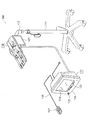
薬液シリンジ200は、図5に示すように、シリンダ部材210とピストン部材220からなり、シリンダ部材210にピストン部材220がスライド自在に挿入されている。シリンダ部材210は、円筒形の中空の本体部211を有しており、この本体部211の閉塞した先端面に導管部212が形成されている。
As shown in FIG. 5, the
シリンダ部材210の本体部211の末端面は開口されており、この開口から本体部211の内部にピストン部材220が挿入されている。シリンダ部材210の末端外周にはシリンダフランジ213が形成されており、ピストン部材220の末端外周にはピストンフランジ221が形成されている。
The end surface of the
本形態の薬液注入システム1000では、使用される薬液シリンジ200の少なくとも一部がプレフィルドタイプからなり、プレフィルドタイプの薬液シリンジ200では、シリンダ部材210に薬液が充填された状態で出荷される。
In the chemical
薬液シリンジ200のシリンダ部材210にはRFIDチップ214が装着されており、そのRFIDチップ214には、その薬液シリンジ200に関する、名称、プレフィルドタイプかリフィルタイプかの識別データ、個体ごとの識別データ、容量、シリンダ部材210の耐圧、シリンダ部材210の内径、ピストン部材220のストローク、などの各種データが記録されている。
An
さらに、その薬液シリンジ200がプレフィルドタイプの場合、そのRFIDチップ214には、充填されている薬液に関する、名称、成分、粘度、消費期限、CT用かMR用かなどの識別データ、などの各種データも設定されている。また、そのプレフィルドタイプの薬液シリンジ200に充填されている薬液が造影剤の場合、そのRFIDチップ214には、注入速度を時間経過により変化させる可変パターン、なども必要により設定されている。
Further, when the
なお、この薬液シリンジ200としては、薬液として造影剤が充填されている造影シリンジ200Cと、薬液として生理食塩水が充填されている生食シリンジ200Wと、があり、薬液注入装置100には、造影/生食シリンジ200C,Wが同時に装着される。
The
このように薬液注入装置100に装着された造影/生食シリンジ200C,Wは、例えば、二股の延長チューブ230などのシリンジ周辺機器で被験者に連結される。ただし、このようなシリンジ周辺機器にもRFIDチップ214が装着されており、そのRFIDチップ214にはシリンジ周辺機器の名称や耐圧などの各種データが記録されている。
The contrast /
本形態の薬液注入装置100は、図4に示すように、注入制御ユニット101と注入ヘッド110とが別体に形成されており、その注入制御ユニット101と注入ヘッド110とは通信ケーブル102で有線接続されている。
As shown in FIG. 4, the
注入ヘッド110は、装着される薬液シリンジ200を駆動して被験者に薬液を注入し、注入制御ユニット101は、注入ヘッド110を動作制御する。このため、図2に示すように、注入制御ユニット101はコンピュータユニット130が内蔵されており、MRI装置300の撮像制御ユニット302とも通信ネットワーク304で有線接続されている。
The
注入制御ユニット101は、メイン操作パネル103、データ表示手段であるメインタッチパネル104、スピーカユニット105、等が本体ハウジング106の前面に配置されており、別体のコントローラユニット107が接続コネクタ108で有線接続されている。
In the
注入ヘッド110は、キャスタスタンド111の上端に可動アーム112で装着されており、図4に示すように、そのヘッド本体113の上面には、薬液シリンジ200が着脱自在に装着される半円筒形の溝状の凹部114が形成されている。
The
この凹部114の前部には、薬液シリンジ200のシリンダフランジ211を着脱自在に保持するシリンダ保持機構116が形成されており、凹部114の後方には、ピストンフランジ221を保持してスライド移動させる薬液注入機構117が配置されている。
A
シリンダ保持機構116は、凹部114に異形の凹溝として形成されており、シリンダフランジ211が係脱自在に係合する。薬液注入機構117は、作動時にも磁界を発生しない超音波モータ118を駆動源として個々に有しており、ネジ機構(図示せず)などによりピストン部材220をスライド移動させる。また、薬液注入機構117にはロードセル118も個々に内蔵されており、そのロードセル118は、ピストン部材220を押圧する応力を検出する。
The
注入ヘッド110の2つの凹部114には、造影/生食シリンジ200C,Wが個々に装着されるので、これら2つの凹部114と2個の薬液注入機構117により、被験者に造影剤を注入する造影注入機構117Cと生理食塩水を注入する生食注入機構117Wとが形成されている。
Since the contrast /
薬液シリンジ200のシリンダフランジ213は、単純な円環形状ではなく、外縁に平行な二辺が形成された小判型に形成されており、シリンダ保持機構116は、薬液シリンジ200のシリンダフランジ213を回転不能に所定方向に保持するので、薬液シリンジ200は、上述のように保持されたときに上方および下方となる位置に一対のRFIDチップ214が個々に装着されている。
The
そして、注入ヘッド110の凹部114の所定位置には、RFIDリーダ122が配置されており、このRFIDリーダ122が凹部114に装着されてシリンダ保持機構116で保持された薬液シリンジ200のRFIDチップ214から各種データを取得する。
An
また、注入ヘッド110は、後部側面にデータ表示手段であるサブタッチパネル121とRFIDリーダであるRFIDリーダ122とが装着されており、このRFIDリーダ122が薬液シリンジ200や延長チューブ230などのRFIDチップ214から各種データを取得する。
The
なお、本形態の薬液注入装置100では、少なくとも注入ヘッド110の各部が非磁性体で形成されており、非磁性体で形成できない部分は防磁されている。例えば、超音波モータ118やロードセル119などは、燐青銅合金(Cu+Sn+P)、チタン合金(Ti-6Al-4V)、マグネシウム合金(Mg+Al+Zn)、などの非磁性体の金属で形成されており、ヘッド本体113などは非磁性体の樹脂で形成されている。
In the
本形態の薬液注入装置100は、図2に示すように、上述した各種デバイスがコンピュータユニット130に接続されており、このコンピュータユニット130が各種デバイスを統合制御する。コンピュータユニット130は、いわゆるワンチップマイコンからなり、CPU(Central
Processing Unit)131、ROM(Read Only Memory)132、RAM(Random Access Memory)133、I/F(Interface)134、等のハードウェアを有している。As shown in FIG. 2, in the
The hardware includes a processing unit (131), a ROM (Read Only Memory) 132, a RAM (Random Access Memory) 133, an I / F (Interface) 134, and the like.
コンピュータユニット130は、そのROM132などの情報記憶媒体に適切なコンピュータプログラムがファームウェアなどで実装されており、そのコンピュータプログラムに対応してCPU131が各種の処理動作を実行する。
In the
本形態の薬液注入装置100は、上述のように実装されているコンピュータプログラムに対応してコンピュータユニット130が動作することにより、図1に示すように、動作制御手段140、を論理的に有しており、この動作制御手段140が、確認記憶手段141、データ照合手段142、警告出力手段143、データ蓄積手段144、データ保持手段146、表示制御手段147、注入制御手段148、等の各種手段を論理的に有している。
The
動作制御手段140は、CPU131がROM132などに実装されているコンピュータプログラムとRFIDチップ214から取得された各種データとに対応して所定動作を実行する機能に相当し、確認記憶手段141、データ照合手段142、警告出力手段143、データ蓄積手段144、データ保持手段146、表示制御手段147、注入制御手段148、を有している。
The
確認記憶手段141は、CPU131がデータ認識するRAM133の記憶領域などに相当し、所定の確認条件をデータ記憶している。データ照合手段142は、データ記憶されている確認条件とRFIDチップ214から取得された各種データとを照合し、警告出力手段143は、照合結果に対応して確認警告を報知出力する。
The
より具体的には、RAM133には、使用できる薬液シリンジ200や延長チューブ230などの識別データが確認条件としてデータ登録されており、RFIDリーダ122で薬液シリンジ200や延長チューブ230のRFIDチップ214から各種データが取得されると、その取得された薬液シリンジ200や延長チューブ230などの識別データがRAM133に登録されている識別データと照合される。
More specifically, in the
これで取得された識別データが登録されていないと、“この製品は使用可能な機器として登録されておりません、使用可能か確認して下さい”などのガイダンスメッセージが確認警告としてメイン/サブタッチパネル104,121で表示出力されるとともにスピーカユニット105で音声出力される。
If the identification data obtained in this way is not registered, a guidance message such as “This product is not registered as a usable device, please check if it can be used” will be displayed as a confirmation warning. The sound is output from the
また、RAM133には、確認条件として現在日時が日々更新されてデータ保持されており、薬液シリンジ200のRFIDチップ214から消費期限がデータ取得されると、その消費期限と現在日時がデータ照合される。これで現在日時が消費期限を超過していると、“この製品は消費期限を過ぎています。新しい製品を使用して下さい”などのガイダンスメッセージが確認警告としてメイン/サブタッチパネル104,121で表示出力されるとともにスピーカユニット105で音声出力される。
In addition, the current date and time are updated and stored as data in the
さらに、プレフィルドタイプの薬液シリンジ200では、個体ごとの製造番号もRFIDチップ214に設定されているので、データ蓄積手段144は、注入ヘッド110に装填されて注入動作が実行されたプレフィルドタイプの薬液シリンジ200の製造番号をデータ記憶する。
Further, in the prefilled type
この場合、データ照合手段142は、データ記憶されている製造番号とRFIDチップ214からデータ取得された製造番号とを照合し、警告出力手段143は、照合された製造番号が一致すると“このプレフィルドシリンジは過去に使用されています。新しい製品を使用して下さい”などのガイダンスメッセージが確認警告としてメイン/サブタッチパネル104,121で表示出力されるとともにスピーカユニット105で音声出力される。
In this case, the
データ保持手段146は、RFIDチップ214から取得された各種データをデータ保持し、表示制御手段147は、保持された各種データをメイン/サブタッチパネル104,121にデータ表示させ、注入制御手段148は、保持された各種データに対応して薬液注入機構117を動作制御する。
The
より具体的には、薬液シリンジ200のRFIDチップ214には、その薬液シリンジ200の名称や耐圧や容量などの各種データと、その薬液シリンジ200に充填されている薬液の名称や成分や消費期限などの各種データとが記録されているので、これらの各種データがRAM133に一時保持されてメイン/サブタッチパネル104,121で表示出力される。
More specifically, the
また、薬液シリンジ200のRFIDチップ214に薬液注入機構117の制御データが設定されていた場合、その制御データがRAM133に保持され、CPU131は保持された制御データに対応して薬液注入機構117を動作制御する。例えば、造影シリンジ200CのRFIDチップ214に造影剤の注入速度を時間経過により変化させる可変パターンがデータ記録されていた場合、その可変パターンに対応してCPU131が造影注入機構117Cの動作速度を経時的に可変させる。
Further, when the control data of the chemical
さらに、薬液シリンジ200や延長チューブ230のRFIDチップ214に耐圧がデータ記録されていると、CPU131はロードセル119の検出応力に対応してRAM133にデータ保持された耐圧を超過しないように薬液注入機構117の動作を制御する。
Furthermore, the breakdown voltage to the
また、薬液シリンジ200のRFIDチップ214に容量がデータ記録されていると、CPU131はRAM133にデータ保持された容量に対応して薬液注入機構117の動作を制御する。さらに、造影シリンジ200Cと生食シリンジ200WのRFIDチップ214から薬液の識別データが取得されると、CPU131は造影注入機構117Cと生食注入機構117Wとを順番に作動させる。
When the capacity is recorded in the
上述のような薬液注入装置100の各種手段は、必要によりメイン/サブタッチパネル104,121などのハードウェアを利用して実現されるが、その主体はROM132等の情報記憶媒体に格納されたリソースおよびコンピュータプログラムに対応してハードウェアであるCPU131が機能することにより実現されている。
The various means of the
このようなコンピュータプログラムは、例えば、RFIDチップ214からRFIDリーダ122で各種データが取得されると、RAM133などにデータ記憶されている確認条件とRFIDチップ214から取得された各種データとを照合すること、その照合結果に対応してメイン/サブタッチパネル104,121のデータ表示などで確認警告を報知出力すること、装填されて注入動作が実行された薬液シリンジ200の製造番号をRAM133などにデータ記憶させること、そのデータ記憶されている製造番号とRFIDチップ214からデータ取得された製造番号とを照合すること、その照合結果に対応してメイン/サブタッチパネル104,121のデータ表示などで確認警告を報知出力すること、RFIDチップ214から取得された各種データをRAM133などにデータ保持させること、保持された各種データをメイン/サブタッチパネル104,121にデータ表示させること、保持された各種データに対応して薬液注入機構117を動作制御すること、等の処理動作をCPU131等に実行させるためのソフトウェアとしてRAM133等の情報記憶媒体に格納されている。
For example, when various types of data are acquired from the
[実施の形態の動作]
上述のような構成において、本形態の薬液注入装置100が使用される場合、図3に示すように、MRI装置300の撮像ユニット301の近傍に薬液注入装置100が配置され、使用する造影/生食シリンジ200C,Wや延長チューブ230などが用意される。[Operation of the embodiment]
In the configuration as described above, when the
つぎに、薬液注入装置100のメイン/サブタッチパネル104,121に“動作モードを選択して下さい。1.造影と生食を注入 2.造影のみ注入 3.生食のみ注入”などの動作モードの選択ガイダンスが表示出力されるので、その手動操作により切換入力された動作モードが薬液注入装置100にデータ設定される(ステップS1,S2)。
Next, select the operation mode on the main /
本形態の薬液注入装置100は、上述のように動作モードが切換入力されると造影シリンジ200Cや延長チューブ230などの使用機器がデータ設定されるので、その使用機器の全部のRFIDチップ214から各種データが取得されないと(ステップS3〜S10)、注入作業を開始しない(ステップS11〜)。
In the
例えば、動作モードとして“1.造影と生食を注入”が切換入力された場合、造影シリンジ200Cと生食シリンジ200Wと延長チューブ230と注入針(図示せず)とが使用機器としてデータ設定されるので、作業者は延長チューブ230と注入針とのRFIDチップ214を注入ヘッド110の側部のRFIDリーダ122に順番に対向させ、造影/生食シリンジ200C,Wを注入ヘッド110の造影/生食注入機構117C,Wに装着する。
For example, when “1. Inject contrast and saline” is input as an operation mode, the
すると、延長チューブ230などのRFIDチップ214が注入ヘッド110のRFIDリーダ122に対向されると、そのRFIDリーダ122によりRFIDチップ214から各種データが取得され(ステップS3)、コンピュータユニット130のRAM133にデータ登録されている確認条件とデータ照合される(ステップS4)。
Then, when the
このような確認条件としては、使用できる薬液シリンジ200や延長チューブ230などの識別データが登録されているので、RFIDチップ214から取得された識別データが確認条件としてデータ登録されていないと、“この製品は使用可能な機器として登録されておりません、使用可能か確認して下さい”などのガイダンスメッセージが確認警告としてメイン/サブタッチパネル104,121で表示出力されるとともにスピーカユニット105で音声出力される(ステップS5)。
As such confirmation conditions, since identification data such as the usable
また、造影/生食シリンジ200C,Wが注入ヘッド110の造影/生食注入機構117C,Wに適切に装着されると、そのRFIDリーダ122にRFIDチップ214が自動的に所定距離で対向されるので、そのRFIDチップ214からRFIDリーダ122に各種データが取得される(ステップS3)。
Further, when the contrast /
この場合も、取得データが確認条件とデータ照合され(ステップS4)、取得された識別データが確認条件としてデータ登録されていないと確認警告が報知出力されるが(ステップS5)、さらに、確認条件に整合しても使用機器が薬液シリンジ200であることが判定されると(ステップS6)、RFIDチップ214からデータ取得された製造番号とRAM133にデータ登録されている製造番号とがデータ照合される(ステップS7)。
Also in this case, the acquired data is collated with the confirmation condition (step S4), and if the acquired identification data is not registered as the confirmation condition, a confirmation warning is output (step S5). If it is determined that the device to be used is the
このように照合された製造番号が一致すると“このシリンジは過去に使用されています。新しい製品を使用して下さい”などのガイダンスメッセージが確認警告としてメイン/サブタッチパネル104,121とスピーカユニット105とで報知出力される(ステップS5)。 When the collated serial numbers match, a guidance message such as “This syringe has been used in the past. Please use a new product” is displayed as a confirmation warning. Is then output (step S5).
上述のようにして適切な使用機器のRFIDチップ214から薬液注入装置100に取得された各種データは、例えば、“これは〜(製造メーカ)製の延長チューブ〜(名称)です。耐圧〜、…”“〜(製造メーカ)製の造影シリンジ〜(名称)が装着されました。製造番号〜、薬液名称〜、薬液種別〜、容量〜、耐圧〜、…”などとしてメイン/サブタッチパネル104,121に表示出力される(ステップS8)。
The various data acquired from the
なお、RFIDチップ214には、データ表示の対象となる各種データと、対象とならない各種データとがデータ設定されているので、例えば、その各種データごとにデータ表示の有無が2値フラグでデータ設定されており、薬液注入装置100は、RFIDチップ214から取得された各種データから適切な一部をデータ表示する。
The
さらに、使用機器のRFIDチップ214から薬液注入装置100に取得された各種データに“耐圧”や“容量”や“造影剤の注入速度を時間経過により変化させる可変パターン”などの制御データが内包されていた場合、その制御データがコンピュータユニット130のRAM133に設定される(ステップS9)。RFIDチップ214から取得された各種データに制御データが設定されていなかった場合は、デフォルトの制御データが設定される。
Furthermore, control data such as “pressure resistance”, “capacity”, and “variable pattern that changes the contrast agent injection speed over time” are included in various data acquired from the
上述のように薬液注入装置100に装填された造影/生食シリンジ200C,Wが延長チューブ230で被験者に連結されてから、作業者によりメイン/サブタッチパネル104、121やメイン操作パネル103に作業開始が入力操作されると、これを検知した薬液注入装置100は(ステップS11)、作業開始をMRI装置300にデータ送信する(ステップS14)。
As described above, after the contrast /
図8に示すように、このように薬液注入装置100から作業開始をデータ受信したMRI装置300は(ステップT2)、作業開始を薬液注入装置100にデータ返信して撮像動作を実行する(ステップT8)。このため、本形態の透視撮像システム1000では、薬液注入装置100の薬液注入にMRI装置300の画像撮像が追従することになる。
As shown in FIG. 8, the
なお、本形態の透視撮像システム1000では、図6および図8に示すように、前述のように薬液注入装置100が準備完了の状態で(ステップS11〜S13)、MRI装置300に撮像開始が入力操作された場合も(ステップT1)、MRI装置300の画像撮像に薬液注入装置100の薬液注入が追従する(ステップT4,T6〜,S12,S18〜)。
In the
そして、本形態の薬液注入装置100では、図7に示すように、薬液注入の一連の作業を実行する場合(ステップS18〜)、その注入開始から経過時間が計測され(ステップS19)、その経過時間とRFIDチップ214から取得された制御データとに対応して造影注入機構117Cと生食注入機構117Wとがリアルタイムに順番に動作制御される(ステップS22)。
And in the
このため、造影シリンジ200CのRFIDチップ214に造影剤の注入速度を時間経過により変化させる可変パターンがデータ設定されていた場合、その可変パターンに対応して造影注入機構117Cの動作速度が経時的に可変される。同様に、生食シリンジ200WのRFIDチップ214に造影剤の注入完了に対応して生理食塩水の注入を開始させる注入パターンがデータ設定されていた場合、その注入パターンに対応して生食注入機構117Wが動作制御される。
For this reason, when a variable pattern for changing the injection speed of the contrast agent with the passage of time is set in the
また、動作モードとして“1.造影と生食を注入”がデータ設定されているときは、造影/生食注入機構117C,Wの両方が駆動されるが、“2.造影のみ注入”がデータ設定されているときは造影注入機構117Cのみ駆動され、“3.生食のみ注入”がデータ設定されているときは生食注入機構117Wのみ駆動される。
In addition, when “1. Inject contrast and saline” is set as the operation mode, both contrast /
さらに、上述のように薬液注入機構117が駆動されるとき、ロードセル119が検出する応力がコンピュータユニット130にリアルタイムにデータ取得される(ステップS20)。そして、RFIDチップ214から取得された薬液の粘度やシリンダ部材210の内径などに対応して、ロードセル119の検出応力から薬液の注入圧力が算出され(ステップS21)、この注入圧力がRFIDチップ214から取得された圧力範囲を満足するように薬液注入機構117がリアルタイムに動作制御される(ステップS23)。
Further, when the
このため、造影/生食シリンジ200C,Wや延長チューブ230のRFIDチップ214に耐圧がデータ設定されていた場合、その耐圧に対応して造影/生食注入機構117C,Wが動作制御される。なお、このような複数の使用機器の耐圧が相違する場合、当然ながら、最小の耐圧に対応して動作制御が実行されることになる。
For this reason, when the pressure resistance is set in the contrast /
なお、上述のように造影/生食注入機構117C,Wにより造影/生食シリンジ200C,Wが駆動されているときも、そのRFIDチップ214はRFIDリーダ122により常時検出されている(ステップS18)。そして、注入作業が完了する以前に(ステップS32)、上述の検出が中断されると(ステップS18)、造影/生食注入機構117C,Wによる注入動作が中止される(ステップS28)。
Even when the contrast /
さらに、“シリンジ脱落を検出しました。〜シリンジの装着を確認して下さい”などのガイダンスメッセージが確認警告としてメイン/サブタッチパネル104,121で表示出力されるとともにスピーカユニット105で音声出力され(ステップS26)、異常発生および注入中止がCTスキャナ300にデータ送信される(ステップS25,S28)。
In addition, a guidance message such as “Syringe omission detected. -Please confirm the syringe installation” is displayed and output as a confirmation warning on the main /
すると、CTスキャナ300は、異常発生をデータ受信すると(ステップT10)、その異常発生がガイダンス表示などで確認警告として報知出力され(ステップT16)、動作中止をデータ受信すると(ステップT13)、その撮像動作が中止される(ステップT18)。
Then, when the
なお、本形態の薬液注入装置100およびMRI装置300は、前述の準備完了の状態で異常発生が検出されたり(ステップS13,T3)、動作実行の最中に異常発生が検出されても(ステップS23,T9)、その異常発生が報知出力されるとともに(ステップS26,T16)、その動作中止が実行される(ステップS28,T18)。
It should be noted that the
さらに、その異常発生が他方にもデータ送信されるので(ステップS25,T15)、これをデータ受信した他方でも(ステップT10,S24)、やはり異常発生が報知出力される(ステップT16,S26)。また、一方の動作中止も他方にデータ送信されるので(ステップS27,T17)、これをデータ受信した他方でも(ステップT13,S31)、その動作中止が実行される(ステップT18,S28)。 Further, since the abnormality occurrence is also transmitted to the other side (steps S25, T15), the abnormality occurrence is also notified and output on the other side (steps T10, S24). In addition, since one operation stop is also transmitted to the other (steps S27, T17), the other operation that received the data (steps T13, S31) executes the operation stop (steps T18, S28).
なお、一方に動作中止が入力操作されたときも(ステップS29,T11)、その動作中止が実行されるとともに(ステップS28,T18)、他方にも送信されるので(ステップS27,T17)、これをデータ受信した他方でも(ステップT13,S31)、その動作中止が実行される(ステップT18,S28)。 When an operation stop is input on one side (steps S29 and T11), the operation stop is executed (steps S28 and T18) and also transmitted to the other side (steps S27 and T17). On the other side of receiving the data (steps T13 and S31), the operation is stopped (steps T18 and S28).
また、一方で動作完了が検出されたときも(ステップS32,T14)、その動作終了が実行されるとともに(ステップS33,T19)、その動作終了が他方にデータ送信されるので(ステップS34,T20)、これをデータ受信した他方でも(ステップT12,S31)、その動作中止が実行される(ステップT18,S28)。 When the operation completion is detected on the one hand (steps S32 and T14), the operation end is executed (steps S33 and T19), and the operation end is transmitted to the other side (steps S34 and T20). On the other hand, when the data is received (steps T12 and S31), the operation is stopped (steps T18 and S28).
本形態の薬液注入装置100では、上述のように注入動作が正常または異常に終了されると(ステップS33,S28)、薬液シリンジ200や延長チューブ230などの使用機器のRFIDチップ214から取得された識別データが確認条件としてRAM133にデータ登録される(ステップS36)。
In the
[実施の形態の効果]
本形態の薬液注入システム1000では、上述のように薬液シリンジ200に各種データが記録されているRFIDチップ214が装着されており、薬液注入装置100は、そのRFIDチップ214から各種データを取得し、その各種データの少なくとも一部に対応して所定動作を実行するので、薬液注入装置100に大容量データを容易に入力して各種動作を実行することができる。[Effect of the embodiment]
In the
さらに、本形態の薬液注入システム1000では、RFIDチップ214から取得された各種データの少なくとも一部をデータ保持してメイン/サブタッチパネル104,121に表示出力させるので、作業者は使用する薬液シリンジ200などの各種データを簡単かつ確実に確認することができる。
Furthermore, in the
しかも、本形態の薬液注入装置100は、注入ヘッド110の凹部114にRFIDリーダ122が配置されており、その凹部114に薬液シリンジ200が適切に装着されると、薬液シリンジ200のRFIDチップ214がRFIDリーダ122に対向する。
Moreover, in the
このため、薬液注入装置100に薬液シリンジ200を装填すると、そのRFIDチップ214がRFIDリーダ122に自動的に検出されるので、薬液シリンジ200のRFIDチップ214を簡単かつ確実に薬液注入装置100のRFIDリーダ122にデータ読取させることができる。
For this reason, when the
さらに、本形態の薬液注入装置100では、RFIDリーダ122がRFIDチップ214を検出しているときのみコンピュータユニット130が薬液注入機構117を動作可能とするので、薬液注入の最中に薬液シリンジ200が適切な位置から脱落したような場合、その薬液注入を自動的に中止させることができる。
Furthermore, in the
しかも、このように薬液シリンジ200の脱落を検出する機構が、薬液シリンジ200から薬液注入装置100に各種データを転送するためのRFIDチップ/リーダ214,122からなるので、専用のセンサ機構などを必要とすることなく簡単な構造で薬液シリンジ200の脱落を検出することができる。
In addition, since the mechanism for detecting the drop of the
一方、本形態の薬液注入装置100は、注入ヘッド110の側部にもRFIDリーダ122が配置されているので、注入ヘッド110に薬液シリンジ200を装着した状態などでも、延長チューブ230などのシリンジ周辺機器のRFIDチップ214の各種データを容易に取得することができる。
On the other hand, in the
特に、注入ヘッド110の側部にサブタッチパネル121が搭載されているので、作業者が注入ヘッド110の凹部114に薬液シリンジ200を装着したり、注入ヘッド110の側部のRFIDリーダ122に延長チューブ230を対向させると、その近傍のサブタッチパネル121に各種データが表示出力されることになり、使用する薬液シリンジ200などの各種データを簡単に直感的に確認することができる。
In particular, since the
しかも、RFIDチップ214から取得された各種データを表示出力するサブタッチパネル121は入力操作も受け付けるので、薬液注入装置100がRFIDチップ214から取得された各種データに対応して各種動作を実行するとき、その各種動作を作業者が所望により調節するようなことも簡単にできる。
In addition, since the
また、本形態の薬液注入装置100は、データ記憶している確認条件とRFIDチップ214から取得された各種データとを照合し、必要により確認警告を報知出力する。このため、例えば、その薬液注入装置100で使用できない薬液シリンジ200や、消費期限を超過した薬液シリンジ200などを使用しようとすると確認警告が報知出力されることになり、各種の医療ミスを良好に防止することができる。
Moreover, the
特に、本形態の薬液注入装置100では、薬液シリンジ200や延長チューブ230などのRFIDチップ214がデータ読取されると個体ごとの製造番号がデータ記憶され、新規にRFIDチップ214からデータ取得された製造番号がデータ記憶されていると確認警告が報知出力されるので、一度使用されると廃棄される薬液シリンジ200や延長チューブ230などが何度も使用される医療ミスなどを簡単かつ確実に防止することができる。
In particular, in the
さらに、本形態の薬液注入システム1000では、プレフィルドタイプの造影剤の薬液シリンジ200のRFIDチップ214に造影剤の注入速度を時間経過により変化させる可変パターンがデータ記録されていると、薬液注入装置100は、その可変パターンに対応して造影剤の注入速度を経時的に変化させる。
Furthermore, in the
従って、最適な造影度を良好に維持することができ、造影剤の注入容量を必要最小限として被験者の身体的な負担を低減することができる。それでいて、複雑な可変パターンを薬液注入装置100に事前にデータ登録しておく必要がなく、例えば、新規の造影剤に対応した新規の可変パターンでも簡単に薬液シリンジ200のRFIDチップ214から薬液注入装置100にデータ入力することができる。
Therefore, it is possible to maintain the optimum contrast level well, and to reduce the physical burden on the subject by reducing the injection volume of the contrast medium to the minimum necessary. Nevertheless, it is not necessary to register data in advance in the
また、本形態の薬液注入装置100は、薬液シリンジ200のピストン部材220を押圧する応力から薬液の注入圧力を検出し、その注入圧力が異常圧力となると確認警告を報知出力するとともに注入動作を強制停止させるので、異常な圧力で薬液が注入される医療ミスを防止することができる。
Moreover, the
なお、上述のように薬液注入装置100が薬液の圧力を検出するためには、薬液シリンジ200のピストン部材220を押圧する応力だけではなく、シリンダ部材210の内径や薬液の粘度などの各種データが必要となるが、このような各種データはRFIDチップ214により薬液注入装置100にデータ入力される。このため、本形態の薬液注入システム1000では、作業者が各種データを薬液注入装置100に手動入力する煩雑な作業を必要とすることなく、薬液シリンジ200ごと薬液ごとの注入圧力を薬液注入装置100が的確に検出することができる。
In addition, in order for the
しかも、本形態の薬液注入システム1000では、薬液シリンジ200だけではなく、延長チューブ230などのシリンジ周辺機器にもRFIDチップ214が装着されている。このため、薬液注入装置100が延長チューブ230の耐圧などにも対応して注入動作を制御することができ、薬液注入装置100では使用できない延長チューブ230が使用される医療ミスなども良好に防止することができる。
Moreover, in the
さらに、本形態の透視撮像システム1000では、薬液注入装置100の薬液注入とMRI装置300の画像撮像とが自動的に連動するので、造影剤と生理食塩水とが的確なタイミングで順番に注入される被験者から透視画像を的確なタイミングで撮像することができる。
Furthermore, in the
[実施の形態の変形例]
本発明は上記形態に限定されるものではなく、その要旨を逸脱しない範囲で各種の変形を許容する。例えば、上記形態では薬液シリンジ200が装填される注入ヘッド110にRFIDチップ214から各種データを取得するRFIDリーダ122と取得データを表示出力するサブタッチパネル121とが搭載されていることで、操作性が良好であることを例示した。[Modification of Embodiment]
The present invention is not limited to the above embodiment, and various modifications are allowed without departing from the scope of the present invention. For example, in the above embodiment, the
しかし、そのRFIDリーダ122やサブタッチパネル121が注入ヘッド110とは別個の位置に配置されていることも可能であり、RFIDリーダ122が別体のハンディユニットとして有線や無線で薬液注入装置100に接続されているようなことも可能である(図示せず)。
However, the
例えば、上記形態ではRFIDチップ/リーダ214,122の無線通信の有効距離を数センチと想定し、RFIDリーダ122にRFIDチップ214が間近に対向された場合のみデータ取得が実行されることを想定した。しかし、その無線通信の有効距離を数十センチとしておき、RFIDリーダ122を可動アーム112に装着して注入ヘッド110の近傍に配置するようなことも可能である(図示せず)。
For example, in the above embodiment, it is assumed that the effective wireless communication distance of the RFID chip /
この場合、注入ヘッド110に薬液シリンジ200を装着したり、その薬液シリンジ200に延長チューブ230を連結したりすると、そのRFIDチップ214が自動的にRFIDリーダ122と無線通信できる位置に配置される。また、このような構成では、1個のRFIDリーダ122が複数のRFIDチップ214と無線通信できるので、さらに構造を簡単とすることができる。
In this case, when the
また、上記形態では薬液シリンジ200のシリンダ部材210の外周面にRFIDチップ214が装着されていることを例示したが、例えば、このようなRFIDチップ214がピストン部材220の外側面や末端面に装着されていることも可能である(図示せず)。
In the above embodiment, the
さらに、上記形態では説明を簡単とするため、RFIDチップ214が装着されている薬液シリンジ200が、RFIDリーダ122が搭載されている薬液注入装置100に直接に装填されることを例示したが、現在の実際の薬液注入装置100は、最大サイズの薬液シリンジ200のみ直接に装填され、最大以外のサイズの薬液シリンジ200は各々に専用のシリンダアダプタ(図示せず)を介して装填される。
Furthermore, in order to simplify the description in the above embodiment, the
そこで、このシリンダアダプタにRFIDリーダ122を搭載しておき、シリンダアダプタを注入ヘッド110に装填すると、そのRFIDリーダ122が薬液注入装置100に接続されることも可能である(図示せず)。また、シリンダアダプタにもRFIDチップ214を搭載しておき、薬液シリンジ200をシリンダアダプタとともに注入ヘッド110に装填すると、そのRFIDリーダ122で薬液シリンジ200とシリンダアダプタとのRFIDチップ214がデータ検出されることも可能である(図示せず)。
Therefore, when the
また、上記形態では薬液シリンジ200などの使用を一度に制限するため、使用される薬液シリンジ200などのRFIDチップ214から個体ごとの製造番号を薬液注入装置100がRFIDリーダ122でデータ取得してデータ記憶し、新規にデータ取得された製造番号がデータ記憶されていると確認警告を報知出力することを例示した。
Further, in the above embodiment, in order to restrict the use of the
しかし、薬液シリンジ200などのRFIDチップ214をデータ追記が可能な製品としておき、薬液注入装置100が、装填されて注入動作が実行された薬液シリンジ200のRFIDチップ214に使用済をデータ記録し、新規の薬液シリンジ200のRFIDチップ214から使用済がデータ取得されると確認警告を報知出力することも可能である。
However, the
この場合、薬液注入装置100に膨大な製造番号をデータ保存しておく必要がないので、そのRAM133のオーバーフローなどを防止することができ、無用に大容量なRAM133などを搭載する必要もない。しかも、薬液注入装置100の記憶データが不正にリセットされても、薬液シリンジ200などの不正な繰り返し利用を防止することができる。
In this case, since it is not necessary to store a large number of production numbers in the
さらに、上記形態では薬液シリンジ200などのRFIDチップ214から薬液注入装置100に薬液注入の制御データなども取得され、その制御データに対応して薬液注入装置100が薬液注入を動作制御することのみを例示したが、薬液注入装置100が薬液シリンジ200などのRFIDチップ214から取得する制御データと、タッチパネル104,121や操作パネル103などから入力操作される制御データと、の組み合わせに対応して薬液注入を動作制御することも可能である。
Further, in the above embodiment, control data for chemical injection is also acquired from the
例えば、前述のように薬液シリンジ200のRFIDチップ214に薬液注入の経時的な可変パターンをデータ記録しておき、MRI装置300による撮像部位がタッチパネル104,121などで入力操作されると、その撮像部位に対応して可変パターンが調整されるようなことも可能である。
For example, as described above, a time-varying variable pattern of chemical liquid injection is recorded in the
また、上記形態では注入動作を終了して薬液シリンジ200のRFIDチップ214からデータ取得した製造番号をデータ登録した薬液注入装置100が各種動作を終了することを想定したが、例えば、上述のように注入動作と製造番号のデータ登録とを完了した薬液注入装置100が、RFIDリーダ122により造影/生食シリンジ200C,Wの取り外しを検出すると、対応する造影/生食注入機構117C,Wを自動的に最後尾の初期位置まで後退させることも可能である。
Further, in the above embodiment, it is assumed that the chemical
さらに、このように各種動作を完了して造影/生食注入機構117C,Wをホームポジションまで後退させた薬液注入装置100が、RFIDリーダ122により新規の造影/生食シリンジ200C,Wの装着を検出すると、対応する造影/生食注入機構117C,Wをピストン部材210を保持する待機位置まで自動的に前進させることも可能である。これらの場合、薬液シリンジ200を適切なタイミングで薬液注入装置100に着脱されることで、薬液注入機構117が自動的に適切な位置に配置されるので、この配置に特別な操作が必要なく、より利便性を向上させることができる。
Further, when the
さらに、上記形態では薬液シリンジ200や延長チューブ214にRFIDチップ214が装着されていることを例示したが、例えば、薬液シリンジ200のみにRFIDチップ214が装着されていることも可能であり、延長チューブ214以外のカテーテルや薬液ボトルなどの各種のシリンジ周辺機器にRFIDチップ214が装着されていることも可能である(図示せず)。
Furthermore, in the above embodiment, the
また、上記形態では薬液シリンジ200や延長チューブ214にRFIDチップ214が装着されていることを例示したが、例えば、被験者の腕部に装着されるリストバンド、被験者の各種データが表記されているカルテ用紙、等の被験者周辺具に、被験者の各種データが設定されたRFIDチップ214が装着されていることも可能である(図示せず)。
In the above embodiment, the
この場合、被験者の各種データを簡単に薬液注入装置100に入力できるので、例えば、被験者の体重や年齢などに対応して注入動作を制御するようなことが可能であり、その被験者の病気に関係ない薬液が注入されることを自動的に防止するようなことも可能である。
In this case, since various data of the subject can be easily input to the chemical
さらに、上記形態では薬液注入装置100にRFIDチップ214で薬液シリンジ200などの各種データを入力することを例示したが、例えば、このようなRFIDチップ214の入力データで薬液注入装置100のコンピュータプログラムやリソースをデータ更新することも可能である。
Furthermore, in the above embodiment, it is exemplified that various data such as the
また、上記形態では造影/生食注入機構117C,Wを有する薬液注入装置100が造影剤と生理食塩水とを注入することを例示したが、1個の薬液注入機構117で造影剤のみを注入する薬液注入装置や、3個以上の薬液注入機構117で3種類以上の薬液を注入する薬液注入装置なども実施可能である(図示せず)。
In the above embodiment, the
さらに、上記形態では透視撮像装置としてMRI装置300を使用し、薬液注入装置100がMR用の造影剤を注入することを例示したが、例えば、透視撮像装置としてCTスキャナやPET装置を使用し、それ用の造影剤を薬液注入装置が注入することも可能である。
Further, in the above embodiment, the
また、上記形態ではRAM133等に格納されているコンピュータプログラムに対応してCPU131が動作することにより、薬液注入装置100の各種機能として各種手段が論理的に実現されることを例示した。しかし、このような各種手段の各々を固有のハードウェアとして形成することも可能であり、一部をソフトウェアとしてRAM133等に格納するとともに一部をハードウェアとして形成することも可能である。
Moreover, in the said form, it was illustrated that various means are logically implement | achieved as various functions of the chemical | medical
さらに、上記形態では薬液シリンジ200や延長チューブ230のRFIDチップ214に製造メーカが各種データを記録しておくことを想定したが、例えば、薬液シリンジ200などを使用する病院などの医療現場で薬液シリンジ200などのRFIDチップ214に各種データを記録することも可能である。
Further, in the above embodiment, it is assumed that the manufacturer records various data in the
この場合、医療現場で薬液シリンジ200に所望データを付与することができるので、例えば、リフィルタイプの薬液シリンジ200に所望の薬液を充填するとき、その薬液の各種データをRFIDチップ214で記録するようなことが可能となる。このような場合でも、例えば、前述のように薬液シリンジ200の繰り返し利用を防止するための製造番号などは、RFIDチップ214に事前に固定的にデータ記録しておくことが好適である。
In this case, since desired data can be given to the
また、上記形態では薬液シリンジ200のRFIDチップ214から各種データを取得するRFIDリーダ122が薬液注入装置100に搭載されていることを例示したが、例えば、薬液シリンジ200を適温に保温する薬液保温装置にRFIDリーダ122が搭載されていることも可能である(図示せず)。
Moreover, although the RFID reader |
この場合、薬液保温装置がRFIDチップ214から取得された各種データに対応して保温動作を制御することで薬液を適温に保温することが可能であり、薬液保温装置がRFIDチップ214の記録データをRFIDリーダ122が搭載されていない薬液注入装置にデータ送信することも可能である。
In this case, the chemical solution warming device can keep the chemical solution at an appropriate temperature by controlling the warming operation corresponding to various data acquired from the
Claims (17)
前記薬液シリンジに各種データが記録されているRFID(Radio Frequency Identification)チップが装着されており、
前記薬液注入装置が、
前記RFIDチップから記録されている前記各種データを取得するRFIDリーダと、
取得された前記各種データの少なくとも一部に対応して所定動作を実行する動作制御手段と、
を有し、
前記薬液注入機構は、前記ピストン部材を押圧する圧力を得るための検出器を含み、
前記RFIDチップは、前記薬液シリンジの耐圧値データを含み、
前記動作制御手段は、前記RFIDチップから取得された前記各種データを保持するデータ保持手段と、保持された前記各種データの少なくとも一部に対応して前記薬液注入機構を動作制御する注入制御手段と、を有し、前記注入制御手段は、前記検出器によって得られた圧力が前記データ保持手段に保持された耐圧値データを超えないように前記薬液注入機構の動作を制御することを含むように構成されている薬液注入システム。 A chemical solution syringe in which a piston member is slidably inserted into a cylinder member filled with a chemical solution, and the cylinder member and the piston member of the chemical solution syringe that are loaded interchangeably are moved relative to each other by a chemical solution injection mechanism. A chemical injection device that has at least a chemical injection device for injecting the chemical into a subject ,
RFID (Radio Frequency Identification) chip in which various data before Symbol liquid syringe is recorded is mounted,
The chemical injection device is
An RFID reader for acquiring the various data recorded from the RFID chip;
Operation control means for executing a predetermined operation corresponding to at least a part of the acquired various data;
Have
The chemical injection mechanism includes a detector for obtaining a pressure for pressing the piston member,
The RFID chip includes pressure value data of the chemical syringe,
The operation control means includes data holding means for holding the various data acquired from the RFID chip, and injection control means for controlling the operation of the chemical solution injection mechanism in response to at least a part of the held various data. The injection control means includes controlling the operation of the chemical injection mechanism so that the pressure obtained by the detector does not exceed the pressure value data held in the data holding means. Configured chemical injection system.
前記動作制御手段が、前記RFIDチップから取得された前記各種データを保持するデータ保持手段と、保持された前記各種データの少なくとも一部を前記データ表示手段に表示出力させる表示制御手段と、を有している請求項1に記載の薬液注入システム。 The chemical injection device also has data display means for displaying and outputting various data,
The operation control means includes data holding means for holding the various data acquired from the RFID chip, and display control means for causing the data display means to display and output at least a part of the held various data. The chemical injection system according to claim 1.
前記動作制御手段が、前記可変パターンに対応して前記薬液注入機構の動作速度を経時的に変化させる請求項8に記載の薬液注入システム。The chemical solution injection system according to claim 8, wherein the operation control unit changes an operation speed of the chemical solution injection mechanism with time corresponding to the variable pattern.
前記動作制御手段が、装填されて注入動作が実行された前記薬液シリンジの前記製造番号をデータ記憶するデータ蓄積手段と、データ記憶されている前記製造番号と新規の前記製造番号とを照合するデータ照合手段と、照合された前記製造番号が一致すると確認警告を報知出力する警告出力手段と、を有している請求項1ないし10の何れか一項に記載の薬液注入システム。 At least the serial number of each chemical syringe is set in the RFID chip,
Data accumulating means for storing the manufacturing number of the drug solution syringe that has been loaded and the injection operation has been executed, and data for collating the manufacturing number stored in the data with the new manufacturing number The chemical solution injection system according to any one of claims 1 to 10, further comprising: a collating unit; and a warning output unit that outputs a confirmation warning when the collated manufacturing numbers match.
前記動作制御手段が、装填されて注入動作が実行された前記薬液シリンジのRFIDチップに使用済をデータ記録するデータ記録手段と、前記薬液シリンジのRFIDチップから使用済がデータ取得されると確認警告を報知出力する警告出力手段と、を有している請求項1ないし11の何れか一項に記載の薬液注入システム。 The RFID chip on which at least used data is recorded is attached to the chemical syringe,
The operation control means is a data recording means for recording used data in the RFID chip of the chemical syringe that has been loaded and the injection operation has been executed, and a confirmation warning when used data is acquired from the RFID chip of the chemical syringe The chemical | medical solution injection | pouring system as described in any one of Claim 1 thru | or 11 which has a warning output means to alert | report output.
前記シリンジ周辺機器にも各々の各種データが記録されているRFIDチップが装着されている請求項1ないし12の何れか一項に記載の薬液注入システム。 A hollow needle-like member that is inserted into the subject and causes the medicinal solution to flow, a syringe periphery including at least one of an extension tube that couples the needle-like member and the medicinal solution syringe to cause the medicinal solution to flow , a catheter, and a medicinal solution bottle We have equipment,
The chemical injection system according to any one of claims 1 to 12, wherein an RFID chip in which various types of data are recorded is also attached to the syringe peripheral device.
前記被験者周辺具にも前記被験者の各種データが記録されているRFIDチップが装着されている請求項1ないし13の何れか一項に記載の薬液注入システム。 It also has a subject peripheral tool including at least one of a wristband worn on the arm part of the subject and a medical record sheet on which various data of the subject are written,
The medicinal-solution injection system according to any one of claims 1 to 13, wherein an RFID chip in which various data of the subject is recorded is also attached to the subject peripheral tool.
前記薬液保温装置も、
前記RFIDチップから記録されている前記各種データを取得するRFIDリーダと、
取得された前記各種データの少なくとも一部に対応して所定動作を実行する動作制御手段と、
を有している請求項1ないし14の何れか一項に記載の薬液注入システム。 The chemical solution warming device that keeps the chemical solution of the loaded chemical solution syringe at a predetermined temperature by a heat retention execution mechanism is also provided separately from the chemical solution injection device,
The chemical heat retention device also
An RFID reader for acquiring the various data recorded from the RFID chip;
Operation control means for executing a predetermined operation corresponding to at least a part of the acquired various data;
The chemical injection system according to claim 1, comprising:
前記RFIDチップから記録されている前記各種データを取得するRFIDリーダと、
取得された前記各種データの少なくとも一部に対応して所定動作を実行する動作制御手段と、
を有している薬液注入装置。 A chemical injection device for a chemical injection system according to any one of claims 1 to 14,
An RFID reader for acquiring the various data recorded from the RFID chip;
Operation control means for executing a predetermined operation corresponding to at least a part of the acquired various data;
A chemical injection device.
前記RFIDチップから記録されている前記各種データを取得するRFIDリーダと、
取得された前記各種データの少なくとも一部に対応して所定動作を実行する動作制御手段と、
を有している薬液保温装置。 A chemical solution heat retention device for a chemical solution injection system according to claim 15,
An RFID reader for acquiring the various data recorded from the RFID chip;
Operation control means for executing a predetermined operation corresponding to at least a part of the acquired various data;
A chemical solution heat retention device.
Priority Applications (1)
| Application Number | Priority Date | Filing Date | Title |
|---|---|---|---|
| JP2006510688A JP5342109B2 (en) | 2004-03-03 | 2005-03-02 | Chemical injection system |
Applications Claiming Priority (4)
| Application Number | Priority Date | Filing Date | Title |
|---|---|---|---|
| JP2004059034 | 2004-03-03 | ||
| JP2004059034 | 2004-03-03 | ||
| PCT/JP2005/003498 WO2005084732A1 (en) | 2004-03-03 | 2005-03-02 | Medical solution injection system |
| JP2006510688A JP5342109B2 (en) | 2004-03-03 | 2005-03-02 | Chemical injection system |
Related Child Applications (4)
| Application Number | Title | Priority Date | Filing Date |
|---|---|---|---|
| JP2011092107A Division JP5186577B2 (en) | 2004-03-03 | 2011-04-18 | Chemical injection system |
| JP2011282390A Division JP5465711B2 (en) | 2004-03-03 | 2011-12-22 | Method of operating the chemical injection system |
| JP2011282391A Division JP5600666B2 (en) | 2004-03-03 | 2011-12-22 | Method of operating the chemical injection system |
| JP2012212771A Division JP5743991B2 (en) | 2004-03-03 | 2012-09-26 | Chemical injection system |
Publications (2)
| Publication Number | Publication Date |
|---|---|
| JPWO2005084732A1 JPWO2005084732A1 (en) | 2007-11-29 |
| JP5342109B2 true JP5342109B2 (en) | 2013-11-13 |
Family
ID=34917956
Family Applications (7)
| Application Number | Title | Priority Date | Filing Date |
|---|---|---|---|
| JP2006510688A Active JP5342109B2 (en) | 2004-03-03 | 2005-03-02 | Chemical injection system |
| JP2011092107A Active JP5186577B2 (en) | 2004-03-03 | 2011-04-18 | Chemical injection system |
| JP2011282391A Active JP5600666B2 (en) | 2004-03-03 | 2011-12-22 | Method of operating the chemical injection system |
| JP2011282390A Active JP5465711B2 (en) | 2004-03-03 | 2011-12-22 | Method of operating the chemical injection system |
| JP2012212771A Active JP5743991B2 (en) | 2004-03-03 | 2012-09-26 | Chemical injection system |
| JP2013149770A Active JP5802713B2 (en) | 2004-03-03 | 2013-07-18 | Chemical injection system |
| JP2014176945A Pending JP2014221430A (en) | 2004-03-03 | 2014-09-01 | Drug solution injection system |
Family Applications After (6)
| Application Number | Title | Priority Date | Filing Date |
|---|---|---|---|
| JP2011092107A Active JP5186577B2 (en) | 2004-03-03 | 2011-04-18 | Chemical injection system |
| JP2011282391A Active JP5600666B2 (en) | 2004-03-03 | 2011-12-22 | Method of operating the chemical injection system |
| JP2011282390A Active JP5465711B2 (en) | 2004-03-03 | 2011-12-22 | Method of operating the chemical injection system |
| JP2012212771A Active JP5743991B2 (en) | 2004-03-03 | 2012-09-26 | Chemical injection system |
| JP2013149770A Active JP5802713B2 (en) | 2004-03-03 | 2013-07-18 | Chemical injection system |
| JP2014176945A Pending JP2014221430A (en) | 2004-03-03 | 2014-09-01 | Drug solution injection system |
Country Status (5)
| Country | Link |
|---|---|
| US (3) | US7967778B2 (en) |
| EP (1) | EP1723977B1 (en) |
| JP (7) | JP5342109B2 (en) |
| CN (3) | CN103143079B (en) |
| WO (1) | WO2005084732A1 (en) |
Families Citing this family (99)
| Publication number | Priority date | Publication date | Assignee | Title |
|---|---|---|---|---|
| US6663602B2 (en) | 2000-06-16 | 2003-12-16 | Novo Nordisk A/S | Injection device |
| DK1804865T3 (en) | 2004-10-21 | 2010-02-01 | Novo Nordisk As | Down-turning adjustment mechanism for a pen with spring pull-up |
| US20060211989A1 (en) | 2005-03-04 | 2006-09-21 | Rhinehart Edward J | Fluid delivery systems, devices and methods for delivery of fluids |
| AU2007216607A1 (en) * | 2005-04-06 | 2007-09-20 | Mallinckrodt Inc. | Systems and methods for managing information relating to medical fluids and containers therefor |
| CN101185610A (en) | 2005-04-06 | 2008-05-28 | 马林克罗特公司 | Systems and methods for managing information relating to medical fluids and containers therefor |
| WO2006114396A1 (en) | 2005-04-24 | 2006-11-02 | Novo Nordisk A/S | Injection device |
| US8211057B2 (en) * | 2005-09-12 | 2012-07-03 | Nemoto Kyorindo Co., Ltd. | Chemical liquid injection system |
| EA013338B1 (en) * | 2005-12-05 | 2010-04-30 | Чжуншань Ботай Фармасьютик Инструментс Ко., Лтд. | An automatic syringe |
| CN101400394B (en) | 2006-03-10 | 2012-07-04 | 诺沃-诺迪斯克有限公司 | An injection device having a gearing arrangement |
| EP1996259B1 (en) | 2006-03-10 | 2012-08-15 | Novo Nordisk A/S | An injection device and a method of changing a cartridge in the device |
| WO2007116862A1 (en) * | 2006-04-05 | 2007-10-18 | Nemoto Kyorindo Co., Ltd. | Medicinal-liquid injection device |
| JP2007275303A (en) * | 2006-04-06 | 2007-10-25 | Nemoto Kyorindo:Kk | Medicine liquid injection system |
| WO2007114447A1 (en) * | 2006-04-06 | 2007-10-11 | Nemoto Kyorindo Co., Ltd. | Medical liquid injecting device |
| DE602007004972D1 (en) | 2006-05-16 | 2010-04-08 | Novo Nordisk As | GEARING MECHANISM FOR AN INJECTION DEVICE |
| AU2007253481B2 (en) | 2006-05-18 | 2013-01-17 | Novo Nordisk A/S | An injection device with mode locking means |
| CN101466421B (en) * | 2006-06-14 | 2012-06-20 | 阿西斯特医疗系统有限公司 | Fluid purge in a medical injection system |
| EP1867356A1 (en) * | 2006-06-16 | 2007-12-19 | Swiss Medical Care | System for the injection of contrast agents |
| CN101516421B (en) | 2006-09-29 | 2012-11-28 | 诺沃-诺迪斯克有限公司 | An injection device with electronic detecting means |
| AU2007348611A1 (en) * | 2006-10-16 | 2008-09-12 | Alcon Research, Ltd. | Method of operating ophthalmic hand piece with disposable end |
| JP4892564B2 (en) * | 2006-12-07 | 2012-03-07 | 株式会社根本杏林堂 | Chemical injection device |
| JP4956219B2 (en) * | 2007-02-19 | 2012-06-20 | 株式会社根本杏林堂 | Chemical injection tool and chemical injection device |
| JP4956220B2 (en) * | 2007-02-19 | 2012-06-20 | 株式会社根本杏林堂 | Chemical injection tool and chemical injection device |
| BRPI0809265A2 (en) | 2007-03-23 | 2014-10-07 | Novo Nordisk As | INJECTION DEVICE INCLUDING A TIGHTENING NUT |
| JP5249210B2 (en) * | 2007-05-30 | 2013-07-31 | 株式会社根本杏林堂 | Chemical injection device, fluoroscopic imaging system, computer program |
| CN101315728B (en) * | 2007-05-31 | 2010-09-22 | 中国科学院自动化研究所 | Universal input device based on radio frequency recognition principle |
| JP5296683B2 (en) * | 2007-07-17 | 2013-09-25 | 株式会社根本杏林堂 | Chemical injection device, fluoroscopic imaging system, computer program |
| WO2009024562A1 (en) * | 2007-08-17 | 2009-02-26 | Novo Nordisk A/S | Medical device with value sensor |
| WO2009025996A1 (en) * | 2007-08-23 | 2009-02-26 | Mallinckrodt Inc. | Syringe content detection using rf energy |
| CN101868266B (en) * | 2007-11-19 | 2015-01-07 | 马林克罗特有限公司 | Fluid delivery system with multi-dose fluid source |
| ATE555822T1 (en) | 2007-12-31 | 2012-05-15 | Novo Nordisk As | ELECTRONICALLY MONITORED INJECTION DEVICE |
| EP2240784B1 (en) * | 2007-12-31 | 2013-07-31 | Oridion Medical (1987) Ltd. | Tube verifier |
| WO2009157165A1 (en) * | 2008-06-24 | 2009-12-30 | 株式会社根本杏林堂 | Medical fluid injecting device, fluoroscopic radiography system having the medical fluid injecting device, computer program for medical fluid injecting device, and data processing method |
| ES2398083T3 (en) * | 2008-08-19 | 2013-03-13 | Mallinckrodt, Inc. | Automatic injector with rf sensor for the detection of a pre-filled syringe |
| CN101952829B (en) | 2008-08-22 | 2015-09-16 | 利贝尔-弗拉施姆有限公司 | There is the power injector of decay constant functionality |
| JP5215084B2 (en) * | 2008-08-27 | 2013-06-19 | 株式会社根本杏林堂 | Chemical injection device, fluoroscopic imaging system having this chemical injection device, computer program of chemical injection device, and data processing method |
| WO2010065726A2 (en) * | 2008-12-05 | 2010-06-10 | Mallinckrodt Inc. | Inductively coupled injector faceplate |
| US20100146587A1 (en) * | 2008-12-09 | 2010-06-10 | Ecolab Inc. | Authentication of controlled dosing processes |
| WO2010107051A1 (en) * | 2009-03-18 | 2010-09-23 | 株式会社根本杏林堂 | Medicinal liquid injection device |
| EP2481430B1 (en) | 2009-04-08 | 2016-06-22 | Liebel-Flarsheim Company LLC | Medical fluid delivery system with reusable RFID fixture |
| ES2550631T3 (en) * | 2009-04-09 | 2015-11-11 | Liebel-Flarsheim Company Llc | Medical fluid delivery system with wand equipped with RFID |
| US9051163B2 (en) * | 2009-10-06 | 2015-06-09 | Ecolab Inc. | Automatic calibration of chemical product dispense systems |
| US8394053B2 (en) * | 2009-11-06 | 2013-03-12 | Crisi Medical Systems, Inc. | Medication injection site and data collection system |
| US8945066B2 (en) | 2009-11-06 | 2015-02-03 | Crisi Medical Systems, Inc. | Medication injection site and data collection system |
| CN102686254B (en) * | 2009-11-09 | 2014-08-06 | 株式会社根本杏林堂 | One-way valve with opening function, tube unit provided with the one-way valve, and drug solution injection system |
| US9870492B2 (en) * | 2010-01-22 | 2018-01-16 | Sanofi-Aventis Deutschland Gmbh | Method and system for determining information related to a drug reservoir |
| US9101534B2 (en) | 2010-04-27 | 2015-08-11 | Crisi Medical Systems, Inc. | Medication and identification information transfer apparatus |
| US8702674B2 (en) | 2010-04-27 | 2014-04-22 | Crisi Medical Systems, Inc. | Medication and identification information transfer apparatus |
| US8328082B1 (en) * | 2010-05-30 | 2012-12-11 | Crisi Medical Systems, Inc. | Medication container encoding, verification, and identification |
| US9514131B1 (en) * | 2010-05-30 | 2016-12-06 | Crisi Medical Systems, Inc. | Medication container encoding, verification, and identification |
| US10492991B2 (en) | 2010-05-30 | 2019-12-03 | Crisi Medical Systems, Inc. | Medication container encoding, verification, and identification |
| CA2799775C (en) | 2010-06-04 | 2020-03-24 | Medrad, Inc. | System and method for planning and monitoring multi-dose radiopharmaceutical usage on radiopharmaceutical injectors |
| US8606596B1 (en) | 2010-06-27 | 2013-12-10 | Crisi Medical Systems, Inc. | Medication waste and data collection system |
| US9078809B2 (en) | 2011-06-16 | 2015-07-14 | Crisi Medical Systems, Inc. | Medication dose preparation and transfer system |
| US10293107B2 (en) | 2011-06-22 | 2019-05-21 | Crisi Medical Systems, Inc. | Selectively Controlling fluid flow through a fluid pathway |
| US9744298B2 (en) | 2011-06-22 | 2017-08-29 | Crisi Medical Systems, Inc. | Selectively controlling fluid flow through a fluid pathway |
| US20140224829A1 (en) | 2011-09-21 | 2014-08-14 | Bayer Medical Care Inc. | Continuous Multi-Fluid Delivery System and Method |
| RU2017130667A (en) * | 2011-11-02 | 2019-02-05 | Санофи-Авентис Дойчланд Гмбх | PISTON FOR CARTRIDGE USED IN THE DEVICE FOR DELIVERY OF THE MEDICINE |
| JP6069351B2 (en) | 2011-12-29 | 2017-02-01 | ノボ・ノルデイスク・エー/エス | Torsion spring type automatic syringe with dial-up / dial-down administration mechanism |
| US9446190B2 (en) * | 2012-03-09 | 2016-09-20 | Medtech Systems Inc. | Hypodermic needle assembly and related methods |
| WO2013177527A1 (en) | 2012-05-25 | 2013-11-28 | Acist Medical Systems, Inc. | Fluid flow measurement systems and methods |
| CN102847209B (en) * | 2012-08-29 | 2016-01-20 | 深圳市好克光电仪器有限公司 | Syringe recognition system and syringe pump |
| CN104602736B (en) | 2012-09-05 | 2018-04-20 | E3D农业合作协会有限公司 | Electronics automatic injection device |
| CA2928460C (en) | 2012-10-30 | 2021-10-19 | Truinject Medical Corp. | System for injection training |
| US9792836B2 (en) | 2012-10-30 | 2017-10-17 | Truinject Corp. | Injection training apparatus using 3D position sensor |
| US10143830B2 (en) | 2013-03-13 | 2018-12-04 | Crisi Medical Systems, Inc. | Injection site information cap |
| US20140275990A1 (en) * | 2013-03-15 | 2014-09-18 | Soma Access Systems, Llc | Ultrasound Guidance System Including Tagged Probe Assembly |
| AU2014326970B2 (en) * | 2013-09-24 | 2019-06-20 | Kpr U.S., Llc | Feeding set and enteral feeding pump |
| US20150112315A1 (en) * | 2013-10-22 | 2015-04-23 | International Business Machines Corporation | Controlling access to an intravenous catheter |
| EP3111438B1 (en) | 2014-01-17 | 2018-12-19 | Truinject Medical Corp. | Injection site training system |
| US10290231B2 (en) | 2014-03-13 | 2019-05-14 | Truinject Corp. | Automated detection of performance characteristics in an injection training system |
| MX2017004528A (en) | 2014-10-10 | 2017-06-07 | Becton Dickinson Co | Substrate tensioning control device. |
| CA2961637C (en) | 2014-10-10 | 2019-02-26 | Becton, Dickinson And Company | Syringe labeling device |
| US9199033B1 (en) | 2014-10-28 | 2015-12-01 | Bayer Healthcare Llc | Self-orienting syringe and syringe interface |
| CN107106761B (en) | 2014-10-28 | 2020-11-03 | 拜耳医药保健有限公司 | Self-orienting pressure jacket and interface of pressure jacket to syringe |
| CN107106764B (en) | 2014-10-28 | 2020-10-16 | 拜耳医药保健有限公司 | Self-orienting pressure jacket and pressure jacket to syringe interface |
| NO2689315T3 (en) | 2014-10-28 | 2018-04-14 | ||
| KR20170102233A (en) | 2014-12-01 | 2017-09-08 | 트루인젝트 코프 | Injection training tool emitting omnidirectional light |
| CA3207200A1 (en) | 2015-01-09 | 2016-07-14 | Bayer Healthcare Llc | Multiple fluid delivery system with multi-use disposable set and features thereof |
| RS60247B1 (en) * | 2015-03-04 | 2020-06-30 | Sodastream Ind Ltd | Dosing system |
| KR20180012758A (en) * | 2015-05-27 | 2018-02-06 | 바이엘 헬쓰케어 엘엘씨 | Fluid Injection System and Features |
| JP6795504B2 (en) * | 2015-09-04 | 2020-12-02 | テルモ株式会社 | Syringe pump |
| WO2017070391A2 (en) * | 2015-10-20 | 2017-04-27 | Truinject Medical Corp. | Injection system |
| EP3374002A1 (en) | 2015-11-13 | 2018-09-19 | Bayer Healthcare LLC | Nested syringe assembly |
| WO2017151441A2 (en) | 2016-02-29 | 2017-09-08 | Truinject Medical Corp. | Cosmetic and therapeutic injection safety systems, methods, and devices |
| EP3423972A1 (en) | 2016-03-02 | 2019-01-09 | Truinject Corp. | Sensory enhanced environments for injection aid and social training |
| WO2017151716A1 (en) | 2016-03-02 | 2017-09-08 | Truinject Medical Corp. | System for determining a three-dimensional position of a testing tool |
| JP2016122466A (en) * | 2016-03-04 | 2016-07-07 | 株式会社根本杏林堂 | Liquid medicine injection device, system, control device, program, and processing method |
| JP7204639B2 (en) * | 2016-08-17 | 2023-01-16 | ソウホニー,ニシャ | Injection monitoring device and system |
| CN106345005A (en) * | 2016-10-27 | 2017-01-25 | 浙江理工大学 | Infusion monitoring system based on RFID (Radio Frequency Identification Device) technology and infusion monitoring method |
| JP6949486B2 (en) * | 2016-12-27 | 2021-10-13 | 株式会社 みずほ銀行 | Information management system, information management method and information management program |
| US10650703B2 (en) | 2017-01-10 | 2020-05-12 | Truinject Corp. | Suture technique training system |
| WO2018136901A1 (en) | 2017-01-23 | 2018-07-26 | Truinject Corp. | Syringe dose and position measuring apparatus |
| ES2871812T3 (en) * | 2017-03-16 | 2021-11-02 | Novartis Ag | Injector device |
| US11819672B2 (en) * | 2017-12-08 | 2023-11-21 | Nemoto Kyorindo Co., Ltd. | Chemical liquid injector |
| JP6467074B2 (en) * | 2018-01-17 | 2019-02-06 | 株式会社根本杏林堂 | Chemical injection device, fluoroscopic imaging system, computer program |
| US11191893B2 (en) | 2018-01-31 | 2021-12-07 | Bayer Healthcare Llc | System and method for syringe engagement with injector |
| JP7348916B2 (en) | 2018-05-23 | 2023-09-21 | アシスト・メディカル・システムズ,インコーポレイテッド | Flow measurement using image data |
| JP7328047B2 (en) | 2019-07-25 | 2023-08-16 | 朝日インテック株式会社 | chemical injector |
| US11633534B2 (en) | 2020-08-18 | 2023-04-25 | Acist Medical Systems, Inc. | Angiogram injections using electrocardiographic synchronization |
Citations (4)
| Publication number | Priority date | Publication date | Assignee | Title |
|---|---|---|---|---|
| JP2002518108A (en) * | 1998-06-15 | 2002-06-25 | メドラッド インコーポレイテッド | Encoding syringe information |
| WO2003024385A1 (en) * | 2001-09-12 | 2003-03-27 | Terumo Kabushiki Kaisha | Medicine container and medicine injector comprising the same |
| JP2003220136A (en) * | 2002-01-30 | 2003-08-05 | Nemoto Kyorindo:Kk | Medicine-injecting device, syringe adapter, injection head |
| JP2003290343A (en) * | 2002-04-02 | 2003-10-14 | Nemoto Kyorindo:Kk | Medical solution injection apparatus |
Family Cites Families (36)
| Publication number | Priority date | Publication date | Assignee | Title |
|---|---|---|---|---|
| US4854324A (en) * | 1984-01-31 | 1989-08-08 | Medrad, Inc. | Processor-controlled angiographic injector device |
| JP2717808B2 (en) * | 1988-08-10 | 1998-02-25 | テルモ株式会社 | Syringe pump |
| JP2849396B2 (en) * | 1989-02-28 | 1999-01-20 | 株式会社日立メディコ | X-ray CT imaging system |
| JPH03247348A (en) * | 1990-02-23 | 1991-11-05 | Shibuya Kogyo Co Ltd | Apparatus for detecting abnormality of syringe pump |
| US5383858B1 (en) | 1992-08-17 | 1996-10-29 | Medrad Inc | Front-loading medical injector and syringe for use therewith |
| JPH06277283A (en) | 1993-03-30 | 1994-10-04 | Sharp Corp | Infusion device |
| US6397098B1 (en) * | 1994-09-21 | 2002-05-28 | Medrad, Inc. | Data communication and control for medical imaging systems |
| JPH08126634A (en) * | 1994-10-30 | 1996-05-21 | Medeitetsukusu:Kk | Image display of three-dimensional (stereoscopic) or four-dimensional (three dimensions having time axis) data in stereoscopic imaging centering around blood vessel angiography utilizing x-rays |
| GB9422082D0 (en) * | 1994-11-02 | 1994-12-21 | Zeneca Ltd | Reservoirs and delivery devices |
| US5573515A (en) * | 1995-04-20 | 1996-11-12 | Invasatec, Inc. | Self purging angiographic injector |
| EP1380261B1 (en) * | 1995-04-20 | 2008-03-05 | ACIST Medical Systems, Inc. | Radiographic contrast material injector |
| US5653938A (en) | 1995-04-26 | 1997-08-05 | O. R. Solutions, Inc. | Method and apparatus for ensuring sterility of surgical drapes used with surgical equipment |
| US5687208A (en) * | 1995-10-06 | 1997-11-11 | Bhb General Partnership | Method of and apparatus for predicting computed tomography contrast enhancement with feedback |
| US5868710A (en) * | 1996-11-22 | 1999-02-09 | Liebel Flarsheim Company | Medical fluid injector |
| US6743202B2 (en) * | 1998-06-15 | 2004-06-01 | Medrad, Inc. | Encoding of syringe information |
| US7933780B2 (en) | 1999-10-22 | 2011-04-26 | Telaric, Llc | Method and apparatus for controlling an infusion pump or the like |
| AU2000231912A1 (en) * | 2000-03-15 | 2001-09-24 | Hitachi Ltd. | Medical information managing system |
| AUPQ867900A0 (en) | 2000-07-10 | 2000-08-03 | Medrad, Inc. | Medical injector system |
| US6740059B2 (en) | 2000-09-08 | 2004-05-25 | Insulet Corporation | Devices, systems and methods for patient infusion |
| IL156245A0 (en) * | 2000-12-22 | 2004-01-04 | Dca Design Int Ltd | Drive mechanism for an injection device |
| DE60235964D1 (en) * | 2001-02-22 | 2010-05-27 | Terumo Corp | SYRINGE PUMP |
| JP4754078B2 (en) | 2001-02-23 | 2011-08-24 | テルモ株式会社 | Syringe pump and liquid feeding method |
| FR2822048B1 (en) * | 2001-03-19 | 2003-09-26 | Ge Med Sys Global Tech Co Llc | METHOD OF CARDIAC RADIOLOGICAL EXAMINATION IN CORONAROGRAPHY AND DEVICE FOR IMPLEMENTING SAME |
| US7299981B2 (en) * | 2001-05-21 | 2007-11-27 | Scott Laboratories, Inc. | Smart supplies, components and capital equipment |
| US7308300B2 (en) * | 2001-05-30 | 2007-12-11 | Acist Medical Systems, Inc. | Medical injection system |
| JP2002355258A (en) * | 2001-06-01 | 2002-12-10 | Senko Medical Instr Mfg Co Ltd | Operation article with recognition tag and operation article recognizer |
| US20030040700A1 (en) * | 2001-07-31 | 2003-02-27 | Scott Laboratories, Inc. | Apparatuses and methods for providing IV infusion administration |
| JP2003070911A (en) | 2001-09-04 | 2003-03-11 | Suugan Kk | Syringe and injector head |
| EP1436029A4 (en) * | 2001-09-24 | 2009-12-30 | Scott Lab Inc | Methods and apparatuses for assuring quality and safety of drug administration and medical products and kits |
| JP2003250343A (en) | 2002-02-28 | 2003-09-09 | Tokyo Autom Mach Works Ltd | Water-holding bag for flowing plant and method for forming the same |
| JP4044780B2 (en) * | 2002-04-02 | 2008-02-06 | 株式会社根本杏林堂 | Injection head |
| WO2003097156A1 (en) | 2002-05-16 | 2003-11-27 | Scott Laborotories Inc. | Kits of medical supplies for sedation and analgesia |
| US7018361B2 (en) * | 2002-06-14 | 2006-03-28 | Baxter International Inc. | Infusion pump |
| US20040051368A1 (en) * | 2002-09-17 | 2004-03-18 | Jimmy Caputo | Systems and methods for programming pumps |
| JP2005074065A (en) * | 2003-09-02 | 2005-03-24 | Nemoto Kyorindo:Kk | Medicinal solution injection apparatus |
| US8405467B2 (en) | 2007-11-27 | 2013-03-26 | Qualcomm Incorporated | Methods and apparatuses for inductor tuning in radio frequency integrated circuits |
-
2005
- 2005-03-02 CN CN201210579393.7A patent/CN103143079B/en not_active Expired - Fee Related
- 2005-03-02 CN CN200580006572XA patent/CN1925885B/en not_active Expired - Fee Related
- 2005-03-02 JP JP2006510688A patent/JP5342109B2/en active Active
- 2005-03-02 CN CN201610115869.XA patent/CN105641776B/en active Active
- 2005-03-02 EP EP05719813.7A patent/EP1723977B1/en active Active
- 2005-03-02 WO PCT/JP2005/003498 patent/WO2005084732A1/en active Application Filing
- 2005-03-02 US US10/598,536 patent/US7967778B2/en active Active
-
2011
- 2011-04-18 JP JP2011092107A patent/JP5186577B2/en active Active
- 2011-06-27 US US13/169,497 patent/US9028446B2/en active Active
- 2011-12-22 JP JP2011282391A patent/JP5600666B2/en active Active
- 2011-12-22 JP JP2011282390A patent/JP5465711B2/en active Active
-
2012
- 2012-09-26 JP JP2012212771A patent/JP5743991B2/en active Active
-
2013
- 2013-07-18 JP JP2013149770A patent/JP5802713B2/en active Active
-
2014
- 2014-09-01 JP JP2014176945A patent/JP2014221430A/en active Pending
-
2015
- 2015-04-24 US US14/695,868 patent/US20150224250A1/en not_active Abandoned
Patent Citations (4)
| Publication number | Priority date | Publication date | Assignee | Title |
|---|---|---|---|---|
| JP2002518108A (en) * | 1998-06-15 | 2002-06-25 | メドラッド インコーポレイテッド | Encoding syringe information |
| WO2003024385A1 (en) * | 2001-09-12 | 2003-03-27 | Terumo Kabushiki Kaisha | Medicine container and medicine injector comprising the same |
| JP2003220136A (en) * | 2002-01-30 | 2003-08-05 | Nemoto Kyorindo:Kk | Medicine-injecting device, syringe adapter, injection head |
| JP2003290343A (en) * | 2002-04-02 | 2003-10-14 | Nemoto Kyorindo:Kk | Medical solution injection apparatus |
Also Published As
| Publication number | Publication date |
|---|---|
| WO2005084732A1 (en) | 2005-09-15 |
| EP1723977A1 (en) | 2006-11-22 |
| JP5600666B2 (en) | 2014-10-01 |
| JPWO2005084732A1 (en) | 2007-11-29 |
| JP5465711B2 (en) | 2014-04-09 |
| CN105641776A (en) | 2016-06-08 |
| JP2012250101A (en) | 2012-12-20 |
| JP5743991B2 (en) | 2015-07-01 |
| CN1925885B (en) | 2013-02-13 |
| JP2013212422A (en) | 2013-10-17 |
| US20150224250A1 (en) | 2015-08-13 |
| US7967778B2 (en) | 2011-06-28 |
| EP1723977A4 (en) | 2012-08-01 |
| JP5186577B2 (en) | 2013-04-17 |
| JP2012081314A (en) | 2012-04-26 |
| CN105641776B (en) | 2021-03-30 |
| CN1925885A (en) | 2007-03-07 |
| US20110284577A1 (en) | 2011-11-24 |
| CN103143079B (en) | 2016-09-28 |
| JP5802713B2 (en) | 2015-10-28 |
| JP2014221430A (en) | 2014-11-27 |
| CN103143079A (en) | 2013-06-12 |
| US9028446B2 (en) | 2015-05-12 |
| EP1723977B1 (en) | 2021-10-20 |
| JP2012055772A (en) | 2012-03-22 |
| US20070167919A1 (en) | 2007-07-19 |
| JP2011139927A (en) | 2011-07-21 |
Similar Documents
| Publication | Publication Date | Title |
|---|---|---|
| JP5342109B2 (en) | Chemical injection system | |
| JP4982359B2 (en) | Chemical injection system | |
| JP4925828B2 (en) | Chemical injection system | |
| JP2005131007A (en) | Medical fluid injection system | |
| JP5001158B2 (en) | Chemical injection system | |
| JP4769197B2 (en) | Chemical injection system | |
| JP4481582B2 (en) | Chemical injection system | |
| JP5227791B2 (en) | Chemical injection device | |
| WO2006051856A1 (en) | Chemical liquid infusion system | |
| JP5063592B2 (en) | Chemical injection system | |
| JP5063590B2 (en) | Chemical injection system | |
| JP5063591B2 (en) | Chemical injection system |
Legal Events
| Date | Code | Title | Description |
|---|---|---|---|
| A621 | Written request for application examination |
Free format text: JAPANESE INTERMEDIATE CODE: A621 Effective date: 20080218 |
|
| A131 | Notification of reasons for refusal |
Free format text: JAPANESE INTERMEDIATE CODE: A131 Effective date: 20110216 |
|
| A521 | Request for written amendment filed |
Free format text: JAPANESE INTERMEDIATE CODE: A523 Effective date: 20110415 |
|
| A131 | Notification of reasons for refusal |
Free format text: JAPANESE INTERMEDIATE CODE: A131 Effective date: 20111026 |
|
| A521 | Request for written amendment filed |
Free format text: JAPANESE INTERMEDIATE CODE: A523 Effective date: 20111222 |
|
| A02 | Decision of refusal |
Free format text: JAPANESE INTERMEDIATE CODE: A02 Effective date: 20120626 |
|
| A521 | Request for written amendment filed |
Free format text: JAPANESE INTERMEDIATE CODE: A523 Effective date: 20120926 |
|
| A911 | Transfer to examiner for re-examination before appeal (zenchi) |
Free format text: JAPANESE INTERMEDIATE CODE: A911 Effective date: 20121004 |
|
| A912 | Re-examination (zenchi) completed and case transferred to appeal board |
Free format text: JAPANESE INTERMEDIATE CODE: A912 Effective date: 20121228 |
|
| A521 | Request for written amendment filed |
Free format text: JAPANESE INTERMEDIATE CODE: A523 Effective date: 20130620 |
|
| A61 | First payment of annual fees (during grant procedure) |
Free format text: JAPANESE INTERMEDIATE CODE: A61 Effective date: 20130809 |
|
| R150 | Certificate of patent or registration of utility model |
Ref document number: 5342109 Country of ref document: JP Free format text: JAPANESE INTERMEDIATE CODE: R150 Free format text: JAPANESE INTERMEDIATE CODE: R150 |
|
| R250 | Receipt of annual fees |
Free format text: JAPANESE INTERMEDIATE CODE: R250 |
|
| R250 | Receipt of annual fees |
Free format text: JAPANESE INTERMEDIATE CODE: R250 |
|
| R250 | Receipt of annual fees |
Free format text: JAPANESE INTERMEDIATE CODE: R250 |
|
| R250 | Receipt of annual fees |
Free format text: JAPANESE INTERMEDIATE CODE: R250 |