JP7204639B2 - Injection monitoring device and system - Google Patents
Injection monitoring device and system Download PDFInfo
- Publication number
- JP7204639B2 JP7204639B2 JP2019510317A JP2019510317A JP7204639B2 JP 7204639 B2 JP7204639 B2 JP 7204639B2 JP 2019510317 A JP2019510317 A JP 2019510317A JP 2019510317 A JP2019510317 A JP 2019510317A JP 7204639 B2 JP7204639 B2 JP 7204639B2
- Authority
- JP
- Japan
- Prior art keywords
- information
- drug
- syringe
- substance
- plunger
- Prior art date
- Legal status (The legal status is an assumption and is not a legal conclusion. Google has not performed a legal analysis and makes no representation as to the accuracy of the status listed.)
- Active
Links
- 238000012806 monitoring device Methods 0.000 title claims description 81
- 238000002347 injection Methods 0.000 title claims description 64
- 239000007924 injection Substances 0.000 title claims description 64
- 239000003814 drug Substances 0.000 claims description 118
- 229940079593 drug Drugs 0.000 claims description 103
- 238000004891 communication Methods 0.000 claims description 72
- 239000000126 substance Substances 0.000 claims description 37
- 238000003780 insertion Methods 0.000 claims description 30
- 230000037431 insertion Effects 0.000 claims description 30
- 238000001514 detection method Methods 0.000 claims description 16
- 230000005540 biological transmission Effects 0.000 claims description 10
- 230000000007 visual effect Effects 0.000 claims description 6
- 238000012377 drug delivery Methods 0.000 claims description 2
- 238000013480 data collection Methods 0.000 claims 3
- 239000004973 liquid crystal related substance Substances 0.000 claims 1
- 239000000463 material Substances 0.000 claims 1
- 230000009471 action Effects 0.000 description 53
- 210000003811 finger Anatomy 0.000 description 51
- 238000000034 method Methods 0.000 description 14
- 238000012544 monitoring process Methods 0.000 description 12
- 230000006870 function Effects 0.000 description 10
- 238000011049 filling Methods 0.000 description 9
- 210000005036 nerve Anatomy 0.000 description 8
- 230000003287 optical effect Effects 0.000 description 8
- 239000000835 fiber Substances 0.000 description 7
- KWGRBVOPPLSCSI-WPRPVWTQSA-N (-)-ephedrine Chemical compound CN[C@@H](C)[C@H](O)C1=CC=CC=C1 KWGRBVOPPLSCSI-WPRPVWTQSA-N 0.000 description 6
- 238000012545 processing Methods 0.000 description 6
- 238000002372 labelling Methods 0.000 description 5
- 230000008569 process Effects 0.000 description 5
- UCTWMZQNUQWSLP-UHFFFAOYSA-N adrenaline Chemical compound CNCC(O)C1=CC=C(O)C(O)=C1 UCTWMZQNUQWSLP-UHFFFAOYSA-N 0.000 description 4
- 230000003321 amplification Effects 0.000 description 4
- 210000000988 bone and bone Anatomy 0.000 description 4
- 238000003199 nucleic acid amplification method Methods 0.000 description 4
- 230000002159 abnormal effect Effects 0.000 description 3
- 230000004913 activation Effects 0.000 description 3
- 230000008859 change Effects 0.000 description 3
- 239000003795 chemical substances by application Substances 0.000 description 3
- KWGRBVOPPLSCSI-UHFFFAOYSA-N d-ephedrine Natural products CNC(C)C(O)C1=CC=CC=C1 KWGRBVOPPLSCSI-UHFFFAOYSA-N 0.000 description 3
- 238000006073 displacement reaction Methods 0.000 description 3
- 230000005670 electromagnetic radiation Effects 0.000 description 3
- 229960002179 ephedrine Drugs 0.000 description 3
- 230000010354 integration Effects 0.000 description 3
- 239000003589 local anesthetic agent Substances 0.000 description 3
- 238000002483 medication Methods 0.000 description 3
- 238000004806 packaging method and process Methods 0.000 description 3
- 230000001960 triggered effect Effects 0.000 description 3
- 206010002091 Anaesthesia Diseases 0.000 description 2
- 208000003098 Ganglion Cysts Diseases 0.000 description 2
- 241000282412 Homo Species 0.000 description 2
- 241000134253 Lanka Species 0.000 description 2
- 208000036647 Medication errors Diseases 0.000 description 2
- 241001465754 Metazoa Species 0.000 description 2
- 208000005400 Synovial Cyst Diseases 0.000 description 2
- 230000037005 anaesthesia Effects 0.000 description 2
- 230000008901 benefit Effects 0.000 description 2
- 210000004556 brain Anatomy 0.000 description 2
- 238000004364 calculation method Methods 0.000 description 2
- 238000010586 diagram Methods 0.000 description 2
- 238000010790 dilution Methods 0.000 description 2
- 239000012895 dilution Substances 0.000 description 2
- 238000001647 drug administration Methods 0.000 description 2
- 238000001914 filtration Methods 0.000 description 2
- 238000010255 intramuscular injection Methods 0.000 description 2
- 239000007927 intramuscular injection Substances 0.000 description 2
- 238000010253 intravenous injection Methods 0.000 description 2
- 238000011068 loading method Methods 0.000 description 2
- 238000004519 manufacturing process Methods 0.000 description 2
- 210000000056 organ Anatomy 0.000 description 2
- 229920001690 polydopamine Polymers 0.000 description 2
- 238000007639 printing Methods 0.000 description 2
- 238000011002 quantification Methods 0.000 description 2
- 238000010254 subcutaneous injection Methods 0.000 description 2
- 239000007929 subcutaneous injection Substances 0.000 description 2
- 238000012360 testing method Methods 0.000 description 2
- 210000003813 thumb Anatomy 0.000 description 2
- 241000254158 Lampyridae Species 0.000 description 1
- 241000761456 Nops Species 0.000 description 1
- 241000269400 Sirenidae Species 0.000 description 1
- FAPWRFPIFSIZLT-UHFFFAOYSA-M Sodium chloride Chemical compound [Na+].[Cl-] FAPWRFPIFSIZLT-UHFFFAOYSA-M 0.000 description 1
- 239000000853 adhesive Substances 0.000 description 1
- 230000001070 adhesive effect Effects 0.000 description 1
- 230000003190 augmentative effect Effects 0.000 description 1
- 230000003139 buffering effect Effects 0.000 description 1
- 238000006243 chemical reaction Methods 0.000 description 1
- 239000004020 conductor Substances 0.000 description 1
- 238000012937 correction Methods 0.000 description 1
- 238000013500 data storage Methods 0.000 description 1
- 230000001419 dependent effect Effects 0.000 description 1
- 230000000881 depressing effect Effects 0.000 description 1
- 230000000994 depressogenic effect Effects 0.000 description 1
- 238000013461 design Methods 0.000 description 1
- 230000000694 effects Effects 0.000 description 1
- 230000005672 electromagnetic field Effects 0.000 description 1
- 230000002996 emotional effect Effects 0.000 description 1
- 238000005516 engineering process Methods 0.000 description 1
- 239000012530 fluid Substances 0.000 description 1
- 230000007274 generation of a signal involved in cell-cell signaling Effects 0.000 description 1
- 239000011521 glass Substances 0.000 description 1
- 239000000383 hazardous chemical Substances 0.000 description 1
- 230000000977 initiatory effect Effects 0.000 description 1
- 239000007788 liquid Substances 0.000 description 1
- 244000144972 livestock Species 0.000 description 1
- 230000005389 magnetism Effects 0.000 description 1
- 238000005259 measurement Methods 0.000 description 1
- 229940127554 medical product Drugs 0.000 description 1
- 238000012986 modification Methods 0.000 description 1
- 230000004048 modification Effects 0.000 description 1
- 230000000474 nursing effect Effects 0.000 description 1
- 238000012015 optical character recognition Methods 0.000 description 1
- 238000002360 preparation method Methods 0.000 description 1
- 230000002265 prevention Effects 0.000 description 1
- 238000012216 screening Methods 0.000 description 1
- 239000011780 sodium chloride Substances 0.000 description 1
- 239000000243 solution Substances 0.000 description 1
- 238000001228 spectrum Methods 0.000 description 1
- 230000003068 static effect Effects 0.000 description 1
- 238000003860 storage Methods 0.000 description 1
- 239000006188 syrup Substances 0.000 description 1
- 235000020357 syrup Nutrition 0.000 description 1
- 239000010409 thin film Substances 0.000 description 1
- 210000001519 tissue Anatomy 0.000 description 1
- 238000012549 training Methods 0.000 description 1
Images


Classifications
-
- A—HUMAN NECESSITIES
- A61—MEDICAL OR VETERINARY SCIENCE; HYGIENE
- A61M—DEVICES FOR INTRODUCING MEDIA INTO, OR ONTO, THE BODY; DEVICES FOR TRANSDUCING BODY MEDIA OR FOR TAKING MEDIA FROM THE BODY; DEVICES FOR PRODUCING OR ENDING SLEEP OR STUPOR
- A61M5/00—Devices for bringing media into the body in a subcutaneous, intra-vascular or intramuscular way; Accessories therefor, e.g. filling or cleaning devices, arm-rests
- A61M5/178—Syringes
- A61M5/31—Details
- A61M5/315—Pistons; Piston-rods; Guiding, blocking or restricting the movement of the rod or piston; Appliances on the rod for facilitating dosing ; Dosing mechanisms
- A61M5/31565—Administration mechanisms, i.e. constructional features, modes of administering a dose
- A61M5/31566—Means improving security or handling thereof
-
- A—HUMAN NECESSITIES
- A61—MEDICAL OR VETERINARY SCIENCE; HYGIENE
- A61M—DEVICES FOR INTRODUCING MEDIA INTO, OR ONTO, THE BODY; DEVICES FOR TRANSDUCING BODY MEDIA OR FOR TAKING MEDIA FROM THE BODY; DEVICES FOR PRODUCING OR ENDING SLEEP OR STUPOR
- A61M5/00—Devices for bringing media into the body in a subcutaneous, intra-vascular or intramuscular way; Accessories therefor, e.g. filling or cleaning devices, arm-rests
- A61M5/178—Syringes
- A61M5/31—Details
- A61M5/315—Pistons; Piston-rods; Guiding, blocking or restricting the movement of the rod or piston; Appliances on the rod for facilitating dosing ; Dosing mechanisms
- A61M5/31565—Administration mechanisms, i.e. constructional features, modes of administering a dose
- A61M5/31566—Means improving security or handling thereof
- A61M5/31568—Means keeping track of the total dose administered, e.g. since the cartridge was inserted
-
- A—HUMAN NECESSITIES
- A61—MEDICAL OR VETERINARY SCIENCE; HYGIENE
- A61M—DEVICES FOR INTRODUCING MEDIA INTO, OR ONTO, THE BODY; DEVICES FOR TRANSDUCING BODY MEDIA OR FOR TAKING MEDIA FROM THE BODY; DEVICES FOR PRODUCING OR ENDING SLEEP OR STUPOR
- A61M5/00—Devices for bringing media into the body in a subcutaneous, intra-vascular or intramuscular way; Accessories therefor, e.g. filling or cleaning devices, arm-rests
- A61M5/178—Syringes
- A61M5/31—Details
- A61M5/315—Pistons; Piston-rods; Guiding, blocking or restricting the movement of the rod or piston; Appliances on the rod for facilitating dosing ; Dosing mechanisms
- A61M5/31565—Administration mechanisms, i.e. constructional features, modes of administering a dose
- A61M5/31566—Means improving security or handling thereof
- A61M5/31573—Accuracy improving means
-
- G—PHYSICS
- G16—INFORMATION AND COMMUNICATION TECHNOLOGY [ICT] SPECIALLY ADAPTED FOR SPECIFIC APPLICATION FIELDS
- G16H—HEALTHCARE INFORMATICS, i.e. INFORMATION AND COMMUNICATION TECHNOLOGY [ICT] SPECIALLY ADAPTED FOR THE HANDLING OR PROCESSING OF MEDICAL OR HEALTHCARE DATA
- G16H20/00—ICT specially adapted for therapies or health-improving plans, e.g. for handling prescriptions, for steering therapy or for monitoring patient compliance
- G16H20/10—ICT specially adapted for therapies or health-improving plans, e.g. for handling prescriptions, for steering therapy or for monitoring patient compliance relating to drugs or medications, e.g. for ensuring correct administration to patients
- G16H20/17—ICT specially adapted for therapies or health-improving plans, e.g. for handling prescriptions, for steering therapy or for monitoring patient compliance relating to drugs or medications, e.g. for ensuring correct administration to patients delivered via infusion or injection
-
- G—PHYSICS
- G16—INFORMATION AND COMMUNICATION TECHNOLOGY [ICT] SPECIALLY ADAPTED FOR SPECIFIC APPLICATION FIELDS
- G16H—HEALTHCARE INFORMATICS, i.e. INFORMATION AND COMMUNICATION TECHNOLOGY [ICT] SPECIALLY ADAPTED FOR THE HANDLING OR PROCESSING OF MEDICAL OR HEALTHCARE DATA
- G16H40/00—ICT specially adapted for the management or administration of healthcare resources or facilities; ICT specially adapted for the management or operation of medical equipment or devices
- G16H40/60—ICT specially adapted for the management or administration of healthcare resources or facilities; ICT specially adapted for the management or operation of medical equipment or devices for the operation of medical equipment or devices
- G16H40/63—ICT specially adapted for the management or administration of healthcare resources or facilities; ICT specially adapted for the management or operation of medical equipment or devices for the operation of medical equipment or devices for local operation
-
- A—HUMAN NECESSITIES
- A61—MEDICAL OR VETERINARY SCIENCE; HYGIENE
- A61M—DEVICES FOR INTRODUCING MEDIA INTO, OR ONTO, THE BODY; DEVICES FOR TRANSDUCING BODY MEDIA OR FOR TAKING MEDIA FROM THE BODY; DEVICES FOR PRODUCING OR ENDING SLEEP OR STUPOR
- A61M5/00—Devices for bringing media into the body in a subcutaneous, intra-vascular or intramuscular way; Accessories therefor, e.g. filling or cleaning devices, arm-rests
- A61M5/178—Syringes
- A61M5/31—Details
- A61M2005/3125—Details specific display means, e.g. to indicate dose setting
- A61M2005/3126—Specific display means related to dosing
-
- A—HUMAN NECESSITIES
- A61—MEDICAL OR VETERINARY SCIENCE; HYGIENE
- A61M—DEVICES FOR INTRODUCING MEDIA INTO, OR ONTO, THE BODY; DEVICES FOR TRANSDUCING BODY MEDIA OR FOR TAKING MEDIA FROM THE BODY; DEVICES FOR PRODUCING OR ENDING SLEEP OR STUPOR
- A61M2205/00—General characteristics of the apparatus
- A61M2205/18—General characteristics of the apparatus with alarm
-
- A—HUMAN NECESSITIES
- A61—MEDICAL OR VETERINARY SCIENCE; HYGIENE
- A61M—DEVICES FOR INTRODUCING MEDIA INTO, OR ONTO, THE BODY; DEVICES FOR TRANSDUCING BODY MEDIA OR FOR TAKING MEDIA FROM THE BODY; DEVICES FOR PRODUCING OR ENDING SLEEP OR STUPOR
- A61M2205/00—General characteristics of the apparatus
- A61M2205/33—Controlling, regulating or measuring
- A61M2205/3331—Pressure; Flow
-
- A—HUMAN NECESSITIES
- A61—MEDICAL OR VETERINARY SCIENCE; HYGIENE
- A61M—DEVICES FOR INTRODUCING MEDIA INTO, OR ONTO, THE BODY; DEVICES FOR TRANSDUCING BODY MEDIA OR FOR TAKING MEDIA FROM THE BODY; DEVICES FOR PRODUCING OR ENDING SLEEP OR STUPOR
- A61M2205/00—General characteristics of the apparatus
- A61M2205/35—Communication
- A61M2205/3576—Communication with non implanted data transmission devices, e.g. using external transmitter or receiver
- A61M2205/3584—Communication with non implanted data transmission devices, e.g. using external transmitter or receiver using modem, internet or bluetooth
-
- A—HUMAN NECESSITIES
- A61—MEDICAL OR VETERINARY SCIENCE; HYGIENE
- A61M—DEVICES FOR INTRODUCING MEDIA INTO, OR ONTO, THE BODY; DEVICES FOR TRANSDUCING BODY MEDIA OR FOR TAKING MEDIA FROM THE BODY; DEVICES FOR PRODUCING OR ENDING SLEEP OR STUPOR
- A61M2205/00—General characteristics of the apparatus
- A61M2205/50—General characteristics of the apparatus with microprocessors or computers
- A61M2205/502—User interfaces, e.g. screens or keyboards
-
- A—HUMAN NECESSITIES
- A61—MEDICAL OR VETERINARY SCIENCE; HYGIENE
- A61M—DEVICES FOR INTRODUCING MEDIA INTO, OR ONTO, THE BODY; DEVICES FOR TRANSDUCING BODY MEDIA OR FOR TAKING MEDIA FROM THE BODY; DEVICES FOR PRODUCING OR ENDING SLEEP OR STUPOR
- A61M2205/00—General characteristics of the apparatus
- A61M2205/58—Means for facilitating use, e.g. by people with impaired vision
- A61M2205/581—Means for facilitating use, e.g. by people with impaired vision by audible feedback
-
- A—HUMAN NECESSITIES
- A61—MEDICAL OR VETERINARY SCIENCE; HYGIENE
- A61M—DEVICES FOR INTRODUCING MEDIA INTO, OR ONTO, THE BODY; DEVICES FOR TRANSDUCING BODY MEDIA OR FOR TAKING MEDIA FROM THE BODY; DEVICES FOR PRODUCING OR ENDING SLEEP OR STUPOR
- A61M2205/00—General characteristics of the apparatus
- A61M2205/58—Means for facilitating use, e.g. by people with impaired vision
- A61M2205/582—Means for facilitating use, e.g. by people with impaired vision by tactile feedback
-
- A—HUMAN NECESSITIES
- A61—MEDICAL OR VETERINARY SCIENCE; HYGIENE
- A61M—DEVICES FOR INTRODUCING MEDIA INTO, OR ONTO, THE BODY; DEVICES FOR TRANSDUCING BODY MEDIA OR FOR TAKING MEDIA FROM THE BODY; DEVICES FOR PRODUCING OR ENDING SLEEP OR STUPOR
- A61M2205/00—General characteristics of the apparatus
- A61M2205/58—Means for facilitating use, e.g. by people with impaired vision
- A61M2205/583—Means for facilitating use, e.g. by people with impaired vision by visual feedback
-
- A—HUMAN NECESSITIES
- A61—MEDICAL OR VETERINARY SCIENCE; HYGIENE
- A61M—DEVICES FOR INTRODUCING MEDIA INTO, OR ONTO, THE BODY; DEVICES FOR TRANSDUCING BODY MEDIA OR FOR TAKING MEDIA FROM THE BODY; DEVICES FOR PRODUCING OR ENDING SLEEP OR STUPOR
- A61M2205/00—General characteristics of the apparatus
- A61M2205/60—General characteristics of the apparatus with identification means
- A61M2205/6063—Optical identification systems
- A61M2205/6072—Bar codes
Description
関連出願の相互参照
本出願は、参照によってその開示の全体が本願に組み込まれる、2016年8月17日に出願された、米国特許仮出願第62/376,109号の優先権及びこれに対する利益を主張するものである。
CROSS-REFERENCE TO RELATED APPLICATIONS This application claims priority to and benefit from U.S. Provisional Patent Application No. 62/376,109, filed Aug. 17, 2016, the disclosure of which is hereby incorporated by reference in its entirety. is claimed.
本発明は、医療用デバイス及び監視機器の分野に関し、特に、注射監視の分野に関する。 The present invention relates to the field of medical devices and monitoring equipment, and in particular to the field of injection monitoring.
最初に、本出願における任意の情報又は引用文献の包含は、これが従来技術を構成するものであることを認めるものではない。 First, the inclusion of any information or citation in this application is not an admission that it constitutes prior art.
薬剤過誤は、長年にわたり取り入れられてきた複数回の確認にもかかわらず、かなりの頻度で発生する。投薬過誤(不適切な時間の過誤を除く)は頻繁であり、投与量当たりの誤り率は2.4~11.1パーセントの範囲であると推定される。そのような過誤の原因は多くの場合、ヒューマンエラーである。これらの薬剤過誤のいくつかは致命的なものであり、関与する家族に大きな感情的負担をもたらし得る。また薬剤過誤は、医療制度における大きな経済的負担でもある。 Drug errors occur with considerable frequency despite multiple checks that have been adopted over the years. Medication errors (excluding errors at inappropriate times) are frequent, with error rates per dose estimated to range from 2.4 to 11.1 percent. The source of such errors is often human error. Some of these drug errors can be fatal and carry a great emotional burden on the families involved. Drug errors are also a major financial burden on the healthcare system.
例えば、手術室の薬剤過誤は継続的に発生しており、著しい疾病率及び/又は死亡率を伴う。手術室における麻酔専門医は、多くの場合、非常に短い時間間隔で薬剤を処方、保管、調剤、投与、及び記録する(プロセスは41ステップにもなり得る)唯一の医療関係者であるという点で、独自の役割及び責任を有する。加えて、これらのステップは、リアルタイムで、自主的に、しばしば気を散らす環境において、かつ一般に規格化プロトコルなしで行われる。 For example, operating room drug errors are an ongoing occurrence and are associated with significant morbidity and/or mortality. In that the anesthesiologist in the operating room is often the only medical personnel who prescribes, stores, dispenses, administers, and records drugs in very short time intervals (a process that can be as long as 41 steps). , has its own roles and responsibilities. Additionally, these steps are performed in real-time, autonomously, in an often distracting environment, and generally without a standardized protocol.
薬剤過誤に関連する混乱が生じる確率は、通常、発音の類似、見た目の類似、位置予想、信用、ワークフロー予想、及びワークフロー信用という6つの主要要因の掛け合わせである。診療において、薬剤過誤の原因は数々存在し、これらは、例えば誤った薬剤の選択、誤った希釈/濃縮、及び誤ったラベリングなど、調剤の時点で発生し得る。これらは、例えば疲労又は注意散漫による誤った薬剤のピックアップ、知識の欠如又は計算誤りによる誤った投薬量、及び不完全又は誤ったラベリングなど、投薬の時点で発生し得る。最悪なことには、調剤及びラベリングにおいて全て正しいステップを行ったにもかかわらず、例えば治癒ではなく害悪、場合によっては取り返しのつかない害悪をもたらす薬剤の投与など、誤った薬剤のピックアップ及び投薬が過誤になり得る。多くの薬剤過誤は、規格化、技術利用、及び訓練における変化で防ぐことができる。注射可能な薬剤の標準希釈及びラベリングの使用といった規格化は重要であるが、それでもなお、誤った薬剤が投与されることや、計算又はラベリングにおけるヒューマンエラーを防ぐことはできない。バーコードリーダの使用が解決策になり得るが、これは、充填及び希釈される薬剤を識別するためにしか役立たない。 The probability of drug error-related confusion is typically a multiplication of six key factors: similarity in pronunciation, similarity in appearance, location prediction, confidence, workflow prediction, and workflow confidence. There are many causes of drug error in clinical practice, which can occur at the point of dispensing, such as incorrect drug selection, incorrect dilution/concentration, and incorrect labeling. These can occur at the time of dosing, for example, wrong drug pick-up due to fatigue or distraction, wrong dosage due to lack of knowledge or miscalculation, and incomplete or incorrect labeling. Worst of all, the wrong drug is picked up and administered, even though all the correct steps have been taken in dispensing and labeling, e.g. administering drugs that cause harm rather than cure, and in some cases irreparable harm. can be erroneous. Many drug errors can be prevented with changes in standardization, technology use, and training. Standardization, such as the use of standard dilutions of injectable drugs and labeling, is important but still does not prevent the wrong drug being administered or human error in calculations or labeling. The use of bar code readers could be a solution, but this only helps identify the drug being filled and diluted.
したがって、注射可能な薬剤を調剤及び投与するプロセスを通して介護者を支援し、介護者に通知し、介護者をガイドするための利用可能なデバイスがあれば、非常に有利であろう。 Therefore, it would be highly advantageous to have available devices for assisting, informing, and guiding caregivers through the process of dispensing and administering injectable medications.
一般に、本発明は、以下のように実現される。 Generally, the invention is implemented as follows.
本発明の態様において、1又は複数の所定ユーザ検出ゾーン、プランジャ、及び1又は複数のスピーカを有する監視シリンジシステムが考案され、ユーザが1又は複数の所定ユーザ検出ゾーンに触れると、監視シリンジは、薬剤情報を提供、例えば1又は複数のスピーカを介して可聴形式で警告する。またシステムは、収集した情報を薬剤調剤及び注射中に、(例えば、本明細書で説明するようなスマートデバイスで1つが成り立つ)ネットワークコンピューティングシステムへ提供してもよい。このシステムの実施形態において、情報収集及び警告及び薬剤情報の提供という機能は、シリンジ自体以外の他のデバイス、例えばハンドヘルドスマートデバイス又は現場のコンピューティングデバイスから得られてよい。 In an aspect of the present invention, a monitoring syringe system is devised having one or more predetermined user detection zones, a plunger, and one or more speakers such that when a user touches one or more predetermined user detection zones, the monitoring syringe: Provide drug information, eg, alert in audible form via one or more speakers. The system may also provide collected information to a network computing system (eg, one consisting of smart devices as described herein) during drug dispensing and injection. In embodiments of this system, the functionality of gathering information and providing alerts and medication information may come from other devices than the syringe itself, such as handheld smart devices or field computing devices.
更なる態様において、監視システムは、システムのシリンジ部品の廃棄後に再利用が可能であるように、シリンジから取り外すことができる。 In a further aspect, the monitoring system can be removed from the syringe so that it can be reused after disposal of the syringe components of the system.
本発明は、特に、シリンジ監視システムを提供することに向けられる。シリンジ監視デバイスは、ユーザがシリンジに触れるとこれを感知し、コンピュータ又はコンピューティングデバイスのネットワークへ伝達し、コンピュータ又はコンピューティングデバイスはその後、投与すべき薬剤の種類及び投薬量に関する情報で応答する。 The present invention is particularly directed to providing a syringe monitoring system. The syringe monitoring device senses when the user touches the syringe and communicates it to a network of computers or computing devices, which then respond with information regarding the type and dosage of medication to be administered.
本発明の中心となる特徴は、シリンジが薬剤を充填されている時及びシリンジが薬剤を投与している時にこれを検出するシリンジ監視デバイスの能力である。概観的には、本発明のシリンジ監視システムには、(i)シリンジとともに使用される任意の薬剤に関する薬剤情報の取得、(ii)シリンジへの薬剤の充填の検出、及び(iii)シリンジからの薬剤の投与の検出という機能がある。したがって、本発明の焦点は、充填されようとしている薬剤が何であるかを検出し、その後、シリンジからの薬剤の投与をその投与方法とともに検出することができる統合システムである。シリンジ監視システムの顕著な利点は、ユーザに警告及び確認するシステムによる薬剤過誤の防止である。 A central feature of the present invention is the ability of the syringe monitoring device to detect when the syringe is being filled with medicament and when the syringe is dispensing medicament. In overview, the syringe monitoring system of the present invention includes (i) acquisition of drug information for any drug used with the syringe, (ii) detection of loading of drug into the syringe, and (iii) detection of drug loading from the syringe. It has a function of detecting drug administration. Accordingly, the focus of the present invention is an integrated system that can detect what the drug is about to be loaded and then detect the delivery of the drug from the syringe along with its method of delivery. A significant advantage of the syringe monitoring system is the prevention of drug errors through a system that alerts and confirms the user.
1つのパラメータは、本明細書で論じられる様々な方法を用いて投与される薬剤を識別することである。例えば、各薬剤のために指定された特定のデバイス(「指定デバイス」)が提供され、その薬剤を投与するために使用されるシリンジに取り付けられ得る。指定デバイスは、個々の薬剤に固有であり、ASTM又は他の規格ごとにカラーコード化され、シリンジと対になるように適切にラベル付けされ得る。 One parameter is identifying agents to be administered using the various methods discussed herein. For example, a specific device designated for each drug ("designated device") may be provided and attached to the syringe used to administer that drug. Designated devices may be unique to an individual drug, color coded per ASTM or other standard, and labeled appropriately to be paired with the syringe.
上述した指定デバイスの代わりに、あるいはこれとともに、薬剤容器(又は使い捨てシリンジ)が、例えば種類、名称、及び濃度など薬剤に関する薬剤情報を提供するカラーコード領域、英数字コード、名称、QRコード、バーコード、識別パターン、RFID、又はこれらの任意の組み合わせを備える。カメラ、情報取得、RFIDリーダ、又は走査機能の1又は複数を有するスマートデバイス又は他のネットワークデバイス(略して「データ取得デバイス」)は、薬剤容器又は使い捨てシリンジから情報を取得するために用いられる。他の実施形態において、上述した薬剤情報は、例えばシリンジの通信サブシステムに接続されたフラッシュメモリなどのデータストレージデバイスに存在してもよい。 Alternatively, or in conjunction with the designated device described above, the drug container (or disposable syringe) may be provided with color code areas, alphanumeric codes, names, QR codes, bar codes, etc. that provide drug information about the drug such as type, name, and concentration. It comprises a code, identification pattern, RFID, or any combination thereof. A smart device or other networked device with one or more of a camera, information acquisition, RFID reader, or scanning capability (abbreviated "data acquisition device") is used to acquire information from the drug container or disposable syringe. In other embodiments, the drug information described above may reside in a data storage device such as flash memory, for example, connected to the communication subsystem of the syringe.
実施形態において、データ取得デバイスは、例えば患者の部屋など既定の充填領域内で1又は複数の薬剤容器の存在を検出してよい。例えば、カメラは、看護師用トレイのエリアビューを捕捉するために用いられ得る。充填領域内で2以上の薬剤容器が検出される場合、データ取得デバイスは、これらの薬剤容器全てに関する情報を、データ取得デバイスに統合された、又は遠隔のネットワークコンピューティングデバイスへ送信する。本明細書で詳しく論じられるように、データ取得デバイスによって収集された情報は処理され、警告が生成され得る。例えばこの場合、ユーザが、薬剤過誤(すなわち、シリンジへの誤った薬剤の充填)の可能性に気付くように、充填領域に複数の薬剤容器があるという警告がユーザへ送信され得る。 In embodiments, the data acquisition device may detect the presence of one or more drug containers within a predefined filling area, such as a patient's room. For example, a camera can be used to capture an area view of a nurse's tray. If more than one medicament container is detected within the fill area, the data acquisition device transmits information regarding all of these medicament containers to a network computing device integrated with the data acquisition device or remote. As discussed in detail herein, the information collected by the data acquisition device may be processed and alerts generated. For example, in this case, a warning may be sent to the user that there are multiple drug containers in the fill area so that the user is made aware of possible drug errors (ie, filling the syringe with the wrong drug).
キーパラメータは、ユーザがシリンジに触れているかを決定する指検出ゾーンである。ユーザの検出は、本明細書で説明される多数のイベントをトリガしてよい。 A key parameter is the finger detection zone that determines if the user is touching the syringe. User detection may trigger a number of events described herein.
他のキーパラメータは、本明細書において「充填適用センサ」と称される、シリンジが充填されているかを決定する1又は複数のセンサである。そのような1又は複数の充填適用センサは、例えばシリンジが充填中である時にかかる上方向の力などの力を感知してよい。上方向の力の検出は、本明細書で説明される多数のイベントをトリガしてよい。 Another key parameter is the sensor or sensors that determine if the syringe is filled, referred to herein as the "fill application sensor." Such one or more fill application sensors may sense a force, such as an upward force applied to the syringe while it is being filled. Detection of an upward force may trigger a number of events described herein.
更なるキーパラメータは、本明細書において「加力ゾーン」と称される、シリンジが注射アクション及び/又は薬剤投与を経ているかを決定する1又は複数のセンサである。そのような1又は複数の充填適用センサは、例えばシリンジが注射及び/又は薬剤投与中である時にかかる下方向の力などの力を感知してよい。下方向の力の検出は、本明細書で説明される多数のイベントをトリガしてよい。 A further key parameter is one or more sensors that determine whether the syringe is undergoing an injection action and/or drug delivery, referred to herein as the "force zone." Such one or more fill application sensors may sense a force, such as a downward force applied to the syringe during injection and/or drug administration. Downward force detection may trigger a number of events described herein.
一実施形態において、指定デバイスがプランジャに係合すると即時に、指定デバイスは作動し、音声コマンドが開始される。典型的な音声コマンドは、例えば「あなたは、この10mLシリンジに30mgsのエフェドリンを充填しています」などである。親指が指定デバイスに載置されると即時に、指定デバイスは、例えば「エフェドリンを患者に投与しますか」という投薬警告を作動させる。 In one embodiment, as soon as the designated device engages the plunger, the designated device is activated and the voice command is initiated. A typical voice command is, for example, "You are filling this 10 mL syringe with 30 mgs of ephedrine". As soon as the thumb is placed on the designated device, the designated device activates a medication alert, eg, "Do you want to administer ephedrine to the patient?"
本発明の実施形態を用いる他の典型的な方法を参照すると、最初にシリンジのプランジャにクリップ留めされると、デバイスは、例えば「エフェドリン、30mgを生理食塩水によって10mlに希釈」と述べ、用いるべき正確な投薬量及び濃度を助言する。親指が挿入されると、デバイスは、(1)「患者にアドレナリンを送達しようとしています」と、ユーザが何を投与しようとしているかを述べること、及び(2)「投薬量は、10,000分の1のアドレナリンを1mL」と、投薬量を述べることによって、ユーザに警告する。投薬量情報は、必要に応じて省略され得る。 Referring to another exemplary method of using embodiments of the present invention, when first clipped to the plunger of a syringe, the device states, for example, "Ephedrine, 30 mg diluted to 10 ml with saline" and uses Advise the exact dosage and concentration to be taken. When the thumb is inserted, the device will say (1) "You are about to deliver adrenaline to the patient," stating what the user is about to administer, and (2) "Dosage is 10,000. Alert the user by stating the dosage as 1 mL of aliquot adrenaline. Dosage information may be omitted if desired.
またデバイスは、病院セキュリティ、通信、ページング、及び/又は警告システムにも組み込まれ得るので、デバイスからの指示、警告、及び情報は、無線又は有線手段によって遠隔に送信され得る。例えば、遠隔ナースステーション、医師デバイス(ページャ、タブレット、スマートウォッチ、スマートフォン、デスクトップコンピュータ、拡張現実ヘッドセット/眼鏡など)は、デバイスを用いて看護師が薬剤投与の準備中であるという通知を受信してよい。投薬及び薬剤情報は、遠隔に送信され、看護師による投薬開始前に、遠隔の介護者(看護師長又は主任看護師、主治医など)は、(1)薬剤投与を行う、又は(2)誤った投薬量又は薬剤の種類のため薬剤投与を行わないように、デバイスに警告を送り返すことができる。投薬する看護師への警告は、可聴、振動、触覚、及び/又は視覚であってよい。 The device may also be incorporated into hospital security, communications, paging, and/or alert systems so that instructions, alerts, and information from the device may be transmitted remotely by wireless or wired means. For example, a remote nurse station, physician device (pager, tablet, smartwatch, smartphone, desktop computer, augmented reality headset/glasses, etc.) receives notification that a nurse is preparing to administer medication using the device. you can Medication and drug information is transmitted remotely, and prior to initiation of medication by a nurse, a remote caregiver (e.g., chief nurse or lead nurse, attending physician, etc.) can (1) administer medication or (2) make an error. An alert can be sent back to the device to not administer medication due to dosage or drug type. The alert to the dispensing nurse may be audible, vibratory, tactile, and/or visual.
遠隔信号に加えて、例えば患者の近傍にあるラウドスピーカ、スマートテレビディスプレイ、ベッドサイドディスプレイ、又はコンピューティングデバイスなどのローカルデバイスが、例えばUSBケーブルなどの有線接続又は例えばBluetoothや他の無線接続などの無線接続を介してデバイスに結合され得る。投薬前に、デバイスによって与えられた任意の警告は、出力又は表示のためにローカルデバイスへ送信されてもよく、患者の近傍に存在するこれら全てに大音量の可聴警告が付与され、又は大きな文字の視覚表示が提供される。 In addition to remote signals, local devices such as loudspeakers, smart TV displays, bedside displays, or computing devices in the vicinity of the patient may be connected via a wired connection, such as a USB cable, or a wireless connection, such as Bluetooth or other wireless connections. It can be coupled to the device via a wireless connection. Any warnings given by the device prior to dosing may be transmitted to the local device for output or display, all of which are in the vicinity of the patient are given a loud audible warning or printed in large letters. is provided.
また、デバイスは、投薬する看護師が自身のスマートフォンを介して投薬量及び薬剤の種類の警告又は指示として触覚/振動警告を受信することができるように、スマートフォンアプリケーションに結合され得る。また、他の任意の関係者が、薬剤投与を監視するために、アプリケーションを介して患者の特定のデバイスへ自身のスマートフォンをリンクさせてよい。 The device can also be coupled to a smart phone application so that the dispensing nurse can receive tactile/vibrational alerts via her smart phone as alerts or indications of dosage and type of medication. Also, any other party may link their smart phone to the patient's specific device via an application to monitor medication administration.
アプリケーションは、患者の薬剤送達履歴が看護師/医師によって監査され得るように、薬剤の種類、投薬量、時刻などを報告及び追跡することを含んでよい。 Applications may include reporting and tracking medication types, dosages, times, etc. so that a patient's medication delivery history can be audited by nurses/doctors.
デバイス内の圧力センサは、例えば高圧によって損傷し得る繊細な組織への薬剤の注射中に圧力を継続的に測定するためにも用いられ得る。そのような領域の1つは、神経周囲の局所麻酔薬(LA)の投与である。高圧下でのLA注射は、神経を損傷させ得る。本文書において後述するSARAS(安全領域麻酔システム)と呼ばれるデバイスは、そのような実施形態の1つである。 A pressure sensor within the device may also be used to measure pressure continuously, for example during injection of drugs into delicate tissue that can be damaged by high pressure. One such area is the administration of a perineural local anesthetic (LA). LA injection under high pressure can damage nerves. A device called SARAS (Safe Area Anesthesia System), described later in this document, is one such embodiment.
圧力センサに加えて、デバイスは、光、生理依存、及び機械式トリガとともに遠隔トリガ(すなわち、その場の看護師が薬剤を投与することができるように遠隔の主治医がデバイスを解除することを可能にするトリガ)を含むがこれらに限定されない様々な種類のトリガを含んでよい。 In addition to the pressure sensor, the device has a remote trigger (i.e., allows the remote attending physician to release the device so that the local nurse can administer medication) along with optical, physiological and mechanical triggers. Various types of triggers may be included, including but not limited to triggers that
デバイスは、再利用可能であってよく、あるいは一度きりの使い捨て用に構成され得る。デバイスは、LED又は他のデジタルディスプレイ、及びスピーカを含んでよい。他の実施形態において、デバイスは、投薬量及び薬剤情報を示すための印刷物又は接着ラベルのための領域を含んでよい。 The device may be reusable or configured for one-time, disposable use. Devices may include LEDs or other digital displays and speakers. In other embodiments, the device may include areas for printed or adhesive labels to indicate dosage and drug information.
実施形態において、デバイスは、シリンジの使い易さのために上部が開口している。例えばデバイスは、U字形デバイスであってよい。様々な薬剤のためにデバイスはカラーコード化され、全ての薬剤に関して同じ色のLED又は標準一色LEDのいずれかを有する。また、他の実施形態において、デバイスは、シロップ瓶などの非シリンジ製品、又は例えば様々な医療関連及び医療以外の産業において用いられる危険な材料などの非医療用製品とともに用いられてもよい。 In embodiments, the device is open at the top for ease of use of the syringe. For example, the device may be a U-shaped device. The device is color coded for different drugs and has either the same color LED or a standard monochromatic LED for all drugs. Also, in other embodiments, the device may be used with non-syringe products such as syrup bottles, or non-medical products such as hazardous materials used in various medical and non-medical industries.
本発明の圧力感知実施形態を参照すると、「安全領域麻酔システム」(SARAS)が提供される。SARASは、注射中に付与された圧力を表示し、かつ監視のためのディスプレイを有する記録用遠隔コンピューティングデバイスへ圧力データを送信する。SARASは、プランジャに適合するような形状であるので、注射時にユーザが慣れている手触りを模倣する。SARASは理想的に、神経ブロックの投薬における使用に適している。SARASは複数回の使用が可能であり、感知される圧力は電子的であり、より正確で容易に較正することができ、デバイスは、法医学的文書として文書化するために注射圧力を表示及び記録することができるので、非公開の申し立てに役立つ。SARASは、注射圧力をグラフィカルに表示するためにデータ処理のためのモニタに注射圧力をリアルタイム表示するためにコンピューティングネットワークにリンクされ得る。 Referring to the pressure sensing embodiment of the present invention, a "Safe Area Anesthesia System" (SARAS) is provided. The SARAS displays the pressure applied during injection and transmits the pressure data to a recording remote computing device with a display for monitoring. SARAS is shaped to fit the plunger, thus mimicking the feel a user is accustomed to when injecting. SARAS is ideally suited for use in nerve block medication. SARAS is capable of multiple uses, the pressure sensed is electronic, is more accurate and can be easily calibrated, and the device displays and records injection pressure for documentation in forensic documentation. It is useful for nondisclosure claims because it allows you to SARAS can be linked to a computing network for real-time display of injection pressure on a monitor for data processing to graphically display injection pressure.
これらの実施形態において、注射中の流体の圧力は、直接測定されない。これにより、注射中の物質に圧力センサの表面が直接接触する必要性が回避される。液体薬剤の流れの中にセンサが位置する場合、センサは、毎回使用後に完全に洗浄されなくてはならず、決して注射中の物質と化学反応することがないようにしなくてはならない。非接触方式の圧力決定がより望ましい。注射の力はいくつかの成分を有し、圧力は、単位面積ごとの力として定義される。プランジャシールの面積及びバレル内径がAであり、バレルへのプランジャシールの作用によって生じる逆の力がFfであり、注射中に指によって付与される力がFaである場合、シリンジバレル内の圧力は、(Fa-Ff)/A=Piであり、Piが注射圧力である。注射の力が比較的緩慢に安定して付与される場合、計算に加えるべきプランジャ速度依存の力成分はあったとしても非常に小さいので、結果となる注射圧力Piを求めるために、一定の閾値速度における静的な力しか必要ではない。あるいは、例えば試験注射中に伸縮式容器又は容器における正確な圧力センサの使用など、デバイスが試験状況下で較正される場合、補正が適用され得る。 In these embodiments, the pressure of the fluid during injection is not measured directly. This avoids the need for direct contact of the surface of the pressure sensor with the substance being injected. If the sensor is located in a liquid drug stream, the sensor must be thoroughly washed after each use and must never chemically react with the substance being injected. Non-contact pressure determination is more desirable. Injection force has several components and pressure is defined as force per unit area. If the area of the plunger seal and the inner diameter of the barrel is A, the opposing force caused by the action of the plunger seal on the barrel is Ff, and the force applied by the finger during injection is Fa, then the pressure in the syringe barrel is , (Fa−Ff)/A=Pi, where Pi is the injection pressure. When the injection force is applied relatively slowly and steadily, there is very little, if any, plunger speed dependent force component to add to the calculation, so to determine the resulting injection pressure Pi, a constant threshold Only static forces at speed are required. Alternatively, corrections may be applied if the device is calibrated under test conditions, such as by using a telescoping container or an accurate pressure sensor on the container during test injections.
図1を参照すると、シリンジのプランジャ軸に取り付けられたシリンジ使用監視デバイスの実施形態が提供される。取外し可能シリンジ使用監視デバイス1A部及びシリンジ20が示される。この実施形態において、取外し可能シリンジ使用監視デバイス1A部は、ハウジング11Aを備え、そこに指挿入ゾーン2が位置する。指挿入ゾーン2内に指が挿入されると、後により詳しく説明される指挿入アクション81が開始される。シリンジ充填アクション82においてシリンジ20に薬剤が充填されると、薬剤を投与する人間の指が上方向に力を加え、それによって、指挿入ゾーン2の上部に位置する充填適用センサ4がトリガされる。このシリンジ充填アクション82は、本明細書で説明される多くのイベントをトリガし得る。指が加力ゾーン3に下方向の力を加えると、本明細書で説明される注射アクション83がトリガされる。バレル25内に位置するプランジャ軸22及びプランジャシール23が示される。バレル25はハブ28に取り付けられ、ハブ28から針軸26が突出する。針軸26の先端に斜面27があり、これが、皮膚又は注射されるものの表面を穿刺する。バレル25の上部にトップカラー24がある。又はウジング11Aの底部に位置するプランジャ取付けゾーン6も示され、この実施形態の1つは、図3により詳しく示される。図1は、バーグラフ5及びスピーカ7も示す。
Referring to FIG. 1, an embodiment of a syringe use monitoring device attached to the plunger shaft of a syringe is provided. A removable syringe
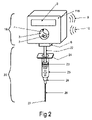
図2を参照すると、シリンジのプランジャ軸に取り付けられたシリンジ使用監視デバイスの他の実施形態が示される。取外し可能シリンジ使用監視デバイス1B部及びシリンジ20が示される。この実施形態において、取外し可能シリンジは、指挿入ゾーン2が位置するハウジング11Bを備える監視デバイス1B部を使用する。指挿入ゾーン2内に指が挿入されると、後により詳しく説明される指挿入アクション81が開始される。シリンジ充填アクション82においてシリンジに薬剤が充填されると、薬剤を投与する人間の指が上方向に力を加え、それによって、指挿入ゾーン2の上部に位置する充填適用センサ4がトリガされる。このシリンジ充填アクション82は、本明細書で説明される多数のイベントをトリガし得る。指が加力ゾーン3に下方向の力を加えると、本明細書で説明される注射アクション83がトリガされる。バレル25内に位置するプランジャ軸22及びプランジャシール23が示される。バレル25はハブ28に取り付けられ、ハブ28から針軸26が突出する。針軸26の先端に斜面27があり、これが、皮膚又は注射されるものの表面を穿刺する。バレル25の上部にトップカラー24がある。又はウジング11Bの底部に位置するプランジャ取付けゾーン6も示され、この実施形態の1つは、図3により詳しく示される。図1は、ディスプレイ8及び無線伝送信号9及び無線受信信号10も示す。図1及び図2に異なる特徴が示されるが、いずれの実施形態も、バーグラフ5、スピーカ7、ディスプレイ8、及び、例えば図2に示す無線など任意の通信方法を含むことができることが理解されよう。一般システムは、図7に模式的に示される。
Referring to FIG. 2, another embodiment of a syringe use monitoring device attached to the plunger shaft of a syringe is shown.
図3A及び図3Bを参照すると、シリンジ使用監視デバイスのプランジャ取付けゾーン6の断面の一実施形態の拡大図が示される。図3Aは、一般ハウジング11の断面を示し、プランジャトップ把持部15が一般ハウジング11の底部に取り付けられる。プランジャトップ21及びプランジャ軸22が取付け位置において示される。図3Bは、図3Aに示す図に対し直角から見た断面図である。この図において、プランジャトップ21及びプランジャ軸22は連結されていないが、取付け方向が示される。一般ハウジング11及びプランジャトップ把持部15が示される。また、シリンジ取付けセンサ16も示され、これはこの実施形態において、プランジャトップ21及びプランジャ軸22がプランジャ取付けゾーン6内に挿入されると押圧されるスイッチであってよい。
3A and 3B, an enlarged view of one embodiment of a cross-section of the
図4を参照すると、薬剤が既にシリンジ内にある、使い捨て注射用プランジャに組み込まれた本発明の実施形態が示される。一体型プランジャを有するシリンジ使用監視デバイス50及びシリンジ部51が示される。この実施形態において、一体型プランジャを有するシリンジ使用監視デバイス50部は、指挿入ゾーン2が位置するハウジング11Cを備える。指挿入ゾーン2内に指が挿入されると、後により詳しく説明される指挿入アクション91が開始される。またこれにより、一体型プランジャを有するシリンジ使用監視デバイス50がオンにされ、又はこれに電力が印加され得る。この実施形態において、シリンジは薬剤又は物質55を既に充填されているので、図1及び図2に示す実施形態と同様の充填動作は存在しない。また、個別のオンスイッチ又はボタン(不図示)があってもよく、デバイスは、使用前に包装から取り出されるとオンになってもよい。指が加力ゾーン3に下方向の力を加えると、本明細書で説明される注射アクション93がトリガされる。バレル25内に位置する一体型プランジャ軸53及びプランジャシール23が示される。バレル25はハブ28に取り付けられ、ハブ28から針軸26が突出する。針軸26の先端に斜面27があり、これが、皮膚又は注射される物の表面を穿刺する。またこれは、注射前に取り外されるキャップ54も備える。バレル25の上部にトップカラー24がある。ディスプレイ8、スピーカ7、及び無線伝送信号9及び無線受信信号10も示される。また、可視ID52も示され、これは、少なくとも1つのカラーコード領域、少なくとも1つの英数字コード及び/又は名称、QRコード、バーコード、少なくとも1つの固有識別パターン、又はそれらのいずれかの全体的又は部分的な任意の組み合わせを含むがこれらに限定されない多くの形式をとってよい。また、図1に示すようなバーグラフ5、及び例えば図4及び図2のみに示す無線など任意の通信方法もあってよい。一般システムは、図7に模式的に示される。
Referring to FIG. 4, there is shown an embodiment of the invention incorporated into a disposable injection plunger with medicament already in the syringe. Syringe
図5を参照すると、シリンジ使用監視デバイス43と、スマートデバイスディスプレイ31を有するスマートデバイス30との間の通信が示される。無線伝送信号9及び無線受信信号10が示され、これにより、これら2つのデバイス間の双方向無線通信が可能である。スマートデバイスディスプレイ31は、コスト節減特徴として、一般化シリンジ使用監視デバイス43用のディスプレイとして使用され得る。図には、一般化ハウジング11も示される。この実施形態において、スマートデバイスは、薬剤及び/又は物質のライブラリを含む。専用ソフトウェアを用いると、2つのデバイスは協働し、スマートデバイスの計算、表示、及び通信能力の全力を加えた強力なシステムとなる。
Referring to FIG. 5, communication between syringe
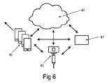
図6を参照すると、シリンジ使用監視デバイス43を組み込むシステムと、少なくとも1つのスマートデバイス40、マスタデータベースを有する中央プロセッサ41、及びクラウドコンピューティング環境42(「クラウド」)の間の通信とが示される。この実施形態において、シリンジ使用監視デバイス43は、少なくとも1つのスマートデバイス40、マスタデータベースを有する中央プロセッサ41、又はクラウド42のいずれかと直接通信することができる。少なくとも1つのスマートデバイス40は、任意の数のトポロジー構造において他の任意の数の少なくとも1つのスマートデバイス40と通信する任意の数のスマートデバイスであってよい。少なくとも1つのスマートデバイス40は、マスタデータベースを有する中央プロセッサ41、クラウド42、又は少なくとも1つの一般化シリンジ使用監視デバイス43と通信することもできる。この実施形態において、クラウド42は、少なくとも1つのスマートデバイス40、マスタデータベースを有する中央プロセッサ41、又は少なくとも1つの一般化シリンジ使用監視デバイス43と通信することができる。またこの実施形態において、マスタデータベースを有する中央プロセッサ41は、少なくとも1つのスマートデバイス40、クラウド42、及び少なくとも1つの一般化シリンジ使用監視デバイス43と通信することができる。このように、システムの任意の部分は、システムの他の任意の部分と直接通信することができ、あるいはシステム内の他の要素に連絡するためにシステム内の他の要素を介して通信することもできる。データベースは、多数のスマートデバイスに同様に、かつクラウドに分散され得る。病院又は健康管理ネットワーク全体において、これは、追跡及び投薬データベースに注射、吸入、又は摂取が可能な薬剤を組み込むための強力なツールをもたらし、投薬スケジュール及び投薬量を追跡するだけではなく誤った投薬及び投薬量といった過誤を防ぐこともできる。
Referring to FIG. 6, a system incorporating a syringe
図7を参照すると、様々な実施形態が導出され得る一般システムのブロック図が示される。本発明の主旨の範囲内に留まり実装され得る多くの実施形態が存在する。システムの中心はマイクロプロセッサ100及びサポートエレクトロニクス120であり、それら全てが一般化ハウジング11内に収容される。バッテリ101がシステムに給電し、電力は、上述したようにシリンジの挿入によって、包装から取り出すことによって、及びスイッチ又はプッシュボタン121を用いて開始され得る。バッテリ101は、一般化ハウジング及びシリンジ使用監視デバイスが多くの薬剤を投与するために繰り返し使用されることを可能にし得る、再充電可能バッテリであってよい。電力の再充電は、電気コネクタ102を介して得ることができ、電気コネクタ102は、ワイヤ110を介した通信も可能にし得る。プランジャ取付けセンサ103もまた、シリンジ使用監視デバイスへの電力の印加が可能であってよい。充填センサ104は、マイクロプロセッサ100への入力であってよい。ロードセル105、力感知レジスタ117、又は歪ゲージ118は、適切に較正された時の加力を提供するために用いられ得る。圧力は力/単位面積に等しいため、力が分かると圧力が決定され得る。通信は、無線トランシーバ119を含むいくつかの方法によって実現され得る。トランシーバ119は、一体型トランシーバであってよく、あるいは、送信機及び受信機を用いて生成されてよく、任意の構成を便宜上トランシーバ119と呼ぶものとする。通信は、赤外線(IR)信号を介して生じてもよい。IRエミッタ111は、発信IR信号112を生成してよく、IRセンサ113は、IR受信信号114を受信してよい。光ファイバ通信は、光ファイバケーブル116に接続された光ファイバコネクタ115を介して信号を受信及び/又は送信することによって実現され得る。ディスプレイは、バーグラフ106、LCDディスプレイ107、又はLEDディスプレイ108であってよい。上述したように、信号は、ディスプレイデバイスとしても使用され得るスマートデバイスへ通信され得る。音声は、発話オーディオメッセージ、オーディオアラーム、サイレン、周波数、又は任意の音声形式で、スピーカ109を介して発され得る。サポートエレクトロニクス120は、信号フィルタリング、増幅、レベルシフト、レベルオフセット、変調、及び他の機能を実行することができる。
Referring to FIG. 7, a block diagram of a general system from which various embodiments can be derived is shown. There are many embodiments that can be implemented that remain within the scope of the present invention. The heart of the system is
図8を参照すると、例えば図1及び図2に示すような取外し可能シリンジ使用監視デバイスの実施形態に関する様々な動作及びアクションを示すフローチャートが示される。シリンジ取付けアクション80は、シリンジ使用監視デバイスの起動及び/又はシリンジ使用監視デバイスへの電力印加、及び少なくとも1つの第1の指示及び/又は警告及び/又は発話メッセージの生成を開始させる。指挿入アクション81は、少なくとも1つの第2の指示及び/又は警告及び/又は発話メッセージを生成させる。シリンジ充填アクション82は、少なくとも1つの第3の指示及び/又は警告及び/又は発話メッセージを生成させる。注射アクション83は、少なくとも1つの第4の指示及び/又は警告及び/又は発話メッセージを生成させる。この第4の指示及び/又は警告は、少なくとも1つの緊急警告、アラーム、注射が許容限度内で生じていることを示す少なくとも1つの音声及び/又は可聴周波数、上記加力ゾーン内に付与された力に比例する少なくとも1つの音声及び/又は可聴周波数の少なくとも1つであってよい。アップロードデータ84は、実施形態に依存する任意選択的な機能であってよいが、少なくとも1つのスマートデバイス、マスタデータベースを有する中央プロセッサ、少なくとも1つのクラウド、又は少なくとも1つの他のシリンジ使用監視デバイスへの少なくとも1つの通信であってよい。
Referring to FIG. 8, a flowchart illustrating various operations and actions associated with an embodiment of a removable syringe usage monitoring device such as that shown in FIGS. 1 and 2 is shown. The attach
図9を参照すると、例えば図4に示すような、一体型プランジャを有するシリンジ使用監視デバイスの実施形態に関する様々な動作及びアクションを示すフローチャートが示される。指挿入アクション91は、少なくとも1つの第1の指示及び/又は警告及び/又は発話メッセージを生成させる。注射アクション93は、少なくとも1つの第2の指示及び/又は警告及び/又は発話メッセージを生成させる。この第2の指示及び/又は警告は、少なくとも1つの緊急警告、アラーム、注射が許容限度内で生じていることを示す少なくとも1つの音声及び/又は可聴周波数、上記加力ゾーン内に加わった力に比例する少なくとも1つの音声及び/又は可聴周波数の少なくとも1つであってよい。アップロードデータ94は、実施形態に依存する任意選択的な機能であってよいが、少なくとも1つのスマートデバイス、マスタデータベースを有する中央プロセッサ、少なくとも1つのクラウド、又は少なくとも1つの他のシリンジ使用監視デバイスへの少なくとも1つの通信であってよい。
Referring to FIG. 9, a flowchart illustrating various operations and actions for an embodiment of a syringe use monitoring device having an integral plunger, such as that shown in FIG. 4, is shown.
図10を参照すると、シリンジのプランジャ軸に取り付けられたシリンジ使用監視デバイスの実施形態が示される。このU形ハウジング11Dには、図1の円形指挿入ゾーン2とは異なり、U字形開口チャネルU形指挿入ゾーン132がある。取外し可能シリンジ使用監視デバイス1C部及びシリンジ20が示される。この実施形態において、取外し可能シリンジ使用監視デバイス1C部は、U形指挿入ゾーン132が位置するU形ハウジング11Dを備える。U形指挿入ゾーン132内に指が挿入され、又は1又は複数の指が底部充填適用センサ4A及び/又は底部充填適用センサ4Bに上方向の力を加えると、既に上述した指挿入アクション81が開始される。シリンジ充填アクション82においてシリンジ20に薬剤が充填されると、薬剤を投与する人間の1又は複数の指が上方向に力を加え、それによって、U形ハウジング11Dの底部に位置する底部充填適用センサ4A及び/又は底部充填適用センサ4Bがトリガされる。シリンジ充填アクション82は、本明細書で説明される多数のイベントをトリガすることができる。シリンジ充填アクション82の後、指が加力ゾーン3に下方向の力を加えると、既に上述した注射アクション83がトリガされる。開口チャネル及びU字形以外に、この実施形態と図1の実施形態との唯一の相違は、ここでシリンジ充填アクション82が底部充填適用センサ4A及び/又は底部充填適用センサ4Bによって感知されることである。バレル25内に位置するプランジャ軸22及びプランジャシール23も示される。バレル25はハブ28に取り付けられ、ハブ28から針軸26が突出する。針軸26の先端に斜面27があり、これが、皮膚又は注射されるものの表面を穿刺する。バレル25の上部にトップカラー24がある。また、U形ハウジング11Dの底部に位置するプランジャ取付けゾーン6も示され、この実施形態の1つは図3に示される。図1は、バーグラフ5及びスピーカ7も示す。
Referring to FIG. 10, an embodiment of a syringe use monitoring device attached to the plunger shaft of a syringe is shown. This
このU形ハウジング11D構成は、薬剤が既にシリンジ内にある、使い捨て注射用プランジャに組み込まれた本発明の実施形態を示す図4の実施形態と組み合わせることができる。この実施形態において、シリンジ部51は既に充填されているので、底部充填適用センサ4A又は底部充填適用センサ4Bは存在しない。U形指挿入ゾーン132内に指が挿入されると、本明細書で既に説明したように指挿入アクション91が開始される。またこれは、シリンジ使用監視デバイスをオンにし、又はシリンジ使用監視デバイスに電力を印加させてもよい。この実施形態において、シリンジは既に薬剤又は物質55を充填されているので、図1、図2、及び図10に示す実施形態のような充填動作は存在しない。また、個別のオンスイッチ又はボタン(不図示)があってもよく、デバイスは、使用前に包装から取り出されるとオンになってもよい。指が加力ゾーン3に下方向の力を加えると、本明細書で説明される注射アクション93がトリガされる。図4において既に説明したように、バレル25内に位置する一体型プランジャ軸53よびプランジャシール23がある。バレル25はハブ28に取り付けられ、ハブ28から針軸26が突出する。針軸26の先端に斜面27があり、これが、皮膚又は注射されるものの表面を穿刺する。これは、注射前に取り外されるキャップ54も備える。バレル25の上部にトップカラー24がある。ディスプレイ8、スピーカ7、及び無線伝送信号9及び無線受信信号10も示される。また、可視ID52も示され、これは、少なくとも1つのカラーコード領域、少なくとも1つの英数字コード及び/又は名称、QRコード、バーコード、少なくとも1つの固有識別パターン、又は図面のいずれかにおいて上述したもののいずれかの全体的又は部分的な任意の組み合わせを含むがこれらに限定されない多くの形式をとってよい。また、図1に示すようなバーグラフ5、及び例えば図4及び図2のみに示す無線など任意の通信方法もあってよい。システムの実施形態は図7において模式的に示され、多数の組み合わせが、本発明の主旨の範囲内に留まり実装され得る。
This
ここで、本明細書で論述され、又は本開示から想起される様々な実施形態を構成する際に用いられ得るサブシステムを参照すると、ロードセルは様々な形式をとり、実施形態において、既製品であってよく、又はカスタム設計され力感知サブシステムに統合されてもよい。これらは、Phidgets社(商標)製の100グラムマイクロロードセルRB‐Phi‐203に類似してよく、3~10ボルトの給電時に100uv/ボルトの速度であり、一般に、例えばPhidgets社のPhi‐107又は演算増幅器を利用する他のカスタム設計増幅器などのホイートストンブリッジ増幅器とともに用いられる。他のロードセルは、780グラムRB‐Phi‐117であってよい。これらのロードセルは一般に、高い再現性、精度、及び精密度を有する。例えばRB‐Phi‐117は、フルスケールの0.05%の精密度、フルスケールの0.05%の非線形性、フルスケールの0.05%の再現性、及び30分間にわたりフルスケールの0.1%のクリープを有する。
Referring now to subsystems that may be used in constructing various embodiments discussed herein or conjured from this disclosure, load cells take various forms and, in embodiments, are off-the-shelf or it may be custom designed and integrated into the force sensing subsystem. These may be similar to the
S410及びS415は、Strain Measurement Devices(商標)社が製造する、小型かつ薄型ボタンロードセルである。これらは、0.24、0.5、及び1KGの力感知範囲に入る。これらは、4本のワイヤによって4つの抵抗素子ブリッジ構成に繋げられ、各ワイヤは、ブリッジの隣接する2つの抵抗素子の交点である。 S410 and S415 are small, low profile button load cells manufactured by Strain Measurement Devices™. These fall within the force sensing ranges of 0.24, 0.5, and 1 KG. These are joined by four wires into a four resistive element bridge configuration, each wire being the intersection of two adjacent resistive elements in the bridge.
S251及びS252は、0.4~22ポンド範囲における最大力を測定する小型プラットフォーム薄型ロードセルである。これらは、3000オームの薄膜ブリッジ構成であり、例えば本発明のような医療用途のために理想的である。S215モデルは、低電力消費及び高精度のために10,000オームのブリッジを特徴とする超薄型小型単一ポイントロードセルである。 S251 and S252 are small platform low profile load cells that measure maximum force in the 0.4-22 lb range. These are 3000 ohm thin film bridge configurations and are ideal for medical applications such as the present invention. The S215 model is an ultra-thin miniature single point load cell featuring a 10,000 ohm bridge for low power consumption and high accuracy.
例えば電圧は、4つのワイヤブリッジのうち2本のワイヤにわたって印加されてよく、他の2本のワイヤ又はノードから差動電圧が得られる。この差動電圧はその後、一般に、考えられる多数の集積回路のうちの1つとして一般的に入手可能な計器増幅器を用いて増幅される。例えば、考えられる2つのIC増幅器は、最高でLM308精度の演算増幅器から、最低でLM324クワッドオペアンプまで、又はそれらの間のいずれかに基づいてよい。何百ものオペアンプは、例えばほんの数例を挙げると、Texas Instruments(商標)社、National Semiconductor(商標)社、Fairchild(商標)社、及びAnalog Devices(商標)社などの製造会社から選択され得る。力に比例する増幅、オフセット、及びバッファ後の電圧は、その後、後続する定量化及び処理のために、スタンドアロン部品であってよく、又はマイクロプロセッサパッケージに統合され得るA/Dコンバータへ供給され得る。例えば、Microchip社の多くのプロセッサは、本発明に必要な制御機能の全てを実行するために十分な処理電力と関連してアナログ入力に適応し得る。A/D分解能は、今やローエンドプロセッサにおけるものとなった8~16ビットで変化し、Microchip(商標)社のATSAM4E8C及びIC24FJ128GC010プロセッサのように16~32ビットの分解能を有することは珍しくない。 For example, a voltage may be applied across two wires of a four wire bridge and a differential voltage obtained from the other two wires or nodes. This differential voltage is then typically amplified using an instrumentation amplifier, commonly available as one of many possible integrated circuits. For example, two possible IC amplifiers may be based on LM308 precision operational amplifiers at best, down to LM324 quad op amps, or anything in between. Hundreds of op amps can be selected, for example, from manufacturers such as Texas Instruments™, National Semiconductor™, Fairchild™, and Analog Devices™, just to name a few. The force-proportional amplified, offset, and buffered voltages can then be fed to an A/D converter, which can be a stand-alone component or integrated into a microprocessor package, for subsequent quantification and processing. . For example, many Microchip processors can accommodate analog inputs in conjunction with sufficient processing power to perform all of the control functions required by the present invention. A/D resolution varies from 8 to 16 bits, which is now in low-end processors, and it is not uncommon to have 16 to 32 bits of resolution, such as Microchip's ATSAM4E8C and IC24FJ128GC010 processors.
またロードセルは、荷重の関数として抵抗を変化させる歪ゲージワイヤで構成されてもよい。これらのワイヤは一般に、互いに対して動く2つの表面の間に取り付けられ、ワイヤに加力することによってワイヤを引き伸ばす変位をもたらす。ワイヤが線形領域の変形の範囲内にある限り、抵抗は変形の関数として変化し、再現可能な結果をもたらす。 The load cell may also consist of a strain gauge wire that changes resistance as a function of load. These wires are generally mounted between two surfaces that move relative to each other, and exerting a force on the wire produces a displacement that stretches the wire. As long as the wire is within the linear region of deformation, the resistance will vary as a function of deformation, yielding reproducible results.
ピエゾロードセル又は歪ゲージセンサは、例えばPCB Piezotronics MTSシステム社の740B02型センサなど高価なものから、非常に安価なものまでに及んでよい。これらは、低費用で製造され、個々に較正され、十分正確に動作し得る。非常に単純な実装形態において、Velleman社が製造するような音響インジケータは、指が力を付与し得る点とプレートとの間に挟まれ得る。ピエゾ出力は、荷重付与の変化率の関数として電圧を生成するので、付与される力の測定値及びこれが関連する圧力を生成するためにこの信号を積分することが賢明である。この積分は、低ドリフト演算増幅器を利用する何百もの構成のいずれか1つによって実行されるアナログ積分の形式であってよく、あるいは積分は、増幅及びバッファリングの後にピエゾ出力信号をデジタルサンプリングすることによって実行され得る。 Piezo load cells or strain gauge sensors can range from expensive, for example PCB Piezotronics MTS Systems Inc. 740B02 type sensors, to very inexpensive. They can be manufactured at low cost, individually calibrated and operate sufficiently accurately. In a very simple implementation, an acoustic indicator such as manufactured by Velleman can be sandwiched between a plate and a point where a finger can apply force. Since the piezo output produces a voltage as a function of the rate of change of load application, it is prudent to integrate this signal to produce a measure of the applied force and its related pressure. This integration may be in the form of analog integration performed by any one of hundreds of configurations that utilize low-drift operational amplifiers, or the integration digitally samples the piezo output signal after amplification and buffering. can be performed by
例えばOmega社のSGT‐1000‐TYシリーズ及びSGK‐Lシリーズの歪ゲージなど、成分線形歪ゲージも利用可能である。抵抗及び対応する抵抗変化は、電流及び電圧を測定することによって、又は電圧制御発振器における周波数及び対応する周波数変化を測定することによって計算され得る。SGT‐2DDシリーズは、4つのシェアゲージ及び単一のキャリアプレートから成る。2つのハーフブリッジが、1つのホイートストンブリッジ全体を形成するために用いられ得る。上記の方法は全て、アナログ回路設計の技術者によって容易に実行され得る。 Component linear strain gauges are also available, for example Omega's SGT-1000-TY series and SGK-L series strain gauges. Resistance and corresponding resistance change can be calculated by measuring current and voltage, or by measuring frequency and corresponding frequency change in a voltage controlled oscillator. The SGT-2DD series consists of four shear gauges and a single carrier plate. Two half-bridges can be used to form an entire Wheatstone bridge. All of the above methods can be easily implemented by analog circuit design engineers.
例えばPoluluモデル1696などの力感知レジスタFSRは一般的に入手可能であり、付与される力の関数として抵抗を変化させる。これらは、既製品であってよく、又は印刷又はシルクスクリーニングの結果として製造されてよい。抵抗が測定及びFSR較正され、結果として生じる力をもたらし得る。これらは、歪ゲージよりも精度が低い傾向があるが、適切な較正によって精度及び再現性を実現することができ、本発明の主旨から逸脱するものではない。 Force sensing resistors FSR, such as the Polulu model 1696, are commonly available and vary resistance as a function of applied force. These may be off-the-shelf or manufactured as a result of printing or silk screening. The resistance can be measured and FSR calibrated to give the resulting force. These tend to be less accurate than strain gauges, but with proper calibration accuracy and repeatability can be achieved without departing from the spirit of the invention.
実施形態において使用するためのBluetoothトランシーバはどこにでもあり、多くの製造元から一般的に入手可能である。伝送距離は、特徴として様々である。いくつかの市販される既製品であるBluetoothトランシーバは、
1a)Grid Connect(商標)社から入手可能なBT832F拡張範囲Bluetooth低エネルギ(BLE)5モジュール、
2a)Grid Connect(商標)社から入手可能なBT832X拡張範囲Bluetooth低エネルギ(BLE)5モジュール、
3a)Grid Connect(商標)社のBluetoothシリアルアダプタFirefly DTE NOPS、
4a)Medshop(商標)社のPhillips FR3 Bluetoothトランシーバモジュール
である。
Bluetooth transceivers for use in embodiments are ubiquitous and commonly available from many manufacturers. Transmission distances are characteristically different. Some commercially available off-the-shelf Bluetooth transceivers are
1a) BT832F extended range Bluetooth Low Energy (BLE) 5 module available from Grid Connect™, Inc.;
2a) BT832X extended range Bluetooth Low Energy (BLE) 5 module available from Grid Connect™, Inc.;
3a) Grid Connect™ Bluetooth serial adapter Firefly DTE NOPS,
4a) Phillips FR3 Bluetooth transceiver module from Medshop™.
回路内にサブシステムとして組み込まれ得る他のモジュール又はチップセットは、ほんの数例を挙げると、
1b)Hobbytronics(商標)社から入手可能なワイヤレスBluetoothV2.0 RS232 TTLトランシーバモジュール、
2b)Lanka Tronics(商標)社によって製造され、Astral Robot社から入手可能なワイヤレスシリアル4ピンBluetooth RFトランシーバモジュールHC‐06 RS‐232、
3b)Lanka Tronics(商標)社によって製造される、約30フィートの範囲を有する、ワイヤレスBluetooth RFトランシーバモジュールHC‐05、
4b)FastTeck(商標)社のLB3431ワイヤレスBluetoothシリアルトランシーバモジュール
である。
Other modules or chipsets that may be incorporated as subsystems within the circuit are, to name but a few:
1b) Wireless Bluetooth V2.0 RS232 TTL transceiver module available from Hobbytronics(TM),
2b) Wireless Serial 4-Pin Bluetooth RF Transceiver Module HC-06 RS-232 manufactured by Lanka Tronics™ and available from Astral Robot,
3b) Wireless Bluetooth RF transceiver module HC-05, manufactured by Lanka Tronics™, with a range of approximately 30 feet;
4b) FastTeck™ LB3431 Wireless Bluetooth Serial Transceiver Module.
これらへの接続は同様であり、多くは、システムへの最低4つのワイヤ取付けを必要とする。一般的に、(3.3ボルト、5ボルト、又は他の電圧であり得る)モジュールに給電するための基線及びVcc+線、(多くの場合Rxピンと称される)信号を受信するためのピン、及び(多くの場合Txピンと称される)信号を送信するためのピンが存在する。利用可能なトランシーバは多数存在する。電力を節減するために、電力制御システムがシステムに組み込まれ得るので、電力は、通信が必要な場合のみトランシーバに印加される。いくつかのトランシーバは、トランシーバを低電力又はスリープモードから起動するためのイネーブル線を組み込む。 Connections to these are similar and many require a minimum of four wire attachments to the system. Generally, the baseline and Vcc+ lines for powering the module (which can be 3.3 volts, 5 volts, or other voltage), a pin for receiving the signal (often referred to as the Rx pin), and a pin for sending signals (often referred to as the Tx pin). There are many transceivers available. To save power, a power control system can be incorporated into the system so that power is applied to the transceiver only when communication is required. Some transceivers incorporate an enable line to wake the transceiver from low power or sleep mode.
本発明の実施形態において、RFIDチップが用いられる。RFIDチップ及びサブシステムは市販されており、店舗における製品識別及び倉庫における在庫管理から、家畜、ペット、人間、ファイル、及び識別を必要とする他の事物の監視まで、あらゆることに用いられる。タグは、バッテリの形式で電力を所有する能動タグ、及びタグの外部で生成された電磁界から電力を受け取る無給電の受動タグという2つの種類に分類される。受動タグは、電磁放射を受け取り、この受信エネルギを、タグ内に組み込まれたチップが、第1の場所におけるタグを励起するために電力を受け取った受信アンテナを介して符号化信号を送り返すことを可能にする形式に変換する。この符号化ID信号は、例えば薬剤又は化学物質含有量、推奨投薬量、使用期限、製造日、製造元、生産ロット、禁忌、及び/又は他の任意の情報を含むがこれらに限定されない、任意の量の情報を包含する、ほぼ任意の長さであってよい。この情報は、送信デバイスによって受信されてよく、RFIDタグが配置された容器の内容物に関する情報が取得され得る。典型的なシナリオは、薬剤がシリンジに充填される予定であるといったものである。RFIDタグは刺激され、内容物データをシリンジへ送信する。シリンジはこの情報を受信し、内容物及び/又は他の有用な情報に関してユーザに通知する。ユーザは、注射のための準備として、シリンジに薬剤を充填する。ユーザは薬剤を注射し、注射は、デバイスによってユーザに提供された情報に基づいて、本明細書において予め定義された適切なパラメータに従って行う。 In embodiments of the present invention, RFID chips are used. RFID chips and subsystems are commercially available and are used for everything from product identification in stores and inventory control in warehouses, to monitoring livestock, pets, people, files, and other things that require identification. Tags fall into two classes: active tags, which possess power in the form of batteries, and unpowered passive tags, which receive power from electromagnetic fields generated outside the tag. A passive tag receives electromagnetic radiation and converts this received energy into an encoded signal that a chip embedded within the tag transmits back through a receiving antenna that receives power to excite the tag at a first location. Convert to a format that allows This encoded ID signal may include, for example, but not limited to, drug or chemical content, recommended dosage, expiration date, date of manufacture, manufacturer, production lot, contraindications, and/or any other information. It can be of almost any length, containing any amount of information. This information may be received by the transmitting device and information regarding the contents of the container in which the RFID tag is placed may be obtained. A typical scenario is that a drug is to be filled into a syringe. The RFID tag is stimulated and transmits content data to the syringe. The syringe receives this information and notifies the user as to the contents and/or other useful information. The user fills the syringe with medication in preparation for injection. The user injects the medicament and the injection takes place according to the appropriate parameters predefined herein based on the information provided to the user by the device.
典型的なRFIDサブシステムは、Allen Bradley(商標)社モデルの56RF‐UB‐IPである。考えられる他のRFIDサブシステムは、Radiometrix(商標)社のFPX3‐869‐20である。本発明に組み込まれ、本発明の主旨の範囲内に留まり得る多数のサブシステムが存在する。 A typical RFID subsystem is the Allen Bradley™ Model 56RF-UB-IP. Another possible RFID subsystem is the Radiometrix™ FPX3-869-20. There are numerous subsystems that can be incorporated into the present invention and remain within the scope of the present invention.
本発明のデバイス間の通信において、少なくとも1つの送信者と少なくとも1つの受信者との間のデータ及び/又は信号の送信、データ及び/又は信号の受信、又はデータ及び/又は信号の送受信が生じる。本発明の目的を実現するために任意の形式の通信が用いられ得る。任意のモードの通信は、データの暗号化及び復号を取り入れてよい。 Communication between the devices of the present invention involves transmitting data and/or signals, receiving data and/or signals, or transmitting and receiving data and/or signals between at least one sender and at least one receiver. . Any form of communication may be used to achieve the objectives of the present invention. Any mode of communication may incorporate encryption and decryption of data.
例えば、通信は、アナログ信号、デジタル信号、又は両方の送信であってよい。通信は、例えばあるマイクロプロセッサ又はデジタル要素又はシステムが、いずれかの方向の別のマイクロプロセッサ又はデジタル要素又はシステムへデータを送信する時に一般的に生じるような、1つのデジタルデバイス出力から1つのデジタルデバイス入力のように、ワイヤを介して生じ得る。ワイヤは、任意の構成要素を他の任意の構成要素に直接接続する任意の導電トレースと考えられ得る。データは、より長い距離にわたり、又は多くのデバイスへ送信されるようにバッファされてもよい。データは、直列、並列、又は両方であってよい。通信は、光ファイバ伝送路を介してデータ又は信号を送信する場合、光であってよい。光通信は、例えばIR、可視、又はUVなど任意の周波数の光を受け取る光センサによって受け取られ得る任意の周波数の光を生成する任意の光送信機の使用を伴ってよい。 For example, communication may be the transmission of analog signals, digital signals, or both. Communication is from one digital device output to one digital device output, such as typically occurs when one microprocessor or digital element or system transmits data in either direction to another microprocessor or digital element or system. Like device inputs can occur over wires. A wire can be considered any conductive trace that directly connects any component to any other component. Data may be buffered to be sent over longer distances or to many devices. Data may be serial, parallel, or both. Communication may be optical when transmitting data or signals over fiber optic transmission lines. Optical communication may involve the use of any optical transmitter that produces light of any frequency that can be received by an optical sensor that receives light of any frequency, such as IR, visible, or UV.
例えば、現在多くのマイクロプロセッサは、A/D(アナログ-デジタル)コンバータ、D/A(デジタル-アナログ)コンバータ、又は両方を組み込む。外付けA/Dコンバータはアナログ信号を受け取ってもよく、アナログ信号はマイクロプロセッサへ供給されてよく、D/Aコンバータは、デジタル数字又はデジタル数字のストリームからアナログ信号を生成するためにマイクロプロセッサから供給され得る。アナログ通信の例は、アナログ信号を生成するセンサであってよく、信号は回路によって増幅及び/又はスケーリング及び/又はオフセットされ、その後この信号は、通信回線を介してマイクロプロセッサ又は他の構成要素又は複数の構成要素におけるアナログ入力へ送信され、続いてここで、更なる処理のためにデジタル数字に定量化される。 For example, many microprocessors today incorporate A/D (analog-to-digital) converters, D/A (digital-to-analog) converters, or both. An external A/D converter may receive an analog signal, which may be supplied to the microprocessor, and a D/A converter from the microprocessor to generate analog signals from digital numbers or streams of digital numbers. can be supplied. An example of analog communication may be a sensor that produces an analog signal, which is amplified and/or scaled and/or offset by circuitry, after which this signal is sent over a communication line to a microprocessor or other component or It is sent to analog inputs in multiple components, where it is subsequently quantified to digital numbers for further processing.
他の形式の無線通信は、RFID、近距離NFCデバイス、無給電NFCチップタグ、2400~2480mhz帯域内のBluetooth、現在既知又は未知の帯域内のBluetooth、周波数ホッピングスペクトラム拡散ベースシステム、WI-FI、Zigbee IEEE802.15規格、欧州において686MHZ及び/又は米国において915MHZ及び/又はほぼ全世界の管轄において2.4GHZを用いる工業、科学、及び医療利用のための通信の少なくとも1つを利用してよい。 Other forms of wireless communication are RFID, near field NFC devices, passive NFC chip tags, Bluetooth within the 2400-2480 mhz band, Bluetooth within currently known or unknown bands, frequency hopping spread spectrum based systems, WI-FI, Zigbee At least one of communications for industrial, scientific, and medical applications using the IEEE 802.15 standard, 686 MHZ in Europe and/or 915 MHZ in the United States and/or 2.4 GHZ in most worldwide jurisdictions may be utilized.
通信は、空間内のある場所から音響波を発し、空間内の別の場所において音響エネルギを受け取ることによって、聴覚的に生じてもよい。 Communication may occur audibly by emitting acoustic waves from one location in space and receiving acoustic energy at another location in space.
典型的な通信サブシステムは、通信をもたらすために必要な構成要素を組み込むサブシステムであってよく、例えば有線、無線、光、音響、又は空間内の少なくとも1つの場所から空間内の少なくとも1つの他の場所へ情報を送信することができる他の任意の手段を介して任意のモードで通信を可能にする任意のデバイスであってよい。例えば、データの受信及び/又はデータの送信が想定される。 A typical communication subsystem may be a subsystem that incorporates the necessary components to provide communication, such as wired, wireless, optical, acoustic, or communication from at least one location in space to at least one location in space. It may be any device that enables communication in any mode via any other means capable of transmitting information to other locations. For example, data reception and/or data transmission is envisioned.
典型的なスマートデバイスはモバイルデバイスであってよく、これは、人間がデータ及び情報にアクセスすることを可能にする様々なポータブルデバイスを指すために用いられる総称である。モバイルデバイス(ハンドヘルドコンピューティングデバイス、ハンドヘルドデバイス、ハンドヘルドコンピュータ、又は単にハンドヘルドとしても知られる)は、ハンドヘルドコンピューティングデバイスであってもよく、これは、タッチ入力及び/又は小型キーボードを有することもできるディスプレイスクリーンを有してよい。 A typical smart device may be a mobile device, a generic term used to refer to various portable devices that allow humans to access data and information. A mobile device (also known as a handheld computing device, handheld device, handheld computer, or simply handheld) may be a handheld computing device, which may also have touch input and/or a miniature keyboard display May have a screen.
スマートデバイスは、ハンドヘルドコンピューティングデバイスであってよく、オペレーティングシステム(OS)を有してよく、様々な種類のアプリケーションソフトウェア、いわゆるアプリを実行してよい。多くのハンドヘルドデバイスは、インターネット、他のコンピューティングネットワーク、及び/又は例えば自動車又はマイクロフォンヘッドセットなど他のBluetooth対応デバイスへの接続を可能にするWI‐FI、Bluetooth、及びGPS機能の少なくとも1つも備えてよい。またスマートデバイスは、WI‐FI、無線波及び/又は電磁放射、及び/又はBluetoothの少なくとも1つを利用する少なくとも1つの通信受信機デバイス及び/又は少なくとも1つの通信送信機デバイス及び/又は少なくとも1つの通信送信機/受信機デバイスを組み込んでよい。ビデオ又は音楽ファイル用のカメラ及び/又はメディアプレーヤ特徴もまた、バッテリ電源とともにこれらのデバイスに存在してよい。他の種類のモバイルデバイスは、タブレットコンピュータを含む。パーソナルデジタルアシスタント(「PDA」)と同様、入力及び出力は多くの場合、タッチスクリーンインタフェース、スマートフォン、PDA、エンタプライズデジタルアシスタントに結合され、これらのいずれか又は全てが、例えばバーコード読取り機能、RFID、光学式、QRコードと関連する光学式、光学式文字認識、スマートカードリーダ、及び/又は少なくとも1つのタッチコードリーダなどの統合データ捕捉デバイスを提供してよい。 A smart device may be a handheld computing device, may have an operating system (OS), and may run various types of application software, so-called apps. Many handheld devices also include at least one of WI-FI, Bluetooth, and GPS capabilities to enable connectivity to the Internet, other computing networks, and/or other Bluetooth-enabled devices, such as automobiles or microphone headsets. you can The smart device also includes at least one communication receiver device and/or at least one communication transmitter device and/or at least one communication transmitter device utilizing at least one of WI-FI, radio waves and/or electromagnetic radiation, and/or Bluetooth. may incorporate one communications transmitter/receiver device. Camera and/or media player features for video or music files may also be present in these devices along with battery power. Other types of mobile devices include tablet computers. Similar to personal digital assistants (“PDAs”), inputs and outputs are often coupled to touch screen interfaces, smart phones, PDAs, enterprise digital assistants, any or all of which may include, for example, barcode reading capabilities, RFID , optical, optical in conjunction with QR codes, optical character recognition, smart card readers, and/or at least one touch code reader may be provided.
スマートデバイスは、2以上のスマートデバイスであってよい。上述したようなモバイルデバイスは、ラップトップ、タブレット、スマートウォッチ、メインフレームコンピュータ、デスクトップコンピュータ、サーバ、及び/又はスーパーコンピュータであってよく、少なくとも1つのカメラ、リーダデバイス、入力デバイス及び/又はスキャナ、投影デバイス及び/又はシステムを含み、又はこれらに接続され得る。ユーザスマートデバイスは、インターネット又は他のネットワーク接続能力を有し、上記ネットワークにアクセスするための少なくとも1つの常駐するウェブブラウザ又は同様のソフトウェアを利用し、又は有してよい。 A smart device may be two or more smart devices. Mobile devices as described above may be laptops, tablets, smartwatches, mainframe computers, desktop computers, servers and/or supercomputers, and include at least one camera, reader device, input device and/or scanner, It may include or be connected to a projection device and/or system. A user smart device has Internet or other network connectivity capabilities and may utilize or have at least one resident web browser or similar software for accessing said network.
スマートデバイスは、例えばスマートフォン、Ipad、Iphone、Android、タブレット、車内タッチスクリーン、任意のデバイス上のタッチ感知式スクリーン、及び/又はカスタム静電容量式及び/又はタッチ感知式スクリーンを含むがこれらに限定されない、静電容量式タッチスクリーンを有する任意のデバイスであってよい。スマートデバイス及びタッチスクリーンは、スマートフォン、Iphone、Ipad、Android、コンピュータ、タブレット、リーダ、自販機を含むがこれらに限定されないものに存在するような、タッチコード及び/又は人間のタッチ及び/又は容量素子及び/又は導電素子によってアクティブ化され得る。またスマートデバイスは、wifiを介した通信及び/又は電磁的通信、写真及び/又はビデオの撮影、画像の表示、データの入力及び表示、近距離通信、Bluetooth通信のいずれかが可能であるが、これらに限定されない。 Smart devices include, for example, smart phones, Ipads, iPhones, Androids, tablets, in-vehicle touchscreens, touch-sensitive screens on any device, and/or custom capacitive and/or touch-sensitive screens. It may be any device with a capacitive touch screen that is not Smart devices and touch screens include touch cords and/or human touch and/or capacitive elements and /or may be activated by a conductive element. In addition, smart devices are capable of communication via wifi and/or electromagnetic communication, photography and/or video photography, image display, data input and display, short-range communication, and Bluetooth communication. It is not limited to these.
スマートデバイスは更に、Wi‐Fi、無線波及び/又は電磁放射、及び/又はBluetoothの少なくとも1つを利用する少なくとも1つの通信受信機デバイス及び/又は少なくとも1つの通信送信機デバイス及び/又は少なくとも1つの通信送信機/受信機デバイスの少なくとも1つであってよく、又はこれらで構成され得る。 The smart device further includes at least one communication receiver device and/or at least one communication transmitter device and/or at least one communication transmitter device utilizing at least one of Wi-Fi, radio waves and/or electromagnetic radiation, and/or Bluetooth. may be or consist of at least one of the two communication transmitter/receiver devices.
任意の数のスマートデバイスがチェーン又はネットワーク内に存在してよく、1又は複数の方向に情報を流すための直列及び並列経路を形成しており、スマートデバイスは全て、個々に及び集合的に「スマートデバイス」と称される。スマートデバイスは、インターネットへ直接、インターネットへ通信する少なくとも1つの他のスマートデバイスへ、及び/又は、少なくとも1つの他の宛先において用いられるデータのソース及び/又は更新される少なくとも1つのデータベースを処理する少なくとも1つのマスタスマートデバイスへ直接又は少なくとも1つの他のスマートデバイスを介して通信することができる。 Any number of smart devices may exist in a chain or network, forming serial and parallel paths for information to flow in one or more directions, all smart devices individually and collectively " called a smart device. A smart device processes at least one database that is sourced and/or updated for data used directly to the Internet, to at least one other smart device that communicates to the Internet, and/or at least one other destination. It can communicate directly to at least one master smart device or through at least one other smart device.
スマートデバイスは、特定の順序ではなく列挙される次の構成要素、少なくとも1つのコアを処理する少なくとも1つのマイクロプロセッサ、少なくとも1つのメモリ、少なくとも1つのディスプレイ、少なくとも1つのデータ入力手段であって、少なくとも1つのカメラ、タッチスクリーン、キーボード、少なくとも1つの形式の無線通信、少なくとも1つの光ファイバケーブルを介した少なくとも1つの形式の通信、少なくとも1つの電気接点を有する少なくとも1つの機械コネクタに接続された少なくとも1つのワイヤを介した少なくとも1つの形式の通信のうちの少なくとも1つであるデータ入力手段、少なくとも1つの他のスマートデバイス及び/又はサーバ及び/又はインターネットに接続することができるネットワークと通信するように構成された少なくとも1つのトランシーバを全体的又は部分的に備え、上記構成要素は、少なくとも1つの物理的位置に常駐する少なくとも1つのデータベース及び/又はマスタデータベースへ少なくとも1つのフォーマット化リストを送信すること、少なくとも1つの電子メール及び/又はデータを受信すること、少なくとも1つのレポートを生成することを行うようにプログラムされる。システムの動作、アクション、及び機能を制御するために必要なソフトウェアは、特定の実施形態において選択されたスマートデバイス及びネットワークによって規定される、例えばJava、C、C++、Pythonなどの適用可能なプログラミング言語において符号化され得る。 A smart device comprises the following components, listed in no particular order: at least one microprocessor processing at least one core; at least one memory; at least one display; at least one data input means; at least one camera, touch screen, keyboard, at least one form of wireless communication, at least one form of communication via at least one fiber optic cable, connected to at least one mechanical connector having at least one electrical contact Data input means being at least one of at least one form of communication via at least one wire, communicating with at least one other smart device and/or a server and/or a network capable of connecting to the Internet at least one transceiver configured in whole or in part to transmit at least one formatted list to at least one database residing in at least one physical location and/or a master database receiving at least one email and/or data; and generating at least one report. The software required to control the operation, actions, and functions of the system is dictated by the smart device and network selected in the particular embodiment, and applicable programming languages such as Java, C, C++, Python, etc. can be encoded in
タッチコードは、起こり得る多数のステータスの1つを生成するために独自に復号され得る特定の形状及び/又はパターンの導電領域である。タッチコードは、様々なサイズの一連の棒、様々なサイズの円及び互いの角度関係、長方形、及び/又は多様なステータスの1つに定量化及び復号され得る幾何学形状の少なくとも1つであってよい。導電領域及び/又は複数の領域は、導電性インクの印刷に限定されず、少なくとも1つのスマートデバイスのタッチスクリーンに接触する人間又はエンティティの静電容量効果を拡大し得る任意の導電性材料であってよい。 A touch code is a conductive area of a specific shape and/or pattern that can be uniquely decoded to produce one of many possible statuses. The touch code is at least one of a series of bars of various sizes, circles of various sizes and their angular relationship to each other, rectangles, and/or geometric shapes that can be quantified and decoded into one of various states. you can The conductive region and/or plurality of regions are not limited to printing conductive ink, but any conductive material that can magnify the capacitive effect of a person or entity contacting the touchscreen of at least one smart device. you can
エレクトロニクスは、受動素子、能動素子、アナログエレクトロニクス、デジタルエレクトロニクス、ハイブリッドエレクトロニクス、電圧調整器、集積回路、任意の種類のセンサ、発光素子、及びそれらの間の相互接続であってよい。エレクトロニクスは、バイアス、電流制限、少なくとも1つの電圧を少なくとも1つの他の電圧から生成すること、電圧増幅及び/又は電流増幅であり得る信号利得、信号スケーリング、信号オフセット、信号フィルタリング、タイミング、及び生成を含むがこれらに限定されない任意の電子システム機能を実行するために用いられ得る。電子サブシステムは、受信機、送信機、変調器、復調器、電圧調整器、信号プロセッサ、信号取得、信号定量化、信号デジタル化、アナログ信号生成、表示情報、音声発生器、1つの形式から別の形式へのエネルギの変換、データの取得、データの処理、データの格納といった機能のうちの少なくとも1つであってよく、又は少なくとも1つを実行してよい。 The electronics can be passive devices, active devices, analog electronics, digital electronics, hybrid electronics, voltage regulators, integrated circuits, sensors of any kind, light emitting devices, and interconnections between them. The electronics can be bias, current limit, generating at least one voltage from at least one other voltage, voltage amplification and/or current amplification Signal gain, signal scaling, signal offset, signal filtering, timing and generation can be used to perform any electronic system function, including but not limited to. Electronic subsystems include receivers, transmitters, modulators, demodulators, voltage regulators, signal processors, signal acquisition, signal quantification, signal digitization, analog signal generation, display information, audio generators, from one form It may be or perform at least one of the following functions: conversion of energy to another form, acquisition of data, processing of data, storage of data.
ディスプレイサブシステム又はモニタは、LEDディスプレイ、バーグラフディスプレイ、LCDディスプレイ、直線に沿って又は領域内に視覚情報を表示する任意の方法、少なくとも1つの表面に情報又は画像を投影する投影システムであってよい。情報は、医療、生体、化学、薬学、物理学、濃度、粘度、PH、密度、体積、質量、温度、圧力、力、時間、色、周波数、電圧、電流、電荷、電力、磁気、任意の原子及び/又は亜原子パラメータを含むがこれらに限定されない任意の情報を表すことができる数字、文字、数学記号、記号を含むがこれらに限定されない、人間が知覚できる任意の画像として提示され得る。情報は、任意の次元のグラフ形式で提示され得る。 The display subsystem or monitor is an LED display, bar graph display, LCD display, any method of displaying visual information along a line or within an area, a projection system that projects information or an image onto at least one surface, and good. Information can be medical, biological, chemical, pharmaceutical, physics, concentration, viscosity, pH, density, volume, mass, temperature, pressure, force, time, color, frequency, voltage, current, charge, power, magnetism, any It can be presented as any image perceptible to humans, including but not limited to numbers, letters, mathematical symbols, symbols that can represent any information, including but not limited to atomic and/or subatomic parameters. Information can be presented in graphical form in any dimension.
現場は、病院、医院、プライベートオフィス、移動病院、薬剤を投与又は投薬され得る任意の場所、学校、教会、薬局、住居、アパート、コンドミニアム、生協、公営住宅、シェルタ、介護付き住宅施設、老人ホーム、リハビリテーションセンターを含むがこれらに限定されない任意の建物又は場所であってよい。 Sites include hospitals, clinics, private offices, mobile hospitals, any place where drugs can be administered or administered, schools, churches, pharmacies, residences, apartments, condominiums, co-ops, public housing, shelters, assisted living facilities, nursing homes. , any building or location including, but not limited to, a rehabilitation center.
本発明のまた他の実施形態を参照すると、以下のようなデバイスが提供される。
A.ハウジング及び支持構造と、
シリンジプランジャトップに取外し可能に取り付けられ、又は上記シリンジプランジャトップ及びシリンジバレルに取外し可能に取り付けられる、上記ハウジング又は支持構造に取り付けられ、又は組み込まれたプランジャ取付けゾーンと、
指又は付属器官が挿入され、又は押し付けられるトリガ領域と、
上記トリガ領域内に位置する加力ゾーンと、
少なくとも1つの電源と、
少なくとも1つの出力を生成し少なくとも1つの入力を受信する、エレクトロニクス、少なくとも1つの電子サブシステム、少なくとも1つのマイクロプロセッサの少なくとも1つを備えるサポートエレクトロニクスと、
シリンジ取付けセンサと、
上記指又は付属器官の存在及び/又は近接、上記指又は付属器官によって上記加力ゾーン及びその内部に付与される少なくとも1つの方向への少なくとも1つの力の付与の少なくとも1つを感知する少なくとも1つのセンサと、
上記少なくとも1つのセンサによって生成される少なくとも1つの信号及び/又は上記少なくとも1つのセンサによって生成された上記少なくとも1つの信号を受信する上記サポートエレクトロニクスによって生成される少なくとも1つの他の信号と、
通信サブシステムと、
ディスプレイ要素及び/又はディスプレイサブシステムに表示された少なくとも1つの画像、生成された少なくとも1つの機械出力及び/又は運動、少なくとも1つのオーディオ及び/又はスピーチ指示の少なくとも1つである少なくとも1つの指示であって、
少なくとも1つのパラメータの少なくとも1つの上限と上記少なくとも1つのパラメータの少なくとも1つの下限との間にある少なくとも1つの通常動作範囲内で動作する状態である少なくとも1つの通常状態、
少なくとも1つのステータス、
少なくとも1つの識別であって、
少なくとも1つの物質、
患者、人間又はその身体部位、動物又はその身体部位、生物又はその身体部位の 少なくとも1つ、
少なくとも1つの物体、
少なくとも1つの時間、
少なくとも1つの第1の時間及び少なくとも1つの第2の時間に記録された少なくとも1つのパラメータを備える少なくとも1つの履歴、
少なくとも1つの場所、
少なくとも1つの現場、
少なくとも1つのメニューにおける少なくとも1つの要素又はアイテム又はエントリ、
少なくとも1つのデータ、
少なくとも1つのデータベースにある、及び/又はそこから取得された少なくとも1つのデータ、
少なくとも1つの他の情報
の少なくとも1つである識別の少なくとも1つを示す指示と、
上記少なくとも1つの信号及び/又は上記少なくとも1つの他の信号及び/又は上記少なくとも1つの出力の結果として導出又は生成され、ユーザが設定可能及び/又は選択可能な閾値、自動的に選択可能な閾値、少なくとも1つの通信手段を介して少なくとも1つのデータベースから受信したデータの結果として選択可能な閾値、患者固有、人口層固有、少なくとも2つのエンティティを備える少なくとも1つの集団、少なくとも1つのパラメータの少なくとも1つである少なくとも1つのカスタマイズデータの少なくとも1つである、少なくとも1つの異常及び/又は危険状態の結果として少なくとも1つの警告を生成する少なくとも1つの警告生成器と
を備える、シリンジ使用監視デバイス。
Referring to yet another embodiment of the invention, a device is provided as follows.
A. a housing and support structure;
a plunger attachment zone attached to or incorporated in said housing or support structure, removably attached to the syringe plunger top or removably attached to said syringe plunger top and syringe barrel;
a trigger area into which a finger or appendage is inserted or pressed;
a force zone located within the trigger area;
at least one power source;
support electronics comprising at least one of electronics, at least one electronic subsystem, and at least one microprocessor for generating at least one output and receiving at least one input;
a syringe-mounted sensor;
at least one for sensing the presence and/or proximity of said finger or appendage, application of at least one force in at least one direction applied by said finger or appendage to said force zone and its interior. two sensors;
at least one signal generated by said at least one sensor and/or at least one other signal generated by said support electronics receiving said at least one signal generated by said at least one sensor;
a communication subsystem;
at least one instruction that is at least one of at least one image displayed on the display element and/or display subsystem, at least one mechanical output and/or motion generated, at least one audio and/or speech instruction; There is
at least one normal state, which is a state operating within at least one normal operating range between at least one upper limit of at least one parameter and at least one lower limit of said at least one parameter;
at least one status,
at least one identification,
at least one substance,
at least one of a patient, a human or body part thereof, an animal or body part thereof, an organism or body part thereof,
at least one object,
at least one hour
at least one history comprising at least one parameter recorded at least one first time and at least one second time;
at least one location,
at least one site,
at least one element or item or entry in at least one menu;
at least one data;
at least one data in and/or obtained from at least one database;
an indication of at least one of the identification being at least one of at least one other information;
user-settable and/or selectable, automatically selectable thresholds derived or generated as a result of said at least one signal and/or said at least one other signal and/or said at least one output a threshold selectable as a result of data received from at least one database via at least one communication means; patient-specific; demographic-specific; at least one population comprising at least two entities; and at least one alert generator for generating at least one alert as a result of at least one abnormal and/or unsafe condition, wherein at least one customized data is:
AA.上記少なくとも1つのセンサは、ロードセル、力感知レジスタ、少なくとも1つの歪ゲージ、少なくとも1つの周波数を発する少なくとも1つの光エミッタ及び上記少なくとも1つの周波数を受信する少なくとも1つの光センサ、少なくとも1つの力の付与によって作動する少なくとも1つのスイッチ、少なくとも1つの音響エネルギセンサ、少なくとも1つの力を示す少なくとも1つのばね変位の少なくとも1つであり、上記少なくとも1つのばね変位は測定され、上記少なくとも1つの力に比例する少なくとも1つの電子信号を生成する、実施形態Aのシリンジ使用監視デバイス。 AA. The at least one sensor comprises a load cell, a force sensing resistor, at least one strain gauge, at least one light emitter emitting at least one frequency and at least one light sensor receiving the at least one frequency, at least one force sensor. at least one switch actuated by application; at least one acoustic energy sensor; at least one spring displacement indicative of at least one force; The syringe use monitoring device of embodiment A that generates at least one electronic signal that is proportional.
BB.注射される内容物を決定するために上記シリンジ使用監視デバイスに取り付けられたシリンジに充填される物質を収容する容器及び/又はバイアルに配置された少なくとも1つの画像識別子を更に備え、上記少なくとも1つの画像識別子は、
少なくとも1つのカラーコード領域、
少なくとも1つの英数字コード及び/又は名称、
QRコード、
バーコード、
少なくとも1つの固有識別パターン、
上記のいずれかの全体的又は部分的な任意の組み合わせ
の少なくとも1つである、実施形態Aのシリンジ使用監視デバイス。
BB. at least one image identifier disposed on a container and/or vial containing a substance to be filled in a syringe attached to the syringe use monitoring device for determining the content to be injected; The image identifier is
at least one color-coded region;
at least one alphanumeric code and/or name;
QR code,
barcode,
at least one unique identification pattern;
The syringe use monitoring device of embodiment A which is at least one of any combination of any of the above, in whole or in part.
CC.上記少なくとも1つの画像識別子は、
スマートデバイス上のカメラを用いて、上記少なくとも1つの画像識別子を撮像又は写真撮影すること、
少なくとも1つの認識プロセスを実行して固有識別コードを生成するために、上記スマートデバイスに常駐する画像識別ソフトウェアを実行すること、
少なくとも1つのリスト内のファイルへのアドレスとして上記固有識別コードを用いること、
上記ファイル内に記載された物質及び/又は薬剤を識別すること、
上記物質及び/又は薬剤に関連する少なくとも1つのデータを取得すること、
上記スマートデバイスと上記シリンジ使用監視デバイスとの間での上記少なくとも1つのデータを通信させること
といったステップを利用して識別され、上記シリンジ使用監視デバイスは、上記少なくとも1つの指示及び対応する表示及び/又は警告を生成する、実施形態BBのシリンジ使用監視デバイス。
CC. The at least one image identifier is
Capturing or photographing the at least one image identifier with a camera on the smart device;
executing image identification software resident on the smart device to perform at least one recognition process to generate a unique identification code;
using the unique identification code as an address to a file in at least one list;
identifying the substances and/or drugs listed in the file;
obtaining at least one data related to said substance and/or agent;
communicating said at least one data between said smart device and said syringe use monitoring device, said syringe use monitoring device receiving said at least one instruction and corresponding display and/or Or the syringe usage monitoring device of embodiment BB that generates an alert.
DD.上記シリンジ使用監視デバイスの起動及び/又は上記シリンジ使用監視デバイスへの電力印加、及び少なくとも1つの第1の指示及び/又は警告及び/又は発話メッセージの生成を開始させるシリンジ取付けアクションと、
少なくとも1つの第2の指示及び/又は警告及び/又は発話メッセージを生成させる指挿入アクションと、
少なくとも1つの第3の指示及び/又は警告及び/又は発話メッセージを生成させるシリンジ充填アクションと、
少なくとも1つの第4の指示及び/又は警告及び/又は発話メッセージを生成させる注射アクションであって、上記第4の指示及び/又は警告は、少なくとも1つの緊急警告、アラーム、注射が許容限度内で生じていることを示す少なくとも1つの音声及び/又は可聴周波数、上記加力ゾーン内に付与された力に比例する少なくとも1つの音声及び/又は可聴周波数の少なくとも1つである、注射アクション
といったステップ及び/又はアクションを実行する、実施形態Aのシリンジ使用監視デバイス。
DD. a syringe attachment action that initiates activation and/or powering of the syringe use monitoring device and generation of at least one first instruction and/or warning and/or spoken message;
a finger insertion action to generate at least one second instruction and/or warning and/or spoken message;
a syringe filling action that generates at least one third instruction and/or warning and/or spoken message;
an injection action that generates at least one fourth instruction and/or warning and/or spoken message, wherein said fourth instruction and/or warning comprises at least one emergency warning, alarm, injection is within acceptable limits at least one sound and/or audible frequency indicative of what is occurring, at least one sound and/or audible frequency proportional to the force applied within said force zone, such as an injection action; The syringe usage monitoring device of embodiment A that/or performs an action.
EE.上記シリンジ使用監視デバイスの起動及び/又は上記シリンジ使用監視デバイスへの電力印加、及び少なくとも1つの第1の指示及び/又は警告及び/又は発話メッセージの生成を開始させるシリンジ取付けアクションと、
少なくとも1つの第2の指示及び/又は警告及び/又は発話メッセージを生成させる指挿入アクションと、
少なくとも1つの第3の指示及び/又は警告及び/又は発話メッセージを生成させるシリンジ充填アクションと、
少なくとも1つの第4の指示及び/又は警告及び/又は発話メッセージを生成させる注射アクションであって、上記第4の指示及び/又は警告は、少なくとも1つの緊急警告、アラーム、注射が許容限度内で生じていることを示す少なくとも1つの音声及び/又は可聴周波数、上記加力ゾーン内に付与された力に比例する少なくとも1つの音声及び/又は可聴周波数の少なくとも1つである、注射アクションと、
少なくとも1つのスマートデバイス、マスタデータベースを有する中央プロセッサ、少なくとも1つのクラウド、少なくとも1つの他のシリンジ使用監視デバイスへの少なくとも1つの通信
といったステップ及び/又はアクションを実行する、実施形態Aのシリンジ使用監視デバイス。
EE. a syringe attachment action that initiates activation and/or powering of the syringe use monitoring device and generation of at least one first instruction and/or warning and/or spoken message;
a finger insertion action to generate at least one second instruction and/or warning and/or spoken message;
a syringe filling action that generates at least one third instruction and/or warning and/or spoken message;
an injection action that generates at least one fourth instruction and/or warning and/or spoken message, wherein said fourth instruction and/or warning comprises at least one emergency warning, alarm, injection is within acceptable limits at least one sound and/or audible frequency indicative of what is occurring, at least one sound and/or audible frequency proportional to the applied force within the force zone;
Syringe usage monitoring of embodiment A, performing steps and/or actions of at least one smart device, a central processor with a master database, at least one cloud, at least one communication to at least one other syringe usage monitoring device. device.
FF.上記サポートエレクトロニクスは、シリンジを上記プランジャ取付けゾーンに取り付けるアクションによって電力がオンに切り換えられ、又は電力が有効になることを可能にする、実施形態Aのシリンジ使用監視デバイス。 FF. The syringe use monitoring device of embodiment A, wherein the support electronics allows power to be turned on or enabled by the action of attaching a syringe to the plunger attachment zone.
GG.少なくとも1つのデータベースを更に備え、上記少なくとも1つのデータベースは、少なくとも1つの中央コンピュータシステム、スタンドアロンコンピュータ、少なくとも1つのスマートデバイス、少なくとも1つのクラウド及び/又は少なくとも1つのクラウドベースのデータベースの少なくとも1つに組み込まれ、又はその一部の少なくとも1つである、実施形態Aのシリンジ使用監視デバイス。 GG. further comprising at least one database, said at least one database being in at least one of at least one central computer system, stand-alone computer, at least one smart device, at least one cloud and/or at least one cloud-based database The syringe use monitoring device of embodiment A, which is at least one of which is incorporated in or part of.
HH.上記シリンジ使用監視デバイスは、静脈注射、動脈注射、筋肉注射、皮下注射、神経及び/又は神経鞘及び/又は神経鞘内に含まれる任意の領域への注射、神経節への注射、臓器への注射、脳への注射、骨又は骨内に含まれる任意の場所への注射、身体の任意の空洞又は空間への注射の少なくとも1つにおいて使用される、実施形態Aのシリンジ使用監視デバイス。 HH. The syringe-based monitoring device can be used for intravenous injection, arterial injection, intramuscular injection, subcutaneous injection, injection into a nerve and/or nerve sheath and/or any area contained within the nerve sheath, injection into a ganglion, injection into an organ. The syringe-based monitoring device of embodiment A for use in at least one of injection, injection into the brain, injection into a bone or anywhere contained within a bone, injection into any cavity or space of the body.
JJ.上記通信サブシステムは、少なくとも1つの無線送信機サブシステム、無線受信機サブシステム、無線トランシーバサブシステム、少なくとも1つの赤外線エミッタ及び少なくとも1つの赤外線センサ、上記シリンジ使用監視デバイスへの少なくとも1つのスマートデバイスの少なくとも1つのワイヤ接続、上記シリンジ使用監視デバイスへの少なくとも1つのスマートデバイスの少なくとも1つの光ファイバケーブル接続の少なくとも1つである、実施形態Aのシリンジ使用監視デバイス。 JJ. The communication subsystem includes at least one wireless transmitter subsystem, a wireless receiver subsystem, a wireless transceiver subsystem, at least one infrared emitter and at least one infrared sensor, and at least one smart device to the syringe usage monitoring device. and at least one fiber optic cable connection of at least one smart device to said syringe use monitoring device.
KK.少なくとも1つの開始質量及び/又は体積が何であるか、及び少なくとも1つの最終注射可能物質及び/又は薬剤を生成するために上記少なくとも1つの開始質量及び/又は体積に追加する必要のある少なくとも1つの物質の少なくとも1つの分量を示す少なくとも1つのメッセージを更に備える、実施形態Aのシリンジ使用監視デバイス。 KK. What is the at least one starting mass and/or volume and at least one that needs to be added to said at least one starting mass and/or volume to produce the at least one final injectable substance and/or medicament The syringe use monitoring device of embodiment A, further comprising at least one message indicating at least one dose of substance.
LL.上記通信サブシステムは、病院セキュリティ、上記少なくとも1つのシリンジ使用監視デバイスと、少なくとも1つのスマートデバイス、ページングデバイス、警告システム、マスタデータベースを有する中央プロセッサ、少なくとも1つのクラウドとの間の通信の少なくとも1つに組み込まれた一方向及び/又は双方向の有線及び/又は無線通信を実行するために用いられる、実施形態Aのシリンジ使用監視デバイス。 LL. The communication subsystem comprises at least one of hospital security, communication between the at least one syringe usage monitoring device and at least one smart device, a paging device, an alert system, a central processor having a master database, at least one cloud. The syringe use monitoring device of embodiment A used to implement one-way and/or two-way wired and/or wireless communication integrated into the device.
MM.ハウジング及び支持構造と、
上記ハウジング又は支持構造に永続的に取り付けられ、又は組み込まれた一体型プランジャと、
バレル、プランジャ軸、上記バレル内にあるプランジャシール、トップカラー、針軸、斜面、ハブ、及びキャップを備えるシリンジサブシステムと、
上記バレル内に収容された物質及び/又は薬剤と、
指又は付属器官が挿入され、又は押し付けられるトリガ領域と、
上記トリガ領域内に位置する加力ゾーンと、
少なくとも1つの電源と、
少なくとも1つの出力を生成し少なくとも1つの入力を受信する、エレクトロニクス、少なくとも1つの電子サブシステム、少なくとも1つのマイクロプロセッサの少なくとも1つを備えるサポートエレクトロニクスと、
上記指又は付属器官の存在及び/又は近接、上記指又は付属器官によって上記加力ゾーン及びその内部に付与される一方向への少なくとも1つの力の付与の少なくとも1つを感知する少なくとも1つのセンサと、
上記少なくとも1つのセンサによって生成された少なくとも1つの信号及び/又は上記少なくとも1つのセンサによって生成された上記少なくとも1つの信号を受信する上記サポートエレクトロニクスによって生成された少なくとも1つの他の信号と、
通信サブシステムと、
ディスプレイ要素及び/又はディスプレイサブシステムに表示された少なくとも1つの画像、生成された少なくとも1つの機械出力及び/又は運動、少なくとも1つのオーディオ及び/又はスピーチ指示の少なくとも1つである少なくとも1つの指示であって、
少なくとも1つのパラメータの少なくとも1つの上限と上記少なくとも1つのパラメータの少なくとも1つの下限との間にある少なくとも1つの通常動作範囲内で動作する状態である少なくとも1つの通常状態、
少なくとも1つのステータス、
少なくとも1つの識別であって、
少なくとも1つの物質、
患者、人間又はその身体部位、動物又はその身体部位、生物又はその身体部位の 少なくとも1つ、
少なくとも1つの物体、
少なくとも1つの時間及び/又は投与時間、
少なくとも1つの第1の時間及び少なくとも1つの第2の時間に記録された少なくとも1つのパラメータを備える少なくとも1つの履歴、
少なくとも1つの場所、
少なくとも1つの現場、
少なくとも1つのメニューにおける少なくとも1つの要素又はアイテム又はエントリ、
少なくとも1つのデータ、
少なくとも1つのデータベースにある、及び/又はそこから取得された少なくとも1つのデータ、
少なくとも1つの他の情報
の少なくとも1つである識別の少なくとも1つを示す指示と、
上記少なくとも1つの信号及び/又は上記少なくとも1つの他の信号及び/又は上記少なくとも1つの出力の結果として導出又は生成され、ユーザが設定可能及び/又は選択可能な閾値、自動的に選択可能な閾値、少なくとも1つの通信手段を介して少なくとも1つのデータベースから受信したデータの結果として選択可能な閾値、患者固有、人口層固有、少なくとも2つのエンティティを備える少なくとも1つの集団、少なくとも1つのパラメータの少なくとも1つである少なくとも1つのカスタマイズデータの少なくとも1つである少なくとも1つの異常及び/又は危険状態の結果として、少なくとも1つの警告を生成する少なくとも1つの警告生成器と
を備える、シリンジ使用監視デバイス。
MM. a housing and support structure;
an integral plunger permanently attached to or incorporated in said housing or support structure;
a syringe subsystem comprising a barrel, a plunger shaft, a plunger seal within the barrel, a top collar, a needle shaft, a bevel, a hub, and a cap;
a substance and/or drug contained within the barrel;
a trigger area into which a finger or appendage is inserted or pressed;
a force zone located within the trigger area;
at least one power source;
support electronics comprising at least one of electronics, at least one electronic subsystem, and at least one microprocessor for generating at least one output and receiving at least one input;
at least one sensor for sensing at least one of the presence and/or proximity of said finger or appendage, the application of at least one force in one direction to said force zone and its interior by said finger or appendage. When,
at least one signal generated by said at least one sensor and/or at least one other signal generated by said support electronics receiving said at least one signal generated by said at least one sensor;
a communication subsystem;
at least one instruction that is at least one of at least one image displayed on the display element and/or display subsystem, at least one mechanical output and/or motion generated, at least one audio and/or speech instruction; There is
at least one normal state, which is a state operating within at least one normal operating range between at least one upper limit of at least one parameter and at least one lower limit of said at least one parameter;
at least one status,
at least one identification,
at least one substance,
at least one of a patient, a human or body part thereof, an animal or body part thereof, an organism or body part thereof,
at least one object,
at least one time and/or administration time;
at least one history comprising at least one parameter recorded at least one first time and at least one second time;
at least one place,
at least one site,
at least one element or item or entry in at least one menu;
at least one data;
at least one data in and/or obtained from at least one database;
an indication of at least one of the identification being at least one of at least one other information;
user-settable and/or selectable, automatically selectable thresholds derived or generated as a result of said at least one signal and/or said at least one other signal and/or said at least one output a threshold selectable as a result of data received from at least one database via at least one communication means; patient-specific; demographic-specific; at least one population comprising at least two entities; and at least one alert generator that generates at least one alert as a result of at least one abnormal and/or unsafe condition that is at least one of at least one customized data that is:
AA1.上記少なくとも1つのセンサは、ロードセル、力感知レジスタ、少なくとも1つの歪ゲージ、少なくとも1つの周波数を発する少なくとも1つの光エミッタ及び上記少なくとも1つの周波数を受信する少なくとも1つの光センサ、少なくとも1つの力の付与によって作動する少なくとも1つのスイッチ、少なくとも1つの音響エネルギセンサ、少なくとも1つの力を示す少なくとも1つのばね変位の少なくとも1つであり、上記少なくとも1つのばね変位は測定され、上記少なくとも1つの力に比例する少なくとも1つの電子信号を生成する、実施形態MMのシリンジ使用監視デバイス。 AA1. The at least one sensor comprises a load cell, a force sensing resistor, at least one strain gauge, at least one light emitter emitting at least one frequency and at least one light sensor receiving the at least one frequency, at least one force sensor. at least one switch actuated by application; at least one acoustic energy sensor; at least one spring displacement indicative of at least one force; The syringe use monitoring device of embodiment MM that generates at least one electronic signal that is proportional.
BB1.注射される内容物を識別する、上記ハウジング及び支持構造に配置された少なくとも1つの画像識別子を更に備え、上記少なくとも1つの画像識別子は、
少なくとも1つのカラーコード領域、
少なくとも1つの英数字コード及び/又は名称、
QRコード、
バーコード、
少なくとも1つの固有識別パターン、
上記のいずれかの全体的又は部分的な任意の組み合わせ
の少なくとも1つである、実施形態MMのシリンジ使用監視デバイス。
BB1. further comprising at least one image identifier disposed on the housing and support structure that identifies a content to be injected, the at least one image identifier comprising:
at least one color-coded region;
at least one alphanumeric code and/or name;
QR code,
barcode,
at least one unique identification pattern;
The syringe use monitoring device of embodiment MM, which is at least one of any combination, in whole or in part, of any of the above.
CC1.上記少なくとも1つの画像識別子は、
スマートデバイス上のカメラを用いて、上記少なくとも1つの画像識別子を撮像又は写真撮影すること、
少なくとも1つの認識プロセスを実行して固有識別コードを生成するために、上記スマートデバイスに常駐する画像識別ソフトウェアを実行すること、
少なくとも1つのリスト内のファイルへのアドレスとして上記固有識別コードを用いること、
上記ファイル内に記載された物質及び/又は薬剤を識別すること、
上記物質及び/又は薬剤に関連する少なくとも1つのデータを取得すること、
上記スマートデバイスと上記シリンジ使用監視デバイスとの間での上記少なくとも1つのデータを通信させること
といったステップを利用して識別され、上記シリンジ使用監視デバイスは、上記少なくとも1つの指示及び対応する表示及び/又は警告を生成する、実施形態BB1のシリンジ使用監視デバイス。
CC1. The at least one image identifier is
Capturing or photographing the at least one image identifier with a camera on the smart device;
executing image identification software resident on the smart device to perform at least one recognition process to generate a unique identification code;
using the unique identification code as an address to a file in at least one list;
identifying the substances and/or drugs listed in the file;
obtaining at least one data related to said substance and/or agent;
communicating said at least one data between said smart device and said syringe use monitoring device, said syringe use monitoring device receiving said at least one instruction and corresponding display and/or Or the syringe usage monitoring device of embodiment BB1 that generates an alert.
DD1.少なくとも1つの第1の指示及び/又は警告及び/又は発話メッセージの生成させるシリンジ指挿入アクションと、
少なくとも1つの第2の指示及び/又は警告及び/又は発話メッセージを生成させる注射アクションであって、上記第2の指示及び/又は警告は、少なくとも1つの緊急警告、アラーム、注射が許容限度内で生じていることを示す少なくとも1つの音声及び/又は可聴周波数、上記加力ゾーン内に付与された力に比例する少なくとも1つの音声及び/又は可聴周波数の少なくとも1つである、注射アクション
といったステップ及び/又はアクションを実行する、実施形態MMのシリンジ使用監視デバイス。
DD1. a syringe finger insertion action that causes the generation of at least one first instruction and/or warning and/or spoken message;
an injection action that generates at least one second instruction and/or warning and/or spoken message, wherein said second instruction and/or warning is at least one urgent warning, alarm, injection is within acceptable limits at least one sound and/or audible frequency indicative of what is occurring, at least one sound and/or audible frequency proportional to the force applied within said force zone, such as an injection action; The syringe usage monitoring device of embodiment MM that/or performs an action.
EE1.少なくとも1つの第1の指示及び/又は警告及び/又は発話メッセージを生成させる指挿入アクションと、
少なくとも1つの第2の指示及び/又は警告及び/又は発話メッセージを生成させる注射アクションであって、上記第2の指示及び/又は警告は、少なくとも1つの緊急警告、アラーム、注射が許容限度内で生じていることを示す少なくとも1つの音声及び/又は可聴周波数、上記加力ゾーン内に付与された力に比例する少なくとも1つの音声及び/又は可聴周波数の少なくとも1つである、注射アクションと、
少なくとも1つのスマートデバイス、マスタデータベースを有する中央プロセッサ、少なくとも1つのクラウド、少なくとも1つの他のシリンジ使用監視デバイスへの少なくとも1つの通信
といったステップ及び/又はアクションを実行する、実施形態MMのシリンジ使用監視デバイス。
EE1. a finger insertion action to generate at least one first instruction and/or warning and/or spoken message;
an injection action that generates at least one second instruction and/or warning and/or spoken message, wherein said second instruction and/or warning is at least one urgent warning, alarm, injection is within acceptable limits at least one sound and/or audible frequency indicative of what is occurring, at least one sound and/or audible frequency proportional to the applied force within the force zone;
Syringe usage monitoring of embodiment MM, performing the steps and/or actions of at least one smart device, a central processor with a master database, at least one cloud, at least one communication to at least one other syringe usage monitoring device. device.
GG1.少なくとも1つのデータベースを更に備え、上記少なくとも1つのデータベースは、少なくとも1つの中央コンピュータシステム、スタンドアロンコンピュータ、少なくとも1つのスマートデバイス、少なくとも1つのクラウド及び/又は少なくとも1つのクラウドベースのデータベースの少なくとも1つに組み込まれ、又はその一部の少なくとも1つである、実施形態MMのシリンジ使用監視デバイス。 GG1. further comprising at least one database, said at least one database being in at least one of at least one central computer system, stand-alone computer, at least one smart device, at least one cloud and/or at least one cloud-based database A syringe use monitoring device of embodiment MM that is incorporated in or at least one of which is a part thereof.
HH1.上記シリンジ使用監視デバイスは、静脈注射、動脈注射、筋肉注射、皮下注射、神経及び/又は神経鞘及び/又は神経鞘内に含まれる任意の領域への注射、神経節への注射、臓器への注射、脳への注射、骨又は骨内に含まれる任意の場所への注射、身体の任意の空洞又は空間への注射の少なくとも1つにおいて使用される、実施形態MMのシリンジ使用監視デバイス。 HH1. The syringe-based monitoring device can be used for intravenous injection, arterial injection, intramuscular injection, subcutaneous injection, injection into a nerve and/or nerve sheath and/or any area contained within the nerve sheath, injection into a ganglion, injection into an organ. The syringe-based monitoring device of embodiment MM for use in at least one of injection, injection into the brain, injection into a bone or anywhere contained within a bone, injection into any cavity or space of the body.
JJ1.上記通信サブシステムは、少なくとも1つの無線送信機サブシステム、無線受信機サブシステム、無線トランシーバサブシステム、少なくとも1つの赤外線エミッタ及び少なくとも1つの赤外線センサ、上記シリンジ使用監視デバイスへの少なくとも1つのスマートデバイスの少なくとも1つのワイヤ接続、上記シリンジ使用監視デバイスへの少なくとも1つのスマートデバイスの少なくとも1つの光ファイバケーブル接続の少なくとも1つである、実施形態MMのシリンジ使用監視デバイス。 JJ1. The communication subsystem includes at least one wireless transmitter subsystem, a wireless receiver subsystem, a wireless transceiver subsystem, at least one infrared emitter and at least one infrared sensor, and at least one smart device to the syringe usage monitoring device. at least one wire connection of at least one fiber optic cable connection of at least one smart device to said syringe use monitoring device.
KK1.少なくとも1つの開始質量及び/又は体積が何であるか、及び少なくとも1つの最終注射可能物質及び/又は薬剤を生成するために上記少なくとも1つの開始質量及び/又は体積に追加する必要のある少なくとも1つの物質の少なくとも1つの分量を示す少なくとも1つのメッセージを更に備える、実施形態MMのシリンジ使用監視デバイス。 KK1. What is the at least one starting mass and/or volume and at least one that needs to be added to said at least one starting mass and/or volume to produce the at least one final injectable substance and/or medicament The syringe use monitoring device of embodiment MM, further comprising at least one message indicating at least one dose of substance.
LL1.上記通信サブシステムは、病院セキュリティ、上記少なくとも1つのシリンジ使用監視デバイスと、少なくとも1つのスマートデバイス、ページングデバイス、警告システム、マスタデータベースを有する中央プロセッサ、少なくとも1つのクラウドとの間の通信の少なくとも1つに組み込まれた一方向及び/又は双方向の有線及び/又は無線通信を実行するために用いられる、実施形態MMのシリンジ使用監視デバイス。 LL1. The communication subsystem comprises at least one of hospital security, communication between the at least one syringe usage monitoring device and at least one smart device, a paging device, an alert system, a central processor having a master database, at least one cloud. The syringe usage monitoring device of embodiment MM, used to implement one-way and/or two-way wired and/or wireless communications integrated into one.
NN.ハウジング及び支持構造と、
吸入される物質及び/又は薬剤の分量を収容する容器と、
トリガ及び/又はピストンを押下するアクションによって制御された投薬量を投与する定量ポンプと、
指又は付属器官が挿入され、又は押し付けられる、上記トリガ及び/又はピストンの上部におけるトリガ領域と、
上記トリガ領域内に位置する加力ゾーンと、
少なくとも1つの電源と、
少なくとも1つの出力を生成し少なくとも1つの入力を受信する、エレクトロニクス、少なくとも1つの電子サブシステム、少なくとも1つのマイクロプロセッサの少なくとも1つを備えるサポートエレクトロニクスと、
上記指又は付属器官の存在及び/又は近接、上記指又は付属器官によって上記加力ゾーン及びその内部に付与される少なくとも1つの方向への少なくとも1つの力の付与の少なくとも1つを感知する少なくとも1つのセンサと、
上記少なくとも1つのセンサによって生成される少なくとも1つの信号及び/又は上記少なくとも1つのセンサによって生成された上記少なくとも1つの信号を受信する上記サポートエレクトロニクスによって生成される少なくとも1つの他の信号と、
通信サブシステムと、
ディスプレイ要素及び/又はディスプレイサブシステムに表示された少なくとも1つの画像、生成された少なくとも1つの機械出力及び/又は運動、少なくとも1つのオーディオ及び/又はスピーチ指示の少なくとも1つである少なくとも1つの指示であって、
少なくとも1つのパラメータの少なくとも1つの上限と上記少なくとも1つのパラメータの少なくとも1つの下限との間にある少なくとも1つの通常動作範囲内で動作する状態である少なくとも1つの通常状態、
少なくとも1つのステータス、
少なくとも1つの識別であって、
少なくとも1つの物質、
患者の少なくとも1人、
少なくとも1つの物体、
少なくとも1つの時間、
少なくとも1つの第1の時間及び少なくとも1つの第2の時間に記録された少なくとも1つのパラメータを備える少なくとも1つの履歴、
少なくとも1つの場所、
少なくとも1つの現場、
少なくとも1つのメニューにおける少なくとも1つの要素又はアイテム又はエントリ、
少なくとも1つのデータ、
少なくとも1つのデータベースにある、及び/又はそこから取得された少なくとも1つのデータ、
少なくとも1つの他の情報
の少なくとも1つである識別の少なくとも1つを示す指示と、
上記少なくとも1つの信号及び/又は上記少なくとも1つの他の信号及び/又は上記少なくとも1つの出力の結果として導出又は生成され、ユーザが設定可能及び/又は選択可能な閾値、自動的に選択可能な閾値、少なくとも1つの通信手段を介して少なくとも1つのデータベースから受信したデータの結果として選択可能な閾値、患者固有、人口層固有、少なくとも2つのエンティティを備える少なくとも1つの集団、少なくとも1つのパラメータの少なくとも1つである少なくとも1つのカスタマイズデータの少なくとも1つである、少なくとも1つの異常及び/又は危険状態の結果として少なくとも1つの警告を生成する少なくとも1つの警告生成器と
を備える、吸入具監視デバイス。
NN. a housing and support structure;
a container containing a quantity of substance and/or medicament to be inhaled;
a metering pump that delivers a dose controlled by the action of depressing the trigger and/or piston;
a trigger area at the top of said trigger and/or piston into which a finger or appendage is inserted or pressed;
a force zone located within the trigger area;
at least one power source;
support electronics comprising at least one of electronics, at least one electronic subsystem, and at least one microprocessor for generating at least one output and receiving at least one input;
at least one for sensing the presence and/or proximity of said finger or appendage, application of at least one force in at least one direction applied by said finger or appendage to said force zone and its interior. two sensors;
at least one signal generated by said at least one sensor and/or at least one other signal generated by said support electronics receiving said at least one signal generated by said at least one sensor;
a communication subsystem;
at least one instruction that is at least one of at least one image displayed on the display element and/or display subsystem, at least one mechanical output and/or motion generated, at least one audio and/or speech instruction; There is
at least one normal state, which is a state operating within at least one normal operating range between at least one upper limit of at least one parameter and at least one lower limit of said at least one parameter;
at least one status,
at least one identification,
at least one substance,
at least one of the patients,
at least one object,
at least one hour
at least one history comprising at least one parameter recorded at least one first time and at least one second time;
at least one location,
at least one site,
at least one element or item or entry in at least one menu;
at least one data;
at least one data in and/or obtained from at least one database;
an indication of at least one of the identification being at least one of at least one other information;
user-settable and/or selectable, automatically selectable thresholds derived or generated as a result of said at least one signal and/or said at least one other signal and/or said at least one output a threshold selectable as a result of data received from at least one database via at least one communication means; patient-specific; demographic-specific; at least one population comprising at least two entities; and at least one alert generator for generating at least one alert as a result of at least one abnormal and/or unsafe condition, wherein at least one customized data is:
本明細書で用いられる場合、2つ以上の事項の列挙において使用される時の「及び/又は」は、列挙された事項のいずれか1つが、単独で、あるいは列挙された事項の2つ以上の任意の組み合わせで利用され得ることを意味する。例えば、デバイスが構成要素A、B、及び/又はCを含むものとして説明された場合、構成は、Aのみ、Bのみ、Cのみ、A及びBの組み合わせ、A及びCの組み合わせ、B及びCの組み合わせ、又はA、B、及びCの組み合わせを含んでよい。 As used herein, "and/or" when used in a listing of two or more items means any one of the listed items alone or two or more of the listed items. It means that it can be used in any combination of For example, if a device is described as including components A, B, and/or C, then the configurations are A only, B only, C only, a combination of A and B, a combination of A and C, B and C or combinations of A, B, and C.
本発明の好適な実施形態が本明細書において説明されたが、本発明は、説明された好適な実施形態に限定されてはならないことが当業者には理解されよう。むしろ、本発明の主旨及び範囲内で、様々な変更及び修正がなされ得る。 While preferred embodiments of the invention have been described herein, it will be appreciated by those skilled in the art that the invention should not be limited to the preferred embodiments described. Rather, various changes and modifications may be made while remaining within the spirit and scope of the invention.
Claims (28)
管及びプランジャを有し、前記プランジャは上部及びプランジャ軸を有する、シリンジと、
ハウジングと、指挿入ゾーンと、プランジャ取付けセンサが設けられるプランジャ取付けゾーンと、を備え、前記シリンジの前記シャフトに取付け可能なシリンジ使用監視デバイスと、
薬剤情報を含むデータを取得する、データ取得デバイスと、
前記データ取得デバイスと通信可能なネットワークコンピューティングデバイスと、を備え、
前記シリンジ使用監視デバイスのハウジングは、マイクロプロセッサと、バッテリと、充填センサと、薬剤の投与率を測定するための圧力センサと、ユーザ検出ゾーンと、無線トランシーバと、ディスプレイ、スピーカ、又はディスプレイ及びスピーカとを収容し、
前記プランジャの前記上部及び前記プランジャ軸は、前記監視デバイスの前記プランジャ取付けゾーンに挿入可能であり、
前記監視デバイスは、前記ネットワークコンピューティングデバイスと通信可能であり、ユーザが前記1又は複数のユーザ検出ゾーンに係合すると、前記シリンジ使用監視デバイスは、前記1若しくは複数のディスプレイ、スピーカ、又はディスプレイ及びスピーカを介して薬剤情報又は薬剤投与情報を提供する、監視デバイス。 a surveillance device,
a syringe having a tube and a plunger, said plunger having a top portion and a plunger shaft;
a syringe usage monitoring device attachable to the shaft of the syringe comprising a housing, a finger insertion zone, and a plunger mounting zone provided with a plunger mounting sensor;
a data acquisition device for acquiring data including drug information;
a network computing device communicable with the data acquisition device;
The housing of the syringe usage monitoring device includes a microprocessor, a battery, a fill sensor, a pressure sensor for measuring drug delivery rate, a user detection zone, a wireless transceiver, a display, a speaker, or a display and a speaker. and
the top portion of the plunger and the plunger shaft are insertable into the plunger mounting zone of the monitoring device;
The monitoring device is communicable with the network computing device, and when a user engages the one or more user detection zones, the syringe usage monitoring device communicates with the one or more displays, speakers, or displays and A monitoring device that provides medication information or medication administration information via a speaker.
情報を受信し、ネットワーク又はコンピューティングデバイスへ送信する通信システムと、を更に備え、
前記受信情報は薬剤情報を備え、前記送信情報は薬剤投与情報を備える、請求項1に記載のデバイス。 a detector that receives information about one or more of the drug and the patient;
a communication system for receiving and transmitting information to a network or computing device;
3. The device of Claim 1, wherein the received information comprises medication information and the transmitted information comprises medication administration information.
(b)コンピューティングシステムと
を更に備える請求項7に記載のデバイスを備える薬剤データ収集システムであって、
前記コンピューティングシステムは、
(i)薬剤及び物質データベースにアクセス可能であり、
(ii)投与されている前記薬剤又は物質に関する情報を受信するために請求項7に記載のデバイスと通信し、
(iii)前記受信情報に関連する情報であって、投与されている前記薬剤又は物質に関する情報を取得するために前記薬剤及び物質データベースにアクセスし、
(iii)視覚又はオーディオ部品の1又は複数を介して、投与されている前記薬剤又は物質に関する取得情報の一部又は全てをユーザへ提供する、薬剤データ収集システム。 (a) a two-way wireless communication device;
(b) a computing system, wherein the drug data collection system comprising the device of claim 7, further comprising:
The computing system comprises:
(i) has access to drug and substance databases ;
(ii) communicating with the device of claim 7 to receive information regarding the drug or substance being administered;
(iii) accessing the drug and substance database to obtain information relating to the received information, the drug or substance being administered ;
(iii) A drug data collection system that provides a user with some or all of the acquired information regarding the drug or substance being administered via one or more of its visual or audio components.
(i)患者情報が含まれるデータベースにアクセス可能であり、
(ii)投与されている前記薬剤又は物質に関する情報及び患者に関する情報を受信するために請求項7に記載のデバイスと通信し、
(iii)前記受信情報に関連する情報であって、投与されている前記薬剤又は物質に関する情報を取得するために、前記患者情報が含まれる前記データベースにアクセスし、
(iii)視覚又はオーディオ部品の1又は複数を介して、投与されている前記薬剤又は物質及び前記患者に関する取得情報の一部又は全てをユーザへ提供する、請求項15に記載の薬剤データ収集システム。 The computing system comprises:
(i) is accessible to a database containing patient information;
(ii) communicating with the device of claim 7 to receive information about the drug or substance being administered and information about the patient;
(iii) accessing the database containing the patient information to obtain information related to the received information, the information relating to the drug or substance being administered ;
16. The drug data collection system of claim 15, wherein (iii) provides a user with some or all of the acquired information regarding the drug or substance being administered and the patient via one or more of visual or audio components. .
ネットワーク又はコンピューティングデバイスへ情報を送信又は情報を送受信する通信サブシステムと、を更に備え、
前記送信情報は薬剤情報を備え、前記受信情報は薬剤投与情報又は薬剤投与情報及び警告を備える、請求項1に記載のデバイス。 a detector that receives information about the drug;
a communication subsystem that transmits information to or receives information from a network or computing device;
3. The device of claim 1, wherein the transmitted information comprises medication information and the received information comprises medication administration information or medication administration information and alerts.
Applications Claiming Priority (3)
| Application Number | Priority Date | Filing Date | Title |
|---|---|---|---|
| US201662376109P | 2016-08-17 | 2016-08-17 | |
| US62/376,109 | 2016-08-17 | ||
| PCT/US2017/047427 WO2018035369A1 (en) | 2016-08-17 | 2017-08-17 | Injection monitoring device and system |
Publications (2)
| Publication Number | Publication Date |
|---|---|
| JP2019528828A JP2019528828A (en) | 2019-10-17 |
| JP7204639B2 true JP7204639B2 (en) | 2023-01-16 |
Family
ID=61197095
Family Applications (1)
| Application Number | Title | Priority Date | Filing Date |
|---|---|---|---|
| JP2019510317A Active JP7204639B2 (en) | 2016-08-17 | 2017-08-17 | Injection monitoring device and system |
Country Status (12)
| Country | Link |
|---|---|
| US (1) | US11752274B2 (en) |
| EP (1) | EP3500322A4 (en) |
| JP (1) | JP7204639B2 (en) |
| KR (1) | KR102381681B1 (en) |
| CN (1) | CN109843360A (en) |
| AU (1) | AU2017312652A1 (en) |
| CA (1) | CA3034272C (en) |
| IL (1) | IL264858B2 (en) |
| MX (1) | MX2019001875A (en) |
| RU (1) | RU2746897C2 (en) |
| SG (2) | SG11201901316SA (en) |
| WO (1) | WO2018035369A1 (en) |
Families Citing this family (5)
| Publication number | Priority date | Publication date | Assignee | Title |
|---|---|---|---|---|
| US10522252B2 (en) | 2017-06-16 | 2019-12-31 | Carefusion 303, Inc. | Opioid management system |
| AU2019262215A1 (en) | 2018-05-04 | 2020-11-26 | Carefusion 303, Inc. | Peer community based anomalous behavior detection |
| WO2020146407A1 (en) | 2019-01-07 | 2020-07-16 | Carefusion 303, Inc. | Machine learning based safety controller |
| AU2020208483A1 (en) * | 2019-01-18 | 2021-08-05 | Carefusion 303, Inc. | Medication tracking system |
| EP3971776A1 (en) * | 2020-09-18 | 2022-03-23 | Becton Dickinson France | Medical container comprising an rfid tag for remote identification |
Citations (3)
| Publication number | Priority date | Publication date | Assignee | Title |
|---|---|---|---|---|
| JP2007267870A (en) | 2006-03-30 | 2007-10-18 | Terumo Corp | Blood sugar meter |
| JP2013521832A (en) | 2010-03-15 | 2013-06-13 | ヒューズ,ジョン | Drug injection monitoring device |
| US20150314081A1 (en) | 2014-05-02 | 2015-11-05 | Lifecell Corporation | Injection sensor with feedback mechanism |
Family Cites Families (51)
| Publication number | Priority date | Publication date | Assignee | Title |
|---|---|---|---|---|
| US4248255A (en) | 1978-10-11 | 1981-02-03 | Arrowsmith Charlotte A | Floating canopy |
| US4248225A (en) * | 1979-02-09 | 1981-02-03 | Moore Fred J | Gauge device for hypodermic syringes |
| US4624659A (en) * | 1985-09-24 | 1986-11-25 | Goldberg Edward M | Syringe with pressure sensing means |
| AU3329793A (en) * | 1991-12-20 | 1993-07-28 | Abbott Laboratories | Infusion pump security system |
| US6086569A (en) | 1999-05-04 | 2000-07-11 | Schweizer; Kenneth M. | Hypodermic syringe |
| ES2187333B1 (en) * | 2001-01-10 | 2005-06-16 | Pedro Acha Gandarias | SYRINGE AND METHOD OF USE. |
| US7291131B2 (en) | 2003-05-05 | 2007-11-06 | Physicians Industries, Inc. | Infusion syringe |
| WO2005084732A1 (en) * | 2004-03-03 | 2005-09-15 | Nemoto Kyorindo Co., Ltd. | Medical solution injection system |
| RU2444785C2 (en) * | 2005-02-11 | 2012-03-10 | Кэафьюжн 303, Инк. | Identification system and method for controlling medicines |
| US7927270B2 (en) | 2005-02-24 | 2011-04-19 | Ethicon Endo-Surgery, Inc. | External mechanical pressure sensor for gastric band pressure measurements |
| CN101198366A (en) * | 2005-06-16 | 2008-06-11 | 诺和诺德公司 | Method and apparatus for assisting patients in self administration of medication |
| EP1932556A4 (en) * | 2005-09-12 | 2014-05-28 | Nemoto Kyorindo Co Ltd | Medicinal liquid injection system |
| JP2009542388A (en) * | 2006-07-07 | 2009-12-03 | ノボ・ノルデイスク・エー/エス | Determination of type and amount of drug by means of guidance |
| US20080243088A1 (en) * | 2007-03-28 | 2008-10-02 | Docusys, Inc. | Radio frequency identification drug delivery device and monitoring system |
| JP2009050289A (en) * | 2007-08-23 | 2009-03-12 | Nemoto Kyorindo:Kk | Method of sucking medicinal liquid, automatic suction machine and automatic injection machine |
| EP2229201B1 (en) | 2007-12-31 | 2012-05-02 | Novo Nordisk A/S | Electronically monitored injection device |
| EP2113268A1 (en) * | 2008-04-30 | 2009-11-04 | F. Hoffmann-Roche AG | Administering device with safety features |
| WO2010037828A1 (en) * | 2008-10-01 | 2010-04-08 | Novo Nordisk A/S | Medical assembly with monitoring device |
| CN201375731Y (en) * | 2009-02-19 | 2010-01-06 | 张星光 | Insulin syringe with voice prompt function |
| CN102413759B (en) * | 2009-02-27 | 2014-12-10 | 生命扫描有限公司 | Drug delivery management systems and methods |
| CN101564566A (en) * | 2009-06-02 | 2009-10-28 | 上海达华医疗器械有限公司 | Disposable injector, mounting method and special mounting equipment thereof |
| US8303547B2 (en) | 2009-07-07 | 2012-11-06 | Relox Medical, Llc | Method and apparatus for syringe injection of fluids |
| BR112012018156A2 (en) * | 2010-01-22 | 2016-05-03 | Sanofi Aventis Deutschland | method and system for determining drug reservoir related information |
| TWI557672B (en) * | 2010-05-19 | 2016-11-11 | 波提亞斯數位康健公司 | Computer system and computer-implemented method to track medication from manufacturer to a patient, apparatus and method for confirming delivery of medication to a patient, patient interface device |
| EP2689359B1 (en) * | 2011-03-24 | 2020-11-25 | Sanofi-Aventis Deutschland GmbH | Device and method for detecting an actuation action performable with a medical device |
| WO2012151542A2 (en) * | 2011-05-04 | 2012-11-08 | Acist Medical Systems, Inc. | Hemodynamic pressure sensor test system and method |
| WO2012155056A1 (en) * | 2011-05-11 | 2012-11-15 | Isto Technologies, Inc. | Injection pressure monitoring device and system |
| US9078809B2 (en) | 2011-06-16 | 2015-07-14 | Crisi Medical Systems, Inc. | Medication dose preparation and transfer system |
| WO2013012526A1 (en) * | 2011-07-18 | 2013-01-24 | Mallinckrodt Llc | Injection system with capacitive sensing |
| EP2762183A4 (en) * | 2011-09-26 | 2015-03-11 | Terumo Corp | Liquid-drug administration device, puncturing device, liquid-drug filling device, liquid-drug filling method, and liquid-drug filling system |
| WO2013053695A1 (en) | 2011-10-11 | 2013-04-18 | Novo Nordisk A/S | Dual purpose advisory device |
| CN103120818B (en) * | 2011-10-27 | 2016-12-21 | 西诺医药有限责任公司 | There is the syringe pump of the flow monitoring of improvement |
| EP2682141A1 (en) * | 2012-07-06 | 2014-01-08 | Sanofi-Aventis Deutschland GmbH | Injection system |
| JP6385927B2 (en) * | 2012-08-03 | 2018-09-05 | サノフィ−アベンティス・ドイチュラント・ゲゼルシャフト・ミット・ベシュレンクテル・ハフツング | Supplementary device for attachment to an injection device |
| US11219719B2 (en) * | 2012-08-28 | 2022-01-11 | Osprey Medical, Inc. | Volume monitoring systems |
| US9173726B2 (en) * | 2013-07-18 | 2015-11-03 | Christopher R. Sabourin | Illuminated intra-oral delivery device |
| CN105307621B (en) * | 2013-09-19 | 2020-01-10 | 株式会社汤山制作所 | Mixed injection device and mixed injection method |
| CN105813684B (en) * | 2013-11-01 | 2020-07-10 | 伯克顿迪金森公司 | Injection device configured to mate with a mobile device |
| US9907902B2 (en) | 2013-12-20 | 2018-03-06 | Maxim Integrated Products, Inc. | Precise accurate measurement of the administration of drugs using the injection method by means of ultrasonic pulse-echo principles |
| US20150238698A1 (en) * | 2014-02-27 | 2015-08-27 | Allergan, Inc. | Aspiration syringe accessory |
| AU2015231365B2 (en) * | 2014-03-21 | 2019-12-05 | Osprey Medical, Inc. | Syringe with optical system for monitoring the position of the plunger rod |
| US9672328B2 (en) | 2014-07-10 | 2017-06-06 | Companion Medical, Inc. | Medicine administering system including injection pen and companion device |
| WO2016039298A1 (en) * | 2014-09-08 | 2016-03-17 | 株式会社根本杏林堂 | Liquid medicine suction device, liquid medicine injection system, and fluoroscopic imaging system |
| US10704944B2 (en) | 2014-09-14 | 2020-07-07 | Becton, Dickinson And Company | System and method for capturing dose information |
| EP3215200A4 (en) | 2014-11-05 | 2018-12-05 | Insuline Medical Ltd. | Drug tracking device |
| US9775957B2 (en) * | 2015-01-16 | 2017-10-03 | Becton, Dickinson And Company | Smart module for injection devices |
| EP3265148A1 (en) * | 2015-03-02 | 2018-01-10 | Biogen MA Inc. | Drug delivery dose indicator |
| CN205145299U (en) * | 2015-09-10 | 2016-04-13 | 四川米兰柏羽医学美容医院有限公司 | Aseptic speed limit syringe of disposable |
| CN105328703B (en) * | 2015-10-13 | 2017-12-12 | 深圳市桑谷医疗机器人有限公司 | Medicine extracts and injection manipulator |
| CN205031665U (en) * | 2015-10-16 | 2016-02-17 | 南昌德漫多科技有限公司 | Injection is carried out and auxiliary device |
| US10688255B2 (en) | 2016-04-29 | 2020-06-23 | Verily Life Sciences Llc | Air shot detection |
-
2017
- 2017-08-17 CN CN201780060980.6A patent/CN109843360A/en active Pending
- 2017-08-17 IL IL264858A patent/IL264858B2/en unknown
- 2017-08-17 CA CA3034272A patent/CA3034272C/en active Active
- 2017-08-17 MX MX2019001875A patent/MX2019001875A/en unknown
- 2017-08-17 US US16/326,362 patent/US11752274B2/en active Active
- 2017-08-17 KR KR1020197007533A patent/KR102381681B1/en active IP Right Grant
- 2017-08-17 SG SG11201901316SA patent/SG11201901316SA/en unknown
- 2017-08-17 SG SG10202101600SA patent/SG10202101600SA/en unknown
- 2017-08-17 EP EP17842146.7A patent/EP3500322A4/en active Pending
- 2017-08-17 RU RU2019107016A patent/RU2746897C2/en active
- 2017-08-17 JP JP2019510317A patent/JP7204639B2/en active Active
- 2017-08-17 AU AU2017312652A patent/AU2017312652A1/en not_active Abandoned
- 2017-08-17 WO PCT/US2017/047427 patent/WO2018035369A1/en active Search and Examination
Patent Citations (3)
| Publication number | Priority date | Publication date | Assignee | Title |
|---|---|---|---|---|
| JP2007267870A (en) | 2006-03-30 | 2007-10-18 | Terumo Corp | Blood sugar meter |
| JP2013521832A (en) | 2010-03-15 | 2013-06-13 | ヒューズ,ジョン | Drug injection monitoring device |
| US20150314081A1 (en) | 2014-05-02 | 2015-11-05 | Lifecell Corporation | Injection sensor with feedback mechanism |
Also Published As
| Publication number | Publication date |
|---|---|
| US20210308385A1 (en) | 2021-10-07 |
| IL264858B2 (en) | 2023-10-01 |
| SG11201901316SA (en) | 2019-03-28 |
| KR20190074277A (en) | 2019-06-27 |
| CA3034272A1 (en) | 2018-02-22 |
| IL264858B1 (en) | 2023-06-01 |
| AU2017312652A1 (en) | 2019-04-04 |
| RU2019107016A (en) | 2020-09-18 |
| WO2018035369A1 (en) | 2018-02-22 |
| SG10202101600SA (en) | 2021-03-30 |
| KR102381681B1 (en) | 2022-04-04 |
| IL264858A (en) | 2019-03-31 |
| MX2019001875A (en) | 2019-09-13 |
| CN109843360A (en) | 2019-06-04 |
| CA3034272C (en) | 2023-10-17 |
| RU2019107016A3 (en) | 2020-11-30 |
| US11752274B2 (en) | 2023-09-12 |
| EP3500322A4 (en) | 2020-05-06 |
| RU2746897C2 (en) | 2021-04-22 |
| EP3500322A1 (en) | 2019-06-26 |
| JP2019528828A (en) | 2019-10-17 |
Similar Documents
| Publication | Publication Date | Title |
|---|---|---|
| JP7204639B2 (en) | Injection monitoring device and system | |
| JP7343451B2 (en) | Method and apparatus for enhancing drug delivery devices | |
| US10503873B2 (en) | Medication injection site and data collection system | |
| CN107111677A (en) | Connect the wearable thing of caregiver | |
| CN104470430A (en) | Method and system to indicate hyperglycemia or hypoglycemia for people with diabetes | |
| JP2020053078A (en) | Medication delivery system and method | |
| US10342923B2 (en) | Control apparatus and method for controlling a medical system, a portable device, an arrangement, and a computer program product | |
| Ray et al. | Novel implementation of IoT based non-invasive sensor system for real-time monitoring of intravenous fluid level for assistive e-healthcare | |
| CN102883656A (en) | Method and system to display analyte sensor data | |
| US20140051958A1 (en) | Analyte Meter Communication Module | |
| US20190006030A1 (en) | Automated healthcare system | |
| JP2023532459A (en) | Medical fluid injection device and method using reusable patch | |
| CN115835894A (en) | Volume monitoring system for intravenous fluid containers | |
| CN111357056A (en) | Blood pressure measuring device, medication management method, and medication management program | |
| US20220051792A1 (en) | Electronic tags for associating and identifying intravenous administration lines | |
| US20230042067A1 (en) | User-mountable electronic device with deployment guidance features | |
| US20230302224A1 (en) | Medication Injection Site and Data Collection System |
Legal Events
| Date | Code | Title | Description |
|---|---|---|---|
| A529 | Written submission of copy of amendment under article 34 pct |
Free format text: JAPANESE INTERMEDIATE CODE: A529 Effective date: 20190313 |
|
| A621 | Written request for application examination |
Free format text: JAPANESE INTERMEDIATE CODE: A621 Effective date: 20200817 |
|
| A977 | Report on retrieval |
Free format text: JAPANESE INTERMEDIATE CODE: A971007 Effective date: 20210421 |
|
| A131 | Notification of reasons for refusal |
Free format text: JAPANESE INTERMEDIATE CODE: A131 Effective date: 20210428 |
|
| A601 | Written request for extension of time |
Free format text: JAPANESE INTERMEDIATE CODE: A601 Effective date: 20210727 |
|
| A601 | Written request for extension of time |
Free format text: JAPANESE INTERMEDIATE CODE: A601 Effective date: 20210928 |
|
| A521 | Request for written amendment filed |
Free format text: JAPANESE INTERMEDIATE CODE: A523 Effective date: 20211028 |
|
| A131 | Notification of reasons for refusal |
Free format text: JAPANESE INTERMEDIATE CODE: A131 Effective date: 20220401 |
|
| A521 | Request for written amendment filed |
Free format text: JAPANESE INTERMEDIATE CODE: A523 Effective date: 20220701 |
|
| TRDD | Decision of grant or rejection written | ||
| A01 | Written decision to grant a patent or to grant a registration (utility model) |
Free format text: JAPANESE INTERMEDIATE CODE: A01 Effective date: 20221101 |
|
| A601 | Written request for extension of time |
Free format text: JAPANESE INTERMEDIATE CODE: A601 Effective date: 20221201 |
|
| A61 | First payment of annual fees (during grant procedure) |
Free format text: JAPANESE INTERMEDIATE CODE: A61 Effective date: 20221228 |
|
| R150 | Certificate of patent or registration of utility model |
Ref document number: 7204639 Country of ref document: JP Free format text: JAPANESE INTERMEDIATE CODE: R150 |