JP5312326B2 - Method for measuring the electrical conductivity of a solution - Google Patents
Method for measuring the electrical conductivity of a solution Download PDFInfo
- Publication number
- JP5312326B2 JP5312326B2 JP2009526085A JP2009526085A JP5312326B2 JP 5312326 B2 JP5312326 B2 JP 5312326B2 JP 2009526085 A JP2009526085 A JP 2009526085A JP 2009526085 A JP2009526085 A JP 2009526085A JP 5312326 B2 JP5312326 B2 JP 5312326B2
- Authority
- JP
- Japan
- Prior art keywords
- voltage
- solution
- measuring
- cell
- measurement
- Prior art date
- Legal status (The legal status is an assumption and is not a legal conclusion. Google has not performed a legal analysis and makes no representation as to the accuracy of the status listed.)
- Active
Links
Images
Classifications
-
- G—PHYSICS
- G01—MEASURING; TESTING
- G01R—MEASURING ELECTRIC VARIABLES; MEASURING MAGNETIC VARIABLES
- G01R27/00—Arrangements for measuring resistance, reactance, impedance, or electric characteristics derived therefrom
- G01R27/02—Measuring real or complex resistance, reactance, impedance, or other two-pole characteristics derived therefrom, e.g. time constant
- G01R27/22—Measuring resistance of fluids
-
- G—PHYSICS
- G01—MEASURING; TESTING
- G01N—INVESTIGATING OR ANALYSING MATERIALS BY DETERMINING THEIR CHEMICAL OR PHYSICAL PROPERTIES
- G01N27/00—Investigating or analysing materials by the use of electric, electrochemical, or magnetic means
- G01N27/02—Investigating or analysing materials by the use of electric, electrochemical, or magnetic means by investigating impedance
- G01N27/04—Investigating or analysing materials by the use of electric, electrochemical, or magnetic means by investigating impedance by investigating resistance
- G01N27/06—Investigating or analysing materials by the use of electric, electrochemical, or magnetic means by investigating impedance by investigating resistance of a liquid
Landscapes
- Physics & Mathematics (AREA)
- General Physics & Mathematics (AREA)
- Chemical & Material Sciences (AREA)
- Chemical Kinetics & Catalysis (AREA)
- Electrochemistry (AREA)
- Health & Medical Sciences (AREA)
- Life Sciences & Earth Sciences (AREA)
- Analytical Chemistry (AREA)
- Biochemistry (AREA)
- General Health & Medical Sciences (AREA)
- Immunology (AREA)
- Pathology (AREA)
- Measurement Of Resistance Or Impedance (AREA)
- Investigating Or Analyzing Materials By The Use Of Electric Means (AREA)
Description
本発明は、溶液の電気伝導率または抵抗率を測定する方法に関し、特に、前記測定に対する電極分極および長い接続ケーブルの悪い影響をなくすことが可能な方法に関する。 The present invention relates to a method for measuring the electrical conductivity or resistivity of a solution, and in particular to a method that can eliminate the negative effects of electrode polarization and long connecting cables on the measurement.
電気伝導率を測定する一般的なプロシージャは、溶液内に2つの電極を設置すること、電極を通して溶液に電気を供給すること、電極の端にわたって電圧Uを測定すること、および電極間に流れる電流Iを測定することを含む。溶液の抵抗率は、式R=U・I−1に従って2つの電極間の抵抗Rを計算することによって確定される。さらに、溶液の伝導率Gは、式G=C・R−1によって与えられ、式中、Cは電極定数であり、Rは電極間の抵抗である。伝導率は、溶液の抵抗率の逆数である。 The general procedure for measuring electrical conductivity is to place two electrodes in the solution, supply electricity to the solution through the electrodes, measure the voltage U across the ends of the electrodes, and the current flowing between the electrodes. Including measuring I. The resistivity of the solution is determined by calculating the resistance R between the two electrodes according to the formula R = U · I −1 . Furthermore, the conductivity G of the solution is given by the equation G = C · R −1 , where C is the electrode constant and R is the resistance between the electrodes. The conductivity is the reciprocal of the resistivity of the solution.
しかし、溶液内の電極間で一様方向に向いたすべての電流は、溶液を分解し、それにより、起電性抗力を生成する。分極作用として知られる抗力は、電流を減少させるか、または、より高い励起電圧を必要とし、したがって、動的に変化する測定誤差を導入する。その結果、溶液の測定抵抗は時間と共にドリフトすることになる。この分極によって生じる測定誤差を防止する一般的な方法は、測定に交流電流を使用することである。 However, any current directed in a uniform direction between the electrodes in the solution will decompose the solution, thereby creating an electromotive drag. The drag, known as the polarization action, reduces the current or requires a higher excitation voltage and thus introduces a dynamically changing measurement error. As a result, the measured resistance of the solution drifts with time. A common way to prevent measurement errors caused by this polarization is to use an alternating current for the measurement.
電極と測定回路との間に配置された理想的に短い接続ケーブルの場合、測定精度は電流周波数の増加と共に上がることになる。しかし、高い周波数において誤差の増加をもたらす所定のケーブル静電容量が常に存在するため、このことは、実用的な接続ケーブルについて当てはまらない。したがって、ケーブル長を減らすこと、および、電流の周波数を増加させることは、前記測定の精度を増加させるための2つの方法であるが、これらのパラメータは、また、互いに干渉することになる。 For an ideally short connection cable placed between the electrode and the measurement circuit, the measurement accuracy will increase with increasing current frequency. However, this is not the case for practical connection cables, as there is always a certain cable capacitance that results in increased error at high frequencies. Thus, reducing the cable length and increasing the current frequency are two ways to increase the accuracy of the measurement, but these parameters will also interfere with each other.
CN1619318 Aは、電極が、2つの異なる周波数の正弦波信号によって励起される方法を開示する。結果として、2つのインピーダンスZaおよびZbのそれぞれの絶対値|Za|および|Zb|、ならびに、比r=|Za|・|Zb|−1が取得される。溶液の電気伝導率Gは、その後、式 CN1619318 A discloses a method in which the electrodes are excited by two different frequency sinusoidal signals. As a result, the absolute values | Z a | and | Z b | of each of the two impedances Z a and Z b and the ratio r = | Z a | · | Z b | −1 are obtained. The electrical conductivity G of the solution is then given by the formula

に従って計算されることが可能である。ここで、Kはセル定数であり、rは2つのインピーダンスZaおよびZbの比である。開示された方法は、分極作用だけをなくす。しかし、この方法は、電極分極作用ならびに長いケーブルの作用を同時になくすことができない。 Can be calculated according to: Here, K is a cell constant, and r is a ratio of two impedances Z a and Z b . The disclosed method eliminates only the polarization effect. However, this method cannot simultaneously eliminate the electrode polarization effect as well as the long cable effect.
CN1459629は、使用可能パワーの概念に基づいて測定を実施する方法を開示する。溶液の電圧および電流を測定することによって、溶液の電気伝導率Gを得るための式 CN1459629 discloses a method for performing measurements based on the concept of available power. Equation for obtaining the electrical conductivity G of the solution by measuring the voltage and current of the solution
が適用される。この方法は、また、分極作用をなくすのに役立つが、やはり、両方の作用をなくすことを含まない。
DE4 233 110 A1は、最適励起周波数を確定する方法を開示する。ベース周波数、および、ベース周波数から約20%異なる隣接周波数は、2つの測定を行うのに使用される。これらの測定の結果の間の差が小さい場合、使用されるベース周波数は、正しいと考えられ、そうでない場合、ベース周波数が変更され、新しい測定が行われることになる。これは、最適周波数が見出されるまで繰り返され、誤差が推定されることになる。しかし、この方法は、従来の単一周波数法である。
Applies. This method also helps to eliminate polarization effects, but again does not include eliminating both effects.
US6,369,579 B1は、測定変換器および2つの周波数値の交流電圧を用いた溶液の伝導率の確定における誤差を低減する方法を開示する。しかし、方法および等価回路図は、測定セル内の作用を考慮するだけであり、ケーブル静電容量を考慮しない。したがって、開示された解決策は、接続ケーブルが長い場合に適さない。 US 6,369,579 B1 discloses a method for reducing errors in determining the conductivity of a solution using a measuring transducer and an alternating voltage of two frequency values. However, the method and equivalent circuit diagram only consider the effect in the measurement cell and not the cable capacitance. Thus, the disclosed solution is not suitable when the connecting cable is long.
一般に、実際の測定構成の場合、使用される周波数によらず、ケーブルの静電容量と電極の分極の両方が同時に存在し、したがって、従来の方法は、両方の作用から同時に生じる誤差をなくすことができないことになる。 In general, for actual measurement configurations, regardless of the frequency used, both the capacitance of the cable and the polarization of the electrodes are present at the same time, so the conventional method eliminates errors that result from both actions simultaneously. Will not be able to.
従来技術の欠点を解決するために、溶液の伝導率または抵抗の正確な測定を提供する方法が提示される。技術的解決策は、独立請求項に記載される特徴を含む測定方法および測定デバイスによって提供される。本発明のさらなる実施形態は、さらなる従属請求項で開示される。 In order to overcome the shortcomings of the prior art, a method is presented that provides an accurate measurement of solution conductivity or resistance. The technical solution is provided by a measuring method and a measuring device comprising the features described in the independent claims. Further embodiments of the invention are disclosed in the further dependent claims.
溶液に接触し、かつ、接続ケーブルを介して処理ユニットに接続される少なくとも1つの測定セルを備える測定デバイスを用いて、
・交流電流を測定セルに印加すること、
・処理ユニットにおいて、測定セルから電圧を測定すること、および、
・測定セルの電圧から、溶液の抵抗および/または電気伝導率を確定することによって、溶液の電気伝導率を測定する方法。
With a measuring device comprising at least one measuring cell in contact with the solution and connected to the processing unit via a connecting cable,
Applying an alternating current to the measuring cell,
Measuring the voltage from the measuring cell in the processing unit; and
A method of measuring the electrical conductivity of a solution by determining the resistance and / or electrical conductivity of the solution from the voltage of the measurement cell.
この方法は、電流源によって供給され、かつ、少なくとも1つの測定セルに印加される交流電流が、実質的に矩形形状であること、および、溶液の抵抗および/または伝導率が、計算ユニットによって実施される計算によって確定されることを特徴とする。矩形形状の交流電流の利点は、矩形形状の交流電流が、比較的低い周波数で正確な結果をもたらすことである。低い周波数は、次に、測定デバイスの単純でかつ費用効果的な設計を可能にする。さらに、測定セルの応答電圧の処理は、比較的単純であり、基本的な計算を実施することによって達成されることが可能である。 In this method, the alternating current supplied by the current source and applied to the at least one measuring cell is of a substantially rectangular shape, and the resistance and / or conductivity of the solution is implemented by the calculation unit. It is characterized by being determined by the calculated calculation. The advantage of rectangular alternating current is that rectangular alternating current provides accurate results at relatively low frequencies. The low frequency in turn allows a simple and cost effective design of the measuring device. Furthermore, the processing of the response voltage of the measurement cell is relatively simple and can be achieved by performing basic calculations.
好ましくは、計算は、処理ユニット内に配置される計算ユニットによって実施される。しかし、計算ユニットは、送信機か、コンピュータか、または、端末のように、他のデバイス内に別個に配置されることが可能である。測定デバイスという用語は、幅広く包括的な意味で理解されるべきである。 Preferably, the calculation is performed by a calculation unit located in the processing unit. However, the computing unit can be located separately in other devices, such as a transmitter, a computer, or a terminal. The term measuring device should be understood in a broad and comprehensive sense.
好ましくは、増幅器または同期整流器の入力のような処理ユニットのコンポーネントは、十分に飽和状態以下であるように設計される。しかし、交流電流の周波数は、好ましくは、十分に高くなるように選択されて、測定デバイスの電極における溶液の分極による作用が回避される。交流電流の周波数を適切に選択することによって、本発明による方法は、電極分極の悪い影響ならびにケーブル静電容量の悪い影響をなくすことができるであろう。 Preferably, the components of the processing unit, such as the amplifier or the input of the synchronous rectifier, are designed to be well under saturation. However, the frequency of the alternating current is preferably chosen to be sufficiently high to avoid the effects of solution polarization on the electrodes of the measuring device. By appropriately selecting the frequency of the alternating current, the method according to the invention will be able to eliminate the negative effects of electrode polarization as well as the negative effects of cable capacitance.
提示される方法は、電極と処理ユニットとの間の接続ケーブルが長く、電極分極が存在しても、非常に有利であり、比較的単純な回路および比較的単純なプロシージャを使用することによって溶液伝導率についての非常に正確な測定結果が取得される可能性がある。 The presented method is very advantageous even if the connecting cable between the electrode and the processing unit is long and there is electrode polarization, and the solution is obtained by using a relatively simple circuit and a relatively simple procedure. Very accurate measurements of conductivity can be obtained.
本発明のさらなる実施形態では、測定セルは、少なくとも2つの電極を備え、一方の電極はコモン電位、特に、接地電位に接続される。これらの電極は、2ワイヤ接続または4ワイヤ接続を好ましくは含む、単一電極構成か、4極電極構成か、かつ/または、2極電極構成で配置されることが可能である。 In a further embodiment of the invention, the measuring cell comprises at least two electrodes, one electrode being connected to a common potential, in particular a ground potential. These electrodes can be arranged in a single electrode configuration, a quadrupole electrode configuration, and / or a bipolar electrode configuration, preferably including a two-wire connection or a four-wire connection.
本発明の好ましい実施形態では、接続ケーブルの容量性作用および/または溶液の分極作用が方程式に含まれ、溶液の抵抗が前記方程式を解くことによって確定される。
本発明のさらに好ましい実施形態では、処理ユニットは、交流電流の発生、および/または、整流プロセスに対する交流電流の同期化、および/または、交流電流に対する整流プロセスの同期化を制御する。
In a preferred embodiment of the invention, the capacitive action of the connecting cable and / or the polarization action of the solution is included in the equation, and the resistance of the solution is determined by solving the equation.
In a further preferred embodiment of the invention, the processing unit controls the generation of alternating current and / or synchronization of the alternating current to the rectifying process and / or synchronization of the rectifying process to the alternating current.
さらに、第1周波数の交流電流を用いた第1測定および第2周波数の交流電流を用いた第2測定が実施される。好ましくは、2つの周波数は異なり、高い周波数(fH)と低い周波数(fL)との比、すなわち、n=fH/fLは1.20〜4である。このことは、測定に使用される周波数によらず測定誤差が常に存在しても、2つの異なる周波数に関して取得される測定結果に基づいて、正確な結果が計算されることが可能であるという利点を有する。この方法は、2周波数法と呼ばれることが可能である。 Furthermore, the 1st measurement using the alternating current of 1st frequency and the 2nd measurement using the alternating current of 2nd frequency are implemented. Preferably, the two frequencies are different and the ratio of high frequency (f H ) to low frequency (f L ), ie n = f H / f L is 1.20-4. This has the advantage that an accurate result can be calculated based on the measurement results obtained for two different frequencies, even if there is always a measurement error regardless of the frequency used for the measurement. Have This method can be referred to as a two-frequency method.
好ましい構成では、電流源は、定電流源および定電流の向きを反転させる交互デバイスを備える。
本発明の別の実施形態では、測定セルの電圧は、好ましくは交流電流に同期化される整流プロセスによって、また、特にローパスフィルタを用いて平均することによる平均化プロセスによって処理されて、平均電圧が提供される。これらから、溶液のインピーダンスは、平均電圧を対応する交流電流の振幅で割ることによって計算される。さらに、溶液の抵抗は、第1測定の第1インピーダンスおよび第2測定の第2インピーダンスから計算される。
In a preferred configuration, the current source comprises a constant current source and alternating devices that reverse the direction of the constant current.
In another embodiment of the invention, the voltage of the measuring cell is preferably processed by a rectification process synchronized to an alternating current, and in particular by an averaging process by averaging with a low-pass filter, Is provided. From these, the impedance of the solution is calculated by dividing the average voltage by the corresponding alternating current amplitude. Furthermore, the resistance of the solution is calculated from the first impedance of the first measurement and the second impedance of the second measurement.
好ましくは、整流プロセスは、計算ユニットに接続される同期整流器を備える処理ユニットによって実施される。そのため、少なくとも1つの測定セルは、適切である場合増幅器を介して、前記同期整流器の入力に接続される。さらに、計算ユニットは、計算ユニットの入力信号をフィルタリングする、かつ/または、平均するローパスフィルタを備えてもよい。 Preferably, the rectification process is performed by a processing unit comprising a synchronous rectifier connected to the calculation unit. Therefore, at least one measuring cell is connected to the input of the synchronous rectifier via an amplifier if appropriate. Furthermore, the calculation unit may comprise a low-pass filter that filters and / or averages the input signal of the calculation unit.
さらなる実施形態では、溶液の抵抗は、式
R=PnwRL+(1−Pnw)RHに従って計算され、式中、Pnwは、比(n)および
In a further embodiment, the resistance of the solution is calculated according to the formula R = P nw R L + (1−P nw ) RH , where P nw is the ratio (n) and
![]()
![]()
として規定される相対差(w)の関数である。
さらなる実施形態では、参照値(wref)が規定され、相対差(w)が参照値(wref)に近いか、または、参照値(wref)より小さい場合、関数Pnwが、Pnw=n/(n−1)によって与えられる。
As a function of relative difference (w).
In a further embodiment, the reference value (w ref) is defined, or the relative difference (w) is close to the reference value (w ref), or, if the reference value (w ref) is smaller than the function P nw is, P nw = N / (n-1).
本発明の別の実施形態では、測定セルの電圧は、少なくとも3つの異なる地点で所定時刻に測定されて、少なくとも3つの電圧値が確定され、抵抗は、少なくとも3つの電圧値のそれぞれについて測定セルの電圧の時間依存関数によって与えられる少なくとも3つの方程式を同時に解くことによって計算される。好ましくは、これは、好ましくは高速で、特に、交流電流の半周期の期間の何分の1かの間で、測定値を応答電極電圧に変換するのに適したアナログ−デジタル変換器によって達成される。電圧値は、ある期間中に測定セルの電圧を測定し、かつ、測定値を対応する期間にわたって平均することによって確定されることが可能である。 In another embodiment of the invention, the voltage of the measurement cell is measured at a predetermined time at at least three different points to determine at least three voltage values, and the resistance is measured for each of the at least three voltage values. Is calculated by simultaneously solving at least three equations given by the time-dependent function of Preferably, this is achieved by an analog-to-digital converter suitable for converting the measured value to the response electrode voltage, preferably at high speed, in particular during a fraction of the half period of the alternating current. Is done. The voltage value can be determined by measuring the voltage of the measuring cell during a period and averaging the measured value over the corresponding period.
測定デバイスの好ましい構成では、計算ユニットは、好ましくは高速で、特に、交流電流の半周期の期間の何分の1かの間で、測定値を応答電極電圧に変換するのに適したアナログ−デジタル変換器を備える。好ましくは、計算ユニットは、少なくとも3つの電圧値のそれぞれについて測定セルの電圧の依存関数によって与えられる少なくとも3つの方程式を同時に解くことによって抵抗を計算するのに適している。 In a preferred configuration of the measuring device, the calculation unit is preferably fast, in particular an analog suitable for converting the measured value into a response electrode voltage during a fraction of the half period of the alternating current. Equipped with a digital converter. Preferably, the calculation unit is suitable for calculating the resistance by simultaneously solving at least three equations given by the measurement cell voltage dependence function for each of the at least three voltage values.
さらなる実施形態では、測定セルの電圧の時間依存関数は、式 In a further embodiment, the time dependent function of the voltage of the measurement cell is
によって与えられ、式中、 And given by
および and
であり、Cpは、測定セル(2,102,202)によって溶液(1)内で発生する分極作用の静電容量を表し、CSは、ケーブル(3)の静電容量および/または処理ユニット(4,104)の静電容量および/または測定セル(2,102,202)の分布静電容量の和を表し、THは、交流電流(i)の半周期の期間を表す。好ましくは、中間値 C p represents the capacitance of the polarization action generated in the solution (1) by the measuring cell (2, 102, 202) and C S represents the capacitance and / or processing of the cable (3) represents the sum of the distributed capacitance of the unit (4, 104) capacitance and / or measuring cell (2, 102, 202), T H represents a period of a half cycle of the alternating current (i). Preferably, intermediate value
または、適用可能である場合、 Or if applicable
が計算され、また、溶液(1)の前記抵抗(R)は、式 And the resistance (R) of solution (1) is
または、適用可能である場合、 Or if applicable
に従って計算される。
好ましくは、測定セルの電圧の依存関数を解くことは、少なくとも3つの方程式を同時に解くことによって抵抗を計算するのに適した計算ユニットによって達成される。特に、3つの測定電圧値が使用されて、3つの未知の値R、B、およびD(Rは測定される値である)を解くための3つの連立方程式を構成することができる。この方法は、3つの電圧値が計算に使用されるため、3電圧法と名付けられることが可能である。
Calculated according to
Preferably, solving the voltage dependence function of the measuring cell is accomplished by a calculation unit suitable for calculating the resistance by solving at least three equations simultaneously. In particular, three measured voltage values can be used to construct three simultaneous equations for solving three unknown values R, B, and D (R is the value to be measured). This method can be named the three voltage method because three voltage values are used in the calculation.
本発明の特徴および利点は、ここで、添付図面および本発明の特定の実施形態を参照して述べられるであろう。 The features and advantages of the present invention will now be described with reference to the attached figures and specific embodiments of the invention.
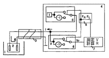
図1〜3は、本発明の第1の実施形態による溶液伝導率測定方法の原理を示す略図である。ここで図1を参照すると、測定システムは、測定される溶液1内に挿入された2極電極2、処理ユニット4、および接続ケーブル3を備える。処理ユニット4は、さらに、矩形形状交流電流を生成する電流源5、同期整流器6、オペレーションユニット7、および2周波数制御ユニット8を備える。図1の電極は、2ワイヤ接続の2極電極を使用し、電流源5は、接続ケーブルを介して矩形形状交流電流を電極の一方に出力する。同期整流器6は、接続ケーブルから応答電極電圧を受け取る。
1-3 are schematic diagrams showing the principle of the solution conductivity measuring method according to the first embodiment of the present invention. Referring now to FIG. 1, the measurement system comprises a
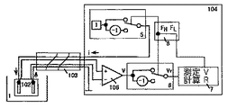
図2に示す4ワイヤ接続の2極電極が使用されてもよいことが留意される。その場合、電極102は、4ワイヤ接続ケーブル103を介して処理ユニット104に接続され、同期整流器6は、増幅器106を介して2つの電極間の測定セルの電圧Vを取り込む。増幅器106に接続された2つのワイヤ内に流れる電流は、増幅器106の入力インピーダンスが非常に高いため無視されることが可能である。さらに、長い接続ケーブル103の導電性ワイヤの抵抗は、矩形形状の交流電流励起が定電流励起と等価であるため無視されることが可能である。
It is noted that a 4-wire connected bipolar electrode as shown in FIG. 2 may be used. In that case, the
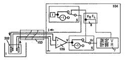
あるいは、図3に示す4ワイヤ接続の4極電極202が利用されることもでき、4極電極202は、処理ユニット104に接続される。この種の4ワイヤ接続は、長い接続ケーブル103の導体抵抗の影響をなくすだけでなく、電極分極の影響もある程度低減することができる。
Alternatively, a 4-wire connection 4-pole electrode 202 shown in FIG. 3 can be used, and the 4-pole electrode 202 is connected to the
上述した異なるタイプの接続の場合、同じ測定方法、すなわち、以降で述べる2周波数法または3電圧法が使用されることが可能である。
いわゆる、2周波数法は、図4〜5に開示され、以下の章で述べられる。
For the different types of connections described above, the same measurement method can be used, ie the two-frequency method or the three-voltage method described below.
The so-called two-frequency method is disclosed in FIGS. 4-5 and described in the following section.
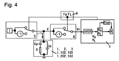
図4は、本発明の第1の実施形態による溶液伝導率測定方法の等価図である。図4では、R=C・G−1は、測定される電極間の抵抗であり、Gは溶液の伝導率であり、Cは電極定数である。コンデンサCPは、電極分極によって生じる等価静電容量を表し、一方、コンデンサCSは、ケーブルの等価静電容量、計器の入力回路の静電容量、および電極の分布静電容量の和を表す。電流Iは、一定振幅、すなわち、IHまたはILであり、周波数FHおよびFLは、2つの励起周波数を表す。電圧Vは、応答電極電圧を表す。Vrは、同期整流プロシージャ後の電圧関数を表す。 FIG. 4 is an equivalent diagram of the solution conductivity measuring method according to the first embodiment of the present invention. In FIG. 4, R = C · G −1 is the resistance between the electrodes to be measured, G is the conductivity of the solution, and C is the electrode constant. Capacitor C P represents the equivalent electrostatic capacitance caused by electrode polarization, while capacitor C S represents the equivalent capacitance of the cable, the capacitance of the input circuit of the meter, and the sum of the distributed capacitance of the electrode . Current I, constant amplitude, that is, I H or I L, the frequency F H and F L represent two excitation frequencies. The voltage V represents the response electrode voltage. Vr represents the voltage function after the synchronous rectification procedure.
第1の実施形態として、2周波数法およびその基本原理がここで簡潔に述べられるであろう。
測定は、所定の周波数の矩形形状の交流電流による励起下で実行される。長いケーブルの静電容量によって生じる誤差は、主に、電流の向き変化の遷移中に導入される。この誤差は、励起の遷移継続期間と半周期期間との比に正比例する。遷移継続期間は、励起周波数が異なっているときでも、2つの測定の間でほとんど同じであるが、半周期期間は、2つの測定の間で異なる。したがって、誤差は、高い周波数と比較して低い周波数に関して小さい。
As a first embodiment, the two-frequency method and its basic principles will now be briefly described.
The measurement is performed under excitation by a rectangular alternating current having a predetermined frequency. Errors caused by long cable capacitance are mainly introduced during the transition of the current direction change. This error is directly proportional to the ratio between the excitation transition duration and the half-cycle period. The transition duration is almost the same between the two measurements even when the excitation frequency is different, but the half-cycle period is different between the two measurements. Thus, the error is small for low frequencies compared to high frequencies.
遷移継続期間がt1であると仮定する。周波数FHの半周期期間は、 Assume that the transition duration is t 1 . The half cycle period of frequency F H is
であり、RHは、周波数FHの矩形形状の交流励起電流に関して測定されたインピーダンスである。同様に、周波数FLの半周期期間は、 Where R H is the impedance measured for a rectangular AC excitation current of frequency F H. Similarly, the half cycle period of the frequency F L is
であり、RLは、周波数FLの矩形形状の交流励起電流に関して測定されたインピーダンスである。 In and, R L is the measured impedance with respect to the alternating excitation current of rectangular frequency F L.
が周波数の比であるとする。
そして、
Is the frequency ratio.
And
および and
であり、 And
である。
特に、n=2の場合、R=2RL−RHである。
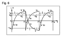
上述した方法は、方法の簡略化した記述にすぎないが、2周波数測定法の本質を理解するのに役立つ。電極間の抵抗Rを正確に確定する方法は、ここで、図4に示す等価回路モデルを参照して詳細に述べられることになり、本発明の第1の実施形態による測定ステップのフローチャートが図5に示され、電流および電圧関数の略図が図6に示される。
It is.
In particular, for n = 2, is R = 2R L -R H.
The method described above is only a simplified description of the method, but helps to understand the nature of the two-frequency measurement method. The method for accurately determining the resistance R between the electrodes will now be described in detail with reference to the equivalent circuit model shown in FIG. 4, and a flowchart of the measurement steps according to the first embodiment of the invention is illustrated. A schematic diagram of the current and voltage function is shown in FIG.
前記方法は、以下のステップを含む。
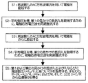
第1ステップS1にて、電極2(102,202)は、ケーブル3(103)を介して矩形形状の交流電流で励起される。図4に示す等価回路を解析することによって、測定セルの電圧Vの関数は、以下に述べるように導出されることが可能である。
The method includes the following steps.
In the first step S1, the electrode 2 (102, 202) is excited by a rectangular alternating current through the cable 3 (103). By analyzing the equivalent circuit shown in FIG. 4, a function of the voltage V of the measurement cell can be derived as described below.
短い測定期間中、電極間の抵抗Rならびに静電容量CSおよびCPは一定であると仮定する。電極は、振幅IHおよび周波数FHの矩形形状の交流電流で励起されると仮定される。電流の正の半周期(t=0からt=THまで)中、iはIHに等しく、静電容量電流則の下で、 During a short measurement period, it is assumed that the resistance R and the capacitance C S and C P between the electrodes is constant. The electrode is assumed to be excited by a rectangular alternating current of amplitude I H and frequency F H. During the positive half cycle of the current (from t = 0 to t = T H), i is equal to I H, under capacitive current law,
および and
である。
さらに、キルヒホッフの電流則によれば、
It is.
Furthermore, according to Kirchhoff's current law,
である。
キルヒホッフの電圧則が、コンデンサCPの両端に適用される場合、
It is.
If Kirchhoff voltage law is applied to both ends of the capacitor C P,
である。 It is.
および and
であるとすると、微分方程式 The differential equation
が取得される。
微分方程式の一般解は、
Is acquired.
The general solution of the differential equation is
![]()
![]()
である。
電極および励起が定常状態にあると仮定すると、
V(t=TH)=−V(t=0)
VP(t=TH)=−VP(t=0)
である。
It is.
Assuming that the electrodes and excitation are in steady state,
V (t = T H ) = − V (t = 0)
V P (t = T H ) = − V P (t = 0)
It is.
![]()
![]()
であるとすると、 If
および and
であり、測定セルの電圧Vの関数は、 And the function of the voltage V of the measurement cell is
である。
ステップS2にて、同期整流が、測定セルの電圧Vに適用されて、第1平均電圧が確定される。その後、第1平均電圧を電流振幅で割ると、第1インピーダンスRHが取得されることになる。数学的式は、以下でより詳細に述べられるであろう。
It is.
In step S2, synchronous rectification is applied to the voltage V of the measuring cell to determine the first average voltage. Thereafter, when the first average voltage is divided by the current amplitude, the first impedance RH is obtained. The mathematical formula will be described in more detail below.
最初に、期間T1→T2の間の電極電圧の平均 First, the average of the electrode voltage during the period T 1 → T 2
は、 Is
を与える。
完全な半周期が平均される場合(T1=0,T2=TH)、第1平均電圧は、
give.
When complete half-cycles are averaged (T 1 = 0, T 2 = T H ), the first average voltage is
であり、ここで、 And where
である。
同期整流を適用することによって、第2の半周期(TH→2TH)の平均電圧は、第1の半周期(0→TH)の平均電圧と同じ、すなわち、同期整流後の電圧関数の総合平均と同じであることになる。第1インピーダンスは、
It is.
By applying a synchronous rectification, the average voltage of the second half period (T H → 2T H) is the same as the first average voltage of half period (0 → T H), i.e., the voltage function after synchronous rectification It is the same as the overall average. The first impedance is
として規定される。
ステップS3にて、別の周波数の矩形形状の交流電流が使用されて、接続ケーブル3を通して電極2が励起される。励起電流が、振幅ILおよび周波数fLを有する矩形形状の交流電流であると仮定すると、fLと第1の矩形形状の交流電流との関係が、fH/fL=nおよびTL/TH=nである場合、測定セルの電圧Vの関数は、同様に、
Is defined as
In step S <b> 3, a rectangular alternating current having another frequency is used to excite the
として導出されることが可能である。
ステップS4にて、同期整流が、測定セルの電圧Vに適用されて、第2平均電圧が確定され、第2平均電圧を電流振幅で割ると、第2インピーダンスRLが確定される。
Can be derived as
In step S4, synchronous rectification is applied to the voltage V of the measurement cell to determine the second average voltage, and dividing the second average voltage by the current amplitude determines the second impedance RL .
同期整流後の平均電圧は、 The average voltage after synchronous rectification is
として表現されることが可能である。
そして、第2インピーダンスは、
Can be expressed as:
And the second impedance is
として規定される。
ステップS5にて、電極間の抵抗Rが、第1および第2インピーダンスRH、RLならびに周波数FHとFLの比nに基づいて計算されることが可能である。測定される溶液の伝導率は、電極定数をさらに組み込むことによって取得されることが可能である。特定の計算は、以下のように表現されることが可能である。
Is defined as
In step S5, the resistance R between the electrodes can be calculated based on the first and second impedances R H , R L and the ratio n of the frequencies F H and F L. The measured conductivity of the solution can be obtained by further incorporating electrode constants. A specific calculation can be expressed as:
2つのインピーダンスの相対差が、 The relative difference between the two impedances is
であるとすると、 If
である。
さらに、結果として、
R=PnwRL+(1−Pnw)RH
となり、ここで、
It is.
Furthermore, as a result,
R = P nw R L + (1-P nw ) RH
Where
である。
通常、式Pnwは、
It is.
Usually, the formula P nw is
であると仮定すると、十分に正確であることになる。その場合、Pnwは、nおよびwの関数である。最初に、nが規定され、次に、関数Pn(w)が、セグメント化多項式当てはめを用いた数値計算法を使用することによって前もって得られることが可能である。特定の方法は、以下のように述べられることが可能である。一連のD値が列挙され、その後、一連のwおよびPn(w)が、それぞれのD値に基づいて導出される。これらの値は、セグメント化多項式当てはめに使用される。測定中、2つのインピーダンスRH、RLの相対差w=(RL−RH)/RHが、最初に計算され、次に、Pnwが計算され、その後、電極間の抵抗Rが得られることが可能である。式G=C/Rを使用することによって、溶液伝導率Gが計算されることが可能である。式中、Cは電極定数である。 Is assumed to be sufficiently accurate. In that case, P nw is a function of n and w. First, n is defined, and then the function P n (w) can be obtained in advance by using a numerical method with segmented polynomial fitting. A particular method can be described as follows. A series of D values is listed, and then a series of w and P n (w) are derived based on the respective D values. These values are used for segmented polynomial fitting. During the measurement, the relative difference between the two impedances R H , RL w = (R L −R H ) / RH is calculated first, then P nw is calculated, and then the resistance R between the electrodes is Can be obtained. By using the formula G = C / R, the solution conductivity G can be calculated. In the formula, C is an electrode constant.
本方法は、理論的には、2つの周波数の比nが1に等しくない限りうまく働くであろう。しかし、実際には、他のランダムな干渉作用を低減するために、周波数比は1.2〜4である、または、その逆数は、すなわち、0.25〜0.84であることが好ましい。 The method will theoretically work as long as the ratio n of the two frequencies is not equal to one. In practice, however, the frequency ratio is preferably 1.2-4, or its reciprocal, i.e., 0.25-0.84, to reduce other random interference effects.
周波数比nの2つの例が以下に示される。
例1、n=2の場合、
w>0.53のとき、
Two examples of the frequency ratio n are shown below.
Example 1, for n = 2,
When w> 0.53
である。
0.11<w<0.53のとき、
Pnw=−1.566025・w4+1.885248・w3−0.042810・w2−0.059616・w+2.004903
である。
w≦0.11のとき、
Pnw=2
である。
It is.
When 0.11 <w <0.53,
P nw = −1.566025 · w 4 + 1.885248 · w 3 −0.042810 · w 2 −0.059616 · w + 2.000493
It is.
When w ≦ 0.11,
P nw = 2
It is.
特に、n=2でかつ In particular, n = 2 and
のとき、R=2RL−RHである。
例2、n=3/2=1.5である場合、
w>0.23のとき、
When a R = 2R L -R H.
Example 2, where n = 3/2 = 1.5
When w> 0.23
である。
0.067<w<0.23のとき、
Pnw=−65.905750・w4+46.746107・w3−6.836475・w2+0.370457・w+2.993219
である。
w≦0.067のとき、
Pnw=3
である。
It is.
When 0.067 <w <0.23,
P nw = −65.905750 · w 4 + 46.746107 · w 3 −6.836475 · w 2 + 0.370457 · w + 2.999319
It is.
When w ≦ 0.067,
P nw = 3
It is.
特に、n=1.5でかつ In particular, n = 1.5 and
のとき、R=3RL−2RHである。
先の式は、実際の精度要件に従って単純化されてもよい。Pnwの不正確な計算によって生じる理論的な相対誤差は、以下のように解析されることが可能である。
When a R = 3R L -2R H.
The previous equation may be simplified according to actual accuracy requirements. The theoretical relative error caused by an inaccurate calculation of P nw can be analyzed as follows.
PnwがPnw1になると仮定すると、相対差は、 Assuming that P nw becomes P nw1 , the relative difference is
である。
数値解析によって、n=2である例1の場合、先の式は、w<0.53wのときのPnwの不正確な計算によって生じるErr<0.01%の理論的な相対誤差を与えることになり、n=1.5である例2の場合、先の式は、w<0.76のときのPnwの不正確な計算によって生じるErr<0.01%の理論的な相対誤差を与えることになると判断されることが可能である。
It is.
By numerical analysis, for example 1 where n = 2, the previous equation gives a theoretical relative error of Err <0.01% caused by an inaccurate calculation of P nw when w <0.53w. Thus, for Example 2 where n = 1.5, the previous equation yields a theoretical relative error of Err <0.01% caused by an inaccurate calculation of P nw when w <0.76. Can be determined.
相対差wが参照値wrefより小さいとき、 When the relative difference w is smaller than the reference value w ref
が使用されることが可能である。
数値解析によれば、n=1.2〜4のとき、以下の推定が使用されることが可能である。
w<−0.0209・n2+0.194・n−0.151(第1参照値)であるか、w<0.15|n=2であるか、またはw<0.09|n=1.5である場合、Pnw=n/(n−1)の不正確な計算によって生じる理論的な相対誤差は、Err<0.02%であることになる。
w<−0.0238・n2+0.247・n−0.197(第2参照値)であるか、w<0.20|n=2であるか、またはw<0.12|n=1.5である場合、Pnw=n/(n−1)の不正確な計算によって生じる理論的な相対誤差は、Err<0.1%であることになる。
Can be used.
According to numerical analysis, when n = 1.2-4, the following estimates can be used.
w <−0.0209 · n 2 + 0.194 · n−0.151 (first reference value), w <0.15 | n = 2, or w <0.09 | n = If 1.5, the theoretical relative error caused by an inaccurate calculation of P nw = n / (n−1) would be Err <0.02%.
w <−0.0238 · n 2 + 0.247 · n−0.197 (second reference value), w <0.20 | n = 2, or w <0.12 | n = If 1.5, the theoretical relative error caused by an inaccurate calculation of P nw = n / (n−1) would be Err <0.1%.
参照値wrefは、計算精度要件に従って選択されることが可能であることが明らかであり、小さな参照値wrefは、公式Pnw=n/(n−1)に従って小さな相対誤差をもたらす。 The reference value w ref, it is clear that calculation is capable of being selected in accordance with accuracy requirements, a small reference value w ref, resulting in a smaller relative error according to the formula P nw = n / (n- 1).
測定中に、IH=IL=Iであると仮定されることが可能であり、したがって、一部の式は、さらに単純化される可能性がある。
本実施形態では、同期整流器6は、マルチプレクススイッチなどのハードウェア回路として実施されることが可能である。2周波数法の場合、式は、平均電圧を使用するだけであるため、同期整流器に続いて、かつ、A/D変換器に先行してローパスフィルタが挿入されることが可能である。これは、A/D変換器についての速度要件を低減することができる。あるいは、同期整流器6は、測定セルの電圧Vの高速A/D変換後に、ソフトウェアで実施されることもできる。
During the measurement, it can be assumed that I H = I L = I, and therefore some equations may be further simplified.
In the present embodiment, the
本発明のさらなる実施形態は、3電圧法と名付けられることが可能であり、かつ、以下の章で述べられる方法を開示する。
A/D変換器の速度が十分に速い場合、単一周波数の矩形形状の交流電流だけを用いて励起することも可能である。電気伝導率の測定精度に対する電極分極および長い接続ケーブルの悪い影響は、以下の測定方法を使用してなくされることもできる。
A further embodiment of the present invention discloses the method that can be named the three voltage method and is described in the following section.
If the speed of the A / D converter is sufficiently high, it is possible to excite using only a single-frequency rectangular AC current. The negative effects of electrode polarization and long connection cables on the measurement accuracy of electrical conductivity can also be eliminated using the following measurement method.
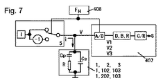
図7は、本発明のさらなる実施形態による溶液伝導率確定のための測定方法の原理を示す略図である。方法は、図4と同様の測定回路を用いてうまく働くが、同期整流器6は省略されることが可能であり、電圧信号は、オペレーションユニット407に直接送出されることが可能である。
FIG. 7 is a schematic diagram illustrating the principle of a measurement method for determining solution conductivity according to a further embodiment of the present invention. The method works well with a measurement circuit similar to FIG. 4, but the
図8は、この実施形態による溶液伝導率確定のための測定方法のステップを示す略フローチャートである。試験システムは、矩形形状の交流励起電流を供給する電流源5、周波数制御ユニット408、および、オペレーションユニット407を備える。
FIG. 8 is a schematic flowchart showing the steps of the measurement method for determining the solution conductivity according to this embodiment. The test system includes a
図7および8を参照すると、本実施形態の方法は、以下のステップを含む。
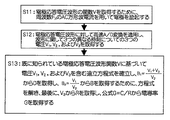
ステップS11にて、ケーブルを通して所定の振幅および所定の周波数の矩形形状の交流電流で電極を励起する。上述したように、正の半周期中における、振幅IHおよび周波数fHを有する矩形形状の交流電流を用いた励起を仮定すると、測定セルの電圧Vの関数は、
7 and 8, the method of this embodiment includes the following steps.
In step S11, the electrode is excited with a rectangular alternating current having a predetermined amplitude and a predetermined frequency through the cable. As described above, assuming excitation using a rectangular alternating current having an amplitude I H and a frequency f H during the positive half cycle, the function of the voltage V of the measurement cell is
である。
電圧関数は、3つの独立した変数D、B、Rを有し、3つの独立した変数D、B、Rは、異なる時刻において3つの電圧を使用することによって、または、異なる期間の間に3つの平均電圧を使用することによって導出されることが可能である。
It is.
The voltage function has three independent variables D, B, R, and the three independent variables D, B, R are either used by using three voltages at different times or during different periods. It can be derived by using two average voltages.
ステップS12にて、測定セルの電圧Vに対して高速A/D変換を適用し、また、交流電流の半分の周期の間で、異なる時刻について3つの電圧または3つの期間について3つの平均電圧を取得する。たとえば、電圧関数Vの、3つの時点(t1,t2,t3)、すなわち、t1=1/4TH、t2=1/2TH、t1=3/4THについて3つの電圧V1、V2、およびV3を得るために、電圧がA/D変換される。
In step S12, high-speed A / D conversion is applied to the voltage V of the measurement cell, and three voltages for different times or three average voltages for three periods are applied during a half period of the alternating current. get. For example, the voltage function V, 3 time points (t 1, t 2, t 3), i.e., t 1 = 1 / 4T H ,
ステップS13にて、測定セルの電圧Vの既に知られている関数 In step S13, the already known function of the voltage V of the measuring cell
に従ってV1、V2、およびV3についての連立方程式を And the simultaneous equations for V 1 , V 2 , and V 3
として確立する。式中、Rは、測定される電極間の抵抗である。
再び、
Establish as. Where R is the resistance between the electrodes being measured.
again,
および and
とする。ここで、THは、周波数FHの半周期である。3つの独立したパラメータR、B、およびDは、連立方程式を解くことによって導出されることが可能である。その後、溶液伝導率Gが、公式G=C/Rから導出されることが可能である。 And Here, T H is a half cycle of the frequency F H. Three independent parameters R, B, and D can be derived by solving simultaneous equations. Thereafter, the solution conductivity G can be derived from the formula G = C / R.
方程式を解く1つの方法は以下に述べられる。 One way to solve the equation is described below.
である。
Dは、B1から導出されることが可能である。
It is.
D can be derived from B 1 .
そして、 And
である。
Bは、B2およびDから
It is.
B from B 2 and D
として容易に導出されることが可能である。ここで、 Can be easily derived as: here,
であり、そして、 And
である。
溶液伝導率Gは、式G=C/Rから導出されることが可能である。式中、Cは電極定数である。
It is.
The solution conductivity G can be derived from the equation G = C / R. In the formula, C is an electrode constant.
別の解法は、ランダム干渉の影響を低減するために、Va1、Va2、およびVa3を取得するための、3つの異なる期間(Δt1,Δt2,Δt3)、たとえば、Δt1=(1/8)→(3/8)TH、Δt2=(3/8)→(5/8)TH、およびΔt3=(5/8)→(7/8)THについての電圧の平均を含む。Va1、Va2、およびVa3が方程式を解くために使用されると、関数Vaは、上述したように使用される。
Another solution is to obtain three different time periods (Δt 1 , Δt 2 , Δt 3 ) for obtaining V a1 , V a2 , and V a3 to reduce the effects of random interference, eg, Δt 1 = (1/8) → (3/8) T H,
その後、3つの連立方程式は、上記のように書かれることが可能であり、再び、Dが、 The three simultaneous equations can then be written as above and again D is
から導出され、Ba2が、 And B a2 is
から導出され、最後に、Rが、Va2から導出される。溶液伝導率Gは、式G=C/Rから導出されることが可能である。
ランダム干渉の影響を低減するために、V1、V2、およびV3またはVa1、Va2、およびVa3が、複数の電圧関数の同じ位相点の電圧を平均することによって計算されることが可能である。符号を反転した後、負の半周期の電圧も計算に使用されることが可能である。V1、V2、およびV3またはVa1、Va2、およびVa3は、3つの未知の値R、B、およびDを得るための連立方程式を構成するのに使用される。ここで、Rは、測定される電極間の抵抗である。
And finally R is derived from V a2 . The solution conductivity G can be derived from the equation G = C / R.
To reduce the effects of random interference, V 1 , V 2 , and V 3 or V a1 , V a2 , and V a3 are calculated by averaging the voltages at the same phase point of multiple voltage functions Is possible. After inverting the sign, a negative half-cycle voltage can also be used in the calculation. V 1 , V 2 , and V 3 or V a1 , V a2 , and V a3 are used to construct simultaneous equations to obtain three unknown values R, B, and D. Here, R is the resistance between the electrodes to be measured.
一般に、上述した、いわゆる2周波数法、または、いわゆる1周波数3電圧法は、所定の測定に関連することが留意される。すなわち、所定の測定の場合、励起は、一対の周波数または単一周波数を用いて行われる。異なる伝導率範囲内の溶液が測定されるとき、適切な励起周波数は異なってもよいことが当業者には明らかである。通常、溶液の伝導率が低ければ低いほど、励起のためにより小さな電流と共に低い周波数が使用される。さらに、溶液の伝導率が、一般に溶液の温度に関連するため、溶液伝導率センサまたは電極内に温度センサが通常含まれる。したがって、センサを処理ユニットに接続するケーブルは、温度センサを接続するワイヤを備えてもよい。温度を測定する回路は、処理ユニット内にも設けられてもよい。すべての述べた原理は、本発明の方法にも適する。 In general, it is noted that the so-called two-frequency method or the so-called one-frequency three-voltage method described above relates to a given measurement. That is, for a given measurement, excitation is performed using a pair of frequencies or a single frequency. It will be apparent to those skilled in the art that the appropriate excitation frequency may be different when solutions in different conductivity ranges are measured. In general, the lower the conductivity of the solution, the lower frequency is used with a smaller current for excitation. In addition, since the conductivity of the solution is generally related to the temperature of the solution, a temperature sensor is usually included within the solution conductivity sensor or electrode. Thus, the cable connecting the sensor to the processing unit may comprise a wire connecting the temperature sensor. A circuit for measuring the temperature may also be provided in the processing unit. All the stated principles are also suitable for the method of the invention.
先の説明で使用された用語、記号、式、および例は、本発明の用途を決して制限せず、本発明の例示の便宜のためのものにすぎない。
本発明の好ましい実施形態では、周波数fgおよびfrならびに交流電流iは、一般的に測定される溶液の中間範囲について選択される。特に、それらは、fg=1kHz、fr=2kHz、およびi=0.1mAであるように選択される。
The terms, symbols, formulas, and examples used in the foregoing description in no way limit the use of the invention and are merely for the convenience of illustration of the invention.
In a preferred embodiment of the present invention, the frequencies f g and f r and the alternating current i are generally selected for the intermediate range of the solution to be measured. In particular, they are selected such that f g = 1 kHz, f r = 2 kHz, and i = 0.1 mA.
上述した実施形態は、本発明の好ましい実施形態を示すだけである。種々の等価な置換および変更が、先の説明に基づいて当業者によって行われることが可能である。
しかし、本発明の実施形態に基づくすべてのこれらの置換および変更は、本発明の精神および添付特許請求項に規定される範囲内に入る。
The above-described embodiments only show preferred embodiments of the invention. Various equivalent substitutions and modifications can be made by those skilled in the art based on the foregoing description.
However, all such substitutions and modifications based on embodiments of the invention fall within the scope defined by the spirit of the invention and the appended claims.
1 溶液
2、102、202 測定セル
3、103 接続ケーブル
4、104 処理ユニット
5 電流源
6 同期整流器
7、407 オペレーションユニット
8、408 周波数制御ユニット
106 増幅器
G 溶液の伝導率
i 交流電流
I 電流源
fH、fL 周波数
V 測定セルの電圧
Vr 同期整流後の電圧
IH、IL 振幅
VH、VL 平均電圧
RH、RL インピーダンス
R 抵抗
n 周波数比
C 電極定数
w 相対差
wref 参照値
Cp、Cs コンデンサ
DESCRIPTION OF
Claims (13)
交流電流(i)を前記測定セル(2,102,202)に印加すること、
前記処理ユニット(4,104)において、前記測定セル(2,102,202)から電圧(V)を測定すること、および、
前記測定セル(2,102,202)の前記電圧(V)から、前記溶液(1)の抵抗(R)および/または電気伝導率(G)を計算することによって、前記溶液(1)の電気伝導率(G)を測定する方法であって、
電流源(5)によって供給され、かつ、前記少なくとも1つの測定セル(2,102,202)に印加される前記交流電流(i)が、実質的に矩形形状であること、前記接続ケーブル(3)の容量性作用が、方程式に含まれること、前記溶液(1)の抵抗(R)および/または電気伝導率(G)が、計算ユニット(7)によって前記方程式を解くことによって確定されること、前記測定セル(2,102,202)の前記電圧(V)が、少なくとも3つの異なる時点(t1,t2,t3)で測定されて、少なくとも3つの電圧値(V1,V2,V3)が確定されること、および、前記抵抗(R)が、前記少なくとも3つの電圧値(V1,V2,V3)のそれぞれについて前記測定セル(2,102,202)の前記電圧(V)の時間依存関数によって与えられる少なくとも3つの方程式を同時に解くことによって計算されること、を特徴とする方法。 With a measuring device comprising at least one measuring cell (2, 102, 202) in contact with the solution (1) and connected to the processing unit (4, 104) via the connecting cable (3)
Applying an alternating current (i) to the measuring cell (2, 102, 202);
Measuring the voltage (V) from the measurement cell (2, 102, 202) in the processing unit (4, 104); and
By calculating the resistance (R) and / or the electrical conductivity (G) of the solution (1) from the voltage (V) of the measurement cell (2, 102, 202), the electric power of the solution (1) A method for measuring conductivity (G), comprising:
The alternating current (i) supplied by the current source (5) and applied to the at least one measuring cell (2, 102, 202) is substantially rectangular, the connecting cable (3 ) Is included in the equation, and the resistance (R) and / or electrical conductivity (G) of the solution (1) is determined by solving the equation by the calculation unit (7) The voltage (V) of the measurement cell (2, 102, 202) is measured at at least three different time points (t 1 , t 2 , t 3 ) and at least three voltage values (V 1 , V 2). , V 3 ) is determined, and the resistance (R) is set to the measurement cell (2, 102, 202) for each of the at least three voltage values (V 1 , V 2 , V 3 ). Of voltage (V) Be calculated by solving at least three equations given simultaneously by between dependent function, wherein the.
前記計算ユニット(7,407)が、少なくとも3つの電圧値(V1,V2,V3)のそれぞれについて前記測定セル(2,102,202)の前記電圧(V)の依存関数によって与えられる少なくとも3つの方程式を同時に解くことによって、前記抵抗(R)を計算するのに適した計算ユニット(7)を備えることを特徴とする測定デバイス。 At least one measuring cell (2, 102, 202), in contact with the solution (1) and connected to the processing unit (4, 104) via the connection cable (3), said measuring cell (2 , 102, 202) and is suitable for measuring the voltage (V) of the solution (1) from the voltage (V) of the measuring cell (2, 102, 202). Or a device for measuring the electrical conductivity of the solution (1) using at least one measuring cell (2, 102, 202), suitable for determining the corresponding electrical conductivity (G), comprising: A current source (5) for supplying a rectangular-shaped alternating current (i) to the power source, and the equation including the capacitive action of the connecting cable (3) to solve for the measurement cell (2, 102, 202) From the voltage (V), the With the resistance of the liquid (1) (R) and / or electrical conductivity calculation unit for calculating the (G) (7),
The calculation unit (7,407) is given by the dependence function of the voltage (V) of the measuring cell (2,102, 202) for each of at least three voltage values (V 1 , V 2 , V 3 ). A measuring device comprising a calculation unit (7) suitable for calculating said resistance (R) by solving at least three equations simultaneously.
Applications Claiming Priority (3)
| Application Number | Priority Date | Filing Date | Title |
|---|---|---|---|
| CNB2006100305556A CN100541208C (en) | 2006-08-30 | 2006-08-30 | The measuring method of electrical conductivity of solution |
| CN200610030555.6 | 2006-08-30 | ||
| PCT/EP2007/058946 WO2008025775A1 (en) | 2006-08-30 | 2007-08-28 | A method for measuring the electrical conductivity of solutions |
Publications (2)
| Publication Number | Publication Date |
|---|---|
| JP2010501872A JP2010501872A (en) | 2010-01-21 |
| JP5312326B2 true JP5312326B2 (en) | 2013-10-09 |
Family
ID=38692141
Family Applications (1)
| Application Number | Title | Priority Date | Filing Date |
|---|---|---|---|
| JP2009526085A Active JP5312326B2 (en) | 2006-08-30 | 2007-08-28 | Method for measuring the electrical conductivity of a solution |
Country Status (5)
| Country | Link |
|---|---|
| US (1) | US8521442B2 (en) |
| EP (1) | EP2057475A1 (en) |
| JP (1) | JP5312326B2 (en) |
| CN (1) | CN100541208C (en) |
| WO (1) | WO2008025775A1 (en) |
Cited By (1)
| Publication number | Priority date | Publication date | Assignee | Title |
|---|---|---|---|---|
| TWI683075B (en) | 2017-02-24 | 2020-01-21 | 日商松下知識產權經營股份有限公司 | Heating conditioner and steam conditioning method |
Families Citing this family (37)
| Publication number | Priority date | Publication date | Assignee | Title |
|---|---|---|---|---|
| CN101561466B (en) * | 2008-04-18 | 2011-01-26 | 中国科学院金属研究所 | Eddy conductivity measuring method |
| CN101629924B (en) * | 2008-07-14 | 2013-01-30 | 梅特勒-托利多仪器(上海)有限公司 | Input circuit for measuring electromagnetic solution conductivity |
| CN101629923B (en) * | 2008-07-14 | 2013-05-15 | 梅特勒-托利多仪器(上海)有限公司 | Method and device for electromagnetically measuring solution conductivity |
| JP5444857B2 (en) * | 2009-06-02 | 2014-03-19 | 横河電機株式会社 | Electrochemical reaction measuring method and electrochemical reaction measuring device |
| CN102141534B (en) * | 2011-01-18 | 2013-09-04 | 中国地质调查局水文地质环境地质调查中心 | Seawater invasion monitoring method and distributed conductivity geological disaster monitoring device |
| CN103797359B (en) * | 2011-07-20 | 2016-06-01 | 奥普特克-丹奴拉特有限责任公司 | For measuring the device of the electrical conductivity of liquid medium |
| CN102809697B (en) * | 2012-08-24 | 2014-09-03 | 福建师范大学 | Solution conductivity measurement method for excitation of triangular wave and integrating treatment of response current |
| CN102830141B (en) * | 2012-08-24 | 2014-06-25 | 福建师范大学 | Method for measuring solution conductivity of closed decoupled capacitance-resistance network excited by triangular wave |
| CN102809699B (en) * | 2012-08-24 | 2014-09-03 | 福建师范大学 | Dynamic measurement method for distributed capacitance of electrode concerned in measurement of conductivity of solution |
| CN102818936B (en) * | 2012-08-24 | 2014-09-03 | 福建师范大学 | Dynamic testing method for triangular wave excited conductivity cell electrode distribution capacitance |
| CN102830143B (en) * | 2012-08-24 | 2014-03-12 | 福建师范大学 | Method for measuring solution conductivity through triangular wave excitation and integral processing |
| CN102798763B (en) * | 2012-08-24 | 2014-10-15 | 福建师范大学 | Method for measuring conductivity of solution by adopting two waveform excitation signals |
| CN102830142A (en) * | 2012-08-24 | 2012-12-19 | 福建师范大学 | Method and key circuit for measuring solution conductivity through triangular wave excitation |
| CN103048546A (en) * | 2012-12-11 | 2013-04-17 | 南京化工职业技术学院 | Input circuit for measuring liquid electricity conductivity |
| US9116099B2 (en) * | 2012-12-27 | 2015-08-25 | General Electric Company | Wide dynamic range conductivity measurements in water |
| US9410910B1 (en) | 2013-05-23 | 2016-08-09 | D-2 Inc. | Hybrid conductivity sensor |
| CN103424629B (en) * | 2013-07-25 | 2016-04-13 | 同济大学 | A kind of simple and easy method testing impedance of graphene oxide solution |
| CN103728498B (en) * | 2013-10-29 | 2015-12-02 | 高玉琴 | A kind of conductivity/freq converting circuit |
| GB2538924B (en) * | 2014-03-17 | 2020-12-02 | Atlas Scient Llc | Driving circuit for a conductivity sensor |
| TWI692274B (en) | 2014-05-21 | 2020-04-21 | 瑞士商菲利浦莫里斯製品股份有限公司 | Inductive heating device for heating an aerosol-forming substrate and method of operating an inductive heating system |
| CN105371906B (en) * | 2014-08-29 | 2020-10-13 | 桓达科技股份有限公司 | Electromagnetic flowmeter with frequency conversion type liquid conductivity measuring function |
| CN105444822A (en) * | 2014-08-29 | 2016-03-30 | 桓达科技股份有限公司 | Electromagnetic flow meter with amplitude modulation type measurement function for measuring electrical conductivity of pipeline liquid |
| CN105588983B (en) * | 2014-11-14 | 2021-04-23 | 佛山市顺德区美的电热电器制造有限公司 | Conductivity testing device and electric equipment |
| CN105067893B (en) * | 2015-08-19 | 2017-10-17 | 大连理工大学 | Solution resistance flexible measurement method based on conductance cell second order model |
| CN107490726A (en) * | 2016-06-12 | 2017-12-19 | 天津工业大学 | A kind of liquid or gel impedance bioelectrical measurement system and its information acquisition method |
| US10352887B1 (en) * | 2016-06-22 | 2019-07-16 | Ronald W. Parker | Conductivity measurement methods and systesms |
| CN107228886B (en) * | 2017-04-24 | 2019-09-10 | 费尔德(北京)科学仪器有限公司 | The measuring device and method of the conductivity Resistivity testing of water |
| US10598623B2 (en) | 2017-05-24 | 2020-03-24 | Rosemount Aerospace Inc. | Four-wire conductivity cell circuit |
| US10571419B2 (en) | 2017-05-24 | 2020-02-25 | Rosemount Aerospace Inc. | Contacting type flow through conductivity cell |
| CN107064225B (en) * | 2017-05-24 | 2023-03-07 | 华侨大学 | Intelligent water quality detection system based on dual-mode self-adjustment conductivity detection |
| CN108761209A (en) * | 2018-07-19 | 2018-11-06 | 浙江维思无线网络技术有限公司 | A kind of liquid electric conductivity measurement method and device |
| CN109142463A (en) * | 2018-10-09 | 2019-01-04 | 李晨天 | Transient DC method for measuring conductance and device |
| CN109490636B (en) * | 2018-12-26 | 2024-04-26 | 上海简逸生物科技有限公司 | Conductivity change tester for solution freezing and thawing process |
| US10605642B1 (en) * | 2019-11-27 | 2020-03-31 | Altec Industries, Inc. | Conductive liquid sensing system |
| DE102021107765A1 (en) * | 2021-03-26 | 2022-09-29 | Endress+Hauser Conducta Gmbh+Co. Kg | Method for measuring the conductivity of a medium |
| CN114113228A (en) * | 2021-11-03 | 2022-03-01 | 元能科技(厦门)有限公司 | Method for evaluating coating uniformity of battery pole piece |
| CN114113839A (en) * | 2021-11-16 | 2022-03-01 | 武汉昊诚锂电科技股份有限公司 | Method for evaluating current collecting capacity of lithium-ion battery current collecting structure |
Family Cites Families (15)
| Publication number | Priority date | Publication date | Assignee | Title |
|---|---|---|---|---|
| US4683435A (en) * | 1985-01-09 | 1987-07-28 | Anatel Instrument Corporation | Circuit for compensating non-linearities in electrolyte conductivity measurement system |
| DE3517772A1 (en) * | 1985-05-17 | 1986-11-20 | Dr. A. Kuntze GmbH & Co KG, 4000 Düsseldorf | Method for measuring the electrolytic conductivity of fluids |
| JPH0715490B2 (en) * | 1986-03-10 | 1995-02-22 | 横河電機株式会社 | Conductivity meter circuit |
| US4808930A (en) | 1986-09-03 | 1989-02-28 | Beckman Industrial Corporation | Technique of compensating for capacitive effects in conductivity measurements |
| JPH079410B2 (en) * | 1990-01-14 | 1995-02-01 | 株式会社堀場製作所 | Conductivity measuring device |
| US5260663A (en) * | 1992-07-14 | 1993-11-09 | Anatel Corporation | Methods and circuits for measuring the conductivity of solutions |
| DE4233110A1 (en) * | 1992-10-02 | 1994-04-07 | Knick Elektronische Mesgeraete | Measuring electrical conductivity of liquids, esp. electrolytes - comparing conductivity values obtained for two different ac current frequencies to detect measurement errors |
| US5708363A (en) * | 1995-10-16 | 1998-01-13 | Signet Scientific Company | Liquid conductivity measurement system using a variable-frequency AC voltage |
| FR2766271B1 (en) * | 1997-07-16 | 1999-10-01 | Zellweger Analytics | METHOD AND DEVICE FOR MEASURING THE CONDUCTIVITY OF A SOLUTION PROVIDING CONTROL OF THE POLARIZATION OF ELECTRODES |
| EP0911639A1 (en) * | 1997-10-21 | 1999-04-28 | Whirlpool Corporation | Method and device for compensating the signal drift in a conductivity cell used in a domestic appliance |
| DE19815922A1 (en) * | 1998-04-09 | 1999-10-14 | Knick Elektronische Mesgeraete | Measuring conductance of liquids, especially electrolyte |
| DE19844489A1 (en) | 1998-09-29 | 2000-03-30 | Conducta Endress & Hauser | Method for determining the electrical conductivity of liquids |
| CN1203311C (en) | 2002-05-24 | 2005-05-25 | 梅特勒-托利多仪器(上海)有限公司 | Method of measuring solution electroconductivity |
| JP2004219326A (en) * | 2003-01-16 | 2004-08-05 | Railway Technical Res Inst | Cell and method for measuring electrical conductivity |
| CN1285904C (en) | 2004-12-07 | 2006-11-22 | 苏州大学 | Measuring method of electroconductirity of water |
-
2006
- 2006-08-30 CN CNB2006100305556A patent/CN100541208C/en active Active
-
2007
- 2007-08-28 JP JP2009526085A patent/JP5312326B2/en active Active
- 2007-08-28 WO PCT/EP2007/058946 patent/WO2008025775A1/en active Application Filing
- 2007-08-28 EP EP07802963A patent/EP2057475A1/en not_active Withdrawn
-
2008
- 2008-12-12 US US12/333,595 patent/US8521442B2/en active Active
Cited By (2)
| Publication number | Priority date | Publication date | Assignee | Title |
|---|---|---|---|---|
| TWI683075B (en) | 2017-02-24 | 2020-01-21 | 日商松下知識產權經營股份有限公司 | Heating conditioner and steam conditioning method |
| CN110268198B (en) * | 2017-02-24 | 2021-07-16 | 松下知识产权经营株式会社 | Heating cooker and steam cooking method |
Also Published As
| Publication number | Publication date |
|---|---|
| EP2057475A1 (en) | 2009-05-13 |
| CN101135705A (en) | 2008-03-05 |
| CN100541208C (en) | 2009-09-16 |
| WO2008025775A1 (en) | 2008-03-06 |
| JP2010501872A (en) | 2010-01-21 |
| US20090125250A1 (en) | 2009-05-14 |
| US8521442B2 (en) | 2013-08-27 |
Similar Documents
| Publication | Publication Date | Title |
|---|---|---|
| JP5312326B2 (en) | Method for measuring the electrical conductivity of a solution | |
| JP6948291B2 (en) | Calibration system for voltage measuring equipment | |
| JP7199866B2 (en) | Polyphase measurement device and method of operation | |
| JP7210916B2 (en) | electromagnetic flow meter | |
| WO2020095471A1 (en) | Impedance measurement device | |
| JP2003028900A (en) | Non-contact voltage measurement method and apparatus | |
| TW202001249A (en) | Multi-sensor configuration for non-contact voltage measurement devices | |
| JP5940389B2 (en) | AC resistance measuring device and AC resistance measuring method | |
| JP2015224886A (en) | Device and method for measuring voltage | |
| JPH09243683A (en) | Method and device for measurement of resistivity, electric conductivity and/or permittivity | |
| JP2015014469A (en) | Resistance measurement device and resistance measurement method | |
| JP3964538B2 (en) | Impedance measuring device | |
| JP2004177310A (en) | Dielectric loss tangent-measuring device and non-contact voltage measuring device using the same | |
| KR102564785B1 (en) | Apparatus and method for generating virtual neutral point of three-phase three-wire system | |
| JPH0450542Y2 (en) | ||
| JPH05297038A (en) | Grounding-resistance testing instrument | |
| CN103713185A (en) | Motor terminal voltage measuring instrument of alternating current frequency conversion motor | |
| JP3255817B2 (en) | Ion concentration measurement device | |
| KR20070006020A (en) | Body fat analysis technique using multi-frequency bipolar-electrode method | |
| JPH1062463A (en) | Method for measuring contact resistance of biological signal measuring electrode | |
| JPS6157849A (en) | Method and device for corrosion of metal by digital fourier integration method | |
| JPH0677038B2 (en) | Conductivity measurement method | |
| JPH04131764U (en) | Ion concentration measuring device | |
| RU2478214C1 (en) | Bridge converter of film resistance | |
| JP4500294B2 (en) | Method and apparatus for detecting disconnection position of power cable |
Legal Events
| Date | Code | Title | Description |
|---|---|---|---|
| A621 | Written request for application examination |
Free format text: JAPANESE INTERMEDIATE CODE: A621 Effective date: 20100716 |
|
| A131 | Notification of reasons for refusal |
Free format text: JAPANESE INTERMEDIATE CODE: A131 Effective date: 20120523 |
|
| A601 | Written request for extension of time |
Free format text: JAPANESE INTERMEDIATE CODE: A601 Effective date: 20120713 |
|
| A602 | Written permission of extension of time |
Free format text: JAPANESE INTERMEDIATE CODE: A602 Effective date: 20120723 |
|
| A521 | Request for written amendment filed |
Free format text: JAPANESE INTERMEDIATE CODE: A523 Effective date: 20121019 |
|
| A131 | Notification of reasons for refusal |
Free format text: JAPANESE INTERMEDIATE CODE: A131 Effective date: 20130123 |
|
| A521 | Request for written amendment filed |
Free format text: JAPANESE INTERMEDIATE CODE: A523 Effective date: 20130410 |
|
| TRDD | Decision of grant or rejection written | ||
| A01 | Written decision to grant a patent or to grant a registration (utility model) |
Free format text: JAPANESE INTERMEDIATE CODE: A01 Effective date: 20130603 |
|
| A61 | First payment of annual fees (during grant procedure) |
Free format text: JAPANESE INTERMEDIATE CODE: A61 Effective date: 20130702 |
|
| R150 | Certificate of patent or registration of utility model |
Free format text: JAPANESE INTERMEDIATE CODE: R150 Ref document number: 5312326 Country of ref document: JP Free format text: JAPANESE INTERMEDIATE CODE: R150 |
|
| S533 | Written request for registration of change of name |
Free format text: JAPANESE INTERMEDIATE CODE: R313533 |
|
| R350 | Written notification of registration of transfer |
Free format text: JAPANESE INTERMEDIATE CODE: R350 |
|
| R250 | Receipt of annual fees |
Free format text: JAPANESE INTERMEDIATE CODE: R250 |
|
| R250 | Receipt of annual fees |
Free format text: JAPANESE INTERMEDIATE CODE: R250 |
|
| R250 | Receipt of annual fees |
Free format text: JAPANESE INTERMEDIATE CODE: R250 |
|
| R250 | Receipt of annual fees |
Free format text: JAPANESE INTERMEDIATE CODE: R250 |
|
| R250 | Receipt of annual fees |
Free format text: JAPANESE INTERMEDIATE CODE: R250 |
|
| R250 | Receipt of annual fees |
Free format text: JAPANESE INTERMEDIATE CODE: R250 |
|
| R250 | Receipt of annual fees |
Free format text: JAPANESE INTERMEDIATE CODE: R250 |
|
| R250 | Receipt of annual fees |
Free format text: JAPANESE INTERMEDIATE CODE: R250 |