JP5307140B2 - Batteries consisting of multiple cells positioned and interconnected without welding - Google Patents
Batteries consisting of multiple cells positioned and interconnected without welding Download PDFInfo
- Publication number
- JP5307140B2 JP5307140B2 JP2010523557A JP2010523557A JP5307140B2 JP 5307140 B2 JP5307140 B2 JP 5307140B2 JP 2010523557 A JP2010523557 A JP 2010523557A JP 2010523557 A JP2010523557 A JP 2010523557A JP 5307140 B2 JP5307140 B2 JP 5307140B2
- Authority
- JP
- Japan
- Prior art keywords
- contact
- battery
- cell
- battery according
- cells
- Prior art date
- Legal status (The legal status is an assumption and is not a legal conclusion. Google has not performed a legal analysis and makes no representation as to the accuracy of the status listed.)
- Expired - Fee Related
Links
Images


Classifications
-
- H—ELECTRICITY
- H01—ELECTRIC ELEMENTS
- H01M—PROCESSES OR MEANS, e.g. BATTERIES, FOR THE DIRECT CONVERSION OF CHEMICAL ENERGY INTO ELECTRICAL ENERGY
- H01M50/00—Constructional details or processes of manufacture of the non-active parts of electrochemical cells other than fuel cells, e.g. hybrid cells
- H01M50/20—Mountings; Secondary casings or frames; Racks, modules or packs; Suspension devices; Shock absorbers; Transport or carrying devices; Holders
-
- H—ELECTRICITY
- H01—ELECTRIC ELEMENTS
- H01M—PROCESSES OR MEANS, e.g. BATTERIES, FOR THE DIRECT CONVERSION OF CHEMICAL ENERGY INTO ELECTRICAL ENERGY
- H01M10/00—Secondary cells; Manufacture thereof
- H01M10/60—Heating or cooling; Temperature control
- H01M10/61—Types of temperature control
- H01M10/613—Cooling or keeping cold
-
- H—ELECTRICITY
- H01—ELECTRIC ELEMENTS
- H01M—PROCESSES OR MEANS, e.g. BATTERIES, FOR THE DIRECT CONVERSION OF CHEMICAL ENERGY INTO ELECTRICAL ENERGY
- H01M10/00—Secondary cells; Manufacture thereof
- H01M10/60—Heating or cooling; Temperature control
- H01M10/64—Heating or cooling; Temperature control characterised by the shape of the cells
- H01M10/643—Cylindrical cells
-
- H—ELECTRICITY
- H01—ELECTRIC ELEMENTS
- H01M—PROCESSES OR MEANS, e.g. BATTERIES, FOR THE DIRECT CONVERSION OF CHEMICAL ENERGY INTO ELECTRICAL ENERGY
- H01M10/00—Secondary cells; Manufacture thereof
- H01M10/60—Heating or cooling; Temperature control
- H01M10/64—Heating or cooling; Temperature control characterised by the shape of the cells
- H01M10/647—Prismatic or flat cells, e.g. pouch cells
-
- H—ELECTRICITY
- H01—ELECTRIC ELEMENTS
- H01M—PROCESSES OR MEANS, e.g. BATTERIES, FOR THE DIRECT CONVERSION OF CHEMICAL ENERGY INTO ELECTRICAL ENERGY
- H01M10/00—Secondary cells; Manufacture thereof
- H01M10/60—Heating or cooling; Temperature control
- H01M10/65—Means for temperature control structurally associated with the cells
- H01M10/655—Solid structures for heat exchange or heat conduction
- H01M10/6556—Solid parts with flow channel passages or pipes for heat exchange
- H01M10/6557—Solid parts with flow channel passages or pipes for heat exchange arranged between the cells
-
- H—ELECTRICITY
- H01—ELECTRIC ELEMENTS
- H01M—PROCESSES OR MEANS, e.g. BATTERIES, FOR THE DIRECT CONVERSION OF CHEMICAL ENERGY INTO ELECTRICAL ENERGY
- H01M10/00—Secondary cells; Manufacture thereof
- H01M10/60—Heating or cooling; Temperature control
- H01M10/65—Means for temperature control structurally associated with the cells
- H01M10/656—Means for temperature control structurally associated with the cells characterised by the type of heat-exchange fluid
- H01M10/6561—Gases
- H01M10/6566—Means within the gas flow to guide the flow around one or more cells, e.g. manifolds, baffles or other barriers
-
- H—ELECTRICITY
- H01—ELECTRIC ELEMENTS
- H01M—PROCESSES OR MEANS, e.g. BATTERIES, FOR THE DIRECT CONVERSION OF CHEMICAL ENERGY INTO ELECTRICAL ENERGY
- H01M50/00—Constructional details or processes of manufacture of the non-active parts of electrochemical cells other than fuel cells, e.g. hybrid cells
- H01M50/20—Mountings; Secondary casings or frames; Racks, modules or packs; Suspension devices; Shock absorbers; Transport or carrying devices; Holders
- H01M50/204—Racks, modules or packs for multiple batteries or multiple cells
- H01M50/207—Racks, modules or packs for multiple batteries or multiple cells characterised by their shape
- H01M50/209—Racks, modules or packs for multiple batteries or multiple cells characterised by their shape adapted for prismatic or rectangular cells
-
- H—ELECTRICITY
- H01—ELECTRIC ELEMENTS
- H01M—PROCESSES OR MEANS, e.g. BATTERIES, FOR THE DIRECT CONVERSION OF CHEMICAL ENERGY INTO ELECTRICAL ENERGY
- H01M50/00—Constructional details or processes of manufacture of the non-active parts of electrochemical cells other than fuel cells, e.g. hybrid cells
- H01M50/20—Mountings; Secondary casings or frames; Racks, modules or packs; Suspension devices; Shock absorbers; Transport or carrying devices; Holders
- H01M50/204—Racks, modules or packs for multiple batteries or multiple cells
- H01M50/207—Racks, modules or packs for multiple batteries or multiple cells characterised by their shape
- H01M50/213—Racks, modules or packs for multiple batteries or multiple cells characterised by their shape adapted for cells having curved cross-section, e.g. round or elliptic
-
- H—ELECTRICITY
- H01—ELECTRIC ELEMENTS
- H01M—PROCESSES OR MEANS, e.g. BATTERIES, FOR THE DIRECT CONVERSION OF CHEMICAL ENERGY INTO ELECTRICAL ENERGY
- H01M50/00—Constructional details or processes of manufacture of the non-active parts of electrochemical cells other than fuel cells, e.g. hybrid cells
- H01M50/50—Current conducting connections for cells or batteries
- H01M50/502—Interconnectors for connecting terminals of adjacent batteries; Interconnectors for connecting cells outside a battery casing
- H01M50/503—Interconnectors for connecting terminals of adjacent batteries; Interconnectors for connecting cells outside a battery casing characterised by the shape of the interconnectors
-
- H—ELECTRICITY
- H01—ELECTRIC ELEMENTS
- H01M—PROCESSES OR MEANS, e.g. BATTERIES, FOR THE DIRECT CONVERSION OF CHEMICAL ENERGY INTO ELECTRICAL ENERGY
- H01M50/00—Constructional details or processes of manufacture of the non-active parts of electrochemical cells other than fuel cells, e.g. hybrid cells
- H01M50/50—Current conducting connections for cells or batteries
- H01M50/502—Interconnectors for connecting terminals of adjacent batteries; Interconnectors for connecting cells outside a battery casing
- H01M50/509—Interconnectors for connecting terminals of adjacent batteries; Interconnectors for connecting cells outside a battery casing characterised by the type of connection, e.g. mixed connections
-
- H—ELECTRICITY
- H01—ELECTRIC ELEMENTS
- H01M—PROCESSES OR MEANS, e.g. BATTERIES, FOR THE DIRECT CONVERSION OF CHEMICAL ENERGY INTO ELECTRICAL ENERGY
- H01M50/00—Constructional details or processes of manufacture of the non-active parts of electrochemical cells other than fuel cells, e.g. hybrid cells
- H01M50/50—Current conducting connections for cells or batteries
- H01M50/502—Interconnectors for connecting terminals of adjacent batteries; Interconnectors for connecting cells outside a battery casing
- H01M50/514—Methods for interconnecting adjacent batteries or cells
- H01M50/517—Methods for interconnecting adjacent batteries or cells by fixing means, e.g. screws, rivets or bolts
-
- H—ELECTRICITY
- H01—ELECTRIC ELEMENTS
- H01M—PROCESSES OR MEANS, e.g. BATTERIES, FOR THE DIRECT CONVERSION OF CHEMICAL ENERGY INTO ELECTRICAL ENERGY
- H01M50/00—Constructional details or processes of manufacture of the non-active parts of electrochemical cells other than fuel cells, e.g. hybrid cells
- H01M50/50—Current conducting connections for cells or batteries
- H01M50/502—Interconnectors for connecting terminals of adjacent batteries; Interconnectors for connecting cells outside a battery casing
- H01M50/521—Interconnectors for connecting terminals of adjacent batteries; Interconnectors for connecting cells outside a battery casing characterised by the material
- H01M50/522—Inorganic material
-
- H—ELECTRICITY
- H01—ELECTRIC ELEMENTS
- H01M—PROCESSES OR MEANS, e.g. BATTERIES, FOR THE DIRECT CONVERSION OF CHEMICAL ENERGY INTO ELECTRICAL ENERGY
- H01M50/00—Constructional details or processes of manufacture of the non-active parts of electrochemical cells other than fuel cells, e.g. hybrid cells
- H01M50/50—Current conducting connections for cells or batteries
- H01M50/571—Methods or arrangements for affording protection against corrosion; Selection of materials therefor
-
- H—ELECTRICITY
- H01—ELECTRIC ELEMENTS
- H01M—PROCESSES OR MEANS, e.g. BATTERIES, FOR THE DIRECT CONVERSION OF CHEMICAL ENERGY INTO ELECTRICAL ENERGY
- H01M10/00—Secondary cells; Manufacture thereof
- H01M10/05—Accumulators with non-aqueous electrolyte
- H01M10/052—Li-accumulators
-
- Y—GENERAL TAGGING OF NEW TECHNOLOGICAL DEVELOPMENTS; GENERAL TAGGING OF CROSS-SECTIONAL TECHNOLOGIES SPANNING OVER SEVERAL SECTIONS OF THE IPC; TECHNICAL SUBJECTS COVERED BY FORMER USPC CROSS-REFERENCE ART COLLECTIONS [XRACs] AND DIGESTS
- Y02—TECHNOLOGIES OR APPLICATIONS FOR MITIGATION OR ADAPTATION AGAINST CLIMATE CHANGE
- Y02E—REDUCTION OF GREENHOUSE GAS [GHG] EMISSIONS, RELATED TO ENERGY GENERATION, TRANSMISSION OR DISTRIBUTION
- Y02E60/00—Enabling technologies; Technologies with a potential or indirect contribution to GHG emissions mitigation
- Y02E60/10—Energy storage using batteries
-
- Y—GENERAL TAGGING OF NEW TECHNOLOGICAL DEVELOPMENTS; GENERAL TAGGING OF CROSS-SECTIONAL TECHNOLOGIES SPANNING OVER SEVERAL SECTIONS OF THE IPC; TECHNICAL SUBJECTS COVERED BY FORMER USPC CROSS-REFERENCE ART COLLECTIONS [XRACs] AND DIGESTS
- Y02—TECHNOLOGIES OR APPLICATIONS FOR MITIGATION OR ADAPTATION AGAINST CLIMATE CHANGE
- Y02P—CLIMATE CHANGE MITIGATION TECHNOLOGIES IN THE PRODUCTION OR PROCESSING OF GOODS
- Y02P70/00—Climate change mitigation technologies in the production process for final industrial or consumer products
- Y02P70/50—Manufacturing or production processes characterised by the final manufactured product
Abstract
Description
本発明は、溶接なしに位置決め相互接続される円柱形または角柱形の複数のセルからなる電池に関する。 The present invention relates to a battery comprising a plurality of cylindrical or prismatic cells that are positioned and interconnected without welding.
現在の電池、特に、電動工具の駆動に必要な電気エネルギーを保存するための電池は、多数(時には約100個)の素子から構成され、これらの素子は、前記素子の端子に溶接される導電性ブレードからなる接点により電気的に相互接続され、素子は絶縁体により隔てられて接着テープによりパックとして組み立てられる。このような電池を実現するには、面倒で時間と費用のかかる接続が必要である。さらに、このような電池は、アフターサービスまたはメンテナンスサービスによって1つまたは複数の素子の故障が判明した場合に、これを交換することができない。 Current batteries, particularly batteries for storing electrical energy required to drive a power tool, are composed of a large number (sometimes about 100) of elements that are welded to the terminals of the elements. The elements are electrically interconnected by contacts made of conductive blades, and the elements are separated by an insulator and assembled as a pack with adhesive tape. Realizing such a battery requires cumbersome, time consuming and expensive connections. Further, such batteries cannot be replaced if one or more element failures are found by after-sales or maintenance services.
少ない数の素子から構成されて、カメラ、写真機、レーザプレーヤ等の携帯式小型装置の動作に必要な電気エネルギーを供給する電池の製造に用いる場合は、溶接のない電池が提案されており(米国特許第5096788号明細書)、この電池は、
カバーを有するハウジングと、
上と下の列の1組のプレートに配置されて前記ハウジング内に収容され、各セルが正極の端子と負極の端子とを有する複数のセルと、
複数のセル同士を相互接続させる単一の導電性シートからなる可撓性の回路と、
ハウジングの底の内面と前記可撓性の導電性シートの一部との間に配置された第1の押圧素子および、カバーと可撓性の導電性シートの他の部分との間に配置された第2の押圧素子とを有し、前記第1および第2の押圧素子の各々が弾性のフィンガを備え、前記弾性のフィンガが、正極および負極に向かって傾斜し、それによって、前記導電性シートの対向部分を前記端子に当接させて、前記複数のセルの相互接続を実施するようにしている。
A battery without welding has been proposed when it is used to manufacture a battery that is composed of a small number of elements and supplies electric energy necessary for the operation of a portable small device such as a camera, a camera, or a laser player ( US Pat. No. 5,096,788), this battery is
A housing having a cover;
A plurality of cells disposed in a set of plates in an upper and lower row and housed in the housing, each cell having a positive terminal and a negative terminal;
A flexible circuit consisting of a single conductive sheet interconnecting a plurality of cells;
A first pressing element disposed between an inner surface of the bottom of the housing and a part of the flexible conductive sheet; and a cover and the other part of the flexible conductive sheet. Each of the first and second pressing elements includes an elastic finger, and the elastic finger is inclined toward the positive electrode and the negative electrode, whereby the conductive The opposite portions of the sheet are brought into contact with the terminals to interconnect the plurality of cells.
多数のセルからなる電池にこうした装置を適用することは検討可能だとは思えない。なぜなら、このような用途では、この種の装置が、以下のような致命的な欠点を少なくとも有するからである。
並列接続により組み立てられた多数のセル(たとえば約100個のセル)からなる電池は、相互接続回路によって送電すべき非常に高い(100アンペアまでの)電流を発生し、これは可撓性の回路では実施することができない。
The application of such a device to a battery consisting of a large number of cells is not considered conceivable. This is because in such applications, this type of device has at least the following fatal drawbacks.
A battery consisting of a large number of cells assembled in parallel (eg about 100 cells) generates very high currents (up to 100 amps) to be transmitted by the interconnect circuit, which is a flexible circuit. It cannot be implemented.
可撓性の回路(ポリアミドまたはポリエステルフィルム)を構成する材料は非常に脆弱であり、支持ばねがごくわずかに動いただけで摩擦によって劣化する可能性があり、それによって電気的な接触損失が生じる。 The material comprising the flexible circuit (polyamide or polyester film) is very fragile and can be degraded by friction with only a slight movement of the support spring, thereby causing electrical contact loss.
米国特許第5096788号明細書に簡潔に記載されたようなばね(1枚の鋼板からカットしたと想定されるばね)は、セルの端子に対して柔軟な接触帯を有効に接触させるのに十分な行程と支持力とを持たない。なぜなら、製造公差は、約2mmの行程を必要とし、接触応力は、支持を信頼性の高いものにするには約2kgでなければならず、これは、上記の文献に記載された装置では得られないからである。 A spring as briefly described in US Pat. No. 5,096,788 (a spring assumed to have been cut from a sheet of steel) is sufficient to effectively contact a flexible contact band against the terminals of the cell. It doesn't have a long process and support. Because manufacturing tolerances require a stroke of about 2 mm and contact stress must be about 2 kg to make the support reliable, which is not possible with the apparatus described in the above document. Because it is not possible.
可撓性の回路のコストは、この回路の面積に直接関連する。上記文献で提案されている技術を多数の接続セルからなる電池の実現に用いた場合(非常に大きな面積を考慮する必要がある)、価格が非常に高くなることが想定される。
上記文献によれば、シール方法によってカバーを閉鎖した後ではもはや電池を分解できない。
The cost of a flexible circuit is directly related to the area of this circuit. When the technique proposed in the above document is used to realize a battery composed of a large number of connected cells (a very large area needs to be taken into consideration), the price is expected to be very high.
According to the above document, the battery can no longer be disassembled after the cover is closed by the sealing method.
少数のセルからなる電池の製造に用いる場合(独国特許第515051号明細書)、カバーにより閉じられるケースにこれらのセルを収容することが提案された。この文献によれば、複数の可撓性の小型ブレードがカバーの下面に固定され、それによって、前記カバーをかぶせた後に各セルを隣接セルに接続している。このような構成は、接触ブレードに沿った非常に正確な接続を前提とするので、多数のセルを含む電池の構成に対して検討することはほとんどできない。しかも、接触ブレードは、それらに固有の弾性作用のみでセルの端子に当接されるので、このような押圧力は、良好な接触を継続させるには不十分であり、職業的な目的で激しい動きを伴って使用される電池では寿命を短くしてしまうことがある。 When used for the production of a battery consisting of a small number of cells (German Patent 515051), it has been proposed to accommodate these cells in a case closed by a cover. According to this document, a plurality of flexible small blades are fixed to the lower surface of the cover, thereby connecting each cell to an adjacent cell after covering the cover. Such a configuration presupposes a very accurate connection along the contact blade, so it can hardly be considered for a battery configuration comprising a large number of cells. Moreover, since the contact blades are brought into contact with the cell terminals only by their inherent elastic action, such a pressing force is insufficient to maintain good contact and is intense for professional purposes. A battery used with movement may shorten the life.
さらに、多数のセルからなる電池の製造に用いる場合、これらのセルを、両面が開いたケースに収容して、前記セルの対向端に溶接される小型の接続プレートを用いてセルを2個ずつ接続することが知られている(欧州特許第1450422号明細書)。 Furthermore, when used for the manufacture of a battery consisting of a large number of cells, these cells are housed in a case with both sides open, and two cells are used using a small connection plate welded to the opposite end of the cell. It is known to connect (EP 1450422).
この接続方法の欠点は、多数の溶接を実施するために、溶接に適した素子またはセルと、価格が高くて操作が複雑な大型の特殊工具とを必要とすることにある。この接続方法の別の主な欠点は、たとえば1つまたは複数の故障素子を交換するために電池を分解できないことにある。 The disadvantage of this connection method is that, in order to perform a large number of welds, it requires elements or cells suitable for welding and large special tools that are expensive and complicated to operate. Another major drawback of this connection method is that the battery cannot be disassembled, for example to replace one or more faulty elements.
さらに、欧州特許第1450422号明細書に記載された装置で使用される小型の接続プレートは、個々の押圧手段ではなく、接続されるセルの端子と、上および下のカバープレートとの間に配置されるゴムプレート等の、弾性材料のプレートからなる集合的な押圧手段によって、電池の素子の電極に押圧される。このような弾性プレートは、特に溶接が破損した場合には、小型の接続プレートと素子またはセルとの間で電気的な接触の連続性を確保することができない。 Furthermore, the small connection plate used in the device described in EP 1450422 is not an individual pressing means but is arranged between the terminal of the cell to be connected and the upper and lower cover plates. It is pressed against the electrode of the battery element by collective pressing means made of a plate of elastic material such as a rubber plate. Such an elastic plate cannot ensure continuity of electrical contact between the small connection plate and the element or cell, especially when the weld is broken.
本発明は、溶接または貼り合わせなしに並置されて相互接続された複数の素子またはセルからなる電池を、分解可能かつ高信頼性で簡単迅速かつ経済的に実現することをめざしている。 SUMMARY OF THE INVENTION The present invention aims to realize a battery comprising a plurality of elements or cells juxtaposed and interconnected without welding or bonding, disassembling, highly reliable, simply, quickly and economically.
本発明によれば、この目的は、位置決めセパレータケースの貫通孔に個々に並置収容される円柱または角柱形の複数のセルからなる電池により達成され、この電池は、特に、これらの貫通孔が好適にはセルの長さよりも短い長さを有して、前記セルの正および負の端子が貫通孔の開口端から出るようにされており、この位置決めセパレータケースが、2個の接触保持パネルの間に配置され、これらのパネルの内面が、前記内面に溶接なしに固定される1つまたは複数の接触帯を備えて複数のセルを電気的に相互接続し、この接触帯または各々の接触帯が、可撓性の導電性材料で構成されて前記1つまたは複数の接触帯からカットされた複数の可撓性の接触ブレードを含み、これらの接触ブレードが、位置決めセパレータケースにねじ留めにより固定される接触保持パネルの内面に配分された個々の弾性押圧手段によりセルの端子に当接保持され、それによって、前記接触ブレードが、前記セルの端子または電極の一つで個々に押圧保持されるようにしたことを特徴とする。 According to the present invention, this object is achieved by a battery comprising a plurality of cylindrical or prismatic cells individually housed in parallel in the through holes of the positioning separator case, which are particularly suitable for these through holes. Has a length shorter than the length of the cell so that the positive and negative terminals of the cell come out from the open end of the through-hole. The inner surfaces of these panels, disposed between, are electrically interconnected with a plurality of cells with one or more contact bands secured to the inner surface without welding, the contact bands or each contact band Includes a plurality of flexible contact blades made of a flexible conductive material and cut from the one or more contact bands, the contact blades being screwed onto the positioning separator case. Each elastic pressing means distributed on the inner surface of the fixed contact holding panel is held in contact with the terminal of the cell, whereby the contact blade is individually pressed and held by one of the terminal or electrode of the cell. It is characterized by that.
ねじを用いて電池の3個の構造素子を機械的に組み立てることによって、電池の組立を簡素化でき、組立時間が大幅に節約されるので、このことがコストに良い影響を及ぼすことが分かる。さらに、この組立は非常に堅牢であるので、溶接あるいは接着剤、絶縁体、または接着テープの使用を必要とする組立に比べて経時的に電池の信頼性が一段と増す。 By mechanically assembling the three structural elements of the battery using screws, it can be seen that this has a positive effect on the cost, since the assembly of the battery can be simplified and the assembly time is greatly saved. In addition, the assembly is very robust, which further increases battery reliability over time as compared to assemblies that require welding or the use of adhesives, insulators, or adhesive tapes.
この組立モードは、さらに、1つまたは複数の素子またはセルが故障した場合、アフターサービスまたはメンテナンスサービスによって、これらを容易に交換することができる。 This assembly mode can also be easily replaced by after-sales service or maintenance service if one or more elements or cells fail.
他方で、特に、可撓性の接触帯または各々の可撓性の接触帯と電池の素子またはセルの端子または電極との間で、特に強電流に対して非常に信頼性のある接触が得られる。各々の可撓性の接触帯がセルまたは素子の端子または電極の1つに強く当接され、これによって電気的な損失、ひいては接点レベルの過熱が回避可能になり、強電流に対して特に有効である。 On the other hand, a particularly reliable contact is obtained, in particular against strong currents, in particular between the flexible contact strips or each flexible contact strip and the battery element or cell terminal or electrode. It is done. Each flexible contact zone is strongly abutted against one of the cell's or element's terminals or electrodes, thereby avoiding electrical losses and thus contact level overheating, especially effective for high currents It is.
有利な実施形態によれば、可撓性の接触ブレードは、前記端子に向かって配向されて接触保持パネルのフレーム要素に結合されるばねによって、セルの端子に個々に当接保持される。 According to an advantageous embodiment, the flexible contact blades are individually held against the terminals of the cells by springs oriented towards the terminals and coupled to the frame elements of the contact holding panel.
別の特徴的な構成によれば、素子またはセルの+および−の端子または電極との接触帯の接触面が、それ自体公知の導電性接点グリースにより被覆され、このようなグリースの存在によって導電性が促進され、長期の使用期間にわたって接点における腐食を回避する。 According to another characteristic configuration, the contact surface of the contact zone with the + and − terminals or electrodes of the element or cell is covered with a conductive contact grease known per se, which is electrically conductive by the presence of such grease. Promotes corrosion and avoids corrosion at contacts over extended periods of use.
別の特徴的な構成によれば、各々の接触保持パネルの内面が、互いに分離され且つ平行に配置された複数の接触帯を備えている。 According to another characteristic configuration, the inner surface of each contact holding panel comprises a plurality of contact bands which are separated from one another and arranged in parallel.
複数の可撓性の接触帯を使用することによって、本発明による解決方法は、米国特許第5096788号で提案されている単一の可撓性接続回路の使用に比べて、著しく信頼性を高め、また経済性を向上させている。 By using a plurality of flexible contact bands, the solution according to the invention is significantly more reliable than the use of a single flexible connection circuit proposed in US Pat. No. 5,096,788. , Has also improved economics.
有利には、各々の可撓性の接触帯が、平行な2列の可撓性の接触ブレードを含んでいる。 Advantageously, each flexible contact zone includes two parallel rows of flexible contact blades.
距離またはピッチにより隔てられる複数列または複数行のセルを含む電池に適用可能な実施形態によれば、一方の接触保持パネルの接触帯が、他方の接触保持パネルの可撓性の接触帯から、1ピッチだけオフセットされている。 According to an embodiment applicable to a battery comprising a plurality of columns or rows of cells separated by a distance or a pitch, the contact band of one contact holding panel is from the flexible contact band of the other contact holding panel, It is offset by 1 pitch.
本発明によれば、また、
並列接続に従って、または
直列接続に従って、または
直列接続と並列接続に同時に従って、
前記素子またはセルの相互接続を可能にするように、位置決めセパレータケースの貫通穴に収容されるセルまたは素子の+電極と−電極を配向して可撓性の接触帯を位置決めすることができる。
According to the invention,
According to parallel connection, according to series connection or according to series connection and parallel connection at the same time
The flexible contact zone can be positioned by orienting the + and − electrodes of the cells or elements contained in the through holes of the positioning separator case to allow interconnection of the elements or cells.
電圧を制御して均衡にすることが必要な直列/並列接続されたリチウムイオン素子からなる電池の場合、各行の並列素子の電圧を測定して均衡にすることができる。この場合、制御および均衡化は、電池のケーシング内部に配置されて前記可撓性の接触帯に接続される電子基板により実施可能である。 In the case of a battery consisting of series / parallel connected lithium ion elements that need to be controlled and balanced, the voltage of the parallel elements in each row can be measured and balanced. In this case, control and balancing can be performed by an electronic board that is placed inside the casing of the battery and connected to the flexible contact zone.
別の特徴的な構成によれば、可撓性の接触帯または各々の可撓性の接触帯が、接触保持パネルのフレーム要素の内面に、前記内面が備えるつめへの突き刺し(embrochement)により固定される。 According to another characteristic configuration, the flexible contact band or each flexible contact band is fixed to the inner surface of the frame element of the contact holding panel by means of an embrochement to the inner surface provided with the pawl. Is done.
この構成によって、接触保持パネルに可撓性の接触帯を正確で簡単かつ迅速に位置決めすることができる。他方で、この構成は、たとえばアフターサービスまたはメンテナンスサービスにより1つまたは複数の故障素子を交換するために接触保持パネルを分解する場合、可撓性の接触帯を所定の位置に保持し続ける。 With this configuration, the flexible contact band can be accurately, easily and quickly positioned on the contact holding panel. On the other hand, this arrangement keeps the flexible contact band in place when disassembling the contact holding panel to replace one or more faulty elements, for example by after-sales service or maintenance service.
別の特徴的な構成によれば、1つまたは複数の通路が、素子の側面と、前記素子が収容される貫通孔の内面との間に設けられて、素子に沿って冷却空気を循環できるようにされている。 According to another characteristic configuration, one or more passages are provided between the side surface of the element and the inner surface of the through-hole in which the element is accommodated so that cooling air can be circulated along the element. Has been.
好適な実施形態によれば、電池の円柱形の素子またはセルが著しい隙間なしに収容される位置決めセパレータケースの貫通孔または升目が、多角形の断面、好適には正方形の断面を有する。 According to a preferred embodiment, the through hole or grid of the positioning separator case in which the cylindrical element or cell of the battery is accommodated without significant gaps has a polygonal cross section, preferably a square cross section.
この構成によって、著しい隙間なしに位置決めを行いながら、電池の円柱または角柱形の素子またはセルに沿ってセルの周囲に冷却空気を循環できるようにされている。このような結果は重要である。なぜなら、電池の素子またはセルの充電および放電時に、特に電池がリチウムを主成分とする蓄電池(リチウムイオンまたはその他)から構成されている場合、前記蓄電池の内部で温度上昇が発生し、この温度を電池内部の素子またはセルの間で均衡にして冷却することが大いに望まれるからである。 With this configuration, cooling air can be circulated around the cell along the cylindrical or prismatic element or cell of the battery while positioning without significant gaps. Such a result is important. This is because when a battery element or cell is charged and discharged, particularly when the battery is composed of a lithium-based storage battery (lithium ion or other), a temperature rise occurs inside the storage battery, and this temperature is reduced. This is because it is highly desirable to cool the elements or cells inside the battery in a balanced manner.
同じ目的で、位置決めセパレータケースの各々の大きい面に固定される少なくとも1つの接触保持パネルのフレーム要素が、好適にはその表面または面積全体にわたって穿孔されている。有利には、これは、電池パックの上部パネルまたはカバーに関する。 For the same purpose, the frame element of at least one contact-holding panel that is fixed to each large face of the positioning separator case is preferably perforated over its entire surface or area. Advantageously, this relates to the upper panel or cover of the battery pack.
別の特徴的な構成によれば、位置決めセパレータケースに接触保持パネルを固定するねじ留め機構のねじの一部分が、可撓性の接触帯の間に設けられたスペースを通過する。 According to another characteristic configuration, a part of the screw of the screwing mechanism for fixing the contact holding panel to the positioning separator case passes through the space provided between the flexible contact bands.
この構成によって、接触保持パネルは、位置決めセパレータケースの大きい面にしっかりと固定される。 With this configuration, the contact holding panel is firmly fixed to the large surface of the positioning separator case.
別の特徴的な構成によれば、可撓性の接触帯の間に設けられたスペースを通過するねじは、それらのねじ留め軸が4個の素子またはセル群の軸の中心にくるように配分され、それによって、周囲の4個の接触ブレードを、前記接触ブレードに面して配向された前記4個の素子またはセルの端子に一定かつ安定して強く押すようにしている。 According to another characteristic configuration, the screws passing through the space provided between the flexible contact bands are such that their screwing shafts are centered on the axis of the four elements or groups of cells. Distributed, so that the surrounding four contact blades are pressed firmly, consistently and strongly against the terminals of the four elements or cells oriented towards the contact blades.
本発明による電池は、有利には、たとえば新世代の電気車両、携帯電気器具等の多数の基本セルの組み合わせが求められる高電圧給電源を必要とするあらゆる用途に使用可能である。 The battery according to the invention can advantageously be used in any application requiring a high-voltage power supply requiring a combination of a number of basic cells, for example a new generation of electric vehicles, portable appliances.
上記の、またその他の目的、特徴、および長所は、添付図面と以下の説明からいっそう明らかになるであろう。 These and other objects, features and advantages will become more apparent from the accompanying drawings and the following description.
以下、添付図面を参照しながら、少しも限定的ではないが、本発明による溶接なしの電池の1つの実施形態について説明する。 Hereinafter, with reference to the accompanying drawings, one embodiment of a battery without welding according to the present invention will be described, although not at all limited.
以下の説明およびクレームにおいて、
「セル」という用語は、好適には円筒形の充電式の基本蓄電池を意味し、これは、フランス語の技術用語では大抵「素子」と呼ばれる。
「複数」という単語は、2個以上の数を意味し、本発明の範囲では、「多数(nombreuses)」または「多数(grand nombre)」という表現と同等であるものと理解しなければならない。
「底」または「カバー」という語は従来と全く同様であり、単に、必要な場合に接触保持パネルを区別することだけを目的としている。
電池パックという表現は、電池の3つの主要部分からなるアセンブリを意味する。
In the following description and claims:
The term “cell” means a rechargeable basic battery, preferably cylindrical, which is often called “element” in French technical terms.
The word “plurality” means two or more numbers and should be understood as equivalent to the expression “nombreuses” or “grand nombre” within the scope of the present invention.
The term “bottom” or “cover” is exactly the same as in the past and is merely intended to distinguish the contact holding panel when necessary.
The expression battery pack means an assembly consisting of three main parts of the battery.
本発明による電池は、その電気エネルギー保存機能において、主に、以下の3つの部分から構成される。
電気エネルギー保存セル2が個々に収容される位置決めセパレータ1
前記位置決めセパレータ1の対向する大きい面に、ねじ5を用いて固定される2個の接触保持パネル3と4
The battery according to the present invention is mainly composed of the following three parts in its electric energy storage function.
Two
位置決めセパレータ1は、主に、たとえばほぼ長方形のケースから構成され、このケースは、有利には多角形で好適にはほぼ正方形の断面を有する複数の升目または貫通孔6を含んでいる。これらの貫通孔6は、前記貫通穴に著しい隙間なしに収容される、好適には円筒形のセル2を囲むように寸法決定される。この構成により、ケース1内に位置決めされるセル2に沿って通路7が設けられ、前記セルに沿ってセルの周囲に冷却空気が循環できるようにされている(図8および9)。
The
貫通孔6は、平行な複数の行または列で配置されている。それらの数は、電池の用途に応じて変えることができる。たとえば、ケース1は、それぞれが8個の貫通孔を有する12個の列に配分された、多かれ少なかれ96個の貫通孔6を備えることができる。
The through
貫通孔6は、好適には、また有利には、セル2の長さlより短い長さLを有し、それによって、これらのセルがケース1に位置決めされたとき、それらの正の端子および負の端子から構成される対向端が前記貫通孔の開口端から出るようにされている(図9)。
The through-
接触保持パネル3と4はフレーム8を含み、フレームの内面に少なくとも1つの接触帯9、好適には複数の接触帯9が位置決め固定され(図3および4)、前記パネル3と4が中央の位置決めセパレータ1に組み立てられるとき、電池の素子2を電気的に相互接続する。接触帯9は、好適には可撓性の材料で構成され、たとえば、ニッケルコーティングした薄い銅帯等の、導電性かつ不錆性のあらゆる薄い金属シートから構成することができる。
The
リチウムイオンセルを使用する場合、接触帯9の端部の1つは、充電時に電池の電圧測定システムとセルの均衡システムとへの接続シンブル9aを備えている。
When using a lithium ion cell, one of the ends of the
可撓性の接触帯の列の端部に配置される2つの接触帯9は、同様に、電池の+の端子と−の端子とにそれぞれ接続される第2のシンブル9bを備えており、これらのシンブルは、使用器具または機械、および/または電池の充電器に接続されるように構成されている。
The two
少なくとも1つの接触保持パネル3、4のフレーム要素8は、好適にはその表面または面積の全体にわたって穿孔されて、前記1つまたは複数のパネルを介して冷却空気を循環できるようにされている。
The
ケース1と、パネル3、4のフレーム要素8とは、たとえばポリアミドからなる、あらゆる適切な剛性の絶縁プラスチック材料8の成形により製造可能である。
The
本発明の別の有利な特徴構成によれば、この接触帯9または各々の接触帯9は、好適には前記可撓性の接触帯からカットされた、少なくとも1つの可撓性ブレード10を含んでいる。これらの可撓性ブレード10は、たとえばパネルのフレーム要素の内面が備える異なる押圧手段によって、セル2の+と−の端子または電極で個々に当接保持され、その好適な実施形態については後述する。接触ブレード10は、また、それ自体が、セル2の電極への当接保持を行う押圧手段またはばねを構成するように、弾性材料から製造してもよい。
According to another advantageous feature of the invention, this
好適には、各々の接触保持パネル3、4の内面が、互いに分離されて平行に配置される複数の可撓性の帯9を備えている。各々の接触帯9は、少なくとも2列の平行な可撓性ブレード10を含んでいる。
Preferably, the inner surface of each
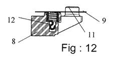
有利には、この可撓性の接触帯または各々の可撓性の接触帯9が、接触保持パネル3、4のフレーム要素8の内面に、前記内面が備えるつめ11への突き刺しによって固定される(図10〜12)。
Advantageously, this flexible contact band or each
本発明の別の有利な構成によれば、ケース1内に位置決めされるセル2の+電極および−電極と、接触帯9とは、次のように構成される。
前記セルの並列接続
または前記セルの直列接続
または前記セルの直列および並列接続
According to another advantageous configuration of the invention, the + and − electrodes of the
Parallel connection of the cells or Series connection of the cells or Series and parallel connection of the cells
ケース1に位置決めされるセル2は、複数の平行な列または行を形成し、それらの軸は、一定の距離またはピッチpにより隔てられ、本発明の特徴的な構成によれば、一方の接触保持パネルの可撓性の接触帯9’は、他方の接触保持パネルの接触帯9”に対してピッチpだけオフセットされている(図14)。
The
非常に有効な実施形態によれば、パネル3と4のフレーム要素の内面が、セル2の+または−の端子に向かって配向された複数のばねを備えており、これらのばねが、接触帯9の可撓性ブレード10に当接されることによって、前記端子に前記可撓性ブレード10を個々に当接可能にしている。
According to a very effective embodiment, the inner surfaces of the frame elements of the
これらのばねは、好適にはパネル3と4のフレーム要素8に、それらの一端を介して分解不能に固定されたコイルばね12から構成される(図12)。
These springs are preferably composed of
前述のように、接触保持パネル3、4は、ねじ5を用いて、中央の位置決めセパレータ1に組み立てられる。この組立を可能にするねじ留め用のねじの一部分は、接触帯9の間に設けられたスペース13を通る。ねじ5は、ケースにより画定されるスペースの内部で、ケース1がその周辺部に有する柱状部15にねじ留めされる。柱状部15は、ケースの高さよりもやや高いので、ケース1の各面から突出している。
As described above, the
有利には、接触帯9の間に設けられたスペース13を通るねじ5は、それらのねじ留め軸がケース1に位置決めされた4個のばね群12a、12b、12c、12dの軸と4個のセル2a、2b、2c、2dまたは2a’、2b’、2c’、2d’群の軸との中心にくるように配分される(図13)。このような多数の組立箇所と、それらの配分とを検討することにより、電池パックの3つの部分を堅牢に組み立てることができ、また、セル2からなるアセンブリの+と−の電極または端子に可撓性の接触ブレード10の全体を一定かつ安定して当接させることができる。
Advantageously, the
相互接続帯9のブレード10と、セル2の+と−の電極とが、このように直接安定して接触することによって、前記セルの電圧を非常に正確に測定可能になる。その理由は、このような接触によって抵抗をごく小さくすることができ、特にリチウムイオン電池の場合に必要な測定を誤らせることがないからである。
This direct and stable contact between the
有利には、セル2の+と−の電極と、相互接続帯9の可撓性ブレード10との接触面が、それ自体公知の導電性接点グリースにより被覆される。
Advantageously, the contact surfaces of the + and-electrodes of the
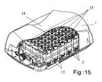
接触保持パネル3、4は、ほぼ同じものとすることができ、位置決めセパレータ1およびセル2と共に、ケーシングまたは外装14に収容可能な電池パックを構成可能である。有利には、接触保持パネル3、4は、電池のケーシングを直接構成するように配置可能であり、パネル3が、たとえばこのケーシングの底を構成し、ケーシングのカバーが、この場合にはパネル4から形成される。別の実施形態によれば、下部パネルがケーシングの底を構成し、ケーシングの残りの部分が、前記底に着脱式に固定されるカバーから形成される。
The
使用器具または充電器への電池接続を可能にする接続端子への接触帯の接続手段や、電池の適正動作および安全性を確保する電子回路については、当業者にとってよく知られているので、その説明を省く。 The means for connecting the contact zone to the connection terminal that enables battery connection to the appliance or charger used and the electronic circuit that ensures the proper operation and safety of the battery are well known to those skilled in the art. Omit the explanation.
上記のように構成された電池16の別の特徴は、この電池が携帯式であることにある。
Another feature of the
電池は、リュックサックタイプのかばん17(図15)に入れることができ、あるいは、電池16または電池パックのケーシング14の外側部分の1つが、持ち運びを可能にするベルトまたはストラップ18を備えることができる(図16)。
The battery can be placed in a rucksack type bag 17 (FIG. 15), or one of the outer portions of the
1 セパレータケース
2 セル
3、4 接触保持パネル
5 ねじ
6 貫通孔
7 通路
8 フレーム要素
9 接触帯
10 接触ブレード
11 つめ
12 コイルばね
13 スペース
14 ケージング
15 突出柱状部
16 電池
17 かばん
18 ベルト
DESCRIPTION OF
Claims (18)
A portable, said battery (16) is, in one or outer portion of the battery pack of the outer portion of the placed in Li Yukkusakku type bag (17), or the casing (14) (3,4) 1 18. A battery according to any one of the preceding claims, characterized in that it comprises a belt or strap (18) connected to one.
Applications Claiming Priority (3)
| Application Number | Priority Date | Filing Date | Title |
|---|---|---|---|
| FR0706239 | 2007-09-06 | ||
| FR0706239A FR2920913B1 (en) | 2007-09-06 | 2007-09-06 | BATTERY CONSISTING OF A PLURALITY OF CELLS POSITIONED AND CONNECTED BETWEEN THEM, WITHOUT WELDING. |
| PCT/FR2008/001224 WO2009063143A1 (en) | 2007-09-06 | 2008-09-02 | Battery consisting of a plurality of cells positioned and connected together without welding |
Publications (2)
| Publication Number | Publication Date |
|---|---|
| JP2010538435A JP2010538435A (en) | 2010-12-09 |
| JP5307140B2 true JP5307140B2 (en) | 2013-10-02 |
Family
ID=39027607
Family Applications (1)
| Application Number | Title | Priority Date | Filing Date |
|---|---|---|---|
| JP2010523557A Expired - Fee Related JP5307140B2 (en) | 2007-09-06 | 2008-09-02 | Batteries consisting of multiple cells positioned and interconnected without welding |
Country Status (19)
| Country | Link |
|---|---|
| US (1) | US8703325B2 (en) |
| EP (1) | EP2034539B1 (en) |
| JP (1) | JP5307140B2 (en) |
| KR (1) | KR101507510B1 (en) |
| CN (1) | CN101919085B (en) |
| AT (1) | ATE545965T1 (en) |
| AU (1) | AU2008322759B2 (en) |
| BR (1) | BRPI0816210A2 (en) |
| CA (1) | CA2697231C (en) |
| CY (1) | CY1112715T1 (en) |
| DK (1) | DK2034539T3 (en) |
| ES (1) | ES2382688T3 (en) |
| FR (1) | FR2920913B1 (en) |
| MX (1) | MX2010002457A (en) |
| NZ (1) | NZ584290A (en) |
| PL (1) | PL2034539T3 (en) |
| PT (1) | PT2034539E (en) |
| RU (1) | RU2477548C2 (en) |
| WO (1) | WO2009063143A1 (en) |
Families Citing this family (57)
| Publication number | Priority date | Publication date | Assignee | Title |
|---|---|---|---|---|
| KR101065926B1 (en) * | 2009-07-09 | 2011-09-19 | 삼성에스디아이 주식회사 | Secondary battery |
| US8361646B2 (en) | 2010-03-15 | 2013-01-29 | Electronvault, Inc. | Modular interconnection system |
| JP5595773B2 (en) * | 2010-03-31 | 2014-09-24 | 株式会社マキタ | Portable power bag |
| FR2959095B1 (en) | 2010-04-21 | 2013-04-26 | Pellenc Sa | PORTABLE MOTORIZED APPARATUS FOR SOIL WORKING |
| US20120244397A1 (en) * | 2010-07-12 | 2012-09-27 | Coda Automotive, Inc. | Battery assembly |
| DE102010034686A1 (en) | 2010-08-18 | 2012-02-23 | Volkswagen Ag | Contact element for interconnecting battery cells of battery unit for e.g. electric vehicle, has contact layers arranged between electrodes of cells, where elastic retainer and resilient plastic contact are provided within contact layers |
| US10020474B2 (en) * | 2011-04-12 | 2018-07-10 | Hitachi Automotive Systems, Ltd. | Cell block |
| DE102011117757A1 (en) * | 2011-11-05 | 2013-05-08 | Robert Bosch Gmbh | Soldering method for producing an electrically conductive connection |
| US9054367B2 (en) * | 2012-02-01 | 2015-06-09 | Samsung Sdi Co., Ltd. | Rechargeable battery assembly and pack including the same |
| DE102012202694B4 (en) * | 2012-02-22 | 2017-11-02 | Lisa Dräxlmaier GmbH | Module for a traction battery and traction battery |
| DE102012213273B4 (en) | 2012-07-27 | 2021-08-05 | Hydac Technology Gmbh | Energy storage device |
| JP6065339B2 (en) * | 2012-08-13 | 2017-01-25 | 日立工機株式会社 | Back load type power supply |
| CN104582907B (en) * | 2012-08-20 | 2016-09-14 | 日立工机株式会社 | Backpack type power supply |
| WO2014077386A1 (en) * | 2012-11-19 | 2014-05-22 | 日立工機株式会社 | Shouldered power supply |
| EP2744033B1 (en) * | 2012-12-07 | 2015-02-18 | Obrist Powertrain GmbH | Battery |
| JP5903564B2 (en) | 2013-12-13 | 2016-04-13 | パナソニックIpマネジメント株式会社 | Assembled battery |
| CN103682205A (en) * | 2013-12-25 | 2014-03-26 | 山东神工海特电子科技有限公司 | Novel lithium ion battery |
| KR102238556B1 (en) | 2014-02-28 | 2021-04-08 | 삼성에스디아이 주식회사 | Rechargeable battery pack |
| JP5873903B2 (en) * | 2014-08-05 | 2016-03-01 | 株式会社マキタ | Portable power bag |
| US9520587B2 (en) | 2014-09-30 | 2016-12-13 | Johnson Controls Technology Company | Bus bar assembly carrier |
| DE102014017622A1 (en) * | 2014-11-27 | 2016-06-02 | Audi Ag | Connecting element, current collecting device and associated manufacturing method |
| KR101620263B1 (en) * | 2015-02-13 | 2016-05-12 | 엘지전자 주식회사 | Vacuum cleaner, battery assembly, and charging device |
| EP3241254B1 (en) | 2015-04-16 | 2018-04-25 | Neuss, Wilhem | Battery module |
| USD763193S1 (en) | 2015-06-02 | 2016-08-09 | Johnson Controls Technology Controls | Bus bar carrier for lithium ion battery module |
| DE102015220334A1 (en) | 2015-10-19 | 2017-04-20 | Robert Bosch Gmbh | Filling device for filling battery devices with battery cells |
| US10115943B2 (en) * | 2015-11-02 | 2018-10-30 | Korea Institute Of Energy Research | Battery packing module and battery pack |
| CN105406002A (en) * | 2015-12-28 | 2016-03-16 | 天津力神特种电源科技股份公司 | Novel modularized battery pack |
| DE102016105091B4 (en) * | 2016-03-18 | 2018-05-30 | Maraneo Gmbh | Battery housing for a propulsion device for divers and swimmers |
| JP6776379B2 (en) * | 2016-06-03 | 2020-10-28 | イーセブン システムズ テクノロジー マネジメント リミテッドE−Seven Systems Technology Management Ltd | battery |
| FR3056022B1 (en) | 2016-09-13 | 2019-10-11 | Pellenc | DEVICE FOR ELECTRICALLY INTERCONNECTING BATTERY ELEMENTS AND BATTERY OF BATTERIES PROVIDED WITH SUCH A DEVICE |
| TWI613856B (en) * | 2016-11-08 | 2018-02-01 | Solderless cylindrical battery pack device | |
| WO2018215725A1 (en) * | 2017-05-23 | 2018-11-29 | Aceleron Limited | Battery pack assembly |
| JP6798432B2 (en) * | 2017-06-20 | 2020-12-09 | トヨタ自動車株式会社 | How to manufacture assembled batteries, battery modules and assembled batteries |
| CN107331817A (en) * | 2017-07-27 | 2017-11-07 | 深圳市尚石脉智能科技有限公司 | Lithium battery structure |
| DE102017213470A1 (en) * | 2017-08-03 | 2019-02-07 | Bayerische Motoren Werke Aktiengesellschaft | Battery module and battery module stack for a motor vehicle |
| FR3073671B1 (en) | 2017-11-15 | 2021-11-12 | Pymco Tech | ENERGY BLOCK CONSISTING OF A SEAMLESS ASSEMBLY OF A PLURALITY OF BATTERY CELLS |
| WO2020074790A1 (en) | 2018-10-09 | 2020-04-16 | Tyva Energie | Electric battery |
| US20220102812A1 (en) * | 2019-01-29 | 2022-03-31 | Narrabundah Technology Holdings Pty Ltd | Battery pack |
| WO2020156644A1 (en) * | 2019-01-29 | 2020-08-06 | Skopos Limited | Modular battery system with parallel cell cooling |
| WO2020164692A1 (en) * | 2019-02-12 | 2020-08-20 | Hpf Gmbh | Storage battery module and stored energy source |
| DE102019107993B4 (en) * | 2019-03-28 | 2021-04-15 | Webasto SE | Device for contacting a first battery unit with a second battery unit, and battery arrangement |
| KR20210026486A (en) * | 2019-08-30 | 2021-03-10 | 주식회사 엘지화학 | Apparatus for charging and discharging secondary battery |
| CN110854322A (en) * | 2019-09-20 | 2020-02-28 | 杭州乾代科技有限公司 | Modularized lithium battery module |
| CA3152746A1 (en) | 2019-09-30 | 2021-04-08 | Tanner OBER | Apparatus and method for connecting electrical components |
| US11605860B2 (en) | 2020-10-11 | 2023-03-14 | Advanced Powering Services, Inc. | Battery pack |
| EP4241327A1 (en) * | 2020-11-03 | 2023-09-13 | Exicom Tele-Systems Limited | Cell retainer assembly and method thereof |
| CN112388274A (en) * | 2020-11-20 | 2021-02-23 | 深圳市金凯博自动化测试有限公司 | Distance changing mechanism for disassembling battery core |
| WO2022189866A1 (en) * | 2021-03-11 | 2022-09-15 | Chopra, Grisha | A solder less battery pack |
| WO2022195605A1 (en) * | 2021-03-16 | 2022-09-22 | Praveen Bhaskar Reddi | Swappable modular battery pack and assembly thereof |
| FR3130457A1 (en) | 2021-12-13 | 2023-06-16 | Powzl | ELECTRIC GENERATOR COMPRISING A PLURALITY OF BATTERIES |
| DE102022202710A1 (en) | 2022-03-19 | 2023-09-21 | Theo Seiler | Storage device for receiving and dispensing at least two energy storage devices and wheel body energy storage structures for use in such a storage device |
| LU501693B1 (en) | 2022-03-19 | 2023-09-22 | Theo Seiler | Storage device for receiving and dispensing at least two energy storage devices and wheel body energy storage structures for use in such a storage device |
| WO2024000071A1 (en) * | 2022-06-28 | 2024-01-04 | Litens Automotive Partnership | Cell biasing methods for a battery |
| FR3137794A1 (en) * | 2022-07-05 | 2024-01-12 | Capacite | SOLUTION FOR PREHEATING AN ELECTRIC VEHICLE BATTERY |
| KR20240047580A (en) * | 2022-10-05 | 2024-04-12 | 주식회사 엘지에너지솔루션 | Welding-free battery module |
| WO2024075039A1 (en) * | 2022-10-06 | 2024-04-11 | Hyba Ltd. | Battery module of the type that can be disassembled and battery pack obtained assembling at least two such battery modules |
| CN116759737B (en) * | 2023-08-16 | 2023-11-14 | 中宏科创新能源科技(浙江)有限公司 | Battery module bundling assembly and battery module |
Family Cites Families (21)
| Publication number | Priority date | Publication date | Assignee | Title |
|---|---|---|---|---|
| DE515051C (en) * | 1929-07-27 | 1931-01-06 | Karl Langer | Connection contact of electrical elements to a battery |
| GB359441A (en) * | 1930-07-21 | 1931-10-21 | John William Manley | Improvements in electric batteries |
| JPS56149766A (en) * | 1980-04-19 | 1981-11-19 | Hitachi Maxell Ltd | Cylindrical alkaline battery |
| FR2578103B1 (en) | 1985-02-27 | 1987-05-15 | Bernier Ets | BATTERY BOX, ESPECIALLY FOR MILITARY USE |
| JPH0768663B2 (en) * | 1987-08-25 | 1995-07-26 | 東洋紡績株式会社 | Surface material for sanitary goods |
| JPH01232657A (en) * | 1988-03-11 | 1989-09-18 | Fuji Elelctrochem Co Ltd | Layer built cell |
| US5104754A (en) * | 1990-10-05 | 1992-04-14 | Motorola, Inc. | Weldless battery pack |
| US5096788A (en) | 1990-10-05 | 1992-03-17 | Motorola, Inc. | Weldless battery pack |
| DE4110984C2 (en) | 1991-04-05 | 1995-01-05 | Abb Patent Gmbh | Battery case |
| US5169733A (en) * | 1991-07-08 | 1992-12-08 | Motorola, Inc. | Shock absorbing battery cell interconnect |
| US5225292A (en) * | 1992-01-16 | 1993-07-06 | Globe-Union Inc. | Internally folded expanded metal electrode for battery construction |
| US5711988A (en) * | 1992-09-18 | 1998-01-27 | Pinnacle Research Institute, Inc. | Energy storage device and its methods of manufacture |
| RU2187865C2 (en) * | 1997-01-13 | 2002-08-20 | Овоник Бэттери Компани, Инк. | Mechanical and thermal perfection of nickel-cadmium-hybrid batteries, battery modules and blocks of batteries |
| JP3698296B2 (en) * | 1999-08-19 | 2005-09-21 | 株式会社マキタ | Terminal structure |
| JP4665277B2 (en) * | 1999-11-30 | 2011-04-06 | ソニー株式会社 | Battery device |
| DE10064648C2 (en) * | 1999-12-28 | 2003-09-18 | Honda Motor Co Ltd | battery unit |
| JP5049436B2 (en) * | 2001-09-28 | 2012-10-17 | パナソニック株式会社 | Assembled battery |
| JP3848565B2 (en) * | 2001-11-27 | 2006-11-22 | 松下電器産業株式会社 | Battery connection structure, battery module, and battery pack |
| US7029787B2 (en) * | 2002-03-05 | 2006-04-18 | Honda Giken Kogyo Kabushiki Kaisha | Power supply unit |
| RU2230403C1 (en) * | 2002-10-11 | 2004-06-10 | Груздев Александр Иванович | Electrical accumulator battery |
| JP4127501B2 (en) * | 2002-11-19 | 2008-07-30 | 松下電器産業株式会社 | Battery connection structure, battery module, and battery pack |
-
2007
- 2007-09-06 FR FR0706239A patent/FR2920913B1/en not_active Expired - Fee Related
-
2008
- 2008-09-02 KR KR1020107007339A patent/KR101507510B1/en active IP Right Grant
- 2008-09-02 ES ES08358010T patent/ES2382688T3/en active Active
- 2008-09-02 NZ NZ584290A patent/NZ584290A/en not_active IP Right Cessation
- 2008-09-02 US US12/673,014 patent/US8703325B2/en active Active
- 2008-09-02 PL PL08358010T patent/PL2034539T3/en unknown
- 2008-09-02 CA CA2697231A patent/CA2697231C/en not_active Expired - Fee Related
- 2008-09-02 RU RU2010112998/07A patent/RU2477548C2/en not_active IP Right Cessation
- 2008-09-02 PT PT08358010T patent/PT2034539E/en unknown
- 2008-09-02 AU AU2008322759A patent/AU2008322759B2/en not_active Ceased
- 2008-09-02 EP EP20080358010 patent/EP2034539B1/en active Active
- 2008-09-02 BR BRPI0816210-7A patent/BRPI0816210A2/en not_active IP Right Cessation
- 2008-09-02 AT AT08358010T patent/ATE545965T1/en active
- 2008-09-02 CN CN200880105959.4A patent/CN101919085B/en active Active
- 2008-09-02 WO PCT/FR2008/001224 patent/WO2009063143A1/en active Application Filing
- 2008-09-02 JP JP2010523557A patent/JP5307140B2/en not_active Expired - Fee Related
- 2008-09-02 DK DK08358010T patent/DK2034539T3/en active
- 2008-09-02 MX MX2010002457A patent/MX2010002457A/en active IP Right Grant
-
2012
- 2012-05-04 CY CY20121100416T patent/CY1112715T1/en unknown
Also Published As
| Publication number | Publication date |
|---|---|
| AU2008322759B2 (en) | 2013-04-11 |
| CA2697231C (en) | 2015-10-27 |
| CY1112715T1 (en) | 2016-02-10 |
| AU2008322759A1 (en) | 2009-05-22 |
| BRPI0816210A2 (en) | 2015-06-16 |
| CN101919085B (en) | 2014-09-10 |
| NZ584290A (en) | 2012-09-28 |
| ATE545965T1 (en) | 2012-03-15 |
| RU2477548C2 (en) | 2013-03-10 |
| US8703325B2 (en) | 2014-04-22 |
| WO2009063143A1 (en) | 2009-05-22 |
| JP2010538435A (en) | 2010-12-09 |
| CN101919085A (en) | 2010-12-15 |
| EP2034539B1 (en) | 2012-02-15 |
| ES2382688T3 (en) | 2012-06-12 |
| KR20100071055A (en) | 2010-06-28 |
| US20110177373A1 (en) | 2011-07-21 |
| PL2034539T3 (en) | 2012-07-31 |
| MX2010002457A (en) | 2010-06-23 |
| DK2034539T3 (en) | 2012-05-29 |
| CA2697231A1 (en) | 2009-05-22 |
| FR2920913B1 (en) | 2009-11-13 |
| KR101507510B1 (en) | 2015-03-31 |
| PT2034539E (en) | 2012-04-13 |
| RU2010112998A (en) | 2011-10-20 |
| EP2034539A1 (en) | 2009-03-11 |
| FR2920913A1 (en) | 2009-03-13 |
Similar Documents
| Publication | Publication Date | Title |
|---|---|---|
| JP5307140B2 (en) | Batteries consisting of multiple cells positioned and interconnected without welding | |
| KR101016596B1 (en) | Cell cartridge | |
| KR102316488B1 (en) | Cylindrical cell connection separated bus bar and battery module using the same and manufacturing method | |
| KR101042750B1 (en) | Battery Pack | |
| JP6229903B2 (en) | Battery module | |
| WO2010147384A2 (en) | Instrument connection type unit pack combined cell cartridge | |
| EP2438639B1 (en) | Lithium ion battery pack having cathode and anode current collectors | |
| US20180229621A1 (en) | Battery module, battery pack comprising battery module, and vehicle comprising battery pack | |
| US20200176735A1 (en) | Battery module | |
| JP6571621B2 (en) | Battery module | |
| KR20170040638A (en) | Battery module and battery pack including the same | |
| WO2011033727A1 (en) | Assembled battery, assembled battery aggregate, and battery module | |
| KR101036060B1 (en) | Connector and Battery Pack having the same | |
| KR100943575B1 (en) | Recharbeable battery | |
| KR102050033B1 (en) | High temperature pressing device for battery cell of photovoltaic module | |
| CN109964352B (en) | Apparatus for manufacturing battery pack | |
| TWI658634B (en) | Battery module | |
| WO2017155118A1 (en) | Power source device production method and power source device | |
| CN111261823B (en) | Battery pack | |
| KR20170027547A (en) | Cell module for secondary battery pack and assembly method for the same | |
| CN110896134A (en) | Battery module | |
| KR20160028750A (en) | Battery pack | |
| KR20210100365A (en) | Cell jig, apparatus of evaluating a lithium secondary battery including the same and method of evaluating a lithium secondary battery using the cell jig |
Legal Events
| Date | Code | Title | Description |
|---|---|---|---|
| A621 | Written request for application examination |
Free format text: JAPANESE INTERMEDIATE CODE: A621 Effective date: 20110518 |
|
| A131 | Notification of reasons for refusal |
Free format text: JAPANESE INTERMEDIATE CODE: A131 Effective date: 20130128 |
|
| A601 | Written request for extension of time |
Free format text: JAPANESE INTERMEDIATE CODE: A601 Effective date: 20130426 |
|
| A602 | Written permission of extension of time |
Free format text: JAPANESE INTERMEDIATE CODE: A602 Effective date: 20130508 |
|
| A521 | Request for written amendment filed |
Free format text: JAPANESE INTERMEDIATE CODE: A523 Effective date: 20130527 |
|
| TRDD | Decision of grant or rejection written | ||
| A01 | Written decision to grant a patent or to grant a registration (utility model) |
Free format text: JAPANESE INTERMEDIATE CODE: A01 Effective date: 20130618 |
|
| A61 | First payment of annual fees (during grant procedure) |
Free format text: JAPANESE INTERMEDIATE CODE: A61 Effective date: 20130626 |
|
| R150 | Certificate of patent or registration of utility model |
Free format text: JAPANESE INTERMEDIATE CODE: R150 Ref document number: 5307140 Country of ref document: JP Free format text: JAPANESE INTERMEDIATE CODE: R150 |
|
| R250 | Receipt of annual fees |
Free format text: JAPANESE INTERMEDIATE CODE: R250 |
|
| R250 | Receipt of annual fees |
Free format text: JAPANESE INTERMEDIATE CODE: R250 |
|
| R250 | Receipt of annual fees |
Free format text: JAPANESE INTERMEDIATE CODE: R250 |
|
| R250 | Receipt of annual fees |
Free format text: JAPANESE INTERMEDIATE CODE: R250 |
|
| R250 | Receipt of annual fees |
Free format text: JAPANESE INTERMEDIATE CODE: R250 |
|
| LAPS | Cancellation because of no payment of annual fees |