JP5286920B2 - Vehicle seat device - Google Patents
Vehicle seat device Download PDFInfo
- Publication number
- JP5286920B2 JP5286920B2 JP2008121749A JP2008121749A JP5286920B2 JP 5286920 B2 JP5286920 B2 JP 5286920B2 JP 2008121749 A JP2008121749 A JP 2008121749A JP 2008121749 A JP2008121749 A JP 2008121749A JP 5286920 B2 JP5286920 B2 JP 5286920B2
- Authority
- JP
- Japan
- Prior art keywords
- seat
- vehicle
- seat back
- door
- lock
- Prior art date
- Legal status (The legal status is an assumption and is not a legal conclusion. Google has not performed a legal analysis and makes no representation as to the accuracy of the status listed.)
- Expired - Fee Related
Links
Images


Description
この発明は、車室の底面を形成するフロアパネルと、該フロアパネルの車外側に設けられた乗降用開口と、この乗降用開口を開閉自在に覆うサイドドアとを備え、該サイドドアの側部に乗員が着座可能なシートが設けられたような車両のシート装置に関する。 The present invention includes a floor panel that forms a bottom surface of a passenger compartment, a boarding / alighting opening provided on the vehicle exterior side of the floor panel, and a side door that covers the boarding / opening door so as to be openable and closable. The present invention relates to a vehicle seat device in which a seat on which a passenger can be seated is provided.
近年、車両に対してスキー板やサーフボードその他の長尺物を搭載するという要求があり、斯る要求に対応して長尺物を有効に積載する車両のシート装置が既に発明されている(特許文献1〜3参照)。 In recent years, there has been a demand to mount skis, surfboards, and other long objects on vehicles, and vehicle seat devices that effectively load long objects in response to such requests have already been invented (patents). References 1-3).
特許文献1に開示された車両のシート装置は、フロアパネルの後部にフロント側の段差部を介してリヤシートパンを設け、このリヤシートパンの後部にリヤ側の段差部を介して荷室フロアを設ける一方、フロアパネル上にはシートクッションとシートバックとを備えたフロントシートを配設し、リヤシートパン上にはシートクッションとシートバックとを備えたリヤシートを配設したものであって、通常の着座状態から、まず、リヤシートのシートクッションを前方へ反転回動させて、該シートクッションをフロアパネル上に位置させた後に、リヤシートのシートバックを前方へ倒して、該シートバックをリヤシートパン上に位置させ、次にフロントシートのシートバックを後方へ回動させて、このシートバックを反転回動させたリヤシートのシートクッション上に位置させると、フロントシートのシートクッション、フロントシートのシートバック、リヤシートのシートバックおよび荷室フロアが前後方向に略連続して、この連続した荷室面に長尺の荷物を搭載することができる。
The vehicle seat device disclosed in
特許文献2に開示された車両のシート装置は、リヤシートパン上に、シートクッションとシートバックとを備えたリヤシートを配設し、長尺の荷物を搭載する場合には、上述のシートバックをシートクッション上に前倒しして、このシートバックの背面と荷室フロアの荷室面とを前後方向に連続させて、この連続した荷室面に長尺の荷物を搭載するものである(特許文献2の図8参照)。
In a vehicle seat device disclosed in
特許文献3に開示された車両のシート装置は、助手席のシートクッションと助手席のシートバックとが略同一平面内にて連続するように、まず該助手席のシートバックを後方に傾け、この状態の助手席を運転席側に向くように跳ね上げて起立させる一方、助手席後方のリヤシートのシートバックをそのシートクッション上に前倒しして、車室後端助手席側から車室前端助手席側へ至る空間を形成し、この空間に対して車室の全長にわたる長尺の荷物を搭載するように構成したものである。
The vehicle seat device disclosed in
このように、上記各特許文献1〜3に開示された従来構造によれば、シートアレンジにより、それぞれ長尺の荷物を搭載することができるという利点がある一方、これらの各特許文献1〜3においては、シートバックの前方移動により、外部からアクセスしにくく、人目につき難い荷室空間(セキュリティボックス空間)を形成するという技術思想は開示されていない。
そこで、この発明は乗降用開口を覆うサイドドアの側部に乗員が着座可能なシートが設けられ、該シートは座面を形成するシートクッションと、このシートクッションの後部から上方に延びて背もたれ面を形成するシートバックとを備え、シートバックが前方に移動して、上記シートクッションとサイドドアの側面と協同して荷物を収納可能な荷室空間を形成すべく構成することで、外部からアクセスしにくく、人目につき難い荷室空間(セキュリティボックス空間)を簡単に形成することができ、その荷室空間に収納した物品の盗難防止性を確保することができて、収納性確保と盗難防止性確保との両立を図ることができる車両のシート装置の提供を目的とする。 Therefore, the present invention is provided with a seat on which the occupant can sit on the side portion of the side door that covers the entrance for getting on and off, and the seat includes a seat cushion that forms a seating surface, and a backrest surface that extends upward from the rear portion of the seat cushion. The seat back moves forward and cooperates with the seat cushion and the side of the side door to form a luggage space that can store luggage, thereby allowing access from the outside. It is possible to easily form a cargo space (security box space) that is difficult to see and easily noticeable, and to ensure the anti-theft property of articles stored in the cargo space, ensuring storage and anti-theft It is an object of the present invention to provide a vehicle seat device that can achieve both ensuring and ensuring.
この発明による車両のシート装置は、車室の底面を形成するフロアパネルと、該フロアパネルの車外側に設けられた乗降用開口と、該乗降用開口を開閉自在に覆うサイドドアと、を備え、上記サイドドアの側部に乗員が着座可能なシートが設けられた車両のシート装置であって、上記シートは、座面を形成するシートクッションと、該シートクッションの後部から上方に延びて背もたれ面を形成するシートバックと、を備え、上記シートバックが前方に移動し上記シートクッションと上記サイドドアの側面と協同して荷物を収納可能な荷室空間を形成するように構成し、上記サイドドアには、上記シートバックの前傾状態をロックするロック機構が設けられ、上記ロック機構は、上記サイドドアの開閉に連動して作動するものである。
上記構成によれば、シートバックを前方に移動させると、このシートバックと、シートクッションと、サイドドアの側面と協同して荷物を収納可能な荷室空間(セキュリティボックス空間)が形成でき、該荷室空間の上方部は上記シートバックで覆われる。
A vehicle seat device according to the present invention includes a floor panel that forms a bottom surface of a passenger compartment, a boarding / alighting opening provided on the vehicle exterior side of the floor panel, and a side door that covers the boarding / alighting opening so as to be freely opened and closed. A seat device for a vehicle in which a seat on which a passenger can be seated is provided on a side portion of the side door, wherein the seat includes a seat cushion that forms a seating surface, and a backrest that extends upward from a rear portion of the seat cushion. A seat back that forms a surface, wherein the seat back moves forward and cooperates with the seat cushion and the side surface of the side door to form a luggage space that can store luggage, and the side The door is provided with a lock mechanism that locks the forward tilted state of the seat back, and the lock mechanism operates in conjunction with opening and closing of the side door .
According to the above configuration, when the seat back is moved forward, a luggage compartment space (security box space) capable of storing luggage can be formed in cooperation with the seat back, the seat cushion, and the side surface of the side door, The upper part of the cargo space is covered with the seat back.
このため、外部からアクセスしにくく、人目につき難い荷室空間(セキュリティボックス空間)を簡単に形成することができ、また、該荷室空間に収納した小物などの物品の盗難防止性(いわゆる防盗性)を確保することができる。要するに、収納性確保と盗難防止性確保との両立を図ることができる。
また、上記荷室空間は小物入れ空間として適切なものであって、この小物入れ空間の簡易な形成と、使用時の見栄え確保と、の両立を図ることができる。
For this reason, it is possible to easily form a luggage space (security box space) that is difficult to access from the outside and is difficult to see, and the antitheft property of articles such as small articles stored in the luggage space (so-called anti-theft property). ) Can be secured. In short, it is possible to achieve both the secure storage and the anti-theft security.
The luggage space is suitable as an accessory space, and it is possible to achieve both the simple formation of the accessory space and the securing of appearance during use.
しかも、上記サイドドアには、上記シートバックの前傾状態をロックするロック機構が設けられたものであるから、該ロック機構によりサイドドアの剛性向上を図ることができると共に、前傾状態のシートバックをロックすることができるので、盗難防止性の向上と車体剛性の向上とを両立させることができる。 In addition, since the side door is provided with a locking mechanism that locks the forward tilted state of the seat back, the locking mechanism can improve the rigidity of the side door and the forward tilted seat. Since the back can be locked, it is possible to improve both the anti-theft property and the rigidity of the vehicle body.
さらに、上記ロック機構は、上記サイドドアの開閉に連動して作動するものであり、このように、サイドドアの開閉に連動してロック機構が作動するので、乗員の乗降を妨げることなく、ロック機構によるロック、アンロックを行なうことができる。 Further, the lock mechanism is state, and are not operated in conjunction with the opening and closing of the side door, thus, the lock mechanism in conjunction with the opening and closing of the side door is operated, without interfering with the occupant of the passenger, Locking and unlocking can be performed by a locking mechanism.
この発明の一実施態様においては、上記シートバックは、その中間部に上記シートクッションと所定の距離を確保して前傾可能と成す中折れ部を備えたものである。
上記構成によれば、シートバックの中折れ構造により、荷室空間(セキュリティボックス空間)の容積拡大を図ることができる。
In one embodiment of the present invention, the seat back is provided with a middle bent portion at a middle portion thereof that can be tilted forward while ensuring a predetermined distance from the seat cushion.
According to the said structure, the volume expansion of cargo space (security box space) can be aimed at by the folding structure of a seat back.
この発明の一実施態様においては、上記フロアパネルの車幅方向中央部には、車室内側へ突出したトンネル部が設けられ、上記シートバックはその背面が上記トンネル部と略同一高さとなるように前傾可能に設けられたものである。
上記構成によれば、前傾時のシートバック背面とトンネル部とが略同一高さとなるので、荷室空間(セキュリティボックス空間)を略完全な密閉空間と成すことができて、盗難防止性の向上を図ることができる。
In one embodiment of the present invention, a tunnel portion that protrudes toward the vehicle interior side is provided at the vehicle width direction center portion of the floor panel, and the back surface of the seat back is substantially flush with the tunnel portion. It is provided so that it can be tilted forward.
According to the above configuration, since the back of the seat back and the tunnel portion when tilted forward are substantially the same height, the cargo space (security box space) can be formed as a substantially complete sealed space, and the anti-theft property can be achieved. Improvements can be made.
この発明の一実施態様においては、上記シートは、そのシートクッションが前方起立状態に移動可能に設けられ、上記ロック機構は、上記シートバックの前傾状態をロックするシートバックロック用と、上記シートクッションの前方起立状態をロックするシートクッションロック用との複数を備えたものである。
上記構成によれば、複数のロック機構でシートバック、シートクッションをロックするので、盗難防止性のさらなる向上を図ることができ、また、シートクッションを前方起立状態に移動させることができるので、シートクッションが通常着座状態から前方起立状態へ移動した分、荷室空間の容積拡大を図ることができ、しかも、複数のロック機構により車体剛性の向上を図ることができる。
In one embodiment of the present invention, the seat is provided such that a seat cushion thereof is movable in a forward standing state, and the locking mechanism includes a seat back lock for locking a forward tilt state of the seat back, and the seat. It is provided with a plurality of seat cushion locks that lock the front standing state of the cushion.
According to the above configuration, since the seat back and the seat cushion are locked by the plurality of lock mechanisms, the anti-theft performance can be further improved, and the seat cushion can be moved to the front standing state. The volume of the cargo space can be increased by the amount of movement of the cushion from the normal seating state to the front standing state, and the vehicle body rigidity can be improved by a plurality of lock mechanisms.
この発明の一実施態様においては、上記シートは車幅方向に並んで一対設けられたものである。
上記構成によれば、一対のシートを並設したことにより、荷室空間(セキュリティボックス空間)を増大させることができ、また、一対のシートに形成される荷室空間を使い分けて使用することができるので、利便性の向上を図ることができる。
In one embodiment of the present invention, a pair of the seats are provided side by side in the vehicle width direction.
According to the above configuration, by arranging the pair of sheets in parallel, the cargo space (security box space) can be increased, and the cargo space formed on the pair of sheets can be used properly. since it, Ru can enhance the convenience.
この発明によれば、乗降用開口を覆うサイドドアの側部に乗員が着座可能なシートが設けられ、該シートは座面を形成するシートクッションと、このシートクッションの後部から上方に延びて背もたれ面を形成するシートバックとを備え、シートバックが前方に移動して、上記シートクッションとサイドドアの側面と協同して荷物を収納可能な荷室空間を形成すべく構成したので、外部からアクセスしにくく、人目につき難い荷室空間(セキュリティボックス空間)を簡単に形成することができ、その荷室空間に収納した物品の盗難防止性を確保することができて、収納性確保と盗難防止性確保との両立を図ることができる効果がある。
しかも、上記サイドドアには、上記シートバックの前傾状態をロックするロック機構が設けられたものであるから、該ロック機構によりサイドドアの剛性向上を図ることができると共に、前傾状態のシートバックをロックすることができるので、盗難防止性の向上と車体剛性の向上とを両立させることができる効果がある。
According to the present invention, the seat on which the occupant can sit is provided on the side portion of the side door that covers the entrance for getting on and off, and the seat extends upward from the rear portion of the seat cushion and the backrest that forms the seat surface. A seat back that forms a surface, and the seat back moves forward and cooperates with the seat cushion and the side surface of the side door to form a luggage compartment space that can store luggage. It is possible to easily form a cargo space (security box space) that is difficult to see and easily noticeable, and to ensure the anti-theft property of articles stored in the cargo space, ensuring storage and anti-theft There is an effect that it is possible to achieve a balance with ensuring.
In addition, since the side door is provided with a locking mechanism that locks the forward tilted state of the seat back, the locking mechanism can improve the rigidity of the side door and the forward tilted seat. Since the back can be locked, there is an effect that it is possible to achieve both improvement of the anti-theft property and improvement of the rigidity of the vehicle body.
さらに、上記ロック機構は、上記サイドドアの開閉に連動して作動するものであり、このように、サイドドアの開閉に連動してロック機構が作動するので、乗員の乗降を妨げることなく、ロック機構によるロック、アンロックを行なうことができる効果がある。Further, the locking mechanism operates in conjunction with the opening and closing of the side door, and thus the locking mechanism operates in conjunction with the opening and closing of the side door, thus preventing the passenger from getting on and off. There is an effect that can be locked and unlocked by the mechanism.
外部からのアクセスが困難な荷室空間(セキュリティボックス空間)の形成と、該荷室空間に収納した物品の盗難防止性確保と、を両立し、しかも、ロック機構によりサイドドアの剛性向上を図ることができると共に、前傾状態のシートバックをロックして、盗難防止性の向上と車体剛性の向上とを両立させることができるという目的を、車室の底面を形成するフロアパネルと、該フロアパネルの車外側に設けられた乗降用開口と、該乗降用開口を開閉自在に覆うサイドドアと、を備え、上記サイドドアの側部に乗員が着座可能なシートが設けられた車両のシート装置において、上記シートは、座面を形成するシートクッションと、該シートクッションの後部から上方に延びて背もたれ面を形成するシートバックと、を備え、上記シートバックが前方に移動し上記シートクッションと上記サイドドアの側面と協同して荷物を収納可能な荷室空間を形成すべく構成し、上記サイドドアには、上記シートバックの前傾状態をロックするロック機構を設け、上記ロック機構は、上記サイドドアの開閉に連動して作動するという構造にて実現した。 Both the formation of a cargo space (security box space) that is difficult to access from the outside and the prevention of theft of articles stored in the cargo space are achieved, and the locking mechanism improves the rigidity of the side door. And a floor panel that forms the bottom surface of the passenger compartment, and the floor can be locked to the forwardly tilted seat back so that both the anti-theft performance and the vehicle body rigidity can be improved. A vehicle seat apparatus comprising: a boarding opening provided on the vehicle exterior side of the panel; and a side door that covers the boarding opening so as to be freely opened and closed, and a seat on which a passenger can be seated is provided on a side portion of the side door. The seat includes: a seat cushion that forms a seat surface; and a seat back that extends upward from a rear portion of the seat cushion to form a backrest surface. Is configured to form a cargo space that can store luggage in cooperation with the seat cushion and the side surface of the side door, and the side door has a lock that locks the forward tilted state of the seat back. A mechanism is provided , and the lock mechanism is realized by a structure that operates in conjunction with opening and closing of the side door .
この発明の一実施例を以下図面に基づいて詳述する。
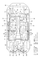
図面は、車両のシート装置を示すが、まず、図1、図2、図3を参照して車両の全体構造について説明する。ここで、図1は車両の側面図、図2は車両の平面図、図3は車両の正面図である。
An embodiment of the present invention will be described in detail with reference to the drawings.
The drawings show a vehicle seat device. First, the overall structure of the vehicle will be described with reference to FIGS. 1, 2, and 3. Here, FIG. 1 is a side view of the vehicle, FIG. 2 is a plan view of the vehicle, and FIG. 3 is a front view of the vehicle.
図1において、エンジンルーム1と車室2とを前後方向に仕切るダッシュロアパネル(ダッシュパネル)3を設け、このダッシュロアパネル3の下部には、後方に向けて略水平に延びて車室2の底面を形成するフロアパネル4を、一体または一体的に連設し、このフロアパネル4の後部には、上方に立上がるキックアップ部5およびリヤシートパン6を形成し、このリヤシートパン6にはバルクヘッド7を介してリヤフロア8(フロアパネル)を連設している。このリヤフロア8は後述する後部荷室42の底面を形成するものである。
In FIG. 1, a dash lower panel (dash panel) 3 that partitions the
上述のフロアパネル4の車幅方向中央部には、図2に平面図で示すように、車室2内に向かって突出して、車両の前後方向に延びるトンネル部9を設けている。このトンネル部9は、ダッシュロアパネル3とバルクヘッド7との間を車両の前後方向に延びており、該トンネル部9は車体剛性の中心となるものである。なお、このトンネル部9の上部には、該トンネル部9の上部に沿って前後方向に延びるトンネルメンバ(いわゆるハイマウントバックボーンフレーム)を設けてもよい。
As shown in the plan view of FIG. 2, a
また、上述のフロアパネル4の左右両サイドには、図2、図3に示すように、車両の前後方向に延びるサイドシル10を接合固定している。このサイドシル10は、サイドシルインナ11とサイドシルアウタ12とを接合して、車両の前後方向に延びるサイドシル閉断面13(図3参照)を有する車体剛性部材である。なお、上記サイドシルインナ11とサイドシルアウタ12との間には必要に応じて、サイドシルレインフォースメントを介設してもよい。
Further, as shown in FIGS. 2 and 3,
さらに、図1、図2に示すように、ダッシュロアパネル3とキックアップ部5との前後方向中間部において、上述のフロアパネル4上には、トンネル部9の縦壁とサイドシルインナ11との間を車幅方向に連結する左右のフロアクロスメンバ14,14を設け、このフロアクロスメンバ14とフロアパネル4との間には、車幅方向に延びる閉断面15を形成している。
Further, as shown in FIGS. 1 and 2, in the middle portion in the front-rear direction between the dash
図2に示すように、上述のトンネル部9とサイドシル10との間の車幅方向の中間部において、フロアパネル4の下部には、車両の前後方向に延びる左右一対のフロアフレーム16,16を接合固定して、このフロアフレーム16とフロアパネル4との間には、前後方向に延びる閉断面16a(図3参照)を形成している。
As shown in FIG. 2, a pair of left and right floor frames 16, 16 extending in the front-rear direction of the vehicle are provided at the lower portion of the
また、リヤフロア8の下部両サイドには、図1、図2に示すように、車両の前後方向に延びる左右一対のリヤサイドフレーム17,17を接合固定して、このリヤサイドフレーム17とリヤフロア8との間には、前後方向に延びる閉断面を形成すると共に、これら一対のリヤサイドフレーム17,17の前部を、サイドシル10の後部と車両前後方向にオーバラップする位置まで延設させている。
Further, as shown in FIGS. 1 and 2, a pair of left and right rear side frames 17 and 17 extending in the front-rear direction of the vehicle are joined and fixed to both lower sides of the
一方、エンジンルーム1の左右両サイドを車両の前後方向に延びるフロントフレームとしての一対のフロントサイドフレーム18,18を設けている。これらフロントサイドフレーム18,18は図1に示すように、その後部がダッシュロアパネル3の前面に沿って下方に延び、該フロントサイドフレーム18の後端部は上述のフロアフレーム16の前端部に連結されていて、このフロントサイドフレーム18とフロアフレーム16とは、図2に示すように、平面視で車両の前後方向に略一直線状に連続するものである。
On the other hand, a pair of front side frames 18 and 18 are provided as front frames extending in the longitudinal direction of the vehicle on both the left and right sides of the
また、左右一対のフロントサイドフレーム18,18間には、車幅方向に延びる閉断面構造のフロントクロスメンバ19(いわゆるNo.1.5クロスメンバ)を設ける一方、一対のフロントサイドフレーム18,18の前方には、クラッシュカン20,20(衝撃エネルギ吸収部材)を介して、車幅方向に延びるバンパレイン21(詳しくは、フロントバンパレインフォースメント)を設けている。
このバンパレイン21の車幅方向中間部には後方に後退する中間後退部21Aを形成すると共に、バンパレイン21の両端部にも後方に後退するサイド後退部21B,21Cを形成し、該バンパレイン21の平面から見た全体形状をW字状と成している。そして、このバンパレイン21の中間後退部21Aと上述のフロントクロスメンバ19との間を、クラッシュカン22(衝撃エネルギ吸収部材)で連結している。
Further, a front cross member 19 (so-called No. 1.5 cross member) having a closed cross-sectional structure extending in the vehicle width direction is provided between the pair of left and right front side frames 18, 18, while the pair of front side frames 18, 18 are provided. A bumper rain 21 (specifically, a front bumper reinforcement) extending in the vehicle width direction is provided in front of the vehicle via the
An intermediate receding
図1に示すように、上述のフロントクロスメンバ19の近傍において、左右一対のフロントサイドフレーム18,18間には、後部にファン23を備えたラジエータ24を配設している。ここで、上述のラジエータ24とファン23とは一体化されて、ラジエータユニットを構成している。またこのラジエータ24は、次に述べるエンジン25の前方に配設されたものである。
As shown in FIG. 1, in the vicinity of the
ところで、図1、図2に示すように、エンジンルーム1内の後部およびトンネル部9の車外側には、エンジン25(縦置きエンジン)とトランスミッション26とから成るパワートレイン27を配設し、エンジン25を可及的車両中心部に後退配置して所謂フロント・ミッドシップ・エンジン車と成している。
As shown in FIGS. 1 and 2, a
また、上述のトンネル部9の車外側には、トランスミッション26の出力を、リヤディファレンシャル装置28に伝達するプロペラシャフト29を設け、上述のリヤディファレンシャル装置28の差動出力を左右のドライブシャフト30,30を介して左右の後輪31,31に伝達すべく構成して、FR(前部機関後輪駆動)タイプの車両と成している。
Further, a
一方、この車両は、図1に示すように、車両前方から後方に傾斜して延びるフロントノーズ部32と、このフロントノーズ部32と連続して後方に延びて車体前方外面を形成する中間ノーズ部33と、この中間ノーズ部33の後方に設けられた車室2の前方を車外が視認可能となるように覆ったフロントウインドパネル(フロントウインドガラスと同意、以下単にフロントウインドと略記する)34と、を備えている。
On the other hand, as shown in FIG. 1, the vehicle includes a
上述のフロントウインド34は、左右のフロントピラー(図示せず)と、ルーフ部36の前端と、カウル部上端との間に形成されたフロントウインド開口を覆うもので、このフロントウインド34の下端部は、カウルパネル(図示せず)で支持される。
The above-described
さらに、上述のフロントノーズ部32より上方に所定間隔離間して車幅方向に延びるアッパノーズ部37を設けている。このアッパノーズ部37は、エネルギ吸収可能なEA部材(エネルギ・アブソーバ部材)としての発泡ウレタン部材38と、この発泡ウレタン部材38の外部を覆う樹脂製の外皮39とから構成されていて、上下方向にエネルギ吸収可能に設けられている。
Further, an
図3の正面図において仮想線で示すように、上述のアッパノーズ部37は、その車幅方向中央が上方に位置するなだらかな曲面形状に形成されており、このアッパノーズ部37の車幅方向両サイド部は、フロントノーズ部32を介して、左右のフロントフェンダ40,40と連続するように構成されている。
As indicated by a virtual line in the front view of FIG. 3, the
また、図1、図3に示すように、上述のフロントノーズ部32とアッパノーズ部37との間には、走行風を通過させて整流可能な整流通路41を形成している。すなわち、この実施例のアッパノーズ部37は、バンパ機能と、スポイラ機能と、歩行者保護機能と、を兼ねるように構成している。
Further, as shown in FIGS. 1 and 3, a rectifying
一方、この車両は、図1、図2に示すように、リヤフロア8上方の後部荷室42の開口を、リヤゲートウインド43を備えたリヤゲート44(開閉部材)によって開閉自在に覆うように構成しており、上述の後部荷室42は車室2内と連通していて、上述のリヤゲート44を図1に仮想線αで示すように開放することで、荷物の出し入れを容易に行なうように構成している。
On the other hand, as shown in FIGS. 1 and 2, the vehicle is configured so that the opening of the
図1〜図3において、45はステアリングホイール、46はインストルメントパネル、47はステアリングラック、48はサブフレーム、49は前輪である。
また、図3に示すように、上述のフロアパネル4の車外側左右には乗降用開口35(いわゆるドア開口部)が設けられており、この乗降用開口35を開閉自在に覆うサイドドアとしてのリヤドア50が設けられている。
1-3, 45 is a steering wheel, 46 is an instrument panel, 47 is a steering rack, 48 is a sub-frame, 49 is a front wheel.
Moreover, as shown in FIG. 3, the entrance / exit 35 (what is called a door opening part) is provided in the vehicle exterior left and right of the above-mentioned
図3に示すように、左右のリヤドア50はドアインナパネル50aと、ドアアウタパネル50bとを備えている。また、ドアインナパネル50aと、ドアアウタパネル50bとの間には、必要に応じてインパクトバーが設けられる。
As shown in FIG. 3, the left and right
次に、車両のシート装置について詳述する。
図4は図1の要部拡大側面図、図5はシートアレンジを示す側面図であって、図1〜図5に示すように、図示しないフロントドアの側部、つまり車室2内において、フロアクロスメンバ14と上下方向に対応する位置で、かつトンネル部9の左右両側部には、乗員が着座可能な一対の前列シート51,51が設けられている。
また、前列シート51,51の後方で、かつ上記リヤドア50の側部、つまり車室2内において、リヤシートパン6と対応する位置のトンネル部9の左右両側部には、乗員が着座可能な一対の後列シート52,52が設けられている。
Next, the vehicle seat device will be described in detail.
4 is an enlarged side view of the main part of FIG. 1, FIG. 5 is a side view showing the seat arrangement, and as shown in FIGS. 1 to 5, in the side portion of the front door (not shown), that is, in the
In addition, a pair of passengers can be seated on the left and right sides of the
図2に平面図で示すように、この実施例においては右ハンドル車を例示しているので、一対の前列シート51,51のうちトンネル部9を挟んで車幅方向の右側に設けられたシートが運転席シートとなり、トンネル部9を挟んで車幅方向の左側に設けられたシートが助手席シートとなる。
As shown in a plan view in FIG. 2, in this embodiment, a right-hand drive vehicle is illustrated, so that the seat provided on the right side in the vehicle width direction across the
図1、図2に示すように、これらの各前列シート51,51は、座面を形成するシートクッション51Cと、該シートクッション51Cの後部より上下方向に延びるシートバック51B,51Bとをそれぞれ備えたバッケットシート(セパレート・シート)であって、これらの各前列シート51,51は、そのリクライニング支点53(図1参照)を支点として、シートバック51Bがシートクッション51Cに対してリクライニング調整可能に構成されていて、前席乗員の着座姿勢の自由度を確保すべく構成している。
As shown in FIGS. 1 and 2, each of the front row seats 51 and 51 includes a
前列シート51,51の後方で、かつ、サイドドアとしてのリヤドア50の側部車室2側において、トンネル部9を挟んで車幅方向に一対に設けられた後列シートシート52,52は、座面を形成するシートクッション52Cと、該シートクッション52Cの後部より上下方向に延びるシートバック52Bとをそれぞれ備えたバッケットシート(セパレート・シート)であって、後列シート52のシートバック52Bは、下部に位置するシートバックロア52Lと、上部に位置してヘッドレストを兼ねる形状のシートバックアッパ52Uとを備えており、この後列シートは、リクライニング支点54(図4参照)を中心として、シートバックロア52Lとシートバックアッパ52Uとが一体的にシートクッション52Cに対してリクライニング調整可能に構成されており、後席乗員の着座姿勢の自由度を確保するように構成している。
Rear
図4に示すように、この実施例では後列シート52のシートクッション52C後端と、シートバックロア52Lの下端とは分離形成されており、上述のリクライニング支点54は、ブラケット55を介してバルクヘッド7などのボディ側に支持されている。
As shown in FIG. 4, in this embodiment, the rear end of the
図4は後席乗員の通常着座状態を示し、図5はシートアレンジによる荷室空間
X形成時の側面図であって、後列シート52のシートバック52Bは、その上下方向の中間部に上述のシートクッション52Cまたは、リヤシートパン6と所定の距離を確保して前傾可能と成す中折れ部56を備えている。
FIG. 4 shows a normal seating state of the rear seat occupant, and FIG. 5 is a side view when the luggage space X is formed by seat arrangement. The seat back 52B of the
すなわち、図4に示す通常着座状態から図5に示すように、中折れ部56を支点として、シートバックアッパ52Uを前方に移動させると、このシートバックアッパ52Uがシートクッション52C(または、リヤシートパン6)と所定の距離を確保して前傾状態に中折れするように構成している。
That is, when the seat back upper 52U is moved forward from the normal seating state shown in FIG. 4 with the folded
また、後列シート52は、そのシートクッション52Cが前部支点57を中心として、図4に示す通常着座状態から図5に示す前方起立状態に移動可能に構成されており、上述の前部支点57は、図4、図5に示すように、ブラケット58を介して、リヤシートパン6などのボディ側に支持されている。
ここで、図4、図5に示す左右一対のブラケット58,58のうちトンネル部9に近接するブラケット58を省略し、前部支点57の車幅内方側を、トンネル部9で直接支持するように構成してもよい。
Further, the
Here, of the pair of left and
図4に示す通常着座状態から図5の状態に成す場合には、まず、前部支点57を中心としてシートクッション52Cを前方起立状態に保持し、次に、中折れ部56を支点としてシートバックアッパ52Uを前方に移動させると、図5に示すように、リヤドア50の側面(つまり、ドアインナパネル50aの車室側の面)と、シートクッション52Cと、トンネル部9の側面と、協同して荷物を収納可能な荷室空間X(セキュリティボックス空間)が形成される。
When the normal seating state shown in FIG. 4 is changed to the state shown in FIG. 5, first, the
この荷室空間Xは、リヤシートパン6を底面とし、リヤドア50におけるドアインナパネル50aの車室側の面と、シートクッション52Cと、シートバックアッパ52Uと、シートバックロア52Lと、トンネル部9の側面とで囲繞された外部からアクセスしにくく、かつ、人目につき難いセキュリティボックス空間となる。
The luggage space X has a
さらに、図5に示すシートアレンジ状態をロックするために、シートバック52Bのシートバックアッパ52Uと、シートクッション52Cとの双方には同一構造、かつ、複数のロック部60,60が内設されており、これらの各ロック部60に対応して、リヤドア50側にはロックピン68が設けられていて、シートバックロック用の複数のロック部60,60およびロックピン68,68で、シートバックアッパ52Uの前傾状態をロックし、また、シートクッションロック用の複数のロック部60,60およびロックピン68,68で、シートクッション52Cの前方起立状態をロックするように構成している。
Furthermore, in order to lock the seat arrangement state shown in FIG. 5, both the seat back upper 52U of the seat back 52B and the
このロック部60およびロックピン68の構造を、図6、図7を参照して、以下に説明する。
このロック部60は、図示しないシートバックフレームまたはシートクッションフレームに固定された合成樹脂製のハウジング61と、このハウジング61に形成され、車外側(リヤドア50側)が開放する段差形状の開口部62と、この開口部62に固定され車幅方向内方が大径で車幅方向外方が小径となるテーパ孔状のガイド面63aを備えたガイド部材63と、上記開口部62の内奥に配設されガイド面63aに沿って車幅方向に移動可能な割り円錐チャック(split cone chuck)構造のロック部材64と、このロック部材64を車外側(リヤドア50側)に付勢する付勢部材としてのコイルスプリング65と、上記開口部62の最も車外側に配設された硬質ゴム製のストッパ66と、を備えている。
The structure of the
The
ここで、上述のロック部材64は、複数のスリット64aを有すると共に、スプリングリテーナ部64bを有している。
一方、リヤドア50のドアインナパネル50aにはシートバックアッパ52Uの前傾状態をロックするシートバックロック用の複数のロックピン68,68と、シートクッション52Cの前方起立状態をロックするシートクッションロック用の複数のロックピン68,68とが、車室2側に向けて突出するように固定されている。
Here, the
On the other hand, the door
図6はリヤドア50の閉時において、該リヤドア50側のロックピン68がロック部材64の内径部でチャックされた状態を示し、これにより図5に示すシートバックアッパ52Uの前傾状態と、シートクッション52Cの前方起立状態と、をロックするものである。
FIG. 6 shows a state in which the
図示しないアクチュエータによりロック部材64を車幅方向内側へ移動させると、図7に示すように、割り円錐チャック構造のロック部材64のチャック部外周がガイド部材63のガイド面63aにより拡径され、これに伴って該ロック部材64の内径部も拡径されるため、ロック部材64によるロックピン68のチャックが解除され、リヤドア50を開くことができる。
When the
図6、図7では、ロック機構としてのロックピン68を1つのみ図示しているが、このロックピン68は図5に示すシートバックアッパ52Uのロック部60,60の位置に対応して、リヤドア50に2つ設けられており、また、図5に示すシートクッション52Cのロック部60,60の位置に対応して、リヤドア50に2つに設けられており、この実施例では合計4つのロックピン68…がサイドドアとしてのリヤドア50に取付けられている。
6 and 7, only one
リヤドア50に一体的に設けられた各ロックピン68…は、リヤドア50の開閉に連動して作動するものであって、リヤドア50の閉時には、複数のロックピン68…でシートバックアッパ52Uの前傾状態、並びに、シートクッション52Cの前方起立状態をロック可能とし、リヤドア50の閉時には、そのアンロックが可能となるように構成されている。
Each
図4〜図7においては車両左側の後列シート52の構造について述べたが、車両右側の後列シート52は左側のそれと略左右対称に構成されている。なお、図6、図7において矢印Fは車両前方を示し、矢印Rは車両後方を示し、矢印INは車両内方を示す。
Although the structure of the
図6、図7で示したロック部60および、ロックピン68の構成に代えて、図8の構造を採用してもよい。
すなわち、図8に示す構造は、ガイド部材63の車外側に、ロック部材64の位置を規制する規制部63bを設ける一方、リヤドア50のドアインナパネル50aには、ロックピン68の取付け部に対応して、車室2側へ突出し、ドア剛性を向上するリブ状の膨出部50Cを一体形成し、この膨出部50Cのドア閉空間内にナット67を溶接固定している。
Instead of the configuration of the
That is, the structure shown in FIG. 8 is provided with a restricting
また、先端ピン部68aと、ネジ部68bと、基端の大径頭部68cとを一体形成した段付き形状のロックピン68を設け、上記ナット67に緩み止め用のスプリングワッシャ69を用いて、ロックピン68のネジ部68bを締付け固定し、ドアインナパネル50aから車室2側へ突出した先端ピン部68aを、ロック部60側のロック部材64でチャックすることにより、シートバックアッパ52Uの前傾状態、並びに、シートクッション52Cの前方起立状態をロックすべく構成したものである。
このように構成すると、ロックピン68の支持剛性およびドア剛性のさらなる向上を図ることができる。なお、図8において、図6と同一の部分には同一符号を付して、その詳しい説明を省略している。
Also, a stepped
If comprised in this way, the further improvement of the support rigidity of the
このように、図1〜図8で示した実施例の車両のシート装置は、車室2の底面を形成するフロアパネル4と、該フロアパネル4の車外側に設けられた乗降用開口35と、該乗降用開口35を開閉自在に覆うサイドドア(リヤドア50参照)と、を備え、上記サイドドア(リヤドア50参照)の側部車内側に乗員が着座可能なシート(後列シート52参照)が設けられた車両のシート装置であって、上記シート(後列シート52参照)は、座面を形成するシートクッション52Cと、該シートクッション52Cの後部から上方に延びて背もたれ面を形成するシートバック52Bと、を備え、上記シートバック52Bが前方に移動し上記シートクッション52Cと上記サイドドア(リヤドア50参照)の側面と協同して荷物を収納可能な荷室空間Xを形成するように構成したものである(図3、図5参照)。
As described above, the vehicle seat device of the embodiment shown in FIGS. 1 to 8 includes the
この構成によれば、シートバック52Bを前方に移動させると、このシートバック52Bと、シートクッション52Cと、サイドドア(リヤドア50参照)の側面と協同して荷物を収納可能な荷室空間X(セキュリティボックス空間)が形成でき、該荷室空間Xの上方部は上記シートバック52B(特に、シートバックアッパ52U参照)で覆われる。
According to this configuration, when the seat back 52B is moved forward, the luggage space X (where the luggage can be stored in cooperation with the seat back 52B, the
このため、外部からアクセスしにくく、人目につき難い荷室空間X(セキュリティボックス空間)を簡単に形成することができ、また、該荷室空間Xに収納した小物などの物品の盗難防止性(いわゆる防盗性)を確保することができる。要するに、収納性確保と盗難防止性確保との両立を図ることができる。
また、上記荷室空間Xは小物入れ空間として適切なものであって、この小物入れ空間の簡易な形成と、使用時の見栄え確保と、の両立を図ることができる。
For this reason, it is possible to easily form a luggage room space X (security box space) that is difficult to access from the outside and difficult to see, and that the goods stored in the luggage room space X can be prevented from being stolen (so-called “theft”). Anti-theft). In short, it is possible to achieve both the secure storage and the anti-theft security.
Further, the cargo space X is suitable as an accessory space, and it is possible to achieve both a simple formation of the accessory space and ensuring appearance during use.
さらに、上記サイドドア(リヤドア50参照)には、上記シートバック52Bの前傾状態をロックするロック機構(ロックピン68参照)が設けられたものである(図5〜図8参照)。
この構成によれば、ロック機構(ロックピン68参照)によりサイドドア(リヤドア50参照)の剛性向上を図ることができると共に、前傾状態のシートバック52Bをロックすることができるので、盗難防止性の向上と車体剛性の向上とを両立させることができる。
Further, the side door (see the rear door 50) is provided with a lock mechanism (see the lock pin 68) that locks the seat back 52B in a forwardly inclined state (see FIGS. 5 to 8).
According to this configuration, the lock mechanism (see the lock pin 68) can improve the rigidity of the side door (see the rear door 50) and can lock the seat back 52B in the forward tilt state, thus preventing theft. It is possible to achieve both improvement of the vehicle body and improvement of the rigidity of the vehicle body.
また、上記ロック機構(ロックピン68参照)は、上記サイドドア(リヤドア50参照)の開閉に連動して作動するものである(図6参照)。
この構成によれば、サイドドア(リヤドア50参照)の開閉に連動してロック機構(ロックピン68参照)が作動するので、乗員の乗降を妨げることなく、ロック機構(ロックピン68参照)によるロック、アンロックを行なうことができる。
The lock mechanism (see the lock pin 68) operates in conjunction with the opening and closing of the side door (see the rear door 50) (see FIG. 6).
According to this configuration, the lock mechanism (see the lock pin 68) operates in conjunction with the opening and closing of the side door (see the rear door 50), so that the lock mechanism (see the lock pin 68) can be locked without disturbing passengers getting on and off. Can be unlocked.
加えて、上記シートバック52Bは、その中間部に上記シートクッション52C(またはリヤシートパン6)と所定の距離を確保して前傾可能と成す中折れ部56を備えたものである(図5参照)。
この構成によれば、シートバック52Bの中折れ構造により、荷室空間X(セキュリティボックス空間)の容積拡大を図ることができる。
In addition, the seat back 52B is provided with a
According to this configuration, the volume of the luggage space X (security box space) can be increased by the folded structure of the seat back 52B.
また、上記シート(後列シート52参照)は、そのシートクッション52Cが前方起立状態に移動可能に設けられ、上記ロック機構(ロックピン68参照)は、上記シートバック52Bの前傾状態をロックするシートバックロック用と、上記シートクッション52Cの前方起立状態をロックするシートクッションロック用との複数を備えたものである(図5〜図8参照)。
この構成によれば、複数のロック機構(ロックピン68参照)でシートバック52Bおよびシートクッション52Cをロックするので、盗難防止性のさらなる向上を図ることができ、また、シートクッション52Cを前方起立状態に移動させることができるので、シートクッション52Cが通常着座状態から前方起立状態へ移動した分、荷室空間Xの容積拡大を図ることができ、しかも、複数のロック機構(ロックピン68参照)により車体剛性の向上を図ることができる。
Further, the seat (see the rear seat 52) is provided such that the
According to this configuration, the seat back 52B and the
さらに、上記シート(後列シート52参照)は車幅方向に並んで一対設けられたものである(図2、図3参照)。
この構成によれば、一対のシート(後列シート52参照)を並設したことにより、荷室空間X(セキュリティボックス空間)を増大させることができ、また、一対のシート(後列シート52参照)に形成される荷室空間Xを使い分けて使用することができるので、利便性の向上を図ることができる。
Further, a pair of the above-mentioned seats (see the rear row seat 52) are provided side by side in the vehicle width direction (see FIGS. 2 and 3).
According to this configuration, since the pair of sheets (see the rear row sheet 52) are arranged in parallel, the cargo space X (security box space) can be increased, and the pair of sheets (see the rear row sheet 52) can be increased. Since the formed cargo space X can be used properly, the convenience can be improved.
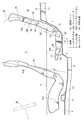
図9、図10、図11は車両のシート装置の他の実施例を示し、図9は全体構造を示す側面図、図10は図9の要部拡大側面図、図11はシートアレンジによる荷室空間X形成時の側面図である。 9, FIG. 10 and FIG. 11 show other embodiments of the vehicle seat device, FIG. 9 is a side view showing the overall structure, FIG. 10 is an enlarged side view of the main part of FIG. 9, and FIG. It is a side view at the time of chamber space X formation.
図9〜図11に示すように、この実施例ではシートバック52Bにおけるシートバックアッパ52Uを前方に移動させた時、その背面、詳しくは前方に向けて中折れさせたシートバックアッパ52Uの背面が上述のトンネル部9のトップデッキ部と略同一高さとなるように形成したものである。
As shown in FIGS. 9 to 11, in this embodiment, when the seat back upper 52U in the seat back 52B is moved forward, the back surface thereof, specifically, the back surface of the seat back upper 52U folded forward is formed. It is formed so as to have substantially the same height as the top deck portion of the
すなわち、上述のトンネル部9の上部には、リヤシートパン6の前端対応位置から該リヤシートパン6の前後方向中間対応位置にかけて、前低後高上のスラント部9aを形成し、このスラント部9aの後端高さをリヤフロア8の面と同一高さに設定すると共に、スラント部9aの後端からリヤフロア8にかけて後方に延びる水平部9bを形成し、シートバックアッパ52Uを、中折れ部56を支点として、前方に傾倒させて、このシートバックアッパ52Uを略水平状に成した時(図11参照)、該シートバックアッパ52Uの背面が上述のトンネル部9における水平部9bと略同一高さとなるように構成したものである。
That is, on the upper part of the
このように、図9〜図11で示した実施例においては、上記フロアパネル4の車幅方向中央部には、車室2内側へ突出したトンネル部9が設けられ、上記シートバック52B(特に、シートバックアッパ52U参照)はその背面が上記トンネル部9と略同一高さとなるように前傾可能に設けられたものである(図11参照)。
この構成によれば、前傾時のシートバック52B(この実施例では、シートバックアッパ52U)背面とトンネル部9のトップデッキ部とが略同一高さとなるので、荷室空間X(セキュリティボックス空間)を略完全な密閉空間と成すことができ、外部からの不正アクセスがさらに困難となるうえ、より一層人目につき難い荷室空間Xとなるので、盗難防止性のさらなる向上を図ることができる。
As described above, in the embodiment shown in FIGS. 9 to 11, the
According to this configuration, the rear surface of the seat back 52B (in this embodiment, the seat back upper 52U) and the top deck portion of the
図9〜図11で示したこの実施例2においても、その他の構成、作用、効果については、図1〜図8を参照して述べた先の実施例1と同様であるから、図9〜図11において、前図と同一の部分には、同一符号を付して、その詳しい説明を省略する。 Also in the second embodiment shown in FIGS. 9 to 11, other configurations, operations, and effects are the same as those in the first embodiment described with reference to FIGS. 1 to 8. In FIG. 11, the same parts as those in the previous figure are denoted by the same reference numerals, and detailed description thereof is omitted.
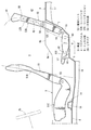
図12、図13、図14は車両のシート装置のさらに他の実施例を示し、図12は全体構造を示す側面図、図13は図12の要部拡大側面図、図14はシートアレンジによる荷室空間X形成時の側面図である。 12, 13, and 14 show still another embodiment of the vehicle seat device, FIG. 12 is a side view showing the overall structure, FIG. 13 is an enlarged side view of the main part of FIG. 12, and FIG. It is a side view at the time of cargo room space X formation.
先の各実施例1,2においてはシートバック52Bがシートバックアッパ52Uとシートバックロア52Lとを有していたが、この実施例3においてはシートバック52Bは、これらシートバックアッパ52Uとシートバックロア52Lとを備えていない。
また、この実施例3においては、シートバック52Bの上下方向中間部を支持する支点70を設け、この支点70を、ブラケット71を介して、リヤフロア8などのボディ側に支持させている。
In each of the first and second embodiments, the seat back 52B has the seat back upper 52U and the seat back lower 52L. However, in the third embodiment, the seat back 52B has the seat back upper 52U and the seat back. No lower 52L is provided.
Further, in the third embodiment, a fulcrum 70 that supports the intermediate portion in the vertical direction of the seat back 52B is provided, and the
そして、この実施例においては、図13に示す通常の着座状態から、図14の状態に成す時には、まず、前部支点57を中心としてシートクッション52Cを前方起立状態に保持し、次に、支点70を中心としてシートバック52Bの下部が前方に移動するように該シートバック52Bを回動させて、このシートバック52Bをトンネル部9の水平部9bおよびリヤフロア8と略平行に成すと、図14に示すように、サイドドアとしてのリヤドア50の側面(前図参照)と、シートクッション52Cと、トンネル部9の側面と、協同して荷物を収納可能な荷室空間Xを形成するように構成したものである。
In this embodiment, when the normal seating state shown in FIG. 13 is changed to the state shown in FIG. 14, first, the
このように、図12〜図14で示した実施例においても、車室2の底面を形成するフロアパネル4と、該フロアパネル4の車外側に設けられた乗降用開口35(図3参照)と、該乗降用開口35を開閉自在に覆うサイドドア(リヤドア50参照)と、を備え、上記サイドドア(リヤドア50参照)の側部に乗員が着座可能なシート(後列シート52参照)が設けられた車両のシート装置であって、上記シート(後列シート52)は、座面を形成するシートクッション52Cと、該シートクッション52Cの後部から上方に延びて背もたれ面を形成するシートバック52Bと、を備え、上記シートバック52Bが前方に移動し上記シートクッション52Cと上記サイドドア(リヤドア50参照)の側面と協同して荷物を収納可能な荷室空間Xを形成するように構成したものである(図12〜図14参照)。
As described above, also in the embodiment shown in FIGS. 12 to 14, the
この構成によれば、シートバック52Bを前方に移動させると、このシートバック52Bと、シートクッション52Cと、サイドドア(リヤドア50参照)の側面と協同して荷物を収納可能な荷室空間X(セキュリティボックス空間)が形成でき、該荷室空間Xの上方部は上記シートバック52B(特に、シートバックアッパ52U参照)で覆われる。
According to this configuration, when the seat back 52B is moved forward, the luggage space X (where the luggage can be stored in cooperation with the seat back 52B, the
このため、外部からアクセスしにくく、人目につき難い荷室空間X(セキュリティボックス空間)を簡単に形成することができ、また、該荷室空間Xに収納した小物などの物品の盗難防止性(いわゆる防盗性)を確保することができる。要するに、収納性確保と盗難防止性確保との両立を図ることができる。
また、上記荷室空間Xは小物入れ空間として適切なものであって、この小物入れ空間の簡易な形成と、使用時の見栄え確保と、の両立を図ることができる。
For this reason, it is possible to easily form a luggage room space X (security box space) that is difficult to access from the outside and difficult to see, and that the goods stored in the luggage room space X can be prevented from being stolen (so-called “theft”). Anti-theft). In short, it is possible to achieve both the secure storage and the anti-theft security.
Further, the cargo space X is suitable as an accessory space, and it is possible to achieve both a simple formation of the accessory space and ensuring appearance during use.
なお、この実施例3においてもシートバック52Bがロック部60を備え、またリヤドア50がロックピン68を備えた構成、シートクッション52Cがその前部支点57を中心に前方起立状態に移動可能となる構成、シート(後列シート52参照)はトンネル部9を挟んで車幅方向に左右一対設けられた構成、については、先の各実施例1,2と同様であって、ほぼ同様の作用、効果を奏するので、図12〜図14において前図と同一の部分には同一符号を付して、その詳しい説明を省略する。
In the third embodiment as well, the seat back 52B includes the
図15、図16は車両のシート装置のさらに他の実施例を示すものである。
実施例1〜3では4ドア4人乗りの車両を示したが、図15、図16に示すこの実施例では2ドア2人乗りで、かつ、ルーフが開閉可能なコンバチブルトップ80を具備する車両を示している。
15 and 16 show still another embodiment of the vehicle seat device.
In the first to third embodiments, a four-door four-seater vehicle is shown, but in this embodiment shown in FIGS. 15 and 16, a two-door two-seater vehicle and a convertible top 80 that can be opened and closed is provided. Shows the vehicle.
上述のコンバチブルトップ80は、フロントヘッダ81と、パッケージトレイ82の後端部と、の間に渡ってルーフが脱着可能に構成される一方、後部荷室42(いわゆるトランクルーム)の開口は開閉部材としてのトランクリッド83によって開閉自在に構成されており、トランクリッド83を図15に仮想線βで示すように開放することで、荷物の出し入れを容易に行なうように構成している。
The above-described convertible top 80 is configured such that the roof is detachable between the
また、この実施例においては、フロアパネル4後部とリヤフロア8前部とを上下方向に連結するバルクヘッド7の延長線上に、該バルクヘッド7上部とパッケージトレイ82前部とを連結する別のバルクヘッド84を備えており、このバルクヘッド84には、車室2と後部荷室42とを前後方向に連通させる開口部85が形成されている。
さらに、フロアパネル4の車外側には乗降用開口を設け、この乗降用開口を開閉自在に覆うサイドドアとしてのフロントドア86を設けている。
そして、このフロントドア86の側部車室2内には乗員が着座可能な前列シート51を設けている。
In this embodiment, another bulk that connects the upper part of the bulkhead 7 and the front part of the
Further, a boarding opening is provided outside the
A
この前列シート51は次のように構成されている。
すなわち、そのシートバック51Bは、下部に位置するシートバックロア51Lと、上部に位置してヘッドレストを兼ねる形状のシートバックアッパ51Uとを備えており、この前列シート51は、リクライニング支点53を中心として、シートバックロア51Lとシートバックアッパ51Uとが一体的にシートクッション51Cに対してリクライニング調整可能に構成されており、前席乗員の着座姿勢の自由度を確保するように構成している。
The
That is, the seat back 51B includes a seat back lower 51L located at the lower portion and a seat back upper 51U located at the upper portion and also serving as a headrest. The
また、前列シート51のシートバック51Bは、その中間部に、シートクッション51Cと所定の距離を確保して前傾可能と成す中折れ部56を備え、シートバックアッパ51Uを図15の仮想線に示す通常着座状態から同図に実線で示す中折れ状態に前方に倒伏させると、このシートバックアッパ51Uの背面と、リヤフロア8とで前後方向に連続した荷室面を形成すると共に、フロントドア86の側面と、シートクッション51Cと、トンネル部9の側面と、協同して荷物を収納可能な荷室空間(セキュリティボックス空間)X(図15参照)を形成するように構成している。
Further, the seat back 51B of the
つまり、上述のシートバックアッパ51Uを前方に中折れさせた場合、図示の便宜上、図16にハッチングを施して示す荷室空間X(セキュリティボックス空間)が形成される。この荷室空間Xは、インストルメントパネル46、ダッシュロアパネル3、フロアパネル4、シートクッション51C、シートバックロア51L、シートバックアッパ51U、フロントドア86の側面、トンネル部9の側面で囲繞されており、外部からアクセスしにくい空間となる。
しかも、シートバック51Bにおけるシートバックアッパ51Uには、その前傾状態をロックする複数のロック部60,60が設けられており、図15に実線で示すロック部60,60の位置と対応して、フロントドア86にはロックピン68,68(詳しくは、図6〜図8参照)が取付けられている。
That is, when the above-described seat back upper 51U is folded forward, a luggage space X (security box space) shown by hatching in FIG. 16 is formed for convenience of illustration. The cargo space X is surrounded by the
In addition, the seat back upper 51U in the seat back 51B is provided with a plurality of
このため、コンバチブルトップ80を取外した状態においても、荷室空間X内に収納した物品に対する盗難防止性(いわゆる防盗性)を確保することができる。なお、図15、図16において、87〜91はクロスメンバ、92はリヤバンパレインフォースメントである。 For this reason, even when the convertible top 80 is removed, it is possible to ensure the antitheft (so-called antitheft) for the articles stored in the cargo space X. In FIGS. 15 and 16, 87 to 91 are cross members, and 92 is a rear bumper reinforcement.
このように、図15、図16で示した実施例の車両のシート装置も、車室2の底面を形成するフロアパネル4と、該フロアパネル4の車外側に設けられた乗降用開口と、該乗降用開口を開閉自在に覆うサイドドア(フロントドア86参照)と、を備え、上記サイドドア(フロントドア86参照)の側部に乗員が着座可能なシート(前列シート51参照)が設けられた車両のシート装置であって、上記シート(前列シート51)は、座面を形成するシートクッション51Cと、該シートクッション51Cの後部から上方に延びて背もたれ面を形成するシートバック51Bと、を備え、上記シートバック51Bが前方に移動し上記シートクッション51Cと上記サイドドア(フロントドア86参照)の側面と協同して荷物を収納可能な荷室空間X(図16参照)を形成するように構成したものである。
As described above, the vehicle seat device of the embodiment shown in FIGS. 15 and 16 also includes the
この構成によれば、シートバック51B(この実施例では、シートバックアッパ51U)を前方に移動させると、このシートバック51Bと、シートクッション51Cと、サイドドア(フロントドア86参照)の側面と協同して荷物を収納可能な荷室空間X(セキュリティボックス空間)が形成でき、該荷室空間Xの上方部は上記シートバック51B(特に、そのシートバックアッパ51U参照)で覆われる。
According to this configuration, when the seat back 51B (in this embodiment, the seat back upper 51U) is moved forward, it cooperates with the seat back 51B, the
このため、外部からアクセスしにくく、人目につき難い荷室空間X(セキュリティボックス空間)を簡単に形成することができ、また、該荷室空間Xに収納した小物などの物品の盗難防止性(いわゆる防盗性)を確保することができる。要するに、収納性確保と盗難防止性確保との両立を図ることができる。
また、上記荷室空間Xは小物入れ空間として適切なものであって、この小物入れ空間の簡易な形成と、使用時の見栄え確保と、の両立を図ることができる。
For this reason, it is possible to easily form a luggage room space X (security box space) that is difficult to access from the outside and difficult to see, and that the goods stored in the luggage room space X can be prevented from being stolen (so-called “theft”). Anti-theft). In short, it is possible to achieve both the secure storage and the anti-theft security.
Further, the cargo space X is suitable as an accessory space, and it is possible to achieve both a simple formation of the accessory space and ensuring appearance during use.
しかも、上記車両は、ルーフが開閉可能なコンバチブルトップ80を備えたものである。
この構成によれば、コンバチブルトップ80を取外して、車両をオープンカー態様と成した時には、より一層の盗難防止性が要求されるが、上記構成により、この要求に対応することができる。
In addition, the vehicle includes a convertible top 80 that can be opened and closed.
According to this configuration, when the convertible top 80 is removed and the vehicle is configured in an open car mode, further antitheft performance is required, but the above configuration can meet this requirement.
この実施例4においても、シートバック51Bが中折れ部56を備えた構成、シートバック51Bの前傾状態をロックするロック部60およびロックピン68が設けられた構成、シートバック51Bのリクライニング調整可能な構成、については、先の各実施例1,2と同様であって、ほぼ同様の作用、効果を奏するので、図15、図16において前図と同一の部分には同一符号を付して、その詳しい説明を省略する。
Also in the fourth embodiment, the configuration in which the seat back 51B includes the folded
なお、実施例で開示したようにシートバック51Bのシートバックアッパ51Uを、中折れ部56を支点として前方に中折れさせた時、シートバックアッパ51Uの背面とリヤフロア8とで連続した荷室面を形成するように構成したので、図15、図16に仮想線で示すように、前後方向にコンパクトな車両においても、長尺物の荷物Yを効率的に搭載することができる。
As disclosed in the embodiment, when the seat back upper 51U of the seat back 51B is folded forward with the middle folded
この発明の構成と、上述の実施例との対応において、
この発明のサイドドアは、実施例1〜3のリヤドア50、実施例4のフロントドア86に対応し、
以下同様に、
シートは、実施例1〜3の後列シート52、実施例4の前列シート51に対応し、
ロック機構は、ロックピン68に対応するも、
この発明は、上述の実施例の構成のみに限定されるものではない。
例えば、実施例1〜3において、後列シート52の構造を実施例の状態のままとし、これに加えて、助手席側の前列シート51の構造を後列シート52と同様と成してもよい。
In the correspondence between the configuration of the present invention and the above-described embodiment,
The side door of the present invention corresponds to the
Similarly,
The sheet corresponds to the
The locking mechanism corresponds to the
The present invention is not limited to the configuration of the above-described embodiment.
For example, in the first to third embodiments, the structure of the
2…車室
4…フロアパネル
9…トンネル部
35…乗降用開口
50…リヤドア(サイドドア)
51…前列シート(シート)
51B…シートバック
51C…シートクッション
52…後列シート(シート)
52B…シートバック
52C…シートクッション
56…中折れ部
68…ロックピン(ロック機構)
80…コンバチブルトップ
86…フロントドア(サイドドア)
X…荷室空間
2 ...
51. Front row sheet (sheet)
51B ... Seat back 51C ...
52B ... Seat back 52C ...
80 ... convertible top 86 ... front door (side door)
X ... Cargo space
Claims (5)
該乗降用開口を開閉自在に覆うサイドドアと、を備え、
上記サイドドアの側部に乗員が着座可能なシートが設けられた車両のシート装置であって、
上記シートは、座面を形成するシートクッションと、該シートクッションの後部から上方に延びて背もたれ面を形成するシートバックと、を備え、
上記シートバックが前方に移動し上記シートクッションと上記サイドドアの側面と協同して荷物を収納可能な荷室空間を形成するように構成し、
上記サイドドアには、上記シートバックの前傾状態をロックするロック機構が設けられ、
上記ロック機構は、上記サイドドアの開閉に連動して作動する
車両のシート装置。 A floor panel forming the bottom surface of the passenger compartment, and a boarding / alighting opening provided outside the floor panel;
A side door that covers the opening for getting on and off freely,
A vehicle seat apparatus in which a seat on which a passenger can be seated is provided on a side portion of the side door,
The seat includes a seat cushion that forms a seat surface, and a seat back that extends upward from a rear portion of the seat cushion to form a backrest surface,
The seat back moves forward and is configured to cooperate with the seat cushion and the side of the side door to form a luggage compartment space capable of storing luggage,
The side door is provided with a lock mechanism for locking the forward tilt state of the seat back ,
The vehicle locking device is operated in conjunction with opening and closing of the side door .
請求項1に記載の車両のシート装置。 The vehicle seat device according to claim 1 , wherein the seat back includes a middle folding portion at a middle portion thereof that can be tilted forward while securing a predetermined distance from the seat cushion .
上記シートバックはその背面が上記トンネル部と略同一高さとなるように前傾可能に設けられた
請求項1または2に記載の車両のシート装置。 In the center of the floor panel in the vehicle width direction, a tunnel portion protruding toward the vehicle interior side is provided,
The vehicle seat device according to claim 1 or 2, wherein the seat back is provided so as to be inclined forward so that a back surface thereof is substantially the same height as the tunnel portion .
上記ロック機構は、上記シートバックの前傾状態をロックするシートバックロック用と、上記シートクッションの前方起立状態をロックするシートクッションロック用との複数を備えた
請求項1記載の車両のシート装置。 The seat is provided so that the seat cushion can move to the front standing state,
The locking mechanism includes a seat back lock for locking the forward tilting state of the seat back, <br/> claim 1 Symbol mounting comprising a plurality of the sheet cushion lock for locking the front upright state of the seat cushion Vehicle seat device.
請求項1〜4の何れか1に記載の車両のシート装置。 It said sheet sheet equipment for a vehicle according to any one of the pair provided with <br/> claims 1-4 arranged in the vehicle width direction.
Priority Applications (1)
| Application Number | Priority Date | Filing Date | Title |
|---|---|---|---|
| JP2008121749A JP5286920B2 (en) | 2008-05-08 | 2008-05-08 | Vehicle seat device |
Applications Claiming Priority (1)
| Application Number | Priority Date | Filing Date | Title |
|---|---|---|---|
| JP2008121749A JP5286920B2 (en) | 2008-05-08 | 2008-05-08 | Vehicle seat device |
Publications (3)
| Publication Number | Publication Date |
|---|---|
| JP2009269477A JP2009269477A (en) | 2009-11-19 |
| JP2009269477A5 JP2009269477A5 (en) | 2011-06-02 |
| JP5286920B2 true JP5286920B2 (en) | 2013-09-11 |
Family
ID=41436431
Family Applications (1)
| Application Number | Title | Priority Date | Filing Date |
|---|---|---|---|
| JP2008121749A Expired - Fee Related JP5286920B2 (en) | 2008-05-08 | 2008-05-08 | Vehicle seat device |
Country Status (1)
| Country | Link |
|---|---|
| JP (1) | JP5286920B2 (en) |
Family Cites Families (4)
| Publication number | Priority date | Publication date | Assignee | Title |
|---|---|---|---|---|
| DE541665C (en) * | 1932-01-14 | Werner Rappolt | Theft protection for motor vehicles | |
| JPS59132432U (en) * | 1983-02-25 | 1984-09-05 | マツダ株式会社 | automobile seat structure |
| JP2005112222A (en) * | 2003-10-09 | 2005-04-28 | Honda Motor Co Ltd | Seat structure of vehicle |
| JP2009137544A (en) * | 2007-12-10 | 2009-06-25 | Kanto Auto Works Ltd | Convertible vehicle |
-
2008
- 2008-05-08 JP JP2008121749A patent/JP5286920B2/en not_active Expired - Fee Related
Also Published As
| Publication number | Publication date |
|---|---|
| JP2009269477A (en) | 2009-11-19 |
Similar Documents
| Publication | Publication Date | Title |
|---|---|---|
| US7527315B2 (en) | Seat device for vehicle | |
| JP6156279B2 (en) | Rear seat airbag device for vehicle | |
| JP4649864B2 (en) | Vehicle seat system | |
| JP2004322822A (en) | Rear vehicle body structure of vehicle | |
| JP2004299641A (en) | Rear part car body structure of vehicle | |
| US9327621B2 (en) | Storage structure of off-road vehicle | |
| JP5286920B2 (en) | Vehicle seat device | |
| JP2010163112A (en) | Roof opening and closing structure for vehicle | |
| JP2009255861A (en) | Seat device of vehicle | |
| JP2010167872A (en) | Vehicular seatbelt arranging structure | |
| JP2010163113A (en) | Rear part vehicle body structure for vehicle | |
| JP2009269476A (en) | Vehicular seat device | |
| JP2010076674A (en) | Lower vehicle body structure for vehicle | |
| JP2009269477A5 (en) | ||
| JP2004314665A (en) | Seat structure of vehicle | |
| JP2007253669A (en) | Vehicle seat device | |
| JP7424239B2 (en) | Vehicle rear structure | |
| JP5477536B2 (en) | Vehicle seat belt device | |
| JP4626396B2 (en) | Rear cargo compartment structure for vehicles | |
| JP5036825B2 (en) | Convertible car with active rollover protection system | |
| JP5716605B2 (en) | Car seat equipment | |
| JP2004306799A (en) | Supporting structure of seat for vehicle | |
| JP4766386B2 (en) | Rear structure of roof-open vehicle | |
| JP5625784B2 (en) | Open roof structure of vehicle | |
| JP2006335164A (en) | Vehicular rear part luggage compartment structure |
Legal Events
| Date | Code | Title | Description |
|---|---|---|---|
| A521 | Written amendment |
Free format text: JAPANESE INTERMEDIATE CODE: A523 Effective date: 20110415 |
|
| A621 | Written request for application examination |
Free format text: JAPANESE INTERMEDIATE CODE: A621 Effective date: 20110415 |
|
| A977 | Report on retrieval |
Free format text: JAPANESE INTERMEDIATE CODE: A971007 Effective date: 20130118 |
|
| A131 | Notification of reasons for refusal |
Free format text: JAPANESE INTERMEDIATE CODE: A131 Effective date: 20130129 |
|
| A521 | Written amendment |
Free format text: JAPANESE INTERMEDIATE CODE: A523 Effective date: 20130312 |
|
| TRDD | Decision of grant or rejection written | ||
| A01 | Written decision to grant a patent or to grant a registration (utility model) |
Free format text: JAPANESE INTERMEDIATE CODE: A01 Effective date: 20130507 |
|
| A61 | First payment of annual fees (during grant procedure) |
Free format text: JAPANESE INTERMEDIATE CODE: A61 Effective date: 20130520 |
|
| R150 | Certificate of patent or registration of utility model |
Ref document number: 5286920 Country of ref document: JP Free format text: JAPANESE INTERMEDIATE CODE: R150 |
|
| LAPS | Cancellation because of no payment of annual fees |