JP5281925B2 - Game machine directing device - Google Patents

Game machine directing device Download PDF

Info

Publication number
JP5281925B2
JP5281925B2 JP2009046246A JP2009046246A JP5281925B2 JP 5281925 B2 JP5281925 B2 JP 5281925B2 JP 2009046246 A JP2009046246 A JP 2009046246A JP 2009046246 A JP2009046246 A JP 2009046246A JP 5281925 B2 JP5281925 B2 JP 5281925B2
Authority
JP
Japan
Prior art keywords
cam
movable
state
game
movable part
Prior art date
Legal status (The legal status is an assumption and is not a legal conclusion. Google has not performed a legal analysis and makes no representation as to the accuracy of the status listed.)
Expired - Fee Related
Application number
JP2009046246A
Other languages
Japanese (ja)
Other versions
JP2010200790A (en
Inventor
修人 榎本
政和 松井
Current Assignee (The listed assignees may be inaccurate. Google has not performed a legal analysis and makes no representation or warranty as to the accuracy of the list.)
Kyoraku Industrial Co Ltd
Original Assignee
Kyoraku Industrial Co Ltd
Priority date (The priority date is an assumption and is not a legal conclusion. Google has not performed a legal analysis and makes no representation as to the accuracy of the date listed.)
Filing date
Publication date
Application filed by Kyoraku Industrial Co Ltd filed Critical Kyoraku Industrial Co Ltd
Priority to JP2009046246A priority Critical patent/JP5281925B2/en
Publication of JP2010200790A publication Critical patent/JP2010200790A/en
Application granted granted Critical
Publication of JP5281925B2 publication Critical patent/JP5281925B2/en
Expired - Fee Related legal-status Critical Current
Anticipated expiration legal-status Critical

Links

Images

Landscapes

  • Pinball Game Machines (AREA)
  • Display Devices Of Pinball Game Machines (AREA)

Abstract

<P>PROBLEM TO BE SOLVED: To make a movable part for a performance perform complicated operations, using the driving means of a small size and low power consumption. <P>SOLUTION: In the performance device, a performance hand-object 117 rotates a plate cam 511 together with a groove cam 581 by rotationally driving the groove cam 581 by a rotary driving means by a motor drive unit 503 and gears 504 and 505, transmits power from the groove cam 581 through a first engagement turning member to the movable part 510 to make the movable part 510 perform the operation, also rotates the plate cam 511, and transmits the power from the plate cam 511 through a second engagement turning member 512 to a turning decoration member 524 to make the turning decoration member 524 perform the operation. Thus, the movable part 510 for the performance is made to perform the complicated operation using the driving means of the small size and the low power consumption. <P>COPYRIGHT: (C)2010,JPO&amp;INPIT

Description

本発明は板状に形成された遊技板の前面側に遊技球が落下する遊技領域を有する遊技盤を備える遊技機の演出装置に関する。   The present invention relates to an effect device for a gaming machine including a gaming board having a gaming area where a gaming ball falls on the front side of a gaming board formed in a plate shape.

従来、パチンコ機と呼ばれる遊技機は、遊技球が図示しない球送り装置によって1球ずつ発射レール上に送り出され、送り出された遊技球が打球発射装置に打ち出されて遊技盤の案内レールの外レールに沿って遊技領域に導かれ、この遊技領域に導かれた遊技球が入賞口に入賞することで所定数の賞球を払い出すようになっている。   Conventionally, a game machine called a pachinko machine has a game ball sent out one by one on a launching rail by a ball feeding device (not shown), and the sent out game ball is launched into the hitting ball launching device to be an outer rail of the guide rail of the game board. The game balls are guided to the game area, and the game balls guided to the game area win a prize opening to pay out a predetermined number of prize balls.

一般的に遊技盤の表面に配設されるランプ飾りや入賞口等の盤面部品には、例えば特許文献1に記載のように、その盤面部品の前面部分に色の異なる複数の粒状体を視認可能なように配設し、基板の裏面に設けられたランプで粒状体を照明する電飾構造が施されている。
また、発展型リーチを採用するパチンコ遊技機などにおいては、例えば特許文献2に記載のように、可動物(例えば人形)に対して動作を行わせる機械式の演出装置を設けることにより、新規で斬新な遊技機を提供するものがある。
このような従来の演出装置は、電動モータやソレノイド等の電磁力で作動する駆動手段が可動物に動力を伝達することで可動物を動かしている。
In general, on a board part such as a lamp decoration or a prize opening arranged on the surface of a game board, for example, as described in Patent Document 1, a plurality of particles having different colors are visually recognized on the front part of the board part. An electrical decoration structure is provided that illuminates the granular material with a lamp that is arranged as possible and is provided on the back surface of the substrate.
In addition, in pachinko machines and the like that adopt advanced reach, for example, as described in Patent Document 2, by providing a mechanical presentation device that operates a movable object (for example, a doll), it is novel. Some offer innovative gaming machines.
In such a conventional rendering device, a driving means that operates by electromagnetic force such as an electric motor or a solenoid moves the movable object by transmitting power to the movable object.

実開平7−452号公報Japanese Utility Model Publication No. 7-452 特開2008−173239号公報JP 2008-173239 A

上記のように従来の遊技機の演出装置では、可動物に対して複雑な動作を行わせる場合、駆動手段として大型ソレノイドを複数設ける等の高価で電力を要する駆動手段を用いることになるので、製造コストの抑制が困難であった。   As described above, in the conventional game machine effect device, when a complicated operation is performed on a movable object, an expensive and power-consuming drive unit such as a plurality of large solenoids is used as the drive unit. It was difficult to control manufacturing costs.

本発明は、上記の問題に鑑み、小型かつ低消費電力の駆動手段を用いて演出用の可動部に複雑な動作を行わせることができる遊技機の演出装置を提供することを目的とする。   In view of the above problems, an object of the present invention is to provide an effect device for a gaming machine that can cause a moving portion for effect to perform a complicated operation using a small-sized and low power consumption driving means.

請求項1に記載の遊技機の演出装置は、板状に形成された遊技板の前面側に遊技球が落下する遊技領域を有する遊技盤を備える遊技機の演出装置であって、
前記遊技板に対して所定の方向に往復運動可能な状態で設けられた可動部と、
回転軸からカム面までの距離が回転角により異なるカムと、
前記遊技板に対して回動可能な状態で設けられ第1の部分で前記可動部と摺動可能な状態で係合するとともに、第2の部分で前記カムのカム面と摺動可能な状態で係合する係合回動部材と、
前記カムを回転駆動する回転駆動手段とを備え、
前記回転駆動手段が前記カムを回転駆動することで当該カムから係合回動部材を介して前記可動部に動力を伝達して当該可動部に動作を行わせることを特徴とする。
請求項2に記載の遊技機の演出装置は、
板状に形成された遊技板の前面側に遊技球が落下する遊技領域を有する遊技盤を備える遊技機の演出装置であって、
前記遊技板に対して所定の方向に往復運動可能な状態で設けられた可動部と、
前記可動部に移動可能な状態で設けられた移動装飾部材と、
回転軸からカム面までの距離が回転角により異なる第1のカムと、
第1のカムと回転軸を一致させて前記第1のカムに固定され、回転軸からカム面までの距離が回転角により異なる第2のカムと、
前記遊技板に対して回動可能な状態で設けられ第1の部分で前記可動部と摺動可能な状態で係合するとともに、第2の部分で前記第1のカムのカム面と摺動可能な状態で係合する第1の係合回動部材と、
前記遊技板に対して回動可能な状態で設けられ第1の部分で前記回動装飾部材と係合するとともに、第2の部分で前記第2のカムのカム面と摺動可能な状態で係合する第2の係合回動部材と、
前記第1のカムを回転駆動する回転駆動手段とを備え、
前記回転駆動手段が前記第1のカムを回転駆動することで前記第1のカムとともに前記第2のカムを回転させ、当該第1のカムから前記第1の係合回動部材を介して前記可動部に動力を伝達して当該可動部に動作を行わせるとともに、前記第2のカムを回転させ当該第2のカムから前記第2の係合回動部材を介して前記移動装飾部材に動力を伝達して当該移動装飾部材に動作を行わせることを特徴とする。
前記遊技板には演出用の映像を画面に表示する映像表示手段を有し、前記可動部は前記往復運動により前記映像表示手段の画面の手前側を移動することを特徴とする(請求項3)。
The effect device for a gaming machine according to claim 1 is an effect device for a gaming machine including a game board having a game area in which a game ball falls on the front side of a game board formed in a plate shape,
A movable part provided in a state capable of reciprocating in a predetermined direction with respect to the game board;
A cam whose distance from the rotation axis to the cam surface varies depending on the rotation angle;
Provided in a rotatable state with respect to the game board and engaged with the movable portion in a slidable state at the first portion, and slidable with the cam surface of the cam at the second portion An engaging rotation member to be engaged with,
Rotational drive means for rotationally driving the cam,
The rotational drive means rotationally drives the cam, whereby power is transmitted from the cam to the movable portion via an engaging rotation member to cause the movable portion to perform an operation.
An effect device for a gaming machine according to claim 2,
A rendering device of a gaming machine comprising a gaming board having a gaming area where a gaming ball falls on the front side of a gaming board formed in a plate shape,
A movable part provided in a state capable of reciprocating in a predetermined direction with respect to the game board;
A movable decorative member provided in a movable state on the movable part;
A first cam in which the distance from the rotation shaft to the cam surface varies depending on the rotation angle;
A second cam that is fixed to the first cam with the first cam and the rotation axis aligned, and the distance from the rotation axis to the cam surface varies depending on the rotation angle;
It is provided in a rotatable state with respect to the game board, and engages with the movable portion in a slidable state at the first portion, and slides with the cam surface of the first cam at the second portion. A first engaging rotation member that engages in a possible state;
It is provided in a rotatable state with respect to the game board, and engages with the rotating decorative member at the first portion, and is slidable with the cam surface of the second cam at the second portion. A second engaging rotation member to be engaged;
Rotational drive means for rotationally driving the first cam;
The rotational driving means rotationally drives the first cam to rotate the second cam together with the first cam, and from the first cam through the first engagement rotating member, the Power is transmitted to the movable part to cause the movable part to perform an operation, and the second cam is rotated to power the movable decorative member from the second cam via the second engagement rotating member. Is transmitted to cause the movable decorative member to perform an operation.
The game board includes video display means for displaying a video for production on a screen, and the movable portion moves on the front side of the screen of the video display means by the reciprocating motion. ).

いずれの場合にも、前記回転駆動手段が前記カムを回転駆動することで当該カムから係合回動部材を介して前記可動部に動力を伝達して当該可動部に動作を行わせるので、小型かつ低消費電力の駆動手段を用いて演出用の可動部に複雑な動作を行わせることができ、遊技機の低消費電力化を行えるとともに、製造コストの抑制し、遊技機における演出装置の配置場所の制約を緩和することができる。   In any case, the rotational drive means rotationally drives the cam so that power is transmitted from the cam to the movable part via the engaging rotation member, and the movable part is operated. In addition, it is possible to cause the moving parts for presentation to perform complicated operations using low power consumption driving means, reduce the power consumption of the gaming machine, reduce the manufacturing cost, and arrange the rendering device in the gaming machine Location constraints can be relaxed.

第1及び第2の係合回動部材は、必要に応じて伸縮やジョイントを介した折り曲が可能な構造にしてもよい。   The first and second engaging rotation members may be structured so that they can be expanded and contracted and bent via a joint as necessary.

従来の遊技機の演出装置では、電動モータやソレノイド等の電磁力で作動する駆動手段が可動物に動力を伝達することで可動物を動かしているが、電動モータやソレノイド等の電磁力で作動する駆動手段は、加減速の制御範囲が狭く、可動物を複雑な動作を行わせるには大型かつ高価で電力を要する駆動手段を用いることになるので、省電力化及び製造コストの抑制が困難であるとともに、遊技機における駆動手段の配置場所に制約が大きかった。
これに対し、本発明では小型かつ低消費電力の駆動手段を用いて小型かつ低消費電力の駆動手段を用いて演出用の可動部に複雑な動作を行わせることができ、遊技機の低消費電力化を行えるとともに、製造コストの抑制し、遊技機における演出装置の配置場所の制約を緩和することができる。
In the conventional game machine directing device, the drive means that operates by electromagnetic force such as an electric motor or solenoid moves the movable object by transmitting power to the movable object, but it operates by electromagnetic force such as the electric motor or solenoid. The driving means to be used has a narrow acceleration / deceleration control range, and a large, expensive and power-consuming driving means is used to perform a complex operation of the movable object, so that it is difficult to save power and control manufacturing costs. In addition, there are significant restrictions on the location of the driving means in the gaming machine.
On the other hand, in the present invention, a small and low power consumption driving means can be used to cause the movable part for production to perform complicated operations using a small and low power consumption driving means, thereby reducing the consumption of the gaming machine. Electricity can be achieved, manufacturing costs can be suppressed, and restrictions on the location of the rendering device in the gaming machine can be relaxed.

本発明によれば、小型かつ低消費電力の駆動手段を用いて演出用の可動部に複雑な動作を行わせることができ、遊技機の低消費電力化を行えるとともに、製造コストの抑制し、遊技機における演出装置の配置場所の制約を緩和することができ、遊技機の設計の自由度を高めることができる。   According to the present invention, it is possible to perform a complicated operation on the moving part for production using a small and low power consumption driving means, to reduce the power consumption of the gaming machine, and to suppress the manufacturing cost, It is possible to relax restrictions on the location of the rendering device in the gaming machine, and to increase the degree of freedom in designing the gaming machine.

本発明に係る実施形態の遊技機の構成例を示した正面図である。It is the front view which showed the structural example of the game machine of embodiment which concerns on this invention. 本発明に係る実施形態の制御手段のブロック図である。It is a block diagram of the control means of the embodiment concerning the present invention. 本発明に係る実施形態の遊技盤を示す正面図である。It is a front view which shows the game board of embodiment which concerns on this invention. 本発明に係る実施形態の遊技盤を示す斜視図である。It is a perspective view which shows the game board of embodiment which concerns on this invention. 本発明に係る実施形態の演出役物の分解斜視図である。It is a disassembled perspective view of the stage effect object of embodiment which concerns on this invention. 本発明に係る実施形態の第1の係合回動部材及びその周辺部の斜視図である。It is a perspective view of the 1st engagement rotation member of the embodiment concerning the present invention, and its peripheral part. 本発明に係る実施形態の第2の係合回動部材の斜視図である。It is a perspective view of the 2nd engagement rotation member of the embodiment concerning the present invention. 本発明に係る実施形態の演出役物の組み立てた状態の後方右斜め上側から見た斜視図である。It is the perspective view seen from back right diagonal upper side of the state which the production | presentation combination of embodiment which concerns on this invention was assembled. 本発明に係る実施形態の演出役物の組み立てた状態の前方右斜め上側から見た斜視図である。It is the perspective view seen from the front right diagonal upper side of the state which assembled the production | presentation actor of embodiment which concerns on this invention. 本発明に係る実施形態の演出役物の蓋体を透明にした状態で示す斜視図である。It is a perspective view shown in the state which made transparent the cover body of the director in the embodiment which concerns on this invention. 本発明に係る実施形態の演出役物の前半の動作を説明する演出役物のA−A線断面図である。It is AA sectional view taken on the line of the director in explaining the first half operation of the director in the embodiment according to the present invention. 本発明に係る実施形態の演出役物の前半の動作を説明する演出役物の図9に示したB−B線断面図である。It is the BB sectional view taken on the line B-B shown in FIG. 9 of the director to explain the first half operation of the director of the embodiment according to the present invention. 本発明に係る実施形態の演出役物の後半の動作を説明する演出役物の図9に示したB−B線断面図である。FIG. 10 is a cross-sectional view taken along line B-B of FIG. 本発明に係る実施形態の演出役物の前半の動作を説明する演出役物の正面図である。It is a front view of the director who explains the operation of the first half of the director of the embodiment according to the present invention. 本発明に係る実施形態の演出役物の後半の動作を説明する演出役物の正面図である。It is a front view of the director who explains the latter half operation of the director of the embodiment concerning the present invention.

以下、本発明の実施形態について図面を参照しながら具体的に説明する。   Hereinafter, embodiments of the present invention will be specifically described with reference to the drawings.

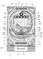
図1は 遊技機の構成例を示した正面図である。   FIG. 1 is a front view showing a configuration example of a gaming machine.

初めに遊技機全体の説明をする。
図1において、遊技機1は、機枠又は機体として所定の外郭方形枠サイズに構成された固定保持用の外枠11と、この外枠11の前側に設けられ、この外枠11に合わせて方形枠サイズに構成された前枠12とを備えている。
前枠12は、正面左側上下部に配設された開閉連結支持機構13a、13bを介して外枠11に開閉(片持ち横開き)可能に組付けるとともに、正面右側内部に配設された施錠装置14を利用して閉鎖状態に保持される。
前枠12の正面側には、前枠12の前側面域に合わせた方形状のガラス扉15及び受け皿ユニット16が共に横開き開閉及び着脱が可能に組付けられており、施錠装置14および図示しないロック機構を利用して前枠12の前面を覆う閉止状態で保持される。
受け皿ユニット16には、球払出口から払い出された遊技球を貯留して整列させる球皿部17が設けられる。
前枠12には、パチンコゲームを展開し得る遊技盤101が、着脱交換可能にセット保持されている。遊技盤101は、前面の遊技領域103を前記ガラス扉15の正面に臨ませている。
前枠12の前記ガラス扉15の下方位置には、発射部292(図2参照)を備える操作ハンドル113が配置され、発射部292の駆動によって発射された遊技球がレール102a、102b間を上昇して遊技盤101の上部位置に達した後、遊技領域103内を落下する。遊技領域103には、遊技球を不特定の方向に向けて落下させるための複数の釘に加え、遊技球の落下方向を変化させる風車や入球口が配置されている。
First, the entire gaming machine will be described.
In FIG. 1, the gaming machine 1 is provided as a machine frame or a machine body or a fixed outer frame 11 having a predetermined rectangular frame size, and is provided on the front side of the outer frame 11. And a front frame 12 having a rectangular frame size.
The front frame 12 is assembled to the outer frame 11 so as to be openable and closable (cantilevered laterally open) via the open / close connection support mechanisms 13a and 13b provided on the upper left and upper parts of the front left side, and is locked on the inner side of the front right side. The device 14 is used to maintain the closed state.
On the front side of the front frame 12, a rectangular glass door 15 and a tray unit 16 that match the front side area of the front frame 12 are assembled so as to be able to be opened and closed sideways and attached and detached. It is held in a closed state that covers the front surface of the front frame 12 using a locking mechanism that does not.
The tray unit 16 is provided with a ball tray portion 17 for storing and aligning game balls paid out from the ball payout outlet.
A game board 101 capable of developing a pachinko game is set and held in the front frame 12 so as to be detachable and replaceable. The game board 101 has the front game area 103 facing the front surface of the glass door 15.
An operation handle 113 having a launching part 292 (see FIG. 2) is disposed below the glass door 15 in the front frame 12, and a game ball launched by driving the launching part 292 rises between the rails 102a and 102b. Then, after reaching the upper position of the game board 101, the game area 103 is dropped. In the game area 103, in addition to a plurality of nails for dropping a game ball in an unspecified direction, a windmill and a entrance for changing the fall direction of the game ball are arranged.

遊技領域103の中央部分には中央役物2が配置されている。中央役物2には、例えば液晶表示器(LCD)を用いた図柄表示部104が配置されている。
図柄表示部104の下方には遊技球を受入れ可能な第1始動口105が配置され、第1始動口105の下方には一対の可動片120a(図3参照)を有する第2始動口120が配置されている。第2始動口120は一対の可動片120a(図3参照)が閉状態のときに遊技球の受入れを困難にし、開状態のときに第1始動口105よりも遊技球の受入れを容易にする。
In the central portion of the game area 103, the central accessory 2 is arranged. In the central accessory 2, a symbol display unit 104 using a liquid crystal display (LCD), for example, is arranged.
A first start port 105 capable of receiving a game ball is disposed below the symbol display unit 104, and a second start port 120 having a pair of movable pieces 120a (see FIG. 3) is disposed below the first start port 105. Has been placed. The second starting port 120 makes it difficult to receive the game ball when the pair of movable pieces 120a (see FIG. 3) is closed, and makes it easier to receive the game ball than the first starting port 105 when the pair is open. .

図柄表示部104の左側には、遊技球の通過を検出し、第2始動口120を一定時間だけ開放させる普通図柄の抽選を行うための入賞ゲート106が配置されている。入賞ゲート106の下方位置等には、遊技球が入球したときに所定数(例えば10個)の賞球払い出しの権利を獲得する普通入賞口107a、107b、107cが配置されている。遊技領域103の最下部にはどの入球口にも入球しなかった遊技球を回収する回収口108が配置されている。   On the left side of the symbol display unit 104, a winning gate 106 for detecting the passing of a game ball and performing lottery of a normal symbol for opening the second start port 120 for a predetermined time is arranged. In the lower position of the winning gate 106, etc., normal winning ports 107a, 107b, 107c for obtaining a predetermined number (for example, ten) of paying out prize balls when a game ball enters are arranged. At the bottom of the game area 103, a collection port 108 for collecting game balls that have not entered any of the entrances is disposed.

図柄表示部104の右下には、遊技球が入球したときに所定数(例えば10個)の賞球払い出しの権利を獲得する普通入賞口107dが配置されている。
さらに、普通入賞口107dの下には、主制御基板201(図2参照)に設けられた第1特別図柄抽選手段による抽選結果を表示する第1特別図柄表示器82(図3参照)、及び主制御基板201(図2参照)に設けられた第2特別図柄抽選手段による抽選結果を表示する第2特別図柄表示器83(図3参照)が配置されている。これら両表示器82、83には特別図柄が変動表示されていると共に、所定時間経過後に所定の図柄が停止表示され、始動口への遊技球の入球を契機とする抽選の結果が表示されている。両表示器82、83には複数のLEDが使用され、特別図柄の変動表示の開始に伴ってLEDが点滅することで、現在抽選中であるかのような印象を遊技者に与える。所定時間経過後には、抽選結果に応じて予め設定されたLEDが点灯表示し、遊技者に抽選結果が報知されている。
On the lower right side of the symbol display section 104, a normal winning opening 107d for obtaining a predetermined number (for example, ten) of paying out prize balls when a game ball enters is arranged.
Furthermore, below the normal winning opening 107d, a first special symbol display 82 (see FIG. 3) for displaying a lottery result by the first special symbol lottery means provided on the main control board 201 (see FIG. 2), and A second special symbol display 83 (see FIG. 3) for displaying the lottery result by the second special symbol lottery means provided on the main control board 201 (see FIG. 2) is arranged. These two indicators 82 and 83 display special symbols in a variable manner, and after a predetermined time has elapsed, the predetermined symbols are stopped and displayed, and the results of a lottery triggered by the entry of a game ball into the starting port are displayed. ing. A plurality of LEDs are used for both indicators 82 and 83, and the LED blinks as the special symbol variation display starts, giving the player the impression that the lottery is currently being drawn. After a predetermined time has elapsed, an LED preset according to the lottery result is lit up and the lottery result is notified to the player.

特別図柄の変動表示中に第1始動口105、あるいは第2始動口120に遊技球が入球すると、当該入球によって得られる特別図柄の変動表示の権利(以下「保留球」という)が留保されている。この留保された保留球の数は第1特別図柄保留表示器84(図3参照)及び第2特別図柄保留表示器85(図3参照)に表示されている。   If a game ball enters the first starting port 105 or the second starting port 120 during the special symbol variation display, the right to display the special symbol variation display (hereinafter referred to as “reserved ball”) reserved by the entry is reserved. Has been. The number of reserved balls reserved is displayed on the first special symbol hold indicator 84 (see FIG. 3) and the second special symbol hold indicator 85 (see FIG. 3).

特別図柄の変動表示中に入賞ゲート106に遊技球が入球すると、普通図柄抽選手段による抽選が行われるが、この抽選結果を表示する普通図柄表示器81(図3参照)が上記両表示器82、83の付近に配置されている。普通図柄の変動表示中に入賞ゲート106に遊技球が入球することによって得られる普通図柄の変動表示の権利、すなわち保留球の数が普通図柄保留表示器86(図3参照)に表示されている。   When a game ball enters the winning gate 106 during the special symbol variation display, the normal symbol lottery means draws a lottery, and the normal symbol display 81 (see FIG. 3) for displaying the lottery result displays the above two indicators. 82 and 83 are arranged in the vicinity. The right of the normal symbol change display obtained by the game ball entering the winning gate 106 during the normal symbol change display, that is, the number of reserved balls is displayed on the normal symbol hold indicator 86 (see FIG. 3). Yes.

図柄表示部104は第1始動口105、または第2始動口120に遊技球が入球したときに複数の装飾図柄の変動表示を開始し、所定時間経過後に当該装飾図柄の変動を停止させる。停止時に特定図柄(例えば「777」)が揃えば、大当たり遊技(長当たり遊技)を実行する権利を獲得したこととなり、その後、大当たり遊技(長当たり遊技)が開始される。大当たり遊技(長当たり遊技)が開始されると、遊技領域103の下方に位置する大入賞口ユニット9における開閉扉91が一定時間、開放する動作を所定回数(例えば15回)繰り返し、入球した遊技球に対応する賞球が払い出されている。   When the game ball enters the first start port 105 or the second start port 120, the symbol display unit 104 starts a variation display of a plurality of decorative symbols, and stops the variation of the decorative symbol after a predetermined time has elapsed. If a specific symbol (for example, “777”) is prepared at the time of stoppage, it means that the right to execute the jackpot game (long win game) is acquired, and then the jackpot game (long hit game) is started. When the big hit game (long win game) is started, the opening / closing door 91 in the big winning opening unit 9 located below the game area 103 is opened for a predetermined time repeatedly for a predetermined number of times (for example, 15 times). Prize balls corresponding to game balls are paid out.

大入賞口ユニット9は遊技盤101に設けられた大入賞口93を開閉する開閉扉91を開閉自在に支持し、開閉扉91が大入賞口93の前面(表面)側に位置した状態で、遊技盤101の背面に設置されている。開閉扉91は通常時には閉鎖して大入賞口93を閉塞しており、大入賞口93に遊技球が入球することを阻止している。大当たり遊技が開始されたときには、大入賞口開閉ソレノイド43への通電により開閉扉91が開放して大入賞口93を開放させる。大入賞口93の開放時には、開閉扉91が遊技球を大入賞口93内に導くための受け皿として機能するため、大入賞口93に遊技球が入球可能となる。   The big prize opening unit 9 supports an open / close door 91 that opens and closes the big prize opening 93 provided on the game board 101 so as to freely open and close, and the open / close door 91 is located on the front (front) side of the big prize opening 93, It is installed on the back of the game board 101. The open / close door 91 is normally closed to close the grand prize opening 93, thereby preventing a game ball from entering the big prize opening 93. When the big hit game is started, the open / close door 91 is opened by energizing the special winning opening / closing solenoid 43 and the special winning opening 93 is opened. When the big prize opening 93 is opened, the open / close door 91 functions as a tray for guiding the game ball into the big prize opening 93, so that the game ball can enter the big prize opening 93.

また、前記前枠12の上側と下側には複数のライト112を備えた演出ライト111(ランプユニット)が設置されている。   An effect light 111 (lamp unit) having a plurality of lights 112 is installed on the upper and lower sides of the front frame 12.

前枠12の下側には、受け皿ユニット16が設置されている他、前述の操作ハンドル113が配置されている。操作ハンドル113は遊技盤101から遊技者側へ突出し、上記発射部の駆動によって遊技球を発射させる際に遊技者によって操作されている。   A tray unit 16 is installed below the front frame 12, and the above-described operation handle 113 is disposed. The operation handle 113 protrudes from the game board 101 to the player side, and is operated by the player when the game ball is fired by driving the launching portion.

操作ハンドル113は上記発射部を駆動させて遊技球を発射させる発射指示部材114を備えている。発射指示部材114は操作ハンドル113の外周部に、遊技者から見て右回りに回転可能に設けられ、遊技者によって直接操作されているときに発射部に遊技球発射の指示を与える。操作ハンドル113には遊技者が発射指示部材114を直接操作していることを検出するセンサ等が内蔵されている。   The operation handle 113 includes a firing instruction member 114 that drives the launching portion to launch a game ball. The firing instruction member 114 is provided on the outer peripheral portion of the operation handle 113 so as to rotate clockwise as viewed from the player, and gives a launching command to the launching portion when being directly operated by the player. The operation handle 113 incorporates a sensor or the like that detects that the player directly operates the firing instruction member 114.

中央役物2における図柄表示部104の上側及び側方(図1においては紙面右側)には、演出用の役物(以下、「演出役物」という)115、116が配置されている。演出役物115、116は例えばモータによって駆動されるようになっている。中央役物2における図柄表示部104の左下側には、本実施形態の要部となる演出役物117が配置されている。   On the upper side and the side (right side of the drawing in FIG. 1) of the symbol display unit 104 in the central accessory 2, effects for the effect (hereinafter referred to as “direction effects”) 115 and 116 are arranged. The directors 115 and 116 are driven by a motor, for example. On the lower left side of the symbol display unit 104 in the central combination 2, a production combination 117 serving as a main part of the present embodiment is arranged.

前枠12の下側にはまた、遊技者による操作を受け付けるチャンスボタン118が配置されている。チャンスボタン118の操作は例えば遊技中における特定のリーチ演出に際し、チャンスボタン118の操作を促すガイダンスが表示されている間有効となる。   A chance button 118 for accepting an operation by the player is also arranged below the front frame 12. The operation of the chance button 118 is effective while the guidance for prompting the operation of the chance button 118 is displayed, for example, in the case of a specific reach effect during the game.

前枠12には、演出効果音、または不正を知らしめる音声を出力するスピーカ277(図2参照)が組み込まれている。スピーカ277は高音・中音・低音の領域を出力できる機能を有し、通常演出時は高音・中音・低音をバランス良く出力するが、後述する特別演出時、または不正等があった場合には周りに良く聞こえるように高音領域を高く出力するように制御されている。
(制御手段の内部構成)
図2に遊技機1の制御手段の内部構成を示すが、ここに示すように制御手段200は主に主制御基板201、副制御基板202、賞球制御基板203、及びランプ制御基板206の複数の制御基板から構成されている。
The front frame 12 incorporates a speaker 277 (see FIG. 2) that outputs a production effect sound or a sound that informs fraud. The speaker 277 has a function capable of outputting high, medium, and low sound areas, and outputs a high sound, medium sound, and low sound in a well-balanced manner during normal production, but in the case of special production described later or when there is fraud, etc. Is controlled to output a high treble region so that it can be heard well.
(Internal structure of control means)
FIG. 2 shows the internal configuration of the control means of the gaming machine 1. As shown here, the control means 200 mainly includes a plurality of main control boards 201, sub-control boards 202, prize ball control boards 203, and lamp control boards 206. It is comprised from the control board.

主制御基板201は遊技機1の遊技に関する基本動作を制御し、ROM201bに記憶されたプログラムに基づき、遊技内容の進行に伴う基本処理を実行するCPU201aと、CPU201aの演算処理時におけるデータのワークエリアとして機能するRAM201c等を備える。主制御基板201は第1始動口105、もしくは第2始動口120への遊技球の入球を契機として、大当たり抽選を行うと共に、その抽選結果に基づいてROM201bに記憶されている演出に係わるコマンドの選択を行う。   The main control board 201 controls basic operations related to the game of the gaming machine 1, and based on a program stored in the ROM 201b, executes a basic process associated with the progress of the game content, and a work area for data during the arithmetic processing of the CPU 201a RAM 201c or the like functioning as The main control board 201 performs lottery lottery triggered by a game ball entering the first start port 105 or the second start port 120, and commands related to effects stored in the ROM 201b based on the lottery result Make a selection.

主制御基板201の入力側には、第1始動口105に遊技球が入球したことを検出する第1始動口検出部221と、第2始動口120に遊技球が入球したことを検出する第2始動口検出部225と、入賞ゲート106を遊技球が通過したことを検出するゲート検出部222と、普通入賞口107a、107b、107cに入球した遊技球を検出する普通入賞口検出部223と、大入賞口ユニット9に入球した遊技球を検出する大入賞口検出部224とが接続されている。   On the input side of the main control board 201, a first start port detecting unit 221 that detects that a game ball has entered the first start port 105 and a game ball that has entered the second start port 120 are detected. The second start opening detection unit 225, the gate detection unit 222 for detecting that the game ball has passed through the winning gate 106, and the normal winning port detection for detecting the game ball that has entered the normal winning ports 107a, 107b, 107c. The unit 223 is connected to a special winning opening detection unit 224 that detects a game ball that has entered the special winning opening unit 9.

主制御基板201の出力側には役物作動装置231が接続されている。本実施形態においては上記役物作動装置231を、開閉扉91を開閉させる大入賞口開閉ソレノイド(駆動装置)と、第2始動口120を開閉させる第2始動口開閉ソレノイドとによって構成している。   An accessory operating device 231 is connected to the output side of the main control board 201. In the present embodiment, the accessory actuating device 231 is constituted by a large prize opening opening / closing solenoid (driving device) for opening / closing the opening / closing door 91 and a second starting opening / closing solenoid for opening / closing the second starting opening 120. .

役物作動装置231は主制御基板201によって制御され、大当たり遊技(長当たり遊技、短当たり遊技)時に大入賞口開閉ソレノイド97に通電して開閉扉91を開放させ、また上記普通図柄の当選によって第2始動口開閉ソレノイドに通電して第2始動口120を開閉する。   The accessory actuating device 231 is controlled by the main control board 201 and energizes the big prize opening / closing solenoid 97 to open the open / close door 91 in the big hit game (long win game, short win game), and by the winning of the above normal symbol The second start port 120 is opened and closed by energizing the second start port opening / closing solenoid.

副制御基板202の入力側には上記のチャンスボタン118が操作されたことを検出するチャンスボタン検出部220が接続されている。この副制御基板202は主に遊技中における演出を制御し、主制御基板201より送信されているコマンドに基づいて演出の抽選及び演出処理を実行するCPU202aと、プログラム及び過去の演出パターンを記憶するROM202bと、CPU202aの演算処理時におけるデータのワークエリアとして機能するRAM202c等を備えている。   Connected to the input side of the sub-control board 202 is a chance button detector 220 for detecting that the chance button 118 has been operated. The sub-control board 202 mainly controls the effects during the game, and stores a program 202 and past effect patterns, and a CPU 202a that executes effect lottery and effect processing based on commands transmitted from the main control board 201. A ROM 202b and a RAM 202c functioning as a data work area when the CPU 202a performs arithmetic processing are provided.

副制御基板202は主制御基板201より送信されている演出に係るコマンドを受信すると、このコマンドに基づいて抽選を行い、演出背景パターン、リーチ演出パターン、登場キャラクター等の演出を確定すると共に、当該確定した演出の制御を行う。副制御基板202の出力側には図柄表示部104が接続され、抽選によって決定された内容の通りに図柄表示部104において装飾図柄演出を展開する。副制御基板202には図柄表示部104に表示させる画像データを書き込むVRAM202dも備えられている。   When the sub-control board 202 receives a command related to the effect transmitted from the main control board 201, the sub-control board 202 performs a lottery based on the command, determines the effects such as the effect background pattern, the reach effect pattern, the appearance character, and the like. The finalized production is controlled. The symbol display unit 104 is connected to the output side of the sub-control board 202, and the decorative symbol effect is developed in the symbol display unit 104 according to the contents determined by the lottery. The sub-control board 202 is also provided with a VRAM 202 d for writing image data to be displayed on the symbol display unit 104.

通常時には、CPU202aがROM202bに記憶されたプログラムを読み込んで、背景画像表示処理、図柄画像表示及び変動処理、キャラクター画像表示処理など各種画像処理を実行し、必要な画像データをROM202bから読み出してVRAM202dに書き込む。背景画像、図柄画像、キャラクター画像は表示画面上において図柄表示部104に重畳表示されている。すなわち、図柄画像やキャラクター画像は背景画像よりも手前に見えるように表示されている。このとき、同一位置に背景画像と図柄画像が重なる場合、Zバッファ法等、周知の陰面消去法により各画像データのZバッファのZ値を参照することで、図柄画像を優先してVRAM202dに記憶させる。   At normal times, the CPU 202a reads a program stored in the ROM 202b, executes various image processing such as background image display processing, symbol image display and variation processing, and character image display processing, and reads necessary image data from the ROM 202b to the VRAM 202d. Write. The background image, the symbol image, and the character image are superimposed on the symbol display unit 104 on the display screen. That is, the pattern image and the character image are displayed so as to be seen in front of the background image. At this time, if the background image and the design image overlap at the same position, the design image is preferentially stored in the VRAM 202d by referring to the Z value of the Z buffer of each image data by a known hidden surface removal method such as the Z buffer method. Let

副制御基板202の出力側にはスピーカ277が接続され、副制御基板202において確定した通りに音声を出力する。副制御基板202の出力側にはまた、ランプ262、演出ライト111、及び演出役物作動装置254を制御するランプ制御基板206が接続されている。演出役物作動装置254は演出役物115,116等の、演出用の役物を作動させるモータ等によって構成されている。ランプ制御基板206は副制御基板202より送信されたコマンドに基づき、プログラムを作動させて演出処理を実行するCPU206aと、各種演出パターンデータを記憶するROM206bと、CPU206aの演算処理時におけるデータのワークエリアとして機能するRAM206c等を備えている。   A speaker 277 is connected to the output side of the sub control board 202 and outputs sound as determined in the sub control board 202. Also connected to the output side of the sub control board 202 is a lamp control board 206 for controlling the lamp 262, the effect light 111, and the effect agent actuating device 254. The production actor actuating device 254 is constituted by a motor or the like that activates the production actors such as the production actors 115 and 116. The lamp control board 206 operates a program based on a command transmitted from the sub-control board 202 to execute an effect process, a ROM 206b that stores various effect pattern data, and a data work area at the time of arithmetic processing by the CPU 206a. RAM 206c or the like functioning as

ランプ制御基板206は遊技盤101や台枠等に設けられている各種ランプ262に対する点灯制御等を行う他、演出ライト111における複数のライト112に対する点灯制御等を行い、各ライト112からの光の照射方向を変更するためにモータに対する駆動制御等を行う。ランプ制御基板206はまた、副制御基板202より送信されたコマンドに基づき、演出役物115、116を動作させる各種モータに対する駆動制御等を行う。   The lamp control board 206 performs lighting control for various lamps 262 provided on the game board 101, the base frame, and the like, and performs lighting control for a plurality of lights 112 in the effect light 111, so that light from each light 112 is transmitted. In order to change the irradiation direction, drive control for the motor is performed. The lamp control board 206 also performs drive control and the like for various motors that operate the effect actors 115 and 116 based on the command transmitted from the sub-control board 202.

主制御基板201には賞球制御基板203が双方向に送信可能に接続されている。賞球制御基板203はROM203bに記憶されたプログラムを作動させて賞球制御の処理を実行するCPU203aと、CPU203aの演算処理時におけるデータのワークエリアとして機能するRAM203c等を備え、ROM203bに記憶されたプログラムに基づき、賞球制御を行う。   A prize ball control board 203 is connected to the main control board 201 so as to be capable of bidirectional transmission. The prize ball control board 203 includes a CPU 203a that executes a program for prize ball control by operating a program stored in the ROM 203b, a RAM 203c that functions as a work area for data during arithmetic processing of the CPU 203a, and the like. The prize ball is controlled based on the program.

賞球制御基板203は接続されている払出部291に対して入球時の賞球数を払い出す制御を行う。また発射部292に対する遊技球の発射の操作を検出し、遊技球の発射を制御する。払出部291は遊技球の貯留部から所定数を払い出すためのモータ等からなる。   The prize ball control board 203 performs control for paying out the number of prize balls at the time of entering the connected payout unit 291. In addition, an operation of launching a game ball with respect to the launch unit 292 is detected, and the launch of the game ball is controlled. The payout unit 291 includes a motor for paying out a predetermined number from the game ball storage unit.

賞球制御基板203はこの払出部291に対して、各入球口(第1始動口105、第2始動口120、普通入賞口107a、107b、107c、107d、大入賞口93)に入球した遊技球に対応した賞球数を払い出す制御を行う。発射部292は遊技者による遊技操作を検出するセンサ(図示しない)と、遊技球を発射させる図示しないソレノイド等を備え、遊技のための遊技球を発射する。賞球制御基板203は発射部292のセンサにより遊技操作を検出すると、検出された遊技操作に対応してソレノイド等を駆動させて遊技球を間欠的に発射させ、遊技盤101の遊技領域103に遊技球を送り出す。   The prize ball control board 203 enters the entrances (first start opening 105, second start opening 120, normal winning openings 107a, 107b, 107c, 107d, large winning opening 93) with respect to the payout unit 291. Control is performed to pay out the number of prize balls corresponding to the played game balls. The launcher 292 includes a sensor (not shown) that detects a game operation by the player, a solenoid (not shown) that launches a game ball, and the like, and launches a game ball for gaming. When the game operation is detected by the sensor of the launching unit 292, the prize ball control board 203 drives the solenoid or the like in response to the detected game operation to intermittently fire the game ball, and enters the game area 103 of the game board 101. Send out a game ball.

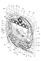
図3及び図4は遊技盤101を示す正面図及び斜視図である。   3 and 4 are a front view and a perspective view showing the game board 101.

図3及び図4において、遊技盤101は、合板の前面に樹脂シートを貼り付けた構造の遊技板300に中央役物2等の各種所物や遊技釘303を配置したものである。
遊技盤101の遊技領域103の中央には、中央役物2が設けられている。
3 and 4, the game board 101 has a game board 300 having a structure in which a resin sheet is pasted on the front surface of a plywood, and various places such as the central accessory 2 and game nails 303 are arranged.
In the center of the game area 103 of the game board 101, a central bonus 2 is provided.

中央役物2は、前記遊技領域103の中央に設けられ、開口部22が形成された枠部材21を主要構成とする前側ユニット3を有し、当該開口部22の背面側に図柄表示部104が配置されている。図柄表示部104の開口部22から露出する部分は、画面400となっている。枠部材21の表面には、金色の鍍金が施されている。   The central accessory 2 is provided at the center of the game area 103 and has a front unit 3 mainly composed of a frame member 21 in which an opening 22 is formed, and a symbol display unit 104 on the back side of the opening 22. Is arranged. A portion exposed from the opening 22 of the symbol display unit 104 is a screen 400. On the surface of the frame member 21, a gold plating is applied.

中央役物2の枠部材21の上側中央の若干左寄りには、曲面部23が設けられており、遊技領域103は、この曲面部23から左右に分岐して左打ち用の遊技領域301と勢いが付きすぎた遊技球を減速させて回収口108に導く線路302に分けられている。   A curved surface portion 23 is provided slightly to the left of the upper center of the frame member 21 of the central accessory 2, and the game area 103 branches from the curved surface section 23 to the left and right and gains momentum from the left-handed game area 301. It is divided into the track | truck 302 which decelerates the game ball to which too much was attached, and guides it to the collection port 108.

左打ち用の遊技領域301には、多数本の遊技釘303とともに、入賞ゲート106、普通入賞口107a、107b、107c、風車109、第1始動口105、第2始動口120、大入賞口ユニット9等が配置されている。   In the left-handed game area 301, there are a large number of game nails 303, a winning gate 106, ordinary winning holes 107a, 107b, 107c, a windmill 109, a first starting opening 105, a second starting opening 120, and a big winning opening unit. 9 etc. are arranged.

一方、枠部材21の左側壁31には、左打ち用の遊技領域301を落下する遊技球が付近の遊技釘303の誘導により比較的低い確率で突入するワープ経路32が設けられている。   On the other hand, the left side wall 31 of the frame member 21 is provided with a warp path 32 through which a game ball falling in the left-handed game area 301 enters with a relatively low probability by the guidance of a nearby game nail 303.

枠部材21の下壁33の上面には、ワープ経路32を通過した遊技球が転がるステージ面34が形成されている。ステージ面34の中央には遊技球を第1始動口105に誘導する誘導孔35の入り口35a(図4参照)が設けられている。誘導孔35の出口35bは、第1始動口105の上方に位置する。ステージ面34の手前には、ステージ面34から転落した遊技球が転がるステージ面36が形成されている。ステージ面36の中央には、遊技球を第1始動口105に誘導する誘導溝37が形成されている。
下壁33のステージ面34より奥側には建物や雲をイメージする装飾用の飾り401が形成される。飾り401の右側部と画面400の間には、演出役物117が設けられている。
On the upper surface of the lower wall 33 of the frame member 21, a stage surface 34 on which the game ball that has passed through the warp path 32 rolls is formed. In the center of the stage surface 34, an entrance 35a (see FIG. 4) of a guide hole 35 that guides the game ball to the first starting port 105 is provided. The outlet 35 b of the guide hole 35 is located above the first starting port 105. In front of the stage surface 34, a stage surface 36 is formed on which the game ball that has fallen from the stage surface 34 rolls. In the center of the stage surface 36, a guide groove 37 for guiding the game ball to the first starting port 105 is formed.
On the back side of the stage surface 34 of the lower wall 33, a decorative ornament 401 that images a building or a cloud is formed. Between the right side of the decoration 401 and the screen 400, a stage effect 117 is provided.

枠部材21の左側壁31、下壁33、右側壁38、上壁39により囲まれる領域は、上述の開口部22となっている。   A region surrounded by the left side wall 31, the lower wall 33, the right side wall 38, and the upper wall 39 of the frame member 21 is the above-described opening 22.

遊技球は、通常の遊技状態で、曲面部23よりも左下側に落下して左打ち用の遊技領域301に導かれ、遊技釘303や風車109に衝突しながら、あるものは、ワープ経路32、ステージ面34及び誘導孔35を通過し第1始動口105に落下し、また、あるものは、ステージ面36及び誘導溝37を通過し第1始動口105に落下し、また、あるものは、ワープ経路32を介さず直接下方に落下し、普通入賞口107a、107b、107cまたは第1始動口105に入賞し、また、あるものは、アウト球として回収口108に集合し、アウト球通路孔を通って遊技盤3の裏面側に排出される。   In a normal gaming state, the game ball falls to the lower left side with respect to the curved surface portion 23 and is guided to the left-handed game area 301, and while hitting the game nail 303 and the windmill 109, there is a warp path 32. , Passing through the stage surface 34 and the guide hole 35 and falling to the first start port 105, and some passing through the stage surface 36 and the guide groove 37 and falling to the first start port 105, and some , It falls directly downward without going through the warp path 32 and wins the normal winning ports 107a, 107b, 107c or the first starting port 105, and some collects at the recovery port 108 as an out ball, and the out ball path It is discharged to the back side of the game board 3 through the hole.

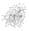
図5は図4に示した演出役物117の分解斜視図である。図6は第1の係合回動部材508及びその周辺部の斜視図である。図7は第2の係合回動部材512の斜視図である。   FIG. 5 is an exploded perspective view of the production actor 117 shown in FIG. FIG. 6 is a perspective view of the first engaging rotation member 508 and its peripheral part. FIG. 7 is a perspective view of the second engaging rotation member 512.

図5において、演出役物117は、ケース本体501と、蓋体502と、モータ駆動ユニット503と、ギア504、505、506と、フォトセンサ507と、第1の係合回動部材508と、ねじりバネ509と、可動部510と、板カム511と、第2の係合回動部材512と、ネジ513、514、515、516、517、518とから構成されている。   In FIG. 5, the production actor 117 includes a case main body 501, a lid 502, a motor drive unit 503, gears 504, 505, 506, a photo sensor 507, a first engagement rotation member 508, The torsion spring 509, the movable portion 510, the plate cam 511, the second engagement rotating member 512, and screws 513, 514, 515, 516, 517 and 518 are included.

可動部510は、係合板521と、取り付け板522と、装飾部本体523と、回動装飾部材524と、ねじりバネ525と、ネジ526、527、528と、ワッシャ529、530とから構成されている。   The movable portion 510 includes an engaging plate 521, a mounting plate 522, a decorative portion main body 523, a rotating decorative member 524, a torsion spring 525, screws 526, 527 and 528, and washers 529 and 530. Yes.

モータ駆動ユニット503は、ケース531にステッピングモータと減速ギアを収納し、回転軸532を回転可能な状態で設けたものである。このステッピングモータの駆動力は、減速ギアを介して回転軸532に伝達され、回転軸532を回転駆動するようになっている。ケース531の先端面側には、一対のネジ止部533、534が設けられている。ケース531の基端側には、副制御基板202に接続されるコネクタ535が設けられている。ネジ止部533、534は、ネジ513、514によりケース本体501の前側板状部541の前面の左側部にネジ止め固定される。   The motor drive unit 503 has a case 531 in which a stepping motor and a reduction gear are housed and a rotating shaft 532 is provided in a rotatable state. The driving force of the stepping motor is transmitted to the rotating shaft 532 via the reduction gear, and the rotating shaft 532 is driven to rotate. A pair of screwing portions 533 and 534 are provided on the tip surface side of the case 531. A connector 535 connected to the sub control board 202 is provided on the base end side of the case 531. The screw fixing portions 533 and 534 are fixed to the left side portion of the front surface of the front plate portion 541 of the case main body 501 by screws 513 and 514.

ケース本体501の前側板状部541の後面は、上側水平板状部542、左上側垂直板状部543、左上側傾斜板状部544、左中間垂直板状部545、左下側水平板状部546、左下側傾斜板状部547及び右下側傾斜板状部548により囲まれることで、収納部520を形成している。   The rear surface of the front plate portion 541 of the case body 501 is an upper horizontal plate portion 542, a left upper vertical plate portion 543, a left upper inclined plate portion 544, a left middle vertical plate portion 545, and a lower left horizontal plate portion. The storage portion 520 is formed by being surrounded by 546, the lower left inclined plate portion 547 and the lower right inclined plate portion 548.

収納部520には、ギア504、505、506、フォトセンサ507、第1及び第2の係合回動部材508、512、ねじりバネ509、可動部510の係合板521及びネジ526、527が収納される。   The storage unit 520 stores gears 504, 505, 506, a photo sensor 507, first and second engagement rotating members 508, 512, a torsion spring 509, an engagement plate 521 of the movable unit 510 and screws 526, 527. Is done.

前側板状部541の後面には、ネジ止め用の突起部551、552、553が後方に突出して設けられる。   On the rear surface of the front plate-like portion 541, screw fixing projections 551, 552, and 553 are provided so as to protrude rearward.

前側板状部541の左端近傍には、モータ駆動ユニット503の回転軸532が回転可能な状態で挿入される貫通孔561が形成されている。前側板状部541の後面における貫通孔561の右側には、軸受け部562が設けられている。軸受け部562には、シャフト563の一端側が回転可能な状態で挿入される。前側板状部541の後面における軸受け部562の右斜め下側には、軸受け部564が設けられている。軸受け部564には、シャフト565の一端側が回転可能な状態で挿入される。前側板状部541の後面における軸受け部564の右斜め上側には、軸取付固定部566が設けられている。軸取付固定部566には、シャフト567の一端側が取り付け固定される。前側板状部541の後面における軸取付固定部566の右斜め上側には、軸受け部568が設けられている。軸受け部568には、シャフト569の一端側が回転可能な状態で挿入される。前側板状部541の後面の中央部には、ねじりバネ509の一端側が係止される突起部570が設けられている。   A through hole 561 is formed in the vicinity of the left end of the front plate-like portion 541 so that the rotating shaft 532 of the motor drive unit 503 can be rotated. A bearing portion 562 is provided on the right side of the through hole 561 on the rear surface of the front plate-like portion 541. One end side of the shaft 563 is inserted into the bearing portion 562 in a rotatable state. A bearing portion 564 is provided on the rear surface of the front plate-shaped portion 541 on the lower right side of the bearing portion 562. One end of the shaft 565 is inserted into the bearing 564 in a rotatable state. A shaft mounting fixing portion 566 is provided on the rear surface of the front plate-like portion 541 on the diagonally upper right side of the bearing portion 564. One end side of the shaft 567 is attached and fixed to the shaft attachment fixing portion 566. A bearing portion 568 is provided on the rear surface of the front plate-like portion 541 on the diagonally upper right side of the shaft mounting fixing portion 566. One end side of the shaft 569 is inserted into the bearing portion 568 in a rotatable state. A projection 570 that engages one end of the torsion spring 509 is provided at the center of the rear surface of the front plate-like portion 541.

前側板状部541の左端近傍には、二時の方向に延びる上下二本のスリット571、572が平行に並べて形成されている。   In the vicinity of the left end of the front plate-like portion 541, two upper and lower slits 571 and 572 extending in the two o'clock direction are formed in parallel.

前側板状部541の上辺近傍の右側寄りには、回動装飾部材524の後述の突起部643が挿通されるスリット573が形成されている。水平板状部542には、スリット573と連通して突起部543と第2の係合回動部材512の先端が挿通されるスリット574が形成されている。一方、水平板状部546及び傾斜板状部547には、ギア506及び板カム511の外周の一部が挿入される貫通部701、702がそれぞれ形成されている。   A slit 573 into which a later-described protrusion 643 of the rotating decorative member 524 is inserted is formed on the right side near the upper side of the front plate-like portion 541. The horizontal plate-like portion 542 is formed with a slit 574 that communicates with the slit 573 and through which the protrusion 543 and the tip of the second engaging rotation member 512 are inserted. On the other hand, the horizontal plate-like portion 546 and the inclined plate-like portion 547 are formed with through portions 701 and 702 into which a part of the outer periphery of the gear 506 and the plate cam 511 is inserted, respectively.

左上側垂直板状部543及び左下側傾斜板状部547には、中央役物2(図3参照)に取り付け固定するためのネジ止部703、704が外側に突出してそれぞれ設けられている。   The upper left vertical plate-like portion 543 and the lower left inclined plate-like portion 547 are provided with screwing portions 703 and 704 for attaching and fixing to the central accessory 2 (see FIG. 3), respectively.

ギア504の中心の貫通孔575には、貫通孔561から突出するモータ駆動ユニット503の回転軸532が嵌入される。これにより、ギア504は、回転軸532に取り付け固定される。ここで貫通孔575及び回転軸532の貫通孔575に嵌入される部分は断面がD字形状に形成され、回転軸532とギア504の間では非回転の状態になる。   The rotation shaft 532 of the motor drive unit 503 protruding from the through hole 561 is fitted into the through hole 575 at the center of the gear 504. Thereby, the gear 504 is attached and fixed to the rotating shaft 532. Here, the portions of the through hole 575 and the rotation shaft 532 that are fitted into the through hole 575 have a D-shaped cross section, and the rotation shaft 532 and the gear 504 are not rotated.

ギア505は、中心の貫通孔576にシャフト563が挿入されることで、シャフト563に取り付けられる。ギア505は、ギア504より大径に形成されている。   The gear 505 is attached to the shaft 563 by inserting the shaft 563 into the central through hole 576. The gear 505 has a larger diameter than the gear 504.

ギア506は、中心の貫通孔580にシャフト565が挿入されることで、シャフト565に取り付けられる。ギア506は、ギア505より大径に形成されている。ギア506の後面の外周近傍には、第1の係合回動部材508と係合する凹形状の溝カム581が形成されている。溝カム581は、後側から見て楕円形状になっており、さらに貫通孔580の中心に対して偏心した形状になっている。
ギア506の後面の貫通孔580から半径の1/3程度離れた位置には、リング状の壁部582が形成されている。壁部582には一本のスリット583が前後方向に形成されている。壁部582の前後の中間部には板カム511と嵌合する溝部584が形成されている。
The gear 506 is attached to the shaft 565 by inserting the shaft 565 into the central through hole 580. The gear 506 has a larger diameter than the gear 505. A concave groove cam 581 that engages with the first engagement rotating member 508 is formed in the vicinity of the outer periphery of the rear surface of the gear 506. The groove cam 581 has an elliptical shape when viewed from the rear side, and is further eccentric with respect to the center of the through hole 580.
A ring-shaped wall 582 is formed at a position separated from the through hole 580 on the rear surface of the gear 506 by about 1/3 of the radius. A single slit 583 is formed in the wall portion 582 in the front-rear direction. A groove portion 584 that fits with the plate cam 511 is formed in an intermediate portion before and after the wall portion 582.

図5及び図6において、第1の係合回動部材508は、リベットを用いたジョイント591を介してギア506側に延びる一端側のアーム592と、ジョイント591を介して係合板521側に延びる他端側のアーム593が互いに回動可能な状態で設けられている。アーム592の先端側には前方に突出する突起部594が設けられている。突起部594は、ギア506の凹形状の溝カム581に係合する。アーム593のジョイント591寄りの中間部には、貫通孔595が形成され、アーム592の先端側には前方に突出する突起部596が設けられている。アーム593の後面の貫通孔595の回りには、筒状部597が形成されている。
アーム593は、貫通孔595にシャフト567が挿通され、貫通孔595から突出するシャフト567の突出部に形成された溝にスナップリング658が取り付けられている。このような構造により、アーム593は、シャフト567に回転可能な状態で取り付けられる。
シャフト567の軸取付固定部566側には、ねじりバネ509のコイル部が取り付けられている。
ねじりバネ509の一端側は、突起部570に係止され、ねじりバネ509の他端側は、アーム593の右下側に係止する。ねじりバネ509は、アーム59を前方から見て時計回り方向に付勢する。アーム593の突起部596は、係合板521のスリット610に挿入される。
5 and 6, the first engaging rotation member 508 extends to the engagement plate 521 side via the joint 591 and the arm 592 on one end side extending to the gear 506 side via the joint 591 using rivets. The arms 593 on the other end side are provided so as to be rotatable relative to each other. A protruding portion 594 protruding forward is provided on the distal end side of the arm 592. The protrusion 594 engages with the concave groove cam 581 of the gear 506. A through hole 595 is formed in an intermediate portion of the arm 593 near the joint 591, and a protrusion 596 protruding forward is provided on the distal end side of the arm 592. A cylindrical portion 597 is formed around the through hole 595 on the rear surface of the arm 593.
In the arm 593, the shaft 567 is inserted into the through hole 595, and a snap ring 658 is attached to a groove formed in the protruding portion of the shaft 567 protruding from the through hole 595. With such a structure, the arm 593 is attached to the shaft 567 in a rotatable state.
A coil portion of a torsion spring 509 is attached to the shaft attachment fixing portion 566 side of the shaft 567.
One end side of the torsion spring 509 is locked to the protrusion 570, and the other end side of the torsion spring 509 is locked to the lower right side of the arm 593. The torsion spring 509 biases the arm 59 in the clockwise direction when viewed from the front. The protrusion 596 of the arm 593 is inserted into the slit 610 of the engagement plate 521.

一方、図5において、係合板521は、金属により板状に形成されたものであり、長四角形状に形成されるとともに、長四角形状の水平板状部542側のコーナーが水平板状部542と略並行になるようにカットされた形状になっている。係合板521には、スリット610とネジ挿通孔611、612が形成されている。ネジ挿通孔611、612は、係合板521の右下側傾斜板状部548側のコーナー近傍に形成されている。スリット610は、係合板521の上下の中間から若干上側の位置においてスリット571、572に対して垂直になる方向に形成されている。   On the other hand, in FIG. 5, the engagement plate 521 is formed in a plate shape from metal, is formed in a long square shape, and the corner on the horizontal plate portion 542 side of the long square shape is the horizontal plate portion 542. It has a shape that is cut so that it is almost parallel. A slit 610 and screw insertion holes 611 and 612 are formed in the engagement plate 521. The screw insertion holes 611 and 612 are formed in the vicinity of the corner on the lower right inclined plate-like portion 548 side of the engagement plate 521. The slit 610 is formed in a direction perpendicular to the slits 571 and 572 at a position slightly above the middle between the upper and lower sides of the engagement plate 521.

取り付け板522は、金属により長四角形の板状に形成されたものである。取り付け板522には、ネジ挿通孔621、622が形成されている。このネジ挿通孔621、622は、取り付け板522の右下側傾斜板状部548側のコーナー近傍に形成されている。   The attachment plate 522 is formed in a long rectangular plate shape from metal. Screw holes 621 and 622 are formed in the mounting plate 522. The screw insertion holes 621 and 622 are formed in the vicinity of the corner on the lower right inclined plate-like portion 548 side of the mounting plate 522.

取り付け板522の後面には、スリット571に挿入される一対のローラー623、624と、スリット572に挿入される一対のローラー625、626とが設けられている。ローラー623、624、625、626は、スリット571、572に対する取り付け板522の移動を滑らかにするためのものである。   A rear surface of the mounting plate 522 is provided with a pair of rollers 623 and 624 inserted into the slit 571 and a pair of rollers 625 and 626 inserted into the slit 572. The rollers 623, 624, 625, and 626 are for smooth movement of the mounting plate 522 with respect to the slits 571 and 572.

装飾部本体523は、合成樹脂を素材とし金型で一体形成されたものであり、上側が人物をイメージした浮き彫りの形状に形成された装飾部631となり、下側が板状の取り付け部632になっている。取り付け部632には、ネジ526、527のネジ部が螺入されるネジ孔633、634が形成されている。装飾部631の裏側には、金型成形の際のヒケを防止するために凹形状に形成されている。装飾部本体523の右側には貫通孔635と円周形状のスリット636、638が形成されている。スリット638は、スリット636より貫通孔635から離れた位置に形成される。   The decorative portion main body 523 is integrally formed with a mold made of synthetic resin. The decorative portion main body 523 is a decorative portion 631 formed in a relief shape in the image of a person on the upper side, and a plate-shaped attachment portion 632 on the lower side. ing. The attachment portion 632 is formed with screw holes 633 and 634 into which the screw portions of the screws 526 and 527 are screwed. On the back side of the decorative portion 631, a concave shape is formed in order to prevent sink marks during molding. A through hole 635 and circumferential slits 636 and 638 are formed on the right side of the decorative body 523. The slit 638 is formed at a position farther from the through hole 635 than the slit 636.

回動装飾部材524はタオルとそれを握る手をイメージした浮き彫りの形状に形成された装飾部になっている。回動装飾部材524の裏側には、金型成形の際のヒケを防止するために凹形状に形成されている。回動装飾部材524の基端側の後面には貫通孔635に挿入される突起部641と円周状のスリット636に挿入される係止部642と円周状のスリット638に挿入される突起部643が形成されている。突起部641は、回動装飾部材524の重心から外れた位置に設けられた回動軸になっている。突起部643は、係止部642より突起部641から離れた位置に形成される。   The rotating decorative member 524 is a decorative part formed in a relief shape in the image of a towel and a hand holding it. On the back side of the rotating decorative member 524, a concave shape is formed in order to prevent sink marks during molding. On the rear surface on the proximal end side of the rotating decorative member 524, a protrusion 641 inserted into the through hole 635, a locking part 642 inserted into the circumferential slit 636, and a protrusion inserted into the circumferential slit 638. A portion 643 is formed. The protrusion 641 is a rotation shaft provided at a position deviating from the center of gravity of the rotation decorative member 524. The protruding portion 643 is formed at a position farther from the protruding portion 641 than the locking portion 642.

また、突起部641には、ネジ孔が形成されている。突起部641は、装飾部本体523の前側から貫通孔635に挿入され、貫通孔635から装飾部本体523の後側に突出した部分にねじりバネ525のコイル部が取り付けられた状態で、ネジ528のネジ部が突起部641のネジ孔に螺入して締め付けられる。これにより、ネジ528のネジ頭と装飾部本体523の後面の間にはねじりバネ525のコイル部が挟まれ、ねじりバネ525の脱落が防止されるとともに、装飾部本体523に回動装飾部材524が回動可能な状態で設けられている。ねじりバネ525の一端側は、装飾部本体523の後ろ側の枠部637の内側に係止し、ねじりバネ525の他端側は、円周状のスリット636から後方に突出する係止部642に右側から係止する。これにより、ねじりバネ525は、回動装飾部材524を前方から見て時計回り方向に付勢している。通常時、回動装飾部材524の係止部642は、装飾部本体523の円周状のスリット636の時計回り方向の端部に当接して停止した状態になり、回動装飾部材524の先端が下方を向いた状態になる。   The protrusion 641 is formed with a screw hole. The protrusion 641 is inserted into the through-hole 635 from the front side of the decorative portion main body 523, and the coil 528 of the torsion spring 525 is attached to a portion protruding from the through-hole 635 to the rear side of the decorative portion main body 523. Are screwed into the screw holes of the protrusions 641 and tightened. As a result, the coil portion of the torsion spring 525 is sandwiched between the screw head of the screw 528 and the rear surface of the decoration portion main body 523 to prevent the torsion spring 525 from falling off, and the decorative portion main body 523 has a rotating decoration member 524. Is provided in a rotatable state. One end side of the torsion spring 525 is engaged with the inner side of the frame portion 637 on the rear side of the decorative portion main body 523, and the other end side of the torsion spring 525 is engaged with the engagement portion 642 protruding rearward from the circumferential slit 636. Lock from the right side. Thereby, the torsion spring 525 urges the rotating decorative member 524 in the clockwise direction when viewed from the front. Normally, the locking portion 642 of the rotating decorative member 524 comes into contact with and stops at the end of the circumferential slit 636 of the decorative portion main body 523 in the clockwise direction, and the tip of the rotating decorative member 524 is stopped. Will face down.

ワッシャ529、530は、スリット571に挿入可能であるとともに、前側板状部541の厚みよりも僅かに厚く形成されている。   The washers 529 and 530 can be inserted into the slit 571 and are formed slightly thicker than the thickness of the front plate portion 541.

ワッシャ529、530及び取り付け板522の一対のローラー623、624をスリット571に挿入し、取り付け板522のローラー625、626をスリット572に挿入した状態において、ネジ526、527は、ネジ部がそれぞれ係合板521のネジ挿通孔611、612に挿通し、それぞれワッシャ529、530の輪の内側に挿通し、それぞれ取り付け板522のネジ挿通孔621、622に挿通し、装飾部本体523のネジ孔633、634に螺入して締め付けられることで可動部510をスリット571、572に沿ってスライド可能な状態でケース本体501に取り付けている。
板カム511は、合成樹脂を円盤状に形成したものであり、中心にギア506の壁部582が挿入されて溝部584と嵌合する貫通孔711が形成されている。尚、壁部582のスリット583は、ギア506の壁部582が貫通孔711に挿入される際に弾性変形を容易にする機能も有している。
貫通孔711の内周の一部に凹部712が形成され、溝部584の一部には、凸部585が形成されており、凹部712と凸部585が嵌合することで、板カム511がギア506に対して非回転の状態で固定される。
板カム511の後面の貫通孔711の周りには、後方に突出する段部がカム部713として形成されている。カム部713は、後側から見て楕円形状になっており、さらに貫通孔711の中心に対して偏心した形状になっている。
図5及び図7において、第2の係合回動部材512は、結合部721を介してカム部713側に延びる一端側のアーム722と、先端側が回動装飾部材524の突起部643側に延びる他端側のアーム723が互いにスライド可能な状態で設けられている。アーム722側の結合部721には、貫通孔724が形成されている。アーム722は、貫通孔724にシャフト569が挿入されることで、シャフト569に取り付けられる。他端側のアーム723の前端には、左上側から突起部643を係合可能なフック725が形成されている。
結合部721について以下に詳細に形成する。結合部721は、アーム722の他端側にアーム722の長手方向から25°程度上方に傾斜して設けられた板状部726と左右のリベット727、728が設けられている。一方、他端側のアーム723には、長手方向に延びるスリット729が形成されている。左右のリベット727、728は、軸部がアーム723のスリット729に挿入された状態で板状部726に固定される。アーム723のスリット729の縁部は、リベット727、728のリベット頭と板状部726の間に挟まれる。これにより、アーム723は結合部721に対してスライド可能な状態で設けられる。板状部726のリベット727、728を固定した位置の中間には、貫通孔724が形成されている。貫通孔724、スリット729により後方に露出する。
In a state where the pair of rollers 623 and 624 of the washers 529 and 530 and the mounting plate 522 are inserted into the slit 571 and the rollers 625 and 626 of the mounting plate 522 are inserted into the slit 572, the screws 526 and 527 are respectively associated with the screw portions. Inserted into the screw insertion holes 611 and 612 of the plywood plate 521, inserted into the inside of the rings of the washers 529 and 530, respectively, inserted into the screw insertion holes 621 and 622 of the attachment plate 522, and screw holes 633 of the decorative body 523, The movable portion 510 is attached to the case main body 501 so as to be slidable along the slits 571 and 572 by being screwed into the 634 and tightened.
The plate cam 511 is formed of a synthetic resin in a disc shape, and a wall portion 582 of the gear 506 is inserted in the center, and a through hole 711 that fits into the groove portion 584 is formed. The slit 583 of the wall portion 582 also has a function of facilitating elastic deformation when the wall portion 582 of the gear 506 is inserted into the through hole 711.
A concave portion 712 is formed in a part of the inner periphery of the through hole 711, and a convex portion 585 is formed in a part of the groove portion 584. By fitting the concave portion 712 and the convex portion 585, the plate cam 511 is Fixed to the gear 506 in a non-rotating state.
Around the through hole 711 on the rear surface of the plate cam 511, a step portion protruding rearward is formed as a cam portion 713. The cam portion 713 has an elliptical shape when viewed from the rear side, and is further eccentric with respect to the center of the through hole 711.
5 and 7, the second engaging rotation member 512 includes an arm 722 on one end side that extends toward the cam portion 713 via the coupling portion 721 and a protruding portion 643 side of the rotation decoration member 524 on the distal end side. The extending arm 723 on the other end side is provided so as to be slidable with respect to each other. A through hole 724 is formed in the coupling portion 721 on the arm 722 side. The arm 722 is attached to the shaft 569 by inserting the shaft 569 into the through hole 724. At the front end of the arm 723 on the other end side, a hook 725 that can engage the protrusion 643 from the upper left side is formed.
The coupling portion 721 is formed in detail below. The coupling portion 721 is provided with a plate-like portion 726 and left and right rivets 727 and 728 provided on the other end side of the arm 722 so as to be inclined upward by about 25 ° from the longitudinal direction of the arm 722. On the other hand, a slit 729 extending in the longitudinal direction is formed in the arm 723 on the other end side. The left and right rivets 727 and 728 are fixed to the plate-like portion 726 in a state where the shaft portion is inserted into the slit 729 of the arm 723. The edge portion of the slit 729 of the arm 723 is sandwiched between the rivet heads of the rivets 727 and 728 and the plate-like portion 726. As a result, the arm 723 is provided in a slidable state with respect to the coupling portion 721. A through hole 724 is formed in the middle of the position where the rivets 727 and 728 of the plate-like portion 726 are fixed. It is exposed rearward by the through hole 724 and the slit 729.

図5において、蓋体502には、ネジ516、517、518のネジ部が挿通されるネジ挿通孔651、652、653と、フォトセンサ507を取り付ける取り付け部655と、ギア505、506及び第1の係合回動部材508を取り付けたシャフト563、565、569の他端側の軸受けを行う軸受け部656、657、659とが設けられている。   In FIG. 5, the lid 502 has screw insertion holes 651, 652, and 653 through which the screw portions of screws 516, 517, and 518 are inserted, a mounting portion 655 to which the photosensor 507 is attached, gears 505 and 506, and a first one. Are provided with bearing portions 656, 657, and 659 for bearings on the other end side of the shafts 563, 565, and 569 to which the engaging rotation member 508 is attached.

取り付け部655は、後面側に膨出した形状に形成され、膨出した形状の前面側に形成される凹部にフォトセンサ507の後ろ側を収納するようになっている。取り付け部655の中央には、ネジ515のネジ部が挿通されるネジ挿通孔661が形成されている。取り付け部655の左横には、フォトセンサ507のコネクタ671を露出するための貫通部662が形成されている。フォトセンサ507には、ネジ孔672が形成されている。ネジ515は、ネジ部が蓋体502の後側からネジ挿通孔661に挿通し、フォトセンサ507のネジ孔672に螺入して締め付けられることで、取り付け部655の凹部にネジ止め固定される。   The attachment portion 655 is formed in a shape that bulges to the rear surface side, and the rear side of the photosensor 507 is accommodated in a recess formed on the front surface side of the bulge shape. A screw insertion hole 661 through which the screw portion of the screw 515 is inserted is formed in the center of the attachment portion 655. A through portion 662 for exposing the connector 671 of the photosensor 507 is formed on the left side of the attachment portion 655. A screw hole 672 is formed in the photosensor 507. The screw 515 is screwed and fixed to the concave portion of the attachment portion 655 by inserting the screw portion into the screw insertion hole 661 from the rear side of the lid 502 and screwing into the screw hole 672 of the photosensor 507. .

フォトセンサ507は、発光部673と受光部674を備え、発光部673と受光部674の間にギア506の壁部582を挟み、壁部582のスリット583を検出するようになっている。   The photosensor 507 includes a light emitting portion 673 and a light receiving portion 674, and a wall portion 582 of the gear 506 is sandwiched between the light emitting portion 673 and the light receiving portion 674 so as to detect the slit 583 of the wall portion 582.

ネジ516、517、518は、ネジ部が蓋体502の外側からネジ挿通孔651、652、653に挿通し、ネジ止め用の突起部551、552、553のネジ孔に螺入して締め付けられることで、図8に示すように蓋体502をケース本体501に取り付け固定し、ケース本体501の収納部520を閉塞するようになっている。   The screws 516, 517, and 518 are screwed into the screw insertion holes 651, 652, and 653 from the outside of the lid body 502 and screwed into the screw holes of the screw fixing projections 551, 552, and 553, and tightened. Thus, as shown in FIG. 8, the lid 502 is attached and fixed to the case main body 501, and the storage portion 520 of the case main body 501 is closed.

図8は図5に示した演出役物117の組み立てた状態の後方右斜め上側から見た斜視図である。   FIG. 8 is a perspective view as seen from the diagonally upper right side in the assembled state of the production accessory 117 shown in FIG.

図8において、演出役物117の組み立てた状態では、ケース本体501と蓋体502は、ネジ516、517、518によりネジ止め固定され、一体の箱体になっている。蓋体502の貫通部662からはフォトセンサ507のコネクタ671が露出する。これにより、コネクタ671には、副制御基板202に接続したハーネスのコネクタが接続可能になっている。   In FIG. 8, in the assembled state of the production actor 117, the case main body 501 and the lid 502 are fixed by screws with screws 516, 517, 518 to form an integral box. The connector 671 of the photosensor 507 is exposed from the through portion 662 of the lid 502. Thereby, the connector of the harness connected to the sub-control board 202 can be connected to the connector 671.

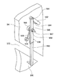
図9は図5に示した演出役物117の組み立てた状態の前方右斜め上側から見た斜視図である。   FIG. 9 is a perspective view as seen from the diagonally upper front side in the assembled state of the effect actor 117 shown in FIG.

図9において、演出役物117の組み立てた状態では、ケース本体501の前面左側には、モータ駆動ユニット503がネジ止め固定され、ケース本体501の前面右側には、可動部510の装飾部本体523がスリット571、572に沿って二時の方向にスライド可能になっている。   In FIG. 9, in the assembled state of the production role 117, the motor drive unit 503 is screwed and fixed to the left side of the front surface of the case main body 501, and the decorative portion main body 523 of the movable portion 510 is fixed to the right side of the front surface of the case main body 501. Is slidable in the 2 o'clock direction along the slits 571 and 572.

図10は図8に示した演出役物117の蓋体502とネジ515、516、517、518を透明にした状態で示す斜視図である。   FIG. 10 is a perspective view showing the lid 502 and the screws 515, 516, 517, and 518 of the director 117 shown in FIG. 8 in a transparent state.

図10において、ケース本体501の収納部520には、ギア504、505、506、板カム511が回転可能な状態で設けられ、第1及び第2の係合回動部材508、512が回動可能な状態で設けられている。ギア504は、モータ駆動ユニット503によって回転駆動される。ギア504は、ギア505と噛み合い、さらにギア505は、ギア506と噛み合う。これにより、ギア504の回転力は、ギア505を介してギア506に伝達し、ギア506及び板カム511が回転駆動するようになっている。第1の係合回動部材508は、ねじりバネ509によって前方から見て反時計回りの方向に付勢される。また、第1の係合回動部材508は、アーム593に設けられた突起部596が係合板521のスリット610に挿入され、一端側のアーム592(図5参照)の突起部594(図5参照)が溝カム581(図5参照)と係合し、ギア506の回転に応じて回動可能になっている。可動部510は、第1の係合回動部材508が前方から見て反時計回り方向に回動した場合、スリット610内で突起部596が摺動しながら突起部596から力が加えられ、スリット571、572に沿ってスライドする。   In FIG. 10, gears 504, 505, 506 and a plate cam 511 are provided in a state in which the housing 520 of the case main body 501 is rotatable, and the first and second engaging rotation members 508, 512 are rotated. It is provided in a possible state. The gear 504 is rotationally driven by the motor drive unit 503. The gear 504 meshes with the gear 505, and the gear 505 meshes with the gear 506. Thereby, the rotational force of the gear 504 is transmitted to the gear 506 through the gear 505, and the gear 506 and the plate cam 511 are rotationally driven. The first engaging rotation member 508 is urged counterclockwise by the torsion spring 509 when viewed from the front. Further, in the first engagement rotating member 508, the protrusion 596 provided on the arm 593 is inserted into the slit 610 of the engagement plate 521, and the protrusion 594 (see FIG. 5) of the arm 592 (see FIG. 5) on one end side. Is engaged with the groove cam 581 (see FIG. 5), and can be rotated according to the rotation of the gear 506. When the first engaging rotation member 508 rotates counterclockwise as viewed from the front, the movable portion 510 is applied with force from the protrusion 596 while the protrusion 596 slides in the slit 610, Slide along the slits 571 and 572.

以下、図11乃至図15を参照して演出役物117の動作を説明する。   Hereinafter, the operation of the production actor 117 will be described with reference to FIGS. 11 to 15.

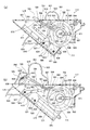
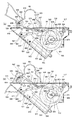
図11(a)は通常時の演出役物117の図9に示したA−A線断面図、図11(b)は可動部510を斜め上方にスライドさせた直後の演出役物117の図9に示したA−A線断面図、図12(a)は通常時の演出役物117の図9に示したB−B線断面図、図12(b)は可動部510を斜め上方にスライドさせた直後の演出役物117の図9に示したB−B線断面図、図13(a)は可動部510を斜め上方にスライドさせ回動装飾部材524を上方に回動させた状態の出役物117の図9に示したB−B線断面図、図13(b)は図13(a)の状態から回動装飾部材524が下側の位置に戻った状態の出役物117の図9に示したB−B線断面図、図14(a)は通常時の演出役物117の正面図、図14(b)は可動部510を斜め上方にスライドさせた直後の演出役物117の正面図、図15(a)は可動部510を斜め上方にスライドさせ回動装飾部材524を上方に回動させた状態の出役物117の正面図、図15(b)は図15(a)の状態から回動装飾部材524を下側の位置に戻った状態の出役物117の正面図である。   FIG. 11A is a cross-sectional view taken along the line AA of FIG. 9 of the effect director 117 in a normal state, and FIG. 11B is a diagram of the effect agent 117 immediately after the movable portion 510 is slid obliquely upward. 9 is a cross-sectional view taken along the line AA shown in FIG. 9, FIG. 12A is a cross-sectional view taken along the line BB shown in FIG. 9 of the normal effector 117, and FIG. FIG. 9 is a cross-sectional view of the effector 117 immediately after sliding, taken along line B-B in FIG. 9, and FIG. 13A shows a state in which the movable portion 510 is slid obliquely upward and the rotating decorative member 524 is rotated upward. FIG. 9 is a cross-sectional view taken along line B-B of FIG. 9 showing the service item 117 of FIG. 13, and FIG. 13B is a service product in a state where the rotating decorative member 524 is returned to the lower position from the state of FIG. 117 is a cross-sectional view taken along the line B-B shown in FIG. 9, FIG. 14A is a front view of the effect director 117 at a normal time, and FIG. FIG. 15 (a) is a front view of the production role 117 immediately after being slid upward, and FIG. 15 (a) is a drawing of the role-playing item 117 in a state in which the movable portion 510 is slid obliquely upward and the rotation decoration member 524 is rotated upward. FIG. 15B is a front view of the actuating object 117 in a state where the rotating decorative member 524 is returned to the lower position from the state of FIG.

図11(a)において、通常時の演出役物117は、ギア506の壁部582のスリット583がフォトセンサ507に検出される位置でギア506の回転が停止した状態になる。この状態で、アーム592の突起部594は、溝カム581の内周の内、ギア506の回転軸から最も離れた位置で係止することになるので、第1の係合回動部材508のアーム592は、バネ509の付勢力により、最も時計回り方向の位置で停止し、突起部596は、最も下方に位置し、可動部510は、スリット571、572に沿って最も下側に位置する。また、通常の状態では回動装飾部材524の先端側は、下方を向いた状態になる。
図12(a)において、通常時では、第2の係合回動部材512の一端側のアーム722は、板カム511のカム部713の外周の内、板カム511の回転軸から最も近い位置で係止することになるので、第2の係合回動部材512は、アーム722に加わる重力により、最も反時計回り方向の位置で停止している。また、他端側のアーム723は、結合部721によりアーム722に対して最も左下方向にスライドした状態になる。
In FIG. 11A, the stage effect 117 at the normal time is in a state where the rotation of the gear 506 is stopped at a position where the slit 583 of the wall portion 582 of the gear 506 is detected by the photosensor 507. In this state, the projection 594 of the arm 592 is locked at a position farthest from the rotation axis of the gear 506 in the inner periphery of the groove cam 581, so that the first engagement rotating member 508 The arm 592 stops at the position in the most clockwise direction by the biasing force of the spring 509, the protrusion 596 is located at the lowest position, and the movable part 510 is located at the lowest side along the slits 571 and 572. . Further, in the normal state, the distal end side of the turning decorative member 524 is directed downward.
In FIG. 12A, the arm 722 on one end side of the second engaging rotation member 512 is normally at a position closest to the rotation axis of the plate cam 511 in the outer periphery of the cam portion 713 of the plate cam 511 in FIG. Therefore, the second engaging rotation member 512 is stopped at the most counterclockwise position due to the gravity applied to the arm 722. In addition, the arm 723 on the other end side is in a state of being slid to the leftmost direction with respect to the arm 722 by the coupling portion 721.

この状態で通常時の演出役物117は、図14(a)に示すように、可動部510の装飾部本体523の装飾部631が高さの70%程度、ケース本体501の上辺の下側に位置し、装飾部631が図4に示す枠部材21の下壁33の飾り401の後ろ側に隠れた状態になる。   In this state, the effect director 117 in the normal state is such that the decorative portion 631 of the decorative portion main body 523 of the movable portion 510 is about 70% of the height, and below the upper side of the case main body 501 as shown in FIG. The decorative portion 631 is hidden behind the ornament 401 on the lower wall 33 of the frame member 21 shown in FIG.

ここで、副制御基板202(図2参照)は、抽選の結果がハズレの際の予告演出中に比較的低い確率で通常時の演出役物117を作動させ、抽選の結果が大当たり際の予告演出中に比較的高い確率で演出役物117を作動させることで大当たりの期待感を高める演出を行っている。また副制御基板202(図2参照)は、図9に示すフォトセンサ507の検出結果よりギア506の回転位置を検出し、モータ駆動ユニット503のステッピングモータの回転の制御を行っている。   Here, the sub-control board 202 (see FIG. 2) activates the effect director 117 at the normal time with a relatively low probability during the notice effect when the lottery result is lost, and the notice of the lottery result is a big hit notice. During the production, the production actor 117 is operated with a relatively high probability, thereby producing an effect that increases the expectation of the jackpot. The sub-control board 202 (see FIG. 2) detects the rotational position of the gear 506 from the detection result of the photosensor 507 shown in FIG. 9, and controls the rotation of the stepping motor of the motor drive unit 503.

副制御基板202は、演出役物117を作動させる場合、モータ駆動ユニット503の回転軸532を回転させ、図11(a)に示す状態からギア506を前方から見て反時計回り(図中A方向)に回動させる。   The sub control board 202 rotates the rotating shaft 532 of the motor drive unit 503 when operating the effect actor 117, and counterclockwise when viewing the gear 506 from the state shown in FIG. ).

これにより、第1の係合回動部材508のアーム592に対するギア506の回転に応じてアーム592の突起部594は、溝カム581の内周を摺動し、摺動する溝カム581の内周の内、ギア506の回転軸から最も離れた位置から近づく位置に移動する。これにより、アーム592が左斜め下方に移動し、アーム593のジョイント591側がアーム592によって左斜め下方に牽引され、第1の係合回動部材508が前方から見て反時計回りに回動し、係合板521により第1の係合回動部材508の突起部596と係合する可動部510も、スリット571、572に沿って図14(a)に示す斜め上方向Bにスライドする。そして可動部510は、図11(b)に示すようにスリット571、572の上側で停止する。この状態で演出役物117は、図14(b)に示すように、可動部510の装飾部本体523の装飾部631が高さの90%程度、ケース本体501の上辺の上側に位置し、装飾部631が図4に示す枠部材21の下壁33の飾り401の後ろ側から画面400の手前側に突出した状態になる。   Accordingly, the projection 594 of the arm 592 slides on the inner periphery of the groove cam 581 in accordance with the rotation of the gear 506 with respect to the arm 592 of the first engaging rotation member 508, and the inner portion of the sliding groove cam 581 is slid. The circumference moves to a position approaching from a position farthest from the rotation axis of the gear 506. As a result, the arm 592 moves diagonally to the left, the joint 591 side of the arm 593 is pulled diagonally to the left by the arm 592, and the first engagement rotation member 508 rotates counterclockwise as viewed from the front. The movable portion 510 that engages with the protrusion 596 of the first engagement rotation member 508 by the engagement plate 521 also slides in the diagonally upward direction B shown in FIG. 14A along the slits 571 and 572. Then, the movable portion 510 stops on the upper side of the slits 571 and 572 as shown in FIG. In this state, as shown in FIG. 14 (b), the director 117 is positioned about 90% of the height of the decorative portion 631 of the decorative portion main body 523 of the movable portion 510 and above the upper side of the case main body 501. The decorative portion 631 is projected from the back side of the decoration 401 on the lower wall 33 of the frame member 21 shown in FIG.

可動部510がスリット571、572に沿って図14(a)に示す斜め上方向Bにスライドすると、回動装飾部材524の突起部643がスリット573に沿って図14(a)に示す斜め上方向Bにスライドし、突起部643が第2の係合回動部材512のフック725と係合して他端側のアーム723を図14(a)に示す斜め上方向Bにスライドさせ、図12(b)に示すように、フック725が突起部643と係合して、他端側のアーム723の先端側から中間部がケース本体501のスリット574から右斜め上方に突出する。
副制御基板202が図12(b)に示す状態からギア506及びこれに固定された板カム511を前方から見て反時計回り(図中A方向)に回動させると、第2の係合回動部材512のアーム722に対する板カム511の回転に応じてアーム722は板カム511のカム部713の外周を摺動し、板カム511の回転軸から最も近づいた位置から最も離れた位置に移動する。これにより、アーム722はカム部713により押し上げられ、第2の係合回動部材512は、前方から見て時計回りに回動し、フック725と係合する突起部643を押し下げるので、係止部642はスリット636の前方から見た逆時計回り方向に移動し、図14(b)に示す回動装飾部材524は突起部641を中心にして前方から見て逆時計回り方向Cに回動し、図13(a)及び図15(a)に示すように回動装飾部材524の先端側は右斜め上を向く。ここで、第2の係合回動部材512が前方から見て時計回りに回動した場合において、他端側のアーム723がアーム722に対してスライドすることで、フック725と突起部643の係合は維持される。
この後、副制御基板202が図13(a)に示す状態からギア506及びこれに固定された板カム511を前方から見て反時計回り(図中A方向)に回動させると、アーム722に摺動するカム部713の外周は、板カム511の回転軸から最も離れた位置から近い位置に移動するので、ねじりバネ525の付勢力により突起部643はフック725を押し上げる。また、第2の係合回動部材512の一端側のアーム722は、板カム511のカム部713の外周の内、板カム511の回転軸から最も近い位置で係止することになるので、第2の係合回動部材512は、図13(b)に示すように最も反時計回り方向の位置で停止している。図15(b)に示すように回動装飾部材524は、ねじりバネ525の付勢力により、前方から見て時計回り方向に回動して先端が下方向を向いた状態に戻る。
この後、副制御基板202は、モータ駆動ユニット503の回転軸532を1秒程度停止させ装飾部631が図4に示す枠部材21の下壁33の後ろ側から画面400の手前側に突出した状態を維持した後、モータ駆動ユニット503の回転軸532を回転させギア506を前方から見て反時計回り(図中A方向)に回動させる。これにより、回動装飾部材524の突起部643がスリット573に沿って図14(a)に示す斜め下向にスライドし、突起部643が第2の係合回動部材512のフック725と係合を解除して図12(a)に示す状態に戻る。
演出役物117は、このような動作を繰り返すことで、可動部510を斜め方向にスライドさせ、回動装飾部材524を回動させる。
When the movable portion 510 slides along the slits 571 and 572 in the diagonally upward direction B shown in FIG. 14A, the protrusion 643 of the rotating decorative member 524 moves diagonally upward along the slit 573 as shown in FIG. Slide in the direction B, and the protrusion 643 engages with the hook 725 of the second engagement rotating member 512 to slide the arm 723 on the other end side in the diagonally upward direction B shown in FIG. As shown in FIG. 12B, the hook 725 engages with the protrusion 643, and the intermediate portion protrudes diagonally upward to the right from the slit 574 of the case body 501 from the distal end side of the arm 723 on the other end side.
When the sub-control board 202 rotates the gear 506 and the plate cam 511 fixed thereto from the state shown in FIG. 12B counterclockwise (A direction in the figure) when viewed from the front, the second engagement In response to the rotation of the plate cam 511 relative to the arm 722 of the rotating member 512, the arm 722 slides on the outer periphery of the cam portion 713 of the plate cam 511 and moves to the position farthest from the position closest to the rotation axis of the plate cam 511. Moving. As a result, the arm 722 is pushed up by the cam portion 713, and the second engagement turning member 512 turns clockwise as viewed from the front, and pushes down the projection 643 that engages with the hook 725. The portion 642 moves in the counterclockwise direction as viewed from the front of the slit 636, and the rotating decorative member 524 shown in FIG. 14B rotates in the counterclockwise direction C as viewed from the front around the protrusion 641. As shown in FIGS. 13A and 15A, the distal end side of the rotating decorative member 524 faces diagonally upward to the right. Here, when the second engagement rotation member 512 is rotated clockwise as viewed from the front, the arm 723 on the other end side slides with respect to the arm 722, so that the hook 725 and the protrusion 643 are connected. Engagement is maintained.
Thereafter, when the sub-control board 202 rotates the gear 506 and the plate cam 511 fixed thereto from the state shown in FIG. 13A counterclockwise (A direction in the figure) when viewed from the front, the arm 722 is rotated. Since the outer periphery of the cam portion 713 that slides in the direction moves from a position farthest away from the rotation axis of the plate cam 511 to a position close thereto, the protrusion 643 pushes up the hook 725 by the urging force of the torsion spring 525. Further, the arm 722 on one end side of the second engagement rotating member 512 is locked at a position closest to the rotation axis of the plate cam 511 in the outer periphery of the cam portion 713 of the plate cam 511. As shown in FIG. 13B, the second engaging rotation member 512 is stopped at the most counterclockwise position. As shown in FIG. 15B, the rotating decorative member 524 is rotated clockwise as viewed from the front by the urging force of the torsion spring 525 and returns to a state where the tip is directed downward.
Thereafter, the sub-control board 202 stops the rotating shaft 532 of the motor drive unit 503 for about 1 second, and the decorative portion 631 protrudes from the rear side of the lower wall 33 of the frame member 21 shown in FIG. After maintaining the state, the rotating shaft 532 of the motor drive unit 503 is rotated to rotate the gear 506 counterclockwise (A direction in the figure) when viewed from the front. As a result, the protrusion 643 of the turning decorative member 524 slides obliquely downward as shown in FIG. 14A along the slit 573, and the protrusion 643 engages with the hook 725 of the second engaging rotation member 512. The combination is canceled and the state shown in FIG.
The effect actor 117 repeats such an operation, thereby sliding the movable portion 510 in an oblique direction and rotating the rotation decoration member 524.

このような構成及び動作を以下に纏めて説明する。   Such a configuration and operation will be described below.

演出役物117は、板状に形成された遊技板300の前面側に遊技球が落下する遊技領域103を有する遊技盤101を備える遊技機1の演出装置になっている。   The stage effect 117 is a stage device of the gaming machine 1 including the game board 101 having the game area 103 where the game ball falls on the front side of the game board 300 formed in a plate shape.

可動部510は、前記遊技板300に対して所定の方向に往復運動可能な状態で設けられている。
回動装飾部材524は、前記可動部510に回動軸である突起部641を中心にして回動可能な状態で設けられている。
ギア506の溝カム581は、回転軸からカム面までの距離が回転角により異なる第1のカムになっている。
板カム511は、溝カム581と回転軸を一致させて前記第1のカム溝カム581に固定され、回転軸からカム面までの距離が回転角により異なる第2のカムになっている。
第1の係合回動部材508は、前記遊技板300に対して回動可能な状態で設けられ第1の部分である突起部576で前記可動部510と摺動可能な状態で係合するとともに、第2の部分である突起部574で前記溝カム581のカム面と摺動可能な状態で係合する。
第2の係合回動部材512は、前記遊技板300に対して回動可能な状態で設けられ第1の部分のフック725で前記回動装飾部材524と係合するとともに、第2の部分であるアーム722で前記板カム511のカム面と摺動可能な状態で係合する。
モータ駆動ユニット503及びギア504、505は、前記溝カム581を回転駆動する回転駆動手段になっている。
前記回転駆動手段は、前記溝カム581を回転駆動することで前記溝カム581とともに前記板カム511を回転させ、当該溝カム581から前記第1の係合回動部材を介して前記可動部510に動力を伝達して当該可動部510に動作を行わせるとともに、前記板カム511を回転させ当該板カム511から前記第2の係合回動部材512を介して前記回動装飾部材524に動力を伝達して当該回動装飾部材524に動作を行わせる。
The movable portion 510 is provided in a state in which the movable portion 510 can reciprocate in a predetermined direction with respect to the game board 300.
The rotating decorative member 524 is provided in the movable portion 510 so as to be rotatable about a protrusion 641 that is a rotating shaft.
The groove cam 581 of the gear 506 is a first cam in which the distance from the rotation shaft to the cam surface differs depending on the rotation angle.
The plate cam 511 is fixed to the first cam groove cam 581 with the groove cam 581 and the rotation axis aligned with each other, and is a second cam in which the distance from the rotation axis to the cam surface varies depending on the rotation angle.
The first engaging rotation member 508 is provided so as to be rotatable with respect to the game board 300, and is engaged with the movable portion 510 in a slidable state with a protrusion 576 serving as a first portion. At the same time, the protrusion 574 as the second portion engages with the cam surface of the groove cam 581 in a slidable state.
The second engagement rotation member 512 is provided in a state of being rotatable with respect to the game board 300 and is engaged with the rotation decoration member 524 by the first portion hook 725 and the second portion. The arm 722 is engaged with the cam surface of the plate cam 511 in a slidable state.
The motor drive unit 503 and the gears 504 and 505 serve as rotational drive means for rotationally driving the groove cam 581.
The rotation driving means rotates the groove cam 581 to rotate the plate cam 511 together with the groove cam 581, and the movable portion 510 via the first engagement rotation member from the groove cam 581. The power is transmitted to the movable portion 510 and the movable portion 510 is operated, and the plate cam 511 is rotated to drive the power from the plate cam 511 to the rotating decorative member 524 via the second engagement rotating member 512. Is transmitted to cause the rotating decorative member 524 to operate.

前記遊技板300には演出用の映像を画面400に表示する映像表示手段としての図柄表示部104を有し、前記可動部510は前記往復運動により前記映像表示手段の画面400の手前側を移動する。   The game board 300 has a symbol display unit 104 as a video display unit for displaying a video for production on the screen 400, and the movable unit 510 moves in front of the screen 400 of the video display unit by the reciprocating motion. To do.

以上に説明した本実施形態によれば、モータ駆動ユニット503及びギア504、505による回転駆動手段が前記溝カム581を回転駆動することで前記溝カム581とともに前記板カム511を回転させ、当該溝カム581から前記第1の係合回動部材を介して前記可動部510に動力を伝達して当該可動部510に動作を行わせるとともに、前記板カム511を回転させ当該板カム511から前記第2の係合回動部材512を介して前記回動装飾部材524に動力を伝達して当該回動装飾部材524に動作を行わせるので、小型かつ低消費電力の駆動手段を用いて演出用の可動部510に複雑な動作を行わせることができ、遊技機の低消費電力化を行えるとともに、製造コストの抑制し、遊技機における演出装置の配置場所の制約を緩和することができる。
尚、図1乃至図15に示した演出役物117は、通常の状態でねじりバネ525の付勢力によって回動装飾部材524の先端側を下方を向いた状態で安定させていたが、ねじりバネ525を設ける代わりに回動装飾部材524の先端側に錘を設け、錘に加わる重力により回動装飾部材524の先端側を下方に向いた状態で安定するように構成してもよい。また、副制御基板202は、モータ駆動ユニット503の回転軸532の回転方向を切り替えたり、さらに断続して回転させることで、可動部510により複雑な動きを行わせることができる。ギア506の溝カム581及び板カム511のカム部713の形状は、楕円形状以外の形状も採用することが可能で、形状を複雑にすることで、可動部510により複雑な動きを行わせることができる。
また、図1乃至図15に示した演出役物117では、前記可動部510に移動可能な状態で設けられた移動装飾部材として回動装飾部材524を用い、前記板カム511を回転させ当該板カム511から前記第2の係合回動部材512を介して前記回動装飾部材524に動力を伝達して当該回動装飾部材524に動作を行わせる構成を用いたが、移動装飾部材としては、可動部に対して直線移動をするものや曲線移動をするもの等、各種適用可能である。
According to the present embodiment described above, the rotation drive means by the motor drive unit 503 and the gears 504 and 505 rotates the groove cam 581 to rotate the plate cam 511 together with the groove cam 581, and the groove Power is transmitted from the cam 581 to the movable portion 510 via the first engaging rotation member to cause the movable portion 510 to operate, and the plate cam 511 is rotated to cause the plate cam 511 to rotate. Power is transmitted to the rotating decorative member 524 via the second engaging rotating member 512 to cause the rotating decorative member 524 to operate, so that a small and low-power driving means is used for production. The movable unit 510 can perform complicated operations, reduce the power consumption of the gaming machine, reduce the manufacturing cost, and ease the restrictions on the location of the rendering device in the gaming machine. It can be.
1 to 15 stabilizes the rotating decorative member 524 with the urging force of the torsion spring 525 in a normal state in a state where the front end side of the turning decorative member 524 faces downward. Instead of providing 525, a weight may be provided on the distal end side of the rotating decorative member 524, and the distal end side of the rotating decorative member 524 may be stabilized while being directed downward by gravity applied to the weight. Further, the sub-control board 202 can cause the movable portion 510 to perform complicated movements by switching the rotation direction of the rotation shaft 532 of the motor drive unit 503 or by intermittently rotating it. The shape of the groove cam 581 of the gear 506 and the shape of the cam portion 713 of the plate cam 511 can also adopt shapes other than an elliptical shape, and by making the shapes complicated, the movable portion 510 can perform complicated movements. Can do.
In addition, in the effect actor 117 shown in FIGS. 1 to 15, a rotating decorative member 524 is used as a movable decorative member provided in a movable state on the movable portion 510, and the plate cam 511 is rotated to rotate the plate. A configuration is used in which power is transmitted from the cam 511 to the rotating decorative member 524 via the second engaging rotating member 512 to cause the rotating decorative member 524 to operate. Various applications such as a linear movement or a curve movement with respect to the movable part can be applied.

1……遊技機、2……中央役物、15……ガラス扉、
101……遊技盤、104……図柄表示部、117……演出役物、
300……遊技板、 400……画面、501……ケース本体、
502……蓋体、503……モータ駆動ユニット、
504、505、506……ギア、507……フォトセンサ、
508……係合回動部材、509……引張りコイルバネ、
510……可動部、523……装飾部本体、524……回動装飾部材、
553……延出部、600……突起部、641……突起部
1 ... Pachislot machine, 2 ... Central character, 15 ... Glass door,
101 …… Game board, 104 …… Pattern display part, 117 …… Director,
300 …… Game board, 400 …… Screen, 501 …… Case body,
502 …… Cover body, 503 …… Motor drive unit,
504, 505, 506 ... Gear, 507 ... Photo sensor,
508... Engaging rotation member, 509... Tension coil spring,
510... Movable part, 523... Decoration part body, 524.
553 ... Extension part, 600 ... Projection part, 641 ... Projection part

Claims (3)

板状に形成された遊技板の前面側に遊技球が落下する遊技領域を有する遊技盤を備える遊技機の演出装置であって、
前記遊技板に対して所定の方向に往復運動可能な状態で設けられた可動部と、
回転軸からカム面までの距離が回転角により異なるカムと、
前記遊技板に対して回動可能な状態で設けられ第1の部分で前記可動部と摺動可能な状態で係合するとともに、第2の部分で前記カムのカム面と摺動可能な状態で係合する係合回動部材と、
前記カムを回転駆動する回転駆動手段とを備え、
前記回転駆動手段が前記カムを回転駆動することで当該カムから係合回動部材を介して前記可動部に動力を伝達して当該可動部に動作を行わせることを特徴とする遊技機の演出装置。
A rendering device of a gaming machine comprising a gaming board having a gaming area where a gaming ball falls on the front side of a gaming board formed in a plate shape,
A movable part provided in a state capable of reciprocating in a predetermined direction with respect to the game board;
A cam whose distance from the rotation axis to the cam surface varies depending on the rotation angle;
Provided in a rotatable state with respect to the game board and engaged with the movable portion in a slidable state at the first portion, and slidable with the cam surface of the cam at the second portion An engaging rotation member to be engaged with,
Rotational drive means for rotationally driving the cam,
An effect of a gaming machine characterized in that the rotational drive means rotationally drives the cam to transmit power from the cam to the movable part via an engaging rotation member to cause the movable part to operate. apparatus.
板状に形成された遊技板の前面側に遊技球が落下する遊技領域を有する遊技盤を備える遊技機の演出装置であって、
前記遊技板に対して所定の方向に往復運動可能な状態で設けられた可動部と、
前記可動部に移動可能な状態で設けられた移動装飾部材と、
回転軸からカム面までの距離が回転角により異なる第1のカムと、
第1のカムと回転軸を一致させて前記第1のカムに固定され、回転軸からカム面までの距離が回転角により異なる第2のカムと、
前記遊技板に対して回動可能な状態で設けられ第1の部分で前記可動部と摺動可能な状態で係合するとともに、第2の部分で前記第1のカムのカム面と摺動可能な状態で係合する第1の係合回動部材と、
前記遊技板に対して回動可能な状態で設けられ第1の部分で前記回動装飾部材と係合するとともに、第2の部分で前記第2のカムのカム面と摺動可能な状態で係合する第2の係合回動部材と、
前記第1のカムを回転駆動する回転駆動手段とを備え、
前記回転駆動手段が前記第1のカムを回転駆動することで前記第1のカムとともに前記第2のカムを回転させ、当該第1のカムから前記第1の係合回動部材を介して前記可動部に動力を伝達して当該可動部に動作を行わせるとともに、前記第2のカムを回転させ当該第2のカムから前記第2の係合回動部材を介して前記移動装飾部材に動力を伝達して当該移動装飾部材に動作を行わせることを特徴とする遊技機の演出装置。
A rendering device of a gaming machine comprising a gaming board having a gaming area where a gaming ball falls on the front side of a gaming board formed in a plate shape,
A movable part provided in a state capable of reciprocating in a predetermined direction with respect to the game board;
A movable decorative member provided in a movable state on the movable part;
A first cam in which the distance from the rotation shaft to the cam surface varies depending on the rotation angle;
A second cam that is fixed to the first cam with the first cam and the rotation axis aligned, and the distance from the rotation axis to the cam surface varies depending on the rotation angle;
It is provided in a rotatable state with respect to the game board, and engages with the movable portion in a slidable state at the first portion, and slides with the cam surface of the first cam at the second portion. A first engaging rotation member that engages in a possible state;
It is provided in a rotatable state with respect to the game board, and engages with the rotating decorative member at the first portion, and is slidable with the cam surface of the second cam at the second portion. A second engaging rotation member to be engaged;
Rotational drive means for rotationally driving the first cam;
The rotational driving means rotationally drives the first cam to rotate the second cam together with the first cam, and from the first cam through the first engagement rotating member, the Power is transmitted to the movable part to cause the movable part to perform an operation, and the second cam is rotated to power the movable decorative member from the second cam via the second engagement rotating member. A game machine rendering device characterized in that the movement decoration member performs an action by transmitting the movement.
前記遊技板には演出用の映像を画面に表示する映像表示手段を有し、前記可動部は前記往復運動により前記映像表示手段の画面の手前側を移動することを特徴とする請求項1または2に記載の遊技機の演出装置。   2. The game board according to claim 1, further comprising video display means for displaying a video for production on a screen, wherein the movable portion moves in front of the screen of the video display means by the reciprocating motion. 2. The game machine effect device according to 2.
JP2009046246A 2009-02-27 2009-02-27 Game machine directing device Expired - Fee Related JP5281925B2 (en)

Priority Applications (1)

Application Number Priority Date Filing Date Title
JP2009046246A JP5281925B2 (en) 2009-02-27 2009-02-27 Game machine directing device

Applications Claiming Priority (1)

Application Number Priority Date Filing Date Title
JP2009046246A JP5281925B2 (en) 2009-02-27 2009-02-27 Game machine directing device

Publications (2)

Publication Number Publication Date
JP2010200790A JP2010200790A (en) 2010-09-16
JP5281925B2 true JP5281925B2 (en) 2013-09-04

Family

ID=42962927

Family Applications (1)

Application Number Title Priority Date Filing Date
JP2009046246A Expired - Fee Related JP5281925B2 (en) 2009-02-27 2009-02-27 Game machine directing device

Country Status (1)

Country Link
JP (1) JP5281925B2 (en)

Families Citing this family (10)

* Cited by examiner, † Cited by third party
Publication number Priority date Publication date Assignee Title
JP5378453B2 (en) * 2011-05-30 2013-12-25 京楽産業.株式会社 Game machine
JP5308478B2 (en) * 2011-05-30 2013-10-09 京楽産業.株式会社 Game machine
JP5181046B2 (en) * 2011-06-28 2013-04-10 株式会社サンセイアールアンドディ Game machine
JP5603389B2 (en) * 2012-08-28 2014-10-08 株式会社ユニバーサルエンターテインメント Game machine
JP5810200B2 (en) * 2014-08-21 2015-11-11 株式会社ユニバーサルエンターテインメント Game machine
JP6439111B2 (en) * 2015-10-30 2018-12-19 株式会社ソフイア Game machine
JP6510994B2 (en) * 2016-02-23 2019-05-08 株式会社ソフイア Gaming machine
JP6196006B2 (en) * 2016-02-29 2017-09-13 K・M・S株式会社 Tilt adjustment system for pachinko machines
JP6511173B2 (en) * 2018-02-02 2019-05-15 株式会社ユニバーサルエンターテインメント Gaming machine
JP6534464B2 (en) * 2018-02-21 2019-06-26 株式会社ユニバーサルエンターテインメント Gaming machine

Family Cites Families (2)

* Cited by examiner, † Cited by third party
Publication number Priority date Publication date Assignee Title
JP4552050B2 (en) * 2005-02-10 2010-09-29 株式会社大一商会 Pachinko machine
JP4912248B2 (en) * 2007-07-27 2012-04-11 タイヨーエレック株式会社 Game machine

Also Published As

Publication number Publication date
JP2010200790A (en) 2010-09-16

Similar Documents

Publication Publication Date Title
JP5281925B2 (en) Game machine directing device
JP5281924B2 (en) Game machine directing device
JP2011115211A (en) Game machine
JP2008245893A (en) Game table
JP5061223B2 (en) Game machine
JP5808452B2 (en) Game machine
JP2011062396A (en) Game machine
JP5346698B2 (en) Big prize opening device
JP2008245892A (en) Game table
JP5508799B2 (en) Game machine
JP5371637B2 (en) Game machine
JP5698901B2 (en) Game machine
JP2010167128A (en) Performance device of game machine
JP5346621B2 (en) Game machine
JP5021799B2 (en) Game machine
JP5739924B2 (en) Game machine
JP2006167171A (en) Game parts for pinball game machine
JP2010125055A (en) Movable accessory mounting structure for game machine
JP4915933B2 (en) Bullet ball machine
JP5810200B2 (en) Game machine
JP5443715B2 (en) Big prize opening device
JP5792873B2 (en) Game machine
JP6639534B2 (en) Gaming machine
JP2010125056A (en) Game board for game machine
JP2011078590A (en) Game machine

Legal Events

Date Code Title Description
RD02 Notification of acceptance of power of attorney

Free format text: JAPANESE INTERMEDIATE CODE: A7422

Effective date: 20101229

A621 Written request for application examination

Free format text: JAPANESE INTERMEDIATE CODE: A621

Effective date: 20120119

TRDD Decision of grant or rejection written
A01 Written decision to grant a patent or to grant a registration (utility model)

Free format text: JAPANESE INTERMEDIATE CODE: A01

Effective date: 20130430

A61 First payment of annual fees (during grant procedure)

Free format text: JAPANESE INTERMEDIATE CODE: A61

Effective date: 20130527

R150 Certificate of patent or registration of utility model

Ref document number: 5281925

Country of ref document: JP

Free format text: JAPANESE INTERMEDIATE CODE: R150

Free format text: JAPANESE INTERMEDIATE CODE: R150

R250 Receipt of annual fees

Free format text: JAPANESE INTERMEDIATE CODE: R250

R250 Receipt of annual fees

Free format text: JAPANESE INTERMEDIATE CODE: R250

LAPS Cancellation because of no payment of annual fees