JP5267671B2 - Magnet handling equipment - Google Patents
Magnet handling equipment Download PDFInfo
- Publication number
- JP5267671B2 JP5267671B2 JP2011524569A JP2011524569A JP5267671B2 JP 5267671 B2 JP5267671 B2 JP 5267671B2 JP 2011524569 A JP2011524569 A JP 2011524569A JP 2011524569 A JP2011524569 A JP 2011524569A JP 5267671 B2 JP5267671 B2 JP 5267671B2
- Authority
- JP
- Japan
- Prior art keywords
- magnet
- cleaving
- divided
- magnets
- divided magnets
- Prior art date
- Legal status (The legal status is an assumption and is not a legal conclusion. Google has not performed a legal analysis and makes no representation as to the accuracy of the status listed.)
- Expired - Fee Related
Links
Images


Classifications
-
- H—ELECTRICITY
- H02—GENERATION; CONVERSION OR DISTRIBUTION OF ELECTRIC POWER
- H02K—DYNAMO-ELECTRIC MACHINES
- H02K15/00—Methods or apparatus specially adapted for manufacturing, assembling, maintaining or repairing of dynamo-electric machines
- H02K15/02—Methods or apparatus specially adapted for manufacturing, assembling, maintaining or repairing of dynamo-electric machines of stator or rotor bodies
- H02K15/03—Methods or apparatus specially adapted for manufacturing, assembling, maintaining or repairing of dynamo-electric machines of stator or rotor bodies having permanent magnets
-
- Y—GENERAL TAGGING OF NEW TECHNOLOGICAL DEVELOPMENTS; GENERAL TAGGING OF CROSS-SECTIONAL TECHNOLOGIES SPANNING OVER SEVERAL SECTIONS OF THE IPC; TECHNICAL SUBJECTS COVERED BY FORMER USPC CROSS-REFERENCE ART COLLECTIONS [XRACs] AND DIGESTS
- Y10—TECHNICAL SUBJECTS COVERED BY FORMER USPC
- Y10T—TECHNICAL SUBJECTS COVERED BY FORMER US CLASSIFICATION
- Y10T156/00—Adhesive bonding and miscellaneous chemical manufacture
- Y10T156/12—Surface bonding means and/or assembly means with cutting, punching, piercing, severing or tearing
- Y10T156/1317—Means feeding plural workpieces to be joined
- Y10T156/1322—Severing before bonding or assembling of parts
-
- Y—GENERAL TAGGING OF NEW TECHNOLOGICAL DEVELOPMENTS; GENERAL TAGGING OF CROSS-SECTIONAL TECHNOLOGIES SPANNING OVER SEVERAL SECTIONS OF THE IPC; TECHNICAL SUBJECTS COVERED BY FORMER USPC CROSS-REFERENCE ART COLLECTIONS [XRACs] AND DIGESTS
- Y10—TECHNICAL SUBJECTS COVERED BY FORMER USPC
- Y10T—TECHNICAL SUBJECTS COVERED BY FORMER US CLASSIFICATION
- Y10T156/00—Adhesive bonding and miscellaneous chemical manufacture
- Y10T156/17—Surface bonding means and/or assemblymeans with work feeding or handling means
- Y10T156/1798—Surface bonding means and/or assemblymeans with work feeding or handling means with liquid adhesive or adhesive activator applying means
-
- Y—GENERAL TAGGING OF NEW TECHNOLOGICAL DEVELOPMENTS; GENERAL TAGGING OF CROSS-SECTIONAL TECHNOLOGIES SPANNING OVER SEVERAL SECTIONS OF THE IPC; TECHNICAL SUBJECTS COVERED BY FORMER USPC CROSS-REFERENCE ART COLLECTIONS [XRACs] AND DIGESTS
- Y10—TECHNICAL SUBJECTS COVERED BY FORMER USPC
- Y10T—TECHNICAL SUBJECTS COVERED BY FORMER US CLASSIFICATION
- Y10T225/00—Severing by tearing or breaking
- Y10T225/30—Breaking or tearing apparatus
Description
本発明は、割断前磁石を割断して得られる複数の分割磁石を取り扱う磁石取扱装置に関する。 The present invention relates to a magnet handling apparatus that handles a plurality of divided magnets obtained by cleaving a magnet before cleaving.
磁石を取り扱う装置の従来技術としては、ロータの磁石配置孔に磁石を挿入する磁石挿入装置が知られている。例えば、特許文献1に、このような磁石挿入装置が開示されている。特許文献1に記載されたマグネット材挿入装置は、まず、テーブル上に載置したロータコアを、そのマグネット孔(磁石配置孔)内をマグネット材が滑り落ちない角度まで、テーブルと共に傾斜させる。その後、この傾斜状態においてマグネット材をマグネット孔に挿入する。マグネット材挿入後は、テーブル及びロータコアを水平状態まで戻す(特許文献1の特許請求の範囲等を参照)。 As a prior art of an apparatus for handling magnets, a magnet insertion apparatus for inserting a magnet into a magnet arrangement hole of a rotor is known. For example, Patent Document 1 discloses such a magnet insertion device. In the magnet material insertion device described in Patent Document 1, first, the rotor core placed on the table is inclined together with the table to an angle at which the magnet material does not slide down in the magnet hole (magnet arrangement hole). Thereafter, the magnet material is inserted into the magnet hole in this inclined state. After inserting the magnet material, the table and the rotor core are returned to the horizontal state (refer to the claims of Patent Document 1).
ところで、モータにおいては、渦電流損を低減させるため、モータ部材に形成した各磁石配置孔に、複数の磁石を挿入する場合がある。一方、複数の磁石を得るにあたっては、コスト低減などのため、一旦、長尺の磁石を形成し、これを割断して複数の磁石(分割磁石)を得る手法がある。 By the way, in a motor, in order to reduce an eddy current loss, a some magnet may be inserted in each magnet arrangement | positioning hole formed in the motor member. On the other hand, in order to obtain a plurality of magnets, there is a method in which a long magnet is once formed and the plurality of magnets (divided magnets) are obtained by cutting the magnet once for cost reduction.
しかしながら、割断により得られる分割磁石の割断面には凹凸が形成され、その凹凸の形態は割断面毎にそれぞれ異なる。このため、割断されたままの複数の分割磁石を、任意の順番で、それらの割断面同士が互いに重なるようにして整列させると、隣り合う分割磁石の割断面同士の間に隙間が生じて、整列させた分割磁石の全長が、割断前の磁石の全長よりも大きくなる。また、隣り合う分割磁石の割断面同士の間に生じる隙間の大きさが一定にはならないので、整列させた分割磁石の全長に大きなバラツキが生じる。 However, irregularities are formed in the split cross section of the divided magnet obtained by cleaving, and the form of the irregularities is different for each split cross section. For this reason, when a plurality of split magnets that have been split are aligned in any order so that their split sections overlap each other, a gap is created between the split sections of adjacent split magnets, The total length of the aligned divided magnets is larger than the total length of the magnets before being cut. In addition, since the size of the gap generated between the split sections of the adjacent divided magnets is not constant, there is a large variation in the total length of the aligned divided magnets.
その結果、整列させた分割磁石をモータ部材の磁石挿入孔に挿入して組み付ける際、整列させた分割磁石の全長が大きくなり過ぎて、モータ部材への組み付けができなくなる場合がある。逆に、整列させた分割磁石の全長が大きくなり過ぎる危険性を見込んで、割断前の磁石の全長を短くすると、モータ部材内に挿入される磁石量が少なくなり、モータの出力性能が低下する。また、整列させた分割磁石の全長バラツキにより、磁石挿入孔毎に分割磁石の挿入状態が異なるため、モータに性能バラツキが生じるおそれがある。 As a result, when the aligned divided magnets are inserted and assembled into the magnet insertion holes of the motor member, the total length of the aligned divided magnets may become too large to be assembled to the motor member. Conversely, in anticipation of the danger that the total length of the aligned divided magnets will become too large, if the total length of the magnet before cleaving is shortened, the amount of magnets inserted into the motor member will be reduced, and the output performance of the motor will be reduced. . Moreover, since the insertion state of the divided magnets differs for each magnet insertion hole due to the total length variation of the aligned divided magnets, there is a risk that the motor will have performance variations.
本発明は、かかる現状に鑑みてなされたものであって、割断前磁石を割断して得られる複数の分割磁石を取り扱う磁石取扱装置において、隣り合う分割磁石の割断面同士の隙間を小さくして、整列させた分割磁石の全長を小さくできると共に、整列させた分割磁石の全長バラツキを小さくできる磁石取扱装置を提供することを目的とする。 The present invention has been made in view of the current situation, and in a magnet handling apparatus that handles a plurality of divided magnets obtained by cleaving a pre-cleaving magnet, the gap between the divided sections of adjacent divided magnets is reduced. Another object of the present invention is to provide a magnet handling device that can reduce the overall length of the aligned divided magnets and reduce the overall length variation of the aligned divided magnets.
上記課題を解決するための本発明の一態様は、割断前磁石をその一端から順次割断して得られる複数の分割磁石を取り扱う磁石取扱装置であって、先に割断された前記分割磁石に対し、その次に割断された前記分割磁石を、割断により生じた一対の割断面同士の対応する凹凸が対向する配置に、互いに重ね合わせて整列させる構成とされてなる磁石整列機構を備え、前記磁石整列機構は、前記割断前磁石を割断する構成とされてなる磁石割断部と、この磁石割断部で割断された、前記その次に割断された分割磁石を押して移動させて、前記先に割断された分割磁石に当接させる移送子を含む磁石移送部と、を有する磁石取扱装置である。 One aspect of the present invention for solving the above-described problem is a magnet handling apparatus that handles a plurality of divided magnets obtained by sequentially cleaving a pre-cleaving magnet from one end thereof, with respect to the previously divided cleaved magnet. And a magnet alignment mechanism configured to align the divided magnets that are cleaved next to each other so that the corresponding irregularities of a pair of cleaved surfaces generated by cleaving are opposed to each other. The alignment mechanism includes a magnet cleaving portion configured to cleave the magnet before cleaving, and the divided magnet that has been cleaved by the magnet cleaving portion and then cleaved, and is moved to the front. And a magnet transfer unit including a transfer element that contacts the split magnet.
この磁石取扱装置では、磁石整列機構により、先に割断された分割磁石に対し、その次に割断された分割磁石を、割断により生じた一対の割断面同士の対応する凹凸が対向する配置に、互いに重ね合わせて整列させる。これにより、一対の割断面同士の間に大きな隙間を生じることなく、分割磁石同士を互いに重ね合わせることができ、また、各々の分割磁石毎の隙間の大きさに、大きなバラツキが生じることもない。このため、この磁石取扱装置を用いれば、分割磁石の割断面同士の隙間を小さくし、整列させた分割磁石の全長を小さくできる。また、整列させた分割磁石の全長バラツキを小さくできる。
更に、この磁石取扱装置は、磁石整列機構に、割断前磁石を割断する磁石割断部を有する。このため、1つの装置内で、割断前磁石の割断から、割断して得た分割磁石の整列まで、一連の操作で行えるので、装置を簡易なものとすることができる。In this magnet handling apparatus, the divided magnets that have been cleaved next to the divided magnets that have been cleaved first by the magnet alignment mechanism are arranged so that the corresponding irregularities of the pair of cleaved sections that are generated by cleaving face each other. Align and align with each other. Thereby, the split magnets can be overlapped with each other without generating a large gap between the pair of split sections, and there is no large variation in the size of the gap for each split magnet. . For this reason, if this magnet handling apparatus is used, the clearance gap between the split cross-sections of a divided magnet can be made small, and the full length of the arranged divided magnet can be made small. Further, the variation in the overall length of the aligned divided magnets can be reduced.
Furthermore, this magnet handling apparatus has a magnet cleaving part that cleaves the magnet before cleaving in the magnet alignment mechanism. For this reason, since it can perform by a series of operation from the cleaving of the magnet before cleaving to the alignment of the divided magnets obtained by cleaving in one apparatus, the apparatus can be simplified.
更に、上記の磁石取扱装置であって、複数の前記分割磁石を整列した状態に保持する構成とされてなる磁石配置部を備え、前記磁石整列機構は、前記磁石配置部内に、前記分割磁石を順に整列させる構成とされてなる磁石取扱装置とすると良い。 Further, the magnet handling apparatus includes a magnet arrangement portion configured to hold a plurality of the divided magnets in an aligned state, and the magnet alignment mechanism includes the divided magnets in the magnet arrangement portion. It is preferable to use a magnet handling device that is arranged in order.
この磁石取扱装置は、上記の磁石配置部を備え、この磁石配置部内に分割磁石を整列させるので、この磁石取扱装置内において、各分割磁石を整列させた状態で適切に保持できる。
「磁石配置部」としては、複数の分割磁石を整列した状態で保持できるように、筒状に形成したものや、断面U字状などのレール状に形成したものなどが挙げられる。Since this magnet handling device includes the above-described magnet arrangement portion and the divided magnets are aligned in this magnet arrangement portion, each of the divided magnets can be appropriately held in the magnet handling device.
Examples of the “magnet arrangement portion” include those formed in a cylindrical shape and those formed in a rail shape such as a U-shaped cross section so that a plurality of divided magnets can be held in an aligned state.
更に、上記の磁石取扱装置であって、複数の前記分割磁石を整列した状態に保持する磁石配置孔を有するモータ部材を、所定の姿勢に保持する構成とされてなるモータ部材保持部を備え、前記磁石整列機構は、前記モータ部材保持部に保持された前記モータ部材の前記磁石配置孔内に、前記分割磁石を順に整列させる構成とされてなる磁石取扱装置とすると良い。 Furthermore, in the magnet handling apparatus described above, a motor member holding unit configured to hold a motor member having a magnet arrangement hole for holding the plurality of divided magnets in an aligned state in a predetermined posture, The magnet alignment mechanism may be a magnet handling device configured to sequentially align the divided magnets in the magnet arrangement hole of the motor member held by the motor member holding portion.
この磁石取扱装置では、上記のモータ部材保持部を備え、このモータ部材保持部に保持されたモータ部材の磁石配置孔内に、分割磁石を整列させるので、この磁石取扱装置において、分割磁石をモータ部材の磁石配置孔内に配置できる。即ち、この磁石取扱装置から、整列させた分割磁石を取り出して、これらをモータ部材の磁石配置孔に挿入する手間が省ける。
「モータ部材」としては、例えば、磁石配置孔を有するロータや、磁石配置孔を有するステータが挙げられる。The magnet handling device includes the motor member holding portion described above, and the divided magnets are aligned in the magnet arrangement holes of the motor member held by the motor member holding portion. It can arrange | position in the magnet arrangement | positioning hole of a member. That is, it is possible to save the trouble of taking out the aligned divided magnets from the magnet handling device and inserting them into the magnet arrangement holes of the motor member.
Examples of the “motor member” include a rotor having a magnet arrangement hole and a stator having a magnet arrangement hole.
更に、上記のいずれかに記載の磁石取扱装置であって、前記その次に割断された分割磁石の整列に先立ち、前記一対の割断面の少なくとも一方に接着剤を塗布する構成とされてなる接着剤塗布部を備える磁石取扱装置とすると良い。 Furthermore, the magnet handling apparatus according to any one of the above, wherein the adhesive is applied to at least one of the pair of split sections prior to the alignment of the next split magnet. It is preferable to use a magnet handling device provided with an agent application unit.
この磁石取扱装置は、接着剤塗布部を備える。この接着剤塗布部は、前述の、その次に割断された分割磁石の整列に先立ち、一対の割断面の少なくとも一方に接着剤を塗布する。このため、隣り合う分割磁石同士を接着により互いに固定することで、複数の分割磁石を一体化できる。従って、この磁石取扱装置で各分割磁石を一体化させた状態にまですることができるので、分割磁石の取り扱いを容易にできる。或いは、この磁石取扱装置で各分割磁石をモータ部材の磁石配置孔内に配置する場合には、各分割磁石が磁石配置孔内で位置ズレするのを防止できる。 This magnet handling apparatus includes an adhesive application unit. The adhesive application unit applies the adhesive to at least one of the pair of split cross sections prior to the alignment of the divided magnets that are cleaved next. For this reason, a plurality of divided magnets can be integrated by fixing adjacent divided magnets to each other by bonding. Therefore, since the divided magnets can be integrated with the magnet handling apparatus, the divided magnets can be handled easily. Alternatively, when each divided magnet is arranged in the magnet arrangement hole of the motor member with this magnet handling apparatus, it is possible to prevent the divided magnets from being displaced in the magnet arrangement hole.
更に、上記のいずれかに記載の磁石取扱装置であって、複数の前記分割磁石を整列させた状態で、これらの分割磁石に、片面に接着層を設けた接着テープを架け渡して貼り付ける構成とされてなるテープ貼付機構を備える磁石取扱装置とすると良い。 Furthermore, in the magnet handling apparatus according to any one of the above, a configuration in which a plurality of the divided magnets are aligned, and an adhesive tape having an adhesive layer on one side is stretched and pasted to the divided magnets. It is good to be a magnet handling apparatus provided with a tape sticking mechanism.
この磁石取扱装置は、テープ貼付機構を備える。このテープ貼付機構は、複数の分割磁石を整列させた状態で、これらの分割磁石に接着テープを架け渡して貼り付けるので、複数の分割磁石同士を一体化できる。従って、この磁石取扱装置で各分割磁石を一体化させた状態にまですることができるので、分割磁石の取り扱いを容易にできる。 This magnet handling device includes a tape applying mechanism. Since this tape sticking mechanism has a plurality of divided magnets aligned and affixes an adhesive tape across these divided magnets, the plurality of divided magnets can be integrated. Therefore, since the divided magnets can be integrated with the magnet handling apparatus, the divided magnets can be handled easily.
更に、上記のいずれかに記載の磁石取扱装置であって、複数の前記分割磁石を整列させた状態で、これらの分割磁石全体の、磁石整列方向の全長を測定する構成とされてなる全長測定部を備える磁石取扱装置とすると良い。 Furthermore, in the magnet handling apparatus according to any one of the above, a total length measurement configured to measure a total length in the magnet alignment direction of all the divided magnets in a state where the plurality of the divided magnets are aligned. It is good to be a magnet handling device provided with a section.
この磁石取扱装置は、全長測定部を備える。これにより、整列させた分割磁石の全長を測定し、その適否を検査できる。 This magnet handling apparatus includes a full length measuring unit. Thereby, the total length of the divided magnets aligned can be measured, and the suitability thereof can be inspected.
更に、上記のいずれかに記載の磁石取扱装置であって、前記磁石整列機構は、前記割断前磁石を割断する構成とされてなる磁石割断部を有する磁石取扱装置とすると良い。 Furthermore, in the magnet handling apparatus according to any one of the above, the magnet alignment mechanism may be a magnet handling apparatus having a magnet cleaving portion configured to cleave the magnet before cleaving.
この磁石取扱装置は、磁石整列機構に、割断前磁石を割断する磁石割断部を有する。このため、1つの装置内で、割断前磁石の割断から、割断して得た分割磁石の整列まで、一連の操作で行えるので、装置を簡易なものとすることができる。 This magnet handling apparatus has a magnet cleaving part that cleaves the magnet before cleaving in the magnet alignment mechanism. For this reason, since it can perform by a series of operation from the cleaving of the magnet before cleaving to the alignment of the divided magnets obtained by cleaving in one apparatus, the apparatus can be simplified.
更に、上記のいずれかに記載の磁石取扱装置であって、前記その次に割断された分割磁石の整列に先立ち、前記一対の割断面のそれぞれにエアを吹き付ける構成とされてなるエア吹付部を備える磁石取扱装置とすると良い。 Furthermore, in the magnet handling apparatus according to any one of the above, an air spray unit configured to spray air onto each of the pair of split sections prior to the alignment of the next split magnet. It is good to use a magnet handling device.
この磁石取扱装置は、割断面にエアを吹き付けるエア吹付部を備える。このため、割断時に磁石の破片が生じても、これを割断面から除去し、その後に、前述の、次に割断された分割磁石を整列させて分割磁石同士を重ねるので、磁石の破片が一対の割断面の間に入って隙間が大きくなったり、整列させた分割磁石の全長バラツキが大きくなることを防止できる。
なお、エアの吹き付けは、一対の割断面に同時に行ってもよいし、一方ずつ別々に行ってもよい。また、エアの吹き付けは、割断前磁石の割断直後に行ってもよいし、割断後、分割磁石の整列のための移動途中に行ってもよい。This magnet handling apparatus includes an air spraying unit that sprays air onto the fractured surface. For this reason, even if a broken piece of magnet is generated at the time of cleaving, it is removed from the cut section, and then the divided magnets that have been cut next are aligned to overlap the divided magnets. It is possible to prevent the gap between the split sections from increasing and the variation in the overall length of the aligned divided magnets from increasing.
Note that the air blowing may be performed simultaneously on the pair of split sections, or may be performed separately one by one. Further, the blowing of air may be performed immediately after cleaving the magnet before cleaving, or may be performed during the movement for aligning the divided magnets after cleaving.
更に、上記のいずれかに記載の磁石取扱装置であって、前記磁石配置部は、前記分割磁石から生じた磁石の破片を前記分割磁石から分離させる形態とされてなる磁石取扱装置とするのが好ましい。 Furthermore, in the magnet handling device according to any one of the above, the magnet placement unit may be a magnet handling device configured to separate magnet fragments generated from the split magnets from the split magnets. preferable.
この磁石取扱装置では、磁石配置部が、分割磁石から生じた磁石の破片を分割磁石から分離させる形態とされている。このため、分割磁石から生じた磁石の破片が、隣り合う分割磁石の一対の割断面の間に入って隙間が大きくなったり、整列させた分割磁石の全長バラツキが大きくなることを防止できる。このような磁石配置部の形態としては、例えば、磁石配置部にスリットや溝を設けて、磁石の破片が分割磁石から分離して、スリットから落下したり、溝に溜まる形態が挙げられる。 In this magnet handling device, the magnet arrangement part is configured to separate the magnet fragments generated from the split magnets from the split magnets. For this reason, it is possible to prevent magnet fragments generated from the split magnets from entering between a pair of split sections of adjacent split magnets to increase the gap or increase the overall length variation of the aligned split magnets. As a form of such a magnet arrangement | positioning part, the form which provides a slit and a groove | channel in a magnet arrangement | positioning part, a piece of a magnet isolate | separates from a division | segmentation magnet, falls from a slit, or accumulates in a groove | channel is mentioned, for example.
また、他の態様は、割断前磁石をその一端から順次割断して得られる複数の分割磁石を取り扱う磁石取扱方法であって、先に割断された前記分割磁石に対し、その次に割断された前記分割磁石を、割断により生じた一対の割断面同士の対応する凹凸が対向する配置に、互いに重ね合わせて整列させる磁石整列工程を備える磁石取扱方法である。 Moreover, another aspect is a magnet handling method for handling a plurality of divided magnets obtained by sequentially cleaving the pre-cleaving magnet from one end thereof, which is cleaved next to the previously divided cleaved magnet. It is a magnet handling method including a magnet alignment step in which the divided magnets are aligned with each other in an arrangement in which corresponding irregularities of a pair of split cross sections generated by cleaving face each other.
この磁石取扱方法では、磁石整列工程において、先に割断された分割磁石に対し、その次に割断された分割磁石を、割断により生じた一対の割断面同士の対応する凹凸が対向する配置に、互いに重ね合わせて整列させる。これにより、一対の割断面同士の間に大きな隙間を生じることなく、分割磁石同士を互いに重ね合わせることができ、また、各々の分割磁石毎の隙間の大きさに、大きなバラツキが生じることもない。このため、磁石取扱方法によれば、分割磁石の割断面同士の隙間を小さくし、整列させた分割磁石の全長を小さくできる。また、整列させた分割磁石の全長バラツキを小さくできる。 In this magnet handling method, in the magnet aligning step, the divided magnets that are cleaved next to the divided magnets that have been cleaved first are arranged in such a manner that the corresponding irregularities of a pair of cleaved sections generated by cleaving face each other. Align and align with each other. Thereby, the split magnets can be overlapped with each other without generating a large gap between the pair of split sections, and there is no large variation in the size of the gap for each split magnet. . For this reason, according to the magnet handling method, it is possible to reduce the gap between the split sections of the divided magnets and to reduce the total length of the aligned divided magnets. Further, the variation in the overall length of the aligned divided magnets can be reduced.
更に、上記の磁石取扱方法であって、前記磁石整列工程は、前記その次に割断された分割磁石の整列に先立ち、前記一対の割断面の少なくとも一方に接着剤を塗布し、前記分割磁石同士を互いに接着する接着工程を有する磁石取扱方法とすると良い。 Further, in the above magnet handling method, the magnet alignment step includes applying an adhesive to at least one of the pair of split sections prior to the alignment of the next split magnet. It is preferable to use a magnet handling method having an adhesion process of adhering to each other.
この磁石取扱方法では、磁石整列工程の接着工程において、前述の、その次に割断された分割磁石の整列に先立ち、一対の割断面の少なくとも一方に接着剤を塗布する。このため、隣り合う分割磁石同士を接着により互いに固定することで、複数の分割磁石を一体化できる。従って、その後の分割磁石の取り扱いを容易にできる。或いは、各分割磁石をモータ部材の磁石配置孔内に配置する場合には、各分割磁石が磁石配置孔内で位置ズレするのを防止できる。 In this magnet handling method, in the adhering step of the magnet aligning step, an adhesive is applied to at least one of the pair of split sections prior to the alignment of the next divided magnet. For this reason, a plurality of divided magnets can be integrated by fixing adjacent divided magnets to each other by bonding. Therefore, subsequent handling of the divided magnets can be facilitated. Or when arrange | positioning each division | segmentation magnet in the magnet arrangement | positioning hole of a motor member, it can prevent that each division | segmentation magnet shifts in a magnet arrangement | positioning hole.
更に、上記の磁石取扱方法であって、複数の前記分割磁石を整列させた状態で、これらの分割磁石に、片面に接着層を設けた接着テープを架け渡して貼り付け、これらの分割磁石を互いに固定する固定工程を備える磁石取扱方法とすると良い。 Further, in the magnet handling method described above, in a state where a plurality of the divided magnets are aligned, an adhesive tape having an adhesive layer on one side is stretched over and bonded to the divided magnets, and the divided magnets are attached. A magnet handling method including a fixing step of fixing each other is preferable.
この磁石取扱方法では、固定工程において、複数の分割磁石を整列させた状態で、これらの分割磁石に接着テープを架け渡して貼り付けるので、複数の分割磁石同士を一体化できる。従って、その後の分割磁石の取り扱いを容易にできる。 In this magnet handling method, in the fixing step, the plurality of divided magnets can be integrated with each other since the plurality of divided magnets are aligned and the adhesive tape is stretched over and pasted onto these divided magnets. Therefore, subsequent handling of the divided magnets can be facilitated.
10 割断前磁石
11 割断用溝
20 分割磁石
20e 第1割断面
20f 第2割断面
50 ロータ(モータ部材)
50h 磁石配置孔
100,200,300 磁石取扱装置
101 磁石整列機構
110 磁石割断部
111 一方側保持部
121 他方側保持部
130,230 磁石配置部
131 磁石移動整列部
133 破片排出部
140 磁石移送部
150 接着剤塗布部
160 全長測定部
170 エア吹付部
250 テープ貼付機構
380 モータ部材保持部
LA 全長
SZ 接着剤
ST 接着テープ
SS 接着層DESCRIPTION OF
50h
(実施形態1)
以下、本発明の実施の形態を、図面を参照しつつ説明する。図1及び図2に、本実施形態1で用いられる割断前磁石10を示し、図3に、割断前磁石10を割断して得られる分割磁石20を示す。また、図4に、分割磁石20が用いられる、モータ(不図示)を構成するロータ(モータ部材)50を示す。また、図5〜図12に、本実施形態1に係る磁石取扱装置100を示す。(Embodiment 1)
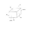
Hereinafter, embodiments of the present invention will be described with reference to the drawings. 1 and 2 show the
本実施形態1で割断される割断前磁石10は、焼結金属材料からなる希土類磁石であり、着磁前の状態にある。この割断前磁石10は、第1主面10aと、これに平行な第2主面10bと、これらを結ぶ第3側面10c、第4側面10d、第5側面10e及び第6側面10fとを有する直方体形状をなす(図1及び図2参照)。第3側面10cと第4側面10dが互いに平行であり、第5側面10eと第6側面10fが互いに平行である。 The
このうち、第1主面10aには、この割断前磁石10が割断される際の起点となる割断用溝11,11,…が複数形成されている(図1及び図2参照)。これらの割断用溝11,11,…は、断面が略U字状をなし、第1主面10aの短手方向に平行で、第3側面10c及び第4側面10dにそれぞれ直交するように、第3側面10cから第4側面10dまで形成されている。これらの割断用溝11,11,…は、等間隔で互いに平行に配置されている。 Among these, a plurality of cleaving
この割断前磁石10を割断用溝11,11,…を起点として割断用溝11,11,…に沿って割断すると、複数(本実施形態1では10個)の分割磁石20,20,…が得られる(図3参照)。この分割磁石20は、上記の第1主面10aに対応する第1分割主面20aと、上記の第2主面10bに対応する第2分割主面20bと、上記の第3側面10cに対応する第3分割側面20cと、上記の第4側面10dに対応する第4分割側面20dと、割断によって新たに形成される2つの概略互いに平行な第1割断面20e及び第2割断面20fとを有する直方体形状をなす。なお、割断前磁石10の一方の端部から得られる分割磁石20については、第1割断面20eの代わりに上記の第5側面10eを有し、割断前磁石10の他方の端部から得られる分割磁石20については、第2割断面20fの代わりに上記の第6側面10fを有する。 When the
これらの分割磁石20,20,…は、モータ(不図示)に用いられる。具体的には、モータを構成するロータ(モータ部材)50に穿設された複数の磁石配置孔50h,50h,…に、それぞれ複数個ずつ挿入される(図4参照)。ロータ50は、軸線AXを有する円筒状をなす。ロータ50には、1つの磁石配置孔50hに対し、割断前磁石10の1本分に相当する複数(本実施形態1では10個)の分割磁石20,20,…がそれぞれ挿入されている。磁石配置孔50hに挿入された複数の分割磁石20,20,…は、割断前の割断前磁石10のときと同じ順序で整列している。隣り合う分割磁石20,20同士は、割断前に繋がっていた第1割断面20eと第2割断面20fとが互いに重なり合った状態で、接着剤SZにより互いに接着されている。このように、ロータ50の磁石配置孔50h,50h,…にそれぞれ複数の分割磁石20,20,…を挿入することで、これを用いたモータにおいて、磁石に生じる渦電流損の低減を図ることができる。 These divided
次に、本実施形態1に係る磁石取扱装置100について説明する(図5〜図12参照)。この磁石取扱装置100は、割断前磁石10をその一端から順次割断して得られる複数の分割磁石20,20,…を取り扱う装置であり、分割磁石20,20,…を整列させる磁石整列機構101を備える。この磁石整列機構101は、磁石割断部110と磁石移送部140とを有する。また、本実施形態1の磁石取扱装置100は、磁石配置部130と接着剤塗布部150と全長測定部160とエア吹付部170とを備える。 Next, the
このうち、磁石割断部110は、割断前磁石10を所定位置に保持した後に、これを割断して分割磁石20を形成するように構成されている。具体的には、磁石割断部110は、図5に示すように、割断前磁石10のうち、割断用溝11を境にした一方の側に位置する分割磁石1個分の端部領域10Rを保持する一方側保持部111と、他方の側に位置する残部10Lを保持する他方側保持部121とを有する。これら一方側保持部111及び他方側保持部121は、後述するように、一方側保持部111の他方側保持部121に対する、割断用溝11の底部11j(図2参照)よりも開口部11iをより大きく拡げる形態の相対移動により、割断用溝11を起点としてこの割断用溝11に沿って割断前磁石10を割断する構成とされている。 Among these, the
一方側保持部111は、上方に位置する第1一方側保持部113と、これよりも下方に位置する第2一方側保持部115とを有する。第1一方側保持部113は、上下方向に移動可能に配設され、割断前磁石10を保持するときに、割断前磁石10の第1主面10aに上方から当接し、これを下方に押圧する。また、第2一方側保持部115は、回動軸115jを有し、この回動軸115jを中心として回動可能に配設されている。回動軸115jは、水平方向で、かつ、この磁石取扱装置100に割断前磁石10をセットしたときに、割断前磁石10の割断用溝11と平行となる方向に延びる形態に配置されている。第2一方側保持部115は、割断前磁石10を保持するときに、割断前磁石10の第2主面10bに下方から当接する。このように、一方側保持部111は、その第1一方側保持部113と第2一方側保持部115との間に割断前磁石10(端部領域10R)を狭持して、これを保持する。 The one-
他方側保持部121は、上方に位置する第1他方側保持部123と、これよりも下方に位置する第2他方側保持部125とを有する。第1他方側保持部123は、上下方向に移動可能に配設され、割断前磁石10を保持するときに、割断前磁石10の第1主面10aに上方から当接し、これを下方に押圧する。また、第2他方側保持部125は、この磁石取扱装置100の所定位置に固設され、割断前磁石10を保持するときに、割断前磁石10の第2主面10bに下方から当接する。このように、他方側保持部121は、その第1他方側保持部123と第2他方側保持部125との間に割断前磁石10(残部10L)を狭持して、これを保持する。 The other
割断前磁石10を割断する際、一方側保持部111の第2一方側保持部115を、回動軸115jを中心として、図5中、時計回りに回動させると、一方側保持部111全体が、割断前磁石10(端部領域10R)を保持した状態を維持しつつ、回動軸115jを中心として、図5中、時計回りに回動する。一方、他方側保持部121は移動しないので、この一方側保持部111の回動(他方側保持部121に対する相対移動)により、割断前磁石10は、端部領域10Rと残部10Lとの間の割断用溝11において、その底部11jよりも開口部11iがより大きく拡げられ、この割断用溝11を起点としてこの割断用溝11に沿って割断される。 When the
次に、磁石配置部130について説明する(図5及び図6参照)。磁石配置部130は、この磁石取扱装置100の所定位置に固設され、割断により得られた複数の分割磁石20,20,…を整列した状態に保持する構成とされている。また、磁石配置部130は、分割磁石20,20,…から生じた磁石の破片を分割磁石20,20,…から分離させる形態とされている。具体的には、磁石配置部130は、筒状をなし、その内側に磁石移動整列部131と破片排出部133とを有する(図6参照)。 Next, the magnet arrangement | positioning
磁石移動整列部131は、分割磁石20,20,…が、その長手方向に移動可能な直方体状の空間を構成している。この磁石移動整列部131には、1個分の割断前磁石10に相当する複数(本実施形態では10個)の分割磁石20,20,…を、割断前と同じ状態に整列させて収容できる。この磁石移動整列部131は、その入口部131pが斜め上方を向き、出口部131qが斜め下方を向くように、水平方向に対して傾斜して(傾斜角α1)配設されている。磁石移動整列部131の出口部131qには、この出口部131qを開閉可能な開閉蓋135が取り付けられている。 The magnet
また、破片排出部133は、断面コ字状を有し、磁石移動整列部131の下方に、これに沿って配置されており、この破片排出部133のなす空間が磁石移動整列部131のなす空間と繋がっている。このため、割断により生じた磁石の破片が、分割磁石20と共に磁石移動整列部131内に押し込まれた場合や、分割磁石20とは別に磁石移動整列部131内に侵入してきた場合、磁石の破片は、磁石移動整列部131から下方に落下して分割磁石20から分離し、破片排出部133に排出される。更に、この磁石の破片は、破片排出部133内を下方に向かって滑り落ちていき、破片排出部133の出口部133qから装置外部へ排出される。 The
次に、磁石移送部140について説明する(図9参照)。磁石移送部140は、分割磁石20を個々に磁石割断部110のうちの一方側保持部111から磁石配置部130の磁石移動整列部131内に押し込んで移動させる。そして、先に割断された分割磁石20に対し、その次に割断された分割磁石20を、割断により生じた一対の割断面(第1割断面20e及び第2割断面20f)同士の対応する凹凸が対向する配置に、互いに重ね合わせて整列させる。 Next, the
具体的には、この磁石移送部140は、棒状の移送子141を有する。この移送子141は、磁石割断部110の一方側保持部111に保持された分割磁石20の第2割断面20fを、磁石配置部130に向けて押し、この分割磁石20を、一方側保持部111から磁石配置部130内に、更にこの磁石配置部内を斜め下方に移動させる。そして、この分割磁石20を、この分割磁石20の前に磁石配置部130内に収容され、先に割断された分割磁石20に当接させて、磁石配置部130内の各分割磁石20,20,…を整列させる。即ち、後から挿入した分割磁石20の第1割断面20eと、これより先に収容し分割磁石20の第2割断面20fの対応する凹凸が対向する配置にして、磁石配置部130内の各分割磁石20,20,…を互いに重ね合わせて整列させる。 Specifically, the
次に、接着剤塗布部150について説明する(図10参照)。接着剤塗布部150は、上述の磁石移送部140を用いて、次に割断された分割磁石20を整列させるのに先立ち、先に磁石配置部130内に収容した分割磁石20の第2割断面20fに接着剤SZを塗布する構成とされている。具体的には、接着剤塗布部150は、棒状のノズル151を有し、その先端に位置する吐出部151sから接着剤SZを吐出することができる。接着剤塗布部150は、そのノズル151を、既に磁石配置部130内に収容されている分割磁石20の第2割断面20fに接近或いは当接させ、その後、吐出部151sから接着剤SZを吐出して、これを分割磁石20の第2割断面20fに塗布する。 Next, the
次に、全長測定部160について説明する(図11参照)。全長測定部160は、整列させた複数の分割磁石20,20,…の全長、例えば、割断前磁石10の1個分に相当する10個の分割磁石20,20,…を整列させた状態における、磁石整列方向の全長LAを測定可能に構成されている。具体的には、全長測定部160は、棒状の測定用挿入子161を有し、これを、磁石配置部130に最後に収容した分割磁石20の第6側面10fに当接させることで、整列させた分割磁石20,20,…全体の全長LAを測定する。 Next, the full
次に、エア吹付部170について説明する(図7参照)。エア吹付部170は、割断前磁石10を割断した後に、割断により生じた一対の第1割断面20e及び第2割断面20fにエアを吹き付ける構成とされている。具体的には、エア吹付部170は、磁石割断部110の上方に配設され、上方から、割断により生じた第1割断面20e及び第2割断面20fのそれぞれに同時にエアを吹き付ける。 Next, the
次に、この磁石取扱装置100による磁石の取り扱いについて更に具体的に説明する。
まず、この磁石取扱装置100に割断前磁石10をセットする。即ち、磁石割断部110のうち、一方側保持部111で、割断用溝11を境にした割断前磁石10の一方の側(図5中、右側)を保持し、他方側保持部121で、割断前磁石10の他方の側(図5中、左側)を保持する。具体的には、割断前磁石10のうち、最も第5側面10e側に位置する割断用溝11を境にして、第5側面10e側に位置する分割磁石20の1個分の端部領域10Rを一方側保持部111で保持し、残りの部分である残部10Lを他方側保持部121で保持する。
なお、図5は、既に2個の分割磁石20,20が割断され、これから3個目の分割磁石20を割断する様子を示している。このため、割断前磁石10のうち、最も第1割断面20e側(図5中、最も右側)に位置する割断用溝11を境にして、これより第1割断面20e側(右側)に位置する端部領域10Rを一方側保持部111で保持し、残部10Lを他方側保持部121で保持している。Next, the handling of the magnet by the
First, the
FIG. 5 shows a state in which the two divided
割断前磁石10を保持する際、一方側保持部111は、その第1一方側保持部113が、上方から割断前磁石10の第1主面10aに当接して、これを下方に押圧すると共に、第2一方側保持部115が、下方から割断前磁石10の第2主面10bに当接する。これにより、第1一方側保持部113と第2一方側保持部115との間に割断前磁石10が狭持される。
また、他方側保持部121は、その第1他方側保持部123が上方から割断前磁石10の第1主面10aに当接し、これを下方に押圧すると共に、第2他方側保持部125が、下方から割断前磁石10の第2主面10bに当接する。これにより、第1他方側保持部123と第2他方側保持部125との間に割断前磁石10が狭持される。When holding the
The other
磁石割断部110により割断前磁石10を保持した後は、図7に示すように、一方側保持部111の他方側保持部121に対する、割断用溝11の底部11j(図2参照)よりも開口部11iをより大きく拡げる形態の相対移動により、割断用溝11を起点としてこの割断用溝11に沿って割断前磁石10を割断する。
具体的には、一方側保持部111の第2一方側保持部115を、回動軸115jを中心として、図7中、時計回りに回動させると、一方側保持部111全体が、割断前磁石10を保持した状態を維持しつつ、回動軸115jを中心として、図7中、時計回りに回動する。一方、他方側保持部121は移動しないので、この一方側保持部111の回動(他方側保持部121に対する相対移動)により、割断前磁石10は、割断用溝11の底部11jよりも開口部11iがより大きく拡げられ、割断用溝11を起点として割断用溝11に沿って割断される。そして、分割磁石20が得られる。After the
Specifically, when the second one-
割断後は、エア吹付部170により、割断により生じた一対の割断面(割断前磁石10の第1割断面10e及び分割磁石20の第2割断面20f)に、それぞれ上方からエアを吹き付けて、割断時に生じた磁石の破片を第1割断面10e及び第2割断面20fから吹き飛ばす。 After the cleaving, air is blown from above to the pair of cleaved surfaces (the first
次に、一方側保持部111全体を、割断により得られた分割磁石20を保持した状態を維持しつつ、回動軸115jを中心として、図8中、時計回りに更に回動させて、一方側保持部111を磁石配置部130の近傍に配置する。この状態で、一方側保持部111における第1一方側保持部113と第2一方側保持部115との間に形成されている磁石保持空間KJの水平方向に対する傾斜角β1が、前述の磁石配置部130の磁石移動整列部131の傾斜角α1と一致すると共に、磁石保持空間KJと磁石移動整列部131とが僅かな間隙をあけて連なる。 Next, while maintaining the state where the divided
次に、磁石移送部140の移送子141により、割断により得られた分割磁石20を、一方側保持部111の磁石保持空間KJから磁石配置部130の磁石移動整列部131内に押し込んで移動させる(図9参照)。そして、磁石移動整列部131内において、互いに隣り合う分割磁石20,20の割断により生じた一対の割断面(第1割断面20e及び第2割断面20f)同士を互いに重ね合わせて、各分割磁石20,20,…を割断前と同じ順序に整列させる(これが前述の磁石整列工程に相当する)。 Next, the
具体的には、一方側保持部111による分割磁石20の保持を解除すると共に、磁石移送部140の移送子141を移動させて、一方側保持部111の磁石保持空間KJに挿入する。そして、この移送子141により、磁石保持空間KJにある分割磁石20の第2割断面20fを、磁石配置部130の磁石移動整列部131に向けて押し、この分割磁石20を磁石保持空間KJから磁石移動整列部131内に、更にこの磁石移動整列部131内を斜め下方に移動させる。 Specifically, the holding of the divided
そして、この分割磁石20をこの分割磁石20の前に磁石配置部130内に収容した分割磁石20に当接させて、磁石配置部130(磁石移動整列部131)内の各分割磁石20,20,…を整列させる。即ち、今回割断した分割磁石20の第1割断面20eと、前回割断した分割磁石20の第2割断面20fの対応する凹凸が対向する配置にして、磁石移動整列部131内の各分割磁石20,20,…を互いに重ね合わせて整列させる。その際、前回割断した分割磁石20の第2割断面20fには、接着剤SZが塗布されているので、今回割断した分割磁石20の第1割断面20eと前回割断した分割磁石20の第2割断面20fとが互いに接着され、隣り合う分割磁石20,20同士が互いに固定される(これが前述の接着工程の一部である)。なお、接着剤SZが第1割断面20eと第2割断面20fとの間で馴染んで両者が密着するように、磁石移送部140の移送子141で今回割断した分割磁石20を押圧すると良い。各分割磁石20,20,…を整列させた後は、磁石移送部140の移送子141を後退させる。 Then, the divided
次に、図10に示すように、接着剤塗布部150により、磁石配置部130の磁石移動整列部131内に収容した、上述の分割磁石20の第2割断面20fに接着剤SZを塗布する。具体的には、接着剤塗布部150のノズル151を、磁石配置部130の磁石移動整列部131内に挿入する。そして、ノズル151の吐出部151sを、上述の分割磁石20の第2割断面20fに接近或いは当接させる。その後、吐出部151sから接着剤SZを吐出して、この分割磁石20の第2割断面20fに塗布する(これが前述の接着工程を一部である)。接着剤SZを塗布した後は、接着剤塗布部150のノズル151を後退させる。このように接着剤SZを塗布しておくことにより、次に収容する分割磁石20とこの分割磁石20とを互いに接着できる。 Next, as illustrated in FIG. 10, the
次に、一方側保持部111を、回動軸115jを中心に、図10中、反時計回りに回動させて、図5に示したように、一方側保持部111を元の位置に戻す。また、他方側保持部121による割断前磁石10の保持を解除して、残った割断前磁石10を、一方側保持部111に向けて、分割磁石20の1個分の長さだけ、図5中、右側へ移動させる。
その後は、前述のように、一方側保持部111及び他方側保持部121により、残った割断前磁石10を再び保持し、更にこれを割断する。その後、割断により新たに得られた分割磁石20を磁石配置部130内に移動させて整列させる(磁石整列工程)。そして、これを、当初の割断前磁石10が合計10個の分割磁石20に割断されるまで繰り返し行う。隣り合う分割磁石20,20同士は、前述のように互いに接着されるので、整列させた複数の分割磁石20,20,…は一体化される。Next, the one
Thereafter, as described above, the one-
当初の割断前磁石10の1個分に当たる、10個の分割磁石20,20,…を磁石配置部130内に収容した後は、図11に示すように、全長測定部160により、整列させた分割磁石20,20,…全体の全長LAを測定する。具体的には、全長測定部160の測定用挿入子161を、磁石配置部130の磁石移動整列部131まで移動させて、磁石配置部130に最後に収容した分割磁石20の第6側面10fに当接させる。これにより、整列させた分割磁石20,20,…全体の全長LAを測定する。全長LAを測定した後は、全長測定部160の測定用挿入子161を後退させる。 After the ten divided
次に、図12に示すように、磁石移送部140により、磁石配置部130の磁石移動整列部131内に収容されている複数の分割磁石20,20,…を、磁石移動整列部131から装置外部に排出する。具体的には、磁石移送部140の移送子141を、磁石配置部130内に挿入し、磁石配置部130に最後に収容した分割磁石20の第6側面10fに当接させる。そして、磁石配置部130の開閉蓋135を開けると共に、移送子141により、分割磁石20の第6側面10fを押して、一体された各分割磁石20,20,…を磁石移動整列部131から装置外部に排出する。
その後は、ロータ50を用意し(図4参照)、一体化された各分割磁石20,20,…を、ロータ50に穿設された各磁石配置孔50h,50h,…にそれぞれ挿入する。更に、このロータ50を用いて、モータを組み付ける。Next, as shown in FIG. 12, a plurality of divided
Thereafter, the
以上で説明したように、本実施形態1の磁石取扱装置100では、磁石整列機構101により、先に割断された分割磁石20に対し、その次に割断された分割磁石20を、割断により生じた一対の割断面20e,20f同士の対応する凹凸が対向する配置に、互いに重ね合わせて整列させる。これにより、一対の割断面20e,20f同士の間に大きな隙間を生じることなく、分割磁石20,20同士を互いに重ね合わせることができ、また、隣り合う分割磁石20,20毎の隙間の大きさに、大きなバラツキが生じることもない。このため、この磁石取扱装置100を用いれば、隣り合う分割磁石20,20の割断面20e,20f同士の隙間を小さくし、整列させた分割磁石20,20,…の全長を小さくできる。また、整列させた分割磁石20,20,…の全長バラツキを小さくできる。 As explained above, in the
更に、本実施形態1では、磁石取扱装置100に磁石配置部130を備え、各分割磁石20,20,…を整列させた状態で適切に保持できる。
また、本実施形態1では、次に割断された分割磁石20を整列させるのに先立ち、接着剤塗布部150で先に収容した分割磁石20の第2割断面20fに接着剤SZを塗布する。このため、隣り合う分割磁石20,20同士を接着により互いに固定することで、複数の分割磁石20,20,…を一体化できる。従って、磁石配置部130内に整列させた分割磁石20,20,…を、磁石配置部130から一体化した状態で取り出すことができ、その後も、整列させた分割磁石20,20,…を一体化した状態で取り扱うことができるので、各分割磁石20,20,…の取り扱いが容易である。Furthermore, in the first embodiment, the
In the first embodiment, the adhesive SZ is applied to the second
また、本実施形態1では、全長測定部160が、磁石配置部130内に収容した複数の分割磁石20,20,…全体の全長LAを測定できるので、整列させた分割磁石20,20,…をこの磁石分割装置100から取り出す前に、この磁石取扱装置100において、事前に、整列させた分割磁石20,20,…の全長LAの適否を検査できる。
また、本実施形態1では、磁石整列機構101に、割断前磁石10を割断する磁石割断部110を有する。このため、1つの装置内で、割断前磁石10の割断から、割断して得た分割磁石20,20,…の整列まで、一連の操作を行えるので、装置を簡易なものとすることができる。Moreover, in this Embodiment 1, since the full
In the first embodiment, the
また、本実施形態1では、エア吹付部170が、割断前磁石10を割断した直後に、割断により生じた一対の第1割断面20e及び第2割断面20fにエアを吹き付けるので、割断時に磁石の破片が生じても、これを割断面20e,20fから吹き飛ばすことができる。このため、分割磁石20を磁石配置部130に収容する際に、分割磁石20と共に磁石の破片が磁石配置部130内に収容されるのを防止できる。従って、磁石の破片が隣り合う分割磁石20,20の割断面20e,20f同士の間に入って隙間が大きくなったり、整列させた分割磁石20,20,…の全長バラツキが大きくなることを防止できる。 Moreover, in this Embodiment 1, since the
また、本実施形態1では、磁石配置部130に前述の破片排出部133が設けられている。このため、割断時に生じた磁石の破片が、磁石配置部130(磁石移動整列部131)内にまで移動してきても、この磁石の破片は、分割磁石20から分離し、磁石移動整列部131から落下して、破片排出部133に排出される。従って、磁石の破片が隣り合う分割磁石20,20の割断面20e,20f同士の間に入って隙間が大きくなったり、整列させた分割磁石20,20,…の全長バラツキが大きくなることを防止できる。 In the first embodiment, the
(実施形態2)
次いで、第2の実施の形態について説明する。本実施形態2の磁石取扱装置200では、接着剤塗布部150の代わりに、テープ貼付機構250を有する点が、上記実施形態1の磁石取扱装置100と異なる。それ以外は、基本的に上記実施形態1と同様であるので、上記実施形態1と同様な部分の説明は、省略または簡略化する。図13〜図15に、本実施形態2に係る磁石取扱装置200を示す。図13は、磁石取扱装置200の全体を示す。また、図14は、図13のB−B断面を示し、図15は、図13のC方向から見た様子を示す。(Embodiment 2)
Next, a second embodiment will be described. The
本実施形態2の磁石取扱装置200は、磁石割断部110及び磁石移送部140を有する磁石整列機構101と、磁石配置部230と、テープ貼付機構250と、全長測定部160と、エア吹付部170とを備える。このうち、磁石割断部110、磁石移送部140、全長測定部160及びエア吹付部170については、上記実施形態1の磁石取扱装置100と同様である。 The
一方、磁石配置部230は、上記実施形態1の磁石配置部130と異なる。即ち、この磁石配置部230は、上記実施形態1と同様な磁石移動整列部131及び破片排出部133を有する他に、テープ貼付用溝部237を有する。このテープ貼付用溝部237は、磁石移動整列部131の側方に、磁石移動整列部131に通じるようにして、磁石移動整列部131に沿って形成されている。このテープ貼付用溝部237により、磁石配置部230(磁石移動整列部131)内に収容した各分割磁石20,20,…の第3分割側面20c,20c,…の大部分がそれぞれ外部に露出する。 On the other hand, the
テープ貼付機構250は、磁石移動整列部131の側方(テープ貼付用溝部237の側方)に、自身が移動可能に配置されている(図15参照)。このテープ貼付機構250は、整列させた複数の分割磁石20,20,…に、片面に接着層SSが設けられた接着テープSTを架け渡して貼付するように構成されている。具体的には、テープ貼付機構250は、テープ貼付用ローラ251とテープ送出部253とを有する。テープ送出部253は、接着テープSTを順次送り出すことができる。 The
また、テープ貼付用ローラ251は、その一部が磁石配置部230のテープ貼付用溝部237内に配置され、磁石移動整列部131内に収容した分割磁石20,20,…の第3分割側面20c,20c,…に接触する。そして、自身が回転しながら、分割磁石20,20,…の第3分割側面20c,20c,…に沿って斜め上方に移動することにより、テープ送出部253から送り出された接着テープSTを、各分割磁石20,20,…に架け渡しながら貼付することができる。 Further, a part of the
本実施形態2の磁石取扱装置200では、当初の割断前磁石10の1個分に当たる10個の分割磁石20,20,…を磁石配置部230内に収容し、図15に示すように、上述のテープ貼付機構250により、各分割磁石20,20,…に接着テープSTを架け渡して貼付し、隣り合う分割磁石20,20同士を互いに固定する(これが前述の固定工程に相当する)。 In the
即ち、テープ貼付用ローラ251の一部を、磁石配置部230のテープ貼付用溝部237内に配置し、磁石移動整列部131内に収容した分割磁石20,20,…の第3分割側面20c,20c,…に接触させる。一方で、テープ送出部253から接着テープSTを送り出す。そして、テープ貼付用ローラ251を回転させながら、分割磁石20,20,…の第3分割側面20c,20c,…に沿って斜め上方に移動させることにより、接着テープSTを分割磁石20,20,…の各第3分割側面20c,20c,…に架け渡しながら貼付する。これにより、複数の分割磁石20,20,…が互いに固定されて一体化される。 That is, a part of the
その後は、上記実施形態1と同様に、磁石移送部140により、磁石配置部130の磁石移動整列部131内に収容されている複数の分割磁石20,20,…を、磁石移動整列部131から装置外部に取り出す(図12参照)。そして、一体化された各分割磁石20,20,…を、ロータ50に穿設された各磁石配置孔50h,50h,…にそれぞれ挿入する。更に、このロータ50を用いて、モータを組み付ける。 Thereafter, similarly to the first embodiment, the
このように、本実施形態2の磁石取扱装置200では、テープ貼付機構250が、複数の分割磁石20,20,…を整列させた状態で、これらの分割磁石20,20,…に接着テープSTを架け渡して貼付して、これらを互いに固定する。これにより、各分割磁石20,20,…を一体化できるので、その後の分割磁石20,20,…の取り扱いが容易である。その他、上記実施形態1と同様な部分は、上記実施形態1と同様な作用効果を奏する。 As described above, in the
(実施形態3)
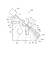
次いで、第3の実施の形態について説明する。上記実施形態1,2の磁石取扱装置100,200では、割断により得られた分割磁石20を、磁石配置部130,230に収容して整列させると共に一体化させる。そしてその後、整列させた分割磁石20,20,…を磁石取扱装置100,200から取り出して、別途用意したロータ50の磁石配置孔50hに挿入している。これに対し、本実施形態3の磁石取扱装置300では、割断により得られた分割磁石20を、磁石配置部に収容することなく、直接、ロータ50の磁石配置孔50hに挿入して整列させる。それ以外は、基本的に上記実施形態1等と同様であるので、上記実施形態1等と同様な部分の説明は、省略または簡略化する。図16〜図21に、本実施形態3に係る磁石取扱装置300を示す。(Embodiment 3)
Next, a third embodiment will be described. In the
本実施形態3の磁石取扱装置300は、割断前磁石10を割断して得られる複数の分割磁石20,20,…を、ロータ50(図4参照)に形成された磁石配置孔50h,50h,…に挿入する装置であり、磁石割断部110及び磁石移送部140を有する磁石整列機構101と、接着剤塗布部150と、全長測定部160と、エア吹付部170と、モータ部材保持部380とを備える。このうち、磁石割断部110とエア吹付部170は、その形態も動作も上記実施形態1の磁石取扱装置100と同様である。 In the
一方、磁石移送部140は、上記実施形態1と同様な形態をなすが、この磁石取扱装置300においては、磁石移送部140は、分割磁石20を個々に磁石割断部110の一方側保持部111から、モータ部材保持部380に保持されたロータ50の磁石配置孔50hに挿入する(図19参照)。そして、互いに隣り合う分割磁石20,20の割断により生じた一対の割断面(第1割断面20e及び第2割断面20f)同士を互いに重ね合わせて、各分割磁石20,20,…を割断前と同じ順序に整列させる。 On the other hand, the
具体的には、磁石移送部140の移送子141で、磁石割断部110の一方側保持部111に保持された分割磁石20を、ロータ50の磁石配置孔50hに挿入する。そして、この分割磁石20をこの分割磁石20の前に磁石配置孔50hに挿入した分割磁石20に当接させて、磁石配置孔50h内で各分割磁石20,20,…を整列させる。即ち、今回割断した分割磁石20の第1割断面20eと、前回割断した分割磁石20の第2割断面20fの対応する凹凸が対向する配置にして、磁石配置孔50h内の各分割磁石20,20,…を互いに重ね合わせて整列させる。 Specifically, the
また、接着剤塗布部150は、上記実施形態1と同様な形態をなすが、この磁石取扱装置300においては、接着剤塗布部150のノズル151を、ロータ50の磁石配置孔50hに挿入する(図20参照)。そして、既に磁石配置孔50h内に挿入されている分割磁石20の第2割断面20fに接近或いは当接した後、ノズル151の吐出部151sから接着剤SZを吐出して、この分割磁石20の第2割断面20fに塗布する。 The
また、全長測定部160は、上記実施形態1と同様な形態をなすが、この磁石取扱装置300においては、ロータ50の磁石配置孔50hに挿入された、当初の割断前磁石10の1個分に相当する10個の分割磁石20,20,…の磁石整列方向の全長LAを測定する(図21参照)。具体的には、全長測定部160の測定用挿入子161を、磁石配置孔50hに最後に挿入した分割磁石20の第6側面10fに当接させることで、整列させた複数の分割磁石20,20,…全体の全長LAを測定する。 Further, the full
モータ部材保持部380は、ロータ50を所定の姿勢に保持する構成とされている(図16参照)。このモータ部材保持部380は、ロータ50が載置される回転テーブル381と、この回転テーブルを回転可能な回転軸383とを有する。ロータ50を載置した状態で、ロータ50の軸線AXと回転テーブル381の軸線BXとが一致するので、回転テーブル381と回転させると、ロータ50は軸線AXを中心として回転する。また、回転テーブル381は、水平方向に対して傾斜して配置されており、これにロータ50を載置すると、ロータ50の磁石配置孔50h,50h,…が、水平方向に対して傾斜した状態(傾斜角α2)で配置される。 The motor
次に、この磁石取扱装置300による磁石の取り扱いについて更に具体的に説明する。
まず、図16に示すように、この磁石取扱装置300に割断前磁石10をセットする。即ち、上記実施形態1と同様に、磁石割断部110のうち、一方側保持部111で、割断用溝11を境にした割断前磁石10の一方の側(図16中、右側)を保持し、他方側保持部121で、割断前磁石10の他方の側(図16中、左側)を保持する。なお、図16は、既に2個の分割磁石20,20が割断され、これから3個目の分割磁石20を割断する様子を示している。
また、この磁石取扱装置300のモータ部材保持部380の回転テーブル381にロータ50をセットしておく。Next, the handling of the magnet by the
First, as shown in FIG. 16, the
Further, the
磁石割断部110により割断前磁石10を保持した後は、図17に示すように、上記実施形態1と同様に、一方側保持部111の他方側保持部121に対する、割断用溝11の底部11jよりも開口部11iをより大きく拡げる形態の相対移動により、割断用溝11を起点として割断用溝11に沿って割断前磁石10を割断する。
また、割断後は、上記実施形態1と同様に、エア吹付部170により、割断により生じた第1割断面20e及び第2割断面20fに、それぞれ上方からエアを吹き付けて、割断時に生じた磁石の破片を第1割断面20e及び第2割断面20fから吹き飛ばす。After holding the
In addition, after the cleaving, similarly to the first embodiment, the
次に、一方側保持部111全体を、割断により得られた分割磁石20を保持した状態を維持しつつ、回動軸115jを中心として、図18中、時計回りに更に回動させて、一方側保持部111を、モータ部材保持部380に保持されたロータ50の磁石配置孔50hの近傍に配置する。具体的には、磁石保持空間KJと磁石配置孔50hとが僅かな間隙をあけて連なる状態とする。 Next, while maintaining the state where the divided
次に、磁石移送部140により、割断により得られた分割磁石20を、一方側保持部111の磁石保持空間KJからロータ50の磁石配置孔50hに挿入する(図19参照)。そして、磁石配置孔50h内において、互いに隣り合う分割磁石20,20の割断により生じた一対の割断面(第1割断面20e及び第2割断面20f)同士を、対応する凹凸が対向する配置にして、各分割磁石20,20,…を互いに重ね合わせて割断前と同じ順序に整列させる(磁石整列工程)。 Next, the divided
具体的には、一方側保持部111による分割磁石20の保持を解除すると共に、磁石移送部140の移送子141を移動させて、磁石保持空間KJにある分割磁石20の第2割断面20fを押して、分割磁石20を磁石配置孔50h内に挿入する。そして、この分割磁石20を、その前に磁石配置孔50hに挿入した分割磁石20に当接させて、磁石配置孔50h内で各分割磁石20,20,…を整列させる。即ち、今回割断した分割磁石20の第1割断面20eと、前回割断した分割磁石20の第2割断面20fの対向する凹凸が対向する配置にして、磁石配置孔50h内の各分割磁石20,20,…を互いに重ね合わせて整列させる。その際、先に収容した分割磁石20の第2割断面20fには、接着剤SZが塗布されているので、今回収容した分割磁石20の第1割断面20eと先に収容した分割磁石20の第2割断面20fとが互いに接着され、隣り合う分割磁石20,20同士が互いに固定される(接着工程)。各分割磁石20,20,…を整列させた後は、磁石移送部140の移送子141を後退させる。 Specifically, the holding of the divided
次に、図20に示すように、実施形態1と同様に、接着剤塗布部150により、磁石配置孔50hに挿入した上述の分割磁石20の第2割断面20fに接着剤SZを塗布する。接着剤SZを塗布した後は、接着剤塗布部150のノズル151を後退させる。 Next, as shown in FIG. 20, as in the first embodiment, the
次に、一方側保持部111を、回動軸115jを中心に、図20中、反時計回りに回動させて、図16に示したように、一方側保持部111を元の位置に戻す。また、他方側保持部121による割断前磁石10の保持を解除して、残った割断前磁石10を、一方側保持部111に向けて、分割磁石20の1個分の長さだけ、図20中、右側へ移動させる。
その後は、前述のように、一方側保持部111及び他方側保持部121により、残った割断前磁石10を再び保持し、更にこれを割断する。その後、割断により新たに得られた分割磁石20をロータ50の磁石配置孔50hに挿入して整列させる(磁石整列工程)。そして、これを、10個の分割磁石20が磁石配置孔50hに挿入されるまで繰り返し行う。Next, the one
Thereafter, as described above, the one-
当初の割断前磁石10の1個分に当たる10個の分割磁石20,20,…をロータ50の磁石配置孔50hに挿入した後は、図21に示すように、全長測定部160により、整列させた複数の分割磁石20,20,…全体の全長LAを測定する。具体的には、全長測定部160の測定用挿入子161を、磁石配置孔50hに最後に挿入した分割磁石20の第6側面10fに当接させて、整列させた複数の分割磁石20,20,…全体の全長LAを測定する。全長LAを測定した後は、全長測定部160の測定用挿入子161を後退させる。 After the ten divided
次に、モータ部材保持部380の回転テーブル381を、回転軸383により回転させて、次に分割磁石20,20,…を挿入する予定の磁石配置孔50hを所定位置に配置する。その後は、前述した各工程を繰り返し行って、この磁石配置孔50hにも複数(10個)の分割磁石20,20,…を挿入する。更に、以上の操作を繰り返し行い、ロータ50の全ての磁石配置孔50hに、複数(10個)の分割磁石20,20,…を挿入する。その後は、このロータ50をモータ部材保持部380から取り外し、これを用いてモータを組み付ける。 Next, the rotary table 381 of the motor
以上で説明したように、本実施形態3の磁石取扱装置300も、磁石整列機構101により、先に割断された分割磁石20に対し、その次に割断された分割磁石20を、割断により生じた一対の割断面20e,20f同士の対応する凹凸が対向する配置に、互いに重ね合わせて整列させる。これにより、一対の割断面20e,20f同士の間に大きな隙間を生じることなく、分割磁石20,20同士を互いに重ね合わせることができ、また、隣り合う分割磁石20,20毎の隙間の大きさに、大きなバラツキが生じることもない。このため、この磁石取扱装置300を用いれば、隣り合う分割磁石20,20の割断面20e,20f同士の隙間を小さくし、整列させた分割磁石20,20,…の全長を小さくできる。また、整列させた分割磁石20,20,…の全長バラツキを小さくできる。 As described above, the
更に、本実施形態3では、磁石取扱装置300を用いて、各分割磁石20,20,…を、直接、ロータ50の磁石配置孔50h内に整列させたので、一旦、整列させた分割磁石20,20,…を、ロータ50の磁石配置孔50h,50h,…に挿入するよりも簡易である。 Further, in the third embodiment, since each of the divided
また、本実施形態3でも、接着剤塗布部150により、次に割断した分割磁石20を整列させるのに先立ち、先に収容した分割磁石20の第2割断面20fに接着剤SZを塗布する。このように、隣り合う分割磁石20,20同士を接着により互いに固定することで、複数の分割磁石20,20,…を一体化できる。従って、各分割磁石20,20,…が磁石配置孔50h内で位置ズレするのを防止できる。
また、本実施形態3では、全長測定部160が、磁石配置孔50hに挿入した複数の分割磁石20,20,…全体の全長LAを測定できるので、この磁石取扱装置300において、整列させた分割磁石20,20,…の全長LAの適否を検査できる。Also in the third embodiment, the
In the third embodiment, the total
また、本実施形態3では、エア吹付部170が、割断前磁石10を割断した直後に、割断により生じた一対の割断面20e,20fにエアを吹き付けるので、割断時に磁石の破片が生じても、これを割断面20e,20fから吹き飛ばすことができる。このため、割断された分割磁石20をロータ50の磁石配置孔50hに挿入する際に、分割磁石20と共に磁石の破片が磁石配置孔50hに挿入されるのを防止できる。従って、磁石の破片が隣り合う分割磁石20,20の割断面20e,20f同士の間に入って隙間が大きくなったり、整列させた分割磁石20,20,…の全長バラツキが大きくなることを防止できる。その他、上記実施形態1または2と同様な部分は、上記実施形態1または2と同様な作用効果を奏する。 Moreover, in this Embodiment 3, since the
以上において、本発明を実施形態1〜3に即して説明したが、本発明は上述の実施形態1〜3に限定されるものではなく、その要旨を逸脱しない範囲で、適宜変更して適用できることは言うまでもない。
例えば、上記実施形態1,3では、接着剤SZを、先に割断した分割磁石20の第2割断面20fに塗布したが、その次に割断した分割磁石20の第1割断面20eに塗布するようにしてもよい。或いは、接着剤SZを、先に割断した分割磁石20の第2割断面20fと、その次に割断した分割磁石20の第1割断面20eの両方に塗布するようにしてもよい。In the above, the present invention has been described with reference to the first to third embodiments. However, the present invention is not limited to the above first to third embodiments, and may be appropriately modified and applied without departing from the gist thereof. Needless to say, you can.
For example, in the first and third embodiments, the adhesive SZ is applied to the
Claims (10)
先に割断された前記分割磁石に対し、その次に割断された前記分割磁石を、割断により生じた一対の割断面同士の対応する凹凸が対向する配置に、互いに重ね合わせて整列させる構成とされてなる磁石整列機構を備え、
前記磁石整列機構は、
前記割断前磁石を割断する構成とされてなる磁石割断部と、
この磁石割断部で割断された、前記その次に割断された分割磁石を押して移動させて、前記先に割断された分割磁石に当接させる移送子を含む磁石移送部と、を有する
磁石取扱装置。 A magnet handling device that handles a plurality of divided magnets obtained by sequentially cleaving the pre-breaking magnet from one end thereof,
The divided magnets that have been cleaved next to the divided magnets that have been cleaved first are arranged so as to overlap each other in an arrangement in which the corresponding irregularities of a pair of cleaved surfaces that are generated by cleaving face each other. With a magnet alignment mechanism
The magnet alignment mechanism includes:
A magnet cleaving portion configured to cleave the magnet before cleaving;
A magnet handling device comprising: a magnet transfer unit including a transfer element that presses and moves the divided magnets that are cleaved by the magnet cleaving unit to contact the divided magnets that are cleaved first; .
複数の前記分割磁石を整列させた状態で、これらの分割磁石全体の、磁石整列方向の全長を測定する構成とされてなる全長測定部を備える
磁石取扱装置。 The magnet handling device according to claim 1,
A magnet handling apparatus comprising a full length measuring unit configured to measure the total length of all the divided magnets in the magnet alignment direction in a state where a plurality of the divided magnets are aligned.
複数の前記分割磁石を整列した状態に保持する構成とされてなる磁石配置部を備え、
前記磁石整列機構は、
前記磁石配置部内に、前記分割磁石を順に整列させる構成とされてなる
磁石取扱装置。 The magnet handling device according to claim 1 or 2,
Comprising a magnet arrangement portion configured to hold a plurality of the divided magnets in an aligned state;
The magnet alignment mechanism includes:
A magnet handling apparatus configured to sequentially arrange the divided magnets in the magnet arrangement portion.
複数の前記分割磁石を整列した状態に保持する磁石配置孔を有するモータ部材を、所定の姿勢に保持する構成とされてなるモータ部材保持部を備え、
前記磁石整列機構は、
前記モータ部材保持部に保持された前記モータ部材の前記磁石配置孔内に、前記分割磁石を順に整列させる構成とされてなる
磁石取扱装置。 The magnet handling device according to claim 1 or 2,
A motor member holding portion configured to hold a motor member having a magnet arrangement hole for holding the plurality of divided magnets in an aligned state in a predetermined posture;
The magnet alignment mechanism includes:
A magnet handling apparatus configured to sequentially arrange the divided magnets in the magnet arrangement hole of the motor member held by the motor member holding portion.
先に割断された前記分割磁石に対し、その次に割断された前記分割磁石を、割断により生じた一対の割断面同士の対応する凹凸が対向する配置に、互いに重ね合わせて整列させる構成とされてなる磁石整列機構を備え、
複数の前記分割磁石を整列した状態に保持する磁石配置孔を有するモータ部材を、所定の姿勢に保持する構成とされてなるモータ部材保持部を備え、
前記磁石整列機構は、
前記モータ部材保持部に保持された前記モータ部材の前記磁石配置孔内に、前記分割磁石を順に整列させる構成とされてなる
磁石取扱装置。 A magnet handling device that handles a plurality of divided magnets obtained by sequentially cleaving the pre-breaking magnet from one end thereof,
The divided magnets that have been cleaved next to the divided magnets that have been cleaved first are arranged so as to overlap each other in an arrangement in which the corresponding irregularities of a pair of cleaved surfaces that are generated by cleaving face each other. With a magnet alignment mechanism
A motor member holding portion configured to hold a motor member having a magnet arrangement hole for holding the plurality of divided magnets in an aligned state in a predetermined posture;
The magnet alignment mechanism includes:
A magnet handling apparatus configured to sequentially arrange the divided magnets in the magnet arrangement hole of the motor member held by the motor member holding portion.
先に割断された前記分割磁石に対し、その次に割断された前記分割磁石を、割断により生じた一対の割断面同士の対応する凹凸が対向する配置に、互いに重ね合わせて整列させる構成とされてなる磁石整列機構を備え、
複数の前記分割磁石を整列させた状態で、これらの分割磁石全体の、磁石整列方向の全長を測定する構成とされてなる全長測定部を備える
磁石取扱装置。 A magnet handling device that handles a plurality of divided magnets obtained by sequentially cleaving the pre-breaking magnet from one end thereof,
The divided magnets that have been cleaved next to the divided magnets that have been cleaved first are arranged so as to overlap each other in an arrangement in which the corresponding irregularities of a pair of cleaved surfaces that are generated by cleaving face each other. With a magnet alignment mechanism
A magnet handling apparatus comprising a full length measuring unit configured to measure the total length of all the divided magnets in the magnet alignment direction in a state where a plurality of the divided magnets are aligned.
前記磁石整列機構は、
前記割断前磁石を割断する構成とされてなる磁石割断部を有する
磁石取扱装置。 The magnet handling device according to claim 5 or 6,
The magnet alignment mechanism includes:
A magnet handling device having a magnet cleaving portion configured to cleave the magnet before cleaving.
前記その次に割断された分割磁石の整列に先立ち、前記一対の割断面の少なくとも一方に接着剤を塗布する構成とされてなる接着剤塗布部を備える
磁石取扱装置。 It is a magnet handling device according to any one of claims 1 to 7,
A magnet handling apparatus comprising an adhesive application unit configured to apply an adhesive to at least one of the pair of split sections prior to the alignment of the next divided magnet.
複数の前記分割磁石を整列させた状態で、これらの分割磁石に、片面に接着層を設けた接着テープを架け渡して貼り付ける構成とされてなるテープ貼付機構を備える
磁石取扱装置。 The magnet handling device according to any one of claims 1 to 3 and claim 6,
A magnet handling apparatus provided with a tape sticking mechanism in which a plurality of the split magnets are aligned and an adhesive tape provided with an adhesive layer on one side is stretched over and attached to these split magnets.
前記その次に割断された分割磁石の整列に先立ち、前記一対の割断面のそれぞれにエアを吹き付ける構成とされてなるエア吹付部を備える
磁石取扱装置。 The magnet handling device according to any one of claims 1 to 9,
A magnet handling apparatus comprising an air blowing portion configured to blow air onto each of the pair of split sections prior to the alignment of the next divided magnets.
Applications Claiming Priority (1)
| Application Number | Priority Date | Filing Date | Title |
|---|---|---|---|
| PCT/JP2009/063460 WO2011013209A1 (en) | 2009-07-29 | 2009-07-29 | Apparatus for handling magnet and method for handling magnet |
Publications (2)
| Publication Number | Publication Date |
|---|---|
| JPWO2011013209A1 JPWO2011013209A1 (en) | 2013-01-07 |
| JP5267671B2 true JP5267671B2 (en) | 2013-08-21 |
Family
ID=43528886
Family Applications (1)
| Application Number | Title | Priority Date | Filing Date |
|---|---|---|---|
| JP2011524569A Expired - Fee Related JP5267671B2 (en) | 2009-07-29 | 2009-07-29 | Magnet handling equipment |
Country Status (5)
| Country | Link |
|---|---|
| US (1) | US8672013B2 (en) |
| EP (1) | EP2461461A4 (en) |
| JP (1) | JP5267671B2 (en) |
| CN (1) | CN102474140B (en) |
| WO (1) | WO2011013209A1 (en) |
Cited By (1)
| Publication number | Priority date | Publication date | Assignee | Title |
|---|---|---|---|---|
| JP2016096698A (en) * | 2014-11-17 | 2016-05-26 | トヨタ自動車株式会社 | Rotor manufacturing method |
Families Citing this family (10)
| Publication number | Priority date | Publication date | Assignee | Title |
|---|---|---|---|---|
| US9331557B2 (en) | 2011-03-31 | 2016-05-03 | Toyota Jidosha Kabushiki Kaisha | Cleavage method, rotor manufacturing method, and cleavage apparatus |
| AU2012288174B2 (en) * | 2011-07-27 | 2015-05-21 | Nissan Motor Co., Ltd. | Device for producing field-pole magnet and method for producing same |
| FR2980317B1 (en) * | 2011-09-16 | 2015-02-06 | Alstom Hydro France | METHOD FOR ASSEMBLING AN ELECTRIC MACHINE WITH PERMANENT MAGNETS |
| JP5867102B2 (en) * | 2012-01-16 | 2016-02-24 | 日産自動車株式会社 | Field pole magnet body manufacturing apparatus and method |
| CN104428982B (en) * | 2012-07-13 | 2019-04-26 | 日产自动车株式会社 | The manufacturing device of field pole magnet |
| WO2014030547A1 (en) * | 2012-08-21 | 2014-02-27 | 日産自動車株式会社 | Rotor structure and rotor manufacturing method for permanent magnet type rotating electrical machine |
| US9779871B2 (en) * | 2012-09-21 | 2017-10-03 | Nissan Motor Co., Ltd. | Manufacturing device for cleft magnet |
| DE102015103418B4 (en) | 2015-03-09 | 2019-03-21 | Schuler Pressen Gmbh | Method and device for separating a starting sheet and sheet metal part |
| US11004586B2 (en) * | 2017-09-15 | 2021-05-11 | Siemens Gamesa Renewable Energy A/S | Permanent magnet for a permanent magnet machine |
| DE102018109706A1 (en) * | 2018-04-23 | 2019-10-24 | Emil Schmid Maschinenbau GmbH & Co. KG | Method for equipping an annular rotor unit for an electric motor with magnetic elements |
Citations (5)
| Publication number | Priority date | Publication date | Assignee | Title |
|---|---|---|---|---|
| JPS6179505U (en) * | 1984-10-30 | 1986-05-27 | ||
| JP2007142002A (en) * | 2005-11-16 | 2007-06-07 | Denso Corp | Semiconductor wafer pressing tool and usage thereof |
| JP2007162888A (en) * | 2005-12-15 | 2007-06-28 | Tlv Co Ltd | Temperature responsive valve |
| JP2009142081A (en) * | 2007-12-06 | 2009-06-25 | Toyota Motor Corp | Permanent magnet and method of manufacturing the same, and rotor and ipm motor |
| JP2010252514A (en) * | 2009-04-15 | 2010-11-04 | Nissan Motor Co Ltd | Apparatus for manufacturing magnet body for field pole, manufacturing method thereof and permanent magnet type motor |
Family Cites Families (10)
| Publication number | Priority date | Publication date | Assignee | Title |
|---|---|---|---|---|
| JPS6179505A (en) | 1984-09-28 | 1986-04-23 | イドロマ・エス・ピ−・エ− | Turret for holding tool |
| JP3690067B2 (en) | 1997-06-11 | 2005-08-31 | 株式会社日立製作所 | Permanent magnet rotating electric machine |
| JP2002018797A (en) | 2000-06-29 | 2002-01-22 | Nisshinbo Ind Inc | Dividing method for fragile material board and device therefor |
| JP2002272033A (en) * | 2001-03-13 | 2002-09-20 | Nissan Motor Co Ltd | Rotor of permanent magnet synchronous motor and manufacturing method |
| JP4990599B2 (en) * | 2005-11-15 | 2012-08-01 | 信越化学工業株式会社 | Permanent magnet rotating electric machine |
| EP1786085B1 (en) * | 2005-11-15 | 2016-08-03 | Shin-Etsu Chemical Co., Ltd. | Permanent magnet rotating electric machine |
| JP2007266200A (en) * | 2006-03-28 | 2007-10-11 | Tdk Corp | Magnet composite structure |
| JP2008113530A (en) | 2006-10-31 | 2008-05-15 | Mitsui High Tec Inc | Method and apparatus for inserting magnet material |
| JP4962870B2 (en) * | 2007-06-29 | 2012-06-27 | 日産自動車株式会社 | Method for manufacturing field pole magnet body, method for manufacturing permanent magnet type rotary electric motor, and field pole magnet body |
| US9331557B2 (en) | 2011-03-31 | 2016-05-03 | Toyota Jidosha Kabushiki Kaisha | Cleavage method, rotor manufacturing method, and cleavage apparatus |
-
2009
- 2009-07-29 US US13/387,657 patent/US8672013B2/en not_active Expired - Fee Related
- 2009-07-29 WO PCT/JP2009/063460 patent/WO2011013209A1/en active Application Filing
- 2009-07-29 EP EP09847801.9A patent/EP2461461A4/en not_active Withdrawn
- 2009-07-29 JP JP2011524569A patent/JP5267671B2/en not_active Expired - Fee Related
- 2009-07-29 CN CN200980160680.0A patent/CN102474140B/en not_active Expired - Fee Related
Patent Citations (5)
| Publication number | Priority date | Publication date | Assignee | Title |
|---|---|---|---|---|
| JPS6179505U (en) * | 1984-10-30 | 1986-05-27 | ||
| JP2007142002A (en) * | 2005-11-16 | 2007-06-07 | Denso Corp | Semiconductor wafer pressing tool and usage thereof |
| JP2007162888A (en) * | 2005-12-15 | 2007-06-28 | Tlv Co Ltd | Temperature responsive valve |
| JP2009142081A (en) * | 2007-12-06 | 2009-06-25 | Toyota Motor Corp | Permanent magnet and method of manufacturing the same, and rotor and ipm motor |
| JP2010252514A (en) * | 2009-04-15 | 2010-11-04 | Nissan Motor Co Ltd | Apparatus for manufacturing magnet body for field pole, manufacturing method thereof and permanent magnet type motor |
Cited By (1)
| Publication number | Priority date | Publication date | Assignee | Title |
|---|---|---|---|---|
| JP2016096698A (en) * | 2014-11-17 | 2016-05-26 | トヨタ自動車株式会社 | Rotor manufacturing method |
Also Published As
| Publication number | Publication date |
|---|---|
| US8672013B2 (en) | 2014-03-18 |
| WO2011013209A1 (en) | 2011-02-03 |
| EP2461461A4 (en) | 2017-05-17 |
| JPWO2011013209A1 (en) | 2013-01-07 |
| CN102474140B (en) | 2014-10-15 |
| CN102474140A (en) | 2012-05-23 |
| EP2461461A1 (en) | 2012-06-06 |
| US20120125969A1 (en) | 2012-05-24 |
Similar Documents
| Publication | Publication Date | Title |
|---|---|---|
| JP5267671B2 (en) | Magnet handling equipment | |
| JP5196019B2 (en) | Magnet cleaving device and magnet cleaving method | |
| JP5929153B2 (en) | Field pole magnet body manufacturing apparatus and method | |
| CN103347829B (en) | The method for cutting the glass tape of coating, splices the method for glass tape and the splicing glass tape of correlation | |
| WO2013047298A1 (en) | Manufacturing device for magnet body for field pole and manufacturing method for same | |
| WO2013146528A1 (en) | Filter mounting device | |
| JP2009259747A (en) | Method of manufacturing winding device | |
| WO2013084644A1 (en) | Manufacturing device for magnet for field pole and method for manufacturing same | |
| ITBO20070115A1 (en) | SONOTRODO FOR ULTRASOUND AND CUTTING WELDING UNIT | |
| WO2015004364A1 (en) | Device for inspecting the surface of an electrically conductive part | |
| US9514877B2 (en) | Amorphous core transformer | |
| JP5935895B2 (en) | Cracking magnet manufacturing equipment | |
| JP2019518455A (en) | Apparatus and method for manufacturing tobacco industry products | |
| CN107614175B (en) | A kind of pipe cutting equipment and cutting method | |
| FR2645794A1 (en) | APPARATUS FOR FREE OR LOW PRESSURE EXPANSION FOAM MOLDING AND MANUFACTURING METHOD THEREOF | |
| CN109051942B (en) | Anti-overflow anti-sticking connector for reel printed matter and splicing method | |
| JP2016521978A (en) | Equipment for producing smoker goods | |
| JP6257239B2 (en) | Joint width adjustment jig | |
| JP5751653B2 (en) | Filter mounting device | |
| KR101964122B1 (en) | The nick breaking device | |
| ITBO20000210A1 (en) | METHOD AND DEVICE FOR THE APPLICATION OF CABLE TIES TO CIGARETTE PACKAGES. | |
| CA2622104A1 (en) | Multi-length flexible image bundle | |
| JP2005139005A (en) | Joining paper tube, and method and device for manufacturing the paper tube | |
| WO2013108772A1 (en) | Apparatus for manufacturing magnetic field pole magnet and method of manufacturing same | |
| JP2007302456A (en) | Cylindrical label connecting device |
Legal Events
| Date | Code | Title | Description |
|---|---|---|---|
| TRDD | Decision of grant or rejection written | ||
| A01 | Written decision to grant a patent or to grant a registration (utility model) |
Free format text: JAPANESE INTERMEDIATE CODE: A01 Effective date: 20130409 |
|
| A61 | First payment of annual fees (during grant procedure) |
Free format text: JAPANESE INTERMEDIATE CODE: A61 Effective date: 20130422 |
|
| LAPS | Cancellation because of no payment of annual fees |