JP5259222B2 - Combine - Google Patents
Combine Download PDFInfo
- Publication number
- JP5259222B2 JP5259222B2 JP2008084155A JP2008084155A JP5259222B2 JP 5259222 B2 JP5259222 B2 JP 5259222B2 JP 2008084155 A JP2008084155 A JP 2008084155A JP 2008084155 A JP2008084155 A JP 2008084155A JP 5259222 B2 JP5259222 B2 JP 5259222B2
- Authority
- JP
- Japan
- Prior art keywords
- grain
- conveyor
- lower conveyor
- fan
- shutter member
- Prior art date
- Legal status (The legal status is an assumption and is not a legal conclusion. Google has not performed a legal analysis and makes no representation as to the accuracy of the status listed.)
- Expired - Fee Related
Links
- 230000000903 blocking effect Effects 0.000 claims description 3
- 238000007599 discharging Methods 0.000 claims description 2
- 230000011664 signaling Effects 0.000 claims 1
- 235000013339 cereals Nutrition 0.000 description 151
- 230000005540 biological transmission Effects 0.000 description 22
- 238000005086 pumping Methods 0.000 description 7
- 210000000746 body region Anatomy 0.000 description 6
- 238000010586 diagram Methods 0.000 description 5
- 230000007246 mechanism Effects 0.000 description 4
- 238000007664 blowing Methods 0.000 description 3
- 230000007704 transition Effects 0.000 description 3
- 230000004913 activation Effects 0.000 description 2
- 238000000034 method Methods 0.000 description 2
- 230000008569 process Effects 0.000 description 2
- 238000012986 modification Methods 0.000 description 1
- 230000004048 modification Effects 0.000 description 1
- 238000000926 separation method Methods 0.000 description 1
Images


Landscapes
- Threshing Machine Elements (AREA)
Description
本発明は、グレンタンク内の残留穀粒を排出させるための圧風ファンを備えたコンバインに関する。 The present invention relates to a combine equipped with a compressed air fan for discharging residual grains in a Glen tank.
グレンタンク内に貯留された穀粒を、前記グレンタンクの下部に配設された下部コンベア、前記下部コンベアに作動連結された縦コンベア及び前記縦コンベアに作動連結された上部コンベアを介して外部に放出するように構成されたコンバインにおいて、前記下部コンベアの搬送始端側に圧風ファンを設けることが提案されている(下記特許文献1参照)。 Grains stored in the Glen tank are externally passed through a lower conveyor disposed below the Glen tank, a vertical conveyor operatively connected to the lower conveyor, and an upper conveyor operatively connected to the vertical conveyor. In a combine configured to discharge, it has been proposed to provide a compressed air fan on the conveyance start end side of the lower conveyor (see Patent Document 1 below).
前記特許文献1には、前記構成を備えることにより、前記下部コンベアでは搬送できない残留穀粒を前記圧風ファンからの搬送風によって排出することができると記載されている。 Patent Document 1 describes that by providing the above configuration, residual grains that cannot be transported by the lower conveyor can be discharged by transport air from the compressed air fan.
しかしながら、前記従来構成においては、前記下部コンベアが前記グレンタンクの穀粒貯留空間内に露出されているため、前記圧風ファンから前記下部コンベアの搬送始端側へ送られる搬送風の少なくとも一部が下部コンベアの搬送終端側ではなく上方へ吹き上がるおそれがある。 However, in the conventional configuration, since the lower conveyor is exposed in the grain storage space of the Glen tank, at least a part of the conveying air sent from the compressed air fan to the conveying start end side of the lower conveyor is There is a risk that the lower conveyor may blow up rather than on the conveyance end side.
このような搬送風の流れが生じると、前記下部コンベアの近傍で残留する穀粒が前記グレンタンク内に拡散され、結果として、残留穀粒を効率的に排出できないという問題が生じる。
本発明は、前記従来技術に鑑みなされたものであり、下部コンベアの搬送始端側に搬送風を送風する圧風ファンを有するコンバインであって、前記搬送風によって残留穀粒を効率的に排出し得る構造簡単なコンバインの提供を一の目的とする。 The present invention has been made in view of the prior art, and is a combine having a compressed air fan that blows conveying air on the conveying start end side of the lower conveyor, and efficiently discharges residual grains by the conveying air. It is an object to provide a combine with a simple structure.
前記目的を達成するために、本発明に係るコンバインは、穀粒を収容するグレンタンクと、穀粒排出クラッチを介して駆動源に作動連結された状態で前記グレンタンクの底部に配設された下部コンベアであって、前記グレンタンクに設けられた排出口へ向けて穀粒を搬送する下部コンベアと、前記下部コンベアの上方において前記下部コンベアに沿うように前記グレンタンク内に配設された傘体と、前記下部コンベアの搬送始端側に搬送風を送風し得る圧風ファンとを備えたコンバインであって、前記傘体に設けられたシャッタ部材と、外部操作信号に基づき前記穀粒排出クラッチを係脱させるとともに、前記圧風ファン及び前記シャッタ部材の作動制御を行う制御装置と、前記グレンタンクの穀粒貯留量を検出する穀粒量センサとを備え、前記シャッタ部材は、前記傘体との共働下に前記グレンタンクの内部空間を前記下部コンベアが収容されるコンベア領域及び前記コンベア領域より上方の本体領域に分離する遮蔽状態と、前記本体領域から前記コンベア領域への穀粒の流れを許容する開放状態とを選択的にとり得るように構成されており、前記制御装置は、外部操作信号に基づき前記圧風ファンを停止状態とした上で前記穀粒排出クラッチを係合させる通常穀粒排出モードと、通常穀粒排出モード作動中において前記穀粒量センサからの信号に基づき穀粒貯留量が所定値を下回ると前記圧風ファンを駆動させ且つ前記シャッタ部材を遮蔽状態とする残留穀粒排出モードとを有していることを特徴とするものである。 In order to achieve the above object, the combine according to the present invention is disposed at the bottom of the Glen tank in a state in which it is operatively connected to a drive source via a grain discharge clutch and a grain tank containing the grain. A lower conveyor, which conveys the grain toward a discharge port provided in the Glen tank, and an umbrella disposed in the Glen tank so as to follow the lower conveyor above the lower conveyor A combiner comprising a body and a compressed air fan capable of blowing a conveying wind toward a conveying start end of the lower conveyor, the shutter member provided on the umbrella body, and the grain discharge clutch based on an external operation signal together with disengaging, and a control device for controlling operation of said圧風fan and said shutter member, and a grain quantity sensor for detecting the grain storage amount of the grain tank, The shutter member, in cooperation with the umbrella body, separates the internal space of the Glen tank into a conveyor area in which the lower conveyor is accommodated and a main body area above the conveyor area, and from the main body area. An open state that allows the flow of grain to the conveyor area can be selectively taken, and the control device stops the compressed air fan based on an external operation signal and then stops the grain. A normal grain discharge mode for engaging the grain discharge clutch, and when the grain storage amount falls below a predetermined value based on a signal from the grain amount sensor during operation of the normal grain discharge mode, the pressure wind fan is driven and It has a residual grain discharge mode in which the shutter member is shielded .
上記構成のコンバインによれば、穀粒排出クラッチによってグレンタンクの底部に配設された下部コンベアが作動し、グレンタンクに収容されている穀粒が排出口へ向けて搬送される。
前記グレンタンク内の下部コンベアの上方には、当該下部コンベアに沿うように、傘体が設けられている。前記傘体の上方から落下してくる穀粒は、当該傘体によりグレンタンクの側壁側へ向けられることにより均される。
また、前記下部コンベアの搬送始端側には、圧風ファンが設けられており、当該圧風ファンは、制御装置の制御信号に応じて前記下部コンベアの搬送始端側から搬送終端側(グレンタンクの排出口)へ搬送風を送風する。
ここで、前記傘体には、シャッタ部材が設けられており、前記シャッタ部材は、前記傘体との共働下に前記グレンタンクの内部空間を前記下部コンベアが収容されるコンベア領域及び前記コンベア領域より上方の本体領域に分離する遮蔽状態と、前記本体領域から前記コンベア領域への穀粒の流れを許容する開放状態とを選択的にとり得る。
According to the above-described combine, the lower conveyor disposed at the bottom of the Glen tank is actuated by the grain discharge clutch, and the grains contained in the Glen tank are conveyed toward the discharge port.
An umbrella is provided above the lower conveyor in the Glen tank so as to follow the lower conveyor. Grains falling from above the umbrella are leveled by being directed toward the side wall of the Glen tank by the umbrella.
In addition, a compressed air fan is provided on the conveyance start end side of the lower conveyor, and the compressed air fan is connected from the conveyance start end side of the lower conveyor to the conveyance end side (in the Glen tank) according to a control signal of the control device. The conveyance air is blown to the discharge port.
Here, the umbrella body is provided with a shutter member, and the shutter member has a conveyor area in which the lower conveyor is accommodated in the inner space of the Glen tank in cooperation with the umbrella body and the conveyor. A shielded state that separates into a main body region above the region and an open state that allows the flow of grain from the main body region to the conveyor region can be selectively taken.
さらに、外部操作信号に基づき前記穀粒排出クラッチを係脱させるとともに、前記圧風ファン及び前記シャッタ部材の作動制御を行う制御装置と、前記グレンタンクの穀粒貯留量を検出する穀粒量センサとが備えられ、前記制御装置は、外部操作信号に基づき前記圧風ファンを停止状態とした上で前記穀粒排出クラッチを係合させる通常穀粒排出モードと、通常穀粒排出モード作動中において前記穀粒量センサからの信号に基づき穀粒貯留量が所定値を下回ると前記圧風ファンを駆動させ且つ前記シャッタ部材を遮蔽状態とする残留穀粒排出モードとを有している。 In addition, the control unit that controls the operation of the compressed air fan and the shutter member, and a grain amount sensor that detects the grain storage amount of the Glen tank, while engaging and disengaging the grain discharge clutch based on an external operation signal Doo is provided, wherein the control device includes a normally grain discharge mode engaging the grain discharge clutch on that the圧風fan based on an external operation signal and the stop state, in a normal grain discharge mode in operation When the amount of stored grains falls below a predetermined value based on a signal from the grain quantity sensor, the apparatus has a residual grain discharge mode that drives the compressed air fan and shields the shutter member.
この場合、前記制御装置は、通常穀粒排出モードにおいて、前記圧送ファンを駆動しない状態で前記穀粒排出クラッチを係合させることにより、下部コンベア、縦コンベア及び上部コンベアを駆動させ、穀粒を排出させる。
ここで、前記穀粒量センサにより検出される穀粒貯留量が所定値を下回ると、前記制御装置は、自動的に残留穀粒排出モードに移行し、前記圧風ファンを駆動させるとともに、前記シャッタ部材を遮蔽状態に切り替える。即ち、前記制御装置は、前記圧風ファンを駆動させる際には前記シャッタ部材を遮蔽状態とさせるように制御する。
In this case, the control unit in the normal grain discharge mode, by engaging the grain discharge clutch in a state where no driving said pumping fan, lower conveyor, the vertical conveyor and the upper conveyor is driven, the grain Let it drain.
Here, the grain storage amount detected by the grain flow sensor is below a predetermined value, the control device automatically moves to the residual grain discharge mode, with driving the圧風fan, wherein The shutter member is switched to the shielding state. That is, the control unit, when driving the圧風fan controls to the shutter member and the shielding state.
従って、前記圧送ファンの駆動時においては前記シャッタ部材を遮蔽状態とすることにより、コンベア領域及び本体領域が分離されるため、前記圧送ファンの搬送風を上方へ吹き上がらせることを防止して前記下部コンベアの搬送終端側に効率的に送風することができる。Accordingly, since the conveyor region and the main body region are separated by setting the shutter member in a shielding state when the pressure feeding fan is driven, it is possible to prevent the conveying air of the pressure feeding fan from being blown upward. The air can be efficiently blown to the conveyance end side of the lower conveyor.
従って、圧送ファン駆動時に前記下部コンベアの近傍で残留する穀粒がグレンタンク内に拡散されることなく、搬送風によって残留穀粒を簡単な構造で効率的に排出することができる。 Therefore, the residual grain can be efficiently discharged with a simple structure by the conveying air without the grain remaining in the vicinity of the lower conveyor being driven into the glen tank when the pressure feeding fan is driven.
これにより、グレンタンクの穀粒貯留量が所定値より少なくなり、排出効率が低下し易い状況となった場合に、前記圧風ファンの駆動を開始するとともに前記シャッタ部材を遮蔽状態とすることにより自動的に排出効率を高めることができる。As a result, when the amount of grain stored in the Glen tank is less than a predetermined value and the discharge efficiency is likely to be reduced, the driving of the compressed air fan is started and the shutter member is brought into a shielding state. The discharge efficiency can be increased automatically.
また、前記目的を達成する為に、本発明は、穀粒を収容するグレンタンクと、穀粒排出クラッチを介して駆動源に作動連結された状態で前記グレンタンクの底部に配設された下部コンベアであって、前記グレンタンクに設けられた排出口へ向けて穀粒を搬送する下部コンベアと、前記下部コンベアの上方において前記下部コンベアに沿うように前記グレンタンク内に配設された傘体と、前記下部コンベアの搬送始端側に搬送風を送風し得る圧風ファンとを備えたコンバインであって、前記傘体に設けられたシャッタ部材と、外部操作信号に基づき前記穀粒排出クラッチを係脱させるとともに、前記圧風ファン及び前記シャッタ部材の作動制御を行う制御装置と、人為操作可能なファン起動スイッチとを備え、前記シャッタ部材は、前記傘体との共働下に前記グレンタンクの内部空間を前記下部コンベアが収容されるコンベア領域及び前記コンベア領域より上方の本体領域に分離する遮蔽状態と、前記本体領域から前記コンベア領域への穀粒の流れを許容する開放状態とを選択的にとり得るように構成されており、前記制御装置は、外部操作信号に基づき前記圧風ファンを停止状態とした上で前記穀粒排出クラッチを係合させる通常穀粒排出モードと、通常穀粒排出モード作動中において前記ファン起動スイッチが操作されると前記圧風ファンを駆動させ且つ前記シャッタ部材を遮蔽状態とする残留穀粒排出モードとを有しているコンバインを提供する。In order to achieve the above-mentioned object, the present invention provides a grain tank for storing grain, and a lower part disposed at the bottom of the grain tank while being operatively connected to a drive source via a grain discharge clutch. A lower conveyor that conveys the grain toward a discharge port provided in the Glen tank, and an umbrella disposed in the Glen tank so as to follow the lower conveyor above the lower conveyor And a combiner comprising a compressed air fan capable of blowing conveying air on the conveying start end side of the lower conveyor, the shutter member provided on the umbrella, and the grain discharge clutch based on an external operation signal A control device that controls the operation of the compressed air fan and the shutter member, and a fan start switch that can be manually operated, the shutter member including the umbrella body Under the cooperation, the state of separating the inner space of the Glen tank into a conveyor area in which the lower conveyor is accommodated and a main body area above the conveyor area, and a flow of grains from the main body area to the conveyor area The control device is configured to be able to selectively take an allowable open state, and the control device makes the normal grain that engages the grain discharge clutch with the compressed air fan stopped based on an external operation signal. A combine having a discharge mode and a residual grain discharge mode that drives the compressed air fan when the fan activation switch is operated during the operation of the normal grain discharge mode and sets the shutter member in a shielding state. provide.
人為操作に基づき前記圧送ファンが駆動される際には前記シャッタ部材が遮蔽状態とされてコンベア領域及び本体領域が分離されるため、前記圧送ファンの搬送風が上方へ吹き上がることが防止されて前記下部コンベアの搬送終端側に効率的に送風することができる。When the pumping fan is driven based on an artificial operation, the shutter member is shielded and the conveyor area and the main body area are separated, so that the conveying air of the pumping fan is prevented from blowing up. The air can be efficiently blown to the conveyance end side of the lower conveyor.
従って、前記圧送ファン駆動時に前記下部コンベアの近傍で残留する穀粒がグレンタンク内に拡散されることなく、搬送風によって残留穀粒を簡単な構造で効率的に排出することができる。Therefore, the residual grain can be efficiently discharged with a simple structure by the conveying air without the grain remaining in the vicinity of the lower conveyor being driven into the glen tank when the pumping fan is driven.
好ましくは、前記圧風ファンは運転席とグレンタンクとの間に配設されている。
この場合、前記圧風ファンは、運転席とグレンタンクとの間のデッドスペースに配設される。従って、前記圧風ファンを設けることによるコンバインの大型化を防止することができる。
Preferably, the compressed air fan is disposed between the driver's seat and the Glen tank.
In this case, the compressed air fan is disposed in a dead space between the driver's seat and the Glen tank. Therefore, the enlargement of the combine due to the provision of the compressed air fan can be prevented.
本発明に係るコンバインによれば、圧送ファンの駆動時においてはシャッタ部材が遮蔽状態とされて、コンベア領域及び本体領域が分離されるため、前記圧送ファンの搬送風が上方へ吹き上がることを防止して下部コンベアの搬送終端側に効率的に送風することができる。
従って、前記圧送ファン駆動時に前記下部コンベアの近傍で残留する穀粒がグレンタンク内に拡散されることなく、搬送風によって残留穀粒を簡単な構造で効率的に排出することができる。
According to combine the present invention, the shutter member is in the drive pumping fan is a blocking state, the conveyor region and body regions are separated, the pumping fan carrier air may want on blown upward Can be efficiently blown to the conveyance end side of the lower conveyor.
Therefore, grains remaining in the vicinity of the lower conveyor when the pumping fan drive without being diffused into the grain tank, can be efficiently discharged residual grain in a simple structure by the carrier air.
以下、本発明の好ましい実施形態について、添付図面を参照しつつ説明する。
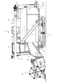
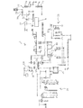
図1〜図3は、それぞれ、本発明の一実施形態に係るコンバイン1の側面図、平面図及び伝動模式図である。
Hereinafter, preferred embodiments of the present invention will be described with reference to the accompanying drawings.
1 to 3 are a side view, a plan view, and a transmission schematic diagram of a combine 1 according to an embodiment of the present invention, respectively.
図1〜図3に示すように、前記コンバイン1は、走行機体2と、前記走行機体2に支持された駆動源としてのエンジン9と、前記走行機体2に連結された左右一対の走行装置(本実施形態においては、クローラ式走行装置)10と、HSTを含み、前記エンジン9からの回転動力を変速して前記一対の走行装置10へ出力する走行系トランスミッション100と、前記走行機体2の前方において該走行機体2に支持された刈取装置(本実施形態においては、刈取リール)30と、前記刈取装置30によって刈り取られた穀稈を後方へ搬送するフィードチェーン装置20と、前記フィードチェーン装置20によって搬送される穀稈に対して脱穀処理を行うように、前記エンジン9から作動的に入力される定速動力により回転駆動する扱胴(本実施形態においては、車輌前後方向に回転軸41を有し、当該回転軸41回りに螺旋状の扱歯を有するロータ型扱胴)42を有し、前記走行機体2の左部分に配設された脱穀装置40と、前記脱穀装置40の下方に配設された揺動選別装置50と、前記エンジン9から作動的に定速動力を入力して、前記刈取装置30、前記フィードチェーン装置20及び前記揺動選別装置50を含む作業機に向けて回転動力を出力する作業機系トランスミッション200と、前記走行機体2の右前方部分に配設された運転席5と、前記揺動選別装置50によって選別された穀粒を収容するグレンタンク6であって、前記運転席5の後方に配設されたグレンタンク6と、前記グレンタンク6の後部から延出され、グレンタンク6内の穀粒を外部に排出する排出オーガ7とを備えている。
As shown in FIGS. 1 to 3, the combine 1 includes a traveling machine body 2, an
前記作業機系トランスミッション200から前記刈取装置30へ至る伝動経路には、刈取クラッチ31が介挿されており、前記刈取クラッチ31を係脱させることにより、前記作業機系トランスミッション200の回転出力を前記作業機に向けて伝達又は遮断する。
また、前記エンジン9から前記脱穀装置45へ至る伝動経路には、脱穀クラッチ45が介挿されており、前記脱穀クラッチ45を係脱させることにより、前記エンジン9の定速回転動力を前記脱穀装置45の扱胴42の回転軸41に伝達又は遮断する。
さらに、前記エンジン9から前記排出オーガ7へ至る伝動経路には、穀粒排出クラッチ71が介挿されており、前記穀粒排出クラッチ71を係脱させることにより、前記エンジン9の定速回転動力を前記排出オーガ7に伝達又は遮断する。
上記各クラッチ31,45,71は、それぞれ前記伝動経路に介挿された伝動プーリ対に巻回された伝動ベルト32,46,72に対してテンションを付加/解除させることで、動力伝達を係合又は遮断させ得るように構成されている。
A mowing clutch 31 is inserted in a transmission path from the
Further, a threshing clutch 45 is inserted in a transmission path from the
Further, a
Each of the
ここで、前記コンバイン1における排出オーガ7の構成について説明する。
排出オーガ7は、グレンタンク6の後部に略垂直に立設され、基端部がグレンタンク6の後方下部の排出口73(後述する図5参照)と連通された縦排出オーガ筒7aと、前記縦排出オーガ筒7aに対して略垂直(走行機体2に対して略水平)に配置され、基端部が前記縦排出オーガ筒7aの先端部と連通し且つ自由端部が穀粒の放出口7cとされ、前記縦排出オーガ筒7aの軸線回りに旋回可能且つ上下方向に揺動可能な上部排出オーガ筒7bとを備えている。
Here, the configuration of the discharge auger 7 in the combine 1 will be described.
The discharge auger 7 is erected substantially vertically at the rear part of the Glen
本実施形態のコンバイン1は、グレンタンク6に蓄積された穀粒を排出オーガ7の放出口7cへ導くために、前記穀粒排出クラッチ71及び前記伝動ベルト72を介してエンジン9に作動連結された状態で前記グレンタンク6の底部に配設された下部コンベア73であって、前記グレンタンク6に設けられた前記排出口73へ向けて穀粒を搬送する下部コンベア74と、前記下部コンベア74の搬送終端側に作動連結された状態で前記縦排出オーガ筒7aに内挿された縦コンベア75であって、前記下部コンベア74によって搬送されてくる穀粒を前記縦排出オーガ筒7a内において上方へ搬送する縦コンベア75と、前記縦コンベア75に作動連結された状態で前記上部オーガ筒7bに内挿された上部コンベア76であって、前記縦コンベア75によって搬送されてくる穀粒を前記上部オーガ筒7bの前記放出口7cへ向けて搬送する上部コンベア76とを有している。
The combine 1 of this embodiment is operatively connected to the
また、前記コンバイン1は、前記下部コンベア74の搬送始端側に搬送風を送風し得る圧風ファン77を備えている。
前記圧風ファン77は、前記穀粒排出クラッチ71及び前記伝動ベルト72を介してエンジン9に作動連結される。さらに、本実施形態において、前記コンバイン1は、前記穀粒排出クラッチ71及び伝達ベルト72の伝動経路下流側にファン起動クラッチ78が介挿されている。前記ファン起動クラッチ78も他の前記クラッチ31,45,71と同様に、伝動経路に介挿された伝動プーリ対に巻回された伝動ベルト79に対してテンションを付加/解除させることで、動力伝達を係合又は遮断させ得るように構成されている。
Further, the combine 1 is provided with a
The
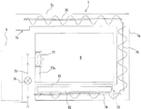
図4から図6に、図1のコンバイン1におけるグレンタンク6の前方断面図、側方断面図及び背面図を示す。また、図7に、図1のコンバイン1における穀粒排出制御系の概略ブロック図を示す。
本実施形態のコンバイン1は、図4から図6に示すように、前記下部コンベア74の上方において前記下部コンベア74に沿うように前記グレンタンク6内に配設された傘体81であって、前記下部コンベア74の軸線方向に垂直な断面略逆V字状の傘体81と、前記傘体81に設けられたシャッタ部材82とを備えている。
即ち、前記傘体81は、上面視において前記下部コンベア74の軸線と略一致する中央部から上面視において前記下部コンベア74の軸線から離間する方向へ行くに従って下方に位置するように構成されている。
4 to 6 are a front sectional view, a side sectional view, and a rear view of the
As shown in FIGS. 4 to 6, the combine 1 of the present embodiment is an
That is, the
本実施形態において、前記グレンタンク6は、正面視において略垂直に延びる左右一対の上部側壁6aと、前記左右一対の上部側壁6aからそれぞれ下方へ延び、下端部に前記下部コンベア74が収容されるコンベア領域A1を有する左右一対の下部側壁6bであって、下方へ行くに従って相対する側壁が互いに近接する下部側壁6bとを有する。さらに、前記グレンタンク6は、前記コンベア領域A1において、前記下部コンベア74の側方及び下方を囲繞するように形成されたコンベア収容側壁6cであって、上端部が前記左右一対の下部側壁6bの下端部のそれぞれと結合されているコンベア収容側壁6cを有している。
前記傘体81は、左右の傾斜面のそれぞれが前記下部側壁6bに対して略直交する向きに配設されており、前記下部コンベア74は、前記コンベア収容上部側壁6c及び前記傘体81により囲まれたコンベア領域A1内に配設されている。
In the present embodiment, the
The left and right inclined surfaces of the
本実施形態において、前記シャッタ部材82は、前記傘体81の左右の傾斜面上をそれぞれ摺動可能に構成されている。そして、前記シャッタ部材82は、図4に示すように、前記グレンタンク6の下部側壁6bに近接した位置に移動することにより前記傘体81との共働下に前記グレンタンク6の内部空間を前記コンベア領域A1及び前記コンベア領域A1より上方の本体領域A2に分離する遮蔽状態(破線にて示す)と、前記グレンタンク6の下部側壁6bから離間した位置に移動することにより前記本体領域A2から前記コンベア領域A1への穀粒の流れを許容する開放状態(実線にて示す)とを選択的にとり得るように構成されている。
In the present embodiment, the
本実施形態において、前記圧風ファン77は、図5に示すように、回転軸線が前記下部コンベア74の軸線と略平行に配置した状態で、前記運転席5と前記グレンタンク6との間に配設されている。さらに、前記圧風ファン77は、図6に示すように、背面視において前記グレンタンク6の内側に配設されている。より具体的には、前記圧風ファン77は、回転軸線が前記下部コンベア74の軸線より背面視斜め上方に位置している。即ち、前記圧風ファン77からの搬送風は、搬送路77aを介して前記下部コンベア74の搬送始端側の斜め上方から前記コンベア領域A1内へ導入される。
In the present embodiment, as shown in FIG. 5, the
このように、圧風ファン77は、運転席5とグレンタンク6との間のデッドスペースに配設される。従って、圧風ファン77を設けることによるコンバイン1の大型化を防止することができる。
Thus, the
また、本実施形態において、前記コンバイン1は、前記グレンタンク6の穀粒貯留量を検出する穀粒量センサ91を備えている。
前記穀粒量センサ91は、図4に示すように、前記グレンタンク6の下部側壁6bに設けられたロードセル型の重量センサが用いられている。
なお、穀粒量センサ91は、上記例に限られず、例えば、グレンタンク6の外部下方に設けられ、グレンタンク6全体の総重量を計測する重量センサや、前記下部側壁6bに設けられた赤外線センサ等、グレンタンク6の内容量を検知可能なセンサであればよい。
Further, in the present embodiment, the combine 1 includes a
As shown in FIG. 4, a load cell type weight sensor provided on the
The
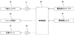
また、前記コンバイン1は、図7に示すように、外部操作信号に基づき前記穀粒排出クラッチ71を係脱させるとともに、前記圧風ファン77及び前記シャッタ部材82の作動制御を行う制御装置90を備えている。
さらに、前記コンバイン1は、人為操作可能な穀粒排出スイッチ92を備えており、前記制御装置90は、前記穀粒排出スイッチ92の操作に応じて前記穀粒排出クラッチ71の係脱を切り替え作動させるように構成されている。
Further, as shown in FIG. 7, the combine 1 engages / disengages the grain discharge clutch 71 based on an external operation signal, and includes a
Furthermore, the combine 1 is provided with a
本実施形態において、前記制御装置90は、圧風ファン77を駆動させる際には前記シャッタ部材82を遮蔽状態とさせるように構成されている。
より詳しくは、前記制御装置90は、外部操作信号に基づき前記圧風ファン77を停止状態とした上で前記穀粒排出クラッチ71を係合させる通常穀粒排出モードと、通常穀粒排出モード作動中において前記穀粒量センサ91からの信号に基づき穀粒貯留量が所定値を下回ると前記圧風ファン77を駆動させ且つ前記シャッタ部材82を遮蔽状態とする残留穀粒排出モードとを有している。
In the present embodiment, the
More specifically, the
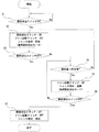
図8に、本実施形態における穀粒排出に関する制御フロー図を示す。
上記のように、本実施形態においては、前記穀粒量センサ91により、グレンタンク6内の穀粒の貯留量(以下、単に穀粒量と称する)が検出され、前記制御装置90に信号送信される。
図8に示すように、作業者が前記穀粒排出スイッチ92を操作すると(ステップS1)、前記制御装置90は、前記穀粒排出スイッチ92からの操作信号を受信して、前記穀粒排出クラッチを係合させる(ON状態とさせる)べく、前記穀粒排出クラッチ71に対し制御信号を送信する(ステップS2)。このとき、前記ファン起動クラッチ78は遮断状態(OFF状態)且つ前記シャッタ部材82は開放状態となっている。
In FIG. 8, the control flowchart regarding the grain discharge | emission in this embodiment is shown.
As described above, in this embodiment, the
As shown in FIG. 8, when an operator operates the grain discharge switch 92 (step S1), the
従って、前記穀粒排出クラッチ71が係合することにより、下部コンベア74、縦コンベア75及び上部コンベア76が駆動する通常穀粒排出モードが実行される。
前記通常穀粒排出モードにおいては、グレンタンク6の底部に配設された下部コンベア74が作動することにより、グレンタンク6に収容されている穀粒が排出口73へ向けて搬送される。下部コンベア74によりグレンタンク6から前記排出口73を通じて排出された穀粒は、前記下部コンベア74に作動連結された縦コンベア75及び上部コンベア76を介して上部コンベア76が内挿される上部オーガ筒7bの放出口7cから機外へ放出される。
前記グレンタンク6内の下部コンベア74の上方に、当該下部コンベア74に沿うように設けられている前記傘体81は、前記下部コンベア74の軸線方向に垂直な断面略逆V字状とされるため、前記傘体81の上方から落下してくる穀粒は、当該傘体81によりグレンタンク6の両側壁(下部側壁6b)へ向けて分配されることにより均等化される。
Accordingly, when the
In the normal grain discharge mode, the
The
前記通常穀粒排出モードは、前記穀粒排出スイッチ92が再操作されて前記穀粒排出クラッチ71が遮断される(ステップS3でYes)か、前記穀粒量センサ91により検出される穀粒量が所定値を下回る(ステップS4でYes)まで継続される。
In the normal grain discharge mode, the
前記穀粒量センサ91により検出される穀粒量が所定値を下回った場合(ステップS4でYes)、前記制御装置90は、前記シャッタ部材82を開放状態から遮蔽状態へと移動させるとともに、前記ファン起動クラッチ78を係合させる(ON状態とさせる)残留穀粒排出モードに移行する(ステップS5)。このとき、前記穀粒排出クラッチ71の係合は維持されるため、前記下部コンベア74、前記縦コンベア75及び前記上部コンベア76の駆動は維持される。
これにより、前記傘体81及び前記シャッタ部材82により前記コンベア領域A1が前記本体領域A2に対して分離した状態で、圧風ファン77による搬送風が下部コンベア74の搬送始端側から搬送終端側(即ち、グレンタンク6の排出口73)へ向けて送風される。
When the grain amount detected by the
Thereby, in a state where the conveyor area A1 is separated from the main body area A2 by the
前記残留穀粒排出モードは、前記穀粒排出スイッチ92が再操作されて前記穀粒排出クラッチ71が遮断される(ステップS6でYes)か、前記穀粒量センサ91により検出される穀粒量が所定値以上となる(ステップS4でNo)まで継続される。
前記通常穀粒排出モード(ステップS2)又は残留穀粒排出モード(ステップS5)において、穀粒排出スイッチ92が再操作され、OFF状態となると(ステップS3又はS6でNo)、前記制御装置90は、前記穀粒排出クラッチ71及び前記ファン起動クラッチ78を遮断する(OFF状態にする)とともに、前記シャッタ部材82を開放状態に移動させる(ステップS7)。
In the residual grain discharge mode, the
In the normal grain discharge mode (step S2) or the residual kernel discharge mode (step S5), when the
このように、圧送ファン77の駆動時においてはシャッタ部材82が遮蔽状態となることにより、コンベア領域A1及び本体領域A2が分離されるため、圧送ファン77の搬送風を上方へ吹き上がらせることを防止して下部コンベア74の搬送終端側に効率的に送風することができる。
従って、圧送ファン77駆動時に下部コンベア74の近傍で残留する穀粒がグレンタンク6内に拡散されることなく、搬送風によって残留穀粒を効率的に排出することができる。
また、穀粒量センサ92により検出される穀粒量に基づいて残留穀粒排出モードへの移行を自動制御することにより、グレンタンク6の穀粒貯留量が所定値より少なくなり、排出効率が低下し易い状況となった場合に、圧風ファン77の駆動を開始するとともにシャッタ部材82を遮蔽状態とすることができ、自動的に排出効率を高めることができる。
As described above, when the
Therefore, the residual grain can be efficiently discharged by the conveying air without the grain remaining in the vicinity of the
In addition, by automatically controlling the transition to the residual grain discharge mode based on the grain quantity detected by the
なお、本実施形態においては、穀粒量センサ92により検出される穀粒量に基づいて自動的に残留穀粒排出モードへ移行することとしているが、これに加えて、又はこれに代えて、人為操作可能なファン起動スイッチ(図示せず)を備え、前記制御装置90が前記ファン起動スイッチの操作に応じて前記ファン起動クラッチ78の係脱を切り替え作動させるように構成されることとしてもよい。
In the present embodiment, the automatic transition to the residual grain discharge mode is made based on the grain quantity detected by the
また、前記遮蔽状態の分離態様は、前記コンベア領域A1と本体領域A2とが完全に分離する(傘体81及びシャッタ部材82によって前記2つの領域が画される)態様であってもよいし、前記遮蔽状態において前記傘体81及びシャッタ部材82によって前記コンベア領域A1と本体領域A2とが隔てられる領域が開放状態における前記領域より大きいとする態様であってもよい。即ち、前記遮蔽状態において、前記コンベア領域A1と本体領域A2との間で連通する領域が存在していてもよい。
Further, the separation state in the shielding state may be a state in which the conveyor region A1 and the main body region A2 are completely separated (the two regions are defined by the
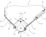
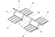
本実施形態において、前記傘体81の下方且つ前記下部コンベア74の上方には、図4に示すように、グレンタンク6内を揺動軸83a回り揺動可能に配設された揺動フレーム83と、基端部が前記揺動フレームに支持されたスイングプレート84とを有する揺動機構85が設けられている。
図9に、本実施形態における揺動機構85の斜視組立図を示す。
前記スイングプレート84は、図4及び図9に示すように、前記揺動フレーム83の揺動軸83aと略平行な軸線回りに揺動自在とされており、前記スイングプレート84の他端部は、前記揺動フレーム83の軸線回りの揺動に応じて前記グレンタンク6内の下部側壁6b面上を摺動可能とされている。
In the present embodiment, as shown in FIG. 4, a
FIG. 9 shows a perspective assembly view of the
4 and 9, the
本実施形態において、前記揺動フレーム83の揺動軸83aは、前記エンジン9に作動連結されており、前記揺動フレーム83が前記揺動軸83a回りに揺動することにより、前記スイングプレート84の自由端部が前記下部側壁6b面上を摺動する。
これにより、前記グレンタンク6の下部側壁6b面上の穀粒を振動させて、前記下部コンベア74(コンベア領域A1)に向けて穀粒の落下を促進させることができ、前記下部側壁6b面上において穀粒が残留することを有効に防止することができる。
In the present embodiment, the
Thereby, the grain on the surface of the
なお、本実施形態の揺動機構85においては、図9に示すように、前記揺動軸83aから左右に張り出した複数の揺動フレーム83と、複数の前記スイングプレート84を有し、前記複数のスイングプレート84は、それぞれ、前記複数のフレーム83のうち前記揺動軸83a方向に隣り合う一対の揺動フレーム83に両端部が前記揺動軸83aと略平行な軸線回りに揺動自在に連結されている。このようにして、前記複数のスイングプレート84は、揺動軸83aに直交する方向へ左右一対且つ揺動軸83a方向へ所定間隔離間した状態で複数組配設されている。
As shown in FIG. 9, the
以上、本発明に係る実施の形態を説明したが、本発明は上記実施の形態に限定されるものではなく、その趣旨を逸脱しない範囲内で種々の改良、変更、修正が可能である。 The embodiment according to the present invention has been described above, but the present invention is not limited to the above embodiment, and various improvements, changes, and modifications can be made without departing from the spirit of the present invention.
図10に、本発明に係る他の実施形態におけるグレンタンク6の背面図を示す。
上記実施形態においては、前記シャッタ部材82が前記傘体81の左右の傾斜面上をそれぞれ摺動可能に構成されている例について説明したが、これに限られず、例えば、図10に示すように、前記シャッタ部材82は、前記傘体81の左右両端部近傍において、それぞれ前記揺動軸83aに略平行な軸線回りに回動可能に配設されることとしてもよい。この場合、シャッタ部材82は、前記揺動軸83aに略平行な軸線回りに回動することにより、前記遮蔽状態(図10において破線で示す)及び前記開放状態(図10において実線で示す)が切り替えられる。
In FIG. 10, the rear view of the
In the above-described embodiment, the example in which the
また、上記実施形態においては、前記圧風ファン77が背面視において前記グレンタンク6の内側に配設されている例について説明したが、これに限られず、例えば、図10に示すように、前記圧風ファン77は、背面視において前記グレンタンク6の外側且つ前記下部側壁6bの下方に配設されていてもよい。この場合、前記圧風ファン77からの搬送風は、前記下部コンベア74の搬送始端側のコンベア収容側壁6cから前記コンベア領域A1内へ導入される。なお、この場合には、前記グレンタンク6内に、前記圧風ファン77の不使用時において圧風ファン77及び前記コンベア領域A1間を連結する搬送路77aと前記グレンタンク6のコンベア領域A1とを遮蔽可能な送風弁77bを設けることが好ましい。これにより、前記圧風ファン77の不使用時においては送風弁77bを遮蔽状態とすることでグレンタンク6内の穀粒が前記圧風ファン77の搬送路77aに進入し残留することを防止することができる。
Moreover, in the said embodiment, although the said
1 コンバイン
5 運転席
6 グレンタンク
7a 縦排出オーガ筒
7b 上部オーガ筒
7c 放出口
9 エンジン(駆動源)
71 穀粒排出クラッチ
73 排出口
74 下部コンベア
75 縦コンベア
76 上部コンベア
77 圧風ファン
81 傘体
82 シャッタ部材
90 制御装置
91 穀粒量センサ
A1 コンベア領域
A2 本体領域
1 Combine 5 Driver's
71 Grain discharge clutch 73
Claims (3)
前記傘体に設けられたシャッタ部材と、外部操作信号に基づき前記穀粒排出クラッチを係脱させるとともに、前記圧風ファン及び前記シャッタ部材の作動制御を行う制御装置と、前記グレンタンクの穀粒貯留量を検出する穀粒量センサとを備え、
前記シャッタ部材は、前記傘体との共働下に前記グレンタンクの内部空間を前記下部コンベアが収容されるコンベア領域及び前記コンベア領域より上方の本体領域に分離する遮蔽状態と、前記本体領域から前記コンベア領域への穀粒の流れを許容する開放状態とを選択的にとり得るように構成されており、
前記制御装置は、外部操作信号に基づき前記圧風ファンを停止状態とした上で前記穀粒排出クラッチを係合させる通常穀粒排出モードと、通常穀粒排出モード作動中において前記穀粒量センサからの信号に基づき穀粒貯留量が所定値を下回ると前記圧風ファンを駆動させ且つ前記シャッタ部材を遮蔽状態とする残留穀粒排出モードとを有していることを特徴とするコンバイン。 A grain tank for storing grains, and a lower conveyor disposed at the bottom of the grain tank in a state of being operatively connected to a drive source via a grain discharge clutch, and an outlet provided in the grain tank A lower conveyor that conveys the grain toward the head, an umbrella body that is disposed in the Glen tank so as to follow the lower conveyor above the lower conveyor, and a conveyance wind is blown to the conveyance start end side of the lower conveyor A combine with a wind fan that can
A shutter member provided on the umbrella body, a control device for engaging and disengaging the grain discharge clutch based on an external operation signal, and controlling the operation of the compressed air fan and the shutter member, and grain of the Glen tank A grain amount sensor for detecting the storage amount ,
The shutter member, in cooperation with the umbrella, separates the internal space of the Glen tank into a conveyor area in which the lower conveyor is accommodated and a main body area above the conveyor area, and from the main body area. It is configured to be able to selectively take an open state that allows the flow of grain to the conveyor area ,
The control device includes a normal grain discharge mode in which the compressed air fan is stopped based on an external operation signal and then the grain discharge clutch is engaged, and the grain amount sensor during normal grain discharge mode operation. And a residual grain discharging mode in which the compressed air fan is driven and the shutter member is shielded when the amount of stored grain falls below a predetermined value based on a signal from .
前記傘体に設けられたシャッタ部材と、外部操作信号に基づき前記穀粒排出クラッチを係脱させるとともに、前記圧風ファン及び前記シャッタ部材の作動制御を行う制御装置と、人為操作可能なファン起動スイッチとを備え、
前記シャッタ部材は、前記傘体との共働下に前記グレンタンクの内部空間を前記下部コンベアが収容されるコンベア領域及び前記コンベア領域より上方の本体領域に分離する遮蔽状態と、前記本体領域から前記コンベア領域への穀粒の流れを許容する開放状態とを選択的にとり得るように構成されており、
前記制御装置は、外部操作信号に基づき前記圧風ファンを停止状態とした上で前記穀粒排出クラッチを係合させる通常穀粒排出モードと、通常穀粒排出モード作動中において前記ファン起動スイッチが操作されると前記圧風ファンを駆動させ且つ前記シャッタ部材を遮蔽状態とする残留穀粒排出モードとを有していることを特徴とするコンバイン。 A grain tank for storing grains, and a lower conveyor disposed at the bottom of the grain tank in a state of being operatively connected to a drive source via a grain discharge clutch, and an outlet provided in the grain tank A lower conveyor that conveys the grain toward the head, an umbrella body that is disposed in the Glen tank so as to follow the lower conveyor above the lower conveyor, and a conveyance wind is blown to the conveyance start end side of the lower conveyor A combine with a wind fan that can
A shutter member provided in front Kikasa body, together with the disengaging said grain discharge clutch based on an external operation signal, and a control device that performs operation control of the圧風fan and said shutter member, human operable fan With a start switch ,
The shutter member, in cooperation with the umbrella, separates the internal space of the Glen tank into a conveyor area in which the lower conveyor is accommodated and a main body area above the conveyor area, and from the main body area. It is configured to be able to selectively take an open state that allows the flow of grain to the conveyor area,
The control device includes a normal grain discharge mode in which the compressed air fan is stopped based on an external operation signal and the grain discharge clutch is engaged, and the fan start switch is activated during normal grain discharge mode operation. features and to Turkey Nbain that an engineered Ru said圧風and said shutter member to drive the fan and a residual grain discharge mode to blocking state.
Priority Applications (1)
| Application Number | Priority Date | Filing Date | Title |
|---|---|---|---|
| JP2008084155A JP5259222B2 (en) | 2008-03-27 | 2008-03-27 | Combine |
Applications Claiming Priority (1)
| Application Number | Priority Date | Filing Date | Title |
|---|---|---|---|
| JP2008084155A JP5259222B2 (en) | 2008-03-27 | 2008-03-27 | Combine |
Publications (2)
| Publication Number | Publication Date |
|---|---|
| JP2009232776A JP2009232776A (en) | 2009-10-15 |
| JP5259222B2 true JP5259222B2 (en) | 2013-08-07 |
Family
ID=41247529
Family Applications (1)
| Application Number | Title | Priority Date | Filing Date |
|---|---|---|---|
| JP2008084155A Expired - Fee Related JP5259222B2 (en) | 2008-03-27 | 2008-03-27 | Combine |
Country Status (1)
| Country | Link |
|---|---|
| JP (1) | JP5259222B2 (en) |
Families Citing this family (2)
| Publication number | Priority date | Publication date | Assignee | Title |
|---|---|---|---|---|
| EP2562255A4 (en) | 2010-04-21 | 2013-10-30 | Riken | BASIC ANALOGUE OF NUCLEIC ACID WITH CHARACTERISTICS OF COOLING AND FLUORESCENCE AND APPLICATION THEREOF |
| CN102884914B (en) * | 2012-10-19 | 2015-06-24 | 郑州中联收获机械有限公司 | Corn harvester and grain bin of corn harvester |
Family Cites Families (4)
| Publication number | Priority date | Publication date | Assignee | Title |
|---|---|---|---|---|
| JPS5722515Y2 (en) * | 1976-04-16 | 1982-05-15 | ||
| JPS63145435U (en) * | 1987-03-16 | 1988-09-26 | ||
| JPH0585231U (en) * | 1992-04-20 | 1993-11-19 | 三菱農機株式会社 | Combined paddy tank shutter device |
| JPH10313668A (en) * | 1997-05-20 | 1998-12-02 | Kubota Corp | Harvester |
-
2008
- 2008-03-27 JP JP2008084155A patent/JP5259222B2/en not_active Expired - Fee Related
Also Published As
| Publication number | Publication date |
|---|---|
| JP2009232776A (en) | 2009-10-15 |
Similar Documents
| Publication | Publication Date | Title |
|---|---|---|
| JP5731938B2 (en) | Combine | |
| JP5259222B2 (en) | Combine | |
| JP6284027B2 (en) | Transmission device for waste cutter in combine | |
| JP5353737B2 (en) | Combine | |
| JP2013048565A (en) | Combine | |
| JP6226303B2 (en) | Combine | |
| CN107426969A (en) | Sheller unit | |
| JP6454173B2 (en) | Combine | |
| JP3858620B2 (en) | Kernel transport device | |
| JP6245765B2 (en) | Combine | |
| JP2013123416A (en) | Grain unloading structure of combine harvester | |
| JP4096498B2 (en) | Combine | |
| JP2008125431A (en) | Combine | |
| JP2010187641A (en) | Combined harvester | |
| JP2005237337A (en) | Combine | |
| JP4420160B2 (en) | Combine | |
| JP2841293B2 (en) | Threshing equipment | |
| JP6775459B2 (en) | combine | |
| JP2015188438A (en) | Combine | |
| JP2002171825A (en) | Combine grain discharger | |
| JP2005348678A (en) | Load alarm system of thresher | |
| KR100401271B1 (en) | Grain conveyor | |
| JP6594830B2 (en) | Combine | |
| TW202517135A (en) | Combine harvester | |
| JP3918756B2 (en) | Pneumatic grain conveyor |
Legal Events
| Date | Code | Title | Description |
|---|---|---|---|
| A621 | Written request for application examination |
Free format text: JAPANESE INTERMEDIATE CODE: A621 Effective date: 20110201 |
|
| A977 | Report on retrieval |
Free format text: JAPANESE INTERMEDIATE CODE: A971007 Effective date: 20120622 |
|
| A131 | Notification of reasons for refusal |
Free format text: JAPANESE INTERMEDIATE CODE: A131 Effective date: 20120706 |
|
| A521 | Written amendment |
Free format text: JAPANESE INTERMEDIATE CODE: A523 Effective date: 20120820 |
|
| TRDD | Decision of grant or rejection written | ||
| A01 | Written decision to grant a patent or to grant a registration (utility model) |
Free format text: JAPANESE INTERMEDIATE CODE: A01 Effective date: 20130405 |
|
| A61 | First payment of annual fees (during grant procedure) |
Free format text: JAPANESE INTERMEDIATE CODE: A61 Effective date: 20130424 |
|
| FPAY | Renewal fee payment (event date is renewal date of database) |
Free format text: PAYMENT UNTIL: 20160502 Year of fee payment: 3 |
|
| R150 | Certificate of patent or registration of utility model |
Free format text: JAPANESE INTERMEDIATE CODE: R150 |
|
| S531 | Written request for registration of change of domicile |
Free format text: JAPANESE INTERMEDIATE CODE: R313531 |
|
| R350 | Written notification of registration of transfer |
Free format text: JAPANESE INTERMEDIATE CODE: R350 |
|
| LAPS | Cancellation because of no payment of annual fees |