JP5243879B2 - Side brush support device for cleaning robot - Google Patents
Side brush support device for cleaning robot Download PDFInfo
- Publication number
- JP5243879B2 JP5243879B2 JP2008201275A JP2008201275A JP5243879B2 JP 5243879 B2 JP5243879 B2 JP 5243879B2 JP 2008201275 A JP2008201275 A JP 2008201275A JP 2008201275 A JP2008201275 A JP 2008201275A JP 5243879 B2 JP5243879 B2 JP 5243879B2
- Authority
- JP
- Japan
- Prior art keywords
- side brush
- swing
- retracting
- support device
- width direction
- Prior art date
- Legal status (The legal status is an assumption and is not a legal conclusion. Google has not performed a legal analysis and makes no representation as to the accuracy of the status listed.)
- Active
Links
Images


Description
本発明は、床面等を清掃する清掃ロボットのサイドブラシ支持装置に関する。 The present invention relates to a side brush support device for a cleaning robot that cleans floor surfaces and the like.
近年、自律走行機能と床面清掃機能とを有する清掃ロボットが開発されている。 In recent years, a cleaning robot having an autonomous running function and a floor surface cleaning function has been developed.
この種の床面等を清掃する清掃ロボットに関しては、例えば特許文献1がある。この特許文献1の清掃ロボットは、自律走行が可能なようにロボット本体の下面にモータによって駆動される左右の駆動輪及びキャスタと、障害物や方位等の検知を行うセンサを有し、各センサの出力を用いてモータの動作を制御するマイクロコンピュータを備える。ロボット本体の下面には床面清掃が可能なようにパワーブラシモータによって回転駆動する円筒状のパワーブラシ及び塵埃を吸引収容するダストボックスの吸引口を設け、更にロボット本体の前部左右にやや拡開しながら延出する2本のアーム部にサイドブラシモータによって回転駆動する円錐台形状のサイドブラシを設ける。
For example,
そして、予め設定されたプログラムに従って回転駆動される駆動輪によって走行しつつ、回転するサイドブラシにより左右の塵埃を内側へ掃き寄せると共に、回転するパワーブラシによって掃き出された塵埃を吸引口からダストボックス内に吸引する。 Then, while traveling with the driving wheel that is driven to rotate according to a preset program, the left and right dusts are swept inward by the rotating side brush, and the dust swept by the rotating power brush is drawn from the suction port into the dust box. To suck.
また、特許文献2には、走行中において床面上の障害物や床面の段差等を検出し、その検出に基づいてサイドブラシやパワーブラシの回転や高さを制御する清掃ロボットが開示されている。
しかし、特許文献1にあってはロボット本体から延出するアーム部の先端部にサイドブラシを備えることから、サイドブラシにより壁際等の清掃を行う際に、清掃ロボットが壁際に寄りすぎてサイドブラシが障害物や壁面に衝突することがある。同様に、引用文献2には、サイドブラシがロボット本体から突出してロボット本体に支持されることから、サイドブラシにより壁際等の清掃を行う際に清掃ロボットが壁際に寄りすぎてサイドブラシが障害物や壁面に衝突することがある。
However, in
サイドブラシが障害物や壁面に衝突すると、サイドブラシ或いはサイドブラシを支持するアーム部やロボット本体のサイドブラシ支持部が破損することが懸念される。また、円滑な清掃ロボットによる床面清掃が妨げられるおそれがある。このため壁際からある程度余裕を持った状態で床面清掃を行うと、清掃残し等を招くことになる。 When the side brush collides with an obstacle or a wall surface, there is a concern that the side brush or the arm portion that supports the side brush or the side brush support portion of the robot body may be damaged. Moreover, there is a possibility that the floor cleaning by the smooth cleaning robot may be hindered. For this reason, if floor cleaning is performed with a certain margin from the wall, uncleaning or the like will be caused.
従って、かかる点に鑑みなされた本発明の目的は、清掃ロボットが壁際等に寄りすぎてサイドブラシが障害物や壁面に衝突してもサイドブラシやその支持装置等の破損を招くことがなく円滑な床面清掃が得られる清掃ロボットのサイドブラシ支持装置を提供することにある。 Therefore, the object of the present invention made in view of such a point is to prevent the side brush and its supporting device from being damaged even if the cleaning robot is too close to the wall or the like and the side brush collides with an obstacle or a wall surface. Another object of the present invention is to provide a side brush support device for a cleaning robot that can obtain a clean floor surface.
上記目的を達成する請求項1に記載の清掃ロボットのサイドブラシ支持装置の発明は、走行部を備えたロボット本体の下面にサイドブラシ支持装置を介して該ロボット本体から幅方向外方でかつ前方に突出した状態に支持されると共に、回転駆動されて床面の塵埃をロボット本体の幅方向内方に掃き寄せるサイドブラシを有する清掃部を備えた清掃ロボットのサイドブラシ支持装置において、基端が第1揺動軸を介して上下方向に揺動自在にロボット本体の下面に支持されて前方に延出する昇降揺動部材と、該昇降揺動部材に基部が第2揺動軸を介して幅方向に揺動自在に連結されて前方に延出する第1揺動部材と、上記昇降揺動部材に対する第1揺動部材の幅方向外方及び内方の揺動端をそれぞれ使用位置と格納位置とに規制する第1揺動部材揺動端規制手段と、上記第1揺動部材の先端に基端部が第3揺動軸を介して幅方向に揺動自在に連結されて前方に延在する先端部にサイドブラシモータによって回転駆動されるサイドブラシを保持するサイドブラシモータカバーを支持する第2揺動部材と、上記第1揺動部材に対する第2揺動部材の幅方向外方及び内方の揺動端をそれぞれ使用位置と格納位置に規制する第2揺動部材揺動端規制手段と、上記第1揺動部材を上方から吊り下げる昇降動作牽引索及び該昇降動作牽引索を繰り出して上記第1揺動部材が下降した使用位置と牽引して上昇した格納位置との間で昇降揺動させる昇降用牽引アクチュエータと、上記サイドブラシモータカバーに先端が連結される格納動作牽引索及び該格納動作牽引索を使用位置に繰り出して上記第2揺動部材の揺動を許容する一方、格納位置に牽引してサイドブラシモータカバーを格納位置に保持する格納用牽引アクチュエータと、を備え、上記格納用牽引アクチュエータによる格納動作牽引索の使用位置への繰り出しにより上記第2揺動部材の揺動許容をして上記昇降用牽引アクチュエータによる昇降動作牽引索の使用位置への繰り出しによる上記第1揺動部材の使用位置において床面に接触するサイドブラシの回転に伴う床面からの反力により上記第1揺動部材及び第2揺動部材を幅方向外方に付勢する一方、昇降用牽引アクチュエータによる昇降動作牽引索の格納位置への牽引及び格納用牽引アクチュエータによる格納動作牽引索の格納位置への牽引でサイドブラシが床面から上昇した状態でロボット本体の下方に収納されることを特徴とする。
The invention of a side brush support device for a cleaning robot according to
この発明によると、昇降用牽引アクチュエータにより昇降動作牽引索を使用位置に繰り出して第1揺動部材が下降揺動すると共に格納用牽引アクチュエータにより格納動作牽引索を使用位置に繰り出して第2揺動部材の揺動を許容してサイドブラシを床面に接触させると、サイド部材の回転に伴う床面からの反力で第2揺動部材及び第1揺動部材が揺動してそれぞれ第1揺動部材揺動規制手段及び第2揺動部材揺動規制手段により使用位置に保持されてサイドブラシによる良好な清掃作業が行われる。 According to the present invention, the first lifting member is lowered and swung by the lifting traction actuator to the use position, and the retracting traction actuator is moved to the second position by the storage traction actuator. When the side brush is brought into contact with the floor surface while allowing the member to swing, the second swinging member and the first swinging member swing due to the reaction force from the floor surface accompanying the rotation of the side member. The swinging member swinging restricting means and the second swinging member swinging restricting means are held at the use position and a good cleaning operation is performed with the side brush.
また、清掃作業においてサイドブラシが壁面や障害物に接触して外力がサイドブラシに作用した際には、サイドブラシに作用する床面から反力による幅方向外方側への付勢力に抗して第2揺動支持部材が幅方向内方に揺動してサイドブラシが壁面等から退避し、外力付与がなくなると復帰することから、サイドブラシ及びサイドブラシ支持装置等に過剰な力が加わるのが防止され、サイドブラシやサイドブラシ支持装置の破損が確実に回避される。その結果、サイドブラシ及びサイドブラシ支持装置等の破損を考慮することなく、清掃ロボットを壁際近傍に寄せた状態で清掃作業を行うことができ、良好な清掃作業を確保できる。 Also, when the side brush comes into contact with the wall or an obstacle during cleaning work and an external force acts on the side brush, it resists the urging force from the floor surface acting on the side brush to the width direction outward side due to the reaction force. Thus, the second swing support member swings inward in the width direction, the side brush retracts from the wall surface, etc., and returns when no external force is applied, so excessive force is applied to the side brush and the side brush support device, etc. This prevents the side brush and the side brush support device from being damaged. As a result, the cleaning operation can be performed with the cleaning robot brought close to the wall without considering the damage of the side brush and the side brush support device, and a good cleaning operation can be secured.
一方、昇降用牽引アクチュエータにより昇降動作牽引索を格納位置に牽引することによりサイドブラシが床面から引き上げられ、かつ格納用牽引アクチュエータにより格納動作牽引索を格納位置に牽引することにより第1揺動部材及び第2揺動部材が格納位置に揺動してサイドブラシ等が格納位置に保持される。 On the other hand, the side brush is pulled up from the floor by pulling the lifting / lowering pulling rope to the retracted position by the lifting / lowering pulling actuator, and the first swinging is performed by pulling the retracting pulling retractor to the retracted position by the retracting pulling actuator. The member and the second swing member swing to the storage position, and the side brush and the like are held at the storage position.
また、昇降動作牽引索及び格納動作牽引索が可撓性を有して引き回しが容易であり、昇降用牽引アクチュエータ及び格納用牽引アクチュエータの配置スペースが容易に確保できて設計の自由度が確保できる。更に、サイドブラシの回転に伴う床面からの反力で第1揺動部材及び第2揺動部材を幅方向外方に付勢することから、第1揺動部材及び第2揺動部材を幅方向に揺動させるシリンダ機構等のアクチュエータが不要であり、構成及び作動制御の簡素化が得られる。 In addition, the lifting and retracting retracting ropes are flexible and easy to route, and the space for placing the lifting and retracting retracting actuators can be easily secured, thus ensuring the freedom of design. . Further, since the first swing member and the second swing member are urged outward in the width direction by the reaction force from the floor surface accompanying the rotation of the side brush, the first swing member and the second swing member are An actuator such as a cylinder mechanism that swings in the width direction is unnecessary, and simplification of the configuration and operation control can be obtained.
請求項2に記載の発明は、請求項1の清掃ロボットのサイドブラシ支持装置において、上記昇降用牽引アクチュエータは、格納用牽引アクチュエータを兼備する牽引アクチュエータであることを特徴とする。 According to a second aspect of the present invention, in the side brush support device for a cleaning robot according to the first aspect , the elevating traction actuator is a traction actuator having a retractable traction actuator.
この発明によると、昇降用牽引アクチュエータ及び格納用牽引アクチュエータが単一のアクチュエータによって構成され、構造及び制御の簡素化が得られる。 According to the present invention, the lifting traction actuator and the retracting traction actuator are constituted by a single actuator, and the structure and control can be simplified.
請求項3に記載の発明は、請求項1または2の清掃ロボットのサイドブラシ支持装置において、上記サイドブラシモータカバーの周壁を被覆する弾性部材からなるサイドブラシバンパを備えたことを特徴とする。 According to a third aspect of the present invention, in the side brush support device for a cleaning robot according to the first or second aspect of the present invention, a side brush bumper made of an elastic member that covers the peripheral wall of the side brush motor cover is provided.
この発明によると、サイドブラシモータカバーが弾性部材からなるサイドブラシバンパによって被覆されることから、仮に障害物等に接触しても傷害物に損傷を与えることが防止できる。特に人体に接触した際に人体に与えるダメージが抑制されて安全性が確保できる。 According to this invention, since the side brush motor cover is covered with the side brush bumper made of an elastic member, it is possible to prevent the obstacle from being damaged even if it comes into contact with the obstacle. In particular, the damage given to the human body when coming into contact with the human body is suppressed, and safety can be ensured.
請求項4に記載の発明は、請求項1〜3のいずれか1項の清掃ロボットのサイドブラシ支持装置において、上記格納動作牽引索の先端がサイドブラシモータカバーに代えて第2揺動部材に連結されたことを特徴とする。
According to a fourth aspect of the present invention, in the cleaning brush side brush support device according to any one of the first to third aspects, the tip of the retracting operation retracting line is replaced with a second brush member instead of the side brush motor cover. It is connected.
この発明は、格納動作牽引索の先端をサイドブラシモータカバーに代えて第2揺動部材に連結するものである。 In the present invention, the tip of the retracting operation retracting rope is connected to the second swing member instead of the side brush motor cover.
本発明によると、ロボット本体の下面に揺動自在に取り付けられた揺動支持部材の先端部にサイドブラシが支持され、サイドブラシの回転に伴う床面からの反力により揺動支持部材が使用位置に揺動保持されてサイドブラシが使用位置に保持され、サイドブラシによる良好な清浄作業が確保できる。一方、例えば壁際に寄りすぎてサイドブラシが壁面や障害物に接触した際には、サイドブラシを支持する揺動支持部材がその外力によって揺動してサイドブラシ支持装置に壁面や障害物から過大な衝撃力が加わるのが防止できサイドブラシ及びサイドブラシ支持装置の破損が回避できる。 According to the present invention, the side brush is supported at the tip of the swing support member that is swingably attached to the lower surface of the robot body, and the swing support member is used by the reaction force from the floor surface as the side brush rotates. The side brush is held at the use position by swinging and holding in the position, and a good cleaning operation by the side brush can be secured. On the other hand, for example, when the side brush is too close to the wall and comes into contact with the wall surface or an obstacle, the swing support member that supports the side brush swings due to the external force, and the side brush support device is excessively moved from the wall surface or the obstacle. Can prevent the impact force from being applied and can prevent the side brush and the side brush support device from being damaged.
以下、本発明に係る清掃ロボットのサイドブラシ支持装置の実施の形態を図面を参照して説明する。 Embodiments of a side brush support device for a cleaning robot according to the present invention will be described below with reference to the drawings.
本発明の実施の形態を図1乃至図11を参照して説明する。 An embodiment of the present invention will be described with reference to FIGS.
図1は清掃ロボット1の概略を示す正面図、図2は清掃ロボット1の概略を示す側面図、図3はサイドブラシが突出した使用状態における清掃ロボット1の概略を示す平面図、図4は清掃ロボット1の概略を示す下面図であり、サイドブラシの使用状態を実線で示し、格納状態を仮想線で示す。なお、図1及び図2においてサイドブラシを支持するサイドブラシ支持装置は省略してある。また、図4において図面の明確化を図るためサイドブラシは破線で示してある。
FIG. 1 is a front view showing an outline of the
清掃ロボット1は、ロボット本体2の下部前面に沿って弾性部材からなるバンパ3を備えると共に、ロボット本体2の下面に配設された走行部10及び清掃部20を有する。
The
走行部10は、ロボット本体2の下面両側にそれぞれ駆動モータによって駆動される一対の駆動輪11a、11b及び前後に配設されるキャスタ12a、12bを備え、各駆動モータにそれぞれ対応してモータドライバを設ける。このモータドライバは制御装置からの指令信号に基づいて駆動モータの動作をそれぞれ制御する。
The traveling
更に、ロボット本体2の前方側に前方の障害物を検知する障害物センサ13a及び側方の障害物を検知する障害物センサ13b、13cを設けると共に、方位センサ及び各駆動モータの回転軸に清掃ロボット1の走行距離を測定する距離センサを設ける。これらの距離センサと、障害物センサ13a〜13c、距離センサ、方位センサとからの各検知信号を制御部に送る。
Further, an
制御部は、障害物センサ13a〜13cが検知した障害物の有無、距離センサからの検知信号に基づいて算出された走行距離、及び方位センサが検知した方位等に基づいて駆動モータに関する指令信号と清掃部の制御に関する指令信号を生成する。
The control unit includes a command signal related to the drive motor based on the presence / absence of the obstacle detected by the
駆動モータに関する指令信号は、左右の各モータドライバに与えられ、モータドライバが駆動モータの駆動を制御する。そして、例えば、図5に示されるような所定の清掃領域61内を清掃ロボット1が矢印D1〜D11で示された所定の経路に沿って走行するように駆動モータを制御する。また、清掃部の制御に関する指令信号を清掃部コントローラに送る。なお、制御部における駆動モータに関する指令信号と清掃部20の制御に関する指令信号の生成については、本発明と直接関係がないので詳細な説明を省略する。
Command signals relating to the drive motor are given to the left and right motor drivers, and the motor driver controls the drive of the drive motor. Then, for example, the drive motor is controlled so that the cleaning
清掃部20は、図6に示す清掃部コントローラ21と、清掃ロボット1の下部にパワーブラシモータ22によって回転駆動される円筒状のパワーブラシ23、パワーブラシ23の後方に吸込口24が開口する吸込機構となるダストボックス、ロボット本体2の前部左右にそれぞれ配設されたサイドブラシ支持装置31に支持されてサイドブラシモータ46によって回転駆動する円錐台形のサイドブラシ47を有する。ダストボックスはブロアモータ25によって回転駆動されるブロアによって吸引し、吸込口24から吸い込まれた塵埃等をダストボックス内に貯留する。
The
そして、予め設定されたプログラムに従って回転駆動される駆動輪11a、11bによって走行しつつ、回転するパワーブラシ23で床面上の塵埃を掃き上げると共に、必要に応じてサイドブラシ47によりパワーブラシ23の清掃領域外の塵埃を内側、即ちパワーブラシ23の清掃領域内へ掃き寄せる。これらパワーブラシ23で掃き上げられた塵埃及びサイドブラシ47によって掃き寄せられた塵埃を吸引口24からダストボックス内に吸引する。
And while traveling with the
次に、サイドブラシ支持装置31及びサイドブラシ47について図7乃至図11を参照して説明する。なお、左右のサイドブラシ支持装置31及びサイドブラシ47は同様の構成であり左側のサイドブラシ支持装置31及びサイドブラシ47についてのみ説明する。
Next, the side
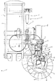
図7はサイドブラシ支持装置31及びサイドブラシ47の概要を示す清掃ロボット1の要部正面図、図8は同要部平面図、図9は図8のA部拡大図、図10は同要部側面図、図11はB部拡大図である。
7 is a front view of the main part of the cleaning
図7乃至図11に示すように、ロボット本体2の下部にフレーム5が配置される。フレーム5は、前後方向に延在する複数の縦フレーム6及び幅方向に延在する複数の横フレーム7によって略格子状に形成し、このフレーム5に駆動輪11a、11b、キャスタ12a、12b、障害物センサ13a〜13c、方位センサ等の走行装置10を搭載乃至支持する。また、清掃部コントローラ21、パワーブラシ23、ダストボックス、及びサイドブラシ支持装置31に支持されたサイドブラシ47等の清掃装置20を搭載乃至支持する。
As shown in FIGS. 7 to 11, the
サイドブラシ支持装置31は、ロボット本体2の前部においてフレーム5の横フレーム7の端部に取り付けられた取付ブラケット8に、幅方向に延在する第1揺動軸32によって基端部を上下方向に揺動自在に支持して前方向に延在する軸状の昇降揺動部材33、昇降揺動部材33に第2揺動軸35を介して幅方向に揺動自在に支持された第1揺動部材36及び該第1揺動部材36に第3揺動軸40を介して幅方向に揺動自在に支持された第2揺動部材41を有する揺動支持部材を備える。
The side
第1揺動軸32によって基端部が上下方向に揺動自在に支持して前方向に延在する軸状の昇降揺動部材33は、下方揺動端規制手段であるストッパボルト34が昇降揺動部材33に当接することによって下方の移動端を調整する。
The shaft-like lifting / lowering swinging
第1揺動部材36は、上端部が第2揺動軸35を介して幅方向に揺動自在に昇降揺動部材33に支持されて下方に延在する基部37と、基部37の下端部に基端が結合されて前方に移行するに従って漸次幅方向外方に移行するように斜め前方に延在する上面部38A、下面部38B、両側面部38Cを備えた矩形断面形状のアーム部38を有する。更に、基部37から幅方向内方に突出する揺動規制ブラケット39aを設け、この揺動規制ブラケット39aの先端にストッパボルト39bを設ける。このストッパボルト39bがフレーム5に設けられた幅方向内方ストッパ39c或いは幅方向外方ストッパ39dに当接して第1揺動部材36の幅方向の揺動端を格納位置或いは使用位置に規制する第1揺動部材揺動端規制手段39を形成する。
The first swinging
第1揺動部材36のアーム部38の先端において突出する上面部38A及び下面部38Bの先端部に上下方向に延在する第3揺動軸40を介して第2揺動部材41を幅方向に揺動自在に支持する。第2揺動部材41は先端部となる取付部41Cの上端及び下端に基端部となる上面部41A及び下面部41Bが第1揺動部材36のアーム部38における上面部38Aの下面及び下面部38Bの上面に沿って延在する断面略コ字状であって、互いに対向する第1揺動部材36及び第2揺動部材41のアーム部38における上面部38Aと41A及び下面部38Bと41Bを第3揺動軸40によって回動自在に連結する。
The second oscillating
更に、第2揺動部材41の上面部41A及び下面部41Bにそれぞれ第3揺動軸40を中心とする円孔状に開口するストッパ溝42Aと、ストッパ溝42A内を移動可能に貫通して両端部がアーム部38の上面部38Aと下面部38Bとの間に掛け渡したストッパ軸42Bによって構成される第2揺動部材揺動端規制手段42を備える。第2揺動部材41が第3揺動軸40を中心に第1揺動部材36のアーム部38に対して幅方向外方に揺動した際にストッパ溝42Aの外方端42Aaがストッパ軸42Bに当接することにより第1揺動部材36のアーム部38に対する第2揺動部材41の外方への揺動端となる使用位置に規制し、第2揺動部材41が第1揺動部材36のアーム部38に対して幅方向内方に揺動した際にストッパ溝42Aの内方端42Abがストッパ軸42Bに当接して第1揺動部材36に対する第2揺動部材41の内方への揺動端となる格納位置に規制する。
Furthermore, a
第2揺動部41の取付部41Cに取り付けるサイドブラシモータカバー45は、矩形の頂面45A、頂面45Aの各周縁から下方に折曲形成された取付面壁45B、取付面壁45Bと対峙する前面壁45C、取付面壁45Bと前面壁45Cの側端間に架設される両側面壁45D、45E等の周壁を備えた下方が開放する箱状であって、取付面壁45Bを第2揺動部41の取付部41Cに取り付ける。
The side
サイドブラシモータカバー45内に回転軸46aがほぼ上下方向に延在するサイドブラシモータ46を保持し、サイドブラシモータ46の回転軸46aの先端にサイドブラシ47を取り付ける。サイドブラシ47は回転軸46aの先端に取り付けられる円板状の基部47A及び基部47Aの下面に円錐台形に植毛された線状のブラシ材47Bを備える。このサイドブラシ47は接地状態で清掃ロボット1の走行方向前方に所定角度で傾斜し、サイドブラシ47の前部が接地するように設ける。このサイドブラシ47はサイドブラシモータ46によって図10及び図11に矢印Rで示すように接地する走行方向前方側が車幅方向外方側から内方側へ移動する方向、即ち、塵埃等を車幅方向外方側から内方側に掃き寄せる方向に回転する。
A
サイドブラシモータカバー45の前面壁45Cの外周から両側面壁45D、45Eの外周を覆う発泡ウレタン等の弾性材によってコ字状に形成されたサイドブラシバンパ48を設ける。このサイドブラシバンパ48はサイドブラシモータカバー45の前面壁45C及び両側面壁45D、45Eの外面を覆うと共に平面視状態において少なくともサイドブラシ47の基部47Aを上方から覆う外形形状を有する。
A
また、サイドブラシモータカバー45とサイドブラシバンパ48との間に、予め設定された外力、即ち衝撃荷重がサイドブラシバンパ48に作用した際にその衝撃を検知する圧電素子等からなる図示しない衝撃検知センサを設ける。この衝撃センサが所定値以上の衝撃を検知した際には走行装置10及び清掃装置20の動作を停止する。
Further, an impact detection (not shown) comprising a piezoelectric element or the like for detecting an impact when a preset external force, that is, an impact load is applied to the
次に、サイドブラシ47を床面Gに接地した使用位置と床面Gから上昇して格納位置に移動せしめるサイドブラシ移動手段50について説明する。
Next, the use position where the
サイドブラシ移動手段50は、フレーム5に搭載されて後述する昇降動作用牽引索となる第1牽引ケーブル52を牽引及び繰り出す昇降用牽引アクチュエータと格納動作用牽引索となる第2牽引ケーブル55を牽引及び繰り出す格納用牽引アクチュエータを兼備する牽引アクチュエータであるシリンダモータ51を有し、シリンダモータ51の軸部51aの伸長及び収縮によって第1牽引ケーブル52及び第2牽引ケーブル55を使用位置と格納位置との間で牽引及び繰り出す。
The side brush moving means 50 pulls a lifting traction actuator that pulls and unwinds a
第1牽引ケーブル52は、可撓性を有し基端がクレビス53aを介してシリンダモータ51の軸部51aに連結し、先端がフレーム5の下部に前後方向に延在して配設されたケーブルガイド53b及びサイドブラシ支持装置31より幅方向内方でかつ上方においてフレーム5に上下方向に延在して配設されたケーブルガイド53cに誘導されて幅方向内方でかつ上方から傾斜して垂下すると共にクレビス53dを介して第1揺動部材36のアーム部38の基端近傍を吊下する。
The
シリンダモータ51により第1牽引ケーブル52を格納位置に牽引した際に第1揺動軸32を中心にサイドブラシ支持装置31が上方に揺動し、昇降揺動部材33がストッパボルト34に当接することによってサイドブラシ支持装置31の上昇揺動が規制されると共に、第2揺動軸35を中心に第1揺動部材36が幅方向内方に揺動して揺動規制ブラケット39aの先端に設けたストッパボルト39bが幅方向ストッパ39cに当接して第1揺動部材36の幅方向内方揺動端となる格納位置に規制する。
When the
一方、シリンダモータ51により第1牽引ケーブル52を使用位置に繰り出した際に、第1牽引ケーブル52によって吊り下げられたサイドブラシ支持装置31が第1揺動軸32を中心に下方に揺動し、かつ昇降揺動部材33がストッパボルト34に当接してサイドブラシ支持装置31の下方揺動端である使用位置に規制される。また、第1牽引ケーブル52を使用位置に繰り出した際にサイドブラシ47が床面Gに接地したときには、昇降揺動部材33がストッパボルト34に当接することなく牽引ケーブル52が若干撓み、サイドブラシ47の接地状態が維持できる。
On the other hand, when the
第2牽引ケーブル55は、可撓性有し基端がクレビス56aを介してシリンダモータ51の軸部51aに連結し、先端がフレーム5の下部に前後方向に延在して設けられたケーブルガイド56b及び第1揺動部材36の基部37に前後方向に延在して設けられたケーブルガイド56cに誘導されて第3揺動軸40より幅方向内方を経由してサイドブラシモータカバー45の取付面壁45Bにおける幅方向内方端近傍にクレビス56dを介して結合する。
The
シリンダモータ51により第2牽引ケーブル55を格納位置に牽引した際にサイドブラシモータカバー45の車幅方向内方端が牽引されて図8及び図9に仮想線で示すように第3揺動軸40を中心にサイドブラシモータカバー45及び第2揺動部材41が、その上面部41A及び下面部41Bに形成されたストッパ溝42Aの内方端42Abがストッパ軸42Bに当接する揺動端まで揺動して格納位置に停止する。
When the
一方、シリンダモータ51により第2牽引ケーブル55を使用位置に繰り出した際に、第2牽引ケーブル55による牽引が解除され、サイドブラシモータカバー45及び第2揺動部材41が、その上面部41A及び下面部41Bに形成されたストッパ溝42Aの外方端42Aa或いは内方端42Abがストッパ軸42Bに当接して揺動端が使用位置と格納位置との範囲で揺動可能にある。
On the other hand, when the
次に、このように構成されたサイドブラシ支持装置31及びサイドブラシ47を備えた清掃ロボット1の作用について説明する。
Next, the operation of the cleaning
清掃ロボット1は、予め設定されたプログラムに従って回転駆動される駆動輪11a、11bによって清掃領域内の所定系路を走行しつつ、回転するパワーブラシ23で床面G上の塵埃を掃き上げると共に、必要に応じてサイドブラシ47によりパワーブラシ23の清掃領域外の塵埃を内側、即ちパワーブラシ23の清掃領域内へ掃き寄せ、これらパワーブラシ23で掃き上げられた塵埃及びサイドブラシ47によって掃き寄せられた塵埃を吸引口24からダストボックス内に吸引する。
The cleaning
サイドブラシ47を必要としないときには、サイドブラシモータ46によるサイドブラシ47の回転駆動を停止した状態で、図4に仮想線で示すロボット本体2の下方の格納位置に保持する。
When the
サイドブラシ47を格納位置に移動する作動は、サイドブラシ移動手段50のシリンダモータ51により第1牽引ケーブル52及び第2牽引ケーブル55を使用位置から格納位置に牽引する。このシリンダモータ51による第1牽引ケーブル52を格納位置へ牽引すると、第1牽引ケーブル52の先端52bが連結されたサイドブラシ支持装置31の第1揺動部材36が第1揺動軸32を中心に上方に揺動して引き上げられると共に第2揺動軸35を中心に揺動して幅方向内方に牽引される。これにより第1揺動軸32を中心にサイドブラシ支持装置31が上方に揺動してサイドブラシ47が接地位置、即ち床面Gから離れ、昇降揺動部材33がストッパボルト34に当接して上昇揺動が規制される。また、第1牽引ケーブル52による幅方向内方への牽引により第2揺動軸35を中心に第1揺動部材36が幅方向内方に揺動して揺動規制ブラケット39aに設けられたストッパボルト39bが幅方向内方ストッパ39cに当接して第1揺動部材36の幅方向内方へ格納位置に規制される。
In the operation of moving the
一方、第2牽引ケーブル55の格納位置への牽引に伴って、第2牽引ケーブル55の先端が連結されたサイドブラシモータカバー45の車幅方向内方端が牽引されて第3揺動軸40を中心に第2揺動部材41が、その上面部41A及び下面部41Bに形成されたストッパ溝42Aの内方端42Abがストッパ軸42Bに当接する揺動端まで揺動して格納位置に停止する。
On the other hand, as the
これによりサイドブラシ支持装置31に保持されたサイドブラシ47は接地位置から離れると共にサイドブラシモータカバー45がほぼロボット本体2の下面に格納される。また、サイドブラシモータカバー45の一部がバンパ3の前部に突出した状態で格納されてもサイドブラシモータカバー45の前面壁45C及び側面壁45D、45Eが弾性部材からなるサイドブラシバンパ48によって被覆されることから、仮に障害物等に接触しても傷害物に損傷を与えることが防止できる。特に人体に接触した際に人体に与えるダメージが抑制されて安全性が確保できる。
As a result, the
一方、サイドブラシ47を使用する床面Gの清掃にあたっては、サイドブラシ移動手段50のシリンダモータ51により第1牽引ケーブル52及び第2牽引ケーブル55を使用位置に繰り出す。この第1牽引ケーブル52の繰り出しに伴って、第1牽引ケーブル52による上方及び幅方向内方への牽引が解除されて第1揺動軸32を中心にサイドブラシ支持装置31、サイドブラシモータ46及びサイドブラシ47等の自重により下方に揺動してサイドブラシ47の前方部分が床面G上に接触すると共に、第1揺動部材36の第2揺動軸35を中心とした揺動が許容される。
On the other hand, when cleaning the floor G using the
一方、第2牽引ケーブル55の伸長に伴って第2牽引ケーブル55によるサイドブラシモータカバー45の牽引が解除されて第2揺動部材41の第3揺動軸40を中心とする揺動が許容される。
On the other hand, with the extension of the
このようにサイドブラシ47の前方部分がサイドブラシ支持装置31及びサイドブラシ47の自重による予め設定された接地荷重で床面Gに接触した状態でサイドブラシ47を回転駆動すると、回転するサイドブラシ47に作用する床面Gからの反力に伴ってサイドブラシモータ46を支持するサイドブラシモータカバー45が幅方向外方に付勢され、サイドブラシモータカバー45に結合された第2揺動部材41が第3揺動軸40を中心として幅方向外方に揺動してその上面部41A及び上面部41Bに形成されたストッパ溝42Aの外方端42Aaがストッパ軸42Bに当接して第1揺動部材36に対する第2揺動部材41の相対揺動が規制される。更なるサイドブラシ47に作用する床面Gからの反力に伴うサイドブラシモータカバー45の幅方向外方への付勢によって第2揺動部材41と第1揺動部材36が一体的に第2揺動軸35を中心として幅方向外方に揺動し、第1揺動部材36に結合されて揺動する揺動規制ブラケット39aに設けられたストッパボルト39bが幅方向外方ストッパ39dに当接して第1揺動部材36の揺動が規制される。
Thus, when the
これにより第1揺動部材36及び第2揺動部材41の幅方向外方への揺動が規制されてサイドブラシ47が通常使用位置に保持される。
As a result, the
この通常使用位置にサイドブラシ47が通常使用位置に予め設定されたプログラムに従って回転駆動される駆動輪11a、11bによって自律走行しつつ、回転するパワーブラシ23で床面G上の塵埃を掃き上げると共に、サイドブラシ47によりパワーブラシ23の清掃領域外の塵埃を内側、即ちパワーブラシ23の清掃領域内に掃き寄せ、これらパワーブラシ23で掃き上げられた塵埃及びサイドブラシ47によって掃き寄せられた塵埃を吸引口24からダストボックス内に吸引する。
While the
また、サイドブラシ47の前方部分がサイドブラシ支持装置31、サイドブラシモータ46及びサイドブラシ47等の自重による接地荷重で床面Gに接触した状態でサイドブラシ47が回転するので、床面Gに塵埃や土砂等が固く付着している場合でも、固く付着している塵埃や土砂等によってサイドブラシ47が押し上げられることがなく、そのように付着している塵埃や土砂も床面から掃き寄せられ、掃き残しがなく良好に清掃できる。
Further, since the
壁際の清掃を行う際には、走行ロボット1が壁際に寄った状態で走行する。そして、サイドブラシ47の回転により壁際にある塵埃がパワーブラシ23の清掃領域内に掃き寄せられる。清掃ロボット1が壁際に寄りすぎてサイドブラシ47或いはサイドブラシバンパ48が壁面や障害物に接触して、サイドブラシ47或いはサイドブラシバンパ48に対して回転するサイドブラシ47に作用する床面から反力による幅方向外方側への付勢力以上の外力が加わると、サイドブラシ47及びサイドブラシバンパ48はサイドブラシモータカバー45や第2揺動部材41と共に第3揺動軸40を中心に清掃ロボット1の幅方向内方に回動する。
When cleaning the wall, the traveling
サイドブラシ47或いはサイドブラシバンパ48に加わる力、即ち外力が、回転するサイドブラシ47に作用する床面から反力による幅方向外方側への付勢力より小さくなると、サイドブラシ47及びサイドブラシバンパ48は、回転するサイドブラシ47に作用する床面Gから反力によってサイドブラシモータカバー45及び第2揺動部材41と共に第3揺動軸40を中心にストッパ溝42Aの外方端42Aaがストッパ軸42Bに当接するまで揺動して通常使用位置に復帰する。
When the force applied to the
即ち、サイドブラシ47或いはサイドブラシバンパ48は、サイドブラシ47或いはサイドブラシバンパ48に幅方向外方から加わる力に対応して、サイドブラシモータカバー45及び第2揺動部材41と共に第3揺動軸40を中心に幅方向に揺動される。
That is, the
従って、サイドブラシ47或いはサイドブラシバンパ48が壁面や障害物に接触しても、サイドブラシ47或いはサイドブラシバンパ48に過剰な力が加わるのが防止され、サイドブラシ47やサイドブラシ47を支持するサイドブラシ支持装置31の破損が確実に回避される。また、サイドブラシ47やサイドブラシバンパ48の接触により発生する壁面や障害物の損傷が防止できる。
Therefore, even if the
その結果、サイドブラシ47及びサイドブラシ支持装置31等の破損を考慮することなく、清掃ロボット1を壁際近傍に寄せた状態で清掃作業を行うことができ、良好な清掃状態を確保できる。
As a result, the cleaning operation can be performed in a state where the cleaning
また、種々の実験の結果、清掃ロボット1の進行方向に対するサイドブラシ47の突出角度、即ち、進行方向に対する揺動中心となる第3揺動軸40とサイドブラシ47の回転中心となるサイドブラシモータ46の回転軸46aとを結ぶ仮想線の延在方向が45°以内においてサイドブラシ47或いはサイドブラシバンパ48に幅方向外方から加わる力に対応して良好に第3揺動軸40を中心に幅方向に揺動することが確認された。
Further, as a result of various experiments, the protruding angle of the
また、シリンダモータ51により第1牽引ケーブル52及び第2牽引ケーブル55の繰り出しによりサイドブラシ47を下降して床面Gと接触させ、サイドブラシ47の回転に伴う床面Gからの反力で第1揺動部材36及び第2揺動部材41を幅方向外方に付勢することから、第1揺動部材36及び第2揺動部材41を幅方向に揺動させるシリンダ機構等のアクチュエータが不要であり、構成及び作動制御の簡素化が得られる。更に第1牽引ケーブル52及び第2牽引ケーブル55は可撓性を有し、引き回しが容易でシリンダモータ51の設置場所の選択が容易でその設置スペースが容易に確保できて設計の自由度が確保できる。
Further, the
なお、本発明は上記実施の形態に限定されることなく、発明の趣旨を逸脱しない範囲で種々変更可能である。例えば、上記実施の形態では第2牽引ケーブルの先端をサイドブラシモータカバー45に連結したが第2揺動部材41に連結することもできる。上記実施の形態では第1牽引ケーブル52及び第2牽引ケーブル55を単一の牽引アクチュエータであるシリンダモータ51によって格納位置に牽引すると共に使用位置に繰り出すことにより構造及び制御の簡素化を図ったが、それぞれ別個の昇降用牽引アクチュエータ及び格納用牽引アクチュエータを使用することもできる。また、サイドブラシ47を清掃ロボット1の左右にそれぞれ配置したが、左右の一方にのみ配置することもできる。また、パワーブラシを省略した清掃ロボットや、洗浄液を散水すると共に清掃ブラシで床面を清掃して汚水を吸引回収する清掃ロボット等種々のタイプのサイドブラシ等に広く適用することができる。
In addition, this invention is not limited to the said embodiment, A various change is possible in the range which does not deviate from the meaning of invention. For example, although the tip of the second traction cable is connected to the side
1 清掃ロボット
2 ロボット本体
10 走行部
20 清掃部
31 サイドブラシ支持装置
32 第1揺動軸
33 昇降揺動部材(揺動部材)
33a 基端部
33b 先端
34 ストッパボルト(下方揺動端規制手段)
35 第2揺動軸
36 第1揺動部材(揺動部材)
39 第1揺動部材揺動端規制手段
40 第3揺動軸
41 第2揺動部材(揺動部材)
42 第2揺動部材揺動端規制手段
45 サイドブラシモータカバー
46 サイドブラシモータ
47 サイドブラシ
48 サイドブラシバンパ
50 サイドブラシ移動手段
51 シリンダモータ(牽引アクチュエータ)
52 第1牽引ケーブル(昇降動作牽引策)
55 第2牽引ケーブル(収納動作牽引策)
DESCRIPTION OF
33a Base
35
39 First swing member swing end regulating means 40
42 Second swing member swing
52 First traction cable (lifting traction measures)
55 Second traction cable (traction action traction measure)
Claims (4)
基端が第1揺動軸を介して上下方向に揺動自在にロボット本体の下面に支持されて前方に延出する昇降揺動部材と、
該昇降揺動部材に基部が第2揺動軸を介して幅方向に揺動自在に連結されて前方に延出する第1揺動部材と、
上記昇降揺動部材に対する第1揺動部材の幅方向外方及び内方の揺動端をそれぞれ使用位置と格納位置とに規制する第1揺動部材揺動端規制手段と、
上記第1揺動部材の先端に基端部が第3揺動軸を介して幅方向に揺動自在に連結されて前方に延在する先端部にサイドブラシモータによって回転駆動されるサイドブラシを保持するサイドブラシモータカバーを支持する第2揺動部材と、
上記第1揺動部材に対する第2揺動部材の幅方向外方及び内方の揺動端をそれぞれ使用位置と格納位置に規制する第2揺動部材揺動端規制手段と、
上記第1揺動部材を上方から吊り下げる昇降動作牽引索及び該昇降動作牽引索を繰り出して上記第1揺動部材が下降した使用位置と牽引して上昇した格納位置との間で昇降揺動させる昇降用牽引アクチュエータと、
上記サイドブラシモータカバーに先端が連結される格納動作牽引索及び該格納動作牽引索を使用位置に繰り出して上記第2揺動部材の揺動を許容する一方格納位置に牽引してサイドブラシモータカバーを格納位置に保持する格納用牽引アクチュエータと、を備え、
上記格納用牽引アクチュエータによる格納動作牽引索の使用位置への繰り出しにより上記第2揺動部材の揺動許容をして上記昇降用牽引アクチュエータによる昇降動作牽引索の使用位置への繰り出しによる上記第1揺動部材の使用位置において床面に接触するサイドブラシの回転に伴う床面からの反力により上記第1揺動部材及び第2揺動部材を幅方向外方に付勢する一方、昇降用牽引アクチュエータによる昇降動作牽引索の格納位置への牽引及び格納用牽引アクチュエータによる格納動作牽引索の格納位置への牽引でサイドブラシが床面から上昇した状態でロボット本体の下方に収納されることを特徴とする清掃ロボットのサイドブラシ支持装置。 It is supported on the lower surface of the robot body provided with a traveling unit via a side brush support device so as to protrude outward in the width direction and forward from the robot body, and is rotated to remove dust on the floor surface of the robot body. In a side brush support device of a cleaning robot provided with a cleaning unit having a side brush that sweeps inward in the width direction,
An elevating swinging member whose base end is supported by the lower surface of the robot body so as to be swingable in the vertical direction via the first swinging shaft and extends forward;
A first oscillating member whose base is connected to the ascending / descending oscillating member so as to be able to oscillate in the width direction via a second oscillating shaft, and extends forward;
First rocking member rocking end regulating means for regulating the widthwise outer and inner rocking ends of the first rocking member with respect to the lifting rocking member to a use position and a storage position, respectively.
A side brush which is driven to rotate by a side brush motor is attached to a distal end portion of which the base end portion is connected to the distal end of the first swinging member so as to be swingable in the width direction via a third swinging shaft. A second swing member that supports the side brush motor cover to be held;
A second rocking member rocking end restricting means for restricting the widthwise outer and inner rocking ends of the second rocking member relative to the first rocking member to a use position and a storage position, respectively;
Elevating / lowering towing line for suspending the first oscillating member from above and raising / lowering oscillating between the use position in which the first oscillating member is lowered by pulling out the elevating / retracting towing line and the retracted position to which the first oscillating member is pulled up A lifting traction actuator
A retracting operation retracting line having a tip connected to the side brush motor cover, and retracting the retracting operation retracting line to a use position to allow the second swinging member to swing, while pulling to the retracted position and the side brush motor cover A retractable traction actuator for holding the
The second swing member is allowed to swing when the retracting traction actuator is extended to the use position, and the first traction actuator is extended to the use position by the elevating traction actuator. The first swing member and the second swing member are urged outward in the width direction by the reaction force from the floor surface due to the rotation of the side brush that contacts the floor surface at the use position of the swing member, while for lifting and lowering. Lifting and lowering operation by the traction actuator Pulling the retracting rope to the retracted position and retracting operation by the retracting traction actuator Pulling the retracting rope to the retracted position means that the side brush is stored below the robot body while being lifted from the floor surface. A side brush support device for a cleaning robot.
Priority Applications (1)
| Application Number | Priority Date | Filing Date | Title |
|---|---|---|---|
| JP2008201275A JP5243879B2 (en) | 2008-08-04 | 2008-08-04 | Side brush support device for cleaning robot |
Applications Claiming Priority (1)
| Application Number | Priority Date | Filing Date | Title |
|---|---|---|---|
| JP2008201275A JP5243879B2 (en) | 2008-08-04 | 2008-08-04 | Side brush support device for cleaning robot |
Publications (2)
| Publication Number | Publication Date |
|---|---|
| JP2010035773A JP2010035773A (en) | 2010-02-18 |
| JP5243879B2 true JP5243879B2 (en) | 2013-07-24 |
Family
ID=42008921
Family Applications (1)
| Application Number | Title | Priority Date | Filing Date |
|---|---|---|---|
| JP2008201275A Active JP5243879B2 (en) | 2008-08-04 | 2008-08-04 | Side brush support device for cleaning robot |
Country Status (1)
| Country | Link |
|---|---|
| JP (1) | JP5243879B2 (en) |
Cited By (2)
| Publication number | Priority date | Publication date | Assignee | Title |
|---|---|---|---|---|
| KR101907161B1 (en) * | 2011-10-06 | 2018-10-15 | 삼성전자주식회사 | Robot cleaner |
| WO2021107320A1 (en) * | 2019-11-29 | 2021-06-03 | Lg Electronics Inc. | Robot cleaner |
Families Citing this family (24)
| Publication number | Priority date | Publication date | Assignee | Title |
|---|---|---|---|---|
| DE102009014560A1 (en) * | 2009-03-16 | 2010-09-23 | Alfred Kärcher Gmbh & Co. Kg | Replaceable sweeping brush and sweeper with such sweeping brush device |
| KR101322589B1 (en) * | 2011-09-23 | 2013-11-29 | 엘지전자 주식회사 | Automatic cleaner |
| AU2012310377B2 (en) * | 2011-09-23 | 2015-08-20 | Lg Electronics Inc. | Automatic vacuum cleaner |
| KR101857295B1 (en) * | 2011-12-16 | 2018-05-14 | 엘지전자 주식회사 | Mobile robot cleaner |
| JP2014046207A (en) * | 2012-08-30 | 2014-03-17 | Samsung Electronics Co Ltd | Side brush assembly, robot cleaner and control method for the same |
| KR101469333B1 (en) * | 2012-12-26 | 2014-12-04 | 엘지전자 주식회사 | Automatic cleaner |
| TW201427631A (en) * | 2013-01-08 | 2014-07-16 | Uni Ring Tech Co Ltd | Self-propelled cleaning device |
| WO2014169944A1 (en) * | 2013-04-15 | 2014-10-23 | Aktiebolaget Electrolux | Robotic vacuum cleaner with protruding sidebrush |
| KR101494804B1 (en) * | 2013-04-19 | 2015-02-23 | 주식회사 유진로봇 | Suction Type Cleaning Robot |
| CN104146649B (en) * | 2013-05-13 | 2017-05-10 | 科沃斯机器人股份有限公司 | Self-moving adsorption robot |
| KR101306483B1 (en) | 2013-06-18 | 2013-09-09 | 엘지전자 주식회사 | Automatic cleaner |
| WO2014208192A1 (en) * | 2013-06-27 | 2014-12-31 | シンフォニアテクノロジー株式会社 | Cleaning device |
| TWI601508B (en) * | 2014-01-03 | 2017-10-11 | cheng-xiang Yan | Automatic cleaning machine |
| US10130231B2 (en) | 2015-07-31 | 2018-11-20 | Diversey, Inc. | Floor cleaning apparatus and method of cleaning a floor |
| CN109480712A (en) * | 2018-12-22 | 2019-03-19 | 深圳市银星智能科技股份有限公司 | Clean robot |
| CN109997704B (en) * | 2019-05-13 | 2023-10-20 | 哈尔滨天河自动化设备有限公司 | Clear excrement robot in pig house |
| JP2021087556A (en) * | 2019-12-03 | 2021-06-10 | オムロン株式会社 | Autonomous travel type cleaning device |
| CN111528736B (en) * | 2020-05-07 | 2021-09-24 | 苏州高之仙自动化科技有限公司 | Side brush installation mechanism, side brush device and cleaning robot |
| CN113964662B (en) * | 2021-09-18 | 2024-03-12 | 天津市威匡电气设备有限公司 | Novel weak current switch board device |
| CN113774840B (en) * | 2021-09-28 | 2023-04-11 | 上海高仙自动化科技发展有限公司 | Side brush structure and floor cleaning equipment with same |
| CN114224230B (en) * | 2021-12-14 | 2023-02-07 | 广东盈峰智能环卫科技有限公司 | Dust pushing mechanism and floor sweeping robot |
| CN114808813B (en) * | 2022-04-15 | 2024-03-22 | 苏州高之仙自动化科技有限公司 | Side brush device and cleaning robot with same |
| KR20230155898A (en) * | 2022-05-04 | 2023-11-13 | 삼성전자주식회사 | Driving Robot apparatus, controlling method thereof, and recording medium for recording program |
| CN114767015A (en) * | 2022-05-13 | 2022-07-22 | 麦岩智能科技(北京)有限公司 | Variable width lift drags head |
Family Cites Families (5)
| Publication number | Priority date | Publication date | Assignee | Title |
|---|---|---|---|---|
| ES2064165T3 (en) * | 1991-02-01 | 1995-01-16 | Kurt Zachhuber | SOIL HANDLING MACHINE. |
| JPH05228090A (en) * | 1992-02-20 | 1993-09-07 | Matsushita Electric Ind Co Ltd | Self-traveling type cleaner |
| JP3134485B2 (en) * | 1992-04-27 | 2001-02-13 | 株式会社豊田自動織機製作所 | Side brush support structure for floor cleaning vehicles |
| DE4340367C2 (en) * | 1993-11-26 | 2003-12-11 | Vorwerk Co Interholding | Floor care device |
| JP4243594B2 (en) * | 2005-01-31 | 2009-03-25 | パナソニック電工株式会社 | Cleaning robot |
-
2008
- 2008-08-04 JP JP2008201275A patent/JP5243879B2/en active Active
Cited By (5)
| Publication number | Priority date | Publication date | Assignee | Title |
|---|---|---|---|---|
| KR101907161B1 (en) * | 2011-10-06 | 2018-10-15 | 삼성전자주식회사 | Robot cleaner |
| WO2021107320A1 (en) * | 2019-11-29 | 2021-06-03 | Lg Electronics Inc. | Robot cleaner |
| KR20210067275A (en) * | 2019-11-29 | 2021-06-08 | 엘지전자 주식회사 | Robot Cleaner |
| KR102262726B1 (en) * | 2019-11-29 | 2021-06-09 | 엘지전자 주식회사 | Robot Cleaner |
| US11583155B2 (en) | 2019-11-29 | 2023-02-21 | Lg Electronics Inc. | Robot cleaner |
Also Published As
| Publication number | Publication date |
|---|---|
| JP2010035773A (en) | 2010-02-18 |
Similar Documents
| Publication | Publication Date | Title |
|---|---|---|
| JP5243879B2 (en) | Side brush support device for cleaning robot | |
| JP5512225B2 (en) | Self-propelled cleaning robot with side brush device | |
| KR101311295B1 (en) | Wheel assembly for moving robot | |
| KR101361562B1 (en) | Cleanning robot | |
| KR102280210B1 (en) | Robot cleaner and control method thereof | |
| TWI596458B (en) | Self-propelled electronic device and the above-mentioned self-propelled electronic device walking method | |
| KR20160121844A (en) | Driving unit and robot cleaner having the same | |
| ITFI20010021A1 (en) | AUTOMATIC VACUUM CLEANING APPARATUS FOR FLOORS | |
| JP2005177459A (en) | Robot cleaner and operating method thereof | |
| JPH03191939A (en) | Floor washer | |
| KR20200007490A (en) | Device for adjusting the height of the driving wheel for robot cleaner | |
| JP3345982B2 (en) | Mobile work robot | |
| JP3738459B2 (en) | Self-propelled vacuum cleaner | |
| JP3486923B2 (en) | Vacuum cleaner | |
| KR100596482B1 (en) | Climbing Structure for Mobile Robot with Suction Assembly | |
| JP2008074178A (en) | Washing method of car washing machine | |
| CN110254548A (en) | A kind of climbing robot | |
| JP2015110410A (en) | Self-traveling type washing machine | |
| KR200454118Y1 (en) | A safety winch equipment for high place works | |
| JP2008254472A (en) | Track/road vehicle | |
| JP6874489B2 (en) | Self-propelled futon vacuum cleaner | |
| KR100862334B1 (en) | Apparatus for gondola | |
| KR20100132147A (en) | Mobile body and method for controlling traveling of the same | |
| JP3314468B2 (en) | Mobile work robot | |
| JP4354440B2 (en) | Crawler work vehicle |
Legal Events
| Date | Code | Title | Description |
|---|---|---|---|
| A621 | Written request for application examination |
Free format text: JAPANESE INTERMEDIATE CODE: A621 Effective date: 20110603 |
|
| A977 | Report on retrieval |
Free format text: JAPANESE INTERMEDIATE CODE: A971007 Effective date: 20121017 |
|
| A131 | Notification of reasons for refusal |
Free format text: JAPANESE INTERMEDIATE CODE: A131 Effective date: 20121023 |
|
| A521 | Written amendment |
Free format text: JAPANESE INTERMEDIATE CODE: A523 Effective date: 20121213 |
|
| TRDD | Decision of grant or rejection written | ||
| A01 | Written decision to grant a patent or to grant a registration (utility model) |
Free format text: JAPANESE INTERMEDIATE CODE: A01 Effective date: 20130319 |
|
| A61 | First payment of annual fees (during grant procedure) |
Free format text: JAPANESE INTERMEDIATE CODE: A61 Effective date: 20130405 |
|
| FPAY | Renewal fee payment (event date is renewal date of database) |
Free format text: PAYMENT UNTIL: 20160412 Year of fee payment: 3 |
|
| R150 | Certificate of patent or registration of utility model |
Free format text: JAPANESE INTERMEDIATE CODE: R150 Ref document number: 5243879 Country of ref document: JP Free format text: JAPANESE INTERMEDIATE CODE: R150 |
|
| S111 | Request for change of ownership or part of ownership |
Free format text: JAPANESE INTERMEDIATE CODE: R313113 |
|
| R350 | Written notification of registration of transfer |
Free format text: JAPANESE INTERMEDIATE CODE: R350 |
|
| R250 | Receipt of annual fees |
Free format text: JAPANESE INTERMEDIATE CODE: R250 |
|
| R250 | Receipt of annual fees |
Free format text: JAPANESE INTERMEDIATE CODE: R250 |
|
| R250 | Receipt of annual fees |
Free format text: JAPANESE INTERMEDIATE CODE: R250 |
|
| R250 | Receipt of annual fees |
Free format text: JAPANESE INTERMEDIATE CODE: R250 |
|
| R250 | Receipt of annual fees |
Free format text: JAPANESE INTERMEDIATE CODE: R250 |