JP5240749B2 - Thin film transistor substrate, method for manufacturing the same, and liquid crystal display device including the same - Google Patents
Thin film transistor substrate, method for manufacturing the same, and liquid crystal display device including the same Download PDFInfo
- Publication number
- JP5240749B2 JP5240749B2 JP2007103001A JP2007103001A JP5240749B2 JP 5240749 B2 JP5240749 B2 JP 5240749B2 JP 2007103001 A JP2007103001 A JP 2007103001A JP 2007103001 A JP2007103001 A JP 2007103001A JP 5240749 B2 JP5240749 B2 JP 5240749B2
- Authority
- JP
- Japan
- Prior art keywords
- region
- pixel
- substrate
- electrode
- reflective
- Prior art date
- Legal status (The legal status is an assumption and is not a legal conclusion. Google has not performed a legal analysis and makes no representation as to the accuracy of the status listed.)
- Active
Links
- 239000000758 substrate Substances 0.000 title claims description 87
- 239000004973 liquid crystal related substance Substances 0.000 title claims description 51
- 239000010409 thin film Substances 0.000 title claims description 48
- 238000000034 method Methods 0.000 title description 34
- 238000004519 manufacturing process Methods 0.000 title description 17
- 239000010410 layer Substances 0.000 claims description 75
- 230000005540 biological transmission Effects 0.000 claims description 13
- 239000011159 matrix material Substances 0.000 claims description 12
- 239000003990 capacitor Substances 0.000 claims description 10
- 238000003860 storage Methods 0.000 claims description 10
- 239000010408 film Substances 0.000 description 76
- 230000001681 protective effect Effects 0.000 description 26
- 239000004065 semiconductor Substances 0.000 description 10
- 238000000059 patterning Methods 0.000 description 9
- 238000005530 etching Methods 0.000 description 7
- 229910021420 polycrystalline silicon Inorganic materials 0.000 description 7
- 229920005591 polysilicon Polymers 0.000 description 7
- 239000012535 impurity Substances 0.000 description 6
- 229910052751 metal Inorganic materials 0.000 description 6
- 239000002184 metal Substances 0.000 description 6
- 229910052581 Si3N4 Inorganic materials 0.000 description 5
- VYPSYNLAJGMNEJ-UHFFFAOYSA-N Silicium dioxide Chemical compound O=[Si]=O VYPSYNLAJGMNEJ-UHFFFAOYSA-N 0.000 description 5
- HQVNEWCFYHHQES-UHFFFAOYSA-N silicon nitride Chemical compound N12[Si]34N5[Si]62N3[Si]51N64 HQVNEWCFYHHQES-UHFFFAOYSA-N 0.000 description 5
- 229910052814 silicon oxide Inorganic materials 0.000 description 5
- 239000000126 substance Substances 0.000 description 5
- 239000011651 chromium Substances 0.000 description 4
- 239000004020 conductor Substances 0.000 description 4
- 239000010936 titanium Substances 0.000 description 4
- BQCADISMDOOEFD-UHFFFAOYSA-N Silver Chemical compound [Ag] BQCADISMDOOEFD-UHFFFAOYSA-N 0.000 description 3
- 229910052782 aluminium Inorganic materials 0.000 description 3
- XAGFODPZIPBFFR-UHFFFAOYSA-N aluminium Chemical group [Al] XAGFODPZIPBFFR-UHFFFAOYSA-N 0.000 description 3
- 230000005684 electric field Effects 0.000 description 3
- 150000002500 ions Chemical class 0.000 description 3
- 229910052709 silver Inorganic materials 0.000 description 3
- 239000004332 silver Substances 0.000 description 3
- VYZAMTAEIAYCRO-UHFFFAOYSA-N Chromium Chemical compound [Cr] VYZAMTAEIAYCRO-UHFFFAOYSA-N 0.000 description 2
- ZOKXTWBITQBERF-UHFFFAOYSA-N Molybdenum Chemical compound [Mo] ZOKXTWBITQBERF-UHFFFAOYSA-N 0.000 description 2
- 229910052779 Neodymium Inorganic materials 0.000 description 2
- RTAQQCXQSZGOHL-UHFFFAOYSA-N Titanium Chemical compound [Ti] RTAQQCXQSZGOHL-UHFFFAOYSA-N 0.000 description 2
- 229910021417 amorphous silicon Inorganic materials 0.000 description 2
- 229910052804 chromium Inorganic materials 0.000 description 2
- 239000010949 copper Substances 0.000 description 2
- 238000002425 crystallisation Methods 0.000 description 2
- 230000008025 crystallization Effects 0.000 description 2
- 239000010931 gold Substances 0.000 description 2
- 239000000463 material Substances 0.000 description 2
- 239000012528 membrane Substances 0.000 description 2
- 229910052750 molybdenum Inorganic materials 0.000 description 2
- 239000011733 molybdenum Substances 0.000 description 2
- QEFYFXOXNSNQGX-UHFFFAOYSA-N neodymium atom Chemical compound [Nd] QEFYFXOXNSNQGX-UHFFFAOYSA-N 0.000 description 2
- 238000000206 photolithography Methods 0.000 description 2
- 238000000926 separation method Methods 0.000 description 2
- 239000002356 single layer Substances 0.000 description 2
- 229910052715 tantalum Inorganic materials 0.000 description 2
- GUVRBAGPIYLISA-UHFFFAOYSA-N tantalum atom Chemical compound [Ta] GUVRBAGPIYLISA-UHFFFAOYSA-N 0.000 description 2
- 229910052719 titanium Inorganic materials 0.000 description 2
- RYGMFSIKBFXOCR-UHFFFAOYSA-N Copper Chemical compound [Cu] RYGMFSIKBFXOCR-UHFFFAOYSA-N 0.000 description 1
- 239000004593 Epoxy Substances 0.000 description 1
- XUIMIQQOPSSXEZ-UHFFFAOYSA-N Silicon Chemical compound [Si] XUIMIQQOPSSXEZ-UHFFFAOYSA-N 0.000 description 1
- NIXOWILDQLNWCW-UHFFFAOYSA-N acrylic acid group Chemical group C(C=C)(=O)O NIXOWILDQLNWCW-UHFFFAOYSA-N 0.000 description 1
- 229910045601 alloy Inorganic materials 0.000 description 1
- 239000000956 alloy Substances 0.000 description 1
- 238000005452 bending Methods 0.000 description 1
- 229910052802 copper Inorganic materials 0.000 description 1
- 238000007715 excimer laser crystallization Methods 0.000 description 1
- PCHJSUWPFVWCPO-UHFFFAOYSA-N gold Chemical compound [Au] PCHJSUWPFVWCPO-UHFFFAOYSA-N 0.000 description 1
- 229910052737 gold Inorganic materials 0.000 description 1
- AMGQUBHHOARCQH-UHFFFAOYSA-N indium;oxotin Chemical compound [In].[Sn]=O AMGQUBHHOARCQH-UHFFFAOYSA-N 0.000 description 1
- 239000012212 insulator Substances 0.000 description 1
- 238000005468 ion implantation Methods 0.000 description 1
- 238000005499 laser crystallization Methods 0.000 description 1
- 230000003287 optical effect Effects 0.000 description 1
- 238000001579 optical reflectometry Methods 0.000 description 1
- 239000011368 organic material Substances 0.000 description 1
- 238000007789 sealing Methods 0.000 description 1
- 229910052710 silicon Inorganic materials 0.000 description 1
- 239000010703 silicon Substances 0.000 description 1
- 239000007790 solid phase Substances 0.000 description 1
- 125000006850 spacer group Chemical group 0.000 description 1
- 238000002834 transmittance Methods 0.000 description 1
- YVTHLONGBIQYBO-UHFFFAOYSA-N zinc indium(3+) oxygen(2-) Chemical compound [O--].[Zn++].[In+3] YVTHLONGBIQYBO-UHFFFAOYSA-N 0.000 description 1
Images


Classifications
-
- G—PHYSICS
- G02—OPTICS
- G02F—OPTICAL DEVICES OR ARRANGEMENTS FOR THE CONTROL OF LIGHT BY MODIFICATION OF THE OPTICAL PROPERTIES OF THE MEDIA OF THE ELEMENTS INVOLVED THEREIN; NON-LINEAR OPTICS; FREQUENCY-CHANGING OF LIGHT; OPTICAL LOGIC ELEMENTS; OPTICAL ANALOGUE/DIGITAL CONVERTERS
- G02F1/00—Devices or arrangements for the control of the intensity, colour, phase, polarisation or direction of light arriving from an independent light source, e.g. switching, gating or modulating; Non-linear optics
- G02F1/01—Devices or arrangements for the control of the intensity, colour, phase, polarisation or direction of light arriving from an independent light source, e.g. switching, gating or modulating; Non-linear optics for the control of the intensity, phase, polarisation or colour
- G02F1/13—Devices or arrangements for the control of the intensity, colour, phase, polarisation or direction of light arriving from an independent light source, e.g. switching, gating or modulating; Non-linear optics for the control of the intensity, phase, polarisation or colour based on liquid crystals, e.g. single liquid crystal display cells
- G02F1/133—Constructional arrangements; Operation of liquid crystal cells; Circuit arrangements
- G02F1/1333—Constructional arrangements; Manufacturing methods
- G02F1/1343—Electrodes
- G02F1/134309—Electrodes characterised by their geometrical arrangement
-
- G—PHYSICS
- G02—OPTICS
- G02F—OPTICAL DEVICES OR ARRANGEMENTS FOR THE CONTROL OF LIGHT BY MODIFICATION OF THE OPTICAL PROPERTIES OF THE MEDIA OF THE ELEMENTS INVOLVED THEREIN; NON-LINEAR OPTICS; FREQUENCY-CHANGING OF LIGHT; OPTICAL LOGIC ELEMENTS; OPTICAL ANALOGUE/DIGITAL CONVERTERS
- G02F1/00—Devices or arrangements for the control of the intensity, colour, phase, polarisation or direction of light arriving from an independent light source, e.g. switching, gating or modulating; Non-linear optics
- G02F1/01—Devices or arrangements for the control of the intensity, colour, phase, polarisation or direction of light arriving from an independent light source, e.g. switching, gating or modulating; Non-linear optics for the control of the intensity, phase, polarisation or colour
- G02F1/13—Devices or arrangements for the control of the intensity, colour, phase, polarisation or direction of light arriving from an independent light source, e.g. switching, gating or modulating; Non-linear optics for the control of the intensity, phase, polarisation or colour based on liquid crystals, e.g. single liquid crystal display cells
- G02F1/133—Constructional arrangements; Operation of liquid crystal cells; Circuit arrangements
- G02F1/1333—Constructional arrangements; Manufacturing methods
- G02F1/1343—Electrodes
-
- G—PHYSICS
- G02—OPTICS
- G02F—OPTICAL DEVICES OR ARRANGEMENTS FOR THE CONTROL OF LIGHT BY MODIFICATION OF THE OPTICAL PROPERTIES OF THE MEDIA OF THE ELEMENTS INVOLVED THEREIN; NON-LINEAR OPTICS; FREQUENCY-CHANGING OF LIGHT; OPTICAL LOGIC ELEMENTS; OPTICAL ANALOGUE/DIGITAL CONVERTERS
- G02F1/00—Devices or arrangements for the control of the intensity, colour, phase, polarisation or direction of light arriving from an independent light source, e.g. switching, gating or modulating; Non-linear optics
- G02F1/01—Devices or arrangements for the control of the intensity, colour, phase, polarisation or direction of light arriving from an independent light source, e.g. switching, gating or modulating; Non-linear optics for the control of the intensity, phase, polarisation or colour
- G02F1/13—Devices or arrangements for the control of the intensity, colour, phase, polarisation or direction of light arriving from an independent light source, e.g. switching, gating or modulating; Non-linear optics for the control of the intensity, phase, polarisation or colour based on liquid crystals, e.g. single liquid crystal display cells
- G02F1/133—Constructional arrangements; Operation of liquid crystal cells; Circuit arrangements
- G02F1/136—Liquid crystal cells structurally associated with a semi-conducting layer or substrate, e.g. cells forming part of an integrated circuit
-
- G—PHYSICS
- G02—OPTICS
- G02F—OPTICAL DEVICES OR ARRANGEMENTS FOR THE CONTROL OF LIGHT BY MODIFICATION OF THE OPTICAL PROPERTIES OF THE MEDIA OF THE ELEMENTS INVOLVED THEREIN; NON-LINEAR OPTICS; FREQUENCY-CHANGING OF LIGHT; OPTICAL LOGIC ELEMENTS; OPTICAL ANALOGUE/DIGITAL CONVERTERS
- G02F1/00—Devices or arrangements for the control of the intensity, colour, phase, polarisation or direction of light arriving from an independent light source, e.g. switching, gating or modulating; Non-linear optics
- G02F1/01—Devices or arrangements for the control of the intensity, colour, phase, polarisation or direction of light arriving from an independent light source, e.g. switching, gating or modulating; Non-linear optics for the control of the intensity, phase, polarisation or colour
- G02F1/13—Devices or arrangements for the control of the intensity, colour, phase, polarisation or direction of light arriving from an independent light source, e.g. switching, gating or modulating; Non-linear optics for the control of the intensity, phase, polarisation or colour based on liquid crystals, e.g. single liquid crystal display cells
- G02F1/133—Constructional arrangements; Operation of liquid crystal cells; Circuit arrangements
- G02F1/1333—Constructional arrangements; Manufacturing methods
- G02F1/1335—Structural association of cells with optical devices, e.g. polarisers or reflectors
- G02F1/133553—Reflecting elements
- G02F1/133555—Transflectors
-
- G—PHYSICS
- G02—OPTICS
- G02F—OPTICAL DEVICES OR ARRANGEMENTS FOR THE CONTROL OF LIGHT BY MODIFICATION OF THE OPTICAL PROPERTIES OF THE MEDIA OF THE ELEMENTS INVOLVED THEREIN; NON-LINEAR OPTICS; FREQUENCY-CHANGING OF LIGHT; OPTICAL LOGIC ELEMENTS; OPTICAL ANALOGUE/DIGITAL CONVERTERS
- G02F1/00—Devices or arrangements for the control of the intensity, colour, phase, polarisation or direction of light arriving from an independent light source, e.g. switching, gating or modulating; Non-linear optics
- G02F1/01—Devices or arrangements for the control of the intensity, colour, phase, polarisation or direction of light arriving from an independent light source, e.g. switching, gating or modulating; Non-linear optics for the control of the intensity, phase, polarisation or colour
- G02F1/13—Devices or arrangements for the control of the intensity, colour, phase, polarisation or direction of light arriving from an independent light source, e.g. switching, gating or modulating; Non-linear optics for the control of the intensity, phase, polarisation or colour based on liquid crystals, e.g. single liquid crystal display cells
- G02F1/133—Constructional arrangements; Operation of liquid crystal cells; Circuit arrangements
- G02F1/1333—Constructional arrangements; Manufacturing methods
- G02F1/1343—Electrodes
- G02F1/134309—Electrodes characterised by their geometrical arrangement
- G02F1/134345—Subdivided pixels, e.g. for grey scale or redundancy
-
- G—PHYSICS
- G02—OPTICS
- G02F—OPTICAL DEVICES OR ARRANGEMENTS FOR THE CONTROL OF LIGHT BY MODIFICATION OF THE OPTICAL PROPERTIES OF THE MEDIA OF THE ELEMENTS INVOLVED THEREIN; NON-LINEAR OPTICS; FREQUENCY-CHANGING OF LIGHT; OPTICAL LOGIC ELEMENTS; OPTICAL ANALOGUE/DIGITAL CONVERTERS
- G02F1/00—Devices or arrangements for the control of the intensity, colour, phase, polarisation or direction of light arriving from an independent light source, e.g. switching, gating or modulating; Non-linear optics
- G02F1/01—Devices or arrangements for the control of the intensity, colour, phase, polarisation or direction of light arriving from an independent light source, e.g. switching, gating or modulating; Non-linear optics for the control of the intensity, phase, polarisation or colour
- G02F1/13—Devices or arrangements for the control of the intensity, colour, phase, polarisation or direction of light arriving from an independent light source, e.g. switching, gating or modulating; Non-linear optics for the control of the intensity, phase, polarisation or colour based on liquid crystals, e.g. single liquid crystal display cells
- G02F1/133—Constructional arrangements; Operation of liquid crystal cells; Circuit arrangements
- G02F1/136—Liquid crystal cells structurally associated with a semi-conducting layer or substrate, e.g. cells forming part of an integrated circuit
- G02F1/1362—Active matrix addressed cells
- G02F1/136213—Storage capacitors associated with the pixel electrode
-
- G—PHYSICS
- G02—OPTICS
- G02F—OPTICAL DEVICES OR ARRANGEMENTS FOR THE CONTROL OF LIGHT BY MODIFICATION OF THE OPTICAL PROPERTIES OF THE MEDIA OF THE ELEMENTS INVOLVED THEREIN; NON-LINEAR OPTICS; FREQUENCY-CHANGING OF LIGHT; OPTICAL LOGIC ELEMENTS; OPTICAL ANALOGUE/DIGITAL CONVERTERS
- G02F1/00—Devices or arrangements for the control of the intensity, colour, phase, polarisation or direction of light arriving from an independent light source, e.g. switching, gating or modulating; Non-linear optics
- G02F1/01—Devices or arrangements for the control of the intensity, colour, phase, polarisation or direction of light arriving from an independent light source, e.g. switching, gating or modulating; Non-linear optics for the control of the intensity, phase, polarisation or colour
- G02F1/13—Devices or arrangements for the control of the intensity, colour, phase, polarisation or direction of light arriving from an independent light source, e.g. switching, gating or modulating; Non-linear optics for the control of the intensity, phase, polarisation or colour based on liquid crystals, e.g. single liquid crystal display cells
- G02F1/137—Devices or arrangements for the control of the intensity, colour, phase, polarisation or direction of light arriving from an independent light source, e.g. switching, gating or modulating; Non-linear optics for the control of the intensity, phase, polarisation or colour based on liquid crystals, e.g. single liquid crystal display cells characterised by the electro-optical or magneto-optical effect, e.g. field-induced phase transition, orientation effect, guest-host interaction or dynamic scattering
- G02F1/139—Devices or arrangements for the control of the intensity, colour, phase, polarisation or direction of light arriving from an independent light source, e.g. switching, gating or modulating; Non-linear optics for the control of the intensity, phase, polarisation or colour based on liquid crystals, e.g. single liquid crystal display cells characterised by the electro-optical or magneto-optical effect, e.g. field-induced phase transition, orientation effect, guest-host interaction or dynamic scattering based on orientation effects in which the liquid crystal remains transparent
- G02F1/1393—Devices or arrangements for the control of the intensity, colour, phase, polarisation or direction of light arriving from an independent light source, e.g. switching, gating or modulating; Non-linear optics for the control of the intensity, phase, polarisation or colour based on liquid crystals, e.g. single liquid crystal display cells characterised by the electro-optical or magneto-optical effect, e.g. field-induced phase transition, orientation effect, guest-host interaction or dynamic scattering based on orientation effects in which the liquid crystal remains transparent the birefringence of the liquid crystal being electrically controlled, e.g. ECB-, DAP-, HAN-, PI-LC cells
-
- H—ELECTRICITY
- H01—ELECTRIC ELEMENTS
- H01L—SEMICONDUCTOR DEVICES NOT COVERED BY CLASS H10
- H01L27/00—Devices consisting of a plurality of semiconductor or other solid-state components formed in or on a common substrate
- H01L27/02—Devices consisting of a plurality of semiconductor or other solid-state components formed in or on a common substrate including semiconductor components specially adapted for rectifying, oscillating, amplifying or switching and having at least one potential-jump barrier or surface barrier; including integrated passive circuit elements with at least one potential-jump barrier or surface barrier
- H01L27/12—Devices consisting of a plurality of semiconductor or other solid-state components formed in or on a common substrate including semiconductor components specially adapted for rectifying, oscillating, amplifying or switching and having at least one potential-jump barrier or surface barrier; including integrated passive circuit elements with at least one potential-jump barrier or surface barrier the substrate being other than a semiconductor body, e.g. an insulating body
- H01L27/1214—Devices consisting of a plurality of semiconductor or other solid-state components formed in or on a common substrate including semiconductor components specially adapted for rectifying, oscillating, amplifying or switching and having at least one potential-jump barrier or surface barrier; including integrated passive circuit elements with at least one potential-jump barrier or surface barrier the substrate being other than a semiconductor body, e.g. an insulating body comprising a plurality of TFTs formed on a non-semiconducting substrate, e.g. driving circuits for AMLCDs
- H01L27/124—Devices consisting of a plurality of semiconductor or other solid-state components formed in or on a common substrate including semiconductor components specially adapted for rectifying, oscillating, amplifying or switching and having at least one potential-jump barrier or surface barrier; including integrated passive circuit elements with at least one potential-jump barrier or surface barrier the substrate being other than a semiconductor body, e.g. an insulating body comprising a plurality of TFTs formed on a non-semiconducting substrate, e.g. driving circuits for AMLCDs with a particular composition, shape or layout of the wiring layers specially adapted to the circuit arrangement, e.g. scanning lines in LCD pixel circuits
-
- H—ELECTRICITY
- H01—ELECTRIC ELEMENTS
- H01L—SEMICONDUCTOR DEVICES NOT COVERED BY CLASS H10
- H01L27/00—Devices consisting of a plurality of semiconductor or other solid-state components formed in or on a common substrate
- H01L27/02—Devices consisting of a plurality of semiconductor or other solid-state components formed in or on a common substrate including semiconductor components specially adapted for rectifying, oscillating, amplifying or switching and having at least one potential-jump barrier or surface barrier; including integrated passive circuit elements with at least one potential-jump barrier or surface barrier
- H01L27/12—Devices consisting of a plurality of semiconductor or other solid-state components formed in or on a common substrate including semiconductor components specially adapted for rectifying, oscillating, amplifying or switching and having at least one potential-jump barrier or surface barrier; including integrated passive circuit elements with at least one potential-jump barrier or surface barrier the substrate being other than a semiconductor body, e.g. an insulating body
- H01L27/1214—Devices consisting of a plurality of semiconductor or other solid-state components formed in or on a common substrate including semiconductor components specially adapted for rectifying, oscillating, amplifying or switching and having at least one potential-jump barrier or surface barrier; including integrated passive circuit elements with at least one potential-jump barrier or surface barrier the substrate being other than a semiconductor body, e.g. an insulating body comprising a plurality of TFTs formed on a non-semiconducting substrate, e.g. driving circuits for AMLCDs
- H01L27/1255—Devices consisting of a plurality of semiconductor or other solid-state components formed in or on a common substrate including semiconductor components specially adapted for rectifying, oscillating, amplifying or switching and having at least one potential-jump barrier or surface barrier; including integrated passive circuit elements with at least one potential-jump barrier or surface barrier the substrate being other than a semiconductor body, e.g. an insulating body comprising a plurality of TFTs formed on a non-semiconducting substrate, e.g. driving circuits for AMLCDs integrated with passive devices, e.g. auxiliary capacitors
Description
本発明は液晶表示装置に係り、より詳しくは、画素領域の中央に反射領域を形成し、これを中心として対称をなすように透過領域を形成することにより透過領域の開口損失を低減することのできる半透過型の液晶表示装置に関する。 The present invention relates to a liquid crystal display device, and more specifically, a reflection region is formed at the center of a pixel region, and a transmission region is formed so as to be symmetric with respect to the reflection region, thereby reducing aperture loss in the transmission region. The present invention relates to a transflective liquid crystal display device.
液晶表示装置(Liquid Crystal Display;LCD)は、画素電極が形成された薄膜トランジスター基板と、共通電極が形成されたカラーフィルター基板と、これらの間に設けられた液晶層により構成され、画素電極及び共通電極に電圧を印加して液晶層の液晶分子を再配列することで液晶層に透過する光の量を調節することにより画像を表示する。 A liquid crystal display (LCD) includes a thin film transistor substrate on which a pixel electrode is formed, a color filter substrate on which a common electrode is formed, and a liquid crystal layer provided therebetween. An image is displayed by adjusting the amount of light transmitted to the liquid crystal layer by applying a voltage to the common electrode and rearranging the liquid crystal molecules in the liquid crystal layer.
この種の液晶表示装置は、自発光による画像の表示を行うことができず、外部から光が入射されて画像を形成するが、光源によって透過型の液晶表示装置、反射型の液晶表示装置及び半透過型の液晶表示装置に大別される。 This type of liquid crystal display device cannot display an image by self-emission, and forms an image when light is incident from the outside. However, a transmissive liquid crystal display device, a reflective liquid crystal display device, and a It is roughly classified into a transflective liquid crystal display device.
透過型の液晶表示装置は、液晶パネルの背面に位置するバックライトを用いて画像を表示するのに対し、反射型の液晶表示装置は、外部光を用いて画像を表示する。また、半透過型の液晶表示装置は、透過型の液晶表示装置と反射型の液晶表示装置の構造を併せ持つものであり、屋内や外部光源が存在しない暗所においては表示素子自体のバックライトユニットを用いて画像を表示する透過モードにて作動し、屋外の外部光の照度が高い環境下においては、外部光を反射させて画像を表示する反射モードにて作動する。中型もしくは小型の液晶表示装置においては、透過型と反射型の長所を併せ持つ半透過型の液晶表示装置を採用しているが、半透過型の液晶表示装置は、画素領域の一部は透過領域をなすと共に、残りの領域は反射領域をなすものである。 A transmissive liquid crystal display device displays an image using a backlight positioned on the back surface of the liquid crystal panel, whereas a reflective liquid crystal display device displays an image using external light. The transflective liquid crystal display device has a structure of both a transmissive liquid crystal display device and a reflective liquid crystal display device, and the backlight unit of the display element itself in a dark place where there is no indoor or external light source. Is operated in a transmission mode in which an image is displayed, and is operated in a reflection mode in which an image is displayed by reflecting the external light in an environment where the illuminance of external light outside is high. In a medium-sized or small-sized liquid crystal display device, a semi-transmissive liquid crystal display device having both advantages of a transmissive type and a reflective type is adopted. However, a transflective liquid crystal display device has a part of a pixel region as a transmissive region. And the remaining region forms a reflective region.
一方、液晶表示装置のうち、電界が印加されていない状態で、液晶分子の長軸を薄膜トランジスター基板及びカラーフィルター基板に対して垂直に配列した垂直配向モードの液晶表示装置は、コントラスト比が大きくて広視野角の実現が容易であることから、注目を浴びている。垂直配向モードの液晶表示装置において広視野角を実現するための手段としては、電極に切欠パターンを形成する方法と、電極に突起を形成する方法などがある。これらの方法は両方とも、フリンジフィールドを形成して液晶の傾き方向を均一に分散させることにより広視野角を確保している。これらのうち、電極に切欠パターンを形成するパターンド垂直配向(patterned vertical alignment:以下、「PVA」と称する。)モードは、IPS(In Plane Switching)モードに代わりうる広視野角技術として認識されている。 On the other hand, among liquid crystal display devices, a vertical alignment mode liquid crystal display device in which the major axis of the liquid crystal molecules is arranged perpendicular to the thin film transistor substrate and the color filter substrate in a state where no electric field is applied has a large contrast ratio. It is attracting attention because it is easy to realize a wide viewing angle. As means for realizing a wide viewing angle in a vertical alignment mode liquid crystal display device, there are a method of forming a notch pattern on an electrode, a method of forming a protrusion on an electrode, and the like. Both of these methods ensure a wide viewing angle by forming a fringe field and uniformly dispersing the tilt direction of the liquid crystal. Among these, the patterned vertical alignment (PVA) mode for forming a notch pattern in the electrode is recognized as a wide viewing angle technique that can replace the IPS (In Plane Switching) mode. Yes.
上記の半透過型とPVAモードを組み合わせた半透過PVA液晶表示装置は、例えば、モバイルなどの中型小型製品に採用される場合、ゲート線とデータ線が交差する領域の画素領域の一部に透過領域が画定され、残りの画素領域に反射領域が画定されるが、透過領域には切欠パターンが形成される。このような中型小型表示装置に用いられる半透過PVA液晶表示装置は、薄膜トランジスターが形成されるゲート線に近い画素領域に反射領域が限定され、残りの画素領域が透過領域として画定される。ところが、透過領域が反射領域よりも大きく画定される場合、中小型の半透過PVA液晶表示装置の特性から、単一のドメインにより透過領域を限定することができず、透過領域を分離することになる。透過領域を分離してPVAモードにて動作させるためには、分離されたドメイン間を離隔する必要がある。このため、ドメイン間の離隔距離に見合う分だけ開口率が失われるという問題が発生する。また、互いに離隔されているドメインはブリッジにより接続させなければならないが、このようにしてブリッジされた領域の液晶はランダムに配列されるため、画像を表示することができなくなる。結果として、ドメインがブリッジされた領域に見合う分だけ開口率が失われるという問題が発生する。 The transflective PVA liquid crystal display device combining the transflective type and the PVA mode is transmissive to a part of the pixel region where the gate line and the data line intersect when used in, for example, a medium-sized small product such as a mobile device. A region is defined, and a reflective region is defined in the remaining pixel region, but a notch pattern is formed in the transmissive region. In the transflective PVA liquid crystal display device used for such a medium-sized small display device, the reflection region is limited to a pixel region close to the gate line where the thin film transistor is formed, and the remaining pixel region is defined as the transmission region. However, when the transmissive region is defined larger than the reflective region, the transmissive region cannot be limited by a single domain due to the characteristics of the small and medium-sized transflective PVA liquid crystal display device. Become. In order to separate the transmission region and operate in the PVA mode, it is necessary to separate the separated domains. This causes a problem that the aperture ratio is lost by an amount corresponding to the separation distance between the domains. In addition, domains separated from each other must be connected by a bridge, but the liquid crystal in the region bridged in this way is randomly arranged, so that an image cannot be displayed. As a result, there arises a problem that the aperture ratio is lost by an amount corresponding to the region where the domains are bridged.
本発明の目的は、開口率を高めることのできる薄膜トランジスター基板、その製造方法及びこれを備える液晶表示装置を提供するところにある。 An object of the present invention is to provide a thin film transistor substrate capable of increasing the aperture ratio, a manufacturing method thereof, and a liquid crystal display device including the same.
本発明の他の目的は、画素領域の中央部に反射領域を画定し、反射領域を中心として対称をなすように透過領域を画定することにより、透過領域間のブリッジを除去し、開口率を高めることのできる薄膜トランジスター基板、その製造方法及びこれを備える液晶表示装置を提供するところにある。 Another object of the present invention is to define a reflective region in the center of the pixel region, and to define a transmissive region so as to be symmetric with respect to the reflective region, thereby eliminating a bridge between the transmissive regions and reducing the aperture ratio. It is an object of the present invention to provide a thin film transistor substrate that can be increased, a manufacturing method thereof, and a liquid crystal display device including the same.
本発明のさらに他の目的は、画素領域の中央部に画定された反射領域にゲート線及びストレジキャパシタを配置することにより開口率を高めることのできる薄膜トランジスター基板、その製造方法及びこれを備える液晶表示装置を提供するところにある。 Still another object of the present invention is to provide a thin film transistor substrate capable of increasing an aperture ratio by disposing a gate line and a storage capacitor in a reflection region defined in a central portion of a pixel region, a manufacturing method thereof, and the same. A liquid crystal display device is provided.
本発明の一態様に係る薄膜トランジスター基板は、基板上を一方向に伸びて形成された複数のゲート線と、前記ゲート線と交差して形成された複数のデータ線と、前記データ線の間に位置する画素領域に形成された複数の画素電極と、を備え、各画素領域は、前記ゲート線を含む領域に形成された反射領域と、前記反射領域を挟んで両側に形成された透過領域と、を備える。 A thin film transistor substrate according to one embodiment of the present invention includes a plurality of gate lines formed to extend in one direction on the substrate, a plurality of data lines formed to intersect the gate lines, and the data lines. A plurality of pixel electrodes formed in a pixel region located in each of the pixel regions, each pixel region including a reflective region formed in a region including the gate line, and a transmissive region formed on both sides of the reflective region And comprising.
また、前記基板上の任意の領域に形成された第1の電極パターンと、前記第1の電極パターンに接続され、前記ゲート線の下を通って前記データ線に接続された活性層と、をさらに備え得る。 A first electrode pattern formed in an arbitrary region on the substrate; and an active layer connected to the first electrode pattern and connected to the data line through the gate line. Further, it can be provided.
前記活性層は、前記データ線に接続されたソース領域と、前記画素電極に接続されたドレイン領域と、前記ソース領域及びドレイン領域の間であって、上部に前記ゲート線を有するチャンネル領域と、を備え得る。 The active layer includes a source region connected to the data line, a drain region connected to the pixel electrode, a channel region between the source region and the drain region and having the gate line on the top, Can be provided.
前記ゲート線と所定の間隔を隔てて形成された前記ストレジキャパシタの上部電極をなす第2の電極パターンをさらに備え得る。 The semiconductor device may further include a second electrode pattern that forms an upper electrode of the storage capacitor formed at a predetermined interval from the gate line.
前記第2の電極パターンは、前記活性層と接続される部分を除き、前記第1の電極パターンと重なり合うように形成され得る。 The second electrode pattern may be formed to overlap the first electrode pattern except for a portion connected to the active layer.
前記画素電極は、それぞれ角部が丸く面取りされた矩形形状を有し、前記反射領域および前記透過領域にそれぞれ形成されるとともに、接合部により電気的に接続され得る。 Each of the pixel electrodes has a rectangular shape with rounded corners, and is formed in each of the reflective region and the transmissive region, and can be electrically connected by a joint.
前記透過領域の前記画素電極には切欠部をさらに備え得る。 The pixel electrode in the transmissive region may further include a notch.
前記反射領域の前記画素電極の上部または下部に反射膜が形成され得る。 A reflective film may be formed on or below the pixel electrode in the reflective region.
また、本発明の一態様に係る薄膜トランジスター基板の製造方法は、基板の上部に半導体層を形成した後、パターニングにより活性層および第1の電極パターンを形成する段階と、前記基板の上部全体にゲート絶縁膜及び第1の導電層を形成した後、前記第1の導電層をパターニングしてゲート線および第2の電極パターンを形成する段階と、前記基板の上部全体に第1の保護膜を形成した後、パターニングにより前記活性層の一部を露出させる第1のコンタクトホールを形成する段階と、前記基板の上部全体に第2の導電層を形成した後、パターニングにより、前記第1のコンタクトホールを通して前記活性層の一部に接続されるデータ線を形成する段階と、前記基板の上部全体に第2の保護膜を形成した後、パターニングにより前記活性層の一部を露出させる第2のコンタクトホールを形成する段階と、前記基板の上部全体に第3の導電層を形成した後、パターニングにより前記第2のコンタクトホールを介して前記活性層領域の他の一部に接続される画素電極を形成する段階と、前記画素電極の上部の所定の領域に反射膜を形成する段階と、を含む。 According to another aspect of the present invention, there is provided a method for manufacturing a thin film transistor substrate, comprising: forming a semiconductor layer on an upper portion of the substrate; then forming an active layer and a first electrode pattern by patterning; After forming the gate insulating film and the first conductive layer, patterning the first conductive layer to form a gate line and a second electrode pattern, and forming a first protective film on the entire upper portion of the substrate Forming a first contact hole exposing a part of the active layer by patterning, forming a second conductive layer on the entire upper portion of the substrate, and then patterning the first contact. Forming a data line connected to a part of the active layer through a hole; and forming a second protective film on the entire upper portion of the substrate; Forming a second contact hole exposing a part of the substrate, and forming a third conductive layer on the entire upper portion of the substrate, and then patterning the other active layer region through the second contact hole. Forming a pixel electrode connected to a part of the pixel electrode, and forming a reflective film in a predetermined region above the pixel electrode.
さらに、前記第2の保護膜を湾曲させる段階をさらに含み得る。 Further, the method may further include bending the second protective film.
そして、前記画素電極を形成する段階は、前記画素電極に切欠部を形成することを含み得る。 The forming the pixel electrode may include forming a notch in the pixel electrode.
また、本発明の一態様に係る液晶表示装置は、第1の基板上の一方向に伸びて形成された複数のゲート線と、前記ゲート線と交差する方向に伸びて形成された複数のデータ線と、前記データ線の間に画定される画素領域に形成された画素電極と、を備え、前記画素領域は、前記ゲート線を含む領域に設けられた反射領域と、前記反射領域を挟み、前記反射領域を中心として対称となる位置に形成された透過領域と、を備える薄膜トランジスター基板と、前記画素領域の以外の領域に対応する第2の基板上の領域に形成されたブラックマトリックスと、前記画素領域に対応する前記第2の基板上の領域に形成されたカラーフィルターと、前記第2の基板上に形成された共通電極と、を備えるカラーフィルター基板と、前記薄膜トランジスター基板と前記カラーフィルター基板との間に形成された液晶層と、を備える。 In addition, a liquid crystal display device according to one embodiment of the present invention includes a plurality of gate lines formed to extend in one direction on the first substrate and a plurality of data formed to extend in a direction intersecting the gate lines. And a pixel electrode formed in a pixel region defined between the data lines, the pixel region sandwiching the reflective region between a reflective region provided in a region including the gate line, A thin film transistor substrate comprising a transmissive region formed in a symmetric position with respect to the reflective region, a black matrix formed in a region on a second substrate corresponding to a region other than the pixel region, A color filter substrate comprising: a color filter formed in a region on the second substrate corresponding to the pixel region; and a common electrode formed on the second substrate; and the thin film transistor substrate And a liquid crystal layer formed between the color filter substrate and.
本発明によれば、画素領域を1つの反射領域と反射領域により画定された2つの透過領域により構成し、反射領域をゲート線及びストレジキャパシタが設けられた領域に形成する。 According to the present invention, the pixel region is configured by one reflective region and two transmissive regions defined by the reflective region, and the reflective region is formed in the region where the gate line and the storage capacitor are provided.
これにより、2つの透過領域が隣接していた従来の薄膜トランジスター基板と比較すると、2つの透過領域が隣接していないため、2つの透過領域上に形成される画素電極を所定の間隔をもって離隔しなくてもよいので、離隔距離に相当する分だけ開口率を高めることができる。 As a result, compared with the conventional thin film transistor substrate in which the two transmissive regions are adjacent to each other, the two transmissive regions are not adjacent to each other, so that the pixel electrodes formed on the two transmissive regions are separated at a predetermined interval. Since it is not necessary, the aperture ratio can be increased by an amount corresponding to the separation distance.
また、ゲート線及びストレジキャパシタが形成された領域に反射領域を限定することにより反射領域の面積を大きくすることができ、かつ、画素領域の面積を大きくすることができる。 Further, by limiting the reflection region to the region where the gate line and the storage capacitor are formed, the area of the reflection region can be increased, and the area of the pixel region can be increased.
以下、図面に基づき、本発明の好適な実施形態について詳細に説明する。しかし、本発明は以下述べる実施形態に限定されるものではなく、それと異なる形態においても実施可能であり、以下述べる実施形態は、単に本発明の開示を十分なものとし、かつ、この技術分野における通常の知識を有する者に発明の範囲を十分に知らせるために提供されるものである。 Hereinafter, preferred embodiments of the present invention will be described in detail with reference to the drawings. However, the present invention is not limited to the embodiments described below, and can be implemented in other forms. The embodiments described below merely provide a sufficient disclosure of the present invention and are applicable in this technical field. It is provided to fully inform those of ordinary skill of the scope of the invention.
図面中、種々の層及び各領域を明確に示すために膜厚を拡大して示した。また、図面中の同じ符号は同じ構成要素を示すものである。なお、層、膜、領域、板などの部分が他の部分の「上部に」または「その上」にあると表現される場合には、各部が他の部分の「直ぐ上部」または「真上」にある場合のみならず、各部と他の部分との間にさらに他の部分が介在される場合も含まれるものとする。 In the drawings, the film thickness is shown enlarged to clearly show various layers and regions. Moreover, the same code | symbol in drawing shows the same component. In addition, when a part such as a layer, a film, a region, or a plate is expressed as “above” or “above” another part, each part is “directly above” or “directly above” the other part. In addition to the case of “,” a case where another part is interposed between each part and another part is also included.
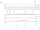
図1は、本発明による半透過PVAモードの液晶表示装置の一画素領域を示す平面図であり、図2は、図1のI−I´線における断面図であり、図3は、図1のII−II´線における断面図である。 FIG. 1 is a plan view showing one pixel region of a transflective PVA mode liquid crystal display device according to the present invention, FIG. 2 is a cross-sectional view taken along the line II ′ of FIG. 1, and FIG. It is sectional drawing in the II-II 'line.
液晶表示パネル300は、互いに対向する薄膜トランジスター基板100およびカラーフィルター基板200と、これらの間に位置する液晶層(図示せず)を備えてなる。
The liquid
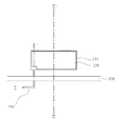
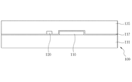
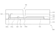
薄膜トランジスター基板100は、透過性絶縁基板である第1の絶縁基板111の上部に形成された活性層110と、活性層110の一部に連なって形成される第1の電極パターン115と、一方向に伸びる複数のゲート線120と、ゲート線120と平行して形成され、かつ、第1の電極パターン115と重なり合う第2の電極パターン130と、ゲート線120と直交する方向に伸びる複数のデータ線140と、データ線140の間に位置する画素領域Aに形成された画素電極150を備えてなる。ここで、画素領域Aは3領域、すなわち、画素領域Aの中央部の反射領域Bと、反射領域Bの両側の透過領域C1、C2により構成されている。すなわち、画素領域Aの中央部に、ゲート線120及び第2の電極パターン130が形成された反射領域Bが画定され、反射領域Bを除く残りの領域が画素領域Aとして画定される。反射領域Bを中心として透過領域Cは対称をなしている。また、反射領域Bに形成された画素電極150の上部または下部には、好ましくは、画素電極150よりも大面積の反射膜170をさらに備え、透過領域Cの画素電極150の好ましくは中央部には、円形の切欠部180をさらに備える。ここで、反射領域Bに形成された反射膜170は湾曲して形成することにより反射面をより広げることが好ましい。反射領域B及び2つの透過領域C1、C2により構成された単位画素領域Aは、それぞれの画素電極150が所定の間隔をおいて形成されることにより画定される。
The thin
活性層110は、データ線140と一部が重なったデータ線140の下部の任意の領域から第1の電極パターン115の任意の領域まで拡がって形成される。活性層110はゲート線120の下部に位置する。また、活性層110はデータ線140と第1のコンタクトホール190を通して接続され、画素電極150と第2のコンタクトホール195を通して接続される。そして、活性層110は、低温ポリシリコン薄膜により形成され、データ線140と第1のコンタクトホール190を通して接続される領域がソース領域110sとなり、画素電極150と第2のコンタクトホール195を通して接続される領域がドレイン領域となり、ソース領域110sおよびドレイン領域110dを除く残りの領域がチャンネル領域110cとなる。すなわち、低温ポリシリコン膜のソース領域110sおよびドレイン領域110dとなる領域には不純物によるイオン注入され、チャンネル領域110cの上部を通るゲート線120がゲート電極として機能することにより薄膜トランジスターが構成される。
The
第1の電極パターン115は、ストレジキャパシタの下部電極として機能するものであり、反射領域Bに、例えば、矩形に形成され、活性層110と同時に低温ポリシリコン膜により形成される。さらに、第1の電極パターン115は、活性層110のドレイン領域110dに連なって形成される。
The
ゲート線120は、所定の間隔をおいて複数横方向に伸びて形成される。また、ゲート線120は、ゲート絶縁膜117によって下部に形成された活性層110と絶縁される。
The gate lines 120 are formed extending in a plurality of lateral directions at a predetermined interval. The
第2の電極パターン130は、ストレジキャパシタの上部電極として機能するものであり、ゲート線120と同時に形成される。このとき、第2の電極パターン130は、第2のコンタクトホール195が形成される領域を除いては、第1の電極パターン115と重なって形成することが好ましい。第2の電極パターン130は、ゲート絶縁膜117を挟んで第1の電極パターン115とストレジキャパシタをなす。
The
第1の保護膜135は、ゲート線120が形成された絶縁基板111上全体に形成される。ここで、第1の保護膜135は、窒化シリコンまたは酸化シリコンなどの無機物質から形成されてもよく、低誘電率の有機絶縁膜から形成されてもよい。もちろん、無機絶縁膜と有機絶縁膜との2重膜に形成されてもよい。
The first
第1のコンタクトホール190は、活性層110のソース領域110sを露出させるために、第1の保護膜135及びゲート絶縁膜117の一部分を除去することによって形成される。
The
データ線140は、ゲート線120と直交するように一方向に伸びて形成され、その一部が第1のコンタクト190を通ってソース領域110sに接続される。これにより、データ線140は、ソース電極としての機能も兼ねる。
The
第2の保護膜145は、データ線140が形成された絶縁基板111上全体に形成される。ここでも、第2の保護膜145は、第1の保護膜135と同様に、窒化シリコンまたは酸化シリコンなどの無機物質から形成されてもよく、低誘電率の有機絶縁膜から形成されてもよい。もちろん、無機絶縁膜と有機絶縁膜との2重膜に形成されてもよい。また、第2の保護膜145は、反射領域Bにおいて湾曲させて形成することが好ましく、透過領域C1、C2においても湾曲させて形成してもよい。
The second
第2のコンタクトホール195は、活性層110のドレイン領域110dを露出させるために、第2の保護膜145、第1の保護膜135及びゲート絶縁膜117の一部を除去することによって形成される。
The
画素電極150はデータ線140の間に位置する画素領域Aに形成される。具体的には、反射領域Bと透過領域C1、C2にそれぞれ矩形の角部が丸く面取りされた形状に形成される。また、画素電極150は、第2のコンタクトホール195を通してドレイン領域110dに接続される。これにより、画素電極150は、ドレイン電極としての機能も兼ねる。なお、画素電極150は、インジウム錫酸化物(ITO)またはインジウム亜鉛酸化物(IZO)などの透明導電体から形成され、画素電極150と同時に形成された透明導電体製の接続部160により反射領域Bおよび透過領域C1、C2に形成された画素電極150B、150C1、150C2が互いに接続される。このように反射領域Bを挟んで透過領域C1、C2が画定され、各領域にそれぞれ画素電極150B、150C1、150C2が形成されるため、結果として、透過領域C1、C2の画素電極150C1、150C2が互いに隔離して形成されることとなる。よって、従来のように2つの透過領域が隣接していないため、2つの透過領域を隔離させるために2つの透過領域間に一定の距離を別途設ける必要がなく、結果として、その離隔に必要であった距離に対応する分だけ開口率の損失を抑えることができる。
The
反射膜170は、反射領域Bにおける画素電極150の上部または下部に形成されるが、反射領域Bに形成された画素電極150Bよりも大きい面積にて形成されることが好ましい。また、反射膜170は、湾曲させて形成された第2の保護膜145に沿って湾曲させて形成されることが好ましい。
The
また、透過領域C1、C2の画素電極150C1、150C2には、液晶の配列方向を整えるためのドメインコントロール手段として、切欠部180がそれぞれ形成される。切欠部180は、透過領域C1、C2の画素電極150C1、150C2の中央部に円形に形成されることが好ましい。これは、角部が丸く面取りされた矩形の画素電極150C1、150C2の液晶の配列方向を揃えるためである。さらに、画素電極150C1、150C2は、切欠部180の代わりに突起を備えてもよい。
The pixel electrodes 150C1 and 150C2 in the transmissive regions C1 and C2 are formed with
一方、カラーフィルター基板200は、第2の絶縁基板211の上にブラックマトリックス220と、カラーフィルター230と、オーバーコート膜240と、共通電極250とを備える。
On the other hand, the
ブラックマトリックス220は、薄膜トランジスター基板100の画素領域A以外の領域への光の漏れ、および隣り合う画素領域間の光干渉を防ぐために形成される。従って、ブラックマトリックス220は、薄膜トランジスター基板100の画素領域A以外の領域に対応する位置に形成される。すなわち、ブラックマトリックス220は、薄膜トランジスター基板100の画素領域Aを囲むように形成される。これにより、ブラックマトリックス220は、薄膜トランジスター基板100のデータ線140に対応する領域と、各画素電極150間の隙間に対応する領域に形成される。
The
カラーフィルター230には、ブラックマトリックス220を境界として赤色、緑色および青色フィルターが繰り返して形成される。カラーフィルター230は、液晶層(図示せず)を通過した光源からの光に色を付加する機能を有する。カラーフィルター230は、感光性の有機物質により形成される。
In the
オーバーコート膜240は、カラーフィルター230とカラーフィルター230に覆われていないブラックマトリックス220の上部に形成される。オーバーコート膜240は、アクリル系のエポキシ材料により形成され、カラーフィルター230を平坦化させるとともに、カラーフィルター230を保護する。
The
オーバーコート膜240の上部には共通電極250が形成される。共通電極250はITOまたはIZOなどの透明な導電物質により形成される。共通電極250には切欠パターン(図示せず)を形成してもよい。共通電極250の切欠パターン(図示せず)は、画素電極150の切欠部180とともに液晶層(図示せず)を多数の領域に分割する役割を果たす。
A
以下、図4Aから図8Cに基づき、本発明に係る液晶表示装置のうち薄膜トランジスター基板の製造方法を説明する。 Hereinafter, a method for manufacturing a thin film transistor substrate in the liquid crystal display device according to the present invention will be described with reference to FIGS. 4A to 8C.
図4A、図5A、図6A、図7A、図8Aは、本発明に係る薄膜トランジスター基板の製造工程を示す平面図であり、図4B、図5B、図6B、図7B、図8Bは、本発明に係る薄膜トランジスター基板の製造工程のI−I´線における断面図であり、図4C、図5C、図6C、図7C、図8Cは、本発明による薄膜トランジスター基板の製造工程のII−II´線における断面図である。 4A, FIG. 5A, FIG. 6A, FIG. 7A, and FIG. 8A are plan views showing the manufacturing process of the thin film transistor substrate according to the present invention, and FIG. 4B, FIG. 5B, FIG. FIG. 4C, FIG. 5C, FIG. 6C, FIG. 7C, and FIG. 8C are II-II of the manufacturing process of the thin-film transistor substrate by this invention, It is sectional drawing in the II 'line of the manufacturing process of the thin-film transistor substrate which concerns on invention. It is sectional drawing in a 'line.
図4A、図4Bおよび図4Cに示すように、まず、第1の絶縁基板111の上部に半導体層を形成する。半導体層は、低温ポリシリコン薄膜により形成するが、低温ポリシリコン薄膜は、非晶質シリコン薄膜を形成した後、低温下でポリシリコン薄膜に結晶化させることによって得る。ここで、非晶質シリコン薄膜を低温ポリシリコン薄膜に結晶化させるために汎用される方法としては、固相結晶化法(Solid Phase Crystallization;SPC)、エキシマレーザー結晶化法(Eximer Laser Crystallization;ELC)及び金属誘導結晶化法(Metal Induced Crystallization;MIC)などがある。次いで、第1のマスクを用いたフォト工程およびエッチング工程により半導体層をパターニングする。半導体層は所定の領域において矩形にパターニングされる。ここから所定の幅をもって伸長すなわち、半導体層は、矩形にパターニングされた領域から、後にデータ線140が形成される領域まで伸長され、このとき、後にゲート線120が形成される領域を通る。ここで、矩形にパターニングされた半導体層は第1の電極パターン115となり、ここから所定の幅をもって伸長された半導体層は薄膜トランジスターのソース領域、ドレイン領域及びチャンネル領域が形成される活性層110となる。そして、活性層110の所定の領域、すなわち、データ線140が形成される領域と重なる領域及び第1の電極パターン115と連なる領域に不純物によるイオン注入がなされる。不純物によるイオン注入がされた後、エキシマレーザーなどを用いてイオン注入された不純物を活性化させる。ここで、不純物がイオン注入された活性層110の領域はそれぞれソース領域110s及びドレイン領域110dとなり、それ以外の領域はチャンネル領域110cとなる。前記工程により薄膜トランジスター110及び第1の電極パターン115が形成される。なお、第1の電極パターン115にも不純物によるイオン注入がされ得る。
As shown in FIGS. 4A, 4B, and 4C, first, a semiconductor layer is formed on the first insulating
図5A、図5B及び図5Cに示すように、ソース領域110s、ドレイン領域110dおよびチャンネル領域110cが形成された活性層110および第1の電極パターン115が形成された第1の絶縁基板111の上部全体にゲート絶縁膜117を形成する。ゲート絶縁膜117は、例えば、酸化シリコンまたは窒化シリコンなどのシリコン系の絶縁体により形成する。次いで、第1の絶縁基板111の上部全体に第1の導電層を形成する。ここで、第1の導電層は、アルミニウム(Al)、ネオジム(Nd)、銀(Ag)、クロム(Cr)、チタン(Ti)、タンタル(Ta)およびモリブデン(Mo)よりなる群から選ばれた少なくとも1種の金属またはこれらの合金により形成することが好ましい。また、第1の導電層は、単一層に形成されても、複数の金属層よりなる多重層に形成されてもよい。すなわち、物理的、化学的な特性に優れたクロム(Cr)、チタン(Ti)、タンタル(Ta)、モリブデン(Mo)などの金属層と、比抵抗の低いアルミニウム(Al)系または銀(Ag)系の金属層とからなる2重層として形成することもできる。そして、第2のマスクを用いたフォト工程およびエッチング工程により第1の導電層をパターニングしてゲート線120および第2の電極パターン130を形成する。ここで、ゲート線120は、一方向に伸びて複数形成される。また、第2の電極パターン130は、ゲート線120と所定の間隔を隔てて、ドレイン領域110dを露出させるとともに、第1の電極パターン115と重なるように形成される。なお、第2の電極パターン130は、ゲート絶縁膜117を挟んで第1の電極パターン115とともにストレジキャパシタをなす。
As shown in FIGS. 5A, 5B, and 5C, the
図6A、図6B及び図6Cに示すように、ゲート線120及び第2の電極パターン130が形成された第1の絶縁基板111の上部全体に第1の保護膜135を形成する。ここで、第1の保護膜135は、窒化シリコンまたは酸化シリコンなどの無機物質から形成されてもよく、低誘電率の有機絶縁膜から形成されてもよく、さらには、無機絶縁膜と有機絶縁膜との2重膜から形成されてもよい。第3のマスクを用いたフォト工程およびエッチング工程により、第1の保護膜135およびその下部のゲート絶縁膜117をエッチングして、活性層110のソース領域110sを露出させることにより第1のコンタクトホール190を形成する。次に、第1の絶縁基板111の上部全体に第2の導電層を形成する。第2の導電層は、第1の導電層をなす物質と同じ物質により形成し得る。第4のマスクを用いたフォト工程およびエッチング工程により第2の導電層をパターニングして、データ線140を形成する。データ線140は、ゲート線120と垂直な方向に伸びて形成される。また、第2の導電層が第1のコンタクトホール190を通じてソース領域110sに接続される。これにより、データ線140は、ソース電極としての機能も兼ねる。
As shown in FIGS. 6A, 6B, and 6C, a first
図7A、図7Bおよび図7Cに示すように、データ線140が形成された第1の絶縁基板111の上部全体に第2の保護膜145を形成する。第2の保護膜145は、第1の保護膜135と同様に、窒化シリコンまたは酸化シリコンなどの無機物質から形成されてもよく、低誘電率の有機絶縁膜から形成されてもよく、さらには、無機絶縁膜と有機絶縁膜との2重膜から形成されてもよい。また、反射領域Bの第2の保護膜145は湾曲して形成されることが好ましく、透過領域C1、C2の第2の保護膜145も湾曲して形成されることが好ましい。次いで、第5のマスクを用いたフォト工程およびエッチング工程により第2の保護膜145、第1の保護膜135およびゲート絶縁膜117をエッチングして、活性層110のドレイン領域110dを露出させることにより第2のコンタクトホール195を形成する。
As shown in FIGS. 7A, 7B, and 7C, a second
図8A、図8B及び図8Cに示すように、第2のコンタクトホール195が形成された第1の絶縁基板111の上部全体に第3の導電層を形成する。そして、第6のマスクを用いたフォト工程およびエッチング工程により第3の導電層をパターニングして画素電極150を形成する。画素電極150は、データ線140の間に位置する画素領域Aに形成し、また、隣り合う画素電極とは所定の間隔離して形成する。画素領域Aは、ゲート線120および第2の電極パターン130が通る画素領域Aの中央部の反射領域Bと、反射領域Bの両側の透過領域C1、C2により構成される。また、反射領域Bと透過領域C1、C2に形成された画素電極150B、150C1、150C2はそれぞれ矩形の角部が丸く面取りされた形状に形成される。反射領域Bと透過領域C1、C2に形成された画素電極150は接続部160により電気的に接続されるが、接続部160は、第4の導電層をパターニングして画素電極150を形成するときに同時に形成される。また、画素電極150は、第2のコンタクトホール195を介してドレイン領域110dに接続される。これにより、画素電極150は、ドレイン電極としての機能も兼ねる。なお、画素電極150および接続部160を形成するための第4の導電層は、ITOまたはIZOなどの透明導電体により形成する。また、画素電極150をパターニングするとき、透過領域C1、C2における画素電極150C1150C2の中央部には円形の切欠部180を形成することが好ましい。次に、第1の絶縁基板111の上部全体に反射膜170を形成した後、第7のマスクを用いたフォト工程およびエッチング工程により反射領域Bにのみ反射膜170を残す。このとき、反射膜170は、反射領域Bに形成された画素電極150よりも大きな面積に形成することが好ましく、湾曲して形成された第2の保護膜145に沿って湾曲して形成されることが好ましい。ここで、反射膜170は、光反射率に優れた銀(Ag)、アルミニウム(Al)、金(Au)、ネオジム(Nd)及び銅(Cu)よりなる群から選ばれた少なくとも1種の金属からなる単一層または多重層を用いて形成することができる。
As shown in FIGS. 8A, 8B, and 8C, a third conductive layer is formed on the entire upper portion of the first insulating
上記のような薄膜トランジスター基板100の製造とは別に、カラーフィルター基板200を製造する。カラーフィルター基板200を製造するために、第2の絶縁基板211の所定の領域、すなわち、薄膜トランジスター基板100における画素電極150が形成されない領域に対応する領域にブラックマトリックス220を形成し、画素電極150が形成される領域に対応する領域にカラーフィルター230を形成する。そして、ブラックマトリックス220とカラーフィルター230との段差を無くすためにオーバーコート膜240を形成する。この後、カラーフィルター基板200の全面に共通電極250を形成する。
A
このようにして製造された薄膜トランジスター基板100とカラーフィルター基板200を、それぞれの画素電極150と共通電極250を互いに対向するようにして封止する。このとき、2枚の基板の封止のために、所定のシール膜が塗布される。そして、2枚の基板間のセルギャップを維持するためにスペーサーが設けられることもできる。この後、組み合わせられた2枚の基板の間に液晶を封入して液晶表示パネル300を製作する。
The thin
このようにして製作された液晶表示パネルによれば、薄膜トランジスター基板100の薄膜トランジスター110を通して画素の形成に必要な電気的信号を画素電極150に印加し、カラーフィルター基板200の共通電極250に共通電圧を印加することにより、画素電極150と共通電極250との間に電界が形成される。このような電界により液晶層の配列が変わり、変わった配列により光透過度が変更されて目的とする画像を表示することが可能になる。
According to the liquid crystal display panel thus manufactured, an electrical signal necessary for forming a pixel is applied to the
本発明は、主に薄型テレビジョンや、パーソナルコンピュータのディスプレイ、携帯電話などの製造分野に利用されるが、他の分野においても本発明の技術的思想の範囲において適用され得る。 The present invention is mainly used in the manufacturing field of flat-screen televisions, personal computer displays, mobile phones, and the like, but can be applied to other fields within the scope of the technical idea of the present invention.
A 画素領域、
B 反射領域、
C1、C2 透過領域、
100 薄膜トランジスター基板、
110 活性層、
110s ソース領域、
110c チャンネル、
110d ドレイン領域、
115 第1の電極パターン、
117 ゲート絶縁膜、
120 ゲート線、
130 第2の電極パターン、
135 第1の保護膜、
140 データ線、
145 第2の保護膜、
150 画素電極、
160 接続部、
170 反射膜、
180 切欠部、
200 カラーフィルター基板、
211 第2の絶縁基板、
220 ブラックマトリックス、
230 カラーフィルター、
240 オーバーコート膜、
250 共通電極、
300 液晶表示パネル。
A pixel area,
B reflection area,
C1, C2 transmission region,
100 thin film transistor substrate,
110 active layer,
110s source region,
110c channel,
110d drain region,
115 first electrode pattern;
117 gate insulating film,
120 gate lines,
130 second electrode pattern;
135 first protective film,
140 data lines,
145 second protective film,
150 pixel electrodes,
160 connections,
170 reflective film,
180 notch,
200 color filter substrate,
211 a second insulating substrate,
220 black matrix,
230 color filter,
240 overcoat film,
250 common electrodes,
300 Liquid crystal display panel.
Claims (4)
前記ゲート線と交差して形成された複数のデータ線と、
前記データ線の間に位置する画素領域に形成された複数の画素電極と、を備え、
各画素領域は、
前記ゲート線を含む領域に形成された反射領域と、
前記反射領域を挟んで両側に形成された透過領域と、
前記基板上の任意の領域に形成された第1の電極パターンと、
前記第1の電極パターンと同一層で形成されて連なることで接続され、前記ゲート線の下を通って前記データ線に接続された活性層と、を備え、
前記活性層は、
前記データ線に接続されたソース領域と、
前記画素電極に接続されたドレイン領域と、
前記ソース領域及びドレイン領域の間であって、上部に前記ゲート線を有するチャンネル領域と、
前記ゲート線と所定の間隔を隔てて形成された前記ストレジキャパシタの上部電極をなす第2の電極パターンと、を備え、
前記第2の電極パターンは、前記活性層と接続される部分を除き、前記第1の電極パターンと重なり合うように形成され、
前記画素電極は、それぞれ角部が丸く面取りされた矩形形状を有し、前記反射領域および前記透過領域にそれぞれ形成されるとともに、接合部により電気的に接続され、
前記ゲート線は前記反射領域と前記透過領域との境界のいずれか一方に沿って伸び、前記反射領域と重畳するように設けられていることを特徴とする薄膜トランジスター基板。 A plurality of gate lines formed extending in one direction on the substrate;
A plurality of data lines formed to intersect the gate lines;
A plurality of pixel electrodes formed in a pixel region located between the data lines,
Each pixel area
A reflective region formed in a region including the gate line;
A transmissive region formed on both sides across the reflective region;
A first electrode pattern formed in an arbitrary region on the substrate;
The first electrode pattern is formed in the same layer and connected by being connected, and an active layer connected to the data line through the gate line, and
The active layer is
A source region connected to the data line;
A drain region connected to the pixel electrode;
A channel region between the source region and drain region and having the gate line on top;
A second electrode pattern that forms an upper electrode of the storage capacitor formed at a predetermined interval from the gate line, and
The second electrode pattern is formed so as to overlap the first electrode pattern except for a portion connected to the active layer,
Each of the pixel electrodes has a rectangular shape with rounded corners and is formed in each of the reflective region and the transmissive region, and is electrically connected by a joint.
The gate line extends along one of the boundary between the transmission region and the reflection region, a thin film transistor substrate, wherein that you have provided so as to overlap the reflective region.
前記ゲート線と交差して形成された複数のデータ線と、
前記データ線の間に位置する画素領域に形成された複数の画素電極と、を備え、
各画素領域は、
前記ゲート線を含む領域に形成された反射領域と、
前記反射領域を挟んで両側に形成された透過領域と、
前記基板上の任意の領域に形成された第1の電極パターンと、
前記第1の電極パターンと同一層で形成されて連なることで接続され、前記ゲート線の下を通って前記データ線に接続された活性層と、を備え、
前記活性層は、
前記データ線に接続されたソース領域と、
前記画素電極に接続されたドレイン領域と、
前記ソース領域及びドレイン領域の間であって、上部に前記ゲート線を有するチャンネル領域と、
前記ゲート線と所定の間隔を隔てて形成された前記ストレジキャパシタの上部電極をなす第2の電極パターンと、を備え、
前記第2の電極パターンは、前記活性層と接続される部分を除き、前記第1の電極パターンと重なり合うように形成され、
前記画素電極は、それぞれ角部が丸く面取りされた矩形形状を有し、前記反射領域および前記透過領域にそれぞれ形成されるとともに、接合部により電気的に接続され、
前記ゲート線は前記反射領域と前記透過領域との境界のいずれか一方に沿って伸び、前記反射領域と重畳するように設けられている薄膜トランジスター基板と、
前記画素領域以外の領域に対応する第2の基板上の領域に形成されたブラックマトリックスと、前記画素領域に対応する前記第2の基板上の領域に形成されたカラーフィルターと、前記第2の基板上に形成された共通電極と、を備えるカラーフィルター基板と、
前記薄膜トランジスター基板と前記カラーフィルター基板との間に形成された液晶層と、
を備えることを特徴とする液晶表示装置。 A plurality of gate lines formed extending in one direction on the substrate;
A plurality of data lines formed to intersect the gate lines;
A plurality of pixel electrodes formed in a pixel region located between the data lines,
Each pixel area
A reflective region formed in a region including the gate line;
A transmissive region formed on both sides across the reflective region;
A first electrode pattern formed in an arbitrary region on the substrate;
The first electrode pattern is formed in the same layer and connected by being connected, and an active layer connected to the data line through the gate line, and
The active layer is
A source region connected to the data line;
A drain region connected to the pixel electrode;
A channel region between the source region and drain region and having the gate line on top;
A second electrode pattern that forms an upper electrode of the storage capacitor formed at a predetermined interval from the gate line, and
The second electrode pattern is formed so as to overlap the first electrode pattern except for a portion connected to the active layer,
Each of the pixel electrodes has a rectangular shape with rounded corners and is formed in each of the reflective region and the transmissive region, and is electrically connected by a joint.
The gate line extends along one of the boundaries between the reflective region and the transmissive region, and is a thin film transistor substrate provided so as to overlap the reflective region;
A black matrix formed in a region on a second substrate corresponding to a region other than the pixel region, a color filter formed in a region on the second substrate corresponding to the pixel region, and the second A color filter substrate comprising a common electrode formed on the substrate;
A liquid crystal layer formed between the thin film transistor substrate and the color filter substrate;
A liquid crystal display device comprising:
Applications Claiming Priority (2)
| Application Number | Priority Date | Filing Date | Title |
|---|---|---|---|
| KR10-2006-0112859 | 2006-11-15 | ||
| KR1020060112859A KR20080044050A (en) | 2006-11-15 | 2006-11-15 | Thin film transistor and method of manufacturing the same, and liquid crystal display having the same |
Publications (3)
| Publication Number | Publication Date |
|---|---|
| JP2008122904A JP2008122904A (en) | 2008-05-29 |
| JP2008122904A5 JP2008122904A5 (en) | 2010-05-27 |
| JP5240749B2 true JP5240749B2 (en) | 2013-07-17 |
Family
ID=39368864
Family Applications (1)
| Application Number | Title | Priority Date | Filing Date |
|---|---|---|---|
| JP2007103001A Active JP5240749B2 (en) | 2006-11-15 | 2007-04-10 | Thin film transistor substrate, method for manufacturing the same, and liquid crystal display device including the same |
Country Status (4)
| Country | Link |
|---|---|
| US (1) | US7995171B2 (en) |
| JP (1) | JP5240749B2 (en) |
| KR (1) | KR20080044050A (en) |
| CN (1) | CN101226944B (en) |
Families Citing this family (5)
| Publication number | Priority date | Publication date | Assignee | Title |
|---|---|---|---|---|
| JP5623107B2 (en) * | 2009-04-22 | 2014-11-12 | キヤノン株式会社 | Semiconductor device |
| KR101822563B1 (en) * | 2010-12-08 | 2018-03-09 | 삼성디스플레이 주식회사 | Organic light emitting display device and manufacturing method of the same |
| CN102981324B (en) | 2012-12-10 | 2017-07-14 | 京东方科技集团股份有限公司 | A kind of semi-transparent semi-reflecting blue-phase liquid crystal display panel and liquid crystal display device |
| CN103107095A (en) * | 2013-01-25 | 2013-05-15 | 京东方科技集团股份有限公司 | Thin film transistor, manufacturing method of thin film transistor, array substrate and display device |
| CN104269410A (en) * | 2014-09-03 | 2015-01-07 | 合肥京东方光电科技有限公司 | Array substrate and display device |
Family Cites Families (21)
| Publication number | Priority date | Publication date | Assignee | Title |
|---|---|---|---|---|
| US6195140B1 (en) * | 1997-07-28 | 2001-02-27 | Sharp Kabushiki Kaisha | Liquid crystal display in which at least one pixel includes both a transmissive region and a reflective region |
| JP4196505B2 (en) * | 1999-12-13 | 2008-12-17 | ソニー株式会社 | Display device, manufacturing method thereof, and color filter |
| JP3892715B2 (en) * | 2000-12-26 | 2007-03-14 | 株式会社東芝 | Liquid crystal display |
| JP4603190B2 (en) | 2001-04-16 | 2010-12-22 | 株式会社日立製作所 | Liquid crystal display |
| JP4050119B2 (en) * | 2001-10-02 | 2008-02-20 | シャープ株式会社 | Liquid crystal display |
| KR20030058012A (en) | 2001-12-29 | 2003-07-07 | 엘지.필립스 엘시디 주식회사 | transflective liquid crystal displays |
| KR100752214B1 (en) * | 2003-10-16 | 2007-08-28 | 엘지.필립스 엘시디 주식회사 | Method For Fabricating Transflective Type Liquid Crystal Display Device |
| KR100617031B1 (en) * | 2003-12-30 | 2006-08-30 | 엘지.필립스 엘시디 주식회사 | Trans-reflective liquid crystal display device and method for fabricating the same |
| KR100715756B1 (en) * | 2004-03-09 | 2007-05-08 | 샤프 가부시키가이샤 | Liquid crystal display device |
| JP4390595B2 (en) * | 2004-03-09 | 2009-12-24 | シャープ株式会社 | Liquid crystal display |
| JP3915792B2 (en) | 2004-03-12 | 2007-05-16 | セイコーエプソン株式会社 | Liquid crystal display device and electronic device |
| JP4738055B2 (en) * | 2004-05-21 | 2011-08-03 | 三洋電機株式会社 | Liquid crystal display |
| JP4873882B2 (en) | 2004-05-21 | 2012-02-08 | 三洋電機株式会社 | Liquid crystal display |
| JP3953059B2 (en) * | 2004-09-01 | 2007-08-01 | セイコーエプソン株式会社 | Liquid crystal display device and electronic device |
| JP4016977B2 (en) * | 2004-09-03 | 2007-12-05 | セイコーエプソン株式会社 | Liquid crystal display device, electronic equipment |
| KR20060034802A (en) | 2004-10-19 | 2006-04-26 | 삼성전자주식회사 | Transflective liquid crystal display |
| JP4427436B2 (en) | 2004-11-25 | 2010-03-10 | シャープ株式会社 | Liquid crystal display |
| JP4578958B2 (en) | 2004-12-16 | 2010-11-10 | シャープ株式会社 | Liquid crystal display |
| KR101151799B1 (en) * | 2005-11-09 | 2012-06-01 | 엘지디스플레이 주식회사 | An array substrate of LCD and Method of fabricating of the same |
| JP2007133293A (en) * | 2005-11-14 | 2007-05-31 | Epson Imaging Devices Corp | Liquid crystal device and electronic apparatus |
| JP4341617B2 (en) | 2005-12-02 | 2009-10-07 | セイコーエプソン株式会社 | Liquid crystal display device and electronic device |
-
2006
- 2006-11-15 KR KR1020060112859A patent/KR20080044050A/en not_active Application Discontinuation
-
2007
- 2007-04-10 JP JP2007103001A patent/JP5240749B2/en active Active
- 2007-11-14 US US11/940,067 patent/US7995171B2/en active Active
- 2007-11-15 CN CN2007103007676A patent/CN101226944B/en active Active
Also Published As
| Publication number | Publication date |
|---|---|
| CN101226944A (en) | 2008-07-23 |
| US7995171B2 (en) | 2011-08-09 |
| JP2008122904A (en) | 2008-05-29 |
| KR20080044050A (en) | 2008-05-20 |
| US20080111956A1 (en) | 2008-05-15 |
| CN101226944B (en) | 2013-07-03 |
Similar Documents
| Publication | Publication Date | Title |
|---|---|---|
| JP5307319B2 (en) | Thin film transistor array panel and manufacturing method thereof | |
| KR101413275B1 (en) | Liquid crystal display panel and method of manufacturing the same | |
| JP5351388B2 (en) | Display device | |
| US7688417B2 (en) | Thin film transistor array panel and method for manufacturing the same | |
| JP5132894B2 (en) | Display board and liquid crystal display device including the same | |
| TWI383234B (en) | Thin film transistor array panel and manufacturing method thereof | |
| JP2006133783A (en) | Multiplex domain thin-film transistor display panel | |
| US8300166B2 (en) | Display panel and method of manufacturing the same | |
| JP2006201775A (en) | Thin film transistor array panel, liquid crystal display including the panel and its manufacturing method | |
| JP5652841B2 (en) | Thin film transistor display panel | |
| JP4813050B2 (en) | Display plate and liquid crystal display device including the same | |
| JP5295483B2 (en) | Thin film transistor display panel | |
| JP2006023744A5 (en) | ||
| JP5240749B2 (en) | Thin film transistor substrate, method for manufacturing the same, and liquid crystal display device including the same | |
| US20070188682A1 (en) | Method for manufacturing a display device | |
| JP2006178445A (en) | Thin film transistor array panel and manufacturing method thereof | |
| JP2005018069A (en) | Liquid crystal display device | |
| KR20080073573A (en) | Liquid crystal panel and manufacturing method thereof | |
| KR20020011574A (en) | array panel for liquid crystal display and fabricating method of the same | |
| JP2007017756A (en) | Liquid crystal display device | |
| JP2007011372A (en) | Liquid crystal display | |
| US8841677B2 (en) | Thin film transistor array panel and manufacturing method thereof | |
| KR20070031580A (en) | Liquid crystal display | |
| KR20080034634A (en) | Thin film transistor substrate and method of manufacturing the same, and liquid crystal display having the same | |
| KR20090005258A (en) | Method of manufacturing a liquid crystal display panel |
Legal Events
| Date | Code | Title | Description |
|---|---|---|---|
| A521 | Request for written amendment filed |
Free format text: JAPANESE INTERMEDIATE CODE: A523 Effective date: 20100409 |
|
| A621 | Written request for application examination |
Free format text: JAPANESE INTERMEDIATE CODE: A621 Effective date: 20100409 |
|
| A977 | Report on retrieval |
Free format text: JAPANESE INTERMEDIATE CODE: A971007 Effective date: 20120125 |
|
| A131 | Notification of reasons for refusal |
Free format text: JAPANESE INTERMEDIATE CODE: A131 Effective date: 20120207 |
|
| A601 | Written request for extension of time |
Free format text: JAPANESE INTERMEDIATE CODE: A601 Effective date: 20120507 |
|
| A602 | Written permission of extension of time |
Free format text: JAPANESE INTERMEDIATE CODE: A602 Effective date: 20120510 |
|
| A521 | Request for written amendment filed |
Free format text: JAPANESE INTERMEDIATE CODE: A523 Effective date: 20120607 |
|
| A711 | Notification of change in applicant |
Free format text: JAPANESE INTERMEDIATE CODE: A712 Effective date: 20121213 |
|
| TRDD | Decision of grant or rejection written | ||
| A01 | Written decision to grant a patent or to grant a registration (utility model) |
Free format text: JAPANESE INTERMEDIATE CODE: A01 Effective date: 20130319 |
|
| A61 | First payment of annual fees (during grant procedure) |
Free format text: JAPANESE INTERMEDIATE CODE: A61 Effective date: 20130327 |
|
| FPAY | Renewal fee payment (event date is renewal date of database) |
Free format text: PAYMENT UNTIL: 20160412 Year of fee payment: 3 |
|
| R150 | Certificate of patent or registration of utility model |
Free format text: JAPANESE INTERMEDIATE CODE: R150 Ref document number: 5240749 Country of ref document: JP Free format text: JAPANESE INTERMEDIATE CODE: R150 |
|
| R250 | Receipt of annual fees |
Free format text: JAPANESE INTERMEDIATE CODE: R250 |
|
| R250 | Receipt of annual fees |
Free format text: JAPANESE INTERMEDIATE CODE: R250 |
|
| R250 | Receipt of annual fees |
Free format text: JAPANESE INTERMEDIATE CODE: R250 |
|
| R250 | Receipt of annual fees |
Free format text: JAPANESE INTERMEDIATE CODE: R250 |
|
| R250 | Receipt of annual fees |
Free format text: JAPANESE INTERMEDIATE CODE: R250 |
|
| R250 | Receipt of annual fees |
Free format text: JAPANESE INTERMEDIATE CODE: R250 |
|
| R250 | Receipt of annual fees |
Free format text: JAPANESE INTERMEDIATE CODE: R250 |
|
| R250 | Receipt of annual fees |
Free format text: JAPANESE INTERMEDIATE CODE: R250 |
|
| R250 | Receipt of annual fees |
Free format text: JAPANESE INTERMEDIATE CODE: R250 |