JP5231917B2 - Deposition equipment - Google Patents
Deposition equipment Download PDFInfo
- Publication number
- JP5231917B2 JP5231917B2 JP2008246503A JP2008246503A JP5231917B2 JP 5231917 B2 JP5231917 B2 JP 5231917B2 JP 2008246503 A JP2008246503 A JP 2008246503A JP 2008246503 A JP2008246503 A JP 2008246503A JP 5231917 B2 JP5231917 B2 JP 5231917B2
- Authority
- JP
- Japan
- Prior art keywords
- link
- vacuum
- substrate
- moving
- forming apparatus
- Prior art date
- Legal status (The legal status is an assumption and is not a legal conclusion. Google has not performed a legal analysis and makes no representation as to the accuracy of the status listed.)
- Expired - Fee Related
Links
- 230000008021 deposition Effects 0.000 title claims description 22
- 239000000758 substrate Substances 0.000 claims description 63
- 238000001704 evaporation Methods 0.000 claims description 29
- 230000008020 evaporation Effects 0.000 claims description 23
- 239000000463 material Substances 0.000 claims description 17
- 239000012530 fluid Substances 0.000 claims description 10
- 238000001816 cooling Methods 0.000 claims description 9
- 229910052751 metal Inorganic materials 0.000 claims description 7
- 239000002184 metal Substances 0.000 claims description 7
- 229910001220 stainless steel Inorganic materials 0.000 claims description 7
- 239000010935 stainless steel Substances 0.000 claims description 7
- 229910052782 aluminium Inorganic materials 0.000 claims description 3
- XAGFODPZIPBFFR-UHFFFAOYSA-N aluminium Chemical compound [Al] XAGFODPZIPBFFR-UHFFFAOYSA-N 0.000 claims description 3
- 238000012545 processing Methods 0.000 description 31
- 238000007740 vapor deposition Methods 0.000 description 25
- 238000000151 deposition Methods 0.000 description 20
- 238000000034 method Methods 0.000 description 19
- 238000004519 manufacturing process Methods 0.000 description 15
- 238000012546 transfer Methods 0.000 description 12
- 238000001771 vacuum deposition Methods 0.000 description 10
- 239000000498 cooling water Substances 0.000 description 8
- 239000010408 film Substances 0.000 description 8
- 238000010586 diagram Methods 0.000 description 6
- XLYOFNOQVPJJNP-UHFFFAOYSA-N water Substances O XLYOFNOQVPJJNP-UHFFFAOYSA-N 0.000 description 3
- 239000013078 crystal Substances 0.000 description 2
- 238000002347 injection Methods 0.000 description 2
- 239000007924 injection Substances 0.000 description 2
- JEIPFZHSYJVQDO-UHFFFAOYSA-N iron(III) oxide Inorganic materials O=[Fe]O[Fe]=O JEIPFZHSYJVQDO-UHFFFAOYSA-N 0.000 description 2
- 238000010943 off-gassing Methods 0.000 description 2
- 238000005192 partition Methods 0.000 description 2
- 238000002360 preparation method Methods 0.000 description 2
- 238000011084 recovery Methods 0.000 description 2
- 239000011347 resin Substances 0.000 description 2
- 229920005989 resin Polymers 0.000 description 2
- 238000007789 sealing Methods 0.000 description 2
- 241000221535 Pucciniales Species 0.000 description 1
- 239000000654 additive Substances 0.000 description 1
- 230000000996 additive effect Effects 0.000 description 1
- 239000011248 coating agent Substances 0.000 description 1
- 238000000576 coating method Methods 0.000 description 1
- 238000007796 conventional method Methods 0.000 description 1
- 230000000694 effects Effects 0.000 description 1
- 230000002452 interceptive effect Effects 0.000 description 1
- 230000005389 magnetism Effects 0.000 description 1
- 238000012856 packing Methods 0.000 description 1
- 230000001360 synchronised effect Effects 0.000 description 1
- 239000010409 thin film Substances 0.000 description 1
- 238000005019 vapor deposition process Methods 0.000 description 1
Images


Description
本発明は、有機ELデバイス製造装置及び成膜装置並びに真空内配線・配管機構に係わり、特に真空チャンバの真空維持、流体漏洩防止に好適な有機ELデバイス製造装置及び成膜装置並びに真空内配線・配管機構に関する。 The present invention relates to an organic EL device manufacturing apparatus, a film forming apparatus, and an in-vacuum wiring / piping mechanism, and more particularly to an organic EL device manufacturing apparatus, a film forming apparatus, an in-vacuum wiring, It relates to a piping mechanism.
有機ELデバイスを製造する有力な方法として真空蒸着法がある。真空蒸着工程などの真空を利用する機構において、その真空チャンバ中に繰り返し移動する機構を有し、且つその移動体に配線、配管を施す必要がある。その場合、大気中で使用するような一般的な動的結束具(ex.ケーブルベア(登録商標))などを用いて真空中に暴露することは、(1)配線の被覆材質からのアウトガスの問題や、(2)配管疲労による損傷がもたらす流体漏洩の恐れなど、の理由から、通常難しいとされている。特に有機ELデバイス製造装置は、水漏洩に対してデリケートであり、再度所定の真空度を得るのに時間がかかる。この課題に対する従来技術としては下記のものがある。
There exists a vacuum evaporation method as an influential method of manufacturing an organic EL device. In a mechanism using vacuum, such as a vacuum deposition process, it is necessary to have a mechanism that repeatedly moves into the vacuum chamber, and to provide wiring and piping to the moving body. In that case, exposure to the vacuum using a general dynamic tying tool (ex. Cableveyor (registered trademark) ) used in the atmosphere will cause (1) outgas from the coating material of the wiring. problems and, (2), such as fear of fluid leakage resulting damage due to pipeline fatigue, the reasons are usually difficult. In particular, the organic EL device manufacturing apparatus is sensitive to water leakage, and it takes time to obtain a predetermined degree of vacuum again. Conventional techniques for this problem include the following.
特許文献1は、移動装置を磁気によって大気側から駆動することによってモータのリード線や信号線等を真空チャンバ内に引き回さないようにすることを開示している。
特許文献2は、配線や配管を柔軟性の高い樹脂性の配管で覆い、被覆配管内を真空排気することを開示している。
しかしながら、特許文献1に開示された方法は、流体配管には適用できない。また、特許文献2に開示された発明は、次のような課題がある。まず、第一に、被覆配管に樹脂を使用しているためにアウトガスの問題を完全に払拭できない。第二に、配線に樹脂を使用しているために被覆配管内を真空排気する必要がある。第三に高速移動する移動体に適用した場合、被覆配管の疲労損傷の問題を払拭できない。
However, the method disclosed in
従って、本発明の第一の目的は、アウトガスや配管の疲労損傷の問題を払拭できる信頼性の高い真空内配線・配管機構を提供することである。
また、本発明の第二の目的は、真空排気の必要のない真空内配線・配管機構を提供することである。
さらに、本発明三の目的は、本発明の真空内配線・配管機構を使用することによって、信頼性の高い有機ELデバイス製造装置及び成膜装置を提供することである。
Accordingly, a first object of the present invention is to provide a highly reliable in-vacuum wiring / piping mechanism that can eliminate the problem of outgassing and fatigue damage of piping.
A second object of the present invention is to provide an in-vacuum wiring / piping mechanism that does not require evacuation.
A third object of the present invention is to provide a highly reliable organic EL device manufacturing apparatus and film forming apparatus by using the in-vacuum wiring / piping mechanism of the present invention.
上記目的を達成するために、複数の真空チャンバと、前記複数の真空チャンバ内のうち少なくとも一つの真空チャンバ内に移動部を有し、蒸着材料を基板に蒸着する有機ELデバイス製造装置あるいは成膜装置において、中空のリンクで構成し、前記中空のリンク内に前記移動部への配線または流体を流す配管のうち少なくとも一方を敷設し、一端を大気に開放し、他端を前記移動部に接続した真空内配線・配管機構を有することを第1の特徴とする。 In order to achieve the above object, an organic EL device manufacturing apparatus or a film forming apparatus that includes a plurality of vacuum chambers and a moving unit in at least one of the plurality of vacuum chambers, and deposits a deposition material on a substrate. In the apparatus, it is constituted by a hollow link, and at least one of wiring to the moving part or piping for flowing fluid is laid in the hollow link, one end is opened to the atmosphere, and the other end is connected to the moving part The first feature is to have the in-vacuum wiring / piping mechanism.
また、上記目的を達成するために、第1の特徴に加え、前記リンクの可動部、移動体への接続部及び大気への接続部を真空シールすることを第2の特徴とする。
また、上記目的を達成するために、第1の特徴に加え、前記リンクは錆び難くアウトガスが少ない金属製であることを第3の特徴とする。
In order to achieve the above object, in addition to the first feature, a second feature is to vacuum seal the movable portion of the link, the connection portion to the moving body, and the connection portion to the atmosphere.
In order to achieve the above object, in addition to the first feature, the third feature is that the link is made of a metal that hardly rusts and has little outgas.
さらに、上記目的を達成するために、第1の特徴に加え、前記移動体は、前記蒸着材料を蒸発する蒸発源を移動させる移動体であることを第4の特徴とする。
また、上記目的を達成するために、前記移動体は前記基板を載置した位置から蒸着位置に移動する移動体であり、前記配管は前記基板を冷却する前記移動体上の冷却部に流体を供給・回収する配管であることを第5の特徴とする請求項1に記載の有機ELデバイス製造装置。
Furthermore, in order to achieve the above object, in addition to the first feature, the moving body is a moving body that moves an evaporation source for evaporating the vapor deposition material.
In order to achieve the above object, the moving body is a moving body that moves from a position on which the substrate is placed to a deposition position, and the pipe supplies fluid to a cooling unit on the moving body that cools the substrate. 5. The organic EL device manufacturing apparatus according to
また、上記目的を達成するために、中空のリンク内に配線または流体を流す配管のうち少なくとも一方を敷設するものであって、前記リンクの可動部及び前記リンクの両端のうち少なくとも一端を真空シールするシール部を有する真空内配線・配管機構を第6の特徴とする。 Further, in order to achieve the above object, at least one of wiring or piping for flowing fluid is laid in a hollow link, and at least one end of the movable part of the link and both ends of the link is vacuum-sealed. A sixth feature is an in-vacuum wiring / piping mechanism having a sealing portion.
本発明によれば、アウトガスや配管の疲労損傷の問題を払拭できる信頼性の高い真空内駆動装置を提供することである。
また、本発明によれば、真空排気の必要のない真空内駆動装置を提供することである。
さらに、本発明によれば、信頼性の高い有機ELデバイス製造装置または成膜装置を提供することである
According to the present invention, it is an object of the present invention to provide a highly reliable in-vacuum drive device that can eliminate the problem of outgas and fatigue damage of piping.
Another object of the present invention is to provide an in-vacuum drive device that does not require evacuation.
Furthermore, according to the present invention, a highly reliable organic EL device manufacturing apparatus or film forming apparatus is provided.
発明の第1の実施形態を図1から図7を用いて説明する。有機ELデバイス製造装置は、単に発光材料層(EL層)を形成し電極で挟むだけの構造ではなく、陽極の上に正孔注入層や輸送層、陰極の上に電子注入層や輸送層をなど様々な材料が薄膜としてなる多層構造を形成したり、基板を洗浄したりする。図1はその製造装置の一例を示したものである。 A first embodiment of the invention will be described with reference to FIGS. Organic EL device manufacturing equipment is not simply a structure in which a light emitting material layer (EL layer) is formed and sandwiched between electrodes, but a hole injection layer or transport layer on the anode, and an electron injection layer or transport layer on the cathode. A multilayer structure in which various materials are formed as a thin film is formed, and a substrate is cleaned. FIG. 1 shows an example of the manufacturing apparatus.
本実施形態における有機ELデバイス製造装置100は、大別して処理対象の基板6を搬入するロードクラスタ3、前記基板6を処理する4つのクラスタ(A〜D)、各クラスタ2間又はクラスタとロードクラスタ3あるいは次工程(封止工程)との間の設置された6つの受渡室4から構成されている。
The organic EL
ロードクラスタ3は、前後に真空を維持するためにゲート弁10を有するロード室31と前記ロード室31から基板6(以下、単に基板という)を受取り、旋回して受渡室4aに基板6を搬入する搬送ロボット5Rからなる。各ロード室31及び各受渡室4は前後にゲート弁10を有し、当該ゲート弁10の開閉を制御し真空を維持しながらロードクラスタ3あるいは次のクラスタ等へ基板を受渡する。
The
各クラスタ(A〜D)は、一台の搬送ロボット5を有する搬送チャンバ2と、搬送ロボット5から基板を受取り、所定の処理をする図面上で上下に配置された2つの処理チャンバ1(第1の添え字a〜dはクラスタを示し、第2の添え字u、dは上側下側を示す)を有する。搬送チャンバ2と処理チャンバ1の間にはゲート弁10が設けてある。
Each cluster (A to D) includes a
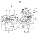
図2は、搬送チャンバ2と処理チャンバ1の構成の概要を示す。処理チャンバ1の構成は処理内容によって異なるが、真空で発光材料を蒸着しEL層を形成する真空蒸着チャンバ1buを例にとって説明する。図3は、そのとき搬送チャンバ2bと真空蒸着チャンバ1buの構成の模式図と動作説明図である。図2における搬送ロボット5は、全体を上下に移動可能(図3の矢印59参照)で、左右に旋回可能な3リンク構造のアーム57を有し、その先端には基板搬送用の櫛歯状ハンド58を上下二段に2本有する。1本ハンドの場合は、基板を次の工程に渡すための回転動作、前の工程から基板を受取るための回転動作、及びこれに付随するゲート弁の開閉動作が搬入出処理の間に必要だが、上下二段にすることによって、片方のハンドに搬入する基板を持たせ、基板を保持していない方のハンドで真空蒸着チャンバから基板の搬出動作をさせた後、連続して搬入動作を行なうことができる。
2本ハンドにするか1本ハンドにするかは要求される生産能力によって決める。以後の説明では、説明を簡単にするために1本ハンドで説明する。
FIG. 2 shows an outline of the configuration of the
Whether to use two hands or one hand depends on the required production capacity. In the following description, a single hand is used for the sake of simplicity.
一方、真空蒸着チャンバ1buは、大別して発光材料を蒸発させ基板6に蒸着させる蒸着部7と、基板6の必要な部分に蒸着させるアライメント部8と、及び搬送ロボット5と基板の受渡しを行い、蒸着部7へ基板6を移動させる処理受渡部9からなる。アライメント部8と処理受渡部9は右側Rラインと左側Lラインの2系統設ける。
On the other hand, the vacuum deposition chamber 1bu is broadly divided into a deposition unit 7 for evaporating a luminescent material and depositing it on the
処理受渡部9は、搬送ロボット5の櫛歯状ハンド58と干渉することなく基板6を受渡し可能とする櫛歯状ハンド91と、前記櫛歯状ハンド91上にあり基板6を固定して載置し、その基板6を旋回させて直立にし、アライメント部8に移動する基板旋回手段93を有する。前記固定する手段としては、真空中であることを考慮して静電吸着や機械的クランプ等の手段を用いる。
The
図4はこの基板旋回手段93を詳細に示し、基板旋回手段93に本発明の真空内配線・配管機構を適用した第1の実施例を示した図である。基板旋回手段93は、基板6を載置する載置台93Dと、蒸着時に基板6を冷却する冷却ジャケット93Jと、基板6、載置台93D及び冷却ジャケット93Jを一体となって回転させアライメント部8のシャドウマスク81に接触可能とする基板旋回駆動部93Bから構成されている。冷却ジャケット93Jには冷却水管43,44が敷設されている。また、基板旋回駆動部93Bは、大気側に設けられた旋回用モータ93Mと、旋回用モータ93Mにより歯車93H1、93H2を介して矢印Aの方向に旋回する中空の第1リンク41と、第1リンク41に第1リンクの中空部と連続した中空部を持つように固定され、前記冷却ジャケット93Jの側面部に沿うよう設けられた第2リンク42を有する。なお、第1リンクは真空蒸着チャンバ1buの側壁に設けられた真空シール部93Sに回転可能に支持されている。なお、旋回用モータ93Jは大気側にもうけられた制御装置60で制御される。
FIG. 4 shows the substrate turning means 93 in detail, and is a view showing a first embodiment in which the in-vacuum wiring / piping mechanism of the present invention is applied to the
本実施例における真空内配線・配管機構40は、上記第1リンク41及び第2リンク42から構成され、その中空部には、冷却ジャケット93Jに冷却水を流すために、供給用43と回収用44の冷却水配管が配設されている。各リンクは錆に強く十分な強度を持つ金属、例えばステンレス、アルミニウムで構成され、第1リンク41の中空部の駆動前モータ93M側は大気に開放されている。前記2本の冷却水配管は、一般的に大気中で使用されている柔軟性を有する材料で構成するか、金属性で構成し、リンク内で可撓部を有しないように第1リンク41及び第2リンク42で形成される形であるL字状に配管し、可撓部は大気側に設ける。後者を用いればより疲労損傷に少ない配管を構成できる。また、万が一冷却水が冷却水配管43、44から漏洩しても大気側に排水されように、前記真空蒸着チャンバ1buの側壁での接続部を冷却ジャケット93Jでの接続部より低くしている。
The in-vacuum wiring / piping mechanism 40 in the present embodiment is composed of the
本実施例の真空内配線・配管機構40の実施例によれば、一端を大気に開放し、多端を移動部に接続したリンク機構の中空部に配管を設け、前記リンク機構の回転部は真空シールされ、真空側から完全に遮断しているので、万が一、冷却水配管から漏水しても真空側に漏水することがなく、またリンク機構の中空部を真空にする必要もない。さらに、リンク機構をステンレスあるいはアルミニウムで構成しているのでアウトガスの発生もない。また、真空内配線・配管機構が基板旋回駆動部の一部を構成しているので全体としてシンプルな構成にできる。 According to the embodiment of the in-vacuum wiring / piping mechanism 40 of the present embodiment, a pipe is provided in the hollow portion of the link mechanism having one end opened to the atmosphere and the other end connected to the moving portion, and the rotating portion of the link mechanism is a vacuum Since it is sealed and completely shut off from the vacuum side, even if water leaks from the cooling water pipe, it does not leak to the vacuum side, and the hollow part of the link mechanism does not need to be evacuated. Further, since the link mechanism is made of stainless steel or aluminum, no outgas is generated. In addition, since the in-vacuum wiring / piping mechanism constitutes a part of the substrate turning drive unit, the overall structure can be simplified.
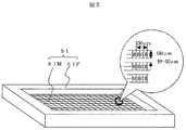
アライメント部8は、図5に示すマスク81M、フレーム81Fからなるシャドウマスク81と基板上のアライメントマーク84によって基板6とシャドウマスク81との位置合せをするアライメント駆動部83とを有する。
The
図6は、蒸着部7の構成を示し、真空内配線・配管機構の第2の実施例を示す図である。第6図(b)は、第6図(a)において矢印Bの方向から見た図である。蒸着部7は、蒸発部71をレール76上に沿って上下方向に移動させる上下駆動手段72、蒸発部71をレール75上に沿って左右のアライメント部間移動する左右駆動ベース74(図3参照)、真空内配線・配管機構50を有する。
FIG. 6 shows the configuration of the vapor deposition section 7 and is a diagram showing a second embodiment of the in-vacuum wiring / piping mechanism. FIG. 6 (b) is a view seen from the direction of arrow B in FIG. 6 (a). The vapor deposition unit 7 includes a
上下駆動手段72は、大気側に設けられた駆動モータ72M、同モータ72Mにより回転駆動され、シール部72Sに真空シールされた回転部72C、回転部72Cに固定され、回転部72Cに同期して回転するボールネジ72P、蒸発部71に固定され、ボールネジ72Pの回転により蒸発部71を上下させるナット72K及び前記上下時に蒸発部71のレール76上走行を案内する案内ガイド72Gから構成される。
The vertical drive means 72 is driven to rotate by a
蒸発部71は真空雰囲気にあり、複数個の蒸発源71a〜e(個数は必要により決定)を有し、各蒸発源71a〜eは内部に発光材料である蒸着材料71Z、前記蒸着材料を加熱するヒータ71H、蒸発温度を検知する温度センサ71Sを有し、前述した制御装置50は、温度センサ71Sの出力を見て安定した蒸発速度が得るようにヒータ71Hを制御する。図3の引出し図に示すように、蒸発部71には複数の蒸発源71a〜eの穴73がライン状に並んでおり、蒸着材料71Zはその穴からら蒸発する構造となっている。必要によっては、蒸着膜の特性を向上させるために添加剤も同時に加熱して蒸着する。この場合、蒸発源と一対若しくは複数の蒸発源と上下に平行に並べて蒸着する。
The
真空内配線・配管機構50は、一端が真空蒸着チャンバ1buの壁に回転可能で大気雰囲気に開放にされた状態で固定された中空の第1リンク51、一端が前記第1リンク51の他端に回転可能に接続され、他端が蒸着部71に回転可能に固定された中空の第2リンク52で構成されたリンク構造を有する。各回転部は後述する図7に示すような機構により真空シールされている。各リンクは錆に強く十分な強度を持つ金属、例えばステンスアルミニウムで構成され、中空のリンク内には、前述したヒータ71Hへの電圧線及び温度センサ71Sの信号線などの配線54が敷設されている。蒸着源71と第2リンクの接続部には、前記配線54を中継するフィードスルー55が設けられている。真空内配線・配管機構50は、蒸発部71に上下移動に伴い両リンクの接続部53が上下し、前記信号線、電圧線の配線を安定して目的位置に接続した状態を維持することが可能である。
The in-vacuum wiring / piping mechanism 50 has a hollow
図7は、真空シールの一例を示し、リンク51とリンク52との接続部53の真空シールの構成を示した図である。接続部53には、リンク51がリンク52に対してクロスローラベアリング53Pにより回転し、パッキン(Oリング)53P及びガスケット(Oリング)53Gで真空シールされた中空の回転部53Kある。この機構により、真空側と完全に遮断され、中空部に配線54を通すことが可能である。
FIG. 7 shows an example of the vacuum seal, and is a diagram showing the configuration of the vacuum seal of the
本実施例の真空内配線・配管機構50によれば、接続部が移動してもリンク機構でその移動を吸収し、回転部がシールされたステンレス製のリンクで真空領域から完全に遮断しているので、例え、配線からアウトガスが発生しても真空側にアウトガスが漏洩することがなく、またリンク機構内を真空にする必要ない。さらに、リンク機構をステンレスあるいはステンレスで構成しているのでアウトガスの発生もない。 According to the in-vacuum wiring / piping mechanism 50 of this embodiment, even if the connecting portion moves, the movement is absorbed by the link mechanism, and the rotating portion is completely shielded from the vacuum region by the sealed stainless steel link. Therefore, even if outgas is generated from the wiring, the outgas does not leak to the vacuum side, and the link mechanism does not need to be evacuated. Further, since the link mechanism is made of stainless steel or stainless steel, no outgas is generated.
図8は、このような構成によって処理チャンバ1の処理フローを示した図である。本実施形態での処理の基本的な考え方は、基板の蒸着面を上面にして搬送し、上面搬送された基板6を垂直にたてて、アライメント部8に搬送し、蒸着する。搬送時基板6の下面が蒸着面であるならば反転する必要があるが、上面が蒸着面であるので垂直にたてるだけでよい。
FIG. 8 is a diagram showing a processing flow of the
また、蒸着する工程と、処理チャンバ1への基板搬入出工程等のその他工程とは所要時間が略同じであり、本実施形態ではそれぞれ約1分である。そこで、本実施形態での処理の他の基本的な考え方は、一方のラインで蒸着して間に、他方のラインでは基板を搬入出し、位置合せをし、蒸着する準備を完了させることである。この処理を交互に行なうことによって、蒸発源中の材料が無駄に蒸発している時間を減少させることができる。
In addition, the time required for the vapor deposition process and the other processes such as the substrate carrying-in / out process for the
その処理フローを図3を参照しながら図7を用いて詳細に説明する。図3において基板6が存在するところは実線で示す。
The processing flow will be described in detail with reference to FIG. In FIG. 3, the place where the
まず、Rラインにおいて、基板6Rを搬入し、基板6Rを垂直に立ててアライメント部8Rに移動し、基板6とシャドウマスク81との位置合せを行なう(StepR1からStepR3)。このとき、垂直に立てて直ぐに位置合せを行なうために、蒸着面を上にして基板6を搬送する。位置合せは、図3の引出し図に示すように、CCDカメラ86で撮像し、基板6に設けられたアライメントマーク84がマスク81M設けられた窓85の中心にくるように、シャドウマスク81Rを前記アライメント駆動部83で制御することによって行なう。本蒸着が赤(R)を発光させる材料であるならば、図4に示すようにマスク81MのRに対応する部分に窓があいており、その部分が蒸着されることになる。その窓の大きさは色によって異なるが平均して幅50μm、高さ150μm程度である。マスク81Mの厚さは40μmであり、今後さらに薄くなる傾向がある。
First, in the R line, the substrate 6R is carried in, the substrate 6R is vertically set up and moved to the alignment unit 8R, and the
位置合せが終了したら、蒸発部71をRライン側に移動させ(StepR4)、その後ライン状の蒸発部71を上又は下に移動させて蒸着する(StepR5)。Rライン蒸着中に、LラインではRラインの同様にStepL1からStepL3の処理を行なう。すなわち、他の基板6Lを搬入し、当該基板6Lを垂直に立ててアライメント部8Lに移動し、シャドウマスク81Lとの位置合せを行なう。Rラインの基板6Rの蒸着を完了すると、蒸発部71はLラインに移動し(StepL4)、Lラインにある基板6Lを蒸着する(StepL5)。このとき蒸発部71がRラインの蒸着領域から完全に出る前に、基板6Rがアライメント部8Rから離れると、不必要に蒸着される可能性があるので、完全に出た後に、基板6Rの処理チャンバ1からの搬出動作を開始し、その後新たな基板6Rの準備に入る。前記不必要な蒸着を避けるためにラインの間に仕切り板11を設ける。なお、図3は、StepR4及びStepL1の状態を示している。即ち、Rラインでは蒸着を開始し、Lラインでは真空蒸着チャンバ1buに基板を搬入した状態である。
When the alignment is completed, the
その後、上記フローを連続して行なうことにより、本実施形態によれば、蒸発部7の移動時間を除いて無駄に蒸着材料を使用することなく蒸着することができる。前述したように必要な蒸着時間とその他処理時間は約1分であり、蒸発部71の移動時間を5秒とすれば、従来は1分の無駄な蒸着時間が本実施形態では5秒に短縮できる。
また、上記本実施形態によれば、図5に示すように真空蒸着チャンバ1buの処理基板1枚の処理サイクルは実質的に蒸着時間+蒸発部71の移動時間となり、生産性を向上させることができる。前述の条件で処理時間を評価すれば、従来の2分に対し、本発明では1分5秒となり、チャンバひとつあたりの生産性を約2倍に向上できる。
Thereafter, by continuously performing the above flow, according to the present embodiment, it is possible to perform vapor deposition without wasteful use of the vapor deposition material except for the moving time of the evaporation unit 7. As described above, the necessary vapor deposition time and other processing time are about 1 minute. If the moving time of the
Further, according to the present embodiment, as shown in FIG. 5, the processing cycle of one processing substrate in the vacuum deposition chamber 1bu is substantially the deposition time + the moving time of the
上記実施形態では、一つの処理装置の中に一つの蒸着部7に対してアライメント部8L、処理受渡部9からなる2系統の処理ラインを設けた。例えば、蒸着時間30秒で、その他の処理時間が1分ならば、一つの処理装置の中に一つの蒸着部7に対して処理ラインを3系統設けても同様に大きな効果を得ることができる。
In the above embodiment, two processing lines including the alignment unit 8L and the
以上の説明した実施形態によれば、本実施例で示した真空内配線・配管機構を使用することによって、信頼性の高い有機ELデバイス製造装置を提供することができる。 According to the embodiment described above, a highly reliable organic EL device manufacturing apparatus can be provided by using the in-vacuum wiring / piping mechanism shown in this example.
上記の実施形態の説明では、2箇所における真空内配線・配管機構を説明した。その他にも適用できる箇所があり、本発明を適用可能である。例えば、図3において隣接するアライメント部に蒸着源を移動させるには、壁と第1リンクとの間に第1リンクと第2リンクからなる同様な構成のリンク機構を設ければよい。あるいは、蒸着速度を検出するために水晶モニター(図示せず)がある。水晶モニターは蒸発源71の移動に伴い移動する必要があり、かつ恒温に保つ必要がある。その場合、同様なリンク構成で水などの流体を供給・回収することができる。
In the description of the above embodiment, the in-vacuum wiring / piping mechanism at two locations has been described. There are other places where the present invention can be applied, and the present invention is applicable. For example, in order to move the vapor deposition source to the adjacent alignment unit in FIG. 3, a link mechanism having a similar configuration including a first link and a second link may be provided between the wall and the first link. Alternatively, there is a crystal monitor (not shown) to detect the deposition rate. The crystal monitor needs to move as the
上記の実施形態は全て基板6の蒸着面を上にして搬送する場合について説明した。その他の基板の搬送方法としては、蒸着面を下にして搬送する方法、基板をケース等に入れて立てて搬送する方法がある。
In the above-described embodiments, the case where the
しかしながら、上記の真空内配線・配管機構の基本的な考え方は、搬送方法には関係ないので、搬送方法の如何に関わらず本発明を適用できる。 However, since the basic concept of the above-described in-vacuum wiring / piping mechanism is not related to the transport method, the present invention can be applied regardless of the transport method.
また、上記説明では有機ELデバイスを例に説明したが、有機ELデバイスと同じ背景にある蒸着処理をする成膜装置および成膜方法にも適用できる。 In the above description, the organic EL device has been described as an example. However, the present invention can also be applied to a film forming apparatus and a film forming method that perform vapor deposition processing in the same background as the organic EL device.
1:処理チャンバ 1bu:真空蒸着チャンバ
2:搬送チャンバ 3:ロードクラスタ
4:受渡室 5:搬送ロボット
6:基板 7:蒸着部
8:アライメント部 9:処理受渡部
10:ゲート弁 11:仕切り板
31:ロード室 40,50:真空内配線・配管機構
60:制御装置 41、42、51,52:リンク
43,44:冷却水配管 54:配線
71:蒸発源 100:有機ELデバイスの製造装置
A〜D:クラスタ。
1: Processing chamber 1bu: Vacuum deposition chamber 2: Transfer chamber 3: Load cluster 4: Delivery chamber 5: Transfer robot 6: Substrate 7: Deposition unit 8: Alignment unit 9: Processing transfer unit 10: Gate valve 11: Partition plate 31 : Load chamber 40, 50: In-vacuum wiring / piping mechanism 60:
Claims (5)
該第2の移動部を旋回させて直立し、蒸着位置に正対させる基板旋回駆動部と、備え
該基板旋回駆動部は、大気側に設けられた駆動源により旋回する第1のリンクと、一端を該第1リンクに、他端を前記第2の移動部に固定された第2リンクとを備え、
前記第1リンク及び該第2リンクを第2の中空のリンクで構成し、前記第2の中空のリンク内に前記第2の移動部への配線または流体を流す配管のうち少なくとも流体を流す前記配管を敷設し、前記第1のリンクの前記大気側を大気に開放し、前記第2リンクの他端側を前記第2の移動部に接続した第2の真空内配線・配管機構を備え、
かつ前記第2の中空のリンクの可動部、前記第2の移動部への接続部及び大気への接続部が真空シールされていると共に、前記第2の中空のリンクは金属であり、
前記配管は、前記基板を冷却する前記移動体上の冷却部に流体を供給・回収する配管であることを特徴とする成膜装置。 A second moving part for placing and moving a substrate to be deposited in a vacuum chamber;
A substrate turning drive unit that turns the second moving unit upright and directly faces the deposition position, and the substrate turning drive unit includes a first link that is turned by a drive source provided on the atmosphere side; One end of the second link fixed to the first link and the other end fixed to the second moving unit ;
Wherein said first link and the second link is constituted by a second hollow links, passing at least a fluid of the pipe to flow lines or fluid to the second mobile unit to the second hollow link A second in- vacuum wiring / piping mechanism in which piping is laid, the atmosphere side of the first link is opened to the atmosphere, and the other end side of the second link is connected to the second moving part;
And while the movable part of the second hollow link, the connection part to the second moving part and the connection part to the atmosphere are vacuum-sealed, the second hollow link is a metal,
The film forming apparatus , wherein the pipe is a pipe that supplies and recovers a fluid to a cooling unit on the moving body that cools the substrate .
第1の中空のリンクで構成し、該第1の中空のリンク内に前記第1の移動部への配線または流体を流す配管のうち少なくとも一方を敷設し、一端を大気に開放し、他端を前記第1の移動部に接続した第1の真空内配線・配管機構を備え、
かつ前記第1の中空のリンクの可動部、前記第1の移動部への接続部及び大気への接続部が真空シールされていると共に、前記第1の中空のリンクは金属であることを特徴とする成膜装置。 A first moving unit for moving an evaporation source for evaporating the deposition material in the vacuum chamber;
Constituted by a first hollow link, flow lines or fluid into the inside hollow link of the first first moving part laying at least one of the pipe, open at one end to the atmosphere, the other end A first in- vacuum wiring / piping mechanism connected to the first moving part,
The movable part of the first hollow link, the connection part to the first moving part and the connection part to the atmosphere are vacuum-sealed, and the first hollow link is made of metal. A film forming apparatus.
前記金属はステンレスまたはアルミニウムであること特徴とする成膜装置。 In the film-forming apparatus of Claim 1 or 2,
The film forming apparatus, wherein the metal is stainless steel or aluminum.
前記第1の移動部は、前記基板への蒸着速度を検出するセンサを有することを特徴とする成膜装置。 In the film-forming apparatus of Claim 2,
Said first moving unit, the film forming apparatus according to claim and Turkey to have a sensor which detects the deposition rate to the substrate.
Priority Applications (1)
| Application Number | Priority Date | Filing Date | Title |
|---|---|---|---|
| JP2008246503A JP5231917B2 (en) | 2008-09-25 | 2008-09-25 | Deposition equipment |
Applications Claiming Priority (1)
| Application Number | Priority Date | Filing Date | Title |
|---|---|---|---|
| JP2008246503A JP5231917B2 (en) | 2008-09-25 | 2008-09-25 | Deposition equipment |
Publications (3)
| Publication Number | Publication Date |
|---|---|
| JP2010080230A JP2010080230A (en) | 2010-04-08 |
| JP2010080230A5 JP2010080230A5 (en) | 2011-02-03 |
| JP5231917B2 true JP5231917B2 (en) | 2013-07-10 |
Family
ID=42210432
Family Applications (1)
| Application Number | Title | Priority Date | Filing Date |
|---|---|---|---|
| JP2008246503A Expired - Fee Related JP5231917B2 (en) | 2008-09-25 | 2008-09-25 | Deposition equipment |
Country Status (1)
| Country | Link |
|---|---|
| JP (1) | JP5231917B2 (en) |
Families Citing this family (6)
| Publication number | Priority date | Publication date | Assignee | Title |
|---|---|---|---|---|
| JP5476227B2 (en) * | 2010-06-29 | 2014-04-23 | 株式会社日立ハイテクノロジーズ | Film forming apparatus and film forming method |
| CN105555996B (en) * | 2013-09-26 | 2017-03-22 | 株式会社爱发科 | Substrate processing device and film forming device |
| KR101553626B1 (en) * | 2013-12-19 | 2015-09-16 | 주식회사 에스에프에이 | Apparatus for turning glass |
| KR102215483B1 (en) * | 2018-04-03 | 2021-02-10 | 어플라이드 머티어리얼스, 인코포레이티드 | Apparatus for handling carrier in vacuum chamber, vacuum deposition system, and method of handling carrier in vacuum chamber |
| CN110557953B (en) * | 2018-04-03 | 2021-10-29 | 应用材料公司 | Device and vacuum system for alignment of a carrier in a vacuum chamber and method for aligning a carrier |
| JP6627181B1 (en) * | 2018-07-31 | 2020-01-08 | キヤノントッキ株式会社 | Evaporation source and evaporation equipment |
Family Cites Families (7)
| Publication number | Priority date | Publication date | Assignee | Title |
|---|---|---|---|---|
| JP4286496B2 (en) * | 2002-07-04 | 2009-07-01 | 株式会社半導体エネルギー研究所 | Vapor deposition apparatus and thin film manufacturing method |
| JP3965479B2 (en) * | 2003-07-28 | 2007-08-29 | 株式会社エフ・ティ・エスコーポレーション | Box type opposed target type sputtering apparatus and compound thin film manufacturing method |
| JP4345057B2 (en) * | 2004-04-19 | 2009-10-14 | 日本精工株式会社 | Positioning device |
| JP2006241489A (en) * | 2005-03-01 | 2006-09-14 | Canon Inc | Positioning device, and apparatus for manufacturing organic electroluminescence panel |
| JP2007332458A (en) * | 2006-05-18 | 2007-12-27 | Sony Corp | Vapor deposition apparatus, and vapor deposition source, and display device manufacturing method |
| KR20090130559A (en) * | 2008-06-16 | 2009-12-24 | 삼성모바일디스플레이주식회사 | Transfer apparatus and organic deposition device with the same |
| JP2010040956A (en) * | 2008-08-08 | 2010-02-18 | Tokyo Electron Ltd | Substrate processing apparatus |
-
2008
- 2008-09-25 JP JP2008246503A patent/JP5231917B2/en not_active Expired - Fee Related
Also Published As
| Publication number | Publication date |
|---|---|
| JP2010080230A (en) | 2010-04-08 |
Similar Documents
| Publication | Publication Date | Title |
|---|---|---|
| JP5231917B2 (en) | Deposition equipment | |
| KR102151616B1 (en) | In-line deposition system and method for operating an evaporation source for organic material | |
| KR101281909B1 (en) | Thin film deposition device | |
| JP5074429B2 (en) | Deposition equipment | |
| JP5074368B2 (en) | Deposition equipment | |
| JP5167103B2 (en) | Deposition equipment | |
| JP2010077487A (en) | Apparatus for manufacturing organic el device and method for manufacturing the same, and film deposition apparatus and film deposition method | |
| KR101119790B1 (en) | Manufacturing device of organic el device and method of manufacturing organic el device and layer forming device and layer forming method | |
| JP2008088483A (en) | Vapor deposition apparatus and method for operating the same | |
| JP2011026625A (en) | Film deposition apparatus and film deposition method | |
| JP2013093279A (en) | Organic el device manufacturing apparatus | |
| JP5203584B2 (en) | Film forming apparatus, film forming system, and film forming method | |
| JP4768001B2 (en) | ORGANIC EL DEVICE MANUFACTURING APPARATUS, ITS MANUFACTURING METHOD, FILM-FORMING APPARATUS, AND FILM-FORMING METHOD | |
| JP5277015B2 (en) | Organic EL device manufacturing apparatus, film forming apparatus, and shadow mask exchange apparatus | |
| JP2008038224A (en) | Film deposition apparatus, film deposition system, and film deposition method | |
| JP2010080228A (en) | Organic el device manufacturing device, film forming device, and device and method for replacing shadow mask | |
| KR101168150B1 (en) | Thin layer deposition apparatus | |
| JP5476227B2 (en) | Film forming apparatus and film forming method | |
| JP7304261B2 (en) | Film forming apparatus, film forming method, and electronic device manufacturing method | |
| JP4951712B2 (en) | ORGANIC EL DEVICE MANUFACTURING APPARATUS, ITS MANUFACTURING METHOD, FILM-FORMING APPARATUS, AND FILM-FORMING METHOD | |
| JP2013151760A (en) | Method for replacing shadow mask | |
| JP2013110114A (en) | Apparatus for manufacturing organic el device and angle correction mechanism | |
| KR20120022592A (en) | Transfer apparatus and substrate and substrate processing apparatus | |
| JP2013249545A (en) | Film forming apparatus |
Legal Events
| Date | Code | Title | Description |
|---|---|---|---|
| A521 | Request for written amendment filed |
Free format text: JAPANESE INTERMEDIATE CODE: A523 Effective date: 20101214 |
|
| A621 | Written request for application examination |
Free format text: JAPANESE INTERMEDIATE CODE: A621 Effective date: 20110126 |
|
| A977 | Report on retrieval |
Free format text: JAPANESE INTERMEDIATE CODE: A971007 Effective date: 20120302 |
|
| A131 | Notification of reasons for refusal |
Free format text: JAPANESE INTERMEDIATE CODE: A131 Effective date: 20120321 |
|
| A521 | Request for written amendment filed |
Free format text: JAPANESE INTERMEDIATE CODE: A523 Effective date: 20120517 |
|
| A131 | Notification of reasons for refusal |
Free format text: JAPANESE INTERMEDIATE CODE: A131 Effective date: 20120703 |
|
| A521 | Request for written amendment filed |
Free format text: JAPANESE INTERMEDIATE CODE: A523 Effective date: 20120830 |
|
| TRDD | Decision of grant or rejection written | ||
| A01 | Written decision to grant a patent or to grant a registration (utility model) |
Free format text: JAPANESE INTERMEDIATE CODE: A01 Effective date: 20130305 |
|
| A61 | First payment of annual fees (during grant procedure) |
Free format text: JAPANESE INTERMEDIATE CODE: A61 Effective date: 20130322 |
|
| FPAY | Renewal fee payment (event date is renewal date of database) |
Free format text: PAYMENT UNTIL: 20160329 Year of fee payment: 3 |
|
| R150 | Certificate of patent or registration of utility model |
Free format text: JAPANESE INTERMEDIATE CODE: R150 |
|
| LAPS | Cancellation because of no payment of annual fees |