JP5228564B2 - Body front structure - Google Patents
Body front structure Download PDFInfo
- Publication number
- JP5228564B2 JP5228564B2 JP2008078871A JP2008078871A JP5228564B2 JP 5228564 B2 JP5228564 B2 JP 5228564B2 JP 2008078871 A JP2008078871 A JP 2008078871A JP 2008078871 A JP2008078871 A JP 2008078871A JP 5228564 B2 JP5228564 B2 JP 5228564B2
- Authority
- JP
- Japan
- Prior art keywords
- transmission
- engine
- vehicle body
- power unit
- flange portion
- Prior art date
- Legal status (The legal status is an assumption and is not a legal conclusion. Google has not performed a legal analysis and makes no representation as to the accuracy of the status listed.)
- Active
Links
Images
Landscapes
- Body Structure For Vehicles (AREA)
Description
本発明は、横置き式のパワーユニットを搭載した車両の車体前部構造に関する。 The present invention relates to a front body structure of a vehicle on which a horizontally mounted power unit is mounted.
多くの車種はエンジンとトランスミッションとを一体に結合したパワーユニットを車体前部のエンジンルーム内に搭載している。特に、F・F車ではトランスミッションにディファレンシャルギアを一体化したトランスアクスルを構成し、このトランスアクスルをエンジンと一体化したパワーユニットを横置きで搭載するようになっている。 Many vehicle models have a power unit that combines the engine and transmission in the engine room at the front of the vehicle. In particular, F and F cars have a transaxle that integrates a differential gear into the transmission, and a power unit that integrates the transaxle with the engine is installed horizontally.
このような横置き式のパワーユニットは、適宜な複数箇所がエンジンマウントを介して車体側に支持される。例えば、パワーユニットは、少なくとも車幅方向両端部にエンジンマウントを取り付けて、それらエンジンマウントを左右一対のサイドメンバに載置するようになっている(例えば、特許文献1参照)。
しかしながら、かかる従来の車体前部構造では、局部的に衝突荷重が入力する衝突(この局部的な衝突をポール衝突と呼ぶことにする)の場合、その時の衝突荷重はフロントバンパーのバンパーレインフォースやラジエータを変形させつつエンジンルーム内に進入してパワーユニットを後方に移動させる。このとき、ポール衝突がパワーユニットのトランスミッション配置側に片寄ったオフセット衝突の場合、トランスミッション側のエンジンマウントを破壊しつつ、エンジン側のエンジンマウントを中心としてトランスミッションを車両後方に旋回させる。すると、そのトランスミッションは、ダッシュパネルを変形しつつ車室側に移動する。 However, in such a conventional vehicle body front structure, in the case of a collision in which a collision load is input locally (this local collision will be referred to as a pole collision), the collision load at that time is the bumper reinforcement of the front bumper or the radiator. The power unit is moved backward by entering the engine room while deforming. At this time, in the case of an offset collision in which the pole collision is shifted to the transmission arrangement side of the power unit, the transmission is turned backward with respect to the engine mount on the engine side while the engine mount on the engine side is broken. Then, the transmission moves to the passenger compartment side while deforming the dash panel.
このため、ポール衝突がパワーユニットに及ぶのを抑制しようとすると、バンパーレインフォースを補強したり、サイドメンバやその下側に結合するサブフレームを補強したりする必要があり、車体重量の増加が余儀なくされることになる。 For this reason, if it is attempted to suppress the pole collision from reaching the power unit, it is necessary to reinforce the bumper reinforcement or to reinforce the side members and the subframes coupled to the side members, which inevitably increases the vehicle weight. Will be.
そこで、本発明は、車体重量の大幅な増加を来すことなく、パワーユニットのトランスミッション側の後方移動を効果的に抑制することができる車体前部構造を提供するものである。 Therefore, the present invention provides a vehicle body front part structure that can effectively suppress the rearward movement of the power unit on the transmission side without significantly increasing the vehicle body weight.
本発明は、エンジンとトランスミッションとを一体に結合した横置き式のパワーユニットを、車体前部における左右両側の一対のサイドメンバに跨って載置し、この一対のサイドメンバのうちトランスミッションが配置される側のサイドメンバに、該トランスミッションの後側端部に係止する後退規制部材を一体に設け、前記後退規制部材は、そのサイドメンバから突出する先端部を前方に屈曲させて鉤部を形成するとともに、その鉤部を、トランスミッションのミッションハウジングのフランジ部とハウジングカバーのフランジ部とを有する結合部にエンジンの配置側から係合させたことを最も主要な特徴とする。 In the present invention, a horizontally mounted power unit in which an engine and a transmission are integrally coupled is placed across a pair of left and right side members in a front part of a vehicle body, and the transmission is disposed among the pair of side members. A retreat restricting member that is engaged with the rear end of the transmission is integrally provided on the side member on the side, and the retreat restricting member bends the front end protruding from the side member forward to form a flange. At the same time, the main feature is that the flange portion is engaged with a connecting portion having a flange portion of the transmission housing of the transmission and a flange portion of the housing cover from the arrangement side of the engine .
本発明によれば、パワーユニットのトランスミッションの配置側に片寄って局部的な前
面衝突が発生し、トランスミッションが後方に移動しようとした場合に、サイドメンバに
設けた後退規制部材がトランスミッションの後側端部に係止する。これにより、トランス
ミッションの後方移動力は後退規制部材を介してサイドメンバで支持することができ、ト
ランスミッションの後方移動を効率良く抑制することができる。従って、後退規制部材を
設けるという簡単な構成により、車体重量の大幅な増加を来すことなくトランスミッショ
ンが車室側へ移動するのを抑制できる。
また、後退規制部材は、そのサイドメンバから突出する先端部を前方に屈曲させて鉤部を形成し、その鉤部を、トランスミッションのミッションハウジングとハウジングカバーとの結合部であるフランジ部にエンジンの配置側から係合させてある。これにより、トランスミッションが後方移動した際に、フランジ部が後退規制部材の鉤部に確実に係合するため、トランスミッションの後退をより確実に抑制できる。
According to the present invention, when a frontal frontal collision occurs on the transmission side of the power unit and the transmission is about to move rearward, the reverse regulating member provided on the side member is the rear end of the transmission. Lock to. Thereby, the rearward movement force of the transmission can be supported by the side member via the reverse regulating member, and the rearward movement of the transmission can be efficiently suppressed. Therefore, with the simple configuration of providing the reverse movement restricting member, it is possible to suppress the transmission from moving toward the passenger compartment without significantly increasing the vehicle body weight.
Further, the retraction restricting member bends the front end portion protruding from the side member forward to form a flange portion, and the flange portion is connected to a flange portion that is a connecting portion between the transmission housing and the housing cover of the engine. It is engaged from the arrangement side. Thereby, when the transmission moves rearward, the flange portion reliably engages with the flange portion of the retraction restricting member, so that the retraction of the transmission can be more reliably suppressed.
以下、本発明の実施形態を図面と共に詳述する。 Hereinafter, embodiments of the present invention will be described in detail with reference to the drawings.
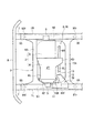
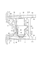
図1および図2は本発明にかかる車体前部構造の一実施形態を示し、図1はパワーユニットを搭載した車体前部の骨格構造を示す平面図、図2はポール衝突時の車体前部の骨格構造を示す平面図である。 1 and 2 show an embodiment of a vehicle body front structure according to the present invention. FIG. 1 is a plan view showing a skeleton structure of a vehicle body front portion on which a power unit is mounted. FIG. It is a top view which shows skeletal structure.
図1に示すように、本実施形態の車体前部構造は、車体前部に設けたエンジンルームE/Rの車幅方向両側(図1中で上下両側)には、車両前後方向(図1中で左右方向)に延在する左右一対のサイドメンバ1L、1Rを配設してあり、これら一対のサイドメンバ1L、1Rが車体前部の骨格部材となっている。
As shown in FIG. 1, the vehicle body front structure of the present embodiment has a vehicle front-rear direction (FIG. 1) on both sides in the vehicle width direction (upper and lower sides in FIG. 1) of the engine room E / R provided at the front of the vehicle body. A pair of left and
そして、一対のサイドメンバ1L、1Rに跨ってパワーユニット2を搭載してある。パワーユニット2は、エンジン3とトランスミッション4とを結合して構成し、そのパワーユニット2を横置き状態でサイドメンバ1L、1Rに搭載してある。尚、本実施形態ではエンジン3を右舷側、トランスミッション4を左舷側に配置してある。また、5はエンジンマウントである。
And the
トランスミッション4は、ディファレンシャルギア4Dを一体化したトランスアクスル4Tとして構成してあり、後方に突出したディファレンシャルギア4Dの両側から図示省略した左右の前輪を駆動する左右のドライブシャフト6L、6Rが突出する。
The transmission 4 is configured as a
一対のサイドメンバ1L、1Rの前端にはそれぞれバンパーステイ7を結合し、それら左右一対のバンパーステイ7に跨ってバンパーレインフォース8を取り付けてある。
Bumper stays 7 are respectively coupled to the front ends of the pair of
また、左右一対のサイドメンバ1L、1Rの下側に跨って、パワーユニット2よりも前方に一部が位置する下部連結部材としてのサブフレーム9を結合してある。サブフレーム9は、サイドメンバ1L、1Rに沿った左右フレーム91、92と、前後フレーム93、94と、によって略井桁状に形成してあり、前フレーム93がパワーユニット2よりも前方に位置している。そして、左右フレーム91、92の前端部91f、92fおよび後端部91r、92rを、サイドメンバ1L、1Rの前部および後部にブッシュなどの連結部材95を介して結合してある。サブフレーム9には図示省略した前輪のナックルスピンドルやサスペンションアームなどを取り付けてある。
In addition, a
ここで、本発明にあっては、一対のサイドメンバ1L、1Rのうちトランスミッション4が配置される側、つまり、本実施形態では左舷のサイドメンバ1Lに、トランスミッション4の後側端部に係止する後退規制部材10を一体に設けてある。
Here, in the present invention, of the pair of
後退規制部材10は、サイドメンバ1Lに結合する取付部11と、この取付部11からサイドメンバ1Lに対して略直角方向内側に突出する係止部12と、によって形成してある。取付部11は、サイドメンバ1Lの上・下側面および内側面に沿った断面略コ字状に形成してあり、その取付部11をサイドメンバ1Lの内側から嵌合してボルト・ナットやスポット溶接などの手段によって強固に結合してある。
The
また、後退規制部材10は、そのサイドメンバ1Lから突出する先端部、つまり、係止部12の先端部を前方に屈曲させて鉤部13を形成してある。そして、その鉤部13を、トランスミッション4のミッションハウジング41とハウジングカバー42との結合部であるフランジ部41F、42Fに、エンジン3の配置側から係合させてある。
Further, the
即ち、フランジ部41F、42Fは、ミッションハウジング41およびハウジングカバー42の結合端部外周からリング状に突出しており、それらフランジ部41F、42Fのエンジン3の配置側に後退規制部材10の鉤部13を確実に係合できるようになっている。
That is, the
以上の構成により本実施形態の車体前部構造によれば、パワーユニット2のトランスミッション4の配置側に片寄ってポール衝突した場合、例えば、図2に示すように、電柱や街灯支柱などの柱状固定物Pにオフセット衝突した場合、バンパーレインフォース8およびサブフレーム9の前フレーム93を変形しつつ、衝突荷重Fがトランスミッション4に入力する。
According to the vehicle body front structure of the present embodiment having the above-described configuration, when a pole collision occurs in the
すると、トランスミッション4は、これに一体に結合したエンジン3の端部のエンジンマウント5を中心として後方に移動しようとするが、このとき、サイドメンバ1Lに設けた後退規制部材10の係止部12がトランスミッション4の後側端部、つまり、フランジ部41F、42Fの後側に係止する。
Then, the transmission 4 tries to move backward about the
これにより、トランスミッション4の後方移動力は後退規制部材10を介してサイドメンバ1Lで支持することができ、トランスミッション4の後方移動を効率良く抑制することができる。
Thereby, the rearward movement force of the transmission 4 can be supported by the
従って、本実施形態の車体前部構造では後退規制部材10を設けるという簡単な構成により、車体重量の大幅な増加を来すことなくトランスミッション4が車室側に移動するのを抑制できる。
Therefore, in the vehicle body front part structure of the present embodiment, the simple configuration of providing the
ところで、このように後退規制部材10によってトランスミッション4の後退を抑制できるのであるが、パワーユニット2に入力した衝突荷重Fは、上述した後退規制部材10およびエンジン3側のエンジンマウント5を介して左右のサイドメンバ1L、1Rに分散させることができる。
By the way, although the reverse movement of the transmission 4 can be suppressed by the reverse
また、後退規制部材10は、そのサイドメンバ1Lから突出する先端部(係止部12)を前方に屈曲させて鉤部13を形成し、その鉤部13を、トランスミッション4のミッションハウジング41とハウジングカバー42との結合部であるフランジ部41F、42Fにエンジン3の配置側から係合させてある。これにより、トランスミッション4が後方移動した際に、フランジ部41F、42Fが後退規制部材10の鉤部13に確実に係合するため、トランスミッション4の後退をより確実に抑制できる。
Further, the
更に、左右一対のサイドメンバ1L、1Rの下側に跨ってサブフレーム9を結合し、図2に示すように、パワーユニット2よりも前方にサブフレーム9の前フレーム93が位置しているため、柱状固定物Pがトランスミッション4に干渉する前に前フレーム93が変形することになる。このように、前フレーム93が変形すると、左右一対のサイドメンバ1L、1Rの前部は、図2中矢印Xで示すように互いに近接する。これにより、ポール衝突時には後退規制部材10が車両中心側に変位することになり、その後退規制部材10の係止部12をより短くした場合にもトランスミッション4と係合でき、更なる軽量化を達成することができる。
Furthermore, the
1L、1R サイドメンバ
2 パワーユニット
3 エンジン
4 トランスミッション
41 トランスミッションのミッションハウジング
42 トランスミッションのハウジングカバー
41F、42F フランジ部(結合部)
9 サブフレーム(下部連結部材)
10 後退規制部材
13 後退規制部材の鉤部
1L,
9 Subframe (lower connecting member)
10
Claims (2)
前記一対のサイドメンバのうち前記トランスミッションが配置される側のサイドメンバに、該トランスミッションの後側端部に係止する後退規制部材を一体に設け、
前記後退規制部材は、そのサイドメンバから突出する先端部を前方に屈曲させて鉤部を形成するとともに、その鉤部を、トランスミッションのミッションハウジングのフランジ部とハウジングカバーのフランジ部とを有する結合部にエンジンの配置側から係合させたことを特徴とする車体前部構造。 In the vehicle body front structure in which the horizontal power unit in which the engine and the transmission are integrally coupled is placed across a pair of left and right side members disposed on the left and right sides of the vehicle body front part,
The side member on the side where the transmission is arranged among the pair of side members is integrally provided with a retraction regulating member that is locked to the rear end of the transmission ,
The retraction restricting member bends a front end portion protruding from the side member forward to form a flange portion, and the flange portion includes a flange portion of a transmission housing and a flange portion of a housing cover. A vehicle body front structure characterized by being engaged with the engine from the side where the engine is disposed .
Priority Applications (1)
| Application Number | Priority Date | Filing Date | Title |
|---|---|---|---|
| JP2008078871A JP5228564B2 (en) | 2008-03-25 | 2008-03-25 | Body front structure |
Applications Claiming Priority (1)
| Application Number | Priority Date | Filing Date | Title |
|---|---|---|---|
| JP2008078871A JP5228564B2 (en) | 2008-03-25 | 2008-03-25 | Body front structure |
Publications (2)
| Publication Number | Publication Date |
|---|---|
| JP2009234279A JP2009234279A (en) | 2009-10-15 |
| JP5228564B2 true JP5228564B2 (en) | 2013-07-03 |
Family
ID=41248799
Family Applications (1)
| Application Number | Title | Priority Date | Filing Date |
|---|---|---|---|
| JP2008078871A Active JP5228564B2 (en) | 2008-03-25 | 2008-03-25 | Body front structure |
Country Status (1)
| Country | Link |
|---|---|
| JP (1) | JP5228564B2 (en) |
Families Citing this family (2)
| Publication number | Priority date | Publication date | Assignee | Title |
|---|---|---|---|---|
| JP2016088264A (en) | 2014-11-04 | 2016-05-23 | トヨタ自動車株式会社 | Vehicle structure |
| FR3122125A1 (en) * | 2021-04-26 | 2022-10-28 | Psa Automobiles Sa | VEHICLE WITH REVERSE DRIVE MACHINE |
Family Cites Families (3)
| Publication number | Priority date | Publication date | Assignee | Title |
|---|---|---|---|---|
| JP3921969B2 (en) * | 2001-07-13 | 2007-05-30 | 日産自動車株式会社 | Front body structure of automobile |
| JP2004090828A (en) * | 2002-09-02 | 2004-03-25 | Honda Motor Co Ltd | Vehicle body front structure |
| JP4794985B2 (en) * | 2005-11-07 | 2011-10-19 | 富士重工業株式会社 | Vehicle frame structure |
-
2008
- 2008-03-25 JP JP2008078871A patent/JP5228564B2/en active Active
Also Published As
| Publication number | Publication date |
|---|---|
| JP2009234279A (en) | 2009-10-15 |
Similar Documents
| Publication | Publication Date | Title |
|---|---|---|
| CN104203724B (en) | The structure of front auxiliary frame of automobile | |
| JP5887432B2 (en) | Body front structure | |
| EP2768719B1 (en) | Rear-wheel drive, plug-in hybrid electric vehicle modular subframe assembly and method | |
| JP6624526B2 (en) | Body structure | |
| JP5549334B2 (en) | Rear structure of electric vehicle body | |
| US10086881B2 (en) | Front vehicle body structure | |
| US8857902B2 (en) | Front vehicle body structure | |
| JP4298940B2 (en) | Car body rear structure | |
| JP6020944B2 (en) | Auto body structure | |
| US20170120953A1 (en) | Subframe for vehicle | |
| JP6511885B2 (en) | Automotive front structure | |
| CN104010922A (en) | Front sub-frame structure for automobiles | |
| JP2006193118A (en) | Body front structure | |
| JP5867115B2 (en) | Lower body structure of the vehicle | |
| JP6299701B2 (en) | Vehicle lower structure | |
| JP6600228B2 (en) | Subframe for vehicle | |
| JP2016196207A (en) | Rear vehicle body structure of vehicle | |
| US20240253701A1 (en) | Vehicle body frame structure | |
| JP5228564B2 (en) | Body front structure | |
| JP2009226971A (en) | Lower vehicle body structure | |
| JP4923406B2 (en) | Body front structure | |
| JP2012071783A (en) | Vehicle body front structure of motor vehicle | |
| JP5832508B2 (en) | Body frame structure | |
| JP2004284576A (en) | Suspension support device | |
| JP2016055870A (en) | Vehicle-body front structure of vehicle |
Legal Events
| Date | Code | Title | Description |
|---|---|---|---|
| A621 | Written request for application examination |
Free format text: JAPANESE INTERMEDIATE CODE: A621 Effective date: 20110224 |
|
| A977 | Report on retrieval |
Free format text: JAPANESE INTERMEDIATE CODE: A971007 Effective date: 20120705 |
|
| A131 | Notification of reasons for refusal |
Effective date: 20120710 Free format text: JAPANESE INTERMEDIATE CODE: A131 |
|
| A521 | Written amendment |
Free format text: JAPANESE INTERMEDIATE CODE: A523 Effective date: 20120831 |
|
| TRDD | Decision of grant or rejection written | ||
| A01 | Written decision to grant a patent or to grant a registration (utility model) |
Effective date: 20130219 Free format text: JAPANESE INTERMEDIATE CODE: A01 |
|
| A61 | First payment of annual fees (during grant procedure) |
Free format text: JAPANESE INTERMEDIATE CODE: A61 Effective date: 20130304 |
|
| FPAY | Renewal fee payment (prs date is renewal date of database) |
Free format text: PAYMENT UNTIL: 20160329 Year of fee payment: 3 |
|
| R150 | Certificate of patent (=grant) or registration of utility model |
Free format text: JAPANESE INTERMEDIATE CODE: R150 |