JP5228004B2 - Bendable catheter assembly and method of manufacturing the same - Google Patents
Bendable catheter assembly and method of manufacturing the same Download PDFInfo
- Publication number
- JP5228004B2 JP5228004B2 JP2010165516A JP2010165516A JP5228004B2 JP 5228004 B2 JP5228004 B2 JP 5228004B2 JP 2010165516 A JP2010165516 A JP 2010165516A JP 2010165516 A JP2010165516 A JP 2010165516A JP 5228004 B2 JP5228004 B2 JP 5228004B2
- Authority
- JP
- Japan
- Prior art keywords
- catheter
- assembly
- tendon
- needle
- shaft
- Prior art date
- Legal status (The legal status is an assumption and is not a legal conclusion. Google has not performed a legal analysis and makes no representation as to the accuracy of the status listed.)
- Expired - Fee Related
Links
Images


Classifications
-
- A—HUMAN NECESSITIES
- A61—MEDICAL OR VETERINARY SCIENCE; HYGIENE
- A61M—DEVICES FOR INTRODUCING MEDIA INTO, OR ONTO, THE BODY; DEVICES FOR TRANSDUCING BODY MEDIA OR FOR TAKING MEDIA FROM THE BODY; DEVICES FOR PRODUCING OR ENDING SLEEP OR STUPOR
- A61M25/00—Catheters; Hollow probes
- A61M25/01—Introducing, guiding, advancing, emplacing or holding catheters
- A61M25/0105—Steering means as part of the catheter or advancing means; Markers for positioning
- A61M25/0133—Tip steering devices
- A61M25/0136—Handles therefor
-
- A—HUMAN NECESSITIES
- A61—MEDICAL OR VETERINARY SCIENCE; HYGIENE
- A61M—DEVICES FOR INTRODUCING MEDIA INTO, OR ONTO, THE BODY; DEVICES FOR TRANSDUCING BODY MEDIA OR FOR TAKING MEDIA FROM THE BODY; DEVICES FOR PRODUCING OR ENDING SLEEP OR STUPOR
- A61M25/00—Catheters; Hollow probes
- A61M25/0009—Making of catheters or other medical or surgical tubes
- A61M25/0012—Making of catheters or other medical or surgical tubes with embedded structures, e.g. coils, braids, meshes, strands or radiopaque coils
-
- A—HUMAN NECESSITIES
- A61—MEDICAL OR VETERINARY SCIENCE; HYGIENE
- A61M—DEVICES FOR INTRODUCING MEDIA INTO, OR ONTO, THE BODY; DEVICES FOR TRANSDUCING BODY MEDIA OR FOR TAKING MEDIA FROM THE BODY; DEVICES FOR PRODUCING OR ENDING SLEEP OR STUPOR
- A61M25/00—Catheters; Hollow probes
- A61M25/0009—Making of catheters or other medical or surgical tubes
- A61M25/0013—Weakening parts of a catheter tubing, e.g. by making cuts in the tube or reducing thickness of a layer at one point to adjust the flexibility
-
- A—HUMAN NECESSITIES
- A61—MEDICAL OR VETERINARY SCIENCE; HYGIENE
- A61M—DEVICES FOR INTRODUCING MEDIA INTO, OR ONTO, THE BODY; DEVICES FOR TRANSDUCING BODY MEDIA OR FOR TAKING MEDIA FROM THE BODY; DEVICES FOR PRODUCING OR ENDING SLEEP OR STUPOR
- A61M25/00—Catheters; Hollow probes
- A61M25/0043—Catheters; Hollow probes characterised by structural features
- A61M25/0054—Catheters; Hollow probes characterised by structural features with regions for increasing flexibility
-
- A—HUMAN NECESSITIES
- A61—MEDICAL OR VETERINARY SCIENCE; HYGIENE
- A61M—DEVICES FOR INTRODUCING MEDIA INTO, OR ONTO, THE BODY; DEVICES FOR TRANSDUCING BODY MEDIA OR FOR TAKING MEDIA FROM THE BODY; DEVICES FOR PRODUCING OR ENDING SLEEP OR STUPOR
- A61M25/00—Catheters; Hollow probes
- A61M25/01—Introducing, guiding, advancing, emplacing or holding catheters
- A61M25/0105—Steering means as part of the catheter or advancing means; Markers for positioning
- A61M25/0133—Tip steering devices
- A61M25/0138—Tip steering devices having flexible regions as a result of weakened outer material, e.g. slots, slits, cuts, joints or coils
-
- A—HUMAN NECESSITIES
- A61—MEDICAL OR VETERINARY SCIENCE; HYGIENE
- A61M—DEVICES FOR INTRODUCING MEDIA INTO, OR ONTO, THE BODY; DEVICES FOR TRANSDUCING BODY MEDIA OR FOR TAKING MEDIA FROM THE BODY; DEVICES FOR PRODUCING OR ENDING SLEEP OR STUPOR
- A61M25/00—Catheters; Hollow probes
- A61M25/01—Introducing, guiding, advancing, emplacing or holding catheters
- A61M25/0105—Steering means as part of the catheter or advancing means; Markers for positioning
- A61M25/0133—Tip steering devices
- A61M25/0147—Tip steering devices with movable mechanical means, e.g. pull wires
-
- A—HUMAN NECESSITIES
- A61—MEDICAL OR VETERINARY SCIENCE; HYGIENE
- A61M—DEVICES FOR INTRODUCING MEDIA INTO, OR ONTO, THE BODY; DEVICES FOR TRANSDUCING BODY MEDIA OR FOR TAKING MEDIA FROM THE BODY; DEVICES FOR PRODUCING OR ENDING SLEEP OR STUPOR
- A61M25/00—Catheters; Hollow probes
- A61M25/01—Introducing, guiding, advancing, emplacing or holding catheters
- A61M25/0105—Steering means as part of the catheter or advancing means; Markers for positioning
- A61M25/0133—Tip steering devices
- A61M25/0152—Tip steering devices with pre-shaped mechanisms, e.g. pre-shaped stylets or pre-shaped outer tubes
-
- A—HUMAN NECESSITIES
- A61—MEDICAL OR VETERINARY SCIENCE; HYGIENE
- A61M—DEVICES FOR INTRODUCING MEDIA INTO, OR ONTO, THE BODY; DEVICES FOR TRANSDUCING BODY MEDIA OR FOR TAKING MEDIA FROM THE BODY; DEVICES FOR PRODUCING OR ENDING SLEEP OR STUPOR
- A61M25/00—Catheters; Hollow probes
- A61M25/0021—Catheters; Hollow probes characterised by the form of the tubing
- A61M25/0023—Catheters; Hollow probes characterised by the form of the tubing by the form of the lumen, e.g. cross-section, variable diameter
- A61M25/0026—Multi-lumen catheters with stationary elements
- A61M2025/004—Multi-lumen catheters with stationary elements characterized by lumina being arranged circumferentially
-
- A—HUMAN NECESSITIES
- A61—MEDICAL OR VETERINARY SCIENCE; HYGIENE
- A61M—DEVICES FOR INTRODUCING MEDIA INTO, OR ONTO, THE BODY; DEVICES FOR TRANSDUCING BODY MEDIA OR FOR TAKING MEDIA FROM THE BODY; DEVICES FOR PRODUCING OR ENDING SLEEP OR STUPOR
- A61M25/00—Catheters; Hollow probes
- A61M25/0043—Catheters; Hollow probes characterised by structural features
- A61M2025/0063—Catheters; Hollow probes characterised by structural features having means, e.g. stylets, mandrils, rods or wires to reinforce or adjust temporarily the stiffness, column strength or pushability of catheters which are already inserted into the human body
-
- A—HUMAN NECESSITIES
- A61—MEDICAL OR VETERINARY SCIENCE; HYGIENE
- A61M—DEVICES FOR INTRODUCING MEDIA INTO, OR ONTO, THE BODY; DEVICES FOR TRANSDUCING BODY MEDIA OR FOR TAKING MEDIA FROM THE BODY; DEVICES FOR PRODUCING OR ENDING SLEEP OR STUPOR
- A61M25/00—Catheters; Hollow probes
- A61M25/0067—Catheters; Hollow probes characterised by the distal end, e.g. tips
- A61M25/0082—Catheter tip comprising a tool
- A61M25/0084—Catheter tip comprising a tool being one or more injection needles
- A61M2025/0089—Single injection needle protruding axially, i.e. along the longitudinal axis of the catheter, from the distal tip
- A61M2025/009—Single injection needle protruding axially, i.e. along the longitudinal axis of the catheter, from the distal tip the needle having a bent tip, i.e. the needle distal tip is angled in relation to the longitudinal axis of the catheter
-
- A—HUMAN NECESSITIES
- A61—MEDICAL OR VETERINARY SCIENCE; HYGIENE
- A61M—DEVICES FOR INTRODUCING MEDIA INTO, OR ONTO, THE BODY; DEVICES FOR TRANSDUCING BODY MEDIA OR FOR TAKING MEDIA FROM THE BODY; DEVICES FOR PRODUCING OR ENDING SLEEP OR STUPOR
- A61M25/00—Catheters; Hollow probes
- A61M25/0067—Catheters; Hollow probes characterised by the distal end, e.g. tips
- A61M25/0082—Catheter tip comprising a tool
- A61M2025/0096—Catheter tip comprising a tool being laterally outward extensions or tools, e.g. hooks or fibres
-
- A—HUMAN NECESSITIES
- A61—MEDICAL OR VETERINARY SCIENCE; HYGIENE
- A61M—DEVICES FOR INTRODUCING MEDIA INTO, OR ONTO, THE BODY; DEVICES FOR TRANSDUCING BODY MEDIA OR FOR TAKING MEDIA FROM THE BODY; DEVICES FOR PRODUCING OR ENDING SLEEP OR STUPOR
- A61M25/00—Catheters; Hollow probes
- A61M25/01—Introducing, guiding, advancing, emplacing or holding catheters
- A61M25/0105—Steering means as part of the catheter or advancing means; Markers for positioning
- A61M25/0133—Tip steering devices
- A61M25/0147—Tip steering devices with movable mechanical means, e.g. pull wires
- A61M2025/015—Details of the distal fixation of the movable mechanical means
-
- A—HUMAN NECESSITIES
- A61—MEDICAL OR VETERINARY SCIENCE; HYGIENE
- A61M—DEVICES FOR INTRODUCING MEDIA INTO, OR ONTO, THE BODY; DEVICES FOR TRANSDUCING BODY MEDIA OR FOR TAKING MEDIA FROM THE BODY; DEVICES FOR PRODUCING OR ENDING SLEEP OR STUPOR
- A61M25/00—Catheters; Hollow probes
- A61M25/0021—Catheters; Hollow probes characterised by the form of the tubing
- A61M25/0023—Catheters; Hollow probes characterised by the form of the tubing by the form of the lumen, e.g. cross-section, variable diameter
- A61M25/0026—Multi-lumen catheters with stationary elements
- A61M25/0029—Multi-lumen catheters with stationary elements characterized by features relating to least one lumen located at the middle part of the catheter, e.g. slots, flaps, valves, cuffs, apertures, notches, grooves or rapid exchange ports
-
- A—HUMAN NECESSITIES
- A61—MEDICAL OR VETERINARY SCIENCE; HYGIENE
- A61M—DEVICES FOR INTRODUCING MEDIA INTO, OR ONTO, THE BODY; DEVICES FOR TRANSDUCING BODY MEDIA OR FOR TAKING MEDIA FROM THE BODY; DEVICES FOR PRODUCING OR ENDING SLEEP OR STUPOR
- A61M25/00—Catheters; Hollow probes
- A61M25/0043—Catheters; Hollow probes characterised by structural features
- A61M25/005—Catheters; Hollow probes characterised by structural features with embedded materials for reinforcement, e.g. wires, coils, braids
- A61M25/0051—Catheters; Hollow probes characterised by structural features with embedded materials for reinforcement, e.g. wires, coils, braids made from fenestrated or weakened tubing layer
Abstract
Description
この開示の多くの面は撓み可能なカテーテル組立体、およびこのような撓み可能なカテーテル組立体を製造する方法およびこれを使用する方法に関する。例えば、模範的な実施形態のカテーテル組立体は撓み可能な遠位部分と、非撓み性部分と、近位カテーテル取っ手と、ニードル、治療装置および診断装置のような器具とを有している。 Many aspects of this disclosure relate to deflectable catheter assemblies, and methods for making and using such deflectable catheter assemblies. For example, the exemplary embodiment catheter assembly includes a deflectable distal portion, a non-flexible portion, a proximal catheter handle, and instruments such as needles, therapeutic devices and diagnostic devices.
マッピング(例えば、心臓マッピング)、薬剤送出し(例えば、心筋内薬剤送出し)および切除(例えば、不整脈切除)のような用途には、操向可能なカテーテルが一般に使用されていた。 Steerable catheters have been commonly used for applications such as mapping (eg, cardiac mapping), drug delivery (eg, intramyocardial drug delivery) and ablation (eg, arrhythmia resection).
操向可能なカテーテルは撓み可能な可撓性遠位部分およびより剛性の回転可能な近位シャフトを有している。走行可能な機能は3つの動作モード、すなわち、1)シャフト方向に沿ったカテーテルの並進移動と、2)撓み可能な遠位部分の撓みと、および3)撓みを目標治療部位に向けるためのカテーテルシャフトの回転とにより達成される。遠位部分の撓みを制御するためにテンドンワイヤが設けられている。このテンドンワイヤは、遠位端部がカテーテルの遠位先端部の近くに取付けられてカテーテルに沿ってその中に延びているシースの内側に位置決めされている。カテーテルシャフトの近位端部に連結されている近位カテーテル取っ手内には、プル機構が設けられている。このプル機構はカテーテルシャフトの遠位部分を撓ませるためにテンドンワイヤを制御する。半径方向では、テンドンワイヤはカテーテル撓み可能遠位部分における所期の撓み側に向けてモーメントを生じるようにカテーテルシャフトの中心を外れて位置決めされている。テンドンワイヤが引っ張られると、カテーテルは短ドンワイヤが位置決めされた半径方向に向けて撓む。撓み部分は、代表的には、カテーテルシャフトの残部より非常に可撓性であるように製造されている。テンドンワイヤが緊張状態で引っ張られると、カテーテルシャフトは巻き上がろうとする。遠位部分はカテーテルシャフトの最も可撓性の部分であり、かくしてテンドンワイヤが引っ張られると、撓む。撓められた部分を目標部位に差し向けるために、オペラータはカテーテルシャフトを近位端部のところで回す。撓み部分はカテーテルが構成される方法により支配されるようにしてトルクに応答する。 The steerable catheter has a deflectable flexible distal portion and a more rigid rotatable proximal shaft. The runnable function has three modes of operation: 1) translation of the catheter along the shaft direction, 2) deflection of the deflectable distal portion, and 3) catheter for directing deflection to the target treatment site. Achieved by rotation of the shaft. A tendon wire is provided to control the deflection of the distal portion. The tendon wire is positioned inside a sheath with a distal end attached near the distal tip of the catheter and extending along the catheter. A pull mechanism is provided in the proximal catheter handle connected to the proximal end of the catheter shaft. This pull mechanism controls the tendon wire to deflect the distal portion of the catheter shaft. In the radial direction, the tendon wire is positioned off-center of the catheter shaft so as to create a moment toward the intended deflection side at the catheter deflectable distal portion. When the tendon wire is pulled, the catheter bends in the radial direction where the short don wire is positioned. The flexible portion is typically manufactured to be much more flexible than the remainder of the catheter shaft. When the tendon wire is pulled in tension, the catheter shaft tends to roll up. The distal portion is the most flexible portion of the catheter shaft and thus bends when the tendon wire is pulled. The operator turns the catheter shaft at the proximal end to direct the deflected portion to the target site. The flexure responds to torque in a manner that is governed by the manner in which the catheter is constructed.
カテーテルの治療上の使用によっては、ニードルのような治療器具がカテーテルシャフト内でテンドンワイヤと平行に延びてもよい。 Depending on the therapeutic use of the catheter, a therapeutic device such as a needle may extend parallel to the tendon wire within the catheter shaft.
この種類のカテーテルの作用において一般に生じる1つの問題は、カテーテルがシャフトの近位端部から回転されるときにウイップすると言う点である。ウイッピングはカテーテルがその好適な配向から離れる方向に回る際の抵抗により引起こされ、この抵抗はカテーテルシャフトの横断面にわたる不釣合いの剛性により発生される。このウイッピング問題は、カテーテル遠位部分が撓まされるとき、および/またはカテーテルが曲りくねった血管系に存在するときに更に激しくなる。 One problem that commonly arises in the operation of this type of catheter is that it whips when the catheter is rotated from the proximal end of the shaft. Wipping is caused by resistance as the catheter turns away from its preferred orientation, and this resistance is generated by unbalanced stiffness across the cross section of the catheter shaft. This whipping problem is exacerbated when the distal portion of the catheter is deflected and / or when the catheter is in a tortuous vasculature.
例えば、カテーテルシャフト内の中央腔を通って延びているニードルを有するカテーテルでは、テンドンは中心を外れて設置されている。想像することができるように、この場合、カテーテルシャフトの横断面はその腔構成においてテンドンワイヤにより生じられる不均衡な半径方向の横断面を有する。カテーテルシャフトが大動脈アーチ部のような湾曲した解剖学的部分上に設置されると、より剛性のテンドンワイヤ部分は曲線の外側に向けて安定化する(その結果、エネルギの最も低い状態になる)傾向がある。剛性部分が曲がり曲線の内側に向いているこの好適な配向からカテーテルシャフトを回転させようとすると、カテーテルシャフトはこの回転に抵抗し、カテーテルシャフトが釣り合った剛性を有している場合に必要とされるトルクを上回るトルクを必要として、その結果、シャフトの捩れ変形量が増大し、カテーテルシャフトに蓄えられたトルクを伴う。剛性部分が曲がり曲線のすぐ内側にある点をちょうど越えてカテーテルシャフトを回転させ続けると、カテーテルシャフトがその好適な配向に戻りつつあるので、回転に対する抵抗が急に減少される。このとき、カテーテルシャフトの蓄えられたトルクは回転に必要とされるトルクを超え、そしてカテーテルシャフトは釣り合い状態になるまでその巻上げを急速に解く。カテーテルシャフトの近位端部を比較的一定の速度で回しているオペレータの観点から、カテーテルシャフトの遠位端部は、その好適な配向から離れる方向にゆっくり回転するように思われ、次いでその好適な配向から離れる方向に180度になると、急に未制御的に速度を速め、隣接した回転弧を越して回転する。この急な未制御の回転はウイッピングと称される。カテーテルシャフトの遠位端部が回転して超える隣接した弧における配向を得るためには、カテーテルシャフトの近位端部が反対方向に回転され戻ることが必要とされる。多くの場合、カテーテルシャフトの近位端部が反対方向に回転されても、カテーテルシャフトの遠位端部が、カテーテルシャフトの近位端部の回転に伴ってその好適な配向から180度離れたところの近傍で配向を維持することが不可能である。オペレータがカテーテルシャフトの近位端部の制御を行なうだけの場合、ウイッピングはカテーテルシャフトの遠位端部の配向の正確な制御を困難にし、時間を浪費し、しばしば、非常に欲求不満になる。 For example, in a catheter having a needle that extends through a central lumen in the catheter shaft, the tendon is placed off-center. As can be imagined, in this case the cross section of the catheter shaft has an unbalanced radial cross section caused by the tendon wire in its lumen configuration. When the catheter shaft is placed on a curved anatomical part such as the aortic arch, the stiffer tendon wire part stabilizes towards the outside of the curve (and thus the lowest energy state). Tend. Attempting to rotate the catheter shaft from this preferred orientation with the rigid portion facing the inside of the bend is required if the catheter shaft resists this rotation and the catheter shaft has a balanced stiffness. A torque greater than the required torque, resulting in an increased amount of torsional deformation of the shaft, with the torque stored in the catheter shaft. As the catheter shaft continues to rotate just past the point where the rigid portion is just inside the curve, the resistance to rotation is suddenly reduced as the catheter shaft is returning to its preferred orientation. At this time, the stored torque of the catheter shaft exceeds the torque required for rotation, and the catheter shaft rapidly unwinds until balanced. From the point of view of the operator turning the proximal end of the catheter shaft at a relatively constant speed, the distal end of the catheter shaft appears to rotate slowly away from its preferred orientation and then its preferred At 180 degrees in the direction away from the correct orientation, the speed suddenly increases in an uncontrolled manner and rotates over the adjacent rotating arc. This sudden uncontrolled rotation is called whipping. In order to obtain orientation in the adjacent arc over which the distal end of the catheter shaft rotates, the proximal end of the catheter shaft needs to be rotated back in the opposite direction. In many cases, even if the proximal end of the catheter shaft is rotated in the opposite direction, the distal end of the catheter shaft is 180 degrees away from its preferred orientation as the proximal end of the catheter shaft is rotated. It is impossible to maintain the orientation in the vicinity. If the operator only has control of the proximal end of the catheter shaft, whipping makes accurate control of the orientation of the distal end of the catheter shaft difficult, time consuming and often very frustrating.
ウイッピング問題は、テンドンが引っ張られて遠位部分を撓ませるときに、より顕著になる。テンドンの引張りにより、テンドンが位置する半径方向側に圧縮(巻き上がり)を生じる。従って、この圧縮された側は優先的に曲がり曲線の内側に位置する。このとき、カテーテルシャフトの回転は、不釣合いの剛性に起因して好適な配向に対してだけではなく、カテーテルシャフトの一方の側に優先的に生じる圧縮荷重に対しても作用しなければならない。 The whipping problem becomes more pronounced when the tendon is pulled to deflect the distal portion. Tendon tension causes compression (roll-up) on the radial side where the tendon is located. Therefore, this compressed side is preferentially located inside the curve. At this time, the rotation of the catheter shaft must act not only on the preferred orientation due to the unbalanced stiffness, but also on the compressive load that preferentially occurs on one side of the catheter shaft.
不釣合いのモーメントおよび非対称の剛性を補償することができる撓み可能なカテーテル組立体の必要がある。この開示の多くの模範的な実施形態は、釣り合った力分布および釣り合ったモーメントをもたらす構成部品を有する撓み可能なカテーテル組立体を提供する。 There is a need for a deflectable catheter assembly that can compensate for unbalanced moments and asymmetric stiffness. Many exemplary embodiments of this disclosure provide a deflectable catheter assembly having components that provide a balanced force distribution and a balanced moment.
一実施形態では、撓み可能なカテーテル組立体は、カテーテル近位部分およびカテーテル遠位部分と、貫通して延びている少なくとも1つの腔とを有するカテーテルシャフトを備えている。カテーテル遠位部分はカテーテル近位部分より可撓性である。前記カテーテルシャフトの第1腔内には、テンドンが配置されている。この第1腔はカテーテル近位部分のところではカテーテルシャフト内にほぼ中央に位置決めされている。第1腔はカテーテル遠位部分のところではカテーテルシャフトの中心を外れて位置決めされている。テンドンは、引っ張られると、カテーテル遠位部分を撓ませることができる。カテーテル取っ手がカテーテル近位部分のところでカテーテルシャフトに連結されている。このカテーテル取っ手はテンドンを制御するための第1制御機構を有している。 In one embodiment, the deflectable catheter assembly includes a catheter shaft having a catheter proximal portion and a catheter distal portion and at least one lumen extending therethrough. The distal catheter portion is more flexible than the proximal catheter portion. A tendon is disposed in the first cavity of the catheter shaft. This first cavity is positioned approximately centrally within the catheter shaft at the catheter proximal portion. The first cavity is positioned off the center of the catheter shaft at the distal portion of the catheter. When tendon is pulled, it can deflect the distal portion of the catheter. A catheter handle is connected to the catheter shaft at the proximal portion of the catheter. The catheter handle has a first control mechanism for controlling the tendon.
別の実施形態では、ニードルが設けられており、このニードルは撓み可能なカテーテル組立体に釣り合いを生じるようにテンドンのほぼ中心のまわりに巻き付けられている。テンドンおよびニードルはカテーテルシャフトの第1腔内に配置されている。ニードルはカテーテル近位部分のところでテンドンのまわりに巻き付けられている。テンドンは、カテーテルシャフトの中心に位置決めされてもよいし、或いはカテーテル近位部分のところでほぼカテーテルシャフトの中心近くに位置決めされてもよい。テンドンは、カテーテル遠位部分に沿っては、カテーテル遠位部分の撓みを許容するためにカテーテルシャフトの中心を外れて位置決めされ、且つニードルがテンドンのまわりに巻き付けられていないように、設置されている。ニードルはカテーテル遠位シャフトの中心またはほぼ中心に設けられてもよい。カテーテル取っ手はニードルを制御するための第2制御機構を有している。 In another embodiment, a needle is provided that is wrapped about the approximate center of the tendon to balance the deflectable catheter assembly. The tendon and needle are disposed in the first lumen of the catheter shaft. The needle is wrapped around the tendon at the proximal portion of the catheter. The tendon may be positioned in the center of the catheter shaft, or may be positioned near the center of the catheter shaft at the catheter proximal portion. The tendon is placed along the distal portion of the catheter so that it is positioned off-center of the catheter shaft to allow deflection of the distal portion of the catheter and the needle is not wrapped around the tendon. Yes. The needle may be provided at or near the center of the catheter distal shaft. The catheter handle has a second control mechanism for controlling the needle.
別の実施形態では、テンドンは撓み可能なカテーテル組立体に釣り合いを生じるようにテンドンのまわりに巻き付けられている。テンドンは、カテーテル遠位部分に沿っては、カテーテル遠位部分の撓みを許容するためにカテーテルシャフトの中心を外れて位置決めされ、且つテンドンがニードルのまわりに巻き付けられていないように設置されている。 In another embodiment, the tendon is wrapped around the tendon to balance the deflectable catheter assembly. The tendon is positioned along the distal portion of the catheter so that it is positioned off the center of the catheter shaft to allow deflection of the distal portion of the catheter, and the tendon is not wrapped around the needle. .
別の実施形態では、カテーテル遠位部分に沿った撓み長さの調整を行なうために、剛性化部材が使用される。剛性化部材はカテーテルシャフトの第2腔内に移動可能に配置されている。第2腔は少なくともカテーテル遠位部分のところで第1腔に近接し且つそれと平行である。カテーテル取っ手は剛性化部材を制御するための第3制御機構を有している。ニードルおよびテンドンは互いのまわりに巻き付けられてもよいし、巻き付けられなくてもよい。 In another embodiment, a stiffening member is used to adjust the deflection length along the catheter distal portion. The stiffening member is movably disposed within the second lumen of the catheter shaft. The second lumen is proximate to and parallel to the first lumen at least at the distal portion of the catheter. The catheter handle has a third control mechanism for controlling the stiffening member. The needle and tendon may or may not be wrapped around each other.
別の実施形態では、カテーテル遠位部分に沿った撓み長さの調整を行なうために、撓み可能なカテーテル組立体の外側に剛性化外側シースが配置されている。剛性化外側シースは、カテーテルシャフトのまわりに配置されていて、カテーテル近位部分から撓み点の始まるを定めるカテーテル遠位部分に沿った点まで延びている。カテーテル取っ手は剛性化外側シースを制御するための制御機構を有している。ニードルおよびテンドンは互いのまわりに巻き付けられてもよいし、巻き付けられなくてもよい。 In another embodiment, a stiffened outer sheath is disposed outside the deflectable catheter assembly for adjusting the deflection length along the distal catheter portion. The stiffened outer sheath is disposed about the catheter shaft and extends from the catheter proximal portion to a point along the catheter distal portion that defines the beginning of the deflection point. The catheter handle has a control mechanism for controlling the stiffened outer sheath. The needle and tendon may or may not be wrapped around each other.
他の実施形態では、種々の撓み形状または湾曲でのカテーテル遠位部分の撓みを行うために、2テンドン装置が使用される。この実施形態では、撓み可能なカテーテル組立体はカテーテル遠位部分およびカテーテル近位部分と、貫通して配置された腔とを有するカテーテルシャフトを備えている。カテーテル遠位部分はカテーテル近位部分より可撓性である。カテーテルシャフトの第1腔には、固定テンドンが配置されている。第1腔はカテーテルシャフトの中心を外れて配置されていて、カテーテルシャフトの第1部分に沿って延びている。固定テンドンは第1腔の外側に延びている複数のアンカーを有している。カテーテルシャフトの第2腔には、横方向テンドンが配置されている。第2腔は、カテーテル近位部分のところではカテーテルシャフトのほぼ中心に位置決めされており、カテーテル遠位部分のところではカテーテルシャフトの中心を外れて位置決めされている。横方向テンドンは第2腔の外側に延びているアンカーフックを有している。このアンカーフックは複数のアンカーのうちのいずれか1つに係合することが可能であり、複数のアンカーのうちの1つとのアンカーフックの係合により、カテーテル遠位部分の撓みの形状または湾曲を定める。カテーテル取っ手は横方向テンドンを制御するための第1制御機構を有している。 In other embodiments, a two tendon device is used to perform deflection of the distal portion of the catheter with various deflection shapes or curvatures. In this embodiment, the deflectable catheter assembly includes a catheter shaft having a catheter distal portion and a catheter proximal portion and a lumen disposed therethrough. The distal catheter portion is more flexible than the proximal catheter portion. A fixed tendon is disposed in the first cavity of the catheter shaft. The first cavity is disposed off the center of the catheter shaft and extends along the first portion of the catheter shaft. The fixed tendon has a plurality of anchors extending outside the first cavity. A transverse tendon is disposed in the second cavity of the catheter shaft. The second cavity is positioned approximately in the center of the catheter shaft at the catheter proximal portion and off-center of the catheter shaft at the catheter distal portion. The transverse tendon has an anchor hook that extends outside the second cavity. The anchor hook can engage any one of the plurality of anchors, and the engagement of the anchor hook with one of the plurality of anchors may cause the distal shape or curvature of the catheter distal portion. Determine. The catheter handle has a first control mechanism for controlling the lateral tendon.
模範的なカテーテル組立体の実施形態のうちのいずれか1つのためのカテーテル取っ手はテンドンを移動させる第1制御機構を有している。また、カテーテル取っ手は互いに対して移動可能である内側ハウジングおよび外側ハウジングを備えており、第1制御機構は外側ハウジング内に移動可能に配置されている。第1制御機構は内側ハウジングに固定的に取付けられて、テンドンに連結されている。内側ハウジングに対して外側ハウジングを移動させることにより、第1制御機構および少なくとも1つのテンドンを移動させる。
別の実施形態では、撓み可能なカテーテルが多数の半径方向の撓み方向を持つ撓み可能な遠位部分を有するために、多テンドン装置が使用される。カテーテルシャフト内には、複数のテンドンが配置されており、複数のテンドンはカテーテルシャフトの第1腔内に配置されている。変更例として、各テンドンは複数の腔から選択された個々の腔に配置されている。各テンドンはカテーテル近位部分のところではカテーテルシャフトのほぼ中心に位置決めされており、また各テンドンはカテーテル遠位部分のところではカテーテルシャフトの中心を半径方向に外れて配置されている。複数のテンドンはカテーテル遠位部分を多数の半径方向に撓ませることができる。カテーテル取っ手はカテーテル遠位部分を撓ませるために複数のテンドンを移動させるための機構を有しており、カテーテル取っ手は多数の撓み半径方向を可能にする。
The catheter handle for any one of the exemplary catheter assembly embodiments has a first control mechanism for moving the tendon. The catheter handle also includes an inner housing and an outer housing that are movable relative to each other, and the first control mechanism is movably disposed within the outer housing. The first control mechanism is fixedly attached to the inner housing and connected to the tendon. Moving the outer housing relative to the inner housing moves the first control mechanism and the at least one tendon.
In another embodiment, a multi-tendon device is used because the deflectable catheter has a deflectable distal portion with multiple radial deflection directions. A plurality of tendons are disposed in the catheter shaft, and the plurality of tendons are disposed in the first cavity of the catheter shaft. As a modification, each tendon is placed in an individual cavity selected from a plurality of cavities. Each tendon is positioned approximately in the center of the catheter shaft at the catheter proximal portion, and each tendon is positioned radially off the center of the catheter shaft at the catheter distal portion. Multiple tendons can deflect the catheter distal portion in multiple radial directions. The catheter handle has a mechanism for moving a plurality of tendons to deflect the distal portion of the catheter, and the catheter handle allows multiple deflection radial directions.
別の実施形態では、撓み可能なカテーテル組立体の遠位部分内には、撓み中、この部分に対する望ましくない圧縮を防ぐために、圧縮ケージが配置されている。この圧縮ケージはカテーテル遠位部分内に嵌るように寸法決めされていて、カテーテルの中心線に対して横方向に撓み、且つ中心線に沿った軸方向圧縮を阻止するように構成されている。
別の実施形態では、撓み可能なカテーテル組立体は、ニードルの侵入深さを監視するのを助けるためにニードルに連結された圧力変換器を有している。
In another embodiment, a compression cage is disposed within the distal portion of the deflectable catheter assembly to prevent undesired compression against this portion during deflection. The compression cage is sized to fit within the distal portion of the catheter, and is configured to deflect laterally with respect to the catheter centerline and to prevent axial compression along the centerline.
In another embodiment, the deflectable catheter assembly has a pressure transducer coupled to the needle to help monitor the needle penetration depth.
本発明の他の実施形態は、患者を治療するために種々の撓み可能なカテーテル組立体を使用する方法ならびに種々の撓み可能なカテーテル組立体を製造する方法に関する。 Other embodiments of the invention relate to methods of using various deflectable catheter assemblies to treat a patient as well as methods of manufacturing various deflectable catheter assemblies.
本発明のこれらおよび他の特徴および利点は、添付図面と関連して以下に述べられる実施形態の詳細な説明から容易に明らかになるであろう。
前記の実施形態の特徴は添付の請求項に詳細に述べられている。これらの実施形態は同様な部分が同様な参照符号により示される下記の説明および添付図面を参照することにより最良に理解されるであろう。
These and other features and advantages of the present invention will become readily apparent from the detailed description of the embodiments set forth below when taken in conjunction with the accompanying drawings.
The features of the embodiments are set forth with particularity in the appended claims. These embodiments will be best understood by reference to the following description and the accompanying drawings, wherein like parts are designated by like reference numerals.
同様な参照符号が同様な要素を示す添付図面の図に限定されない例により本発明を説明する。 The invention will now be described by way of example that is not limited to the figures of the accompanying drawings in which like reference numerals indicate like elements.
この開示の多くの面は、撓み可能なカテーテル組立体と、このような撓み可能なカテーテル組立体を製造する方法およびこのような撓み可能なカテーテル組立体を使用する方法とに関する。例えば、この開示の1つの面は心臓の壁組織の中へ生物学的薬剤を送り込むためのニードル注入カテーテルに関しており、このカテーテルは、注入ニードルと、撓み可能な遠位部分を有するカテーテルシャフトと、トルク伝達シャフトと、近位カテーテル取っ手とを有している。カテーテルシャフトは、この種類の操向可能なカテーテルの操作において共通に生じるモーメントおよび長さ変化を釣り合わせるように構成されている。この結果、カテーテルが優れた回転制御および応答を有することになる。 Many aspects of this disclosure relate to deflectable catheter assemblies, methods of manufacturing such deflectable catheter assemblies, and methods of using such deflectable catheter assemblies. For example, one aspect of this disclosure relates to a needle infusion catheter for delivering a biological agent into the heart wall tissue, the catheter comprising an infusion needle and a catheter shaft having a deflectable distal portion; A torque transmission shaft and a proximal catheter handle; The catheter shaft is configured to balance the moment and length changes that commonly occur in the operation of this type of steerable catheter. As a result, the catheter has excellent rotational control and response.
下記の説明文において、説明の目的で、本発明の模範的な実施形態の完璧な理解をもたらすために多くの特定の詳細が述べられている。しかしながら、これらの特定の詳細なしでこれらの実施形態が実施され得ることは当業者には明白であろう。他の場合、特定の構造および方法は本発明を曖昧にしないようには述べられていない。下記の説明文および図面は本発明の例示であって、本発明を限定するものと解釈すべきでない。 In the following description, for the purposes of explanation, numerous specific details are set forth in order to provide a thorough understanding of the exemplary embodiments of the invention. However, it will be apparent to those skilled in the art that these embodiments may be practiced without these specific details. In other instances, specific structures and methods have not been described so as not to obscure the present invention. The following description and drawings are illustrative of the invention and are not to be construed as limiting the invention.
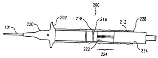
図1は、カテーテル近位部分104およびカテーテル遠位部分102を有する細長いカテーテルシャフト101を備えている撓み可能なカテーテル組立体100の実施形態を示している。カテーテル近位部分104は、2つの部分、すなわち、中間部分104′および近位部分104に更に分割されてもよい。各部分はカテーテルシャフト101の性能を最適にするために異なる剛性で構成されている。一実施形態では、カテーテル遠位部分102はカテーテル近位部分104より可撓性である。カテーテル近位部分104が2つの部分に分割されている実施形態では、中間部分104′は近位部分104より可撓性である。かくして、カテーテル遠位部分102は最も可撓性の部分であり、その後に中間部分104′が続く。カテーテル近位部分104はカテーテルシャフト101の可撓性の最も低い部分である。中間部分104′および遠位部分104はトルクを伝達するのに使用され、遠位部分102はカテーテル組立体100の撓みを行なう。
FIG. 1 illustrates an embodiment of a
カテーテル遠位部分102を撓ませるために、少なくとも1つのテンドン(以下を参照)がカテーテルシャフト101内に配置されている。図1に示すように、カテーテル遠位部分102は、撓まされると、丸まって撓み部分102−Dになる。撓みつまみ202を有するカテーテル取っ手200がカテーテル近位部分104のところでカテーテルシャフト101に連結されている。カテーテル取っ手200はカテーテル遠位部分102を撓ませるテンドンを制御するために制御機構(下記を参照)を有している。カテーテルシャフト101内には、ニードルのような少なくとも1つの治療器具(下記を参照)が配置されている。カテーテルシャフト101内に配置された治療器具に対する必要な連通または連結を許容する複数の連結ポート204がカテーテル取っ手200に設けられている。幾つかの実施形態では、ニードルのようなたった1つの治療器具がカテーテルシャフト101内に配置されている。ニードルの代わりに、或いはニードルに加えて、光力学的治療のような治療のために光エネルギを放出する光ファイバ束のような他の治療器具、または心筋内再血管形成を行なうチャンネリング器具を備えることもできる。これらの実施形態では、たった1つの連結ポート204がカテーテル取っ手200に設けられている。
At least one tendon (see below) is disposed within the
図2はカテーテル組立体100のカテーテルシャフト101の側面図を示している。カテーテルシャフト101は、テンドン130を有しているテンドン組立体103と、ニードル138を有しているニードル組立体109とを有している。テンドン組立体103およびニードル組立体109は、中央腔131内に配置されており、そしてカテーテル遠位部分102からカテーテル近位部分104まで連続的に延びている。カテーテル近位部分104において、テンドン組立体103は中心に(或いはほぼ中心に)位置決めされており、ニードル組立体109はカテーテルシャフト101の中心を外れて位置決めされている。カテーテル組立体100が1つより多いニードル組立体を有してもよいことはわかるであろう。変更例として、他の治療器具または診断器具がニードル組立体109に取って代わってもよく、或いはニードル組立体109に加えて、他の治療器具または診断器具が備えられてもよい。ニードルの代わりに、或いはニードル組立体109に加えて、光力学的治療のような治療のために光エネルギを放出する光ファイバ束のような他の治療器具、または心筋内再血管形成を行なうチャンネリング器具を備えることもできる。
FIG. 2 shows a side view of the
一実施形態では、テンドン組立体103およびニードル組立体109の各々はカテーテルシャフト101の中央腔131内に設けられた腔内に配置されている(図3および図4)。テンドン組立体103はテンドン腔26内に配置されており、ニードル組立体109は腔168内の配置されている。
In one embodiment, each of the
図3は遠位カテーテルシャフト118の横断面D1を示している。図3に示すように、テンドン組立体103は遠位カテーテルシャフト118の中心を外れて位置決めされており、ニードル組立体109は遠位カテーテルシャフト118のほぼ中心に位置決めされている。テンドン組立体103は、カテーテル組立体100の遠位部分102を撓ませることができるために中心を外れる必要がある。テンドン組立体103は、遠位カテーテルシャフト118に中心を外れて位置決めされているテンドン腔126内に配置されている。ニードル組立体109は、一実施の形態において遠位カテーテルシャフトのほぼ中心に位置決めされているニードル腔168内に配置されている。中央腔131は、テンドン組立体103およびニードル組立体109を固着するためにポリマーが充填されてもよい。中央腔131を取り囲んでいるのは圧縮ケージ122(以下に詳述)であり、圧縮ケージ122を取り囲んでいるのは遠位ジャケット120であり、この遠位ジャケット120は遠位カテーテルシャフト118のための外径を規定する。必要なら、追加の器具、構成部品またはニードル組立体を収容するために、遠位カテーテルシャフト118には、もっと多くの腔が配置されてもよい。
FIG. 3 shows a
図4は近位カテーテルシャフト112の横断面P1を示している。図4に示すように、テンドン組立体103は近位カテーテルシャフト112のほぼ中心に位置決めされている。幾つかの実施形態では、幾つかの中心を外れた腔、すなわち、腔166、167、168が近位カテーテルシャフト112に形成されている。ニードル腔168は先に述べたようにニードル組立体109により占められている。腔166、167の両方は、追加のニードル組立体(例えば、ニードル125を有するニードル組立体105およびニードル123を有するニードル組立体107)により、或いは変更例として、腔充填材により占められてもよいし、或いは占められなくてもよい。追加の中心を外れた腔を有することにより、近位カテーテルシャフト112に釣り合いをもたらす。釣り合いのために腔166、167が設けられる場合、これらの腔はテンドン腔126のように遠位カテーテルシャフト118の中へ延長される必要がない。
FIG. 4 shows a
図2に戻ると、撓み可能なカテーテル組立体100の構成部品の構成の詳細が示されている。図2では、カテーテルシャフト101は、近位カテーテルシャフト112および遠位カテーテルシャフト118と称される2つの部分に分割されている。
Returning to FIG. 2, details of the configuration of the components of the
遠位カテーテルシャフト118は遠位コアシャフト124を有しており、近位カテーテルシャフト112は近位コアシャフト116を有している。遠位コアシャフト124および近位コアシャフト116の各々はポリエーテルブロックアミド(ペバックス;これはアトフィナケミカルズの登録商標である)、ナイロンまたはポリウレタンのようなポリマーで作られている。遠位コアシャフト124用に使用される材料は近位コアシャフト116用に使用される材料より可撓性である(例えば、硬度ジュロメータが低い)。
幾つかの実施形態では、近位カテーテルシャフト112は中間カテーテルシャフト(符号を付していない)および近位カテーテルシャフト112に更に分割されている。中間カテーテルシャフトおよび近位カテーテルシャフト112は同様に構成されているが、異なる可撓性を有してもよい。使用中、近位カテーテルシャフト112は大腿部動脈および大動脈のような血管構造体の比較的まっすぐな部分に位置する。近位カテーテルシャフト112は主にトルクを伝達するように機能する。従って、近位カテーテルシャフト112はカテーテル組立体100の最も剛性の部分である。中間カテーテルシャフトは大動脈アーチ部のようなアーチ部分のまわりに位置してもよい。かくして、中間カテーテルシャフトはトルクを曲線にわたって伝達するはずである。従って、中間カテーテルシャフトは近位カテーテルシャフト112と比較して比較的可撓性であるはずである。異なる剛性部分を有する近位カテーテルシャフト112を生じるには、近位カテーテルシャフト112用に異なるジュロメータの材料が使用される。例えば、近位カテーテルシャフト112はナイロン12およびペバックス72Dのような高いジュロメータの材料で構成されることができ、中間カテーテルシャフトは、ペバックス63D、ペバックス63D混合物のような僅かに低いジュロメータの材料または更に低いジュロメータの材料で構成されることができる。
In some embodiments, the
図2に示すように、カテーテル近位部分104において、カテーテルシャフト101の最も外側の層は、近位取っ手の操作からのトルクをカテーテル遠位部分102に送出すことができるトルクシャフトとして機能する近位カテーテルシャフト112である。一実施形態では、近位カテーテルシャフト112は支持ポリマー層内に埋設された編組ワイヤで構成された支持編組層114で補強されたポリマー管で構成されている。支持編組層114は丸いまたは平らなワイヤおよびリボンの形態を有することができ、そしてステンレス鋼、NiTiのような金属またはナイロンおよびピークのような強ポリマーで構成されることができる。層114におけるワイヤのワイヤ横断面は丸い、矩形または任意の他の適当な形状であるあることができる。支持ポリマー層はナイロン、ペバックス、ポリウレタン、ポリオレフィンなどのようなカテーテル構成に一般に使用されているポリマーで構成されることができる。
As shown in FIG. 2, in the catheter
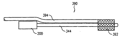
遠位カテーテルシャフト118は、テンドン130が引っ張られると、カテーテル遠位部分102を撓ませる可撓性部分である。遠位カテーテルシャフト118は低いジュロメータのペバックスのような低いジュロメータの材料の層を有している。遠位カテーテルシャフト118用に使用される低いジュロメータの材料は近位カテーテルシャフト112と比較して低い硬度規模を有しており、例えば、遠位カテーテルシャフト118用に使用される材料は約35Dの硬度規模を有してもよい。
The
遠位カテーテルシャフト118は少なくとも2つの機能、すなわち、カテーテル組立体100の内部構成部品の遠位部分を収容する機能と、カテーテル遠位部分の撓みを容易にする機能とを有している。図2および図3に示すように、遠位部分102は2つの構成部品、すなわち、遠位ジャケット120、圧縮ケージ122および遠位コアシャフト124で構成されている。遠位ジャケット120はカテーテル遠位部分102に収容されているカテーテル組立体100の内部構成部品のための外側包囲層として作用する。遠位ジャケット120はナイロン,ペバックス、ペバックス混合物および低ジュロメータの材料のようなポリマー材料で構成されている。カテーテル遠位部分102を撓ませる付勢を容易にするために、遠位カテーテルシャフト118は、引っ張られると、テンドン130が遠位カテーテルシャフト118を撓ませるためにカテーテル近位部分112用の材料より低いジュロメータおよび大きい可撓性の材料で構成される必要がある。
The
以下の段落はカテーテル組立体100の構成を詳細に説明している。カテーテル組立体100は外側構成部品に内側構成部品を構成する順序で構成されている。また、カテーテル近位部分104およびカテーテル遠位部分102は別々に構成され、そして互いに接合されてカテーテル組立体100を形成する。
The following paragraphs describe the construction of the
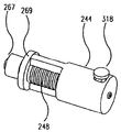
まず、テンドン組立体103を作製する。テンドン組立体103は、カテーテル近位部分104のところでカテーテル遠位部分102のところよりも剛性に製造されている。カテーテル近位部分104から始めて、テンドン組立体103を作製する。図5に示すように、テンドン組立体103は軸方向スパイン128と、少なくとも2組のスリップバンド132、134と、テンドン130とを有している。図6には、軸方向スパイン128が示されている。第1組のスリップバンド132を、軸方向スパイン128の遠位端部128−Dから短い距離(例えば、約2ないし9cm)を置いて設置する。残りのスリップバンド132は互いから同様な距離を置いて隔てられる。最も近位のスリップバンド134を、軸方向スパイン128の近位端部128−Pから短い距離(例えば、約2ないし9cm)を置いて設置する。これらのスリップバンド132、134は軸方向スパイン128と近位コアシャフト116との間のスリップを防ぐ。カテーテルシャフト101の構成が完了された後に、テンドン130を軸方向スパイン128内に配置する。
First, the
軸方向スパイン128は、撓み中、カテーテルの圧縮に対する耐性を与えることができる長さ方向に剛性の材料で製造されている。軸方向スパイン128は図2に示すように近位カテーテルシャフト112内で長さ方向に延びている。軸方向スパイン128は、近位カテーテルシャフト112の全長にわたって延びてもよいし、或いは近位カテーテルシャフト112とほぼ同じ長さを有してもよいし、近位カテーテルシャフト112と実質的に一致して位置決めされてもよい。かくして、軸方向スパイン128は近位カテーテルシャフト112と実質的に整合される。軸方向スパイン128は、テンドン130が引っ張られてカテーテル遠位部分102を撓ませるとき、(例えば、近位カテーテルシャフト112に沿った)カテーテルの圧縮および/またはニードル組立体の圧縮を阻止するのに使用される。カテーテルの圧縮は、カテーテルシャフト101に長さの変化を生じ、且つトルク応答保全性をゆがめるので望ましくない。ニードル組立体の圧縮は、ニードル組立体に長さの変化を生じてニードルの伸張の精度に影響する。軸方向スパイン128はNiTi、ステンレス鋼または他の金属合金のような材料で製造された金属管で構成されている。軸方向スパイン128は、その内径がテンドン130を受入れることができるように十分に寸法決めされるべきである。
The
スリップバンド132、134は金属管、バンドまたはリングで構成されることができる。変更実施形態では、スリップバンド132、134の各々はスタックコイル組立体(図示せず)で置き換えられることができる。スリップバンド132、134を有する軸方向スパイン128の端部はそれぞれ図2に部分108および部分110として示されている。軸方向スパイン128がテンドン130を取り囲んでいる状態では、カテーテル組立体100がテンドン130により圧縮下で引っ張られてカテーテル遠位部分102を撓ませると、軸方向スパイン128はカテーテル近位部分104の長さを一定に保持する。
The
カテーテル遠位部分102のために、テンドン103を図7のように作製する。テンドン組立体103の軸方向スパイン128は可撓性テンドンシース121で置き換えられている。その1つの理由は、テンドン組立体103がカテーテル組立体100の遠位部分102のところで可撓性である必要があり、その一方、テンドン組立体103が軸方向スパインのように圧縮を阻止することができるために近位部分104のところで剛性である必要があるからである。図7に示すように、可撓性テンドンシース121は軸方向スパイン128に接合されている。可撓性テンドンシース121は、図7に示すように、重なり空間98を形成するように、テンドンシース121の近位部分を軸方向スパイン128の遠位部分に重ねることによって軸方向スパイン128に接合されることができる。一実施形態では、可撓性テンドンシース121と軸方向スパイン128との間の重なり空間98に接着剤を分配する。変更例として、重なり空間98にテンドンシース121の壁部を貫通して開口部(図示せず)が生じられており、接着剤をこれらの開口部に分配して可撓性テンドンシース121を軸方向スパイン128に接合することができる。一実施形態では、カテーテルシャフト101を形成すべき次の熱融着工程中、可撓性テンドンシース121における開口部を維持するために、マンドレル148を可撓性テンドンシース121に挿入する。マンドレル148は可撓性テンドンシース121の内径を規定する。可撓性テンドンシース121の内径はテンドン130を受入れるように十分大きさに定められるべきである。可撓性テンドンシース121は遠位カテーテルシャフト118と実質的に整合され、かくして、遠位カテーテルシャフト118全体に沿って延びる。
For the catheter
一実施形態では、可撓性テンドンシース121は、ポリテトラフルオロエチレン(PTEF)またはテフロン(デュポンの登録商標)、高密度ポリエチレン(HDPE)、ポリエーテルエーテルケトン(PEEK)またはポリイミドでいくらか潤滑性の腔壁部を備えて製造される。軸方向スパイン128はステンレス鋼、ニッケルチタンまたはニチノール、または他の適当な材料で製造される。テンドン130はステンレス鋼のような強い引張強度を有する金属ワイヤである。
In one embodiment,
次に、遠位カテーテルシャフト118を作製する。図9には、多腔押出成形管150が示されている。この多腔押出成形管150は後でカテーテル遠位シャフト118用の遠位コアシャフト124を形成する。一実施形態では、多腔押出成形管150は腔152、154、156、158を有しており、腔156は中央腔にあり、腔152、154、158は腔156のまわりに半径方向に位置決めされている。カテーテルシャフト101のために腔がいくつ必要とされるかに応じて、図9に示すより多いまたは少ない腔を使用してもよいことはわかるであろう。腔156および側部腔のうちの1つ(例えば、腔152)には、スリットが切込まれている。これは、テンドン130が引っ張られているとき、カテーテル遠位部分102を撓ませるために、テンドン組立体103がカテーテルシャフト101の中心からカテーテルシャフト101の側部まで変化されることができるように、なされている。また、ニードル組立体109もまた、カテーテルシャフト101の側部からカテーテルシャフト101の中心まで変化されることができる。一実施形態では、中央腔156には、第1スリット160が切込まれている。この第1スリット160は、管150の近位端部からの短い距離(例えば、0.5ないし1.5cm)を除いて、多腔押出成形管150の長さのほとんどに及ぶ長さを有している。第2スリット162が側部腔152と中央腔156との間の壁部を貫通して切込まれている。この第2スリット162は第1スリット160の反対側に位置決めされている。第2スリット162は、多腔押出成形管150の近位端部からの短い距離(例えば、0.5ないし1.5cm)を除いて、多腔押出成形菅150の長さのほとんどに及ぶ長さを有している。第1スリット160はテンドン組立体103をカテーテルシャフト101の中心またはほぼ中心から遠位カテーテルシャフト118のところのカテーテルシャフト101の側部まで移動させるように形成されている。第2スリットは中心を外れた位置からほぼ中心の位置までニードル組立体109を移動させるように形成されている。
Next, the
次に、近位カテーテルシャフト112を作製する。図10Aには、多腔押出成形管151が示されている。多腔押出成形管151は後でカテーテル近位シャフト112用の近位コアシャフト116を形成する。一実施形態では、多腔押出成形管151はテンドン腔126と、ニードル腔166、167、168とを有しており、テンドン腔126は中央腔にあり、ニードル腔166、167、168は腔126のまわりに半径方向に位置決めされる。カテーテル組立体100のために腔がいくつ必要とされるかに応じて、もっと多いまたは少ない腔を使用してもよいことはわかるであろう。低摩擦ライナーを腔に挿入し、すなわち、ライナー174をテンドン腔126に挿入し、ライナー136をニードル腔168に挿入し、ライナー170をニードル腔167に挿入し、ライナー172をニードル腔166に挿入する。これらのライナーはPTFEまたはTEFLON、HDPE、PEEKまたはポリイミドで製造されることができる。ライナーの各々にマンドレルを挿入して各腔の内径を規定し、すなわち、マンドレル182をライナー174に挿入し、マンドレル180をライナー172に挿入し、マンドレル178をライナー170に挿入し、マンドレル184をライナー136に挿入する。
Next, the
テンドン腔126用のライナー174はカテーテル近位部分104(図2)の長さより短い。ライナー174はカテーテル近位部分104の部分108、110間である部分の長さにほぼ等しい長さを有している。また、ライナー174は軸方向スパイン128が自己調整する自由度を与えるために、従って、カテーテルシャフト101の回動または前進中、トルク応答抵抗を減じるために、軸方向スパイン128の外径よりわずかに大きい内径を有している。部分108、110にライナーを有していないことにより、カテーテル近位シャフト112からの材料が、熱融着法における収縮管の圧縮下においてスリップバンド132、134および軸方向スパイン128のまわりに崩壊して軸方向スパイン128の両端部を固定する。側部腔用のライナー136、170、172はライナー174の長さより長い。ライナー136、170、172の各々の特別の長さが、図9に示すように作製された遠位カテーテルシャフト118における腔に入る。ライナー136、170、172の各々は管のポリマーに対するそれらの付着を増大するために化学的に処理(例えば、エッチング)されてもよい。
The
腔のうちの幾つかが釣り合せの目的でのみ設けられている実施形態では、ライナーおよびマンドレルは遠位カテーテルシャフト118における腔の中へ延長されない。最終の熱融着後、腔を開いた状態に保つためにライナーおよびマンドレルが無いので、遠位カテーテルシャフト118における特別の腔が閉じられる。近位カテーテルシャフト112においてカテーテルシャフト101の釣り合わせが必要とされるだけである。
In embodiments where some of the cavities are provided only for balancing purposes, the liner and mandrel are not extended into the cavities in the
図10Bにおいて、ライナーおよびマンドレルを有する管151を覆って収縮管186を設置し、全体の組立体を熱源下で改質する。部分108と部分110との間に位置決めされた部分のみ(図2)を加熱する。加熱された部分におけるポリマーが収縮管の圧縮下で溶融し、ライナー上に崩壊して多腔近位コアシャフト116を形成する。収縮管は近位コアシャフト116の外径を規定するのを助け、マンドレルは腔の内径を規定する。
In FIG. 10B, a
図10Cにおいて、テンドン腔126用のマンドレルを取り出す。この時点で、近位カテーテルシャフト112が作製される。図10Dにおいて、この時点まで、可撓性テンドンシース121と、軸方向スパイン128と、スリップバンド132、134とを有しているテンドン組立体103を、図8に示されるマンドレル148と共にテンドン腔126内に挿入する。スリップバンド132、134はそれぞれ近位カテーテルシャフト112の部分108、110の下に位置決めされるべきである。
In FIG. 10C, the mandrel for
次に、図10Eに示すように、遠位コアシャフト(多腔押出成形管150)を近位コアシャフト(多腔押出成形管151)に連結する。初めは多腔押出成形管151から張出しているマンドレルおよびライナー136、170、172の夫々の特別長さを多腔押出成形管150の腔に挿入する。マンドレル148および可撓性テンドンシース121を多腔押出成形管150の中央腔156に挿入する。第1スリット160の近位端部において、テンドンシース121およびマンドレル148を中央腔156から出し、そして第1スリット160により形成される壁空間に沿って設置する。これにより、熱融着法後にカテーテル遠位部分102における(図2および図3に示される)中心を外れたテンドン腔126を形成する。テンドン組立体103のテンドン130は、後で、後述のようにテンドン腔126内に配置される。
Next, as shown in FIG. 10E, the distal core shaft (multi-lumen extruded tube 150) is connected to the proximal core shaft (multi-lumen extruded tube 151). Initially, the special lengths of the mandrels and
また図10Eにおいて、ライナー136、170、172の各々を(それらの夫々のマンドレルと共に)側部腔のうちのそれぞれの1つに挿入する。一実施形態では、第2スリット162の近位端部において、ライナー136およびマンドレル184を、中央腔164の形成の準備をするために管150の中心に入れる。これにより、カテーテル遠位部分102のための中心ニードル腔164を形成する。
Also in FIG. 10E, each of the
次に、遠位コアシャフト124および近位コアシャフト116を形成する。図10Eにおいて、収縮管188を多腔管150と、多腔管151の部分108(図2)とに設置する。収縮管188は遠位コアシャフト124の外径を規定する。近位コアシャフト116の外径を規定する収縮管186もまた、図10Bないし図10Eに示すように、多腔管150に設置する。遠位部分102および近位部分104の部分108を加熱源下で加熱する。また、近位部分104の部分110もまた加熱源下に置く。圧縮下でポリマーが溶融し、崩壊して収縮管188、186から支持マンドレルに入って遠位コアシャフト124および近位コアシャフト116の形成を行なう。熱融着法の後、収縮管188、186を形成された遠位コアシャフト124および近位コアシャフト116から取り出す。
Next, the
次に、遠位カテーテルシャフト118および近位カテーテルシャフト112を形成する。一実施形態では、圧縮ケージ122(以下に詳述)を遠位コアシャフト124に設置する(図2および図3)。支持編組層114を近位コアシャフト116に設ける(図2)。この支持編組層114はステンレス鋼、ナイロン、PEEKまたは冷間加工ニチノールのような材料で製造されることができる。遠位ジャケット120を形成する支持ポリマー層を圧縮ケージ122に設ける。次いで、支持ポリマーに外側収縮管(図示せず)を設置する。また、支持ポリマー層を支持編組層114に設け、外側収縮管をこのポリマー層に設置する。熱融着後、ポリマー内に編組層を埋設する。これらの外側収縮管はカテーテルシャフト101の外径を規定する。熱融着後に、外側収縮管を取り出して遠位カテーテルシャフト118および近位カテーテルシャフト112を完成する。
Next, the
一実施形態では、遠位カテーテルシャフト118について、遠位ジャケット120を覆う外側収縮管の両端部にのみ熱を加える。熱融着法の後、圧縮ケージ122の両端部のみを遠位ジャケット120に取付ける。かくして、圧縮ケージ122は遠位ジャケット120内でより自由に移動することが許容される。かくして、圧縮ケージ122により、撓ませ中、カテーテル遠位部分102内の内部構成部品を移動させ、かくして撓み剛性を低下させることができる。
In one embodiment, heat is applied only to the
近位カテーテルシャフト112について、外側収縮管の全長にわたって熱を加える。ポリマーが支持編組層114の中へ融入して近位カテーテルシャフト112を形成する。
カテーテルシャフト101が形成された後、マンドレルを取り出すことができる。マンドレルの取り出し後、腔は空になる。次いで、必要なら、カテーテル組立体100の内部構成部品をカテーテルシャフト101内に配置することができる。必要なら、カテーテルシャフト101の釣り合いを維持するために、不占有腔に腔充填材を充填することができる。
For the
After the
圧縮ケージ122およびそれを製造する方法は、米国特許第2002−01665461号、現在は米国特許第6,585,718号(これは出典を明示することにより本願明細書の開示の一部とされる)に詳細に記載されている。圧縮ケージ122は、カテーテル遠位部分102の軸方向長さを維持するように機能し、カテーテル遠位部分102の伸びを防ぎ、カテーテル遠位部分102の脱出またはねじれを阻止し、カテーテル遠位部分102の内腔統合性を維持し、そして解剖学的構造との治療器具の係合のための支持を行なう。圧縮ケージ122は可撓性を維持しながら軸方向および半径方向の圧縮荷重を阻止するように構成されている。
圧縮ケージ122の種々の構成が図11Aないし図11Eで見られる。圧縮ケージ122は近位端部122−Pと、遠位端部122−Dと、これらの端部の間の中央腔122−Lとを有している。圧縮ケージ122は、理想的には、徐重すると、まっすぐのような予備設定形状に戻る傾向があるように、ニチノール、ばね性オーステナイトステンレス鋼または熱処理可能なステンレス鋼のような弾性材料から製造される。いくつかの実施形態では、圧縮ケージ122は、NiTi、ステンレス鋼または他の金属合金のような前述の材料を使用してステント状構造であるように構成されている。
Various configurations of the
一実施形態では、図11Aに示すように、圧縮ケージ122は平らなワイヤコイル326および2つの実質的に長さ方向のストラット328を有している。これらのストラット328は、互いに直径方向に対向されていて、コイル326の幾つかまたはすべてのループに溶接されたり、はんだ付けされたり、ロウ付けされたり、接着されたり、或いは他の方法で取付けられたりされる。
In one embodiment, the
他の実施形態では、図11Bに示すように、圧縮ケージ122は丸いワイヤコール330および2つの実質的に長さ方向のストラット332を有している。これらのストラット332は、互いに直径方向に対向されていて、コイル330の幾つかまたはすべてのループに溶接されたり、はんだ付けされたり、ロウ付けされたり、接着されたり、或いは他の方法で取付けられたりされる。
In other embodiments, as shown in FIG. 11B, the
他の実施の形態では、図11Cおよび図11Dに示すように、圧縮ケージ122は、互いに直径方向に対向されている一連の深い切欠き336を有する実質的に管状の部材334を有している。対向した切欠き336間に残っている材料はストラット338として機能する。これらのストラット338は、腔の長さ方向軸線に対して垂直に整合されるか、或いは螺旋角度で整合される(図11Aないし図11E)。
In other embodiments, as shown in FIGS. 11C and 11D, the
更に他の実施形態では、図11Eに示すように、圧縮ケージ122は線状の一連のリング340と、これらのリング340を相互に連結する2つの実質的に長さ方向のストラット342とを有している。これらのストラット342は、互いに直径方向に対向されていて、コイル330の幾つかまたはすべてのループに溶接されたり、はんだ付けされたり、ロウ付けされたり、接着されたり、或いは他の方法で取付けられたりされる。
ストラット328、332、338、342の主な機能は圧縮ケージ122に柱状強度を与えることである。引張荷重が操向テンドン130に加えられてカテーテル遠位部分102の撓みを誘発すると、荷重の反作用が圧縮ケージ122内でストラット328、332、338、342により移送され、そしてカテーテル近位部分104に伝達される。圧縮ケージ122は、一対の対向しているストラット328、332、338または342が位置決めされている平面に対して垂直である方向に最も容易に横方向に撓む。
圧縮ケージ122は、溶融接合、接着または幾つかの同等な機械的結合技術により遠位カテーテルシャフト120の内面に取付けられてもよい。変更例として、圧縮ケージ122は遠位カテーテルジャケット120と組み合わされて1つの一体構成部品とされてもよい。変更例として、圧縮ケージ122は、その遠位端部および近位端部が対向したストラット328、332、338、342を介して軸方向荷重を伝達するように連結されているならば、遠位カテーテルシャフト118内に緩く存在してもよい。一実施形態では、熱源は、圧縮ケージ122の遠位部分122−Dおよび近位部分122−Pの上方に付与されるだけであって、ポリマーのみが溶融してこれらの2つの部分の中に入るようになっている。かくして、圧縮ケージ122は遠位部分122−Dと近位部分122−Pとの間の部分に緩く位置する。
In yet another embodiment, as shown in FIG. 11E, the
The main function of the
The
変更実施形態では、圧縮ケージ122は図12に示される螺旋形コイル構造体165と置き換わられている。この螺旋形コイル構造体165はステンレス鋼、ナイロンまたはニチノールのような弾性材料で製造されることができる。螺旋形コイル構造体165は丸いワイヤまたはリボンで構成された編組メッシュであることができる。熱融着法中、熱源は螺旋形コイル構造体165の遠位部分および近位部分に付与される。遠位ジャケット120からの低いジュロメータをゆするポリマーが溶融してこれらの2つの部分に入る。螺旋形コイル構造体165は圧縮ケージ122の場合と同様に遠位部分と近位部分との間の部分に緩く存在する。変更例として、螺旋形コイル構造体165の全体部分を横切って熱を加えることができ、ポリマーが螺旋形コイル構造体165全体にわたって溶融する。
In a modified embodiment, the
カテーテルシャフト101が形成された後、カテーテル遠位部分102の近位端部の近くに変化部分106が形成される。幾つかの特徴がこの変化部分106を構成する。第1に、テンドン組立体103が、変化部分106のところで中心から外れるようにカテーテルシャフト101の中心から変位され、かくしてテンドン130が引っ張られるとき、中心を外れたモーメントを生じる。第2に、遠位カテーテルシャフト118は近位カテーテルシャフト104と比較してより可撓性にされており、かくしてテンドン130からの引張下で撓みのための付勢力を生じる。第3に、幾つかの実施形態では、テンドン組立体130の位置の変化に加えて、ニードル組立体109は遠位カテーテルシャフト118の中心に向けて移動される。第4に、テンドン130が機能するより大きい可撓性を考慮して可撓性テンドンシース121がこの部分で軸方向スパイン128に取って代わっている。第5に、近位カテーテルシャフト112は遠位カテーテルシャフト118まで変化されている。第6に、近位コアシャフト116は圧縮ケージ122および遠位コアシャフト124まで変化されている。
After the
次に、ニードル組立体109をカテーテルシャフト101内に配置する(図2)。1つより多いニードル組立体(例えば、ニードル組立体109)をカテーテルシャフト101内に配置してもよいことはわかるであろう。例えば、図4に示すように、ニードル組立体109とともにニードル組立体105、107を設ける。ニードル組立体109、105、107の各々は、腔内のニードル組立体の移動を容易にするためにニードル組立体の外側に配置された(例えば、PTFEまたはTEFLON製の)潤滑性または低摩擦のニードルシースを有してもよい。変更例として、各ニードル組立体は、腔内のニードル組立体の移動を容易にするために潤滑性の材料で被覆されてもよいし、或いは潤滑性の材料で製造されてもよい。各ニードル組立体はカテーテルシャフト101の遠位端部からカテーテルシャフト101の外側まで伸張可能である。カテーテルシャフト101の遠位端部のところで、ニードルシースは遠位先端アンカー140に接着されるか、或いは他の方法で付着されてもよい。カテーテルシャフト101の遠位端部は、ニードル組立体109をカテーテルシャフト101から出して目標の部位に達するようにするために出口開口部97を有している。一実施形態では、各ニードル組立体は注入ポート(例えば、図1に示される連結ポート204)に連結されている。各ニードル組立体は、金属、ステンレス鋼、ニチノール、ポリマーまたはそれらの組合せのような耐久性材料で製造されたニードルを有している。このニードルは当業界で知られているような任意の在来のニードルであることができる。ニードルは、代表的には、これを治療のために目標部位に入れるために勾配付き先端部または鋭い先端部を有している。
Next, the
次に、テンドン130をカテーテルシャフト101内に配置する。このテンドン130は、カテーテルシャフト101の内部構成部品すべてがカテーテルシャフト101に組み入れられた後にカテーテルシャフト101に挿入されるだけである。図2を参照して説明すると、カテーテル組立体100は遠位カテーテルシャフト118の遠位端部のところに遠位先端アンカー140を有している。この遠位先端アンカー140は、一実施の形態では、ステンレス鋼、白金合金、黄銅などのような金属材料で製造される。遠位先端アンカー140は、例えば、接着剤、溶接、はんだ付け、クリンプ加工、機械的締めなどにより圧縮ケージ122および遠位カテーテルシャフト118に連結される。
Next, the
一実施形態では、遠位先端アンカー140はテンドンアンカーとして機能する。テンドン130は接着剤、溶接、はんだ付け、クリンプ加工、機械的締めまたは他の適当な技術により遠位先端アンカー120の壁部に連結される。一実施形態では、テンドン130が遠位先端アンカー120に連結された後、このテンドン130を遠位カテーテルシャフト118の遠位端部からテンドン腔126に挿入する。テンドン130を、これが近位カテーテルシャフト112に達し、そして近位カテーテルシャフト112から延出するまで近位方向に押す。
In one embodiment,
テンドン130は高い降伏強さおよび高い弾性強さを有する金属ワイヤで製造される。テンドン130をこのような特性を備えるように製造するのにステンレス鋼または冷間加工ニチノールを使用することができる。テンドン130は丸い、矩形または他の適当な形状の横断面を有することができる。変更例として、テンドン130はケブラー(これはデュポンの登録商標である)のようなポリマー材料から製造されることもできる。
The
テンドン130およびニードル(例えば、ニードル123、125または138)の移動はカテーテルシャフト101の近位端部に取付けられたカテーテル取っ手200(以下を参照)によって制御される。テンドン130は制限走行距離を有する(カテーテル取っ手200に含まれる)プル機構に連結されている。テンドン130が引っ張られると、カテーテル遠位部分102が撓む。プル機構の走行距離は任意の位置に固定されることができ、手動力下で動くだけである。
Movement of the
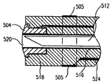
図13は、一実施形態において、ニードル止め機構がカテーテル組立体100に組み入れられていることを示している。この図に示すように、ニードル138はリングストップ190と、相補腔ストップ192を有するニードル138を収容するニードル腔164とを有している。リングストップ190は、溶接、はんだ付けおよび接着剤の使用のような在来の方法によりニードル138の外壁部に取付けられている。腔ストップ192は、(例えば、熱融着または接着剤により)腔の内壁部に取付けられており、そしてリングストップ190に対して相補であるように構成されている。かくして、リングストップ190が腔ストップ192に接触する(または係合する)と、ニードル138は接触点より更に遠くへ前進するのが防がれる。かくして、リングストップ190および腔ストップ192はニードル138の遠位方向の走行距離を規定する。腔164の内壁部はまた、腔ストップ192に対して近位の部分に腔ストップ192と同様な他の腔ストップ(図示せず)を有することができる。この他の腔ストップはリングストップ190と共にニードル138の近位方向の走行距離を規定することができる。かくして、リングストップ190が近位領域において他の腔ストップに接触する(或いは係合する)と、ニードル138は近位方向に更に遠くに走行するのが防がれる。
FIG. 13 illustrates that in one embodiment, a needle stop mechanism is incorporated into the
図13はまた、一実施形態において、電極装置がカテーテル組立体100に組み入れられていることを示している。一実施形態では、カテーテル遠位シャフト118は先端電極を有している。この先端電極は遠位先端アンカー140と同じ構成部品であることができるか、或いは遠位先端アンカー140に組み入れられることができる。先端電極には、導電性リード144が接続されており、このリード144は近位家テーテルシャフト112(この図には図示せず)および近位取っ手200(この図には図示せず)を通って遠位カテーテルシャフト118に沿って延びていて、カテーテル組立体100の外側で検出装置(図示せず)に接続されている。一実施形態では、他の電極142が遠位カテーテルシャフト118に組み込まれている。この電極142は電極装置用の照合電極として作用することができる。変更例として、電極140、142は、照合電極がほかの場所、例えば、患者の身体に取付けられた独立した電極として機能することができる。電極142は先端電極に近接してその近くに設置されている。他の導電性リード144が電極142に接続されていて、カテーテル組立体100の外側まで延びている。
FIG. 13 also shows that in one embodiment, an electrode device is incorporated into the
電極装置はカテーテル組立体100用の多くの有用な用途をもたらす。電極装置はカテーテル組立体100のためのマッピング上方および/または局部薬剤送出し情報をもたらすことができる。また、電極装置は、局部心臓信号と、カテーテルと心室の壁部との間の壁接触とを感知することを考慮しており、これは生物学的物質の送出しに有用である。電極装置の構成における更なる詳細を以下に示してある(図32−34、図35A−35F、図36A−36Bおよび図37A−37B)。
The electrode device provides many useful applications for the
図14A−14Cは、幾つかの実施形態において、予備成形された遠位部分を有するガイドシースがカテーテル組立体100または他のカテーテル組立体に配置されていることを示している。図14Aは、患者へのカテーテル組立体100の導入を容易にするためにカテーテル組立体100に設置されることができるガイドシース194を示している。このガイドシース194は、近位部分191と、遠位先端部199を有する予備成形遠位部分198とを有している。ガイドシース194は遠位部分198および近位部分191を通って延びている細長い腔193を有している。この細長い腔193はカテーテル組立体100のようなカテーテル組立体を挿通するのに十分である内径を有するように構成されている。ガイドシース194は、カテーテル組立体100に使用されるのに限定されず、カテーテル組立体100の別の具体例、例えば、後述のカテーテル組立体400または344を含めて、多くの異なる種類のカテーテル組立体の導入を容易にするために使用されることができる。一実施形態では、ガイドシース194は、曲りくねった経路にわたるガイドシース194の操縦を助けるために近位部分191より可撓性である中間部分を有している。
14A-14C illustrate that in some embodiments, a guide sheath having a preformed distal portion is disposed on the
ガイドシース194は、最も内側の腔における潤滑性ライナー187と、ライナー187の頂部における編組ワイヤ層189とを横断面図196に示すようにポリマージャケットにより互いに融着させて構成されている。ガイドシース194の剛性はガイドシース194の部分すべてに沿って変化している。近位部分191は遠位部分198より剛性である。遠位先端部199は非外傷性先端部を生じるために軟質材料によりライニングされている。
The
予備成形遠位部分198は1つの斜め曲り部または2つの斜め曲り部(または二重斜め曲り部)を有することができる。予備成形遠位部分198は近位部分191に対して角度を有している。角度は任意の適当な角度であってもよく、例えば、角度は65度から160度まで変化してもよい。図14Bは、一実施形態において、予備成形遠位部分198が50度と160度との間で変化する角度を有する単一の斜め曲り部である斜め曲り部198−Sを有していることを示している。図14Cは、一実施形態において、予備成形遠位部分198が、各々が約50度と160度との間で変化する角度を有する2つの曲り部分を有する二重斜め曲部分である斜め曲り部198−Dを有していることを示している。
The preformed
ガイドシース194は洗浄ポート195および自己シール弁197を有する取っ手185に連結されてもよい。一実施形態では、ガイドシース194はその近位端部のところで取っ手に連結されている。撓み可能なカテーテルシャフトがガイドシース194の中央腔に入るように取っ手に挿入されている。洗浄ポート194は撓み可能なカテーテルシャフトとガイドシース194の中央腔との間の空間を洗浄するのに使用される。自己シール弁197はカテーテルを通って移動する流体(例えば、血液)の逆流を防ぐために撓み可能なカテーテルシャフトのまわりのシールとして(例えば、取っ手内に)設けられている。また、自己シール弁197はガイドシース194に対する撓み可能なカテーテルの配向を固定するために固定具として使用されることもできる。固定は、撓み可能なカテーテルシャフトのまわりきつく固定するために中央腔と同軸のガイドシース194の近位アダプタの内側に捕獲されたOリングを圧縮することにより達成されることができる。
The
一実施形態では、治療手順中、まず、ガイドシース194を、ガイドワイヤ(図示せず)上の追跡により患者の大動脈および大動脈弁を通して左心室に挿入する。次いで、ガイドワイヤを抜き出す。ガイドシース194はカテーテル組立体100を挿通することができる通路を生じる。次いで、操向可能なカテーテル組立体100のようなカテーテル組立体(またはここに記載の他のカテーテル組立体のうちの1つ)を、ガイドシース194を通して心室に挿入する。カテーテル組立体が心臓の室にあると、ガイドシース195は操向可能なカテーテル組立体100に対する支持を行い続けることができる。その遠位部分198はカテーテル組立体100に追加の方向を与えることができる。
In one embodiment, during the treatment procedure, the
図15A−15Dは、幾つかの実施の形態において、カテーテルシャフト101から延出可能である構成部品であるニードルだけを有する代わりに、ニードルは延長可能であるように構成されることもできるニードル管により保護されることができる。図15A−15Bは、図2のニードル138を例にとって、延長可能なニードル138が延長可能なニードル管137の腔139内に配置されていることを示している。延長可能なニードル管137はニードル138を支持するのに適切な強さを有するように構成されている。ニードル管137は、編組ワイヤ層が腔139の外側に設けられ、そしてポリマージャケットに埋設されて構成されてもよい。ニードル管137は、これをカテーテルシャフト101におけるニードル腔内で容易に走行させるために低い摩擦を有する外壁部を有している。延長可能なニードル管137は前述のようにカテーテルシャフト101に生じられた腔内に配置されている。
15A-15D illustrate a needle tube that, in some embodiments, may have a needle that can be extended instead of having only a needle that is a component that can extend from the
図15Cは、一実施形態において、まっすぐ延びているニードル138を有する代わりに、ニードル138が発散角度で延出するように構成されることができることを示している。これにより、注入帯域の直径を増大し、且つ注入軌道の長さを増大する。ニードル138は、超弾性NiTi材料で製造され、そしてニードル138がニードル管137から延出されるにつれて先端部分135が外方に曲がるように予備成形されることができる。
FIG. 15C illustrates that, in one embodiment, instead of having a straightly extending
図15Dは、一実施形態において、カテーテル組立体100に含まれるニードルすべてが、これらがそれらの夫々のニードル管から延出されるにつれて発散傾斜される先端部分を有してもよいことを示している。この実施の形態は良好な注入帯域の直径および良好な注入軌道の長さを考慮している。更に、ニードルの各々(例えば、ニードル138)はカテーテルシャフト101の出口開口部の近くで側壁部に向けて傾斜されている。変更例として、個々のニードルを収容している夫々の延長可能なニードル管の各々もまた、ニードルがカテーテルシャフト101の軸線に対して或る角度で導き出されるように出口開口部の近くで側壁部に向けて傾斜されることができる。ニードルは独立して或いは遠位先端部のところのジョイント149と共に延びてもよい。図15Dにおいて、3つのニードルのすべてがジョイント149に取付けられており、かくして、これらのニードルはすべて一緒に延出されることができる。各ニードルが傾斜されたニードル先端部分を有する場合、これらのニードルのための注入帯域および注入軌道の長さが改良される。
FIG. 15D illustrates that in one embodiment, all of the needles included in the
他の実施形態では、膨らまし可能なバルーン141がテンドン腔126の外壁部に組み付けられている。このバルーン141はニードルを収容しているニードルシースの下に設置されている。バルーン141を膨らませることにより、ニードル(例えば、ニードル138、123、125)が側方に押され、従って、中央軸線に対して或る角度で延出される。図15Dに示すように、バルーン141が収縮状態145にあるとき、ニードルは外方に突出されなく、バルーン141が膨らまされた状態にあるとき、ニードルは外方に突出される。バルーン141は、その膨らましを見込んでいる少なくとも1つのバルーン腔143を有してもよい。変更例として、バルーン141は、各部分が独立して膨らまされるように個々の膨らまし腔143を持つ部分を有してもよい。かくして、個々のニードルは独立して制御されることができる。
In other embodiments, an
一実施の形態では、各ニードルにおける注入箇所を増やすために、端部に1つの注入穴を有する代わりに、各ニードルの側部にもっと多い穴または開口部を形成することができる。従って、注入された剤は1つの箇所に集中されるのではなく、より拡散される。 In one embodiment, more holes or openings can be formed on the side of each needle instead of having one injection hole at the end to increase the number of injection points in each needle. Thus, the injected agent is more concentrated rather than concentrated in one place.
図16はニードルがテンドンに巻き付けられている撓み可能なカテーテル組立体400の模範的な具体例を示している。カテーテル組立体400は内部構成部品の釣り合い分布をもたらしている。 FIG. 16 shows an exemplary embodiment of a deflectable catheter assembly 400 with a needle wrapped around a tendon. Catheter assembly 400 provides a balanced distribution of internal components.
カテーテルシャフトおよび内部構成部品を有するカテーテル組立体が大動脈アーチ部を通って左心室に入るように血管系に使用される場合、曲りくねりが遭遇される。大動脈アーチ部のような血管系の曲りくねった部分に存在しているカテーテル組立体の場合、カテーテルシャフトのトルクの応答が、非対称に位置決めされた内部構成部品に起因して生じられるいずれかの不釣り合いの力/モーメントにより容易に影響されてしまう。例えば、ニードルのような内部構成部品が中心を外れた位置決めされていれば、ニードルが存在する方のカテーテルシャフトの側(ニードル側と称される)が非ニードル側より剛性である。カテーテルシャフトは、より剛性な側が曲がり曲線の外側にある状態で曲がった血管部分に位置するのがよい。より剛性な側を曲がり曲線の外側か、内側かに有する結果、エネルギの最も低い状態、従って、安定な位置となる。カテーテルオペレータが、例えば、カテーテル遠位部分を1つの心室壁部から他の心室壁部に差し向けるように、カテーテルを、そのより剛性の側を安定な位置から離して回転させようと試みるなら、カテーテルは「突進する」ことになる。 Bends are encountered when a catheter assembly having a catheter shaft and internal components is used in the vasculature to enter the left ventricle through the aortic arch. In the case of a catheter assembly that resides in a tortuous portion of the vasculature such as the aortic arch, the response of the catheter shaft torque is caused by any non-uniformity caused by asymmetrically positioned internal components. It is easily affected by the balance force / moment. For example, if an internal component such as a needle is positioned off-center, the side of the catheter shaft where the needle is present (referred to as the needle side) is more rigid than the non-needle side. The catheter shaft may be located in a bent vessel portion with the stiffer side being outside the bend curve. Having the stiffer side either outside the curve or inside the curve results in the lowest energy state and hence a stable position. If the catheter operator attempts to rotate the catheter away from its stable position, eg, to direct the distal portion of the catheter from one ventricular wall to another, The catheter will “push”.
突進は、好適な配向からの逸れに対する、湾曲導管(例えば、大動脈、または他の曲りくねった解剖学的構造)の内側のカテーテルシャフトの増大抵抗により、および好適な配向への転向に対するカテーテルシャフトの減少抵抗により引起こされる。この好適な配向は、カテーテルシャフトの横断面にわたる不釣り合いの剛性(曲げ弾性率)により、および/またはカテーテルシャフトの任意の自然の或いは誘発された湾曲により発生されることができる。例えば、カテーテルシャフト内の中央腔を通って延びるニードルを有するカテーテル組立体では、テンドンが中心を外れて設置されている。この場合、想像することができるように、カテーテルシャフトの横断面はテンドンおよびその腔構成により生じられる不釣り合いの横断面を有する。テンドン組立体が同様な半径方向位置において他のシャフト材料より高い剛性(高い曲げ弾性率)であれば、テンドン組立体は曲線の外側に向けてそれ自身を安定化する傾向を有する。テンドン組立体が同様な半径方向位置において他のシャフト材料より低い剛性(低い曲げ弾性率)であれば、テンドン組立体は曲線の内側に向けてそれ自身を安定化する傾向を有する。シャフトの好適な配向はカテーテルシャフトの最も低い保存エネルギ状態であり、従って、安定な状態である。好適な配向から180度の配向はカテーテルシャフトの最も高い保存エネルギ状態であり、従って、不安定な状態である。もちろん、多数の高い剛性/低い剛性の半径方向のシャフト部分は、多数の好適な配向になり、従って種々の回転角度で多数の安定および不安定な配向になる。カテーテルシャフトの回転中の隣接した高いおよび低いエネルギ保存状態の間の差が大きければ大きいほど、突進または高いエネルギ保存ピークの近くの回転不安定度が大きくなり、低いエネルギ保存谷部からの逸れに対する抵抗が大きくなる。 Rushing is due to the increased resistance of the catheter shaft inside a curved conduit (eg, aorta, or other tortuous anatomy) against deviation from the preferred orientation, and the catheter shaft against turning to the preferred orientation Caused by reduced resistance. This suitable orientation can be generated by unbalanced stiffness (flexural modulus) across the cross section of the catheter shaft and / or by any natural or induced curvature of the catheter shaft. For example, in a catheter assembly having a needle that extends through a central lumen in the catheter shaft, the tendon is placed off center. In this case, as can be imagined, the cross section of the catheter shaft has an unbalanced cross section caused by the tendon and its cavity configuration. If the tendon assembly is stiffer (high flexural modulus) than other shaft materials at similar radial locations, the tendon assembly tends to stabilize itself towards the outside of the curve. If the tendon assembly is less stiff (low flexural modulus) than other shaft materials at similar radial locations, the tendon assembly will tend to stabilize itself towards the inside of the curve. The preferred orientation of the shaft is the lowest stored energy state of the catheter shaft and is therefore a stable state. An orientation of 180 degrees from the preferred orientation is the highest stored energy state of the catheter shaft and is therefore an unstable state. Of course, a large number of high stiffness / low stiffness radial shaft portions will result in a number of suitable orientations and thus a number of stable and unstable orientations at various rotational angles. The greater the difference between adjacent high and low energy conservation states during rotation of the catheter shaft, the greater the rotational instability near the rush or high energy conservation peak, and the deviation from the low energy conservation valley Resistance increases.
この問題は、テンドンが引っ張られて遠位部分を撓ませるときに、より顕著になる。このとき、カテーテルの回転は、不釣り合いの横断面の剛性に因り好適な配向に対してだけでなく、カテーテルシャフトの一方の側(テンドンを有する側)で優先的に生じる圧縮荷重に対しても作用しなければならない。この不釣り合いの圧縮荷重はシャフトに加えられる曲げモーメントであると考えることができる。湾曲導管においては、好適な配向(カテーテルシャフトの最も低い保存エネルギ状態)はカテーテルシャフトの圧縮側が曲線の内側に向けて配向された状態である。カテーテルシャフトがこの好適な配向から逸れると、何故なら、テンドン腔の経路長さが曲線の外側に向けて増大する傾向があるので、テンドンの比較的固定された長さにより、シャフトが更に圧縮される。これは、カテーテルシャフトのエネルギ保存を劇的に増して、カテーテルシャフトのテンドン側が湾曲の外側に向けて配向されるような回転不安定性の大きな弧(突進)を生じる。その結果、シャフトの横断面にわたる不釣り合いの剛性または圧縮では、カテーテルを回転で操ることは非常に困難である。これらの力は、代表的には、例えば図2について論述した実施形態におけるように、非対称に位置決めされたテンドンおよび/またはニードル構成部品により発生される。 This problem becomes more pronounced when the tendon is pulled to deflect the distal portion. At this time, the rotation of the catheter is not only for the preferred orientation due to the stiffness of the unbalanced cross-section, but also for the compressive load that preferentially occurs on one side of the catheter shaft (the side with the tendon). Must act. This unbalanced compressive load can be thought of as a bending moment applied to the shaft. In a curved conduit, the preferred orientation (the lowest stored energy state of the catheter shaft) is that with the compression side of the catheter shaft oriented towards the inside of the curve. If the catheter shaft deviates from this preferred orientation, the tendon cavity's path length tends to increase toward the outside of the curve, so that the relatively fixed length of the tendon further compresses the shaft. The This dramatically increases the energy storage of the catheter shaft, resulting in a large arc of rotation instability (protrusion) such that the tendon side of the catheter shaft is oriented towards the outside of the curve. As a result, it is very difficult to maneuver the catheter with unbalanced stiffness or compression across the shaft cross-section. These forces are typically generated by tendon and / or needle components positioned asymmetrically, such as in the embodiment discussed with respect to FIG.
図16に示すように、一実施形態では、テンドン組立体403がカテーテルシャフトのほぼ中心に位置決めされており、ニードル組立体401がこのテンドン組立体403のまわりに巻き付けられている。カテーテル組立体400の構成は多くの点で前述のカテーテル組立体100の構成と同様である。カテーテル組立体400とカテーテル組立体100との1つの相違は、カテーテル組立体400において、ニードル組立体401がカテーテル近位部分412の一部に沿ってテンドン組立体403のまわりに巻き付けられていると言う点である。また、テンドン組立体403およびニードル組立体401はカテーテル組立体400のカテーテルシャフト内で自由浮動性である。更に、テンドン組立体403およびニードル組立体401は個々の腔に存在しない。その代わり、ニードル組立体401およびテンドン組立体403はカテーテルシャフトの中央腔に配置されている。
As shown in FIG. 16, in one embodiment, a
カテーテル組立体400はカテーテル近位部分412およびカテーテル遠位部分414を有している。カテーテル遠位部分414は撓み可能であり、かくしてカテーテル近位部分412より可撓性に製造されている。カテーテル組立体400はカテーテルシャフト416を有しており、このカテーテルシャフト416は近位カテーテルシャフト416−Pおよび遠位カテーテルシャフト416−Dと称せられる2つの部分に分割されている。
Catheter assembly 400 has a catheter
幾つかの実施形態では、近位カテーテルシャフト416−Pは更に中間カテーテルシャフト(符号を付していない)および近位カテーテルシャフト(416−P)に分割されている。中間カテーテルシャフトは近位カテーテルシャフト416−Pと比較して比較的可撓性である。遠位カテーテルシャフト416−Dは、テンドンが引っ張られると、カテーテルシャフト416を撓ませるためにカテーテルシャフト416の最も可撓性の部分である。
In some embodiments, the proximal catheter shaft 416-P is further divided into an intermediate catheter shaft (not numbered) and a proximal catheter shaft (416-P). The intermediate catheter shaft is relatively flexible compared to the proximal catheter shaft 416-P. The distal catheter shaft 416-D is the most flexible portion of the
図16に示すように、近位カテーテル部分412における最も外側の層は、近位方向の取っ手の操りからのトルクをカテーテル遠位部分414に送出すことができるトルクシャフトとして機能する近位カテーテルシャフト416−Pである。一実施形態では、近位カテーテルシャフト416−Pは、ステンレス鋼の丸いワイヤまたはリボン、ナイロンワイヤまたはNiTiワイヤで製造されることができる編組層417で補強されたポリマー管と、代表的にはナイロン12、ペバックスまたはポリウレタン材料で製造された1つまたはそれ以上のポリマージャケット層とで構成されている。
As shown in FIG. 16, the outermost layer in
ポリマーカテーテルシャフト416−Pの編組層417のすぐ内側には、近位コアシャフト418が設けられている。近位コアシャフト418は中央腔450を設けている。近位コアシャフト418は、カテーテル組立体400の内部構成部品を収容しており;カテーテルシャフト全体が一体としてトルクに応答することができるように内部構成部品を近位カテーテルシャフト416−Pに連結しており;そしてトルクの伝達を向上させるために剛性を高めている。近位コアシャフト418は近位カテーテルシャフト416−Pと一体に製造されることができる。変更例として、製造容易のために、近位カテーテルシャフト416−Pは別体の層として構成されるか、或いは1つの層を他の層に上に付着させることによって構成されている。近位コアシャフト418はナイロン、ペバックス、ポリウレタン、ポリイミドおよびPEEKを使用して構成されることができる。近位コアシャフト418が近位カテーテルシャフト416−Pと内部構成部品との連結部として機能するので、近傍部に対して接合可能である材料を選択することが有利である。
A
近位コアシャフト418をボンドで近位カテーテルシャフト416−Pに組付けるためには、まず、近位コアシャフト418を管として押出し成形し、この管に編組して編組層417を形成し、そして編組層417にポリマー層を熱融着させればよい。一実施形態では、カテーテル製造に一般に使用される熱融着法が使用される。この実施形態では、管はマンドレルおよび外側収縮管により支持されながら、熱源下で改質される。マンドレルは中央腔450の最終サイズを規定し、外側収縮管はポリマーの流れを制御し、且つ近位カテーテルシャフト416−Pの最終サイズ(外径)を規定するのを助ける。熱融着法は、ポリマー層からのポリマーを溶融して編組層417を封入し、且つ近位コアシャフト418を近位カテーテルシャフト416−Pの内壁部に接合する。中央腔450の統合性を維持するために、近位コアシャフト418は十分な組合せの肉厚および材料剛性を有するべきである。一実施形態では、ポリイミドのような剛性材料では、近位カテーテルシャフト416−Pの内壁部は薄く、例えば、1辺あたり0.003インチないし0.006インチであることができる。ペバックスのような低い剛性の材料では、内壁部は厚く、例えば、1辺あたり0.004インチないし0.012インチであるべきである。変更例として、この内壁層は編組またはコイル補強ポリマー管について構成されることもできる。
To assemble the
図16は、一実施形態において、カテーテル近位部分412が中央腔450の内側に位置決めされた2つの固定部材428、430を有していることを示している。これらの固定部材428、430はテンドン組立体403を位置決めして近位カテーテルシャフト416−Pの両端部に固着する。また、固定部材428、430は、大した剛性を加えることなしに、ニードル組立体401およびテンドン組立体403を互いに対して相対位置に設置して保持するように機能する。図示のように、固定部材428、430は、これらがテンドン組立体403をほぼ中心に位置決めするとともに、ニードル組立体401を近位カテーテルシャフト416−Pの中心を外れて位置決めするように、構成されている。固定部材428、430は、テンドン組立体403およびニードル組立体401が配置の際に貫通される開口部またはスロットを有している。テンドン組立体403およびニードル組立体401は近位カテーテルシャフト416−Pにおいて、すなわち、固定部材428、430間で移動する或る程度の自由度を有している。テンドン組立体403およびニードル組立体401は、それらの物理的長さを短くしたり伸ばしたりするのではなく、解剖学的湾曲の存在に起因するカテーテルの長さの変化に対処するために、それら自身を動的に分布することができる。かかる自由度は、カテーテルが曲りくねった解剖学的構造内で移動しなければならないときにカテーテル組立体400にとって有利である。また、かかる自由度はカテーテル組立体400のための良好な制御回転応答をもたらす。
FIG. 16 illustrates that in one embodiment, the catheter
固定部材428、430を構成するのに使用される材料は近位コアシャフト418と接合性が適合する低い硬度ジュロメータの材料である。一実施形態では、固定部材428、430を製造するのに使用される材料は、固定部材428、430により可撓性をもたらすためにより低いジュロメータバージョンを使用する以外、近位コアシャフト418を製造するのに使用されるものと同じ材料である。一実施形態では、固定部材430は固定部材428より長く構成されることができる。何故なら、使用中、近位カテーテルシャフト416−Pの一部が血管系の比較的まっすぐな部分に位置するからである。
The material used to construct the
カテーテル遠位部分414は遠位カテーテルシャフト416−Dおよび圧縮ケージ446を有している。遠位カテーテルシャフト416−Dはカテーテル遠位部分414に収容されているカテーテル組立体400の内部構成部品のための外側覆い層として作用する。遠位カテーテルシャフト416−Dは、より低いジュロメータ以外、近位カテーテルシャフト416−Pと同様な材料で製造される。例えば、近位カテーテルシャフト416−Pがナイロン12またはペバックス72Dのような高いジュロメータで製造される場合、遠位カテーテルシャフト416−Dはペバックス40Dまたはペバックス40D混合物で製造されることができる。圧縮ケージ446は遠位カテーテルシャフト416−D内にすぐのところに配置されている。圧縮ケージ446はカテーテル組立体100の圧縮ケージ122と同様であり、また図11A−11Eを参照して説明した圧縮ケージと同様である。圧縮ケージ446は以上で図12に示された螺旋形コイル構造体165と置き換えられることもできる。
The catheter
また、遠位カテーテルシャフト416−Dは遠位先端アンカー444および変化部分402を有している。遠位先端アンカー444はカテーテルシャフト416を密封し、またテンドン436を固定するようにも機能する。遠位先端アンカー444は、ニードル438が目標の部位に達するように通される出口開口部470を有している。変化部分402はカテーテル組立体400のための撓み変化点を規定する。遠位カテーテルシャフト416−Dは、変化部分402で始まって、テンドン436から張力を受けて撓む。
The distal catheter shaft 416 -D also has a
変化部分402において、テンドン436は変化部分420のところで中心から外れるようにカテーテルシャフト416の中心から変位されており、かくしてテンドン436が引っ張られると、曲げモーメントを生じる。前述のように、遠位カテーテルシャフト416−Dは近位カテーテルシャフト416−Pと比較して非常に可撓性であり、かくしてテンドン436からの張力下で撓みのための付勢力を生じる。幾つかの実施形態では、テンドン436の位置の変化に加えて、ニードル438は変化部分402のところで遠位カテーテルシャフト416−Dの中心に向けて移動される。
In the
変化部分402は、固定部材428、430と同様な材料で製造されていて、圧縮ケージ446に連結されている変化付け部材442を有している。この変化付け部材442は固定部材428、430によりもたらされる機能と同様な機能をもたらす。変化付け部材442は変化部分402内のテンドン組立体403およびニードル組立体401の位置を固定する。図示のように、変化付け部材442は、テンドン組立体403を変化させて中心を外れて位置決めするとともに、ニードル組立体401を変化させて遠位カテーテルシャフト416−Dのほぼ中心に位置決めするように構成されている。
The
近位カテーテルシャフト416−Pは遠位カテーテルシャフト416−Dに連結されている。近位カテーテルシャフト416−Pは遠位カテーテルシャフト416−Dに接合されて連続したけテーテルシャフト416を構成している。遠位カテーテルシャフト416−Dを近位カテーテルシャフト416−Pに接合するのに、接着剤、シアノアクリレート接着剤、エポキシまたは同等な材料を使用することができる。任意に、まず、カテーテル組立体400の内部構成部品を適所に設置し、次いで、熱融着法を使用して遠位カテーテルシャフト416−Dを近位カテーテルシャフト416−Pに接合する。
Proximal catheter shaft 416-P is connected to distal catheter shaft 416-D. The proximal catheter shaft 416-P is joined to the distal catheter shaft 416-D to form a
図16Aは、一実施形態において、ニードル組立体401が中央腔450内に配置されて近位カテーテルシャフト416−Pに沿ってテンドン組立体403のまわりに巻き付けられていることを示している。実施形態の範囲から逸脱することなしに、もっと多くのニードル組立体403がカテーテル組立体400に設けられることもできる。カテーテル組立体100と同様に、ニードル組立体401のほかに、他の治療器具がカテーテル組立体400に設けられることもできる。1つより多いニードル組立体401が使用される場合、これらのニードル組立体はすべてテンドン組立体403のまわりに巻き付けられることができる。変更例として、1つより多いニードル組立体401が使用される場合、これらのニードル組立体はすべて1つのニードルシース内に配置されることができ、次いで、このニードルシースが中央腔450内に配置され、そしてテンドン組立体403のまわりに巻き付けられる。変更例として、1つより多いニードル組立体401が使用される場合、各ニードル組立体は個々のニードルシース内に配置されることができ、次いで、すべてのシースが中央腔450内に配置され、そしてテンドン組立体403のまわりに巻き付けられる。
FIG. 16A illustrates that in one embodiment, the
カテーテル組立体400が曲りくねった解剖学的構造に位置することが期待される場合、ニードル組立体401の一部が曲がり曲線の外側にあり、ニードル組立体401の一部が曲がり曲線の内側にある。従って、非対称の剛性が湾曲部分にわたって比較的釣り合わせられる。これが効果的に作用するために、血管系における曲がり領域を横切って位置することが期待される部分の長さにわたって十分な数の巻き部を有することが重要である。一実施形態では、図16Aに示される模範的な実施形態についてニードル組立体の剛性を釣り合わせるのに必要とされる巻き部の数は近位カテーテルシャフト416−Pの5ないし20cmの長さごとに少なくとも1つの完全な巻き部であってもよい。巻き部が設けられるシャフト部分もまた重要である。巻き部は、血管系におけるカテーテルの使用中、大動脈アーチ部のような主な湾曲が遭遇することが期待されるシャフト部分に設けられるべきである。
When the catheter assembly 400 is expected to be located in a tortuous anatomy, a portion of the
また、テンドン組立体403のまわりにニードル組立体401を巻き付けることにより、中心を外れたニードルに起こる長さの変化問題を処理する。カテーテルが血管系における曲がり領域に設置されると、曲がり曲線の内側の近くのカテーテルシャフト部分は圧縮され、その一方、曲がり曲線の外側の近くの部分は伸びる。中心を外れて位置決めされた(非巻き)ニードル組立体は、湾曲に対するその位置に応じてその長さを変える。これにより、正確なニードルの伸びを制御するための問題を生じる。テンドン組立体403のまわりにニードル組立体401を巻き付けることにより、長さの変化は、内側曲線位置と外側曲線位置との間で比較的釣り合わされる。
Also, wrapping the
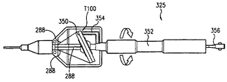
別の実施形態では、テンドン組立体403のまわりにニードル組立体401を巻き付ける代わりに、図16Bに示すように、反対に、ほぼ中央に位置決めされたニードル組立体401のまわりにテンドン組立体403が巻き付くように構成されてもよい。ニードル組立体401は軸方向スパインを有する構成部品である。ニードル組立体401が中心に位置決めされているので、ニードル438の経路長さはその中立位置に起因して変化しない。巻かれた組立体(ニードル組立体401およびテンドン組立体403)はテンドン436を引っ張ることにより発生されるモーメントを釣り合わせるのを助け、かくしてカテーテルシャフトの圧縮を釣り合わせるのを助ける。
In another embodiment, instead of wrapping the
別の実施形態では、テンドン組立体403およびニードル組立体401は互いのまわりに捩じられている。この実施形態は、1つの組立体が他の組立体より著しく剛性ではなくて、他の組立体を、曲りくねった解剖学的構造における存在が期待される領域におけるカテーテルの中心に置く場合に特に有用である。
In another embodiment,
以下の段落は、ニードル組立体401、テンドン組立体403およびカテーテルシャフト416の模範的な構成を詳細に論述するものである。
The following paragraphs discuss in detail exemplary configurations of the
ニードル組立体401はニードル438および低摩擦または潤滑性のニードルシース440を有している(図16A)。ニードル438は当業界で知られている在来のニードルであることができる。ニードル438はまっすぐな腔の直径を有するNiTi管で構成されることができる。ニードル438はステンレス鋼または他の金属合金、または編組補強ポリイミドのような剛性ポリマーで製造されることもできる。ニードルの遠位端部は、目標組織への刺込みまたは穿刺の容易のために尖端に勾配付けられている。ポリマーニードルでは、先端部はやはり、刺込みまたは穿刺の容易のために勾配付けられた金属構造体あることが好ましい。金属先端部およびポリマーボディは接着剤または他の適当な材料で互いに接合されることができる。一実施形態では、ニードル438の先端部は、送出し手順中、これが見えるために放射線不透過性物質を有する。放射線不透過性物質は、金、白金/イラニウム合金または他の適当な放射線不透過性物質によるめっきまたはコーティングのような方法を使用することによりニードル438の先端部に組み入れられることができる。ニードルシース440は、代表的には、潤滑性腔表面を有するポリマー(例えば、PTFEまたはTEFLON、HDPEまたは編組コイル補強ポリマー)のような低摩擦材料で製造されている。
テンドン組立体403はテンドンシース423内に配置されたテンドン436を備えている。一実施形態では、近位カテーテルシャフト416−Pに沿って、テンドンシース423は軸方向スパイン420である。遠位カテーテルシャフト416−Dに沿って、テンドンシース423は可撓性のテンドンシース421である。軸方向スパイン420は剛性であって、圧縮性ではないが、可撓性のテンドンシース421は可撓性であって、軟質である。シースの特性が異なる1つの理由は、テンドン436がトルクをカテーテル近位部分412に沿って伝達することが必要であり、かくしてテンドンシース423が剛性であって、圧縮性ではないことが必要であるからである。他方、テンドン436はカテーテル遠位部分414を撓ませることができる必要があり、かくしてテンドンシース423は基準の可撓性テンドンシース421により示されるように可撓性であることが必要である。
The
可撓性テンドンシース421は、代表的には、潤滑性腔表面を有するポリマー(例えば、PTFEまたはTEFLON、HDPE、潤滑性内層ポリマーを有する同時押出しポリマー、または編組コイル補強ポリマー)のような低摩擦材料で製造されている。軸方向スパイン420は、テンドン436が引っ張られてカテーテル遠位部分414を撓ませるときにカテーテルの圧縮を阻止する材料(例えば、ステンレス鋼またはニチノール)で製造されている。
The
別の実施形態では、テンドンシース423はカテーテルシャフト416の全長にわたって延びている可撓性テンドンシース421のみを有している。かくして、可撓性テンドンシース421は近位カテーテルシャフト416−Pのところで軸方向スパイン420に取って代わっている。可撓性テンドンシース421には、積み重ねコイル構造体425(図17)が近位カテーテルシャフト416−P内である部分に沿って設置されている。一実施形態では、積み重ねコイルテンドンシース425はステンレス鋼または他の金属合金のような金属製である。積み重ねコイルテンドンシース425は、テンドン436が引っ張られてカテーテル遠位部分414を撓ませるときにカテーテルの圧縮に対する抵抗を与えるために軸方向スパイン420と同様な機能をもたらす。
In another embodiment, the
また、テンドン組立体403は軸方向スパイン420の両端部に設けられた2組のスリップバンド424、426を有している(図16A)。スリップバンド424、426を有する軸方向スパイン420の端部はそれぞれ部分404および部分410として示されている。スリップバンド424、426はそれぞれ軸方向スパイン420を固定部材428、430に連結している。スリップバンド424、426は、固定部材428、430とともに、テンドン組立体403を適所に固定するように作用し、そしてテンドン436が引っ張られるとき、カテーテル近位部分412の長さを一定に保持するのを助ける。スリップバンド424、426は金属管、バンドまたはリングで製造されることができる。スリップバンドは、固定部材428、430からの材料が分散されて固定部材428、430へのスリップバンド424、426の接合を生じるように開口部を有している。
The
他の実施形態では、スリップバンド424、427なしで、スロットが軸方向スパイン420の壁部に切込まれることができ、固定部材428、430からの材料がこれらのスロットを通って分散されて軸方向スパイン420を固定部材428、430に固定するための締りロックを生じることができるようになっている。
In other embodiments, slots can be cut into the walls of the
以下の段落はカテーテル組立体400を構成する模範的な方法を詳細に説明している。 The following paragraphs describe in detail an exemplary method of constructing the catheter assembly 400.
図18から始めると、テンドン組立体403を作製する。スリップバンド424を端部420−Dに接合し、スリップバンド424を軸方向スパイン420の端部420−Pに接合する。一実施形態では、接着剤を使用してスリップバンド424、426を軸方向スパイン420に接合する。図19において、可撓性テンドンシース421を重なり部分498で軸方向スパイン420の遠位端部に連結する。一実施形態では、接着剤を重なり部分498のところで軸方向スパイン420とテンドンシース421との間に分配する。別の実施形態では、重なり部分498のところで開口部(図示せず)が可撓性テンドンシース421の中へ形成されてもよく、接着剤をこれらの開口部の中へ分配して軸方向スパイン420と可撓性テンドンシース421との間に接合を生じる。マンドレル(図示せず)を可撓性テンドンシース421の内腔に挿入して腔を次の熱工程において開いた状態に保つ。
Beginning with FIG. 18, a
次に、図20において、変化付け部材442および固定部材428を作製する。変化付け部材442および固定部材428は、(可撓性テンドンシース421および軸方向スパイン420を有する)テンドンシース423と、ニードルシース440とが埋設されて作製される。一実施形態では、変化付け部材442および固定部材428を形成するために押出し成形ポリマー管452が使用される。このポリマー管452は中央腔454を有している。ポリマー管452には、2つの開口部が僅かに長さ方向に間隔を隔てられた両側に形成されている。図20に示すように、第1開口部456および第2開口部458が形成され、互いに反対側に位置決めされている。図20において、スリップバンド424を有し、(図19に示されるように)テンドン組立体403用の可撓性テンドンシース421に重ね接合されている軸方向スパイン420を、部分404の長さにほぼ等しい距離をおいてポリマー管452の中央腔454に設置する。軸方向スパイン420が可撓性テンドンシース421の中で終わっている部分において、第1開口部456を通ってポリマー間452の外側に出るように可撓性テンドンシース421を移動させる。ニードル組立体401用であって、内腔を支持するマンドレル(図示せず)を有するニードルシース440を、スリップバンド424を有する部分(または部分404)を通るまでポリマー管452の外側に設置する。部分404の後、ニードルシース440を第2開口部458を経て中央腔454に入れる。テンドンシースおよびニードルシース440がそれらの適切な位置に設置された後、収縮管460を、管452を覆って設置する。次いで、収縮管460に熱を加える。管452からのポリマーが溶融すると、管の外側に設置された組立体は管452の壁部に没入するが、管452の中央腔に設置された組立体はほぼ中心に留まる。腔支持マンドレル(図示せず)は、熱融着法中、可撓性ニードルシース421およびニードルシース440の内径を開いた状態に保つ。これにより、固定部材428および変化付け部材442を形成する。
Next, in FIG. 20, the changing
次に、テンドン組立体403用のテンドンシース423およびニードル組立体401用にニードルシース440を互いのまわりに巻き付ける。図16に示すように、テンドンシース423およびニードルシース440は近位カテーテルシャフト416−P内である部分において互いのまわりに巻き付く。一実施形態では、ニードルシース440はテンドンシース423の軸方向スパイン420のまわりに巻き付けられる。
Next, the
次に、ニードル組立体401用にニードルシース440およびテンドン組立体403用のテンドンシース423を埋設するように、固定部材430が作製される。固定部材430は、開口部456と同様な開口部が必要とされない以外、固定部座愛428と同様に形成される。スリップバンド426を有する軸方向スパイン420を(腔454と同様な中央腔において)管452と同様なポリマー管の内側に設置する。ニードルシース440をポリマー管の外側に設置する。軸方向スパイン420およびニードルシース440がそれらの適切な位置に設置された後、収縮管を、ポリマー管を覆って設置する。次いで、熱を収縮管に加える。管からのポリマーが溶融すると、管の外側に設置された組立体が管の壁部に没入するが、管の中央腔に設置された組立体はほぼ中心に留まる。これにより、軸方向スパイン420およびニードルシース440が埋設された固定部材430を形成する。この時点で、カテーテルシャフト416用の内部構成部品が組み付けられる。
Next, the fixing
次に、近位コアシャフト418が図21に示すように作製される。近位コアシャフト418用の押出し成形管を用意する。マンドレル462を近位コアシャフト418用の押出し成形管の腔に挿入する。近位コアシャフト418の頂部に編組層417を押出し成形で設ける。ポリマー管464を、編組層417を覆って設置する。収縮管466を、ポリマー管464を覆って設置する。収縮管は近位カテーテルシャフト416−Pの外径を規定する。次いで、熱を収縮管466に加えてポリマー464を編組層417の中に融着する。熱融着法後、収縮管466および支持マンドレル462を取り出す。この時点で、近位カテーテルシャフト416−Pが作製され、これを図16Aで見ることもできる。
Next, the
次に、以上のように作製された内部構成部品組立体を近位シャフト416−Pに挿入して図16Aに示される構造体を得る。一実施形態では、接着剤または熱融着法を使用して内部構成部品組立体および近位カテーテルシャフト416−Pを両端部で互いに接合する。接着剤を使用する場合、近位シャフト416−Pを貫通して開口部(図示せず)を形成することができ、次いで、開口部を通して接着剤を分配して内部構成部品組立体と近位カテーテルシャフト416−Pとの間の空間に充填することができる。 Next, the internal component assembly produced as described above is inserted into the proximal shaft 416-P to obtain the structure shown in FIG. 16A. In one embodiment, an internal component assembly and proximal catheter shaft 416-P are joined together at both ends using an adhesive or heat-seal technique. If an adhesive is used, an opening (not shown) can be formed through the proximal shaft 416-P, and then the adhesive can be dispensed through the opening and proximal to the internal component assembly. The space between the catheter shaft 416-P can be filled.
次に、遠位カテーテルシャフト416−Dを作製する。図16Aに示すように、遠位カテーテルシャフト416−Dはその中にすぐのところに配置されて圧縮ケージ446を有している。一実施形態では、充填材448を使用して圧縮ケージ446の内側の空間を埋める(図23)。充填材448は可撓性テンドン組立体421およびニードルシース440を遠位カテーテルシャフト416−Dの適所に保持するために使用されている。例えば、充填材448は遠位カテーテルシャフト416−Dの中心を外れて可撓性テンドン組立体421を(従って、テンドン436を)保持するのを助ける。充填材448は変化付け部材442の形成と同じ工程で形成されることができる。一実施形態では、圧縮ケージ446は変化付け部材442に連結されているが、充填材部分への物理的取付け状態ではない。一実施形態では、充填材448はニードルシース440および可撓性テンドンシース421に物理的に融着される(取付けられる)。他の実施形態では、充填材448はカテーテル遠位部分414の端部間の中間部分においてニードルシース440および可撓性テンドンシース421に物理的に融着される(取付けられる)。僅かな分離により、カテーテル遠位部分414の追加の可撓性および移動自由度を与えており、そして撓み中のニードルシース440の物理的引張りを防ぐ。充填材448の遠位端部は、両実施形態では、先端アンカー444のすぐ近くで終わっている。また、充填材448を有することにより遠位カテーテルシャフト416−Dにおけるねじれを防ぐ。
Next, the distal catheter shaft 416-D is made. As shown in FIG. 16A, the distal catheter shaft 416-D has a
一実施形態では、ニードルシース440と可撓性テンドンシース421との間に、壁部468(図22)を設ける。この壁部468は遠位カテーテルシャフト416−Dの中心を外れてテンドン中心421を保持するために充填材の代わりに使用されてもよい。壁部468はPEEKまたはポリイミドのような可撓性NiTiリボン、ポリマーリボンで製造されることができる。壁部468の両端部は遠位カテーテルシャフト416−Dに内側構成部品に固定される。カテーテル遠位部分414の近位端部において、壁部468を可撓性テンドンシース421とニードルシース440との間において変化付け部材442内に閉じ込める。部分414の遠位端部において、リボンを遠位先端アンカー444の溝(図示せず)に閉じ込める。
In one embodiment, a wall 468 (FIG. 22) is provided between the
可撓性テンドンシース421およびニードルシース440がそれらの適切な位置に設置された後、ポリマー層を圧縮ケージ446に設ける。このポリマー層を覆って収縮管を設置する。次いで、熱をカテーテル遠位部分に加えてこれらの層を互いに融着して遠位カテーテルシャフト416−Dを完成する。一実施形態では、熱はポリマー層および圧縮ケージ446の遠位端部および近位端部に加えられるだけである。かくして、圧縮ケージ446の近位端部および遠位端部がポリマーに融着されて中間部分においてより可撓性の遠位カテーテルシャフト416−Dを得る。
After the
テンドン436をカテーテルシャフト416内に挿入する。テンドン436は、カテーテルシャフト416の内部構成部品すべてをカテーテルシャフト416に組み入れた後にカテーテルシャフト416に挿入されるだけである。例えば、接着剤、溶接、はんだ付け、クリンプ加工、機械的締めなどにより遠位先端アンカー444を圧縮ケージ446および遠位カテーテルシャフト416−Dに連結する。一実施形態では、遠位先端アンカー444はテンドンアンカーとして機能する。接着剤、溶接、はんだ付け、クリンプ加工、機械的締めまたは他の適当な技術によりテンドン436を遠位先端アンカー444の壁部に連結する。次いで、テンドン436をテンドンシース421に挿入し、そしてこれが近位カテーテルシャフト416−Pに達して近位カテーテルシャフト416−Pから延出するまで、軸方向スパイン420に近位方向に押し通す。
A
ニードル438をニードルシース440内に配置する。ニードル438はカテーテルシャフト416の遠位端部から近位カテーテルシャフト416−Pの外側まで延びる。例えば、接着剤を使用してニードルシース440の遠位端部を遠位先端アンカー444に接合することができる。
幾つかの実施形態では、生物学的薬剤の送出しと共に生理学的電気信号の検出のための或る治療手順が望まれる。これらの実施形態では、遠位先端アンカー444はカテーテル組立体100において述べたものと同様な先端電極に変換されることができる。先に述べたカテーテル組立体100と同様な先端電極に対して2、3ミリメートル近位方向の位置に追加のバンド電極を追加することができる。両方の電極を有することにより、近範囲二極信号を感知し、それによりノイズ対信号の比を大いに減少させる。電極からの導体ワイヤがカテーテルシャフト内に延びている。中央の構成部品(テンドンシースまたはニードルシース)のまわりへのこれらのワイヤの巻き付けは有利であるが、必ずしも必要ではない。ワイヤのサイズによっては、これらのワイヤの質量は、回転問題を防ぐためにテンドン組立体403またはニードル組立体401のまわりに巻き付けられる必要がないほどに小さくてもよい。
In some embodiments, certain therapeutic procedures for the detection of physiological electrical signals as well as the delivery of biological agents are desired. In these embodiments,
心室に治療器具を使用する手順では、カテーテルの送出しを案内することができることにより、投与量の精度を多いに改良する。MRIはカテーテル組立体400と同様なカテーテル組立体を案内するための1つの選択肢である。カテーテル組立体400は、その鉄(例えば、ステンレス鋼)材料を非鉄だが機能化材料と置き換えることによりMRIスキャナと適合性にされることができる。一実施形態では、テンドン436は冷間加工条件においてNiTiと置き換えられる。他の実施形態では、編組層417はナイロンリボンにより置き換えられ、スリップバンド424、426は軸方向スパイン42に切込まれたスロットまたは白金のような材料で置き換えられる。
The procedure of using a therapeutic instrument in the ventricle greatly improves dosage accuracy by being able to guide the delivery of the catheter. MRI is one option for guiding a catheter assembly similar to catheter assembly 400. The catheter assembly 400 can be made compatible with an MRI scanner by replacing its ferrous (eg, stainless steel) material with a non-ferrous but functionalized material. In one embodiment,
上述のカテーテル組立体400は、非対称に位置決めされた構成部品およびニードル経路の長さの変化により発生されるモーメントおよびニードル経路の長さの釣り合いについての多数の利点をもたらす。この結果、カテーテルの優れた回転応答性および正確なニードルの伸張の制御が得られる。 The catheter assembly 400 described above provides a number of advantages for asymmetrically positioned components and the balance of the moment and needle path length generated by the change in needle path length. This results in excellent rotational response of the catheter and precise needle extension control.
幾つかの用途では、撓み可能なカテーテル組立体100または撓み可能なカテーテル組立体400のような撓み可能なカテーテル組立体の可変の撓み長さが極めて有用である。固定された撓み長さは、患者の心室における誘導のような患者内でカテーテル組立体を誘導することをより困難にすることがある。例えば、カテーテル組立体の長い撓み先端部は心室コードと容易に縺れることがある。更に、カテーテル組立体が大動脈弁を通って弁室に入ると、注入のためにカテーテル組立体の長い撓み先端部を隣接した隔膜壁部に向けて回転させるのが非常に困難であることがある。従って、このような状況中、より短い撓み先端部を設けること、および横方向壁部のような遠い領域を目標とする場合、より長い撓み線端部で、より容易な接近および支持を行うことが有用である。かくして、カテーテル組立体100またはカテーテル組立体400のようなカテーテル組立体に種々の撓み長さを有する撓み可能な先端部を備えることが有利である。
In some applications, the variable deflection length of a deflectable catheter assembly such as
図24は先に述べたカテーテル組立体100または400と同様な構成を有する撓み可能なカテーテル組立体を示している。一般に、カテーテル組立体344は、これが撓み変化箇所348で始まって撓み可能であるカテーテル遠位部分346を有すると言う点でカテーテル組立体100または400と同様である。カテーテル組立体100または400と同様に、カテーテル組立体344もまた、カテーテル近位部分347を有しており、このカテーテル近位部分347は更に、注入ポート345を有してもよい取っ手200に連結されている。内部構成部品(例えば、テンドン組立体およびニードル組立体または複数のニードル組立体)はカテーテル組立体100または400と同様に構成されている。カテーテル組立体344に与えられる1つの問題は可変または調整可能な撓み長さである。
FIG. 24 shows a deflectable catheter assembly having a configuration similar to the
可変の撓み長さを有さない撓み可能なカテーテル組立体では、テンドン(例えば、テンドン130またはテンドン436)を引っ張ることにより、カテーテル組立体の端部をテンドンの円意ハーネスから引っ張ってカテーテルの遠位軟質部分をシャフト変化点から撓ませる。撓ませテンドンが先端部から(例えば、遠意アンカー444または140から)固定長さのところで溶接されるか、固定されるか、或いはハーネス留めされており、且つカテーテル組立体の可撓性部分もまた固定長さのものであるので、カテーテルはただ単一の点から撓められて固定長さの撓み部分を生じることができる。従って、欠陥である変更不可能な撓み長さを有する各カテーテル組立体が生じられる。
In a deflectable catheter assembly that does not have a variable deflection length, the end of the catheter assembly is pulled from the tendon circular harness by pulling on a tendon (eg,
一実施形態では、可変の撓み長さを有するカテーテル組立体344はカテーテル遠位部分346の可撓性長さを変えることによって達成される。図25に示すように、カテーテル遠位部分346は少なくとも撓み長さ341、343を有している。可変の撓み長さはカテーテル遠位部分346に沿って撓み変化点を移動させるか、或いは可撓性長さを短くすることによって得られることができる。一実施形態では、カテーテル組立体344は撓み変化点348から始まる最大の撓み長さを有しており、この最大の撓み長さはカテーテル組立体344用に予め設定されている。また、撓み変化点348はカテーテル組立体344に固定された永久の変化点を定める。一実施形態では、撓み長さは、図25に示すように、撓み変化点348を撓み変化点358まで移動させることによって変えられる。一実施形態では、撓み変化点348と撓み変化点358との間の部分であるカテーテル遠位部分346に沿った部分360はより剛性にされている。かくして、カテーテル遠位部分346は、部分360がより剛性であるので、(撓み変化点348ではなく)撓み変化点358のところで撓み始める。
In one embodiment, the
図26A−Bはカテーテル組立体344に組み入れられることができる模範的な剛性化構成部品363を示している。剛性化構成部品363は剛性化部材362に繋がっているプッシュワイヤ364を備えている。撓みのために有効な可撓性カテーテル遠位部分346の長さは、剛性化構成部品363をカテーテル遠位部分内腔に沿って摺動させてカテーテル遠位部分346の一部(例えば、部分360)をより剛性にして撓み不可能にすることによって操られることができる。これにより新しい撓み変化点、例えば、撓み変化点358を生じる。
FIGS. 26A-B illustrate an
一実施形態では、剛性化構成部品363はテンドン組立体を収容する腔と平行に延びている腔内に配置されている。プッシュワイヤ364はカテーテルシャフトを通って延びており、そして剛性化構成部品363の移動を制御するために取っ手200内に含まれてもよい制御機構により延長されている。剛性化部材362は、撓みテンドンの緊張により、剛性化部材362に対して遠位の領域においてのみカテーテルの撓みを生じるように、可撓性カテーテル遠位部分346より剛性である。カテーテル組立体344の遠位端部に対する剛性化部材362の位置を変えることにより、撓み可能なカテーテル遠位部分346の長さを間接的に変える。図26Bに示すように、剛性化構成部品363はテンドン組立体(図示せず)と平行に延びている腔内に配置されており、剛性化構成部品363が剛性化部材362をカテーテル遠位部分346の部分360の中へ移動させると、撓み変化点348はもはや、カテーテル遠位部分346の撓みが始まる点ではない。その代わり、撓み変化点358が、カテーテル遠位部分346の撓みが始まる点になる。剛性化構成部品363は、カテーテル346に可変の撓み長さを備えさせるために、撓み変化点348に対して遠位であるカテーテル遠位部分346に沿って種々の位置まで移動され得る。
In one embodiment, the
図26A−26Bに示すように、剛性化構成部品363は剛性の大きい遠位部分、剛性化部材362を有している。剛性化部材362はカテーテル遠位部分346に沿って剛性部分を生じるのに十分である所望の長さ、例えば、約1ないし7cmの長さを有してもよい。剛性化部材362は、ステンレス鋼のような材料、またはリベット部分用のステンレス鋼およびプッシュワイヤ364用の複合ポリマー材料(例えば、補強ポリイミド)のような材料の組み合わせで製造されてもよい。プッシュワイヤ364は操向可能なカテーテル組立体344のシャフトの剛性またはモーメントの釣り合いを変えないように十分に可撓性である。プッシュワイヤ364はこれと腔との間の摩擦を減少させるために潤滑性被覆材(例えば、テフロン、シリコーンなど)で被覆されてもよい。プッシュワイヤ364はカテーテル組立体344の近位端部まで延びるのに十分に長く、そして制御移動可能に近位取っ手00により制御され得る。一実施形態では、剛性化構成部品363を収容する腔は、シャフト横断面を横切るモーメントの釣り合いを変えないように、非撓み性部分(カテーテル近位部分347)における反対側腔とほぼ同じである。遠位方向では、腔は、効果的な剛性を達成する必要のために、より大きい剛性化部材362を受入れるためにより大きくなってもよい。
As shown in FIGS. 26A-26B, the
図26Cはカテーテル組立体344の他の腔に対する剛性化構成部品363の模範的な構成を示すカテーテル近位部分347の横断面を示している。カテーテル組立体100または400と同様に、カテーテル組立体344は幾つかの腔370、378、374、382を有している。腔370は(例えば、ニードル組立体109と同様な)ニードル組立体372を受け入れことができ、腔378は(例えば、ニードル組立体105と同様な)他のニードル組立体380、または単に腔充填材を受入れることができる。腔374は(例えば、テンドン組立体103と同様な) テンドン組立体376を受入れることができる。かくして、腔382は剛性化構成部品363を受入れる。
FIG. 26C shows a cross-section of the catheter
別の実施形態では、剛性遠位部分を有する外側シースがカテーテル組立体344を覆って配置されてカテーテル組立体344に可変の撓み長さをもたらしている。この実施形態では、外側シースは剛性化構成部品363に取って代わっている。
In another embodiment, an outer sheath having a rigid distal portion is disposed over the
図27Aに示すように、外側シース385が設けられている。この外側シース384は可撓性部分386および剛性化部分388を有している。外側シース384はカテーテル組立体344の外側に配置されている。かくして、外側シース384はカテーテル組立体344の外径にわたって延びている。カテーテル遠位部分346に沿った剛性化部分388の位置はカテーテル組立体344の撓み変化点を変化させる。図27Bに示すように、外側シース384が元のシャフト変化点348を通って前進され、次いで、カテーテル組立体のテンドンが引っ張られ、カテーテルが剛性化部分388に対して遠位の位置で撓む。この部分を操向可能なカテーテル組立体の可撓性の撓み可能な領域の中へ前進させることにより、この領域における剛性は増大する。この結果、撓み点が外側シースに対して遠位の位置へ変化する。一実施形態では、可撓性部分384はカテーテル組立体344の近位端部からの外側シースの制御移動を許容するのに十分にまさに剛性に製造されている。
As shown in FIG. 27A, an outer sheath 385 is provided. The
外側シース384は、長さ方向に移動自由であるように、操向可能なカテーテル344にわたる小さいまたは最小の間隔と合うように製造されている。外側シース384は編組ステンレス鋼層で補強された異なるジュロメータのポリマーで構成されてもよい。異なる剛性は編みパターンならびにポリマーのジュロメータを変えることにより達成され得る。剛性化部分388はカテーテル遠位部分346に沿って剛性部分を生じるのに十分である所望の長さ、例えば、約1ないし7cmの長さを有してもよい。剛性化部分388は、より大きい剛性以外、可撓性部分386と同様に構成されてもよい。剛性化部分388および可撓性部分386は、カテーテルシャフトを製造するのに代表的に使用されている材料から構成されてもよい。剛性化部分388は蜜に編祖されたステンレス鋼で補強された高いジュロメータの材料で構成されることができる。可撓性部分386はカテーテルシャフト101(カテーテル組立体100)または416(カテーテル組立体400)を製造するのに使用されているものと同様な低いジュロメータの材料で構成されてもよい。
The
他の実施形態では、可撓性部分386は、図28A−28Cに示すように、完全な管ではないが、部分管386−P(例えば、三日月形横断面を有する管)である。図28Aに示すように、カテーテル組立体344は取っ手200に連結されている。カテーテル組立体344の外側には、剛性化部材388が配置されている。この剛性化部材388は管である。剛性化部材388には、部分管386−Pが取り付けられている。剛性化部材388および部分管386−Pの両方はカテーテル組立体344のカテーテルシャフトに沿って移動可能である。しかしながら、剛性化部材388は取っ手200上で摺動することができないように構成されている。一実施形態では、剛性化部材388は、これが取っ手200から離れる方向に摺動しないように停止されるように取っ手00の円意端部と係合する干渉特徴388−Eを有している(図28C)。他方、部分管386−Pは図28Bに示すように取っ手200上で摺動することができる。この実施形態では、剛性化部材388は、使用中でないとき、血管系から引き出されることができる。
In other embodiments, the
更に他の実施形態では、図29A−29Bに示すように、剛性化構成部品390が外側シース384に取って代わっている。剛性化構成部品390は剛性化シース392およびプッシュシャフト394を有している。プッシュシャフト394は、剛性化シース392に取付けられることができ、そして剛性化シース392をカテーテル組立体344のカテーテルシャフトに沿って移動可能に摺動させることができるワイヤから製造されることができる。剛性化シース392の前進または後退はプッシュシャフト394により制御される。プッシュシャフト394は取っ手200の外側に設置されている。図29A−29Bに示される構成によれば、使用されていないとき、剛性化シーsジュ392を血管系の外側に引き出すことができる。
In yet another embodiment, the
図30A−30Bは可変の撓み形状または湾曲を有する他のカテーテル組立体501を示している。このカテーテル組立体501は先に述べたカテーテル組立体100または400と同様である。一般に、カテーテル組立体501は撓み変化点538のところで始まって撓み可能であるカテーテル遠位部分536を有している。カテーテル組立体100または400と同様に、カテーテル組立体501はまたカテーテル近位部分534を有しており、このカテーテル近位部分534は、更に、注入ポート510および撓みつまみ506を有してもよい取っ手200に連結されている。内部構成部品(例えば、テンドン組立体およびニードル組立体)はカテーテル組立体100または400のものと同様に構成されている。カテーテル組立体501に与えられる1つの問題は可変または調整可能な撓み形状または湾曲である。
30A-30B illustrate another
カテーテル組立体501は二重テンドン装置を有しており、この二重テンドン装置は互いに平行に且つ極めて近接して設置された第1テンドン(または横方向テンドン)組立体540および第2テンドン(または固定テンドン)組立体542を有している。テンドン組立体540、542の各々はカテーテルシャフト544内の腔内に配置されている。横方向テンドン組立体540は第1テンドン546を有しており、この第1テンドン546はその遠位部分に連結されたテンドンフック548を有している。テンドンフック548は横方向テンドン組立体540が存在する腔の外側で延びている。固定テンドン組立体542は第2テンドン550を有しており、この第2テンドン550はその一部に沿って設置された複数のテンドンアンカー552を有している。これらの複数のテンドンアンカー552は固定テンドン組立体542が存在する腔の外側で延びている。
固定テンドン組立体542はカテーテルシャフト544の腔内に配置されている。カテーテル近位ブブン4において、固定テンドン組立体542を収容する腔はカテーテルシャフト544の全長全体にわたってカテーテルシャフト544の中心を外れて位置決めされている。第2テンドン550は遠位先端部のところでカテーテル組立体501の遠位先端部に固定されている。
横方向テンドン組立体540はカテーテルシャフト544の他の腔内に配置されていて、固定テンドン組立体542と平行に延びている。横方向テンドン組立体540を収容する腔はカテーテル近位部分534に沿ってカテーテルシャフト544の中心に或いはほぼ中心に位置決めされている。横方向テンドン組立体540を収容する腔はカテーテル遠位部分536に沿ってカテーテルシャフト544に中心を外れて位置決めされている。横方向テンドン組立体540は固定テンドン組立体542に沿って移動可能または摺動可能である。
カテーテルシャフト544の撓み点538はカテーテル近位部分534とカテーテル遠位部分536との間の変化点である。撓みの端部は横方向テンドン組立体540が終わる点である。オペレータが横方向テンドン組立体540を引っ張ると、カテーテル遠位部分536が、例えば、図38Bに示すように撓み点538のところで撓み始める。また、横方向テンドン組立体540を移動させることにより、テンドンフック548をアンカー552のうちの1つに位置決めする。第1テンドン上のフック548は第2テンドンに位置決めされたアンカー552のうちの1つに係合する。この係合が起こる時点で、横方向テンドン組立体540が終わり、そして撓み部分が終わる。例えば、図30Bに示すように、テンドンフック548が(遠位端部から)第2アンカーに係合すると、カテーテル遠位部分536の撓みが撓み展38のところで始まるが、点538Bのところで終わる。点538Bに対して遠位の部分はまっすぐで撓まれていないままである。何故なら、横方向テンドン組立体540がこの部分に引っ張られていないからである。他の例では、図30Cに示すように、テンドンフック548が(遠位端部から)第4アンカー552に係合すると、カテーテル遠位部分536の撓みが撓み点538のところで始まるが、点538Cのところで終わる。点538Cに対して遠位の部分はまっすぐで撓まれていないままである。何故なら、横方向テンドン組立体540がこの部分に引っ張られていないからである。更に他の例では、図30Dに示すように、テンドンフック548が(遠位端部から)第5アンカー552に係合すると、カテーテル遠位部分536の撓みが撓み点538のところで始まるが、点538Dのところで終わる。点538Dに対して遠位の部分はまっすぐで撓まれていないままである。何故なら、横方向テンドン組立体540がこの部分に引っ張られていないからである。わかるように、テンドンフック548と複数のアンカー552との種々の係合点により、カテーテルシャフトの撓みの形状および湾曲を変化させることができる。
The
かくして、カテーテルシャフト544は、今までどおり、可撓性遠位部分および剛性近位部分534を有している。遠位部分と近位部分との間の変化点は撓み、曲線の始まりを定める。撓み曲線は、テンドンフック548がアンカー552に係合する点で終わる。この係合点に対して遠位のカテーテルシャフト部分はまっすぐで、撓み曲線の端部に対して接線方向に延びている。
Thus, the
別の実施形態では、横方向テンドン組立体540はこれが発生する圧縮荷重を釣り合わせるために固定テンドン組立体542のまわりに巻き付いてもよい。また、圧縮力を吸収する唯一の構成部品である固定テンドン組立体542は、他の実施形態において先に述べたように軸方向スパインの仕事をして圧縮に抵抗するように剛性に製造されるべきである。
In another embodiment, the
別の実施形態では、カテーテルシャフトを釣り合わせるために、追加の腔がカテーテルシャフト544に設けられている。少なくとも2つの追加の腔(図示せず)が設けられてもよく、そのうちの一方はこれを通して配置される治療器具(例えば、ニードル)に専用されることができる。残りの腔はカテーテルシャフト544を釣り合わせるのを助ける腔充填材が満たされてもよい。
In another embodiment, additional cavities are provided in the
一実施形態では、カテーテル遠位部分536は、可変の撓み形状および/または湾曲をもたらすために、フック548がテンドン550に沿って摺動してアンカー552のうちの1つに係合するための十分な隙間を許容するように全体的に融着されるわけではない。一実施形態では、図30A−30Dに示すように、アンカー552は、カテーテル組立体501の撓みを許容するために引き戻されるときにフック548を固定するのに役立つ低設置スパイクである。アンカー552の低設置スパイク特徴によれば、フック548はアンカー552上で容易に摺動してテンドン550に沿って遠位方向に移動し得る。フック548が所望のアンカー552まで移動されたら、横方向テンドン540を引っ張ることによりフック548をアンカー552に係合させる。この時点で、また、横方向テンドン540を引っ張ることにより、カテーテル遠位部分536の撓みを引起こし、この撓みはアンカー552がフック548に係合する時点で終わる。フック548は、(例えば、近位取っ手200を介して)横方向テンドン組立体540まで近位方向に操ることにより、アンカー552から解放される。フック548は、カテーテル遠位部分536の撓み終了点が変化されることができるようにアンカー552から解放される。フック548はC状部材を生じるように切り抜かれた部分を有する「C形状」リングであってもよい。横方向テンドン540を回転させることにより、C形状リングの開口部分を回転させてアンカー552と整合状態にし、かくしてアンカー552から外れるフック548の後退を容易にし得る。
In one embodiment, the catheter
図31−34、図35A−35H,図36A−36Bおよび図37A−37Bは、先に述べた或いはここに記載のカテーテル組立体100、400、344または501のようなカテーテル組立体に組み入れられることができる電極装置の模範的な具体例を示している。これらの図において、電極装置は、この開示に述べられているカテーテル組立体のうちのいずれかであることができるカテーテル組立体500に組み入れられている。このカテーテル組立体500は先に述べたカテーテル組立体100、344、400または501と同様である。一般に、カテーテル組立体500は、これが撓み変化点558のところで始まって撓み可能であるカテーテル遠位部分554を有していると言う点でカテーテル組立体100、344、400または501と同様である。カテーテル組立体100、344、400または501と同様に、カテーテル組立体500もまた、カテーテル近位部分556を有しており、このカテーテル近位部分556は更に、注入ポート510および撓みつまみ506を有してもよい取っ手200に連結されている。内部構成部品(例えば、テンドン組立体およびニードル組立体)は先に述べたカテーテル組立体、例えば、カテーテル組立体100または400のものと同様に構成されている。カテーテル組立体500は二極性電極装置を有しており、この二極性電極装置は先端電極504と、少なくとも1つの追加の電極バンド505とを有している。
31-34, 35A-35H, 36A-36B, and 37A-37B are incorporated into a catheter assembly such as the
電極装置は、心臓の室において、ヒズチジン束またはAV節の信号のような所望の局部的心臓信号を検索して得たり、カテーテル組立体500が治療生物学的薬剤を対応する位置へ送出すのを助けたりするために使用されることができる。カテーテル組立体500のための治療用途の例は、生物学的剤(遺伝子、蛋白質など)を欠陥のある心臓節または束に送出して生物ペーサを展開することである。他の例は、電極装置を使用して左心室の心筋層における梗塞帯域を探し出し、そして治療剤を同位置へ送出すことである。
The electrode device may retrieve and obtain a desired local cardiac signal, such as a histidine bundle or AV nodal signal, in the heart chamber, or the
カテーテル装置は治療薬剤を目標の心臓信号が検出される位置へ正確に送出すように設計されている。一般に、これらの信号は低い振幅を有する。従って、ノイズを信号比に低減し、且つ信号を局部的に或いは全体的に感知することができることが必要である。このカテーテル装置は所望の心臓信号をマッピングするための2極性電極を使用している。これらの2極性電極は2つの金属電極をカテーテルに互いに近接して設けることにより構成されている。一方の電極から感知された信号は他方の電極のための基本基準として使用される。しかしながら、遠視野信号が必要とされるなら、2極性設計を単極性設計に容易に変換することができることを心に留めておく。2極性電極は、これらが記録機に接続される途中で2つの単極性電極として使用されてもよい。 The catheter device is designed to accurately deliver the therapeutic agent to the location where the target cardiac signal is detected. In general, these signals have a low amplitude. It is therefore necessary to be able to reduce noise to signal ratio and to sense the signal locally or globally. This catheter device uses bipolar electrodes to map the desired cardiac signal. These bipolar electrodes are constructed by providing two metal electrodes close to each other on the catheter. The signal sensed from one electrode is used as the basic reference for the other electrode. However, keep in mind that if a far-field signal is required, a bipolar design can be easily converted to a unipolar design. Bipolar electrodes may be used as two unipolar electrodes while they are connected to the recorder.
一実施形態では、先端電極504およびバンド電極505は互いから2cm(他の実施の形態では、0.5cmないし2cm)間隔を隔てられることができ、それらの一方は図31に示すようにカテーテル組立体500の先端部に位置決めされている。これらの電極は導電性の絶縁されたワイヤ514(図32−33)および524(図35A−35H)に独立して接続されている。電極ワイヤ514、524の各々はカテーテルの壁部内で近位端部まで延びており、この近位端部から、心臓記録機(図示せず)差し込まれている電気ケーブルコネクタ508に取付けられている。
In one embodiment, the
図32−34は電極装置の設計のための異なる実施形態を示している。すべての設計において、先端電極504はカテーテルシャフトの内腔に接着されても、熱融着されてもよい。この取付けはシーソーまたはかかり付け表面特徴のような粗い表面組織を電極504のステムに設計することにより強化されてもよい。粗い組織は電極とカテーテルシャフトとの付着または結合を高める。電極は白金または金のような任意の生物学的適合性の導電性金属合金で製造されてもよい。また、電極は、MRIスキャナの内側にカテーテルを使用することができるように非強磁性組成を有する材料で製造されてもよい。
Figures 32-34 show different embodiments for electrode device design. In all designs, the
図32において、先端電極504は中心ニードル腔520のまわりに位置決めされている。電極504は下記の物理的形状:すなわち、丸い、丸くない、湾曲または平らな先端表面、または薄いリング設計のうちのいずれかであることができる。先端電極504は中心ニードル腔520の上方に位置決めされている開口部560を有している。ニードル512が開口部560から出ている。この先端電極504は、同様な信号振幅が測定された状態で、電極504の側部562および先端部564の両方において心臓の壁部に接触し得る。図32に示される実施形態は、心臓マッピングの点から見て最も使用し易い。一実施形態では、カテーテル組立体500の配向はフルオロスコープ技術を使用して視覚化され得、かくして目標部位へのニードル512の注入のために必要であることがあるカテーテルの配向の正確な決定を行なえる。
In FIG. 32, the
幾つかの用途では、目標信号の検出はカテーテルの配向のいずれの指示をも示さない。幾つかの病気発生では、伸張しているニードル512が心臓の壁部に接触しないように、カテーテルが心臓の壁部と平行に位置してもよい。図33は配向検出問題に取り組むように設計された他の先端電極504を示している。この先端電極504は図33に示すように先端面564のところで露出されているだけである。露出先端部564が目標の帯域に触れると、信号の振幅が最も大きくなる。カテーテル組立体500は壁部に対してほとんど垂直に配向される。従って、図33に示される先端電極504の具体例によれば、カテーテル先端部の配向を良好に確認し得る。所望の信号が検出されると、カテーテル先端部は、恐らく、心臓壁部とのニードル512の接触を容易にするように配向される。
In some applications, detection of the target signal does not indicate any indication of catheter orientation. In some disease occurrences, the catheter may be positioned parallel to the heart wall so that the extending
幾つかの他の用途では、カテーテルが壁部に対して垂直になるのに十分な余裕がないように目標の位置が密な間隔内である。1つの例は右弁室の弁膜の背後の隔壁部である。間隔は密であるので、カテーテルは側方に位置するはずである。カテーテル組立体500の先端部からのニードルの伸張は隔壁部である目標に達しない。図34において、ニードル512はカテーテル組立体500のカテーテルシャフトの側面における先端電極504から出ている。この実施形態では、先端電極504はニードル512がカテーテル組立体500から出ている側である側面566において露出されているだけである。
In some other applications, the target locations are within close spacing so that there is not enough room for the catheter to be perpendicular to the wall. One example is a septum behind the leaflet of the right valve chamber. Since the spacing is tight, the catheter should be lateral. The extension of the needle from the distal end of the
一実施形態では、ニードル512が曲線568を通って移動するときにニードル512がカテーテル壁部を貫通するのを防ぐために、ニードル512を特に曲線568に沿って収容する腔の外径にデフレクタリボン502が設けられている。
In one embodiment, to prevent
デフレクタリボン502はステンレス鋼、ニチノールまたは他の金属合金のような金属材料で製造されることができる。リボン502は曲がり曲線の長さに及ぶ長さにわたってニードル腔520の内面に設置されている。リボン502の近位端部は固定されていて、腔520のポリマー内に埋め込まれることができる。ニードル512は、最も恐らく、その先端部が常にリボン502の近位端部に対して遠位方向に位置決めされるようにして設置される。従って、ニードル512を前進させても、リボン502の近位端部に引っ掛からない。リボン502の遠位端部は、例えば、接着剤を使用することによって腔520に固定されることができる。ニードルの先端部が移動して通るリボン502の長さにわたって、リボンが腔の表面上に露出される。また、リボン502は、ニードルの先端部が常にリボン502の表面に載っているようにニードル512の外径よりわずかに幅広く製造されている。ニードル先端部が曲がり領域を通って遠位方向に前進されると、鋭い勾配付き先端部は曲がり領域の湾曲に接する方向に腔壁部上を摺動する傾向がある。リボン502無しでは、ニードル512は最も恐らくニードル腔壁部を構成するポリマーに刺し入る。リボン502が存在すると、ニードル先端部は湾曲壁部に刺し入るのが防がれるが、むしろ、湾曲壁部を辿って先端部の側面においてカテーテルから出る。一実施形態では、ニードル512がカテーテル組立体500から出ている側面566は壁部または目標部位に接触するカテーテルシャフトの側面である。この側面でのみ先端電極を露出させることにより、カテーテル組立体500の配向の高められた感度および正確な決定を見込め、それによりニードル512が目標部位に侵入するのを容易にする。更に、図34に示される実施の形態によっても、カテーテル組立体500は、注入中、動いている心臓の壁部に安定に寄りかかることができる。
The
一実施形態では、図35A−35Bに示すように、バンド電極505は先端電極504に近接して、例えば、2cm以内(または0.5ないし2cm以内)先端電極504に近接して位置決めされている。バンド電極505で感知された信号は先端電極504の信号のための基準として使用される。目標信号源の振幅および目標源のまわりのノイズ信号によっては、2つの電極間の距離は最適の性能のために変化してもよい。源信号の振幅が低ければ低いほど、および必要とされる信号対ノイズの比が高ければ高いほど、2つの電極間の必要とされる距離は短くなる。
In one embodiment, as shown in FIGS. 35A-35B, the
バンド電極505は幾つかの方法で構成されることができる。バンド電極505はカテーテルシャフトの壁部内に延びている導電性ワイヤ524に接続された金属バンドであることができる。バンド電極505はカテーテル組立体500のカテーテルシャフトの内壁部に接着されるか或いは熱融着されている。このバンド電極が導電性であるために、バンド電極505の少なくとも一部が血液貯留部に露出されなければならない。バンド電極505はカテーテルシャフトの外壁部に設置されてもよいし、或いは付着されてもよい(図35A)。変更例として、バンド電極505はカテーテルシャフトに組み入れられてもよい(図35B)。従って、カテーテルシャフト上のポリマーが融着方法からバンド電極505を覆うなら、開口部522(図35B)が覆い層を貫通して形成されてバンド電極505を露出させる。変更例として、バンド電極505を形成するのに導電性コイルまたは導電性ワイヤの巻く付けを使用してもよい。コイルまたは巻き付けられたワイヤは金属バンドよりも可撓性である。
The
別の実施形態では、電極装置は先端アンカー(例えば、カテーテル組立体100の先端アンカー140またはカテーテル組立体400の先端アンカー444)に組み入れられている。図35C−35Fはこのような模範的な具体例を示している。
In another embodiment, the electrode device is incorporated into a distal anchor (eg,
図35Cは先端アンカー/電極部材580へのテンドン526、導電性ワイヤ513およびニードル512の取付けを示している。先端アンカー/電極部材580は、アンカーに対するカテーテルシャフトのテンドンおよびニードル組立体のための設置部ならびにカテーテルシャフトのための電極装置の両方として機能するので、そのように称される。先端アンカー/電極部材580は溝581および溝582を有している。導電性ワイヤ513は溝581の中にはんだ付けされており、テンドン526は溝582の中にはんだ付けされている。溝581、582は180度離れている必要がないが、図35Cには、このように示されている。先端アンカー/電極部材580の中央腔84には、ニードルシース583が接着されている。このニードルシース583はニードル512を先端アンカー/電極部材580から電気的に絶縁している。
FIG. 35C shows the attachment of
一実施形態では、先端アンカー/電極部材580に対するテンドン526および導電性ワイヤ513のはんだ接合部の接合強度を増大するために、機械的係止構造体が溝581または528に設けられている。一実施形態では、溝582の遠位部分は溝582の近位部分より幅広い。テンドン526の取付けのために、テンドン526の先端部が平坦化されて幅広い溝部分に嵌る幅広い部分526−Wを生じ、テンドン526の非平坦化の幅狭い部分526−Nは溝582の幅狭い部分に嵌る。はんだが溶融されて溝582のギャップを埋めてテンドン526を溝582に固着する。これは図35Dに示されている。導電性ワイヤ513については、絶縁材513−Tが導電性ワイヤ513の遠位端部から取り去られる。導電性ワイヤ513の先端部分513−Tが溝581の幅広い部分内にカールされる。はんだが溶融されて溝581のギャップを埋めて導電性ワイヤ513を溝の内側に保持する。これは図35Eに示されている。
In one embodiment, a mechanical locking structure is provided in
図35Fはカテーテル組立体100、400または500のようなカテーテル組立体における先端アンカー/電極部材580の組付け詳細を示している。先端アンカー/電極部材580は圧縮ケージ585の遠位端部にあって、遠位カテーテルシャフトの充填材586に対して遠位方向に、しかし必要ではないが撓みのより自由度のために物理的接触して位置決めされている。先端アンカー/電極部材580の小径部分であるステムは接着またははんだ付けのような技術を使用することにより圧縮ケージ585に連結されている。遠位ジャケット587およびテンドン526は先端アンカー/電極部材580をカテーテル内に保持するのを助けている。ステンレス鋼または白金合金のような金属材料で製造された捕獲バンド588が先端アンカー/電極部材580上にはんだ付けされるか或いは接着されてはんだ付けされたテンドン526および導電性ワイヤ513を覆っている。ポリマー製の遠位外側ジャケット587が、先端アンカー/電極部材580および圧縮ケージ585の遠位端部と重なっている部分に融着されている。
FIG. 35F shows the assembly details of the distal anchor /
幾つかの実施形態では、カテーテル組立体500は前述のように圧縮ケージ585を有している。このような実施形態では、バンド電極505を図35Cに示すように圧縮ケージ585に対して遠位方向に(またはすぐ遠位方向に)、或いは変更例として、図45Hに示すように圧縮ケージ585に対して近位方向に(またはすぐ近位方向に)設置することが有利であることがある。これにより、バンド電極505および関連された導電性ワイヤ524をカテーテル組立体500に組み入れるのを容易にしている。
In some embodiments, the
図36A−36Bおよび図37A−37Bはカテーテル組立体500のテンドン組立体およびニードル組立体に対する導電性ワイヤ514、524の位置の模範的な具体例を示している。図36Aでは、ニードル512は中央腔520に位置決めされており、テンドン526は中心を外れた腔570に位置決めされており、導電性ワイヤ514は中心を外れた腔572に位置決めされており、導電性ワイヤ524は他の中心を外れた腔574に位置決めされている。カテーテル組立体500のカテーテルシャフト内の空の空間はポリマー充填材528で埋められ、そして前述のカテーテル組立体、例えば、カテーテル組立体100または400と同様な編組層518で支持されてもよい。
36A-36B and FIGS. 37A-37B show exemplary implementations of the positions of the
図36Bでは、ニードル512は中心を外れた腔520に位置決めされている。ニードル512は、テンドン526が前述の、例えば、カテーテル組立体100または400と同様に中心に位置決めされているカテーテル近位部分556に中心を外れて位置決めされてもよい。
In FIG. 36B,
図37Aでは、カテーテルシャフトは中空の腔576を有している。カテーテル組立体500の内部構成部品のすべて、例えば、ニードル組立体、テンドン組立体および導電性ワイヤは、すべて、中空の腔576に内側に「浮動している」。語「浮動している」はいずれのポリマーにも埋められていないことを意味している。テンドン組立体およびニードル組立体は中空腔576内で浮動する自由度を有しているので、カテーテル組立体の各内部構成部品からの剛性は、カテーテル組立体500が回転されるにつれて変化する。従って、カテーテル組立体500は好適な配向を有しておらず、回転に良く応答する。中空腔576はカテーテル組立体400と同様にカテーテルの近位部分にある。内部構成部品はカテーテルシャフトの近位部分におけるこの中空腔5766内で「浮動する」が、カテーテル400の固定部材428、430のような固定部材内でカテーテル近位シャフトの両端部における半径方向(シャフト横断面)位置に固定されている。それらの位置は、カテーテルシャフトの中心で剛性が釣り合わされるようにして固定部材内でカテーテルシャフトの横断面にわたって固定されている。この場合、カテーテルの好適な配向が最小にされており、特に内部構成部品すべてのための剛性が互いと異なり過ぎない場合、回転応答が円滑であることができる。しかしながら、カテーテル400について説明したように、内部構成部品を巻き付けることにより、内部構成部品すべてから剛性の完全な釣り合いを確保している。
In FIG. 37A, the catheter shaft has a
前述の実施の形態のいずれについても、テンドンおよびニードルの移動は、カテーテル組立体の近位端部に取付けられたカテーテル取っ手200(以下を参照)により制御される。テンドンは制限された移動距離を有するプル機構に連結されている。テンドンが引っ張られると、カテーテル遠位部分は撓む。プル機構の移動距離は任意の位置に固定されることができ、手動力下で移動するだけである。 For any of the previous embodiments, tendon and needle movement is controlled by a catheter handle 200 (see below) attached to the proximal end of the catheter assembly. The tendon is connected to a pull mechanism having a limited travel distance. As the tendon is pulled, the catheter distal portion deflects. The moving distance of the pull mechanism can be fixed at any position and only moves under manual force.
カテーテル取っ手200は、カテーテル組立体のテンドン部分を制御する第1制御機構と、カテーテル組立体のニードル部分を制御する第2制御機構とを備えている。かくして、第1制御機構はカテーテル組立体の撓みを制御し、第2制御機構はニードルの伸張を制御する。 The catheter handle 200 includes a first control mechanism that controls the tendon portion of the catheter assembly and a second control mechanism that controls the needle portion of the catheter assembly. Thus, the first control mechanism controls the deflection of the catheter assembly and the second control mechanism controls the extension of the needle.
図38A−38Bはカテーテル取っ手200の第1制御機構の詳細な図を示している。図38Aは取っ手200の横断面側面図を示しており、図38Bは取っ手200の3次元分解図を示している。第1制御機構は、カテーテルホルダ206と、内側ハウジング212と、遠位アダプタ220と、撓み制御装置202と、テンドンホルダ222と、近位アダプタ234と、外側ハウジング228とを備えている。カテーテルホルダ206はカテーテル組立体100のカテーテルシャフト101のようなカテーテルシャフトをカテーテル取っ手200に連結している。カテーテルシャフト101が、カテーテル組立体の撓みおよびニードル組立体の移動を制御するのにカテーテル取っ手200を使用することができるカテーテル組立体(例えば、カテーテル組立体100、400,500、344)のカテーテルシャフトの例であるだけであることはわかるであろう。任意の適当なカテーテルシャフトがカテーテルシャフト101に取って代わることができる。カテーテルシャフト101およびカテーテルホルダ206は互いに接合されており、かくして、カテーテルシャフト101はカテーテル取っ手200の遠位端部に固定されている。
38A-38B show a detailed view of the first control mechanism of the
カテーテルホルダ206は内側ハウジング212の遠位端部で内側に同軸に位置している。また、カテーテルホルダ206は、これを内側ハウジング212に係止することが可能である回転固定機構(図示せず)をカテーテルホルダ206の外側に有している。カテーテルホルダ206は内側ハウジング212に内側に入れ子式に嵌っている。回転固定機構は、カテーテルホルダ206を内側ハウジング212の遠位端部内で回転する自由度なしに係止することができる。
The
内側ハウジング212は外側ハウジング内に移動可能に設けられている。内側ハウジング212はその外面に位置決めされた溝218に設けられる少なくとも1つまたはより理想的には2つのエラストマーOリング216を有している。これらのOリングは、ばねがエラストマーOリングハウジングに捕獲されている純粋エラストマーOリングまたはボールシールであることができる。エラストマーOリング216は、内側ハウジング212が外側ハウジング228に対して移動するときに、内側ハウジング212の制御を容易にするために内側ハウジング212と外側ハウジング228との間に摩擦を生じる。摩擦が存在すると、内側ハウジング212は不制御で後方に摺動することなしに、外側ハウジング228に対して制御式に移動されることができる。
The
また、カテーテルホルダ206は遠位アダプタ220内に部分的に配置されている。遠位アダプタ220は2つのことをなし、すなわち、1)内側ハウジング212に連結してカテーテルホルダ206を1つの一体ボディとして閉じ込め、2)撓み操りのための親指台として作用する。内側ハウジング212を外側ハウジング228に対して近位方向または遠位方向に移動させてカテーテル組立体の撓みを制御し得るために、撓み制御装置202のような特徴が遠位アダプタ220に組み込まれている。
The
テンドンホルダ222は内側ハウジング212の半円部分224にある。テンドンホルダ222は外側ハウジング228の内壁部に形成されている整合溝230内に入れ子になっている側翼部226を有している。溝230および側翼部226はテンドンホルダ222のための最大の移動距離を規定する。更に、溝230および側翼部226により、テンドンホルダ222を内側ハウジング212および外側ハウジング228内に移動可能に捕獲し得る。カテーテル組立体100からのテンドン130のようなテンドンが、テンドンホルダ222の近位側部に位置している小さい管232に緊張下ではんだ付けされている。テンドンホルダ222はテンドン130が挿通される中央腔238を有している。
The
図43はテンドンホルダ222の3次元図を示している。テンドンホルダ222はその中間に位置決めされた中央腔238を有している。また、テンドンホルダ222は少なくとも1つの中心を外れた腔、例えば、中心を外れた腔274、276、278、280を有している。各々の中心を外れた腔は少なくとも1つのニードル組立体を受入れることができる。変更例として、中央腔238より大きくてもよく、カテーテル組立体のカテーテルシャフトに入る必要がある構成部品すべてを受け入れることができるたった1つの中心を外れた腔が設けられてもよい。
FIG. 43 shows a three-dimensional view of the
図44はテンドン130が如何にいかにテンドンホルダ222に連結されているかを示している。中央腔238は2つの部分、すなわち、近位中央腔238−Pおよび遠位中央腔238−Dに分割されている。まず、テンドン130を小さい管232に配置し、次いでこの小さい管232を近位中央腔238−Pに配置する。テンドン130および小さい管232は遠位中央腔238−Dの中へ移動することが防がれている。何故なら、遠位中央腔238−Dは近位中央腔238−Pより小さく、および/または管232より小さいからである。一実施形態では、小さい管232は腔238Pの中へきつく嵌められているか、或いは接着されている。テンドン130は管232にはんだ付けされている。従って、テンドン130はテンドンホルダ222に長さ方向に固定されている。テンドン130は、その近位端部が小さい管232に遠位方向に通ることができないようにテンドンホルダ222に連結されている。この遠位中央腔238−Dによれば、テンドン130は遠位中央腔238−Dを通って延びてカテーテル組立体の残部に達し、テンドン130の近位部分は近位中央腔238−Pのところではんだ付けにより捕獲されている。テンドン232が(外側ハウジング228の移動を介して)近位方向に移動されると、テンドン130はまた近位方向に引っ張られて前述のようにカテーテル組立体を撓ませる。
FIG. 44 shows how the
近位アダプタ234は内側ハウジング212の近位端部にねじ付けられている。近位アダプタ234は、ニードルの伸張を制御し、且つカテーテル組立体のニードルシースの支持する第2制御機構に対する連結を行なう。
わかるように、近位アダプタ234、内側ハウジング212、カテーテルホルダ206および遠位アダプタ220は、テンドン130、テンドンホルダ222およびニードルが収容されて位置決めされる1つの一体コアボディとして相互に連結されている。
As can be seen, the
カテーテルの撓みを行なうために、オペレータは外側ハウジング228を掴み続け、そして外側ハウジング228を撓み制御装置のところで遠位アダプタ220に押付けながら押し戻す。オペレータは撓み制御装置を使用して外側ハウジング228を内側ハウジング212に対して移動させることができる。外側ハウジング228を内側ハウジング212に対して移動させることのより、テンドンホルダ222をテンドン130に引き付け、その結果、カテーテルシャフト101の撓みが生じる。
To perform the catheter deflection, the operator continues to grasp the
図40はカテーテル取っ手200の横断面図を示している。図41は内側ハウジング212の3次元図を示している。内側ハウジング212はまた、近位部分268および遠位部分266を有している。遠位部分266は、これが内側ハウジング212を遠位アダプタ220に連結し得るためにねじ付き部分であることができる。遠位部分266がねじ付き部分である場合、内側ハウジング212は相補ねじ付き部分を有する遠位アダプタ220にねじ込まれることができる。近位部分268は内側ハウジング212を近位アダプタ234に連結している。一実施形態では、近位部分268もまた、これが内側ハウジング212を相補ねじ付き部分を有する近位アダプタ234に連結し得るためにねじ付き部分である。
FIG. 40 shows a cross-sectional view of the
図42は遠位アダプタ220および近位アダプタ234に連結された内側ハウジング212の3次元図を示している。
FIG. 42 shows a three-dimensional view of the
図39A−39Bは、前述のニードル組立体109のようなニードル組立体のためのニードル伸張/調整可能伸張停止を制御する第2制御機構を示している。他のニードル組立体または他の治療器具が図39A−39Bに示されるニードル組立体109に取って代わることができることはわかるであろう。第2制御機構240はカテーテル取っ手200の近位アダプタ234に連結されている。別の実施の形態では、第2制御機構240はカテーテル取っ手200の近位アダプタ234内に一体化されている。第2制御機構240は遠位コネクタ242と、ハウジング244と、1組のコネクタカプラー246と、ニードルストップ248と、バックストップ262と、伸張ストップ264と、ニードルホルダ250と、ニードルロック252とを備えている(図39Gをも参照)。
39A-39B illustrate a second control mechanism that controls needle extension / adjustable extension stops for a needle assembly such as the
図39Aは第2制御機構の外側図を示しており、図39Bは内部構成部位品すべてを備えた図39Aの側面図を示している。第2制御機構240は遠位コネクタ242と、ハウジング244と、ニードルストップ調整ダイアル248と、ニードル組立体109のためのニードル係止機構217とを備えている。ニードル組立体109は、第2制御機構の中心腔を通って延びていて、近位端部で注入ポート204に取付けられている。
FIG. 39A shows an outer view of the second control mechanism, and FIG. 39B shows a side view of FIG. 39A with all internal components. The second control mechanism 240 includes a
図39Aに示すように、遠位コネクタ組立体242は取っ手200の近位アダプタ234に連結されている。ハウジング244および遠位コネクタ組立体242は互いに連結されて内部構成部品すべてを包囲している(図39Cをも参照)。また、ハウジングは遠位端部に破断部分250を有し、且つ近位端部に円形の包囲部分251を有している。ハウジング244の破断部分250は遠位アダプタ組立体242およびハウジング244の円形包囲部分251を架橋する2つのポール262を有している(図39Cおよび図39Eをも参照)。従って、ニードルストップ調整ダイアル248は指の接近のために2つのポール262間に露出されている(図39Dをも参照)。ニードルストップ調整ダイアル248を回すことにより、許容されたニードルの伸張長さが変化する。係止機構217はハウジングに横方向に存在している。この係止機構217は、ニードル組立体109がオペレータにより作動なしで移動しないように、ニードル組立体109に摩擦力を押付ける。
As shown in FIG. 39A, the
図39Bは第2制御機構の幾つかの内部構成部品を示している。遠位アダプタ組立体242は3つの機能部品:すなわち、回転ロック267と、連結基板269と、ねじ付きステム271とよりなっている。回転ロック267は、例えば整合係止機構(図示せず)を介して取っ手200の近位アダプタ234に連結している。連結基板269はハウジング244のポールにおける整合ねじ穴313に固着するための2つの留め穴311を有している(図39A)。この連結は、同様に、接着およびプラスチック溶接のような他の方法によりなされることができる。ねじ付きステム271は連結基板269の一部として形成され、ちょうど連結基板269の中心に位置している。このねじ付きステム271は、ニードルストップ調整ダイアル248(図39A)が回転しながら長さ方向に移動するための整合ねじ部を設けている。
FIG. 39B shows some internal components of the second control mechanism. The
ニードルストップ調整ダイアル248はハウジング244のポール262とニードルストップ調整ダイアル248のねじ付きステム271との間の空間にある。前述のように、ニードルストップ調整ダイアル248を回すことにより、その位置は第2機構240の長さ方向軸線に沿って変化する。ニードルストップ調整ダイアル248の近位凹み面252はニードルストップとして作用する。ニードルストップ調整ダイアル248がその位置を変えると、ニードルストップ位置もまた変わる。
Needle
ニードルストップ調整ダイアル248に対して近位の空間内、およびハウジング244の円形の包囲部分251における中央キャビティ261内には、幾つかの内部構成部品が収容されている。これらの内部構成部品はワッシャ264、ばね265、およびニードル組立体ホルダ365である(図39F参照)。ばね265の機能は、ニードルストップ位置が設定されたら、ダイアルがオペレータからの作動なしでそれ自身では誤って回らないように、圧縮力をニードルストップ調整ダイアル248に与えることである。ばね265は常に圧縮下にある。ワッシャ264はニードルストップ調整ダイアル248の近位凹み面252とばね265との間に挟まれている。ワッシャ264はばね265からの圧縮力下でニードルストップ調整ダイアル248の容易な回転を許容するために潤滑性隔離部として作用する。ニードル組立体ホルダ365は接着剤を使用してその中央腔367を介してニードル組立体109に連結されている。ニードルがその設定伸張長さまで十分に伸長されると、ニードル組立体ホルダ365の遠位表面353はニードルストップ調整ダイアル248の近位凹み面252と接触状態になる。
Several internal components are housed in the space proximal to the needle
ニードル係止組立体217は横方向にハウジングを通って延びている。ニードル係止組立体217は、側穴254と、係止ばね257と、係止ばねリテーナ258とを有する係止ハウジング318(図39Hをも参照)よりなる。ニードル組立体ホルダ365は、係止ブッシュ318の側穴254およびハウジング244の近位壁部における近位貫通穴323を通って延びている近位シャフト359を有している。係止ばねリテーナ258は係止ばね257を圧縮状態に保持するためにハウジング244の整合ねじ穴321にねじ込んでいるねじ付きシャフトである。ねじ穴321内で係止ばねリテーナ258の位置を調整することにより、係止ばね257に発生される圧縮力が変化する。係止ばね257は上方押し力を係止ブッシュ318に及ぼして係止ブッシュの側穴254をハウジング244の近位貫通穴323との整合を外れるように移動させる。この不整合が起こると、ニードル組立体ホルダ365の近位シャフト359は係止ブッシュ318の側穴254およびハウジング244の近位貫通穴323に係止される。係止ばね257により係止ブッシュ318に及ぼされる圧縮力が高ければ高いほど、ニードル組立体ホルダのための係止力が高くなる。この係止機構はニードルを伸張位置または引込み位置に係止して誤ったニードルの移動を防ぐ。係止を解放するには、係止ブッシュ318の頂面256を下方に押して側穴254をハウジング244の近位貫通穴323と整合させればよい。これによりニードル組立体109は自由に移動し得る。
一実施形態では、ニードル組立体109は、剛性を高め、且つ取っ手200および第2制御機構240内のまっすぐさを維持するためにステンレス鋼皮下管のような支持管(図示せず)の1つまたは2つの層により指示されたニードル138を有している。第2制御機構240の外側の近位端部において、ニードル用の支持管(図示せず)は未保護ニードルのための歪除去体として作用する弾性ポリマー管であることができる。注入ポート204は標準の注射器ルアコネクタに匹敵する標準のルア連結部を有している。
幾つかの用途では、正確な回転応答が達成すべき魅力的な性能基準である。心臓の左心室における梗塞帯域への局部的な薬剤の送出しのような治療は予想可能な空間的投与を必要とする。従って、ニードルのような治療器具を互いから一定の間隔(例えば、1cm)以内の多数の目標部位に送出すことができることが重要である。プルワイヤは、緊張下でカテーテルシャフトの一方の側を圧縮状態にする。これにより、潜在的に、シャフトのウイッピングを生じ、その結果、カテーテルの未制御の回転運動が生じる。
以下に論述する模範的な実施形態は、多数の撓み方向を有するカテーテル組立体を説明する図45ないし図52を参照して説明するものである。これらの実施形態によれば、カテーテル組立体はカテーテルシャフトのまわりに360度、多数の方向またはあらゆる方向に撓む。これにより、カテーテルシャフトを回す必要が無くなる。図45ないし図52の実施形態は、使用し易いカテーテル組立体にあり、そして正確な治療投与で3D空洞内のあらゆる目標部位に届くことが可能である。
In one embodiment, the
For some applications, accurate rotational response is an attractive performance criterion to be achieved. Treatments such as local drug delivery to the infarct zone in the left ventricle of the heart require predictable spatial administration. Therefore, it is important that therapeutic devices such as needles can be delivered to multiple target sites within a certain distance (eg, 1 cm) from each other. The pull wire compresses one side of the catheter shaft under tension. This potentially causes shaft whipping, resulting in uncontrolled rotational movement of the catheter.
The exemplary embodiment discussed below will be described with reference to FIGS. 45-52 which illustrate a catheter assembly having multiple deflection directions. According to these embodiments, the catheter assembly bends 360 degrees around the catheter shaft in multiple directions or any direction. This eliminates the need to turn the catheter shaft. The embodiment of FIGS. 45-52 is in an easy-to-use catheter assembly and can reach any target site within the 3D cavity with precise therapeutic administration.
図45には、カテーテル組立体306の横断面図が示されている。このカテーテル組立体306は4つのテンドン288および1つのニードル304を有している。カテーテル組立体306が4つのテンドン288を有していることは図45に示されているが、代わりにもっと多いまたは少ない数のテンドン288を使用してもよい。例えば、カテーテル組立体306は図49に示すように3つのテンドン288のみを有してもよい。もっと多いテンドン288が使用されていると、同じ撓みを行なうのに、他の要因すべてが等しいと仮定すると、1つのテンドン288あたり、より小さい力が必要とされる。シャフトの横断面の平面に対するテンドン288の位置はテンドンがあるシャフトの部分に応じて変化する。非撓み性の部分、すなわち、カテーテル近位部分では、テンドン288はカテーテルシャフトの中心に位置決めされる。一実施形態では、テンドン288は中央腔286内に配置されている。テンドン288の各々はテンドンシース290内に配置されてもよい。この実施形態では、テンドンシース290は中央腔286内に配置されている。ニードル304は中心から離れて腔301に位置決めされてもよい。変更例として、ニードル304は中央腔286に位置決めされ、テンドンシース290のそばに沿って移動自由であってもよい。ニードル304はニードルシース302内に配置されてもよい。テンドン288、テンドンシース290、ニードル304およびニードルシース302の構成は(例えば、カテーテル組立体100に置けるように)前述のものと同様である。
In FIG. 45, a cross-sectional view of the
一実施形態では、カテーテル組立体306のカテーテルシャフトが湾曲導管または血管内にあるとき、カテーテル組立体306のカテーテルシャフトのモーメントまたは曲げ特性を釣り合わせるのを助けるために、2つの追加の腔296、298および腔充填材300が設けられている。曲げ特性の不釣り合いは、腔301、ニードル304およびニードルシース302により、それらの相対配向に応じて引起こされてしまう。不釣り合いの曲げ特性は曲線の配向に対する好適な配向をカテーテルシャフトに与える傾向があるモーメント(回転)を生じ、これはウイッピングを引起こすことがある作用である。腔296、298は、先端電極がカテーテル先端部に設置されるなら、導電性ワイヤの収容のような他の目的で、或いは第2または第3ニードルを収容するために使用されてもよい。また、腔296、298は、追加の構成部品がカテーテル組立体に含まれないなら、腔充填材300が充填されてもよい。ポリマー押出しで製造された腔支持充填材284がカテーテルシャフトに存在してもよい。多数の腔を有するカテーテルシャフトは前述の技術を使用して構成されてもよい。カテーテルシャフトはポリマージャケットの内側に埋設された編組層により形成される剛性化部材282を有している。
In one embodiment, when the catheter shaft of the
図46では、カテーテルシャフトは、4つの腔、すなわち、テンドン288用の腔286と、ニードル304用の腔302と、カテーテル組立体306のカテーテルシャフトが湾曲導管または血管内にあるとき、カテーテル組立体306のカテーテルシャフトのモーメントまたは曲げ特性を釣り合わせるのを助けるために、腔充填材300が充填された2つの他の腔296、298とを有して図示のように構成されている。図46に示される実施形態はテンドン288の各々を収容する管状部材を除去している。かくして、テンドン288はテンドンの移動のための摩擦を減じるために潤滑性内面であってもよい共通の甲286を共有している。更に、テンドン288はテフロンまたはパリレーン塗料材料のような潤滑性塗料で被覆されてもよい。この実施形態の概念はカテーテルシャフトの輪郭を減少させるのを助ける。
In FIG. 46, the catheter shaft has four lumens: a
種々の治療が、注入前に混合されないならば、より効果的である幾つかの異なる材料、溶液または混合物の注入を必要とするものと思われる。例えば、マトリックス材料を梗塞帯域に注入して梗塞帯域を機械的に剛性化し且つ拡張を防ぐ幾つかの解決法は、混合されると、反応して非常に剛性な物質を形成する低速の物質を使用することができる。他の例は細胞の注入である。細胞の好首尾な移植を容易にする成長因子または他の物質が身体の外側で細胞と直接に混合されるべきではないものと思われる。また、多数のニードルを使用することにより、単一の装置が、組織の異なる領域を有利に治療するために異なる治療物質を供給し得る。例えば、梗塞または傷組織帯域のための治療物質は、おそらく、引掻き傷組織の帯域のものと異なる。更に、これらの2つの腔は必要に応じて追加の部材を収容するのに使用されてもよい。図45でわかるように、構成部品の実際の信奉に応じて、ニードルまたは他の部材を受入れる3つより多い腔を設けてもよい。更に、プルワイヤの各々は低摩擦の移動を見込んで潤滑性内面を有する管の内側に収容されている。 If the various treatments are not mixed prior to injection, it may be necessary to inject several different materials, solutions or mixtures that are more effective. For example, some solutions that inject matrix material into the infarct zone to mechanically stiffen the infarct zone and prevent it from expanding include a slow substance that, when mixed, reacts to form a very rigid substance. Can be used. Another example is cell injection. It appears that growth factors or other substances that facilitate successful transplantation of cells should not be mixed directly with cells outside the body. Also, by using multiple needles, a single device can deliver different therapeutic substances to advantageously treat different regions of tissue. For example, the therapeutic agent for the infarct or wound tissue zone is probably different from that of the scratch tissue zone. Further, these two cavities may be used to accommodate additional members as needed. As can be seen in FIG. 45, more than three cavities may be provided for receiving needles or other members, depending on the actual belief of the component. Furthermore, each of the pull wires is housed inside a tube having a lubricious inner surface in anticipation of low friction movement.
図45−46に示される両実施形態では、最適な性能のために対称の横断面を生じるために曲げ的に釣り合わされた腔および充填材部材が望まれることがある。図47は、構成部品、すなわち、ニードル、テンドン288および部材を構成するそれらの夫々の腔のすべてが中央腔312の内側に緩く収容されている他の実施形態を示している。ニードル304は中央腔312に収容されている腔302に収容されている。これにより、釣り合わせ腔および充填材の必要が無くなるが、カテーテルシャフトの中心からのテンドン288の長い距離に因り図45および図46の横断面より非常に大きい程度まで近位シャフトの撓みを誘発する(より大きい曲げモーメントが発生され、他の要因すべたが等しい)。これにより、カテーテルシャフトの回転が望まれるなら、カテーテルシャフトのウイッピングを増大することがあり、その結果、(近位シャフトの曲がりに起因して)撓み中のカテーテルシャフトの先端部の運動が大きくなる)。この大きい曲げモーメントの作用はテンドン288/テンドンシースを腔302のまわりに螺旋形にすることにより最小化され得る。この螺旋形化は、カテーテルシャフトの先端部を撓み中にねじる回転を誘発することがある。この回転は各方向(時計方向/反時計方向)における近位シャフトの長さに沿って等しい螺旋形化長さを有することにより最小化され得、他の要因すべては等しい。
In both embodiments shown in FIGS. 45-46, a flexurally balanced cavity and filler member may be desired to produce a symmetric cross-section for optimal performance. FIG. 47 shows another embodiment in which all of the components, i.e., needle,
他の実施形態は、図45および図46によれば、中央腔に位置決めされたテンドン288を有している。近位シャフトにおいて、テンドンシース290はカテーテル組立体100、400と同様に軸方向スパインでもあることができる。ニードルはカテーテル400と同様にテンドンのまわりに巻き付いてもよい。
Another embodiment, according to FIGS. 45 and 46, has a
他の実施の形態では、テンドン288はカテーテルシャフトの近位部分における軸方向スパインの腔内で互いのまわりに巻き付いてもよい。テンドン288を互いに巻き付けることにより、緊張状態のテンドンにより発生される顕著なモーメントが釣り合わされる。
In other embodiments,
(図51および図52を含めて)図48では、カテーテルシャフトの撓み可能な部分において、テンドン288は撓み方向に向って引っ張り力を生じるために中心を外れて設置されている。テンドン288は互いから約90度のところに設置されている。一実施形態では、テンドン288は、これらが遠位固定点314に達するまで腔の内側に収容され続ける。固定点314では、テンドン288は溶接、はんだ付け、機械的トラッピングまたは接着剤接合によりバンドに取付けられており、それでも、90度半径方向に間隔を隔てられている。テンドン288が互いから等角度で設置されることが最適である。カテーテル組立体306に4つのテンドン288が設けられる実施形態では、各テンドン288は互いから約90度離れて設置されている。カテーテル組立体306に3つのテンドン288が設けられる実施形態では、各テンドン288は互いから約120度離れて設置されている。他の実施形態では、各テンドン288は他のテンドン288と平行に且つ互いから約180度離れて設置されている。ニードル腔は中央腔302にあり続ける(或いは、テンドン288がカテーテル近位部分のところでカテーテルシャフトの中心に設置され、ニードルが中心を外れて設置される図45および図46に示される方法により非撓み性シャフトが構成される場合には、中心に至らされる)。思い浮かべることができるように、テンドン88のうちの1つが引っ張られると、撓み可能な部分がその1つのテンドン288の位置の方向に向けて撓む。2つのテンドン288が引っ張られると、これらの2つのテンドン288の位置間の方向に撓みが生じる。一実施形態では、2つのテンドン288が引っ張られると、これらの2つのテンドン288は、両テンドンに作用する引張力が互いに相殺し、2つのテンドン288の位置間の方向に2つのテンドン288の引き付けが生じるように、共に並ばれるべきである。
In FIG. 48 (including FIGS. 51 and 52), in the deflectable portion of the catheter shaft, the
想像することができるように、多方向操向のこの概念は3つのプルワイヤでも同様に達成されることができる。近位カテーテル取っ手の設計によっては、半径方向の撓み方向の数がテンドン288の数に等しくてもよく、或いはテンドン288の数の2倍でもよく、或いはシャフトのまわりの円形経路に沿って制限無しでもよい。最適の結果のために、最小3つのテンドン288が必要とされ、もっと多いテンドン288を使用してもよい。先に述べたように、テンドン288が多ければ多いほど、同じ撓みを行なうのに1つのテンドン288あたり必要とされる力が少なくなる。
As can be imagined, this concept of multi-directional steering can be achieved with three pull wires as well. Depending on the design of the proximal catheter handle, the number of radial deflection directions may be equal to the number of
多数のテンドン288を有するカテーテル組立体306用に使用されることができるカテーテル取っ手について以下に説明する。
A catheter handle that can be used for a
一実施形態では、各テンドン288は取っ手(例えば、カテーテル取っ手200)におけるプルノブ(図示せず)に連結されている。各テンドン88は独立して引っ張られることができ、1つのテンドン288のみが任意の時期に引っ張れ得る。その結果、カテーテルはテンドン288の数に等しい数の方向に撓むことができる。変更例として、各テンドン288が独立して引っ張られてもよく、2つの隣接したテンドン288が同時に引っ張られてもよい。このような実施形態では、カテーテル組立体306のカテーテルシャフトは隣接したテンドン288間の方向に撓み、撓み方向は加えられるテンドン並進量の比に関係付けられる。このように、任意の撓み方向(360度の撓み方向)が達成され得る。例えば、一実施形態では、2つのテンドン288が設けられており、この実施形態では、少なくとも2方向の撓みが生じることができる。他の実施形態では、3つのテンドン288が設けられており、かかる実施形態では、少なくとも3方向の撓みが生じることができる。
In one embodiment, each
変更例として、もっと多い撓み方向を達成する方法は、図49の簡略図に示されるように、テンドン288を操向板350に等角度および操向板350の中心から等距離で連結することである。テンドン288の各々は操向とって352を有してもよい操向板350に連結するカテーテル取っ手324を通っている。操向板350はテンドン288の取付け位置から離れる方向に、或いは2つの隣接したテンドン288の取付け位置から離れる方向に傾動される。これにより、任意の撓み角度が達成されるように、加えられるテンドン288の並進を自動的に調整する。操向板350の各傾動角度および隣接した傾動角度は異なる隣接したシャフトの撓み角度に対応する。傾動が大きければ大きいほど、カテーテルシャフトの撓みが大きくなる。
As a modification, a way to achieve more deflection directions is to connect the
図50は多数のテンドン288を有するカテーテル組立体に多数の撓み方向をもたらすことができるカテーテル取っ手325を示している。このカテーテル取っ手325はプッシュアーム354と、操向板350と、操向とって352とを備えている。プッシュアーム354は操向板350をその円形の経路に沿って任意の位置で傾動させるように機能する。一実施形態では、プッシュアーム354はL字形のプッシュアームである。図51において、プッシュアーム354を前方に押して操向板350をその円形の経路に沿って箇所T100のところで傾動させる。次いで、この箇所T100のところで操向板350に取付けられているテンドン288が前方に押される。箇所T100と反対側のテンドン288が後方に引っ張られる。プッシュアーム354は前方に移動して操向板350を傾動させ、それにより反対方向に取付けられたテンドン288に引張力を生じる。その結果、カテーテルが撓む。プッシュアーム354は任意の0箇所で操向板350を傾動させるために任意の方向に回転されることができる。プッシュアーム354を回転させることにより、撓み方向が変化する。このとき、使用者は、操向アーム352を回転させてプッシュアーム354を回転させることにより所望の撓み方向を求めることができる。プッシュアーム354を引き戻すことにより、操向板350はその正常な(シャフトに対して)垂直な位置に戻され、撓み可能な部分はまっすぐになる。図52は無制限の撓み方向を有する撓み可能な遠位部分を示している。撓み可能な部分は取っ手325の制御により約360度、掃引することができるだけである。
FIG. 50 illustrates a
前述の模範的な実施の形態では、多方向操向ニードル注入カテーテルを説明した。概念は、他の治療利点を有し得る他の機能をもたらすために変化されることができる。これらの変更例の例を以下に示す。 In the foregoing exemplary embodiment, a multi-directional steering needle infusion catheter has been described. The concept can be changed to provide other functions that may have other therapeutic benefits. Examples of these modifications are shown below.
図42ないし図52について説明した実施形態は撓み方向にもっと可撓性を加えるために変化されることができる。一実施形態では、テンドンの各々または幾つかは、カテーテル遠位部分に沿った異なる位置に付着されるように構成されてもよい。テンドン288が(その遠位先端部で)カテーテルシャフトに沿ってより遠位の位置に付着される場合、撓み半径は、その特定のテンドン288が引っ張られ、かくしてより短い曲線を生じるときには、より小さい。これは狭い空洞空間におけるカテーテル組立体の使用を有利にする。テンドン288が(その遠位先端部で)カテーテルシャフトに沿ってより近位の位置に取付けられている場合、撓み半径は、特定のテンドン288が引っ張られ、かくしてより大きい曲線を生じるときには、より大きい。より大きい半径によれば、心臓空洞における梗塞および拡大心臓の横壁部のような遠い壁部に達することができる。また、撓みはほぼ180度の撓みを有するように許容される。
The embodiment described with respect to FIGS. 42-52 can be varied to add more flexibility in the direction of deflection. In one embodiment, each or some of the tendons may be configured to be attached at different locations along the catheter distal portion. If a
一実施形態では、ニードルの侵入深さの検出を行なうために、流体センサ装置がカテーテル組立体に組み入れられている。この概念は、2002年6月10日に出願された出願番号10/166,854を有する「組織接触およびニードル侵入深さを検出する装置および方法」と称するダグマーベイヤーレインによる同時出願中の出願および2003年9月5日に出願され、代理人ドケットNo.5618P3653号を有する出願第10/166,854号の一部継続である「静的流体圧力測定を使用して組織接触およびニードル侵入深さを検出する装置および方法」と称するダグマーベイヤーレインによる同時出願中の出願に開示されている。これらの出願の両方はそれらの全体が出典を明示することにより本願明細書の開示に一部とされる。 In one embodiment, a fluid sensor device is incorporated into the catheter assembly to perform needle penetration depth detection. This concept is based on a co-pending application by Dagmar Bayer Rain entitled “Apparatus and Method for Detecting Tissue Contact and Needle Depth of Depth” filed on June 10, 2002, with application number 10 / 166,854. "Tissue contact and needle penetration depth using static fluid pressure measurement, which is a continuation of application No. 10 / 166,854, filed Sep. 5, 2003 and having Attorney Docket No. 5618P3653 Is disclosed in a co-pending application by Dagmar Bayer Rain. Both of these applications are incorporated herein by reference in their entirety.
一実施形態では、前述のカテーテル組立体(例えば、100、400または500)のうちのいずれかであることができるカテーテル組立体は、近位ニードル注入ポート近くのニードル流体柱と列をなして一体化された流体圧力変換器を有している。ニードルは充填流体が充填される。少ない試験注入量で流体柱の静圧および/または注入圧力を監視することにより、ニードル侵入深さを検出することができる。 In one embodiment, the catheter assembly, which can be any of the aforementioned catheter assemblies (eg, 100, 400, or 500), is integrated in a row with the needle fluid column near the proximal needle injection port. A fluid pressure transducer. The needle is filled with a filling fluid. By monitoring the fluid column static pressure and / or injection pressure with a small test injection volume, the needle penetration depth can be detected.
図53Aは流体圧力変換器802がカテーテル組立体800に組み入れられている模範的な実施形態を示している。理解されるべきであるように、カテーテル組立体800は前述のカテーテル組立体のうちのいずれか1つ100、400または500と同様であることができる。流体圧力変換器802はカテーテル組立体800の流体注入経路と列をなして近位注入ポート804に組み入れられている。一実施形態では、流体圧力変換器802は注入ポート804に設けられている。別の実施形態では、流体圧力変換器802は、流入する流体を変換器回路(図示せず)から分離する薄い非常に従順な膜806を備えて設けられている。
FIG. 53A illustrates an exemplary embodiment in which a
一般に、カテーテル組立体800はニードル820および圧力測定組立体または圧力変換器802を有している(図53A)。ニードル820は、一実施形態では、第1端部および第2端部と、第1端部から所定距離を隔てて位置決めされた少なくとも1つの孔822とを有している(図53B)。孔822の追加を除いて、ニードル820は他の実施形態で先に述べたニードルと同様であることができる。圧力測定組立体は、ニードル820を通して分配された流体の動的注入または静的圧力を測定するためにニードル820の一部に接続されている。圧力測定組立体はニードル820が組織の中へ前進されるときの圧力の変化を測定する。圧力の変化は組織による流体の圧縮により生じられる。流体圧力測定組立体は、ニードル820に分配された流体の第1圧力と、ニードル820が組織に接触し、ニードル先端部824における腔828が組織826により閉塞されるときの第2圧力と、ニードル820が組織824により深く侵入し、孔822が組織826により閉塞されるときの第3圧力とを測定する。種々の侵入深さの決定のために幾つかの孔833が設けられている。
In general, the
圧力変換器802を組み入れたカテーテル組立体800の1つの模範的な用途では、カテーテルは生物学的薬剤を患者の左心室の内側から心筋層に注入するのに使用される。以下の圧力レベルは、ニードルの侵入深さに基づいて検出されることができる模範的な圧力である。
In one exemplary application of a
第1に、ニードル820が左心室の空洞内のカテーテルに引っ込められると、および/またはニードルが心筋層へ何ら侵入しない場合、検出された圧力は心臓周期の速度における10mmHgと120mmHgとの間の変動圧力のような心室圧力波形である(圧力レベルは心臓の物理的および収縮状態により決まる)。一実施形態では、連続注入容積測定率の結果としての第1注入圧力が測定される。この第1注入圧力は低い。他の実施形態では、ニードル820には、所望の流体が充填され、静的流体の初期(第1)圧力が測定される。この第1圧力は流体が分配されたが、ニードルを通って流れていない状態で測定される。この第1圧力もまた低い。
First, if the
第2に、ニードル820が心筋層に十分に侵入されると、ニードル先端腔828は心筋組織により完全に閉塞され、検出された圧力は(変動が心臓の周期に関連されない)比較的静的な圧力である。一実施形態では、上記の同じ連続注入容積測定率の結果としての第2注入圧力が測定される。この第2注入圧力は(第1注入圧力と比較して)高められている。他の実施形態では、ニードル先端腔828が心筋組織により完全に閉塞されると、ニードルに分配された(しかし、流れていない)流体柱の第2圧力が測定される。流体の第2圧力は流体柱の第1圧力と比較して高められている。
Second, when the
第3に、孔822が心筋層に侵入されると、注入圧力または流体の圧力が高められる。一実施形態では、上記の同じ連続注入容積測定率の結果としての第3注入圧力が測定される。この第3注入圧力は、孔822が心筋組織により閉塞されるときに生じる。第3注入圧力は第2注入圧力と比較して高められている。他の実施形態では、孔822が心筋組織により完全に閉塞されると、ニードルに分配された(しかし、流れていない)流体柱の第3圧力が測定される。流体柱の第3圧力は流体柱の第2圧力と比較して高められている。
Third, when the
また、流体圧力測定組立体によれば、ニードル820の侵入深さを更に検出することができる。例えば、或る場合には、ニードル820は心筋層を超えて侵入することがある。一実施形態では、ニードル820は心筋層から大動脈血管に侵入する。ニードル先端部が大動脈血管に侵入すると、大動脈圧力波形が検出される。この波形は心室空洞において検出された波形と同じ位の低い圧力には達しなく、代表的な最小の圧力は60ないし80mmHgの範囲であればよい。一実施形態では、上記の同じ連続注入容積測定率の結果としての第4注入圧力が測定される。この第4注入圧力は第2注入圧力より高い。他の実施形態では、ニードル先端部が大動脈血管に侵入すると、ニードルに分配された(しかし、流れていない)流体柱の第4圧力が測定される。第4圧力は第2圧力より高い。
Also, the fluid pressure measurement assembly can further detect the penetration depth of the
他の実施形態では、ニードル820は静脈に侵入してもよく、ニードル先端部が静脈に侵入すると、検出されて圧力は動脈または心室の平均圧力より低い平均値で比較的静的である。一実施形態では、上記の同じ連続注入容積測定率の結果としての第4注入圧力が測定される。この第4注入圧力は、第1注入圧力より低く、且つ第4注入圧力より低い。他の実施形態では、ニードル先端部が静脈に侵入すると、ニードルに分配された(しかし、流れていない)流体の第5圧力が測定される。第5圧力は第1圧力より低く、且つ第4注入圧力より低い。
In other embodiments, the
更に他の実施形態では、ニードル820が心臓の外側の心臓周囲の空間または或いは心嚢に非常に遠くに侵入してもよい。このような実施形態では、検出された圧力は、静的であり(および/または通気率を拘束し)、そしてあらゆる状況のうちの最も低いものである。同様に、上記の同じ連続注入容積測定率の結果としての注入圧力もまた低い。変更例として、ニードルに分配された(しかし、流れていない)流体の圧力もまた、そしてあらゆる状況のうちの最も低いものである。
In yet other embodiments, the
波形で表されてもよいこれらの異なる圧力レベルはディスプレーユニット808に表示されることができ、或いは異なる可聴信号にプログラミングされることができる。種々の圧力レベル(例えば、注入圧力または静的流体圧力)の指示により、ニードルの侵入深さを監視することができる。注入前、オペレータは適切なニードル深さ位置およびニードル侵入を確保するために圧力の出力をチェックする。ニードルが非常に遠くへ侵入されるか、或いは血管に侵入されなら、近位ニードルストップを調整してニードル位置の変化を行なうことができる。圧力感知装置の更なる詳細は、先に述べた関連されていて全体的に組み入れられた用途において見られることができる。
These different pressure levels, which may be represented by waveforms, can be displayed on the
前述の実施形態のうちのいずれにおいても、カテーテル組立体のカテーテルシャフトは患者の内側におけるカテーテルシャフトの監視および/または位置の突き止めを容易にするために放射線不透過性マーカーを有してもよいし、或いは放射線不透過性マーカーから製造されたカテーテルシャフトの部分を有してもよい。一実施形態では、フルオロスコープ下でカテーテルを目に見えるようにするためにカテーテルシャフトの外側ジャケットのすべてのために使用されるポリマーに放射線不透過性粉末が混合される。他の実施形態では、カテーテルシャフトを患者の身体に導くために使用されるカテーテルガイドシースのために使用されるポリマーに放射線不透過性粉末が混合される。放射線不透過性粉末の例としては、オキシ炭酸ビスマスとも呼ばれる次炭酸ビスマス、オキシ炭酸塩、硫酸バリウムおよびタングステンがある。放射線不透過性材料は、代表的には、粉末形態になり、放射線不透過性ポリマーを製造するために他のポリマーと混合される放射線不透過性塩として使用される。 In any of the foregoing embodiments, the catheter shaft of the catheter assembly may have a radiopaque marker to facilitate monitoring and / or locating the catheter shaft inside the patient. Alternatively, it may have a catheter shaft portion made from a radiopaque marker. In one embodiment, a radiopaque powder is mixed with the polymer used for all of the outer jackets of the catheter shaft to make the catheter visible under the fluoroscope. In other embodiments, a radiopaque powder is mixed with the polymer used for the catheter guide sheath used to guide the catheter shaft to the patient's body. Examples of radiopaque powders include bismuth hypocarbonate, also called bismuth oxycarbonate, oxycarbonate, barium sulfate and tungsten. Radiopaque materials are typically used as radiopaque salts that are in powder form and are mixed with other polymers to produce a radiopaque polymer.
図54は前述のカテーテル組立体のうちの1つ(例えば、100)を使用する模範的な手順を示している。一実施形態では、剤を患者の左心室に送出すのにカテーテル組立体600が使用される。このカテーテル組立体600は前述のカテーテル組立体のうちのいずれか1つであることができる。
FIG. 54 illustrates an exemplary procedure using one of the aforementioned catheter assemblies (eg, 100). In one embodiment, the
カテーテル組立体600は、当業界で周知であるように、経皮敵に設置された導入器シースにより生じられた接近経路を通して鼠径部領域(図示せず)における大腿部動脈に挿入される。カテーテル組立体600は下行大動脈602の中へ入り、大動脈アーチ部604を超え、上行大動脈606を下り、大動脈弁(図示せず)を横切って左心室608の中へ入る。
送出し手順に先立って、目標の注入部位(例えば、目標の注入部位610)が定められている。オペレータは各目標610の位置までカテーテル組立体600を操る。この操りは、カテーテル組立体600を心室空洞608の上下に摺動させ、カテーテル組立体600を回転させて半径方向における異なる目標(例えば、前方、横方向、隔膜壁部)に達しさせ、そして壁部に達するようにカテーテル遠位部分を撓ませることによってなされる。カテーテル遠位部分の撓みは、(先に述べたように)カテーテル取っ手の外側ハウジングをカテーテル取っ手の遠位アダプタから離れる方向に引っ張ることにより促進される。外側ハウジングはテンドンホルダを近位方向に運び、それによりカテーテル組立体600のテンドンを緊張状態に引っ張る。カテーテル先端部が目標壁部と接触状態になれば、オペレータはカテーテル組立体600を安定に保持し、カテーテル組立体600のニードル612を予設定のニードルストップまで伸ばし、処方量の生物薬剤を注入し、ニードル612を後退させ、そしてカテーテル組立体600を他の目標位置まで移動させる。心室壁部とのカテーテル組立体600の接触を容易に確認することができる。カテーテル先端部は収縮周期ごとに壁部と当るのが見られ、またEKG信号が変化する。手順が完了すると、カテーテルを血管系から抜き出す。
Prior to the delivery procedure, a target injection site (eg, target injection site 610) is defined. The operator manipulates the
この開示の実施形態のニードルは、細胞、薬剤または他の流体のような広い範囲の治療剤または生物薬剤を送出すのに使用されることができる。例えば、前述のカテーテル組立体に設けられるニードルを使用して、成長因子(内皮成長因子(VEFG)および線維母細胞成長因子(FGF))、血管形成剤(アンギオスタチンおよびエンドスタチン)、細胞(筋組織細胞、骨髄誘導茎細胞、内皮細胞、心臓収縮細胞)、遺伝子物質(DNA、RNA(ウイルスまたは他のベクター系)、および生物化学剤、小分子剤のような生物学的剤および/または上記剤の任意の組合せを送出すことができる。 The needles of the disclosed embodiments can be used to deliver a wide range of therapeutic or biological agents such as cells, drugs or other fluids. For example, using the needle provided in the catheter assembly described above, growth factors (endothelial growth factor (VEFG) and fibrocyte growth factor (FGF)), angiogenic agents (angiostatin and endostatin), cells (muscles) Tissue cells, bone marrow-derived stem cells, endothelial cells, cardiac contraction cells), genetic material (DNA, RNA (virus or other vector system), and biological agents such as biochemical agents, small molecule agents and / or above Any combination of agents can be delivered.
本発明の特定の実施形態を示し、説明したが、本発明の広い面において本発明から逸脱することなしに変形例および変更例を行なうことができ、従って、添付の請求項は本発明の範囲内の入るようなかかる変形例および変更例すべてを請求項の範囲内で包含するものであることは当業者には明白であろう。 While particular embodiments of the present invention have been shown and described, modifications and changes can be made without departing from the invention in its broader aspects, and therefore, the appended claims will fall within the scope of the invention. It will be apparent to those skilled in the art that all such variations and modifications as fall within the scope of the claims are intended to be embraced therein.
100 撓み可能なカテーテル組立体 100 Flexible catheter assembly
Claims (2)
前記カテーテルシャフトの第1腔内に配置されたテンドン組立体およびニードル組立体を備えており、前記テンドン組立体は、引っ張られると、前記カテーテル遠位部分を撓ませることができ、
前記カテーテル近位部分のところで前記カテーテルシャフトに連結されたカテーテル取っ手を備えており、前記カテーテル取っ手は前記テンドン組立体を制御するための第1制御機構と、前記ニードル組立体を制御するための第2制御機構とを有しており、
前記カテーテル近位部分に沿っては、前記テンドン組立体はほぼ中央に位置決めされており、前記ニードル組立体は前記テンドン組立体のまわりに巻き付けられており、
前記カテーテル遠位部分に沿っては、前記テンドン組立体は前記カテーテル遠位部分の撓みを許容するために前記カテーテルシャフトの中心を外れて位置決めされており、前記ニードル組立体は前記テンドン組立体のまわりに巻き付けられていない、撓み可能なカテーテル組立体。 A catheter shaft having a catheter proximal portion and a catheter distal portion, the catheter distal portion being more flexible than the catheter proximal portion;
Includes a tendon assembly and needle assembly are arranged in first lumen of the catheter shaft, the tendon assembly is pulled, it is possible to deflect the catheter distal portion,
A catheter handle coupled to the catheter shaft at the proximal catheter portion, the catheter handle having a first control mechanism for controlling the tendon assembly and a first control mechanism for controlling the needle assembly ; 2 control mechanism,
Along the catheter proximal portion, the tendon assembly is positioned approximately centrally and the needle assembly is wrapped around the tendon assembly ;
Along the catheter distal portion, the tendon assembly is positioned off-center of the catheter shaft to allow deflection of the catheter distal portion, and the needle assembly is positioned on the tendon assembly . A flexible catheter assembly that is not wrapped around.
前記カテーテルシャフトの第1腔内にテンドン組立体が配置されており、前記テンドンは引っ張られると、前記カテーテル遠位部分を撓ませることができ、
前記第1腔内にニードル組立体が配置されており、前記ニードル組立体は引込み可能且つ伸張可能であり、
前記カテーテルシャフトに連結されたカテーテル取っ手を備えており、前記カテーテル取っ手は前記テンドン組立体を制御するための第1制御機構と、前記ニードル組立体を制御するための第2制御機構とを有しており、
前記カテーテル近位部分に沿っては、前記ニードル組立体は前記カテーテルシャフト内にほぼ中央に位置決めされており、前記テンドン組立体は前記ニードル組立体のまわりに巻き付けられており、
前記カテーテル遠位部分に沿っては、前記テンドン組立体は前記カテーテル遠位部分の撓みを許容するために前記カテーテルシャフトの中心を外れて位置決めされており、前記テンドン組立体は前記ニードル組立体のまわりに巻き付けられていない、撓み可能なカテーテル組立体。 A catheter shaft having a catheter proximal portion and a catheter distal portion, the catheter distal portion being more flexible than the catheter proximal portion;
A tendon assembly is disposed within the first lumen of the catheter shaft, and when the tendon is pulled, the distal portion of the catheter can be deflected;
Wherein and needle assembly is disposed in the first lumen, the needle assembly is retractable and extendible,
A catheter handle coupled to the catheter shaft, the catheter handle having a first control mechanism for controlling the tendon assembly and a second control mechanism for controlling the needle assembly; And
Along the catheter proximal portion, the needle assembly is positioned approximately centrally within the catheter shaft, and the tendon assembly is wrapped around the needle assembly ;
Along the catheter distal portion, the tendon assembly is positioned off-center of the catheter shaft to allow deflection of the catheter distal portion, and the tendon assembly is positioned on the needle assembly . A flexible catheter assembly that is not wrapped around.
Applications Claiming Priority (2)
| Application Number | Priority Date | Filing Date | Title |
|---|---|---|---|
| US10/676,616 US7998112B2 (en) | 2003-09-30 | 2003-09-30 | Deflectable catheter assembly and method of making same |
| US10/676,616 | 2003-09-30 |
Related Parent Applications (1)
| Application Number | Title | Priority Date | Filing Date |
|---|---|---|---|
| JP2006533979A Division JP4907351B2 (en) | 2003-09-30 | 2004-09-23 | Bendable catheter assembly and method of manufacturing the same |
Publications (2)
| Publication Number | Publication Date |
|---|---|
| JP2010264280A JP2010264280A (en) | 2010-11-25 |
| JP5228004B2 true JP5228004B2 (en) | 2013-07-03 |
Family
ID=34377428
Family Applications (2)
| Application Number | Title | Priority Date | Filing Date |
|---|---|---|---|
| JP2006533979A Expired - Fee Related JP4907351B2 (en) | 2003-09-30 | 2004-09-23 | Bendable catheter assembly and method of manufacturing the same |
| JP2010165516A Expired - Fee Related JP5228004B2 (en) | 2003-09-30 | 2010-07-23 | Bendable catheter assembly and method of manufacturing the same |
Family Applications Before (1)
| Application Number | Title | Priority Date | Filing Date |
|---|---|---|---|
| JP2006533979A Expired - Fee Related JP4907351B2 (en) | 2003-09-30 | 2004-09-23 | Bendable catheter assembly and method of manufacturing the same |
Country Status (7)
| Country | Link |
|---|---|
| US (2) | US7998112B2 (en) |
| EP (2) | EP2308540B1 (en) |
| JP (2) | JP4907351B2 (en) |
| AT (1) | ATE524210T1 (en) |
| ES (2) | ES2373089T3 (en) |
| HK (1) | HK1156555A1 (en) |
| WO (1) | WO2005032637A2 (en) |
Families Citing this family (196)
| Publication number | Priority date | Publication date | Assignee | Title |
|---|---|---|---|---|
| US5980504A (en) * | 1996-08-13 | 1999-11-09 | Oratec Interventions, Inc. | Method for manipulating tissue of an intervertebral disc |
| US6702744B2 (en) * | 2001-06-20 | 2004-03-09 | Advanced Cardiovascular Systems, Inc. | Agents that stimulate therapeutic angiogenesis and techniques and devices that enable their delivery |
| US7455666B2 (en) | 2001-07-13 | 2008-11-25 | Board Of Regents, The University Of Texas System | Methods and apparatuses for navigating the subarachnoid space |
| US8608661B1 (en) | 2001-11-30 | 2013-12-17 | Advanced Cardiovascular Systems, Inc. | Method for intravascular delivery of a treatment agent beyond a blood vessel wall |
| US8150519B2 (en) | 2002-04-08 | 2012-04-03 | Ardian, Inc. | Methods and apparatus for bilateral renal neuromodulation |
| US7653438B2 (en) | 2002-04-08 | 2010-01-26 | Ardian, Inc. | Methods and apparatus for renal neuromodulation |
| US8774913B2 (en) | 2002-04-08 | 2014-07-08 | Medtronic Ardian Luxembourg S.A.R.L. | Methods and apparatus for intravasculary-induced neuromodulation |
| US7361368B2 (en) | 2002-06-28 | 2008-04-22 | Advanced Cardiovascular Systems, Inc. | Device and method for combining a treatment agent and a gel |
| US7326238B1 (en) | 2002-09-30 | 2008-02-05 | Abbott Cardiovascular Systems Inc. | Method and apparatus for treating vulnerable plaque |
| US7008411B1 (en) * | 2002-09-30 | 2006-03-07 | Advanced Cardiovascular Systems, Inc. | Method and apparatus for treating vulnerable plaque |
| US8038991B1 (en) | 2003-04-15 | 2011-10-18 | Abbott Cardiovascular Systems Inc. | High-viscosity hyaluronic acid compositions to treat myocardial conditions |
| US8383158B2 (en) * | 2003-04-15 | 2013-02-26 | Abbott Cardiovascular Systems Inc. | Methods and compositions to treat myocardial conditions |
| US8821473B2 (en) | 2003-04-15 | 2014-09-02 | Abbott Cardiovascular Systems Inc. | Methods and compositions to treat myocardial conditions |
| US7912531B1 (en) | 2003-12-17 | 2011-03-22 | Advanced Cardiovascular Systems, Inc. | Magnetic resonance imaging coils |
| US7854944B2 (en) * | 2004-12-17 | 2010-12-21 | Advanced Cardiovascular Systems, Inc. | Tissue regeneration |
| US8828433B2 (en) | 2005-04-19 | 2014-09-09 | Advanced Cardiovascular Systems, Inc. | Hydrogel bioscaffoldings and biomedical device coatings |
| US20080125745A1 (en) * | 2005-04-19 | 2008-05-29 | Shubhayu Basu | Methods and compositions for treating post-cardial infarction damage |
| US8303972B2 (en) * | 2005-04-19 | 2012-11-06 | Advanced Cardiovascular Systems, Inc. | Hydrogel bioscaffoldings and biomedical device coatings |
| US8187621B2 (en) | 2005-04-19 | 2012-05-29 | Advanced Cardiovascular Systems, Inc. | Methods and compositions for treating post-myocardial infarction damage |
| US9539410B2 (en) | 2005-04-19 | 2017-01-10 | Abbott Cardiovascular Systems Inc. | Methods and compositions for treating post-cardial infarction damage |
| US20060247750A1 (en) * | 2005-04-28 | 2006-11-02 | Seifert Kevin R | Guide catheters for accessing cardiac sites |
| US8968379B2 (en) * | 2005-09-02 | 2015-03-03 | Medtronic Vascular, Inc. | Stent delivery system with multiple evenly spaced pullwires |
| WO2007056590A1 (en) * | 2005-11-08 | 2007-05-18 | Trustees Of Boston University | Manipulators employing multiple deformable elongate members |
| US7729782B2 (en) * | 2005-11-15 | 2010-06-01 | Medtronic, Inc. | Delivery catheter |
| US7647124B2 (en) * | 2005-11-15 | 2010-01-12 | Medtronic, Inc. | Delivery catheter |
| US8764820B2 (en) | 2005-11-16 | 2014-07-01 | Edwards Lifesciences Corporation | Transapical heart valve delivery system and method |
| US7650184B2 (en) * | 2005-12-01 | 2010-01-19 | Boston Scientific Neuromodulation Corporation | Cylindrical multi-contact electrode lead for neural stimulation and method of making same |
| US7867169B2 (en) * | 2005-12-02 | 2011-01-11 | Abbott Cardiovascular Systems Inc. | Echogenic needle catheter configured to produce an improved ultrasound image |
| US8303505B2 (en) * | 2005-12-02 | 2012-11-06 | Abbott Cardiovascular Systems Inc. | Methods and apparatuses for image guided medical procedures |
| US8382674B2 (en) * | 2005-12-02 | 2013-02-26 | Abbott Cardiovascular Systems Inc. | Visualization of a catheter viewed under ultrasound imaging |
| US8430863B2 (en) * | 2005-12-02 | 2013-04-30 | Abbott Cardiovascular Systems Inc. | Visualization of a catheter viewed under ultrasound imaging |
| US8540696B2 (en) | 2005-12-29 | 2013-09-24 | Biosense Webster, Inc. | Deflectable catheter with a high modulus fiber puller element |
| US20070185479A1 (en) * | 2006-02-06 | 2007-08-09 | Liming Lau | Methods and devices for performing ablation and assessing efficacy thereof |
| US7766896B2 (en) * | 2006-04-25 | 2010-08-03 | Boston Scientific Scimed, Inc. | Variable stiffness catheter assembly |
| US7794402B2 (en) * | 2006-05-15 | 2010-09-14 | Advanced Cardiovascular Systems, Inc. | Echogenic needle catheter configured to produce an improved ultrasound image |
| US20070282358A1 (en) * | 2006-05-19 | 2007-12-06 | Stan Remiszewski | Steerable medical instrument |
| US7464602B2 (en) * | 2006-06-30 | 2008-12-16 | Transoma Medical, Inc. | Pressure transmission catheter with sheath |
| US7732190B2 (en) * | 2006-07-31 | 2010-06-08 | Advanced Cardiovascular Systems, Inc. | Modified two-component gelation systems, methods of use and methods of manufacture |
| US9242005B1 (en) | 2006-08-21 | 2016-01-26 | Abbott Cardiovascular Systems Inc. | Pro-healing agent formulation compositions, methods and treatments |
| US20080097408A1 (en) * | 2006-10-20 | 2008-04-24 | Infraredx, Inc. | Pullback Carriage Interlock System and Method for Catheter System |
| US8741326B2 (en) * | 2006-11-17 | 2014-06-03 | Abbott Cardiovascular Systems Inc. | Modified two-component gelation systems, methods of use and methods of manufacture |
| US9005672B2 (en) * | 2006-11-17 | 2015-04-14 | Abbott Cardiovascular Systems Inc. | Methods of modifying myocardial infarction expansion |
| US8890480B2 (en) * | 2006-11-30 | 2014-11-18 | The Boeing Company | Health management of rechargeable batteries |
| US8192760B2 (en) | 2006-12-04 | 2012-06-05 | Abbott Cardiovascular Systems Inc. | Methods and compositions for treating tissue using silk proteins |
| US9232959B2 (en) | 2007-01-02 | 2016-01-12 | Aquabeam, Llc | Multi fluid tissue resection methods and devices |
| US9144509B2 (en) * | 2007-05-31 | 2015-09-29 | Abbott Cardiovascular Systems Inc. | Method and apparatus for delivering an agent to a kidney |
| US8216209B2 (en) | 2007-05-31 | 2012-07-10 | Abbott Cardiovascular Systems Inc. | Method and apparatus for delivering an agent to a kidney |
| US9149610B2 (en) | 2007-05-31 | 2015-10-06 | Abbott Cardiovascular Systems Inc. | Method and apparatus for improving delivery of an agent to a kidney |
| US9364586B2 (en) * | 2007-05-31 | 2016-06-14 | Abbott Cardiovascular Systems Inc. | Method and apparatus for improving delivery of an agent to a kidney |
| US20090131950A1 (en) * | 2007-11-16 | 2009-05-21 | Liu Y King | Vertebroplasty method with enhanced control |
| US20090131886A1 (en) | 2007-11-16 | 2009-05-21 | Liu Y King | Steerable vertebroplasty system |
| US20090299282A1 (en) * | 2007-11-16 | 2009-12-03 | Osseon Therapeutics, Inc. | Steerable vertebroplasty system with a plurality of cavity creation elements |
| US9510885B2 (en) | 2007-11-16 | 2016-12-06 | Osseon Llc | Steerable and curvable cavity creation system |
| US20090131867A1 (en) | 2007-11-16 | 2009-05-21 | Liu Y King | Steerable vertebroplasty system with cavity creation element |
| WO2009073209A1 (en) * | 2007-12-06 | 2009-06-11 | Osseon Therapeutics, Inc. | Vertebroplasty implant with enhanced interfacial shear strength |
| US8043257B2 (en) * | 2007-12-06 | 2011-10-25 | Abbott Cardiovascular Systems Inc. | Agent delivery catheter having an inflation bridge between two axially spaced balloons |
| US7942854B1 (en) | 2008-01-29 | 2011-05-17 | Abbott Cardiovascular Systems Inc. | Agent delivery catheter including an anchor and injection needle |
| ES2769535T3 (en) | 2008-03-06 | 2020-06-26 | Aquabeam Llc | Tissue ablation and cauterization with optical energy carried in a fluid stream |
| US20090312698A1 (en) * | 2008-06-16 | 2009-12-17 | Greatbatch Ltd. | Bi-directional steerable sheath |
| US8486022B2 (en) * | 2008-07-03 | 2013-07-16 | Abbott Cardiovascular Systems Inc. | Needle catheter with an angled distal tip lumen |
| US9358369B1 (en) * | 2008-08-13 | 2016-06-07 | Abbott Cardiovascular Systems Inc. | Reduced profile and enhanced flexibility delivery catheters for light activated agents |
| US8170657B1 (en) * | 2008-08-13 | 2012-05-01 | Abbott Cadiovascular Systems Inc. | Delivery catheters for light activated agents |
| US9370306B1 (en) | 2008-08-13 | 2016-06-21 | Abbott Cardiovascular System Inc. | Methods and devices for in vivo targeted light therapy |
| US9204925B2 (en) * | 2008-08-14 | 2015-12-08 | The Cleveland Clinic Foundation | Apparatus and method for treating a neuromuscular defect |
| US8652129B2 (en) | 2008-12-31 | 2014-02-18 | Medtronic Ardian Luxembourg S.A.R.L. | Apparatus, systems, and methods for achieving intravascular, thermally-induced renal neuromodulation |
| GB0906065D0 (en) | 2009-04-07 | 2009-05-20 | Angiomed Ag | Delivery system for a prosthesis |
| US20100280320A1 (en) * | 2009-04-29 | 2010-11-04 | Hansen Medical, Inc. | Flexible and steerable elongate instruments with shape control and support elements |
| US9254123B2 (en) * | 2009-04-29 | 2016-02-09 | Hansen Medical, Inc. | Flexible and steerable elongate instruments with shape control and support elements |
| US20100298832A1 (en) | 2009-05-20 | 2010-11-25 | Osseon Therapeutics, Inc. | Steerable curvable vertebroplasty drill |
| EP2437841B1 (en) * | 2009-06-05 | 2019-10-30 | Cook Medical Technologies LLC | Access sheath and needle assembly for delivering therapeutic material |
| US9039676B2 (en) * | 2009-06-11 | 2015-05-26 | St. Jude Medical Puerto Rico Llc | Apparatus and methods for catheter steerability |
| US8439970B2 (en) * | 2009-07-14 | 2013-05-14 | Edwards Lifesciences Corporation | Transapical delivery system for heart valves |
| US20110092955A1 (en) * | 2009-10-07 | 2011-04-21 | Purdy Phillip D | Pressure-Sensing Medical Devices, Systems and Methods, and Methods of Forming Medical Devices |
| US8376991B2 (en) | 2009-11-09 | 2013-02-19 | St. Jude Medical, Atrial Fibrillation Division, Inc. | Device for reducing axial shortening of catheter or sheath due to repeated deflection |
| JP4679668B1 (en) * | 2010-04-21 | 2011-04-27 | 日本ライフライン株式会社 | catheter |
| US9301690B2 (en) * | 2010-04-22 | 2016-04-05 | University Of Houston System | Device, system, and method for a stress sensing medical needle |
| US8870863B2 (en) | 2010-04-26 | 2014-10-28 | Medtronic Ardian Luxembourg S.A.R.L. | Catheter apparatuses, systems, and methods for renal neuromodulation |
| CN102958456B (en) | 2010-04-29 | 2015-12-16 | Dfine有限公司 | Be used for the treatment of the system of vertebral fracture |
| US8440090B2 (en) * | 2010-04-29 | 2013-05-14 | Abbott Cardiovascular Systems Inc. | Apparatus and method of making a variable stiffness multilayer catheter tubing |
| US8696620B2 (en) * | 2010-07-30 | 2014-04-15 | St. Jude Medical, Atrial Fibrillation Division, Inc. | Catheter with a mechanism for omni-directional deflection of a catheter shaft |
| AU2011288973B2 (en) * | 2010-08-13 | 2015-10-22 | Cathrx Ltd | A method of fabricating an electrical lead |
| US8827948B2 (en) | 2010-09-17 | 2014-09-09 | Hansen Medical, Inc. | Steerable catheters |
| GB2483735A (en) * | 2010-09-19 | 2012-03-21 | Vital View Ltd Il Il | A sealed and bendable catheter |
| JP5989653B2 (en) * | 2010-11-03 | 2016-09-07 | バイオカーディア,インコーポレイテッドBiocardia,Inc. | Steerable introducer sheath system |
| EP2635339B1 (en) * | 2010-11-03 | 2019-01-30 | Biocardia, Inc. | Steerable endoluminal devices |
| US9226824B2 (en) | 2010-11-30 | 2016-01-05 | Edwards Lifesciences Corporation | Surgical stabilizer and closure system |
| US8857304B2 (en) | 2010-12-02 | 2014-10-14 | Biosense Webster (Israel), Ltd. | Magnetic resonance imaging compatible catheter |
| US20120209375A1 (en) | 2011-02-11 | 2012-08-16 | Gilbert Madrid | Stability device for use with percutaneous delivery systems |
| US9730756B2 (en) | 2011-02-24 | 2017-08-15 | Eximo Medical Ltd. | Hybrid catheter for vascular intervention |
| US9055937B2 (en) | 2011-04-01 | 2015-06-16 | Edwards Lifesciences Corporation | Apical puncture access and closure system |
| US9381082B2 (en) | 2011-04-22 | 2016-07-05 | Edwards Lifesciences Corporation | Devices, systems and methods for accurate positioning of a prosthetic valve |
| US20140107623A1 (en) * | 2012-09-11 | 2014-04-17 | Amr Salahieh | Steerable Delivery Sheaths |
| WO2012166467A1 (en) * | 2011-05-27 | 2012-12-06 | Stryker Corporation | Assembly for percutaneously inserting an implantable medical device, steering the device to a target location and deploying the device |
| US20130030363A1 (en) | 2011-07-29 | 2013-01-31 | Hansen Medical, Inc. | Systems and methods utilizing shape sensing fibers |
| CN103889348B (en) * | 2011-08-25 | 2016-10-12 | 柯惠有限合伙公司 | For treating the system of cavity tissue, apparatus and method |
| EP2768563B1 (en) | 2011-10-18 | 2016-11-09 | Boston Scientific Scimed, Inc. | Deflectable medical devices |
| EP2776108B1 (en) | 2011-11-09 | 2019-07-17 | Boston Scientific Scimed, Inc. | Guide extension catheter |
| US9821143B2 (en) | 2011-12-15 | 2017-11-21 | Imricor Medical Systems, Inc. | Steerable sheath including elastomeric member |
| US9757538B2 (en) | 2011-12-15 | 2017-09-12 | Imricor Medical Systems, Inc. | MRI compatible control handle for steerable sheath with audible, tactile and/or visual means |
| US20140135745A1 (en) | 2011-12-15 | 2014-05-15 | Imricor Medical Systems, Inc. | Mri compatible handle and steerable sheath |
| US9504604B2 (en) | 2011-12-16 | 2016-11-29 | Auris Surgical Robotics, Inc. | Lithotripsy eye treatment |
| WO2013116521A2 (en) * | 2012-01-31 | 2013-08-08 | Boston Scientific Scimed, Inc. | Guide extension catheter |
| CN104203078B (en) | 2012-02-29 | 2018-04-20 | 普罗赛普特生物机器人公司 | The cutting tissue of automated image guiding and processing |
| US20140100476A1 (en) * | 2012-10-04 | 2014-04-10 | Rafic Saleh | Surgical Instrument for Deep Tissue and/or Cell Sampling |
| US10383765B2 (en) | 2012-04-24 | 2019-08-20 | Auris Health, Inc. | Apparatus and method for a global coordinate system for use in robotic surgery |
| US8814825B2 (en) * | 2012-05-07 | 2014-08-26 | St. Jude Medical, Atrial Fibrillation Division, Inc. | Deflectable catheter shaft section, catheter incorporating same, and method of manufacturing same |
| US9861738B2 (en) * | 2012-05-07 | 2018-01-09 | St. Jude Medical, Cardiology Division, Inc. | Flex tip fluid lumen assembly with termination tube |
| US9358039B2 (en) * | 2012-05-08 | 2016-06-07 | Greatbatch Ltd. | Transseptal needle apparatus |
| US8986264B2 (en) | 2012-05-08 | 2015-03-24 | Greatbatch Ltd. | Transseptal needle apparatus |
| US8968356B2 (en) | 2012-08-06 | 2015-03-03 | Covidien Lp | Surgical device and handle assembly for use therewith |
| CN104470575B (en) | 2012-08-14 | 2017-06-06 | 直观外科手术操作公司 | The system and method for the part in configuration mis instruments |
| US9233225B2 (en) | 2012-11-10 | 2016-01-12 | Curvo Medical, Inc. | Coaxial bi-directional catheter |
| US9549666B2 (en) | 2012-11-10 | 2017-01-24 | Curvo Medical, Inc. | Coaxial micro-endoscope |
| US20140148673A1 (en) | 2012-11-28 | 2014-05-29 | Hansen Medical, Inc. | Method of anchoring pullwire directly articulatable region in catheter |
| US8894610B2 (en) | 2012-11-28 | 2014-11-25 | Hansen Medical, Inc. | Catheter having unirail pullwire architecture |
| EP3064244B1 (en) * | 2012-11-28 | 2020-10-28 | Auris Health, Inc. | Catheter having unirail pullwire architecture |
| EP2931111B1 (en) * | 2012-12-13 | 2019-05-01 | Imricor Medical Systems, Inc. | Mri compatible handle and steerable sheath |
| US10231867B2 (en) | 2013-01-18 | 2019-03-19 | Auris Health, Inc. | Method, apparatus and system for a water jet |
| US9867635B2 (en) | 2013-03-08 | 2018-01-16 | Auris Surgical Robotics, Inc. | Method, apparatus and system for a water jet |
| US10149720B2 (en) | 2013-03-08 | 2018-12-11 | Auris Health, Inc. | Method, apparatus, and a system for facilitating bending of an instrument in a surgical or medical robotic environment |
| US10076384B2 (en) | 2013-03-08 | 2018-09-18 | Symple Surgical, Inc. | Balloon catheter apparatus with microwave emitter |
| US10080576B2 (en) | 2013-03-08 | 2018-09-25 | Auris Health, Inc. | Method, apparatus, and a system for facilitating bending of an instrument in a surgical or medical robotic environment |
| US9775966B2 (en) * | 2013-03-12 | 2017-10-03 | St. Jude Medical, Cardiology Division, Inc. | Catheter system |
| US10149757B2 (en) | 2013-03-15 | 2018-12-11 | Edwards Lifesciences Corporation | System and method for transaortic delivery of a prosthetic heart valve |
| US10376672B2 (en) | 2013-03-15 | 2019-08-13 | Auris Health, Inc. | Catheter insertion system and method of fabrication |
| WO2014201165A1 (en) | 2013-06-11 | 2014-12-18 | Auris Surgical Robotics, Inc. | System for robotic assisted cataract surgery |
| CN104274868B (en) * | 2013-07-11 | 2017-06-13 | 宁波市海曙思力德贸易有限公司 | A kind of drainage kit |
| KR101613271B1 (en) * | 2013-07-19 | 2016-04-18 | 주식회사 현주인테크 | Catheter |
| US10426661B2 (en) | 2013-08-13 | 2019-10-01 | Auris Health, Inc. | Method and apparatus for laser assisted cataract surgery |
| JP6600301B2 (en) | 2013-09-30 | 2019-10-30 | バイオカーディア,インコーポレイテッド | Rib and transcardiac delivery catheter |
| US9980785B2 (en) | 2013-10-24 | 2018-05-29 | Auris Health, Inc. | Instrument device manipulator with surgical tool de-articulation |
| EP3060157B1 (en) | 2013-10-24 | 2019-12-11 | Auris Health, Inc. | System for robotic-assisted endolumenal surgery |
| US20150126852A1 (en) * | 2013-11-01 | 2015-05-07 | Covidien Lp | Positioning catheter |
| EP3065806B1 (en) | 2013-12-24 | 2019-07-24 | St. Jude Medical, Cardiology Division, Inc. | Deflectable catheter bodies with corrugated structures |
| CN103706017B (en) * | 2013-12-27 | 2016-08-17 | 先健科技(深圳)有限公司 | adjustable bending sheath tube |
| JP5682719B1 (en) * | 2014-02-27 | 2015-03-11 | 住友ベークライト株式会社 | CATHETER AND METHOD FOR PRODUCING CATHETER |
| US10390943B2 (en) | 2014-03-17 | 2019-08-27 | Evalve, Inc. | Double orifice device for transcatheter mitral valve replacement |
| JP2015188569A (en) * | 2014-03-28 | 2015-11-02 | 日本ライフライン株式会社 | Tip-deflectable steerable catheter |
| EP3139989A4 (en) * | 2014-05-08 | 2017-05-17 | Eximo Medical Ltd. | Methods for deflecting catheters |
| WO2015184138A1 (en) | 2014-05-29 | 2015-12-03 | Cardiaq Valve Technologies, Inc. | Prosthesis, delivery device and methods of use |
| US9788910B2 (en) | 2014-07-01 | 2017-10-17 | Auris Surgical Robotics, Inc. | Instrument-mounted tension sensing mechanism for robotically-driven medical instruments |
| US9744335B2 (en) | 2014-07-01 | 2017-08-29 | Auris Surgical Robotics, Inc. | Apparatuses and methods for monitoring tendons of steerable catheters |
| US10792464B2 (en) | 2014-07-01 | 2020-10-06 | Auris Health, Inc. | Tool and method for using surgical endoscope with spiral lumens |
| US9561083B2 (en) | 2014-07-01 | 2017-02-07 | Auris Surgical Robotics, Inc. | Articulating flexible endoscopic tool with roll capabilities |
| US11273290B2 (en) * | 2014-09-10 | 2022-03-15 | Intuitive Surgical Operations, Inc. | Flexible instrument with nested conduits |
| US20170340284A1 (en) * | 2014-10-31 | 2017-11-30 | H. Lee Moffott Cancer Center And Research Institute, Inc. | Arterial catheters and methods of use |
| CR20170245A (en) * | 2014-12-05 | 2017-09-14 | Edwards Lifesciences Corp | DIRIGIBLE CATETER WITH TRACTION CABLE |
| JP6600468B2 (en) * | 2015-02-24 | 2019-10-30 | 日本ライフライン株式会社 | catheter |
| EP3322469B1 (en) * | 2015-07-13 | 2020-02-05 | Cook Regentec LLC | Catheters for delivery of material to the lung |
| WO2017024289A1 (en) * | 2015-08-05 | 2017-02-09 | Clph, Llc | Catheter devices and methods for making them |
| US10492857B2 (en) | 2015-08-06 | 2019-12-03 | Boston Scientific Scimed Inc | Deployment control apparatus for a catheter with a deployable array |
| US9931487B2 (en) | 2015-08-06 | 2018-04-03 | Boston Scientific Scimed, Inc. | Bidirectional steering control apparatus for a catheter |
| AU2016321332B2 (en) | 2015-09-09 | 2020-10-08 | Auris Health, Inc. | Instrument device manipulator for a surgical robotics system |
| US10583270B2 (en) | 2016-03-14 | 2020-03-10 | Covidien Lp | Compound curve navigation catheter |
| WO2017191644A1 (en) | 2016-05-05 | 2017-11-09 | Eximo Medical Ltd | Apparatus and methods for resecting and/or ablating an undesired tissue |
| US10463835B2 (en) | 2016-07-28 | 2019-11-05 | Cook Medical Technologies Llc | Distal wire securement in steerable catheter |
| US10463439B2 (en) | 2016-08-26 | 2019-11-05 | Auris Health, Inc. | Steerable catheter with shaft load distributions |
| US10123786B2 (en) | 2016-09-16 | 2018-11-13 | Krishna Rocha-Singh, M.D. | Bone marrow harvesting device |
| US10537709B2 (en) | 2016-10-18 | 2020-01-21 | Boston Scientific Scimed, Inc. | Guide extension catheter |
| WO2018081279A1 (en) | 2016-10-27 | 2018-05-03 | Dfine, Inc. | Articulating osteotome with cement delivery channel |
| US10363138B2 (en) | 2016-11-09 | 2019-07-30 | Evalve, Inc. | Devices for adjusting the curvature of cardiac valve structures |
| US10426616B2 (en) * | 2016-11-17 | 2019-10-01 | Evalve, Inc. | Cardiac implant delivery system |
| AU2017363356B2 (en) | 2016-11-28 | 2023-02-09 | Dfine, Inc. | Tumor ablation devices and related methods |
| US10470781B2 (en) | 2016-12-09 | 2019-11-12 | Dfine, Inc. | Medical devices for treating hard tissues and related methods |
| WO2018129180A1 (en) | 2017-01-06 | 2018-07-12 | Dfine, Inc. | Osteotome with a distal portion for simultaneous advancement and articulation |
| US10888309B2 (en) * | 2017-01-31 | 2021-01-12 | Covidien Lp | Surgical fastener devices with geometric tubes |
| EP3624668A4 (en) | 2017-05-17 | 2021-05-26 | Auris Health, Inc. | Exchangeable working channel |
| JP6996873B2 (en) * | 2017-06-13 | 2022-01-17 | Sbカワスミ株式会社 | Medical device |
| ES2923913T3 (en) | 2017-07-06 | 2022-10-03 | Edwards Lifesciences Corp | Steerable rail supply system |
| CN111107790B (en) | 2017-08-22 | 2023-07-14 | 皇家飞利浦有限公司 | Adjustable flexibility/stiffness intraluminal devices and associated devices, systems, and methods |
| WO2019075354A1 (en) * | 2017-10-12 | 2019-04-18 | Vimal Nanavati | Multi-lumen catheter for cardiac device deployment |
| US11723738B2 (en) * | 2017-11-06 | 2023-08-15 | University Of Tennessee Research Foundation | Surgical device tip with deflectable joint |
| US11623071B2 (en) * | 2017-12-12 | 2023-04-11 | Rapid Medical Ltd. | Guide wire activation mechanism and proximal actuation mechanism |
| US11033714B2 (en) * | 2017-12-15 | 2021-06-15 | Biosense Webster (Israel) Ltd. | Catheter with biased and discrete deflection characteristics and related methods |
| CN112584737A (en) * | 2018-01-10 | 2021-03-30 | 阿特里医疗有限公司 | Device and accessory for percutaneous endoscopic access and ablation system |
| KR20200139199A (en) | 2018-03-28 | 2020-12-11 | 아우리스 헬스, 인코포레이티드 | Medical instrument with variable bending stiffness profile |
| CN112804946A (en) | 2018-08-07 | 2021-05-14 | 奥瑞斯健康公司 | Combining strain-based shape sensing with catheter control |
| IL281028B2 (en) * | 2018-08-23 | 2024-02-01 | Nuvera Medical Inc | Medical tool positioning devices, systems, and methods of use and manufacture |
| WO2020068853A2 (en) | 2018-09-26 | 2020-04-02 | Auris Health, Inc. | Articulating medical instruments |
| EP3876856A4 (en) | 2018-11-08 | 2022-10-12 | Dfine, Inc. | Tumor ablation device and related systems and methods |
| US11116942B2 (en) | 2018-12-28 | 2021-09-14 | Biosense Webster (Israel) Ltd. | Medical device shaft with reduced whipping |
| EP3695871B1 (en) * | 2019-02-18 | 2024-04-10 | Creganna Unlimited Company | Shaft for a catheter and fabrication method |
| US11617627B2 (en) | 2019-03-29 | 2023-04-04 | Auris Health, Inc. | Systems and methods for optical strain sensing in medical instruments |
| CA3142704A1 (en) * | 2019-06-03 | 2020-12-10 | University Of Miami | Steerable guide for minimally invasive surgery |
| EP4054692A4 (en) * | 2019-06-06 | 2023-04-05 | ProMedica Health System, Inc. | Catheter device |
| JP2022544554A (en) | 2019-08-15 | 2022-10-19 | オーリス ヘルス インコーポレイテッド | Medical device with multiple bends |
| US11471650B2 (en) | 2019-09-20 | 2022-10-18 | Biosense Webster (Israel) Ltd. | Mechanism for manipulating a puller wire |
| CN114901188A (en) | 2019-12-31 | 2022-08-12 | 奥瑞斯健康公司 | Dynamic pulley system |
| JP7455595B2 (en) * | 2020-01-28 | 2024-03-26 | 朝日インテック株式会社 | catheter |
| CA3168292A1 (en) * | 2020-02-18 | 2021-08-26 | East End Medical, Llc | A multidirectional balloon tipped catheter system for conducting his bundle sensing and pacing |
| EP4167892A1 (en) | 2020-06-19 | 2023-04-26 | Remedy Robotics, Inc. | Systems and methods for guidance of intraluminal devices within the vasculature |
| GB2601291A (en) * | 2020-10-13 | 2022-06-01 | Pacertool As | A catheter and method for detecting dyssynergy resulting from dyssynchrony |
| JP2023546677A (en) * | 2020-10-23 | 2023-11-07 | キヤノン ユーエスエイ,インコーポレイテッド | Enhancement of the central lumen of steerable equipment |
| CN116490239A (en) | 2020-11-09 | 2023-07-25 | 敏捷设备有限公司 | Device for steering a catheter |
| US11707332B2 (en) | 2021-07-01 | 2023-07-25 | Remedy Robotics, Inc. | Image space control for endovascular tools |
| AU2022305235A1 (en) | 2021-07-01 | 2024-01-18 | Remedy Robotics, Inc. | Vision-based position and orientation determination for endovascular tools |
Family Cites Families (241)
| Publication number | Priority date | Publication date | Assignee | Title |
|---|---|---|---|---|
| US103532A (en) * | 1870-05-24 | Improvement in machines for bottoming fruit-baskets | ||
| US87169A (en) * | 1869-02-23 | Improved bitters | ||
| US103533A (en) * | 1870-05-24 | Improvement in cutters for cutting the bodies of fruit-baskets | ||
| US16628A (en) * | 1857-02-10 | Edwin p | ||
| US87173A (en) * | 1869-02-23 | Improved animal-trap | ||
| US10486A (en) * | 1854-01-31 | Steam-hammer | ||
| US161330A (en) * | 1875-03-30 | Improvement in pyrometers | ||
| US77647A (en) * | 1868-05-05 | James m | ||
| US3986A (en) * | 1845-04-01 | Alexander mitchell | ||
| US3177543A (en) | 1962-11-14 | 1965-04-13 | Cecil D Fountain | Safety locking device |
| US3716058A (en) | 1970-07-17 | 1973-02-13 | Atlanta Res Inst | Barbed suture |
| US4128100A (en) | 1976-10-08 | 1978-12-05 | Wendorff Erwin R | Suture |
| GB2108250B (en) * | 1981-10-19 | 1985-01-09 | Bhf Eng Ltd | Forehearths |
| US4781186A (en) | 1984-05-30 | 1988-11-01 | Devices For Vascular Intervention, Inc. | Atherectomy device having a flexible housing |
| US5061273A (en) | 1989-06-01 | 1991-10-29 | Yock Paul G | Angioplasty apparatus facilitating rapid exchanges |
| US5350395A (en) | 1986-04-15 | 1994-09-27 | Yock Paul G | Angioplasty apparatus facilitating rapid exchanges |
| US5040548A (en) | 1989-06-01 | 1991-08-20 | Yock Paul G | Angioplasty mehtod |
| US4719924A (en) * | 1986-09-09 | 1988-01-19 | C. R. Bard, Inc. | Small diameter steerable guidewire with adjustable tip |
| JPH053053Y2 (en) | 1987-01-23 | 1993-01-26 | ||
| US4814250A (en) * | 1987-03-17 | 1989-03-21 | Eastman Kodak Company | Electrophotographic toner and developer compositions containing dioctylsulfosuccinate and sodium benzoate charge control agents |
| US5100418A (en) | 1987-05-14 | 1992-03-31 | Inbae Yoon | Suture tie device system and applicator therefor |
| US4920980A (en) | 1987-09-14 | 1990-05-01 | Cordis Corporation | Catheter with controllable tip |
| US4830023A (en) | 1987-11-27 | 1989-05-16 | Medi-Tech, Incorporated | Medical guidewire |
| US4886067A (en) | 1989-01-03 | 1989-12-12 | C. R. Bard, Inc. | Steerable guidewire with soft adjustable tip |
| US5728129A (en) | 1989-02-17 | 1998-03-17 | American Biomed, Inc. | Distal atherectomy catheter |
| US4994067A (en) | 1989-02-17 | 1991-02-19 | American Biomed, Inc. | Distal atherectomy catheter |
| US5431673A (en) | 1989-02-17 | 1995-07-11 | American Biomed, Inc. | Distal atherectomy catheter |
| US4927421A (en) | 1989-05-15 | 1990-05-22 | Marlowe Goble E | Process of endosteal fixation of a ligament |
| US5129906A (en) | 1989-09-08 | 1992-07-14 | Linvatec Corporation | Bioabsorbable tack for joining bodily tissue and in vivo method and apparatus for deploying same |
| US5226909A (en) | 1989-09-12 | 1993-07-13 | Devices For Vascular Intervention, Inc. | Atherectomy device having helical blade and blade guide |
| US5254088A (en) | 1990-02-02 | 1993-10-19 | Ep Technologies, Inc. | Catheter steering mechanism |
| US5129902A (en) | 1990-04-20 | 1992-07-14 | Marlowe Goble E | Endosteal ligament retainer and process |
| US5171233A (en) | 1990-04-25 | 1992-12-15 | Microvena Corporation | Snare-type probe |
| US6117176A (en) | 1993-11-15 | 2000-09-12 | Applied Elastomerics, Inc. | Elastic-crystal gel |
| US5102421A (en) | 1990-06-14 | 1992-04-07 | Wm. E. Anpach, III | Suture anchor and method of forming |
| US5100421A (en) | 1991-02-05 | 1992-03-31 | Cyprus Endosurgical Tools, Inc. | Christoudias curved needle suture assembly |
| US5116337A (en) | 1991-06-27 | 1992-05-26 | Johnson Lanny L | Fixation screw and method for ligament reconstruction |
| US5571215A (en) | 1993-02-22 | 1996-11-05 | Heartport, Inc. | Devices and methods for intracardiac procedures |
| US5234443A (en) | 1991-07-26 | 1993-08-10 | The Regents Of The University Of California | Endoscopic knot tying apparatus and methods |
| US5201598A (en) | 1991-07-31 | 1993-04-13 | Tehan Frank V | Attachment of cord to tube end using locking sleeve to permit easy cord replacement |
| US5141520A (en) | 1991-10-29 | 1992-08-25 | Marlowe Goble E | Harpoon suture anchor |
| US5242456A (en) | 1991-11-21 | 1993-09-07 | Kensey Nash Corporation | Apparatus and methods for clamping tissue and reflecting the same |
| US6001104A (en) | 1991-12-03 | 1999-12-14 | Boston Scientific Technology, Inc. | Bone anchor implantation device |
| US5522873A (en) | 1991-12-26 | 1996-06-04 | Webster Laboratories, Inc. | Catheter having electrode with annular recess and method of using same |
| US5156616A (en) | 1992-02-10 | 1992-10-20 | Meadows Bruce F | Apparatus and method for suture attachment |
| US5327905A (en) | 1992-02-14 | 1994-07-12 | Boaz Avitall | Biplanar deflectable catheter for arrhythmogenic tissue ablation |
| JP3231080B2 (en) * | 1992-06-03 | 2001-11-19 | テルモ株式会社 | Catheter tube |
| CA2100532C (en) | 1992-09-21 | 2004-04-20 | David T. Green | Device for applying a meniscal staple |
| US5441483A (en) | 1992-11-16 | 1995-08-15 | Avitall; Boaz | Catheter deflection control |
| US6283127B1 (en) | 1992-12-03 | 2001-09-04 | Wesley D. Sterman | Devices and methods for intracardiac procedures |
| US5495974A (en) | 1992-12-11 | 1996-03-05 | Avery Dennison Corporation | Fastener attaching tool |
| US5383260A (en) | 1992-12-11 | 1995-01-24 | Avery Dennison Corporation | Fastener clip including one or more fasteners adapted for attaching buttons to a garment or like material |
| US5518162A (en) | 1992-12-11 | 1996-05-21 | Avery Dennison Corporation | Fastener attaching tool |
| US5613937A (en) | 1993-02-22 | 1997-03-25 | Heartport, Inc. | Method of retracting heart tissue in closed-chest heart surgery using endo-scopic retraction |
| US6161543A (en) | 1993-02-22 | 2000-12-19 | Epicor, Inc. | Methods of epicardial ablation for creating a lesion around the pulmonary veins |
| US5728151A (en) | 1993-02-22 | 1998-03-17 | Heartport, Inc. | Intercostal access devices for less-invasive cardiovascular surgery |
| US5374275A (en) | 1993-03-25 | 1994-12-20 | Synvasive Technology, Inc. | Surgical suturing device and method of use |
| US5456667A (en) * | 1993-05-20 | 1995-10-10 | Advanced Cardiovascular Systems, Inc. | Temporary stenting catheter with one-piece expandable segment |
| US5370662A (en) | 1993-06-23 | 1994-12-06 | Kevin R. Stone | Suture anchor assembly |
| DE4323585A1 (en) * | 1993-07-14 | 1995-01-19 | Delma Elektro Med App | Bipolar high-frequency surgical instrument |
| US5487757A (en) | 1993-07-20 | 1996-01-30 | Medtronic Cardiorhythm | Multicurve deflectable catheter |
| AU7404994A (en) * | 1993-07-30 | 1995-02-28 | Regents Of The University Of California, The | Endocardial infusion catheter |
| US5562619A (en) | 1993-08-19 | 1996-10-08 | Boston Scientific Corporation | Deflectable catheter |
| US5713950A (en) | 1993-11-01 | 1998-02-03 | Cox; James L. | Method of replacing heart valves using flexible tubes |
| US5640955A (en) | 1995-02-14 | 1997-06-24 | Daig Corporation | Guiding introducers for use in the treatment of accessory pathways around the mitral valve using a retrograde approach |
| US6203531B1 (en) | 1993-11-03 | 2001-03-20 | Daig Corporation | Guiding introducers for use in the treatment of accessory pathways around the mitral valve using a retrograde approach |
| US5527322A (en) | 1993-11-08 | 1996-06-18 | Perclose, Inc. | Device and method for suturing of internal puncture sites |
| US5487385A (en) | 1993-12-03 | 1996-01-30 | Avitall; Boaz | Atrial mapping and ablation catheter system |
| US5358479A (en) | 1993-12-06 | 1994-10-25 | Electro-Catheter Corporation | Multiform twistable tip deflectable catheter |
| US5617854A (en) | 1994-06-22 | 1997-04-08 | Munsif; Anand | Shaped catheter device and method |
| US6056744A (en) * | 1994-06-24 | 2000-05-02 | Conway Stuart Medical, Inc. | Sphincter treatment apparatus |
| US5554184A (en) | 1994-07-27 | 1996-09-10 | Machiraju; Venkat R. | Heart valve |
| US5582616A (en) | 1994-08-05 | 1996-12-10 | Origin Medsystems, Inc. | Surgical helical fastener with applicator |
| JPH08196538A (en) | 1994-09-26 | 1996-08-06 | Ethicon Inc | Tissue sticking apparatus for surgery with elastomer component and method of attaching mesh for surgery to said tissue |
| US5632754A (en) | 1994-12-23 | 1997-05-27 | Devices For Vascular Intervention | Universal catheter with interchangeable work element |
| US5609598A (en) | 1994-12-30 | 1997-03-11 | Vnus Medical Technologies, Inc. | Method and apparatus for minimally invasive treatment of chronic venous insufficiency |
| US5591197A (en) | 1995-03-14 | 1997-01-07 | Advanced Cardiovascular Systems, Inc. | Expandable stent forming projecting barbs and method for deploying |
| US5681280A (en) | 1995-05-02 | 1997-10-28 | Heart Rhythm Technologies, Inc. | Catheter control system |
| US5626613A (en) | 1995-05-04 | 1997-05-06 | Arthrex, Inc. | Corkscrew suture anchor and driver |
| US6176240B1 (en) | 1995-06-07 | 2001-01-23 | Conceptus, Inc. | Contraceptive transcervical fallopian tube occlusion devices and their delivery |
| JPH11507251A (en) | 1995-06-07 | 1999-06-29 | カーディマ・インコーポレイテッド | Guide catheter for coronary sinus |
| AU729466B2 (en) | 1995-10-13 | 2001-02-01 | Transvascular, Inc. | A device, system and method for interstitial transvascular intervention |
| US5588188A (en) | 1995-11-20 | 1996-12-31 | The United States Of America As Represented By The Secretary Of The Navy | Swaged cable swivel hook assembly and swivel hook therefor |
| US5823955A (en) | 1995-11-20 | 1998-10-20 | Medtronic Cardiorhythm | Atrioventricular valve tissue ablation catheter and method |
| US6182664B1 (en) | 1996-02-19 | 2001-02-06 | Edwards Lifesciences Corporation | Minimally invasive cardiac valve surgery procedure |
| US6402780B2 (en) | 1996-02-23 | 2002-06-11 | Cardiovascular Technologies, L.L.C. | Means and method of replacing a heart valve in a minimally invasive manner |
| AU4082497A (en) | 1996-08-22 | 1998-03-06 | Trustees Of Columbia University, The | Endovascular flexible stapling device |
| US6120520A (en) | 1997-05-27 | 2000-09-19 | Angiotrax, Inc. | Apparatus and methods for stimulating revascularization and/or tissue growth |
| US6051008A (en) | 1996-12-02 | 2000-04-18 | Angiotrax, Inc. | Apparatus having stabilization members for percutaneously performing surgery and methods of use |
| US5782828A (en) | 1996-12-11 | 1998-07-21 | Irvine Biomedical, Inc. | Ablation catheter with multiple flexible curves |
| US7694683B2 (en) | 1996-12-18 | 2010-04-13 | Conceptus, Inc. | Methods and devices for occluding body lumens and/or for delivering therapeutic agents |
| US7073504B2 (en) | 1996-12-18 | 2006-07-11 | Ams Research Corporation | Contraceptive system and method of use |
| US6045497A (en) | 1997-01-02 | 2000-04-04 | Myocor, Inc. | Heart wall tension reduction apparatus and method |
| US6050936A (en) | 1997-01-02 | 2000-04-18 | Myocor, Inc. | Heart wall tension reduction apparatus |
| US6077214A (en) | 1998-07-29 | 2000-06-20 | Myocor, Inc. | Stress reduction apparatus and method |
| US5961440A (en) | 1997-01-02 | 1999-10-05 | Myocor, Inc. | Heart wall tension reduction apparatus and method |
| US6183411B1 (en) | 1998-09-21 | 2001-02-06 | Myocor, Inc. | External stress reduction device and method |
| US5916213A (en) | 1997-02-04 | 1999-06-29 | Medtronic, Inc. | Systems and methods for tissue mapping and ablation |
| US5989284A (en) | 1997-02-18 | 1999-11-23 | Hearten Medical, Inc. | Method and device for soft tissue modification |
| US6090096A (en) | 1997-04-23 | 2000-07-18 | Heartport, Inc. | Antegrade cardioplegia catheter and method |
| US6017358A (en) | 1997-05-01 | 2000-01-25 | Inbae Yoon | Surgical instrument with multiple rotatably mounted offset end effectors |
| US6004332A (en) | 1997-05-01 | 1999-12-21 | Yoon; Inbae | Suturing instrument with multiple rotatably mounted offset needle holders and method of using the same |
| US5782900A (en) | 1997-06-23 | 1998-07-21 | Irvine Biomedical, Inc. | Catheter system having safety means |
| ES2335252T3 (en) | 1997-06-27 | 2010-03-23 | The Trustees Of Columbia University In The City Of New York | APPARATUS FOR THE REPAIR OF VALVES OF THE CIRCULATORY SYSTEM. |
| US6164283A (en) | 1997-07-08 | 2000-12-26 | The Regents Of The University Of California | Device and method for forming a circumferential conduction block in a pulmonary vein |
| US5954731A (en) | 1997-07-29 | 1999-09-21 | Yoon; Inbae | Surgical instrument with multiple rotatably mounted spreadable end effectors |
| US6123699A (en) * | 1997-09-05 | 2000-09-26 | Cordis Webster, Inc. | Omni-directional steerable catheter |
| FR2768324B1 (en) | 1997-09-12 | 1999-12-10 | Jacques Seguin | SURGICAL INSTRUMENT FOR PERCUTANEOUSLY FIXING TWO AREAS OF SOFT TISSUE, NORMALLY MUTUALLY REMOTE, TO ONE ANOTHER |
| US6554794B1 (en) | 1997-09-24 | 2003-04-29 | Richard L. Mueller | Non-deforming deflectable multi-lumen catheter |
| US6149669A (en) | 1997-10-30 | 2000-11-21 | Li Medical Technologies, Inc. | Surgical fastener assembly method of use |
| US6027514A (en) | 1997-12-17 | 2000-02-22 | Fox Hollow Technologies, Inc. | Apparatus and method for removing occluding material from body lumens |
| US6332893B1 (en) | 1997-12-17 | 2001-12-25 | Myocor, Inc. | Valve to myocardium tension members device and method |
| US6200315B1 (en) | 1997-12-18 | 2001-03-13 | Medtronic, Inc. | Left atrium ablation catheter |
| US7214230B2 (en) | 1998-02-24 | 2007-05-08 | Hansen Medical, Inc. | Flexible instrument |
| US6190408B1 (en) | 1998-03-05 | 2001-02-20 | The University Of Cincinnati | Device and method for restructuring the heart chamber geometry |
| JP4231568B2 (en) * | 1998-03-20 | 2009-03-04 | オリンパス株式会社 | Tubular insert |
| US6626938B1 (en) | 2000-11-16 | 2003-09-30 | Cordis Corporation | Stent graft having a pleated graft member |
| US6001127A (en) | 1998-03-31 | 1999-12-14 | St. Jude Medical, Inc. | Annuloplasty ring holder |
| US6110100A (en) | 1998-04-22 | 2000-08-29 | Scimed Life Systems, Inc. | System for stress relieving the heart muscle and for controlling heart function |
| NL1009028C2 (en) | 1998-04-28 | 1999-10-29 | Adri Marinus Blomme | Adhesives for connecting a tubular vascular prosthesis to a blood vessel in the body as well as branching means, a vascular prosthesis, a device for inserting and adhering a vascular prosthesis and a vascular prosthesis system. |
| US6113609A (en) | 1998-05-26 | 2000-09-05 | Scimed Life Systems, Inc. | Implantable tissue fastener and system for treating gastroesophageal reflux disease |
| US6165164A (en) | 1999-03-29 | 2000-12-26 | Cordis Corporation | Catheter for injecting therapeutic and diagnostic agents |
| US6905476B2 (en) | 1998-06-04 | 2005-06-14 | Biosense Webster, Inc. | Catheter with injection needle |
| US6493575B1 (en) | 1998-06-04 | 2002-12-10 | Randy J. Kesten | Fluoroscopic tracking enhanced intraventricular catheter system |
| US6599311B1 (en) | 1998-06-05 | 2003-07-29 | Broncus Technologies, Inc. | Method and assembly for lung volume reduction |
| US6174323B1 (en) | 1998-06-05 | 2001-01-16 | Broncus Technologies, Inc. | Method and assembly for lung volume reduction |
| US6283962B1 (en) | 1998-06-08 | 2001-09-04 | Quantum Therapeutics Corp. | Device for valvular annulus treatment and methods thereof |
| US6165183A (en) | 1998-07-15 | 2000-12-26 | St. Jude Medical, Inc. | Mitral and tricuspid valve repair |
| US7569062B1 (en) | 1998-07-15 | 2009-08-04 | St. Jude Medical, Inc. | Mitral and tricuspid valve repair |
| US6260552B1 (en) | 1998-07-29 | 2001-07-17 | Myocor, Inc. | Transventricular implant tools and devices |
| US6093199A (en) | 1998-08-05 | 2000-07-25 | Endovascular Technologies, Inc. | Intra-luminal device for treatment of body cavities and lumens and method of use |
| US6102887A (en) | 1998-08-11 | 2000-08-15 | Biocardia, Inc. | Catheter drug delivery system and method for use |
| US6198974B1 (en) | 1998-08-14 | 2001-03-06 | Cordis Webster, Inc. | Bi-directional steerable catheter |
| US6267781B1 (en) | 1998-08-31 | 2001-07-31 | Quantum Therapeutics Corp. | Medical device and methods for treating valvular annulus |
| US6648903B1 (en) | 1998-09-08 | 2003-11-18 | Pierson, Iii Raymond H. | Medical tensioning system |
| US6355030B1 (en) | 1998-09-25 | 2002-03-12 | Cardiothoracic Systems, Inc. | Instruments and methods employing thermal energy for the repair and replacement of cardiac valves |
| US6178346B1 (en) | 1998-10-23 | 2001-01-23 | David C. Amundson | Infrared endoscopic imaging in a liquid with suspended particles: method and apparatus |
| US6210407B1 (en) | 1998-12-03 | 2001-04-03 | Cordis Webster, Inc. | Bi-directional electrode catheter |
| US6374476B1 (en) | 1999-03-03 | 2002-04-23 | Codris Webster, Inc. | Method for making a catheter tip section |
| CA2369641C (en) | 1999-04-09 | 2009-02-10 | Evalve, Inc. | Methods and apparatus for cardiac valve repair |
| US7666204B2 (en) | 1999-04-09 | 2010-02-23 | Evalve, Inc. | Multi-catheter steerable guiding system and methods of use |
| US6752813B2 (en) | 1999-04-09 | 2004-06-22 | Evalve, Inc. | Methods and devices for capturing and fixing leaflets in valve repair |
| US20040044350A1 (en) | 1999-04-09 | 2004-03-04 | Evalve, Inc. | Steerable access sheath and methods of use |
| US6273911B1 (en) | 1999-04-22 | 2001-08-14 | Advanced Cardiovascular Systems, Inc. | Variable strength stent |
| US6190410B1 (en) * | 1999-04-29 | 2001-02-20 | Bausch & Lomb Surgical, Inc. | Intraocular lenses |
| US6187040B1 (en) | 1999-05-03 | 2001-02-13 | John T. M. Wright | Mitral and tricuspid annuloplasty rings |
| US6488689B1 (en) | 1999-05-20 | 2002-12-03 | Aaron V. Kaplan | Methods and apparatus for transpericardial left atrial appendage closure |
| EP1198213B1 (en) | 1999-06-25 | 2010-06-09 | Vahid Saadat | Apparatus for treating tissue |
| US6626899B2 (en) | 1999-06-25 | 2003-09-30 | Nidus Medical, Llc | Apparatus and methods for treating tissue |
| SE514718C2 (en) | 1999-06-29 | 2001-04-09 | Jan Otto Solem | Apparatus for treating defective closure of the mitral valve apparatus |
| US6997951B2 (en) | 1999-06-30 | 2006-02-14 | Edwards Lifesciences Ag | Method and device for treatment of mitral insufficiency |
| US7192442B2 (en) | 1999-06-30 | 2007-03-20 | Edwards Lifesciences Ag | Method and device for treatment of mitral insufficiency |
| US6423073B2 (en) | 1999-07-23 | 2002-07-23 | Ethicon, Inc. | Instrument for inserting graft fixation device |
| US6497707B1 (en) | 1999-07-23 | 2002-12-24 | Ethicon, Inc. | Graft fixation device combination |
| US6254568B1 (en) | 1999-08-10 | 2001-07-03 | Biosense Webster, Inc. | Deflectable catheter with straightening element |
| US6299622B1 (en) | 1999-08-19 | 2001-10-09 | Fox Hollow Technologies, Inc. | Atherectomy catheter with aligned imager |
| US6447525B2 (en) | 1999-08-19 | 2002-09-10 | Fox Hollow Technologies, Inc. | Apparatus and methods for removing material from a body lumen |
| US6554852B1 (en) | 1999-08-25 | 2003-04-29 | Michael A. Oberlander | Multi-anchor suture |
| US6231561B1 (en) | 1999-09-20 | 2001-05-15 | Appriva Medical, Inc. | Method and apparatus for closing a body lumen |
| US6306133B1 (en) | 1999-10-02 | 2001-10-23 | Quantum Cor Incorporated | Ablation catheter system and methods for repairing a valvular annulus |
| US6312447B1 (en) | 1999-10-13 | 2001-11-06 | The General Hospital Corporation | Devices and methods for percutaneous mitral valve repair |
| WO2001028455A1 (en) | 1999-10-21 | 2001-04-26 | Myocor, Inc. | Methods and devices for improving cardiac function in hearts |
| US6626930B1 (en) | 1999-10-21 | 2003-09-30 | Edwards Lifesciences Corporation | Minimally invasive mitral valve repair method and apparatus |
| US6325823B1 (en) | 1999-10-29 | 2001-12-04 | Revasc Corporation | Endovascular prosthesis accommodating torsional and longitudinal displacements and methods of use |
| US6458153B1 (en) | 1999-12-31 | 2002-10-01 | Abps Venture One, Ltd. | Endoluminal cardiac and venous valve prostheses and methods of manufacture and delivery thereof |
| US6254593B1 (en) | 1999-12-10 | 2001-07-03 | Advanced Cardiovascular Systems, Inc. | Bifurcated stent delivery system having retractable sheath |
| US6769434B2 (en) | 2000-06-30 | 2004-08-03 | Viacor, Inc. | Method and apparatus for performing a procedure on a cardiac valve |
| US6402781B1 (en) | 2000-01-31 | 2002-06-11 | Mitralife | Percutaneous mitral annuloplasty and cardiac reinforcement |
| US7296577B2 (en) | 2000-01-31 | 2007-11-20 | Edwards Lifescience Ag | Transluminal mitral annuloplasty with active anchoring |
| US6989028B2 (en) | 2000-01-31 | 2006-01-24 | Edwards Lifesciences Ag | Medical system and method for remodeling an extravascular tissue structure |
| US6770070B1 (en) * | 2000-03-17 | 2004-08-03 | Rita Medical Systems, Inc. | Lung treatment apparatus and method |
| US6537198B1 (en) | 2000-03-21 | 2003-03-25 | Myocor, Inc. | Splint assembly for improving cardiac function in hearts, and method for implanting the splint assembly |
| US6733500B2 (en) | 2000-03-31 | 2004-05-11 | Medtronic, Inc. | Method and system for delivering a medical electrical lead within a venous system |
| US7083628B2 (en) | 2002-09-03 | 2006-08-01 | Edwards Lifesciences Corporation | Single catheter mitral valve repair device and method for use |
| US6743239B1 (en) | 2000-05-25 | 2004-06-01 | St. Jude Medical, Inc. | Devices with a bendable tip for medical procedures |
| DE10029580C1 (en) | 2000-06-15 | 2002-01-10 | Ferton Holding Sa | Device for removing body stones with an intracorporeal lithotripter |
| DE60132005T2 (en) | 2000-06-23 | 2008-12-04 | Viacor Inc., Wilmington | AUTOMATIC WRINKLE FOLDING FOR MITRAL LAPPEN REPAIR |
| US6419696B1 (en) | 2000-07-06 | 2002-07-16 | Paul A. Spence | Annuloplasty devices and related heart valve repair methods |
| US6408214B1 (en) | 2000-07-11 | 2002-06-18 | Medtronic, Inc. | Deflectable tip catheter for CS pacing |
| EP1301228B1 (en) | 2000-07-13 | 2008-07-23 | Abbott Cardiovascular Systems Inc. | Deployment system for myocardial cellular material |
| SE0002878D0 (en) | 2000-08-11 | 2000-08-11 | Kimblad Ola | Device and method of treatment of atrioventricular regurgitation |
| WO2002017796A1 (en) | 2000-09-01 | 2002-03-07 | Advanced Vascular Technologies, Llc | Vascular bypass grafting instrument and method |
| US8956407B2 (en) | 2000-09-20 | 2015-02-17 | Mvrx, Inc. | Methods for reshaping a heart valve annulus using a tensioning implant |
| US6602288B1 (en) | 2000-10-05 | 2003-08-05 | Edwards Lifesciences Corporation | Minimally-invasive annuloplasty repair segment delivery template, system and method of use |
| US6723038B1 (en) | 2000-10-06 | 2004-04-20 | Myocor, Inc. | Methods and devices for improving mitral valve function |
| US6638289B1 (en) | 2000-10-16 | 2003-10-28 | Stryker Corporation | Elongated endoscopic cutting accessories |
| US6638286B1 (en) | 2000-11-16 | 2003-10-28 | Vascular Control Systems, Inc. | Doppler directed suture ligation device and method |
| EP1337200A2 (en) | 2000-11-17 | 2003-08-27 | Evysio Medical Devices Ulc | Endovascular prosthesis |
| US7591826B2 (en) | 2000-12-28 | 2009-09-22 | Cardiac Dimensions, Inc. | Device implantable in the coronary sinus to provide mitral valve therapy |
| US6810882B2 (en) | 2001-01-30 | 2004-11-02 | Ev3 Santa Rosa, Inc. | Transluminal mitral annuloplasty |
| US6829017B2 (en) | 2001-02-01 | 2004-12-07 | Avid Technology, Inc. | Specifying a point of origin of a sound for audio effects using displayed visual information from a motion picture |
| EP1367962A4 (en) | 2001-02-05 | 2008-10-01 | Viacor Inc | Method and apparatus for improving mitral valve function |
| WO2002062263A2 (en) | 2001-02-05 | 2002-08-15 | Viacor, Inc. | Apparatus and method for reducing mitral regurgitation |
| US20020183837A1 (en) | 2001-03-05 | 2002-12-05 | Streeter Richard B. | Apparatus and method for reducing mitral regurgitation |
| US6890353B2 (en) | 2001-03-23 | 2005-05-10 | Viacor, Inc. | Method and apparatus for reducing mitral regurgitation |
| US7160318B2 (en) | 2001-03-28 | 2007-01-09 | Cook Incorporated | Modular stent graft assembly and use thereof |
| US7186264B2 (en) | 2001-03-29 | 2007-03-06 | Viacor, Inc. | Method and apparatus for improving mitral valve function |
| US6619291B2 (en) | 2001-04-24 | 2003-09-16 | Edwin J. Hlavka | Method and apparatus for catheter-based annuloplasty |
| US20020188170A1 (en) | 2001-04-27 | 2002-12-12 | Santamore William P. | Prevention of myocardial infarction induced ventricular expansion and remodeling |
| US6551271B2 (en) | 2001-04-30 | 2003-04-22 | Biosense Webster, Inc. | Asymmetrical bidirectional steerable catheter |
| US6605086B2 (en) | 2001-05-02 | 2003-08-12 | Cardiac Pacemakers, Inc. | Steerable catheter with torque transfer system |
| US6585718B2 (en) | 2001-05-02 | 2003-07-01 | Cardiac Pacemakers, Inc. | Steerable catheter with shaft support system for resisting axial compressive loads |
| US6610058B2 (en) | 2001-05-02 | 2003-08-26 | Cardiac Pacemakers, Inc. | Dual-profile steerable catheter |
| US6652506B2 (en) | 2001-05-04 | 2003-11-25 | Cardiac Pacemakers, Inc. | Self-locking handle for steering a single or multiple-profile catheter |
| US6676702B2 (en) | 2001-05-14 | 2004-01-13 | Cardiac Dimensions, Inc. | Mitral valve therapy assembly and method |
| US6800090B2 (en) | 2001-05-14 | 2004-10-05 | Cardiac Dimensions, Inc. | Mitral valve therapy device, system and method |
| US20020173811A1 (en) | 2001-05-21 | 2002-11-21 | Hosheng Tu | Apparatus and methods for valve removal |
| WO2003020179A1 (en) | 2001-08-31 | 2003-03-13 | Mitral Interventions | Apparatus for valve repair |
| US6730058B2 (en) | 2001-09-13 | 2004-05-04 | Cardiac Pacemakers, Inc. | Adjustable profile steerable catheter |
| US7144363B2 (en) | 2001-10-16 | 2006-12-05 | Extensia Medical, Inc. | Systems for heart treatment |
| US6824562B2 (en) | 2002-05-08 | 2004-11-30 | Cardiac Dimensions, Inc. | Body lumen device anchor, device and assembly |
| US6949122B2 (en) | 2001-11-01 | 2005-09-27 | Cardiac Dimensions, Inc. | Focused compression mitral valve device and method |
| US6575971B2 (en) | 2001-11-15 | 2003-06-10 | Quantum Cor, Inc. | Cardiac valve leaflet stapler device and methods thereof |
| US6793673B2 (en) | 2002-12-26 | 2004-09-21 | Cardiac Dimensions, Inc. | System and method to effect mitral valve annulus of a heart |
| US6908478B2 (en) | 2001-12-05 | 2005-06-21 | Cardiac Dimensions, Inc. | Anchor and pull mitral valve device and method |
| US6976995B2 (en) | 2002-01-30 | 2005-12-20 | Cardiac Dimensions, Inc. | Fixed length anchor and pull mitral valve device and method |
| US6978176B2 (en) | 2001-12-08 | 2005-12-20 | Lattouf Omar M | Treatment for patient with congestive heart failure |
| US6755812B2 (en) | 2001-12-11 | 2004-06-29 | Cardiac Pacemakers, Inc. | Deflectable telescoping guide catheter |
| DE10161543B4 (en) | 2001-12-11 | 2004-02-19 | REITAN, Öyvind | Implant for the treatment of heart valve insufficiency |
| US7247149B2 (en) | 2001-12-20 | 2007-07-24 | Advanced Cardiovascular Systems, Inc. | Contact and penetration depth sensor for a needle assembly |
| US20030120341A1 (en) | 2001-12-21 | 2003-06-26 | Hani Shennib | Devices and methods of repairing cardiac valves |
| US20030120340A1 (en) | 2001-12-26 | 2003-06-26 | Jan Liska | Mitral and tricuspid valve repair |
| US6764510B2 (en) | 2002-01-09 | 2004-07-20 | Myocor, Inc. | Devices and methods for heart valve treatment |
| US6960229B2 (en) | 2002-01-30 | 2005-11-01 | Cardiac Dimensions, Inc. | Device and method for modifying the shape of a body organ |
| US7048754B2 (en) | 2002-03-01 | 2006-05-23 | Evalve, Inc. | Suture fasteners and methods of use |
| US7004958B2 (en) | 2002-03-06 | 2006-02-28 | Cardiac Dimensions, Inc. | Transvenous staples, assembly and method for mitral valve repair |
| US7364567B2 (en) | 2002-06-10 | 2008-04-29 | Abbott Cardiovascular Systems Inc. | Systems and methods for detecting tissue contact and needle penetration depth |
| US6761734B2 (en) | 2002-07-22 | 2004-07-13 | William S. Suhr | Segmented balloon catheter for stenting bifurcation lesions |
| WO2004012583A2 (en) | 2002-08-01 | 2004-02-12 | The General Hospital Corporation | Cardiac devices and methods for minimally invasive repair of ischemic mitral regurgitation |
| US8172856B2 (en) | 2002-08-02 | 2012-05-08 | Cedars-Sinai Medical Center | Methods and apparatus for atrioventricular valve repair |
| ATE384479T1 (en) | 2002-08-13 | 2008-02-15 | Gen Hospital Corp | CARDIAC DEVICES FOR PERCUTANE REPAIR OF ATRIOVENTRICULAR VALVES |
| US6951549B1 (en) | 2002-09-30 | 2005-10-04 | Advanced Cardiovascular Systems, Inc. | Systems and methods for detecting tissue contact and needle penetration depth |
| AU2003277115A1 (en) | 2002-10-01 | 2004-04-23 | Ample Medical, Inc. | Device and method for repairing a native heart valve leaflet |
| US7087064B1 (en) | 2002-10-15 | 2006-08-08 | Advanced Cardiovascular Systems, Inc. | Apparatuses and methods for heart valve repair |
| US7247134B2 (en) | 2002-11-12 | 2007-07-24 | Myocor, Inc. | Devices and methods for heart valve treatment |
| WO2004058110A2 (en) | 2002-12-24 | 2004-07-15 | Ovion, Inc. | Contraceptive device and delivery system |
| US20040138683A1 (en) | 2003-01-09 | 2004-07-15 | Walter Shelton | Suture arrow device and method of using |
| US7314485B2 (en) | 2003-02-03 | 2008-01-01 | Cardiac Dimensions, Inc. | Mitral valve device using conditioned shape memory alloy |
| US7104999B2 (en) | 2003-06-28 | 2006-09-12 | Ethicon, Inc. | Surgical anchor inserter |
| US7431726B2 (en) | 2003-12-23 | 2008-10-07 | Mitralign, Inc. | Tissue fastening systems and methods utilizing magnetic guidance |
| CN101627938B (en) | 2004-02-02 | 2011-12-21 | 孕体有限公司 | Contraceptive with permeable and impermeable components |
-
2003
- 2003-09-30 US US10/676,616 patent/US7998112B2/en active Active
- 2003-12-18 US US10/740,725 patent/US8016784B1/en not_active Expired - Fee Related
-
2004
- 2004-09-23 AT AT04784995T patent/ATE524210T1/en not_active IP Right Cessation
- 2004-09-23 ES ES04784995T patent/ES2373089T3/en active Active
- 2004-09-23 EP EP10185686.2A patent/EP2308540B1/en not_active Not-in-force
- 2004-09-23 EP EP04784995A patent/EP1673129B1/en not_active Not-in-force
- 2004-09-23 WO PCT/US2004/031403 patent/WO2005032637A2/en active Application Filing
- 2004-09-23 JP JP2006533979A patent/JP4907351B2/en not_active Expired - Fee Related
- 2004-09-23 ES ES10185686.2T patent/ES2492140T3/en active Active
-
2010
- 2010-07-23 JP JP2010165516A patent/JP5228004B2/en not_active Expired - Fee Related
-
2011
- 2011-10-12 HK HK11110787.3A patent/HK1156555A1/en not_active IP Right Cessation
Also Published As
| Publication number | Publication date |
|---|---|
| ATE524210T1 (en) | 2011-09-15 |
| ES2492140T3 (en) | 2014-09-08 |
| US8016784B1 (en) | 2011-09-13 |
| EP2308540B1 (en) | 2014-04-30 |
| JP4907351B2 (en) | 2012-03-28 |
| EP1673129A2 (en) | 2006-06-28 |
| JP2010264280A (en) | 2010-11-25 |
| WO2005032637A2 (en) | 2005-04-14 |
| WO2005032637A3 (en) | 2005-07-21 |
| US7998112B2 (en) | 2011-08-16 |
| US20050070844A1 (en) | 2005-03-31 |
| EP2308540A1 (en) | 2011-04-13 |
| ES2373089T3 (en) | 2012-01-31 |
| HK1156555A1 (en) | 2012-06-15 |
| EP1673129B1 (en) | 2011-09-14 |
| JP2007507294A (en) | 2007-03-29 |
Similar Documents
| Publication | Publication Date | Title |
|---|---|---|
| JP5228004B2 (en) | Bendable catheter assembly and method of manufacturing the same | |
| US10814100B2 (en) | Deflectable catheter with hinge | |
| US9433751B2 (en) | Steerable catheter with distal tip orientation sheaths | |
| US7048711B2 (en) | Drug delivery catheter and steering guide catheter combination | |
| US6210407B1 (en) | Bi-directional electrode catheter | |
| US6171277B1 (en) | Bi-directional control handle for steerable catheter | |
| CN106166067B (en) | Catheter with adjustable deflection | |
| US6183463B1 (en) | Bidirectional steerable cathether with bidirectional control handle | |
| US6183435B1 (en) | Multi-directional steerable catheters and control handles | |
| US6267746B1 (en) | Multi-directional steerable catheters and control handles | |
| US20020161353A1 (en) | Steerable catheter with reinforced tip | |
| US8118803B1 (en) | Deflectable catheter assembly | |
| CN108158571B (en) | Steerable introducer sheath with ring electrode and related method of construction |
Legal Events
| Date | Code | Title | Description |
|---|---|---|---|
| A131 | Notification of reasons for refusal |
Free format text: JAPANESE INTERMEDIATE CODE: A131 Effective date: 20120507 |
|
| A521 | Request for written amendment filed |
Free format text: JAPANESE INTERMEDIATE CODE: A523 Effective date: 20120807 |
|
| TRDD | Decision of grant or rejection written | ||
| A01 | Written decision to grant a patent or to grant a registration (utility model) |
Free format text: JAPANESE INTERMEDIATE CODE: A01 Effective date: 20130304 |
|
| A61 | First payment of annual fees (during grant procedure) |
Free format text: JAPANESE INTERMEDIATE CODE: A61 Effective date: 20130318 |
|
| R150 | Certificate of patent or registration of utility model |
Ref document number: 5228004 Country of ref document: JP Free format text: JAPANESE INTERMEDIATE CODE: R150 Free format text: JAPANESE INTERMEDIATE CODE: R150 |
|
| FPAY | Renewal fee payment (event date is renewal date of database) |
Free format text: PAYMENT UNTIL: 20160322 Year of fee payment: 3 |
|
| R250 | Receipt of annual fees |
Free format text: JAPANESE INTERMEDIATE CODE: R250 |
|
| R250 | Receipt of annual fees |
Free format text: JAPANESE INTERMEDIATE CODE: R250 |
|
| R250 | Receipt of annual fees |
Free format text: JAPANESE INTERMEDIATE CODE: R250 |
|
| R250 | Receipt of annual fees |
Free format text: JAPANESE INTERMEDIATE CODE: R250 |
|
| LAPS | Cancellation because of no payment of annual fees |