JP5223520B2 - Process for producing chemicals by continuous fermentation - Google Patents
Process for producing chemicals by continuous fermentation Download PDFInfo
- Publication number
- JP5223520B2 JP5223520B2 JP2008190093A JP2008190093A JP5223520B2 JP 5223520 B2 JP5223520 B2 JP 5223520B2 JP 2008190093 A JP2008190093 A JP 2008190093A JP 2008190093 A JP2008190093 A JP 2008190093A JP 5223520 B2 JP5223520 B2 JP 5223520B2
- Authority
- JP
- Japan
- Prior art keywords
- fermentation
- membrane
- lactic acid
- continuous fermentation
- continuous
- Prior art date
- Legal status (The legal status is an assumption and is not a legal conclusion. Google has not performed a legal analysis and makes no representation as to the accuracy of the status listed.)
- Expired - Fee Related
Links
Images


Description
本発明は、微生物または細胞の培養方法の改良に関するものである。さらに詳しくは、本発明は、培養を行いながら、微生物または培養細胞の発酵培養液から、目詰まりが生じにくい多孔性膜を通して生産物を含む液を効率よく濾過・回収することおよび未濾過液を前記の発酵培養液に戻すことにより、発酵に関与する微生物濃度を向上させて高い生産性を得ることができる連続発酵による化学品の製造方法に関するものである。 The present invention relates to an improvement of a microorganism or cell culture method. More specifically, the present invention efficiently filters and collects a liquid containing a product from a fermentation broth of microorganisms or cultured cells through a porous membrane that is less likely to be clogged while culturing the unfiltered liquid. The present invention relates to a method for producing a chemical product by continuous fermentation which can obtain a high productivity by improving the concentration of microorganisms involved in fermentation by returning to the fermentation broth.
微生物や培養細胞の培養を伴う物質生産方法である発酵法は、大きく(1)バッチ発酵法(Batch発酵法)および流加発酵法(Fed−Batch発酵法)と(2)連続発酵法に分類することができる。 Fermentation methods, which are substance production methods involving the cultivation of microorganisms and cultured cells, are roughly classified into (1) batch fermentation methods (Batch fermentation methods), fed-batch fermentation methods (Fed-Batch fermentation methods), and (2) continuous fermentation methods. can do.
上記(1)のバッチ発酵法および流加発酵法は、設備的には簡素であり、短時間で培養が終了し、雑菌汚染による被害が少ないという利点がある。しかしながら、時間の経過とともに発酵培養液中の生産物濃度が高くなり、浸透圧あるいは生産物阻害等の影響により生産性および収率が低下してくる。そのため、長時間にわたり安定して高収率かつ高生産性を維持するのが困難である。 The batch fermentation method and fed-batch fermentation method of the above (1) are simple in terms of equipment, and have an advantage that culture is completed in a short time and damage caused by contamination with bacteria is small. However, the product concentration in the fermentation broth increases with the passage of time, and the productivity and yield decrease due to the influence of osmotic pressure or product inhibition. Therefore, it is difficult to maintain high yield and high productivity stably over a long period of time.
一方、上記(2)の連続発酵法は、発酵反応槽内で目的物質が高濃度に蓄積されることを回避することによって、長時間にわたって高収率かつ高生産性を維持できるという特徴がある。L−グルタミン酸やL−リジンの生産について、このような連続培養法が提案されている(非特許文献1参照。)。しかしながら、これらの例では、発酵培養液へ原料の連続的な供給を行うと共に、微生物や培養細胞を含んだ発酵培養液が抜き出されるために、発酵培養液中の微生物や培養細胞が希釈されることから、生産効率の向上は限定されたものであった。 On the other hand, the continuous fermentation method of the above (2) is characterized in that high yield and high productivity can be maintained over a long period of time by avoiding accumulation of the target substance at a high concentration in the fermentation reaction tank. . Such a continuous culture method has been proposed for the production of L-glutamic acid and L-lysine (see Non-Patent Document 1). However, in these examples, since the raw material is continuously supplied to the fermentation broth and the fermentation broth containing microorganisms and cultured cells is extracted, the microorganisms and cultured cells in the fermentation broth are diluted. Therefore, the improvement in production efficiency was limited.
このことから、連続発酵法において、微生物や培養細胞を分離膜で濾過し、濾液から生産物を回収すると同時に濾過された微生物や培養細胞を発酵培養液に保持または還流させることにより、発酵培養液中の微生物や細胞濃度を高く維持する方法が提案されている。 Therefore, in a continuous fermentation method, microorganisms and cultured cells are filtered through a separation membrane, and the product is recovered from the filtrate, and at the same time, the filtered microorganisms and cultured cells are retained or refluxed in the fermentation broth. A method for maintaining a high concentration of microorganisms and cells has been proposed.
例えば、セラミックス膜を用いた連続発酵装置において、連続発酵する技術が提案されている(特許文献1、特許文献2および特許文献3参照。)が、これらの提案では、分離膜の目詰りによる濾過流量や濾過効率の低下に問題があり、目詰まり防止のために、逆洗浄等を行っている。また別に、分離膜を用いたコハク酸の製造方法が提案されている(特許文献4参照。)。しかしながら、この提案では、膜分離において約200kPaのような高い濾過圧が採用されている。高い濾過圧は、コスト的に不利であるばかりでなく、濾過処理において微生物や培養細胞が圧力によって物理的なダメージをうけることから、微生物や培養細胞を連続的に発酵培養液に戻す連続発酵法においては適切ではない。
For example, in a continuous fermentation apparatus using a ceramic membrane, techniques for continuous fermentation have been proposed (see
このように、従来の連続発酵法には様々な問題があり、産業的応用が難しかった。 As described above, the conventional continuous fermentation method has various problems, and industrial application is difficult.
すなわち、連続発酵法において、微生物や培養細胞を分離膜で濾過し、濾液から生産物を回収すると同時に濾過された微生物や培養細胞を発酵培養液に還流させ、発酵培養液中の微生物や培養細胞濃度を向上させ、かつ、高く維持させることで高い物質生産性を得ることは、依然として困難であり、技術の革新が望まれていた。
本発明の目的は、簡便な操作方法で、長時間にわたり安定して高生産性を維持することができる連続発酵による化学品の製造方法を提供することにある。 An object of the present invention is to provide a method for producing a chemical by continuous fermentation, which can maintain high productivity stably for a long time with a simple operation method.
本発明者らは、微生物や培養細胞の分離膜内への侵入が少なく、微生物や培養細胞を膜間差圧が低い条件で濾過した場合に、分離膜の目詰まりが著しく抑制されることを見出し、課題であった高濃度の微生物や培養細胞の濾過が長期間安定に維持できることを可能とし、本発明に到達したのである。 The present inventors show that clogging of the separation membrane is remarkably suppressed when the microorganisms and the cultured cells are less likely to enter the separation membrane and the microorganisms and the cultured cells are filtered under a condition where the transmembrane pressure is low. The present invention has reached the present invention by enabling the filtration of high-concentration microorganisms and cultured cells, which were found and problematic, to be stably maintained for a long period of time.
すなわち、本発明の化学品の製造方法は、微生物もしくは培養細胞の発酵培養液を分離膜で濾過し、濾液から生産物を回収すると共に未濾過液を前記の発酵培養液に保持または還流し、かつ、発酵原料を前記の発酵培養液に追加する連続発酵による化学品の製造方法であって、前記の濾過が間欠的に行われ、かつ、前記の分離膜として平均細孔径が0.01μm以上1μm未満の細孔を有する多孔性膜を用い、その膜間差圧を0.1から20kPaの範囲にして濾過処理することを特徴とする連続発酵による化学品の製造方法である。 That is, in the method for producing a chemical product of the present invention, the fermentation broth of microorganisms or cultured cells is filtered through a separation membrane, the product is recovered from the filtrate and the unfiltered liquid is retained or refluxed in the fermentation broth, And it is a manufacturing method of the chemical by continuous fermentation which adds fermentation raw material to the above-mentioned fermentation culture solution, the above-mentioned filtration is performed intermittently, and an average pore diameter is 0.01 micrometer or more as said separation membrane A method for producing a chemical product by continuous fermentation, characterized in that a porous membrane having pores of less than 1 μm is used and filtration treatment is performed with a transmembrane differential pressure in the range of 0.1 to 20 kPa.
本発明の好ましい態様によれば、前記の多孔性膜の純水透過係数は、2×10⁻⁹m3/m2/s/pa以上6×10-7m3/m2/s/pa以下である。 According to a preferred embodiment of the present invention, the pure water permeability coefficient of the porous membrane is 2 × 10 −9 m 3 / m 2 / s / pa or more and 6 × 10 −7 m 3 / m 2 / s / pa. It is as follows.
本発明の好ましい態様によれば、前記の多孔性膜の平均細孔径は0.01μm以上0.2μm未満の範囲内にあり、その平均細孔径の標準偏差は0.1μm以下であり、そして、その膜表面粗さは0.1μm以下である。 According to a preferred embodiment of the present invention, the average pore size of the porous membrane is in the range of 0.01 μm or more and less than 0.2 μm, the standard deviation of the average pore size is 0.1 μm or less, and The film surface roughness is 0.1 μm or less.
本発明の好ましい態様によれば、前記の多孔性膜は多孔質樹脂層を含む多孔性膜であり、その多孔質樹脂層は好ましくはポリフッ化ビニリデン等の有機高分子化合物からなるものである。 According to a preferred embodiment of the present invention, the porous membrane is a porous membrane including a porous resin layer, and the porous resin layer is preferably composed of an organic polymer compound such as polyvinylidene fluoride.
本発明の好ましい態様によれば、前記の微生物または培養細胞の発酵培養液および発酵原料が、糖類を含むことである。 According to a preferred embodiment of the present invention, the fermentation broth and fermentation raw material of the microorganism or cultured cell contain saccharides.
本発明の好ましい態様によれば、前記の化学品は、乳酸等の有機酸またはエタノール等のアルコールである。 According to a preferred embodiment of the present invention, the chemical product is an organic acid such as lactic acid or an alcohol such as ethanol.
本発明の好ましい態様によれば、前記の微生物は酵母等の真核細胞であり、その好適な酵母は、サッカロミセス属(Genus Saccharomyces)に属する酵母とサッカロミセス・セレビセ(Saccharomyces cerevisiae)に属する酵母である。 According to a preferred embodiment of the present invention, the microorganism is a eukaryotic cell such as a yeast, and the preferred yeast is a yeast belonging to the genus Saccharomyces and a yeast belonging to Saccharomyces cerevisiae. .
本発明の好ましい態様によれば、前記の微生物は原核細胞であり、その好適な原核細胞は、乳酸菌である。 According to a preferred embodiment of the present invention, the microorganism is a prokaryotic cell, and the preferred prokaryotic cell is a lactic acid bacterium.
本発明によれば、分離膜として高い透過性と高い細胞阻止率を持ち閉塞しにくい多孔性膜を用い、低い膜間差圧で間欠的に濾過処理することにより、安定に低コストで発酵生産効率を著しく向上させることができる。また、本発明によれば、簡便な操作条件で、長時間にわたり安定して高生産性を維持する連続発酵が可能となり、広く発酵工業において、発酵生産物である化学品を低コストで安定に生産することが可能となる。 According to the present invention, a porous membrane having a high permeability and a high cell blocking rate as a separation membrane is difficult to block, and by intermittent filtration with a low transmembrane pressure difference, stable and low-cost fermentation production Efficiency can be significantly improved. In addition, according to the present invention, continuous fermentation that stably maintains high productivity over a long period of time can be performed under simple operation conditions, and chemical products that are fermentation products can be stably stabilized at low cost in the fermentation industry. It becomes possible to produce.
本発明の化学品の製造方法は、微生物もしくは培養細胞の発酵培養液を分離膜で濾過し、濾液から生産物を回収すると共に未濾過液を発酵培養液に保持または還流し、かつ、発酵原料を発酵培養液に追加する連続発酵であって、前記の濾過が間欠的に行われ、かつ、分離膜として平均細孔径が0.01μm以上1μm未満の細孔を有する多孔性膜を用い、その膜間差圧を0.1から20kPaの範囲にして濾過処理することを特徴とするものである。 The method for producing a chemical product of the present invention includes filtering a fermentation broth of microorganisms or cultured cells through a separation membrane, collecting a product from the filtrate, holding or refluxing the unfiltrated liquid in the fermentation broth, and a fermentation raw material In which the filtration is intermittently performed and a porous membrane having pores with an average pore diameter of 0.01 μm or more and less than 1 μm is used as a separation membrane, It is characterized by carrying out filtration treatment with a transmembrane pressure difference in the range of 0.1 to 20 kPa.
本発明において分離膜として用いられる多孔性膜は、発酵に使用される微生物や培養細胞による目詰まりが起こりにくく、そして、濾過性能が長期間安定に継続する性能を有するものである。そのため、本発明で使用される多孔性膜は、平均細孔径が、0.01μm以上1μm未満であることが重要である。 The porous membrane used as a separation membrane in the present invention is less likely to be clogged by microorganisms and cultured cells used for fermentation, and has a performance in which filtration performance continues stably for a long period of time. Therefore, it is important that the porous membrane used in the present invention has an average pore diameter of 0.01 μm or more and less than 1 μm.
本発明において分離膜として用いられる多孔性膜について説明する。まず、多孔性膜の構成について説明する。本発明で用いられる多孔性膜は、好ましくは、被処理水の水質や用途に応じた分離性能と透水性能を有するものである。多孔性膜は、阻止性能および透水性能や分離性能、例えば、耐汚れ性の点から、多孔質樹脂層を含む多孔性膜であることが好ましい。多孔質樹脂層を含む多孔性膜は、好ましくは、多孔質基材の表面に、分離機能層として作用とする多孔質樹脂層を有している。多孔質基材は、多孔質樹脂層を支持して分離膜に強度を与える。 A porous membrane used as a separation membrane in the present invention will be described. First, the configuration of the porous membrane will be described. The porous membrane used in the present invention preferably has separation performance and water permeability according to the quality of water to be treated and the application. The porous membrane is preferably a porous membrane including a porous resin layer from the viewpoint of blocking performance, water permeability performance and separation performance, for example, stain resistance. The porous membrane including the porous resin layer preferably has a porous resin layer that acts as a separation functional layer on the surface of the porous substrate. The porous substrate supports the porous resin layer and gives strength to the separation membrane.
本発明で用いられる多孔性膜が、多孔質基材の表面に多孔質樹脂層を有している場合、多孔質基材に多孔質樹脂層が浸透していても、多孔質基材に多孔質樹脂層が浸透していなくてもどちらでも良く、用途に応じて選択される。 When the porous membrane used in the present invention has a porous resin layer on the surface of the porous substrate, the porous substrate is porous even if the porous resin layer penetrates the porous substrate. It does not matter if the porous resin layer does not penetrate, and it is selected according to the application.
多孔質基材の平均厚みは、好ましくは50μm以上3000μm以下である。多孔質基材の材質は、有機材料および/または無機材料等からなり、有機繊維が望ましく用いられる。好ましい多孔質基材は、セルロース繊維、セルローストリアセテート繊維、ポリエステル繊維、ポリプロピレン繊維およびポリエチレン繊維などの有機繊維なる織布や不織布であり、より好ましくは、密度の制御が比較的容易であり製造も容易で安価な不織布が用いられる。 The average thickness of the porous substrate is preferably 50 μm or more and 3000 μm or less. The material of the porous substrate is made of an organic material and / or an inorganic material, and an organic fiber is desirably used. The preferred porous substrate is a woven or non-woven fabric made of organic fibers such as cellulose fiber, cellulose triacetate fiber, polyester fiber, polypropylene fiber and polyethylene fiber. More preferably, the density control is relatively easy and the production is easy. Inexpensive nonwoven fabric is used.
また、多孔質樹脂層は、上述したように分離機能層として作用するものであり、有機高分子膜を好適に使用することができる。有機高分子膜の材質としては、例えば、ポリエチレン系樹脂、ポリプロピレン系樹脂、ポリ塩化ビニル系樹脂、ポリフッ化ビニリデン系樹脂、ポリスルホン系樹脂、ポリエーテルスルホン系樹脂、ポリアクリロニトリル系樹脂、セルロース系樹脂およびセルローストリアセテート系樹脂などが挙げられる。有機高分子膜は、これらの樹脂を主成分とする樹脂の混合物であってもよい。ここで主成分とは、その成分が50重量%以上、好ましくは60重量%以上含有することをいう。 Further, as described above, the porous resin layer functions as a separation functional layer, and an organic polymer membrane can be suitably used. Examples of the material of the organic polymer film include polyethylene resin, polypropylene resin, polyvinyl chloride resin, polyvinylidene fluoride resin, polysulfone resin, polyethersulfone resin, polyacrylonitrile resin, cellulose resin, and the like. Examples thereof include cellulose triacetate resins. The organic polymer film may be a mixture of resins mainly composed of these resins. Here, the main component means that the component is contained in an amount of 50% by weight or more, preferably 60% by weight or more.
有機高分子膜の材質は、溶液による製膜が容易で物理的耐久性や耐薬品性にも優れているポリ塩化ビニル系樹脂、ポリフッ化ビニリデン系樹脂、ポリスルホン系樹脂、ポリエーテルスルホン系樹脂、ポリアクリロニトリル系樹脂またはポリオレフィン系樹脂が好ましく、ポリフッ化ビニリデン系樹脂またはポリオレフィン系樹脂が好ましく、ポリフッ化ビニリデン系樹脂またはポリオレフィン系樹脂がより好ましく、ポリフッ化ビニリデン系樹脂またはそれを主成分とする樹脂、およびポリオレフィン系樹脂であればポリエチレン系樹脂が最も好ましく用いられる。これら本発明に用いることができる有機高分子膜の材質として選択される樹脂は必要に応じて分子修飾(例えば塩素化等)された樹脂も含まれる。 The material of the organic polymer membrane is a polyvinyl chloride resin, a polyvinylidene fluoride resin, a polysulfone resin, a polyethersulfone resin, which is easy to form a film with a solution and has excellent physical durability and chemical resistance, Polyacrylonitrile resin or polyolefin resin is preferred, polyvinylidene fluoride resin or polyolefin resin is preferred, polyvinylidene fluoride resin or polyolefin resin is more preferred, polyvinylidene fluoride resin or resin based on it, For polyolefin resins, polyethylene resins are most preferably used. The resin selected as the material of the organic polymer film that can be used in the present invention includes a resin that is molecularly modified (for example, chlorinated) as necessary.
ここで、ポリフッ化ビニリデン系樹脂としては、フッ化ビニリデンの単独重合体が好ましく用いられる。さらに、ポリフッ化ビニリデン系樹脂は、フッ化ビニリデンと共重合可能なビニル系単量体との共重合体も好ましく用いられる。フッ化ビニリデンと共重合可能なビニル系単量体としては、テトラフルオロエチレン、ヘキサフルオロプロピレンおよび三塩化フッ化エチレンなどが例示される。 Here, as the polyvinylidene fluoride resin, a homopolymer of vinylidene fluoride is preferably used. Furthermore, as the polyvinylidene fluoride resin, a copolymer of a vinyl monomer copolymerizable with vinylidene fluoride is also preferably used. Examples of vinyl monomers copolymerizable with vinylidene fluoride include tetrafluoroethylene, hexafluoropropylene, and ethylene trichloride fluoride.
本発明で分離膜として使用される多孔性膜は、その平均細孔径が、0.01μm以上1μm未満であることが重要である。多孔性膜の平均細孔径が、0.01μm以上1μm未満であると、発酵に使用される微生物もしくは培養細胞による目詰まりが起こりにくく、かつ、濾過性能が長期間安定に継続する性能を有する。また、多孔性膜の平均細孔径が、0.01μm以上1μm未満であると、微生物もしくは培養細胞がリークすることのない高い排除率と、高い透水性を両立させることができ、透水性を長時間保持することが、より高い精度と再現性を持って実施することができる。 It is important that the porous membrane used as the separation membrane in the present invention has an average pore diameter of 0.01 μm or more and less than 1 μm. When the average pore diameter of the porous membrane is 0.01 μm or more and less than 1 μm, clogging by microorganisms or cultured cells used for fermentation hardly occurs, and the filtration performance has a performance that continues stably for a long time. In addition, when the average pore diameter of the porous membrane is 0.01 μm or more and less than 1 μm, it is possible to achieve both a high exclusion rate at which microorganisms or cultured cells do not leak and a high water permeability, and a long water permeability. Holding the time can be carried out with higher accuracy and reproducibility.
多孔性膜の平均細孔径が、微生物もしくは培養細胞の大きさに近いと、これらが直接孔を塞いでしまう場合があるので、多孔性膜の平均細孔径は1μm未満である。多孔性膜の平均細孔径は、微生物もしくは培養細胞の漏出、すなわち排除率が低下する不具合の発生を防止するため、微生物もしくは培養細胞の大きさと比較して大きすぎないことが好ましい。微生物もしくは培養細胞のうち、細胞の小さい細菌などを用いる場合には、平均細孔径として0.4μm以下が好ましく、0.2μm未満であればより好適に実施することができる。 If the average pore size of the porous membrane is close to the size of the microorganism or cultured cell, these may directly block the pores, so the average pore size of the porous membrane is less than 1 μm. The average pore diameter of the porous membrane is preferably not too large compared to the size of the microorganism or cultured cell in order to prevent leakage of the microorganism or cultured cell, that is, the occurrence of a problem that the rejection rate decreases. When microorganisms or cultured cells having small cells are used, the average pore diameter is preferably 0.4 μm or less, and more preferably less than 0.2 μm.
また、微生物もしくは培養細胞が所望の生産物である化学品以外の物質、例えば、タンパク質や多糖類など凝集しやすい物質を生産する場合があり、更に、発酵培養液中の微生物もしくは培養細胞の一部が死滅することにより細胞の破砕物が生成する場合があり、これらの物質による多孔性膜の閉塞を回避するために、平均細孔径は0.1μm以下であることが好適である。 In addition, microorganisms or cultured cells may produce substances other than chemicals that are desired products, for example, substances that easily aggregate, such as proteins and polysaccharides. Furthermore, one of the microorganisms or cultured cells in the fermentation broth may be produced. In some cases, pulverized cells may be produced by the death of the part, and in order to avoid clogging of the porous membrane by these substances, the average pore diameter is preferably 0.1 μm or less.
多孔性膜の平均細孔径は、0.4μm以下であることが好ましく、より好ましくは0.2μm未満あるいは0.1μm以下である。 The average pore diameter of the porous membrane is preferably 0.4 μm or less, more preferably less than 0.2 μm or 0.1 μm or less.
一方、平均細孔径が小さすぎると多孔性膜の透水性能が低下し、膜が汚れていなくても効率的な運転ができなくなるため、本発明における多孔性膜の平均細孔径は、0.01μm以上である。多孔性膜の平均細孔径は、好ましくは0.02μm以上であり、より好ましくは0.04μm以上である。 On the other hand, if the average pore size is too small, the water permeability of the porous membrane will be reduced, and efficient operation will not be possible even if the membrane is not soiled. Therefore, the average pore size of the porous membrane in the present invention is 0.01 μm. That's it. The average pore diameter of the porous membrane is preferably 0.02 μm or more, more preferably 0.04 μm or more.
ここで、平均細孔径は、倍率10,000倍の走査型電子顕微鏡観察における、9.2μm×10.4μmの範囲内で観察できる細孔すべての直径を測定し、平均することにより求めることができる。 Here, the average pore diameter can be obtained by measuring and averaging the diameters of all pores that can be observed within a range of 9.2 μm × 10.4 μm in a scanning electron microscope observation at a magnification of 10,000 times. it can.
本発明で用いられる多孔性膜の平均細孔径の標準偏差σは、0.1μm以下であることが好ましい。平均細孔径の標準偏差σは小さければ小さい方が望ましい。平均細孔径の標準偏差σは、上述の9.2μm×10.4μmの範囲内で観察できる細孔数をNとして、測定した各々の直径をXkとし、細孔直径の平均をX(ave)とした下記の(式1)により算出される。 The standard deviation σ of the average pore diameter of the porous membrane used in the present invention is preferably 0.1 μm or less. The smaller the standard deviation σ of the average pore diameter, the better. The standard deviation σ of the average pore diameter is N (the number of pores that can be observed within the above-mentioned range of 9.2 μm × 10.4 μm), each measured diameter is Xk, and the average pore diameter is X (ave) It is calculated by the following (Formula 1).

本発明で用いられる多孔性膜においては、発酵培養液の透過性が重要な性能の一つである。多孔性膜の透過性の指標として、使用前の多孔性膜の純水透過係数を用いることができる。本発明において、多孔性膜の純水透過係数は、逆浸透膜による25℃の温度の精製水を用い、ヘッド高さ1mで透水量を測定し算出したとき、2×10⁻⁹m3/m2/s/pa以上であることが好ましく、純水透過係数が、2×10−9m3/m2/s/pa以上6×10−7m3/m2/s/pa以下であれば、実用的に十分な透過水量が得られる。 In the porous membrane used in the present invention, the permeability of the fermentation broth is one of the important performances. As an index of the permeability of the porous membrane, the pure water permeability coefficient of the porous membrane before use can be used. In the present invention, the pure water permeation coefficient of the porous membrane is 2 × 10 −9 m 3 / when the water permeability is measured at a head height of 1 m using purified water at a temperature of 25 ° C. by a reverse osmosis membrane. is preferably m 2 / s / pa or higher, pure water permeability coefficient is, 2 × 10 -9 m 3 / m 2 / s / pa or 6 × 10 -7 m 3 / m 2 / s / pa or less If there is, a practically sufficient amount of permeated water can be obtained.
本発明で用いられる多孔性膜において、表面粗さとは、表面に対して垂直方向の高さの平均値である。膜表面粗さは、分離膜表面に付着した微生物もしくは培養細胞が、撹拌や循環ポンプによる液流による膜面洗浄効果で剥離しやすくするための因子の一つである。多孔性膜の表面粗さは、0.1μm以下であることが好ましい。表面粗さが0.1μm以下であると、膜に付着した微生物もしくは培養細胞、ならびにその他の固形物が剥がれやすくなる。 In the porous membrane used in the present invention, the surface roughness is an average value of heights in a direction perpendicular to the surface. Membrane surface roughness is one of the factors for facilitating separation of microorganisms or cultured cells adhering to the separation membrane surface due to the membrane surface cleaning effect by stirring and a liquid flow by a circulation pump. The surface roughness of the porous membrane is preferably 0.1 μm or less. When the surface roughness is 0.1 μm or less, microorganisms or cultured cells adhering to the film and other solid substances are easily peeled off.
さらに好ましくは、多孔性膜の膜表面粗さが0.1μm以下であり、平均細孔径が0.01μm以上1μm未満であり、多孔性膜の純水透過係数が2×10⁻⁹m3/m2/s/pa以上の多孔性膜を使用することにより、膜面洗浄に必要な動力を過度に必要としない運転が、より容易に可能であることがわかった。多孔性膜の表面粗さを、0.1μm以下とすることにより、微生物もしくは培養細胞の濾過において、膜表面で発生する剪断力を低下させることができ、微生物の破壊が抑制され、多孔性膜の目詰まりも抑制されることにより、長期間安定な濾過が、より容易に可能になる。また、多孔性膜の表面粗さを、0.1μm以下とすることにより、より低い膜間差圧で連続発酵が実施可能であり、多孔性膜が目詰まりした場合でも高い膜間差圧で運転した場合に比べて、洗浄回復性が良好である。多孔性膜の目詰まりを抑えることにより、安定した連続発酵が可能になることから、多孔性膜の表面粗さは小さければ小さいほど好ましい。 More preferably, the membrane surface roughness of the porous membrane is 0.1 μm or less, the average pore diameter is 0.01 μm or more and less than 1 μm, and the pure water permeability coefficient of the porous membrane is 2 × 10 −9 m 3 / It has been found that by using a porous membrane of m 2 / s / pa or more, an operation that does not require excessive power required for membrane surface cleaning can be performed more easily. By setting the surface roughness of the porous membrane to 0.1 μm or less, in the filtration of microorganisms or cultured cells, the shearing force generated on the membrane surface can be reduced, the destruction of microorganisms is suppressed, and the porous membrane By suppressing the clogging, it is possible to more easily perform stable filtration for a long time. In addition, by setting the surface roughness of the porous membrane to 0.1 μm or less, continuous fermentation can be performed with a lower transmembrane pressure difference, and even when the porous membrane is clogged, the high transmembrane pressure difference can be achieved. Compared to the case of driving, cleaning recovery is better. Since stable continuous fermentation becomes possible by suppressing clogging of the porous membrane, the surface roughness of the porous membrane is preferably as small as possible.
ここで、多孔性膜の膜表面粗さは、下記の原子間力顕微鏡装置(AFM)を使用して、下記の条件で測定したものである。 Here, the film surface roughness of the porous film is measured under the following conditions using the following atomic force microscope (AFM).
・装置 原子間力顕微鏡装置(Digital Instruments(株)製Nanoscope IIIa)
・条件 探針 SiNカンチレバー(Digital Instruments(株)製)
走査モード コンタクトモード(気中測定)
水中タッピングモード(水中測定)
走査範囲 10μm、25μm四方(気中測定)
5μm、10μm四方(水中測定)
走査解像度 512×512
・試料調製 測定に際し膜サンプルは、常温でエタノールに15分浸漬後、RO水中に24時間浸漬し洗浄した後、風乾し用いた。RO水とは、ろ過膜の一種である逆浸透膜(RO膜)を用いてろ過し、イオンや塩類などの不純物を排除した水を指す。RO膜の孔の大きさは、概ね2nm以下である。
・ Atomic force microscope (Nanoscope IIIa manufactured by Digital Instruments)
・ Condition probe SiN cantilever (manufactured by Digital Instruments)
Scan mode Contact mode (in-air measurement)
Underwater tapping mode (underwater measurement)
Scanning range 10μm, 25μm square (measurement in air)
5μm, 10μm square (underwater measurement)
Scanning resolution 512 × 512
-Sample preparation The membrane sample was immersed in ethanol at room temperature for 15 minutes, then immersed in RO water for 24 hours, washed, and then air-dried. The RO water refers to water that has been filtered using a reverse osmosis membrane (RO membrane), which is a type of filtration membrane, and impurities such as ions and salts are excluded. The pore size of the RO membrane is approximately 2 nm or less.
膜表面粗さdroughは、上記の原子間力顕微鏡装置(AFM)により各ポイントのZ軸方向の高さから、下記の(式2)により算出した。 The film surface roughness was calculated by the following (Equation 2) from the height in the Z-axis direction of each point by the above-mentioned atomic force microscope (AFM).
本発明で用いられる多孔性膜の形状は、好ましくは平膜である。多孔性膜の形状が平膜の場合、その平均厚みは用途に応じて選択される。多孔性膜の形状が平膜の場合の平均厚みは、好ましくは20μm以上5000μm以下であり、より好ましくは50μm以上2000μm以下である。 The shape of the porous membrane used in the present invention is preferably a flat membrane. When the shape of the porous membrane is a flat membrane, the average thickness is selected according to the application. The average thickness when the shape of the porous membrane is a flat membrane is preferably 20 μm or more and 5000 μm or less, and more preferably 50 μm or more and 2000 μm or less.
また、本発明で用いられる多孔性膜の形状は、好ましくは中空糸膜である。多孔性膜が中空糸膜の場合、中空糸の内径は、好ましくは200μm以上5000μm以下であり、膜厚は、好ましくは20μm以上2000μm以下である。また、有機繊維または無機繊維を筒状にした織物や編物を中空糸の内部に含んでいても良い。 The shape of the porous membrane used in the present invention is preferably a hollow fiber membrane. When the porous membrane is a hollow fiber membrane, the inner diameter of the hollow fiber is preferably 200 μm or more and 5000 μm or less, and the film thickness is preferably 20 μm or more and 2000 μm or less. Further, a woven fabric or a knitted fabric in which organic fibers or inorganic fibers are formed in a cylindrical shape may be included in the hollow fiber.
次に、本発明で用いられる多孔性膜の作成法の概要を例示して説明する。まず、多孔性膜のうち、平膜の作成法の概要について説明する。 Next, an outline of a method for producing a porous film used in the present invention will be described as an example. First, an outline of a method for producing a flat film among porous films will be described.
多孔質基材の表面に、樹脂と溶媒とを含む原液の被膜を形成すると共に、その原液を多孔質基材に含浸させる。その後、被膜を有する多孔質基材の被膜側表面のみを、非溶媒を含む凝固浴と接触させて樹脂を凝固させると共に、多孔質基材の表面に多孔質樹脂層を形成する。 A film of a stock solution containing a resin and a solvent is formed on the surface of the porous base material, and the porous base material is impregnated with the stock solution. Thereafter, only the coating-side surface of the porous substrate having a coating is brought into contact with a coagulation bath containing a non-solvent to solidify the resin, and a porous resin layer is formed on the surface of the porous substrate.
原液は、樹脂を溶媒に溶解させて調整する。原液の温度は、製膜性の観点から、通常、5〜120℃の範囲内で選定することが好ましい。溶媒は、樹脂を溶解するものであり、樹脂に作用してそれらが多孔質樹脂層を形成するのを促すものである。溶媒としては、N−メチルピロリジノン(NMP)、N,N−ジメチルアセトアミド(DMAc)、N,N−ジメチルホルムアミド(DMF)、ジメチルスルホキシド(DMSO)、N − メチル− 2 − ピロリドン、メチルエチルケトン、テトラヒドロフラン、テトラメチル尿素、リン酸トリメチル、シクロヘキサノン、イソホロン、γ − ブチロラクトン、メチルイソアミルケトン、フタル酸ジメチル、プロピレングリコールメチルエーテール、プロピレンカーボネート、ジアセトンアルコール、グリセロールトリアセテート、アセトンおよびメチルエチルケトンなどを用いることができる。なかでも、樹脂の溶解性の高いN−メチルピロリジノン(NMP)、N,N−ジメチルアセトアミド(DMAc)、N,N−ジメチルホルムアミド(DMF)およびジメチルスルホキシド(DMSO)が好ましく用いられる。これらの溶媒は、単独で用いても良いし2種類以上を混合して用いても良い。原液は、先述の樹脂を好ましくは5重量%以上60重量%以下の濃度で溶媒に溶解させることにより調製することができる。 The stock solution is prepared by dissolving the resin in a solvent. The temperature of the stock solution is usually preferably selected within the range of 5 to 120 ° C. from the viewpoint of film forming properties. The solvent dissolves the resin and acts on the resin to encourage them to form a porous resin layer. Examples of the solvent include N-methylpyrrolidinone (NMP), N, N-dimethylacetamide (DMAc), N, N-dimethylformamide (DMF), dimethylsulfoxide (DMSO), N-methyl-2-pyrrolidone, methyl ethyl ketone, tetrahydrofuran, Tetramethylurea, trimethyl phosphate, cyclohexanone, isophorone, γ-butyrolactone, methyl isoamyl ketone, dimethyl phthalate, propylene glycol methyl ether, propylene carbonate, diacetone alcohol, glycerol triacetate, acetone and methyl ethyl ketone can be used. Of these, N-methylpyrrolidinone (NMP), N, N-dimethylacetamide (DMAc), N, N-dimethylformamide (DMF) and dimethylsulfoxide (DMSO), which have high resin solubility, are preferably used. These solvents may be used alone or in combination of two or more. The stock solution can be prepared by dissolving the above-mentioned resin in a solvent at a concentration of preferably 5 wt% or more and 60 wt% or less.
また、例えば、ポリエチレングリコール、ポリビニルアルコール、ポリビニルピロリドンおよびグリセリンなどの溶媒以外の成分を溶媒に添加しても良い。溶媒に非溶媒を添加することもできる。非溶媒は、樹脂を溶解しない液体である。非溶媒は、樹脂の凝固の速度を制御して細孔の大きさを制御するように作用する。非溶媒としては、水や、メタノールおよびエタノールなどのアルコール類を用いることができる。なかでも、非溶媒として、価格の点から水やメタノールが好ましく用いられる。溶媒以外の成分および非溶媒は、混合物であってもよい。 Further, for example, components other than the solvent such as polyethylene glycol, polyvinyl alcohol, polyvinyl pyrrolidone and glycerin may be added to the solvent. Non-solvents can also be added to the solvent. The non-solvent is a liquid that does not dissolve the resin. The non-solvent acts to control the pore size by controlling the rate of solidification of the resin. As the non-solvent, water and alcohols such as methanol and ethanol can be used. Of these, water or methanol is preferably used as the non-solvent from the viewpoint of cost. Components other than the solvent and the non-solvent may be a mixture.
原液には、開孔剤を添加することもできる。開孔剤は、凝固浴に浸漬された際に抽出されて、樹脂層を多孔質にする作用を持つものである。開孔剤を添加することにより、平均細孔径の大きさを制御することができる。開孔剤は、凝固浴への溶解性の高いものであることが好ましい。開孔剤としては、例えば、塩化カルシウムや炭酸カルシウムなどの無機塩を用いることができる。また、開孔剤として、ポリエチレングリコールやポリプロピレングリコールなどのポリオキシアルキレン類や、ポリビニルアルコール、ポリビニルブチラールおよびポリアクリル酸などの水溶性高分子化合物や、グリセリンを用いることができる。 A pore opening agent may be added to the stock solution. The pore-opening agent is extracted when immersed in the coagulation bath, and has a function of making the resin layer porous. By adding a pore opening agent, the average pore size can be controlled. The pore-opening agent is preferably one having high solubility in the coagulation bath. As the pore opening agent, for example, an inorganic salt such as calcium chloride or calcium carbonate can be used. As the pore opening agent, polyoxyalkylenes such as polyethylene glycol and polypropylene glycol, water-soluble polymer compounds such as polyvinyl alcohol, polyvinyl butyral and polyacrylic acid, and glycerin can be used.
次に、多孔性膜のうち、中空糸膜の作成法の概要について説明する。 Next, an outline of a method for producing a hollow fiber membrane among the porous membranes will be described.
中空糸膜は、樹脂と溶媒からなる原液を二重管式口金の外側の管から吐出すると共に、中空部形成用流体を二重管式口金の内側の管から吐出して、冷却浴中で冷却固化して作製することができる。 The hollow fiber membrane discharges a stock solution composed of a resin and a solvent from the outer tube of the double-tube base, and discharges a hollow portion forming fluid from the inner tube of the double-tube base in a cooling bath. It can be produced by cooling and solidifying.
原液は、上述の平膜の作成法で述べた樹脂を好ましくは20重量%以上60重量%以下の濃度で、上述の平膜の生成法で述べた溶媒に溶解させることにより調製することができる。また、中空部形成用流体には、通常気体もしくは液体を用いることができる。また、得られた中空糸膜の外表面に、新たな多孔性樹脂層をコーティング(積層)することもできる。積層は中空糸膜の性質、例えば、親水・疎水性あるいは細孔径等を所望の性質に変化させるために行うことができる。積層される新たな多孔性樹脂層は、樹脂を溶媒に溶解させた原液を、非溶媒を含む凝固浴と接触させて樹脂を凝固させることによって作製することができる。その樹脂の材質は、例えば、上述有機高分子膜の材質と同様のものが好ましく用いられる。また、積層方法としては、原液に中空糸膜を浸漬してもよいし、中空糸膜の表面に原液を塗布してもよく、積層後、付着した原液の一部を掻き取ったり、エアナイフを用いて吹き飛ばしすることにより積層量を調製することもできる。 The stock solution can be prepared by dissolving the resin described in the above-described method for producing a flat membrane, preferably in a concentration of 20% by weight or more and 60% by weight or less, in the solvent described in the above-described method for producing a flat membrane. . Moreover, a gas or a liquid can be normally used for the hollow portion forming fluid. In addition, a new porous resin layer can be coated (laminated) on the outer surface of the obtained hollow fiber membrane. Lamination can be performed in order to change the properties of the hollow fiber membrane, such as hydrophilicity / hydrophobicity or pore diameter, to desired properties. A new porous resin layer to be laminated can be produced by bringing a stock solution obtained by dissolving a resin in a solvent into contact with a coagulation bath containing a non-solvent to coagulate the resin. As the material of the resin, for example, the same material as that of the organic polymer film is preferably used. As a lamination method, the hollow fiber membrane may be immersed in the stock solution, or the stock solution may be applied to the surface of the hollow fiber membrane. After the lamination, a part of the attached stock solution is scraped off or an air knife is used. It is also possible to adjust the stacking amount by blowing it away.
本発明で用いられる多孔性膜は、樹脂などの部材を用いて中空糸膜の中空部を接着・封止し、支持体に設置することによって分離膜エレメントとすることができる。すなわち、本発明で用いられる多孔性膜は、支持体と組み合わせることによって分離膜エレメントとすることができる。支持体として支持板を用い、その支持板の少なくとも片面に、本発明で用いられる多孔性膜を配した分離膜エレメントは、本発明で用いられる多孔性膜を有する分離膜エレメントの好適な形態の一つである。透水量を大きくするために、支持板の両面に多孔性膜を配することも分離膜エレメントの好ましい態様である。 The porous membrane used in the present invention can be made into a separation membrane element by adhering / sealing the hollow portion of the hollow fiber membrane using a member such as a resin and setting it on a support. That is, the porous membrane used in the present invention can be made into a separation membrane element by combining with a support. A separation membrane element in which a support plate is used as a support and the porous membrane used in the present invention is disposed on at least one side of the support plate is a preferred embodiment of the separation membrane element having a porous membrane used in the present invention. One. In order to increase the amount of water permeation, a preferred embodiment of the separation membrane element is to dispose a porous membrane on both sides of the support plate.
本発明の化学品の製造方法においては、膜間差圧を0.1から20kPaの範囲で濾過処理することが重要である。発酵培養液を濾過するために、20kPaより高い膜間差圧で濾過処理すると、圧力を加えるための動力が必要であり、化学品を製造するときの経済効果が低下する。また、20kPaより高い膜間差圧を加えることによって微生物もしくは培養細胞が破砕される場合があり、化学品を生産する能力が低下する。本発明の化学品の製造方法は、濾過圧力である膜間差圧が0.1から20kPaの範囲であり、水頭差により膜間差圧を得られることから、特別に発酵反応槽内を加圧状態に保つ必要がなく、化学品を生産する能力が低下しない。また、特別に発酵反応槽内を加圧状態に保つ必要がないことから、多孔性膜を発酵反応槽内部に設置する様態も可能となり、発酵装置がコンパクト化できる利点も挙げられる。本発明の化学品の製造方法では、膜間差圧を、好ましくは0.1から5kPaの範囲で濾過処理する。 In the method for producing a chemical product of the present invention, it is important to perform a filtration treatment with a transmembrane differential pressure in the range of 0.1 to 20 kPa. In order to filter the fermentation broth, when filtration is performed at a transmembrane pressure difference higher than 20 kPa, power for applying pressure is necessary, and the economic effect when producing a chemical is lowered. In addition, when a transmembrane pressure higher than 20 kPa is applied, microorganisms or cultured cells may be crushed, and the ability to produce chemicals decreases. In the method for producing a chemical product of the present invention, the transmembrane differential pressure, which is the filtration pressure, is in the range of 0.1 to 20 kPa, and the transmembrane differential pressure can be obtained by the water head difference. There is no need to maintain pressure, and the ability to produce chemicals does not decrease. In addition, since it is not necessary to keep the inside of the fermentation reaction tank in a pressurized state, it is possible to install a porous membrane inside the fermentation reaction tank, and there is an advantage that the fermentation apparatus can be made compact. In the method for producing a chemical product of the present invention, the transmembrane pressure is preferably filtered in the range of 0.1 to 5 kPa.
本発明で使用される微生物や培養細胞の発酵原料は、発酵培養する微生物や培養細胞の生育を促し、目的とする発酵生産物である化学品を良好に生産させ得るものであればよい。発酵原料としては、例えば、炭素源、窒素源、無機塩類、および必要に応じてアミノ酸、およびビタミンなどの有機微量栄養素を適宜含有する通常の液体培地等が好ましく用いられる。 The fermentation raw material for microorganisms and cultured cells used in the present invention may be any material that promotes the growth of microorganisms and cultured cells for fermentation and can produce a desired chemical product that is a desired fermentation product. As a fermentation raw material, for example, a normal liquid medium that appropriately contains a carbon source, a nitrogen source, inorganic salts, and if necessary, organic micronutrients such as amino acids and vitamins is preferably used.
上記の炭素源としては、例えば、グルコース、シュークロース、フラクトース、ガラクトースおよびラクトース等の糖類、これら糖類を含有する澱粉糖化液、甘藷糖蜜、甜菜糖蜜、ハイテストモラセス、サトウキビ搾汁、更には酢酸やフマル酸等の有機酸、エタノールなどのアルコール類、およびグリセリンなどが使用される。ここで糖類とは、多価アルコールの最初の酸化生成物であり、アルデヒド基またはケトン基をひとつ持ち、アルデヒド基を持つ糖をアルドース、ケトン基を持つ糖をケトースと分類される炭水化物のことを指す。 Examples of the carbon source include saccharides such as glucose, sucrose, fructose, galactose and lactose, starch saccharified solution containing these saccharides, sweet potato molasses, sugar beet molasses, high test molasses, sugarcane juice, acetic acid and Organic acids such as fumaric acid, alcohols such as ethanol, and glycerin are used. Sugars are the first oxidation products of polyhydric alcohols, and are carbohydrates that have one aldehyde group or ketone group, sugars with aldehyde groups are classified as aldoses, and sugars with ketone groups are classified as ketoses. Point to.
また、上記の窒素源としては、例えば、アンモニアガス、アンモニア水、アンモニウム塩類、尿素、硝酸塩類、その他補助的に使用される有機窒素源、例えば、油粕類、大豆加水分解液、カゼイン分解物、その他のアミノ酸、ビタミン類、コーンスティープリカー、酵母または酵母エキス、肉エキス、ペプトン等のペプチド類、各種発酵菌体およびその加水分解物などが使用される。 Examples of the nitrogen source include ammonia gas, aqueous ammonia, ammonium salts, urea, nitrates, and other auxiliary organic nitrogen sources such as oil cakes, soybean hydrolysates, casein decomposition products, Other amino acids, vitamins, corn steep liquor, yeast or yeast extract, meat extract, peptides such as peptone, various fermented cells and hydrolysates thereof are used.
また、上記の無機塩類としては、例えば、リン酸塩、マグネシウム塩、カルシウム塩、鉄塩およびマンガン塩等を適宜添加使用することができる。 Moreover, as said inorganic salt, a phosphate, magnesium salt, calcium salt, iron salt, manganese salt etc. can be added and used suitably, for example.
本発明で使用される微生物や培養細胞が生育のために特定の栄養素を必要とする場合には、その栄養物を標品もしくはそれを含有する天然物として添加することができる。また、消泡剤も必要に応じて添加使用することができる。 When the microorganisms or cultured cells used in the present invention require specific nutrients for growth, the nutrients can be added as preparations or natural products containing them. An antifoaming agent can be added and used as necessary.
本発明において、発酵培養液とは、発酵原料に微生物または培養細胞が増殖した結果得られる液のことを言う。追加する発酵原料の組成は、目的とする化学品の生産性が高くなるように、培養開始時の発酵原料組成から適宜変更することができる。 In the present invention, the fermentation culture liquid refers to a liquid obtained as a result of growth of microorganisms or cultured cells as fermentation raw materials. The composition of the fermented raw material to be added can be appropriately changed from the fermented raw material composition at the start of the culture so that the productivity of the target chemical product is increased.
本発明では、発酵培養液中の糖類濃度は5g/l以下に保持されるようにすることが好ましい。その理由は、発酵培養液の引き抜きによる糖類の流失を最小限にするためである。そのため、糖類の濃度は可能な限り小さいことが望ましい。 In the present invention, the saccharide concentration in the fermentation broth is preferably maintained at 5 g / l or less. The reason is to minimize the loss of sugar due to withdrawal of the fermentation broth. Therefore, it is desirable that the saccharide concentration be as small as possible.
微生物の発酵培養は、通常、pHが4〜8で温度が20〜45℃の範囲で行われることが多い。発酵培養液のpHは、無機の酸あるいは有機の酸、アルカリ性物質、さらには尿素、水酸化カルシウム、炭酸カルシウムおよびアンモニアガスなどによって、上記範囲内のあらかじめ定められた値に調節される。
The fermentation culture of microorganisms is usually carried out in the range of pH 4 to 8 and
培養において、酸素の供給速度を上げる必要があれば、空気に酸素を加えて酸素濃度を好適には21%以上に保つ、発酵培養液を加圧する、攪拌速度を上げる、あるいは通気量を上げるなどの手段を用いることができる。逆に、酸素の供給速度を下げる必要があれば、炭酸ガス、窒素およびアルゴンなど酸素を含まないガスを空気に混合して供給することも可能である。 If it is necessary to increase the oxygen supply rate in the culture, oxygen is added to the air to keep the oxygen concentration preferably at 21% or higher, the fermentation broth is pressurized, the stirring speed is increased, or the aeration rate is increased. The following means can be used. Conversely, if it is necessary to reduce the oxygen supply rate, it is also possible to supply a gas containing no oxygen such as carbon dioxide, nitrogen and argon mixed with air.
本発明においては、培養初期にBatch培養またはFed−Batch培養を行って微生物濃度を高くした後に連続培養(引き抜き)を開始しても良いし、高濃度の菌体をシードし、培養開始とともに連続培養を行っても良い。適当な時期から、原料培養液の供給および培養物の引き抜きを行うことが可能である。原料培養液供給と培養物の引き抜きの開始時期は、必ずしも同じである必要はない。また、原料培養液の供給と培養物の引き抜きは連続的であってもよいし、間欠的であってもよい。原料培養液には、上記に示したような菌体増殖に必要な栄養素を添加し、菌体増殖が連続的に行われるようにすればよい。 In the present invention, batch culture or fed-batch culture may be performed at the initial stage of culture to increase the microorganism concentration, and then continuous culture (pullout) may be started. Culture may be performed. From an appropriate time, it is possible to supply the raw material culture solution and extract the culture. The starting times of the supply of the raw material culture solution and the withdrawal of the culture are not necessarily the same. Further, the supply of the raw material culture solution and the withdrawal of the culture may be continuous or intermittent. Nutrients necessary for cell growth as described above may be added to the raw material culture solution so that the cell growth is continuously performed.
発酵培養液中の微生物または培養細胞の濃度は、発酵培養液の環境が微生物または培養細胞の増殖にとって不適切となって死滅する比率が高くならない範囲で、高い状態で維持することが効率的でよい生産性を得る上で好ましい態様である。一例として、濃度を、乾燥重量として5g/L以上に維持することにより良好な生産効率が得られる。連続発酵装置の運転上の不具合や生産効率の低下を招かなければ、発酵培養液中の微生物または培養細胞の濃度の上限は特に限定されない。 The concentration of microorganisms or cultured cells in the fermentation broth is efficient to maintain at a high level as long as the environment of the fermentation broth is not suitable for the growth of microorganisms or cultured cells and does not increase the rate of death. This is a preferred embodiment for obtaining good productivity. As an example, good production efficiency can be obtained by maintaining the concentration at 5 g / L or more as the dry weight. The upper limit of the concentration of microorganisms or cultured cells in the fermentation broth is not particularly limited as long as it does not cause problems in the operation of the continuous fermentation apparatus or decrease in production efficiency.
発酵生産能力のあるフレッシュな菌体を増殖させつつ行う連続培養操作は、培養管理上、通常、単一の発酵反応槽で行うことが好ましい。しかしながら、菌体を増殖しつつ生産物を生成する連続発酵培養法であれば、発酵反応槽の数は問わない。発酵反応槽の容量が小さい等の理由から、複数の発酵反応槽を用いることもあり得る。その場合、複数の発酵反応槽を配管で並列または直列に接続して連続培養を行っても、発酵生産物の高生産性は得られる。 The continuous culture operation performed while growing fresh cells having fermentation production ability is usually preferably performed in a single fermentation reaction tank in terms of culture management. However, the number of fermentation reaction tanks is not limited as long as it is a continuous fermentation culture method that produces products while growing cells. A plurality of fermentation reaction tanks may be used because the capacity of the fermentation reaction tank is small. In that case, high productivity of the fermentation product can be obtained even if continuous fermentation is performed by connecting a plurality of fermentation reaction tanks in parallel or in series by piping.
本発明においては、微生物や培養細胞を発酵反応槽に維持したままで、発酵反応槽からの発酵培養液の連続的かつ効率的な抜き出しが可能である。そのため、微生物や細胞を連続的に発酵培養し、十分な増殖を確保した後に発酵原料液組成を変更し、目的とする化学品を効率よく製造することも可能である。 In the present invention, it is possible to continuously and efficiently extract the fermentation culture solution from the fermentation reaction tank while maintaining the microorganisms and cultured cells in the fermentation reaction tank. For this reason, it is possible to produce a desired chemical product efficiently by continuously fermenting and culturing microorganisms and cells and changing the composition of the fermentation raw material solution after ensuring sufficient growth.
本発明で使用される微生物や培養細胞としては、真核細胞、および原核細胞をともに用いることができ、例えば、発酵工業においてよく使用されるパン酵母などの酵母、大腸菌、コリネ型細菌などのバクテリア、糸状菌、放線菌、動物細胞および昆虫細胞などが挙げられる。使用する微生物や細胞は、自然環境から単離されたものでもよく、また、突然変異や遺伝子組換えによって一部性質が改変されたものであってもよい。 As the microorganisms and cultured cells used in the present invention, both eukaryotic cells and prokaryotic cells can be used. For example, yeasts such as baker's yeast often used in the fermentation industry, bacteria such as E. coli and coryneform bacteria , Filamentous fungi, actinomycetes, animal cells and insect cells. The microorganisms and cells used may be those isolated from the natural environment, or may be those whose properties have been partially modified by mutation or genetic recombination.
本発明で用いられる真核細胞の最も際立った特徴は、細胞内に細胞核(核)と呼ばれる構造を持ち。細胞核(核)を有さない原核生物とは明確に区別される。本発明では、その真核細胞のうちで更に好ましくは酵母を好ましく用いることができる。 The most distinctive feature of eukaryotic cells used in the present invention is a structure called a cell nucleus (nucleus) inside the cell. It is clearly distinguished from prokaryotes that do not have a cell nucleus (nucleus). In the present invention, yeast is more preferably used among the eukaryotic cells.
本発明において好適な酵母としては、例えば、サッカロミセス属(Genus Saccharomyces)に属する酵母とサッカロミセス・セレビセ(Saccharomyces cerevisiae)に属する酵母が挙げられる。 Suitable yeasts in the present invention include, for example, yeasts belonging to the genus Saccharomyces and yeasts belonging to Saccharomyces cerevisiae.
本発明で用いられる原核細胞の最も際立った特徴は、細胞内に細胞核(核)と呼ばれる構造をもたないことであり、細胞核(核)を有する真核生物とは明確に区別される。 The most prominent feature of the prokaryotic cell used in the present invention is that it does not have a structure called a cell nucleus (nucleus) in the cell, and is clearly distinguished from a eukaryote having a cell nucleus (nucleus).
本発明の製造方法で得られる化学品は、上記の微生物や培養細胞が発酵培養液中に生産する物質である。化学品としては、例えば、アルコール、有機酸、アミノ酸、核酸およびビタミンなど発酵工業において大量生産されている物質を挙げることができる。また、本発明は、酵素、抗生物質および組換えタンパク質のような物質の生産に適用することも可能である。例えば、アルコールとしては、エタノール、1,3−プロパンジオール、1,4−ブタンジオールおよびグリセロール等が挙げられる、また、有機酸としては、酢酸、乳酸、ピルビン酸、コハク酸、リンゴ酸、イタコン酸およびクエン酸等を挙げることができ、アミノ酸であれば、グルタミン酸、リジン、スレオニン、アラニン、アルギニン、ヒスチジン、グルタミン等を挙げることができ、アミノ酸の誘導体も本発明の化学品に含まれる。アミノ酸の誘導体として、カダベリンを挙げることができる。また、核酸であればイノシン、グアノシンおよびシチジン等を挙げることができる。 The chemical product obtained by the production method of the present invention is a substance produced by the above-mentioned microorganisms or cultured cells in a fermentation broth. Examples of chemical products include substances that are mass-produced in the fermentation industry, such as alcohols, organic acids, amino acids, nucleic acids, and vitamins. The present invention can also be applied to the production of substances such as enzymes, antibiotics and recombinant proteins. For example, examples of alcohol include ethanol, 1,3-propanediol, 1,4-butanediol, and glycerol. Examples of organic acids include acetic acid, lactic acid, pyruvic acid, succinic acid, malic acid, and itaconic acid. Examples of amino acids include glutamic acid, lysine, threonine, alanine, arginine, histidine, and glutamine, and amino acid derivatives are also included in the chemical product of the present invention. Cadaverine can be mentioned as an amino acid derivative. Examples of nucleic acids include inosine, guanosine, cytidine and the like.
本発明で乳酸を製造する場合、真核細胞であれば酵母、原核細胞であれば乳酸菌を用いることが好ましい。このうち酵母は、乳酸脱水素酵素をコードする遺伝子を細胞に導入した酵母が好ましい。このうち乳酸菌は、消費したグルコースに対して対糖収率として50%以上の乳酸を産生する乳酸菌を用いることが好ましく、更に好ましくは対等収率として80%以上の乳酸菌であることが好適である。それら乳酸菌のうち、ラクトバチラス属(Lactobacillus)、バチラス属(Bacillus)属、ペディオコッカス(Pediococcus)、テトラゲノコッカス属(Genus Tetragenococcus)、カルノバクテリウム属(Genus Carnobacterium)、カルノバクテリウム属(Genus Carnobacterium)、カルノバクテリウム属(Genus Carnobacterium)、カルノバクテリウム属(Genus Carnobacterium)、バゴコッカス属(Genus Vagococcus)、ロイコノストック属(Genus Leuconostoc)、オエノコッカス属(Genus Oenococcus)、アトポビウム属(Genus Atopobium)、ストレプトコッカス属(Genus Streptococcus)、エンテロコッカス属(Genus Enterococcus)、ラクトコッカス属(Genus Lactococcus)およびスポロラクトバチルス属(Genus Sporolactobacillus)に属する乳酸菌を用いることができ、更に好ましくは、スポロラクトバチルス・ラエボラクティカス(Sporolactobacillus laevolacticus)が使用できる。 In the case of producing lactic acid according to the present invention, it is preferable to use yeast for eukaryotic cells and lactic acid bacteria for prokaryotic cells. Among these, yeast in which a gene encoding lactate dehydrogenase is introduced into cells is preferable. Of these, lactic acid bacteria are preferably lactic acid bacteria that produce 50% or more of lactic acid as a yield of sugar relative to consumed glucose, and more preferably 80% or more of lactic acid bacteria as a comparable yield. . Among these lactic acid bacteria, the genus Lactobacillus, the genus Bacillus, the Pediococcus, the genus Tetragenococcus, the genus Carnobacterium, the genus Carnobacterium, ), Genus Carnobacterium, Genus Carnobacterium, Genus Vagococcus, Genus Leuconostoc, Genus Oenus, genus Oenco opobium, Streptococcus, Genus Enterococcus, Genus Lactococcus, and Lactobacillus, preferably Lactobacillus belonging to the genus Sporactobacillus, Bacillus laevolacticus can be used.
本発明における連続発酵とは、微生物もしくは培養細胞の発酵培養液を分離膜で濾過処理する様態として間欠的に濾過処理を行いながら、濾液から生産物を回収すると共に未濾過液を前記の発酵培養液に保持または還流し、かつ、発酵原料を発酵培養液に追加することによって化学品を連続的に発酵生産することである。 In the present invention, continuous fermentation refers to a method in which a fermentation broth of microorganisms or cultured cells is filtered through a separation membrane, while intermittently filtering the product, while collecting the product from the filtrate and converting the unfiltered liquid into the fermentation culture. A chemical product is continuously fermented and produced by holding or refluxing the solution and adding a fermentation raw material to the fermentation broth.
本発明において、微生物や培養細胞の発酵培養液を分離膜で濾過処理する際の膜間差圧は、微生物や培養細胞および培地成分が容易に目詰まりしない条件であればよいが、上述のように、膜間差圧を0.1kPa以上20kPa以下の範囲にして濾過処理することが重要である。膜間差圧は、好ましくは0.1kPa以上10kPa以下の範囲であり、さらに好ましくは0.1kPa以上5kPaの範囲である。上記膜間差圧の範囲を外れた場合、原核微生物および培地成分の目詰まりが急速に発生し、透過水量の低下を招き、連続発酵運転に不具合を生じることがある。 In the present invention, the transmembrane pressure difference when the fermentation broth of microorganisms and cultured cells is filtered with a separation membrane may be any condition as long as the microorganisms, cultured cells and medium components are not easily clogged. In addition, it is important that the transmembrane pressure difference be 0.1 to 20 kPa for filtration. The transmembrane pressure difference is preferably in the range of 0.1 kPa to 10 kPa, and more preferably in the range of 0.1 kPa to 5 kPa. When the range of the transmembrane pressure difference is exceeded, clogging of prokaryotic microorganisms and medium components occurs rapidly, leading to a decrease in the amount of permeated water, and may cause problems in continuous fermentation operation.
本発明において、発酵培養液は、後で詳述するように好ましくは分離膜を設置している発酵反応槽内、あるいは膜分離槽内で撹拌状態あるいは発酵培養液が流れている状態である。上記の非濾過処理操作を行うことにより、発酵培養液側の分離膜表面に付着した微生物もしくは培養細胞ならびにその他の固形物が撹拌状態である発酵培養液によって脱落、洗浄されやすくなることから、分離膜の閉塞が発生しにくくなるため、0.1から20kPaの範囲の低い膜間差圧を維持しながら長期間安定した化学品の連続発酵が可能になる。 In the present invention, as described in detail later, the fermentation broth is preferably in a state of stirring or in a state where the fermentation broth is flowing in the fermentation reaction tank in which the separation membrane is installed or in the membrane separation tank. By performing the above non-filtration treatment operation, microorganisms or cultured cells and other solid substances adhering to the surface of the separation membrane on the side of the fermentation broth can be easily dropped and washed by the stirred fermentation broth. Since clogging of the membrane is less likely to occur, continuous fermentation of a chemical product that is stable for a long period of time is possible while maintaining a low transmembrane pressure difference in the range of 0.1 to 20 kPa.
濾過の駆動力としては、発酵培養液と多孔性膜処理水の液位差(水頭差)を利用したサイホンにより多孔性膜に膜間差圧を発生させることができる。また、濾過の駆動力として多孔性膜処理水側に吸引ポンプを設置してもよいし、多孔性膜の発酵培養液側に加圧ポンプを設置することも可能である。上記の範囲に膜間差圧を制御する手段としては、発酵培養液と多孔性膜処理水の液位差を変化させることにより制御することができる、また、膜間差圧を発生させるためにポンプを使用する場合には、吸引圧力により膜間差圧を制御することができる。更に、発酵培養液側の圧力を導入する気体または液体の圧力によっても膜間差圧を制御することができる。これら圧力制御を行う場合には、発酵培養液側の圧力と多孔性膜処理水側の圧力差をもって膜間差圧とし、膜間差圧の制御に用いることができる。 As a driving force for filtration, a transmembrane pressure difference can be generated in the porous membrane by a siphon utilizing the liquid level difference (water head difference) of the fermentation broth and the porous membrane treated water. Moreover, a suction pump may be installed on the porous membrane treated water side as a driving force for filtration, or a pressure pump may be installed on the fermentation culture solution side of the porous membrane. As a means for controlling the transmembrane pressure difference within the above range, it can be controlled by changing the liquid level difference of the fermentation broth and the porous membrane treated water, and in order to generate the transmembrane pressure difference When a pump is used, the transmembrane pressure difference can be controlled by the suction pressure. Furthermore, the transmembrane pressure difference can be controlled by the pressure of the gas or liquid that introduces the pressure on the fermentation broth side. When these pressure controls are performed, the pressure difference between the pressure on the fermentation broth side and the pressure on the porous membrane treated water side can be used as the transmembrane pressure difference, which can be used to control the transmembrane pressure difference.
本発明における間欠的な濾過処理とは、濾過処理操作と非濾過処理操作を交互に繰り返して行うことを言う。このうち、濾過処理操作は、発酵培養液を濾過し発酵濾液を発酵反応槽内から抜き出す操作を指す。また、非濾過処理操作は、発酵培養液の濾過を行わない操作のことを指す。上述のように、分離膜が設置されている槽では培養液が攪拌、あるいは培養液が流れている状態であり、分離膜の微小な表面に於いては培養液が流れている状態である。この培養液が流れている状態にあると発酵培養液中の微生物など固形分等を常に分離膜表面から剥離させる効果がある。ここでろ過処理操作を行うと分離膜上に微生物など固形分等を堆積させる効果がある。固形分が堆積すると分離膜のろ過能力の低下を招く。したがって、本発明の間欠的なろ過処理を行うことによって、ろ過処理操作時に分離膜上に堆積した固形分を非ろ過処理操作時に剥離させ、長期間、分離膜のろ過能力を維持させることが可能となり、その結果、長期間安定した化学品の製造を実現することができる。 The intermittent filtration treatment in the present invention refers to performing filtration treatment operation and non-filtration treatment operation alternately. Among these, the filtration treatment operation refers to an operation of filtering the fermentation broth and extracting the fermentation filtrate from the fermentation reaction tank. The non-filtration treatment operation refers to an operation that does not filter the fermentation broth. As described above, in the tank in which the separation membrane is installed, the culture solution is stirred or the culture solution is flowing, and the culture solution is flowing on the minute surface of the separation membrane. When this culture solution is flowing, there is an effect that solids such as microorganisms in the fermentation culture solution are always separated from the surface of the separation membrane. When the filtration treatment operation is performed here, there is an effect of depositing solid contents such as microorganisms on the separation membrane. When the solid content is deposited, the filtration ability of the separation membrane is reduced. Therefore, by performing the intermittent filtration treatment of the present invention, it is possible to separate the solid content deposited on the separation membrane during the filtration treatment operation during the non-filtration treatment operation and maintain the filtration capability of the separation membrane for a long period of time. As a result, it is possible to realize stable chemical production for a long period of time.
次に、濾過処理操作と非濾過処理操作の操作時間と交互繰り返し頻度について説明する。濾過処理操作と非濾過処理操作の操作時間と交互繰り返し頻度については、膜間差圧として0.1から20kPaの範囲を維持した濾過を行うことができる範囲で任意に設定することができる。 Next, the operation time and alternating repetition frequency of the filtration processing operation and the non-filtration processing operation will be described. About the operation time and alternating repetition frequency of filtration processing operation and non-filtration processing operation, it can set arbitrarily in the range which can perform the filtration which maintains the range of 0.1-20 kPa as transmembrane differential pressure.
例えば、膜間差圧を測定しながら濾過処理操作を継続し、膜間差圧が20kPaにまで上昇したら、非濾過処理操作を行うことにより、膜間差圧を0.1から20kPaの範囲で調節しながら、間欠的な濾過処理を行うことができる。また、規則的に濾過処理操作と非濾過処理操作を繰り返し、膜間差圧を0.1から20kPaの範囲で調節しながら、間欠的な濾過処理を行うことも可能である。 For example, the filtration treatment operation is continued while measuring the transmembrane pressure difference, and when the transmembrane pressure difference rises to 20 kPa, the non-filtration treatment operation is performed to reduce the transmembrane pressure difference within the range of 0.1 to 20 kPa. Intermittent filtration can be performed while adjusting. It is also possible to perform intermittent filtration treatment while regularly repeating the filtration treatment operation and the non-filtration treatment operation and adjusting the transmembrane pressure difference in the range of 0.1 to 20 kPa.
一方、濾過処理操作は発酵培養液から生産物を含む濾液を得る上で重要な操作である。それに対して、非濾過処理操作は、分離膜の閉塞を発生しにくくするために分離膜表面に付着した固形物を洗浄する上で重要な操作である。このことから、高い発酵生産効率を得るためには、非濾過処理操作時間としては、膜間差圧として0.1から20kPaの範囲を維持し、かつ、必要十分な分離膜表面の洗浄効果が得られる時間を確保することが望ましい。そして、可能な限り濾過処理操作時間を長くとって、濾過処理操作と非濾過処理操作の交互繰り返し操作を行うことが好ましい。 On the other hand, the filtration operation is an important operation for obtaining a filtrate containing a product from the fermentation broth. On the other hand, the non-filtration treatment operation is an important operation for cleaning the solid matter attached to the surface of the separation membrane in order to make it difficult to block the separation membrane. From this, in order to obtain high fermentation production efficiency, the non-filtration treatment operation time is maintained in the range of 0.1 to 20 kPa as the transmembrane pressure difference, and the necessary and sufficient cleaning effect on the separation membrane surface is obtained. It is desirable to ensure the time available. And it is preferable to perform filtration processing operation and non-filtration processing operation alternately and repeatedly, taking filtration processing operation time as long as possible.
具体的には、濾過処理時間と非濾過処理時間の相対比として(濾過処理時間)/(非濾過処理時間)として1から100で操作することができる。好ましくは5から20が好ましく、相対比10で操作することが最も好ましい。また、上記相対比の範囲で、濾過処理時間を1分から1時間の間で操作することが可能である。そのうち5分から20分で操作することが好ましい。これら、上述の濾過処理時間と非濾過処理時間の相対比と濾過処理時間の範囲で濾過処理と非濾過処理を繰り返すことで化学品を連続的に製造することができる。膜間差圧を0.1から20kPaの範囲を維持できれば、上述の濾過処理時間と非濾過処理時間の相対比と濾過処理時間の範囲で、その都度繰り返しの間隔を設定することが可能である。また、規則的に繰り返すこともできる。 Specifically, it can be operated from 1 to 100 as (filtering process time) / (non-filtering process time) as a relative ratio of the filtering process time and the non-filtering process time. Preferably 5 to 20 is preferred, most preferably operating at a relative ratio of 10. Moreover, it is possible to operate the filtration time between 1 minute and 1 hour within the range of the relative ratio. Of these, it is preferable to operate in 5 to 20 minutes. A chemical can be continuously produced by repeating the filtration treatment and the non-filtration treatment within the range of the relative ratio of the filtration treatment time and the non-filtration treatment time and the filtration treatment time described above. If the transmembrane pressure difference can be maintained in the range of 0.1 to 20 kPa, it is possible to set a repetition interval each time in the above-described relative ratio between the filtration time and the non-filtration time and the range of the filtration time. . It can also be repeated regularly.
このように、間欠的に濾過処理を行うことで、長期間安定した化学品を製造することができる。 Thus, a chemical product that is stable for a long period of time can be produced by intermittently performing the filtration treatment.
次に、本発明で用いられる連続発酵装置の構成および特徴について説明する。本発明で用いられる連続発酵装置は、微生物もしくは培養細胞の発酵培養液を分離膜で濾過し、濾液から生産物を回収するとともに未濾過液を前記の発酵培養液に保持または還流し、かつ、発酵原料を前記の発酵培養液に追加する連続発酵による化学品を製造するための装置である。 Next, the configuration and characteristics of the continuous fermentation apparatus used in the present invention will be described. The continuous fermentation apparatus used in the present invention filters the fermentation broth of microorganisms or cultured cells through a separation membrane, collects the product from the filtrate and holds or refluxs the unfiltrated liquid in the fermentation broth, and It is an apparatus for producing a chemical by continuous fermentation in which a fermentation raw material is added to the fermentation broth.
本発明で用いられる連続発酵装置は、微生物もしくは培養細胞を発酵培養させるための発酵反応槽を有するものである。 The continuous fermentation apparatus used in the present invention has a fermentation reaction tank for fermenting and culturing microorganisms or cultured cells.
本発明で用いられる連続発酵装置のひとつの形態は、発酵反応槽と、その発酵反応槽内部に配設され分離膜を備えた発酵培養液を濾過するための分離膜エレメントと、その分離膜エレメントに接続され濾過された発酵生産物を排出するための手段と、該分離膜の膜間差圧を0.1から20kPaの範囲に制御するための手段とからなり、その該分離膜として平均細孔径0.01μm以上1μm未満の細孔を有する多孔性膜が用いられる。 One form of the continuous fermentation apparatus used in the present invention is a fermentation reaction tank, a separation membrane element for filtering a fermentation culture solution provided in the fermentation reaction tank and provided with a separation membrane, and the separation membrane element. And means for discharging the filtered fermentation product and means for controlling the transmembrane pressure difference of the separation membrane in the range of 0.1 to 20 kPa. A porous membrane having pores having a pore diameter of 0.01 μm or more and less than 1 μm is used.
本発明で用いられる連続発酵装置の別の形態は、発酵反応槽と、その発酵反応槽に発酵培養液循環手段を介して接続され内部に分離膜を備えた発酵培養液を濾過するための膜分離槽と、その分離膜の膜間差圧を0.1から20kPaの範囲に制御する手段とからなり、その分離膜として平均細孔径0.01μm以上1μm未満の多孔性膜が用いられる。 Another form of the continuous fermentation apparatus used in the present invention is a fermentation reaction tank and a membrane for filtering the fermentation culture liquid connected to the fermentation reaction tank via a fermentation culture liquid circulation means and having a separation membrane inside. It consists of a separation tank and means for controlling the transmembrane pressure difference of the separation membrane in the range of 0.1 to 20 kPa, and a porous membrane having an average pore diameter of 0.01 μm or more and less than 1 μm is used as the separation membrane.
次に、本発明の化学品の製造方法で用いられる連続発酵装置について、図面を用いて説明する。 Next, the continuous fermentation apparatus used in the method for producing a chemical product of the present invention will be described with reference to the drawings.
本発明の化学品の製造方法で用いられる連続発酵装置のうち、分離膜エレメントが発酵反応槽の外部に設置された代表的な一例を図1の概要図に示す。図1は、本発明の化学品の製造方法で用いられる連続発酵装置の例を説明するための概略側面図である。 Of the continuous fermentation apparatus used in the method for producing a chemical product of the present invention, a typical example in which the separation membrane element is installed outside the fermentation reaction tank is shown in the schematic diagram of FIG. FIG. 1 is a schematic side view for explaining an example of a continuous fermentation apparatus used in the method for producing a chemical product of the present invention.
図1において、連続発酵装置は、発酵反応槽1と、分離膜エレメント2を備えた膜分離槽12と、水頭差制御装置3とで基本的に構成されている。ここで、分離膜エレメント2には、多孔性膜が組み込まれている。この多孔性と膜分離膜エレメントとしては、例えば、国際公開第2002/064240号パンフレットに開示されている分離膜および分離膜エレメントを使用することが好適である。また、膜分離槽12は、発酵培養液循環ポンプ11を介して発酵反応槽1に接続されている。
In FIG. 1, the continuous fermentation apparatus basically includes a
図1において、培地供給ポンプ7によって培地を発酵反応槽1に投入し、必要に応じて、攪拌機5で発酵反応槽1内の発酵培養液を攪拌し、また必要に応じて、気体供給装置4によって必要とする気体を供給することができる。このとき、供給された気体を回収リサイクルして再び気体供給装置4で供給することができる。また必要に応じて、pHセンサ・制御装置9およびよびpH調整溶液供給ポンプ8によって発酵培養液のpHを調整し、また必要に応じて、温度調節器10によって発酵培養液の温度を調節することにより、生産性の高い発酵生産を行うことができる。さらに、装置内の発酵培養液は、発酵培養液循環ポンプ11によって発酵反応槽1と膜分離槽12の間を循環する。発酵生産物を含む発酵培養液は、分離膜エレメント2によって微生物と発酵生産物に濾過・分離され、発酵生産物を装置系から取り出すことができる。また、濾過・分離された微生物は、装置系内にとどまることにより装置系内の微生物濃度を高く維持することができ、生産性の高い発酵生産を可能としている。
In FIG. 1, a culture medium is put into the
ここでは、計装・制御装置による発酵培養液の物理化学的条件の調節に、pHおよび温度を例示したが、必要に応じて、溶存酸素やORPの制御、オンラインケミカルセンサーなどの分析装置により、発酵培養液中の化学品の濃度を測定し、発酵培養液中の化学品の濃度を指標とした物理化学的条件の制御を行うことができる。また、培地の連続的もしくは断続的投入は、好ましくは、上記計装装置による発酵培養液の物理化学的環境の測定値を指標として、培地投入量および速度を適宜調節することができる。 Here, the pH and temperature are exemplified for the adjustment of the physicochemical conditions of the fermentation broth by the instrumentation / control device. However, if necessary, the dissolved oxygen and ORP are controlled by an analyzer such as an online chemical sensor, The concentration of the chemical in the fermentation broth can be measured, and the physicochemical conditions can be controlled using the concentration of the chemical in the fermentation broth as an index. In addition, continuous or intermittent addition of the medium can preferably be performed by appropriately adjusting the amount and speed of the medium input using the measured value of the physicochemical environment of the fermentation broth by the instrumentation device as an index.
ここで、分離膜エレメント2による間欠的な濾過・分離は、膜分離槽12の水面との水頭差圧によって行うことができ、特別な動力を必要としない。必要に応じて、レベルセンサ6および水頭差圧制御装置3によって、分離膜エレメント2の濾過・分離速度および装置系内の発酵培養液量を適当に調節することができる。必要に応じて、気体供給装置4によって必要とする気体を膜分離槽12内に供給することができる。このとき、供給された気体を回収リサイクルして再び気体供給装置4で膜分離槽12内に供給することができる。
Here, intermittent filtration / separation by the
分離膜エレメント2による濾過・分離は、必要に応じて、ポンプ等による吸引濾過あるいは装置系内を加圧することにより、濾過・分離することもできる。また、別の培養槽(図示せず)で連続発酵に微生物または培養細胞を培養し、それを必要に応じて発酵反応槽内に供給することができる。別の培養槽で連続発酵に微生物または培養細胞を培養し、得られた発酵培養液を必要に応じて発酵反応槽1内に供給することにより、常にフレッシュで化学品の生産能力の高い微生物または培養細胞による連続発酵が可能となり、高い生産性能を長期間維持した連続発酵が可能となる。
Filtration / separation by the
次に、本発明の化学品の製造方法で用いられる連続発酵装置のうち、分離膜エレメントが発酵反応槽の内部に設置された代表的な一例を図2の概要図に示す。図2は、本発明で用いられる他の連続発酵装置の例を説明するための概略側面図である。 Next, among the continuous fermentation apparatuses used in the method for producing a chemical product of the present invention, a typical example in which the separation membrane element is installed inside the fermentation reaction tank is shown in the schematic diagram of FIG. FIG. 2 is a schematic side view for explaining an example of another continuous fermentation apparatus used in the present invention.
図2において、連続発酵装置は、内部に分離膜エレメント2を備えた発酵反応槽1と水頭差制御装置3で基本的に構成されている。発酵反応槽1内の分離膜エレメント2には、多孔性膜が組み込まれている。この多孔性膜と分離膜エレメントとしては、例えば、国際公開第2002/064240号パンフレットに開示されている分離膜および分離膜エレメントを使用することができる。分離膜エレメントに関しては、追って詳述する。
In FIG. 2, the continuous fermentation apparatus basically includes a
次に、図2の連続発酵装置による連続発酵の形態について説明する。培地供給ポンプ7によって、培地を発酵反応槽1に連続的もしくは断続的に投入する。培地は、発酵反応槽1内に投入される前に必要に応じて、加熱殺菌、加熱滅菌あるいはフィルターを用いた滅菌処理を行うことができる。発酵生産時には、必要に応じて、発酵反応槽1内の攪拌機5で発酵反応槽1内の発酵培養液を攪拌することができる。発酵生産時には、必要に応じて、気体供給装置4によって必要とする気体を発酵反応槽1内に供給することができる。発酵生産時は、必要に応じて、pHセンサ・制御装置9およびpH調整溶液供給ポンプ8によって発酵反応槽1内の発酵培養液のpHを調整し、必要に応じて、温度調節器10によって発酵反応槽1内の発酵培養液の温度を調節することにより、生産性の高い発酵生産を行うことができる。
Next, the form of continuous fermentation by the continuous fermentation apparatus of FIG. 2 will be described. The culture medium is pumped continuously or intermittently into the
ここでは、計装・制御装置による発酵培養液の物理化学的条件の調節に、pHおよび温度を例示したが、必要に応じて、溶存酸素やORPの制御、オンラインケミカルセンサーなどの分析装置により、発酵培養液中の化学品の濃度を測定し、発酵培養液中の化学品の濃度を指標とした物理化学的条件の制御を行うことができる。また、培地の連続的もしくは断続的投入は、好ましくは、上記計装装置による発酵培養液の物理化学的環境の測定値を指標として、培地投入量および速度を適宜調節することができる。 Here, the pH and temperature are exemplified for the adjustment of the physicochemical conditions of the fermentation broth by the instrumentation / control device. However, if necessary, the dissolved oxygen and ORP are controlled by an analyzer such as an online chemical sensor, The concentration of the chemical in the fermentation broth can be measured, and the physicochemical conditions can be controlled using the concentration of the chemical in the fermentation broth as an index. In addition, continuous or intermittent addition of the medium can preferably be performed by appropriately adjusting the amount and speed of the medium input using the measured value of the physicochemical environment of the fermentation broth by the instrumentation device as an index.
図2において、発酵培養液は、発酵反応槽1内に設置された分離膜エレメント2によって、微生物と発酵生産物が濾過・分離され、発酵生産物が装置系から取り出される。また、濾過・分離された微生物が装置系内に留まることにより装置系内の微生物濃度を高く維持することができ、生産性の高い発酵生産を可能としている。ここで、分離膜エレメント2による間欠的な濾過・分離は発酵反応槽1の水面との水頭差圧によって行い、特別な動力を必要としない。また、必要に応じて、レベルセンサ6および水頭差圧制御装置3によって、分離膜エレメント2の濾過・分離速度およびよび発酵反応槽1内の発酵培養液量を適当に調節することができる。上記の分離膜エレメントによる濾過・分離には、必要に応じて、ポンプ等による吸引濾過あるいは装置系内を加圧することにより、濾過・分離することもできる。また、別の培養槽(図示せず)で連続発酵により微生物または培養細胞を培養し、それを必要に応じて発酵反応槽1内に供給することができる。別の培養槽で連続発酵により微生物または培養細胞を培養し、その培養液を必要に応じて発酵反応槽1内に供給することにより、常にフレッシュで化学品の生産能力の高い微生物または培養細胞による連続発酵が可能となり、高い生産性能を長期間維持した連続発酵が可能となる。
In FIG. 2, microorganisms and fermentation products are filtered and separated from the fermentation broth by the
次に、本発明の化学品の製造方法で用いられる連続発酵装置で、好ましく用いられる分離膜エレメントについて説明する。 Next, the separation membrane element preferably used in the continuous fermentation apparatus used in the method for producing a chemical product of the present invention will be described.
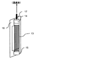
図3に示す分離膜エレメントについて説明する。図3は、本発明で用いられる分離膜エレメントを例示説明するための概略斜視図である。本発明の化学品の製造方法で用いられる連続発酵装置では、好ましくは、国際公開第2002/064240号パンフレットに開示されている分離膜および分離膜エレメントを用いることができる。分離膜エレメントは、図3に示されるように、剛性を有する支持板13の両面に、流路材14と前記の分離膜15(多孔性膜)をこの順序で配し構成されている。支持板13は、両面に凹部16を有している。分離膜15は、発酵培養液を濾過する。流路材14は、分離膜15で濾過された濾液を効率よく支持板13に流すためのものである。支持板13に流れた濾液は、支持板13の凹部16を通り、集水パイプ17を介して連続発酵装置外部に取り出される。濾液を取り出すための動力として、水頭差圧、ポンプ、液体や気体等による吸引濾過、あるいは装置系内を加圧するなどの方法を用いることができる。
The separation membrane element shown in FIG. 3 will be described. FIG. 3 is a schematic perspective view for illustrating the separation membrane element used in the present invention. In the continuous fermentation apparatus used in the method for producing a chemical product of the present invention, preferably, a separation membrane and a separation membrane element disclosed in WO2002 / 064240 can be used. As shown in FIG. 3, the separation membrane element is configured by arranging a
図4に示す分離膜エレメントについて説明する。図4は、本発明で用いられる別の分離膜エレメントを例示説明するための概略斜視図である。分離膜エレメントは、図4に示すように、中空糸膜(多孔性膜)で構成された分離膜束18と上部樹脂封止層19と下部樹脂封止層20によって主に構成される。分離膜束18は、上部樹脂封止層19および下部樹脂封止層20よって束状に接着・固定化されている。下部樹脂封止層20による接着・固定化は、分離膜束18の中空糸膜(多孔性膜)の中空部を封止しており、発酵培養液の漏出を防ぐ構造になっている。一方、上部樹脂封止層19は、分離膜束18の中空糸膜(多孔性膜)の内孔を封止しておらず、集水パイプ22に濾液が流れる構造となっている。この分離膜エレメントは、支持フレーム21を介して連続発酵装置内に設置することが可能である。分離膜束18によって濾過された濾液は、中空糸膜の中空部を通り、集水パイプ22を介して連続発酵装置外部に取り出される。濾液を取り出すための動力として、水頭差圧、ポンプ、液体や気体等による吸引濾過、あるいは装置系内を加圧するなどの方法を用いることができる。
The separation membrane element shown in FIG. 4 will be described. FIG. 4 is a schematic perspective view for illustrating another separation membrane element used in the present invention. As shown in FIG. 4, the separation membrane element is mainly composed of a separation membrane bundle 18 composed of a hollow fiber membrane (porous membrane), an upper resin sealing layer 19, and a lower
本発明の化学品の製造方法で用いられる連続発酵装置の分離膜エレメントを構成する部材は、高圧蒸気滅菌操作に耐性の部材であることが好ましい。連続発酵装置内が滅菌可能であれば、連続発酵時に好ましくない微生物による汚染の危険を回避することができ、より安定した連続発酵が可能となる。分離膜エレメントを構成する部材は、高圧蒸気滅菌操作の条件である、121℃で15分間に耐性であることが好ましい。分離膜エレメント部材は、例えば、ステンレスやアルミニウムなどの金属、ポリアミド系樹脂、フッ素系樹脂、ポリカーボネート系樹脂、ポリアセタール系樹脂、ポリブチレンテレフタレート系樹脂、PVDF、変性ポリフェニレンエーテル系樹脂およびポリサルホン系樹脂等の樹脂を好ましく選定できる。 The member constituting the separation membrane element of the continuous fermentation apparatus used in the method for producing a chemical product of the present invention is preferably a member resistant to high-pressure steam sterilization operation. If the inside of the continuous fermentation apparatus can be sterilized, it is possible to avoid the risk of contamination by undesirable microorganisms during continuous fermentation, and more stable continuous fermentation is possible. The members constituting the separation membrane element are preferably resistant to 15 minutes at 121 ° C., which is the condition of the high-pressure steam sterilization operation. Separation membrane element members include, for example, metals such as stainless steel and aluminum, polyamide resins, fluorine resins, polycarbonate resins, polyacetal resins, polybutylene terephthalate resins, PVDF, modified polyphenylene ether resins, and polysulfone resins. A resin can be preferably selected.
本発明の化学品の製造方法で用いられる連続発酵装置では、分離膜エレメントは、図1のように発酵反応槽内に設置しても良いし、図2のように発酵反応槽外に設置しても良い。分離膜エレメントを発酵反応槽外に設置する場合には、別途、膜分離槽を設けてその内部に分離膜エレメントを設置することができ、発酵反応槽と膜分離槽の間を発酵培養液を循環させながら、分離膜エレメントにより発酵培養液を連続的に濾過することができる。 In the continuous fermentation apparatus used in the method for producing a chemical product of the present invention, the separation membrane element may be installed in the fermentation reaction tank as shown in FIG. 1 or installed outside the fermentation reaction tank as shown in FIG. May be. When the separation membrane element is installed outside the fermentation reaction tank, a separate membrane separation tank can be provided and the separation membrane element can be installed inside, and the fermentation culture solution is placed between the fermentation reaction tank and the membrane separation tank. While circulating, the fermentation broth can be continuously filtered by the separation membrane element.
本発明の化学品の製造方法で用いられる連続発酵装置では、膜分離槽は、高圧蒸気滅菌可能であることが望ましい。膜分離槽が高圧蒸気滅菌可能であると、雑菌による汚染回避が容易である。 In the continuous fermentation apparatus used in the method for producing a chemical product of the present invention, the membrane separation tank is preferably capable of high-pressure steam sterilization. If the membrane separation tank can be autoclaved, it is easy to avoid contamination with germs.
本発明に従って連続発酵を行った場合、高い体積生産速度が得られるとともに、その体積生産速度を長期間維持した極めて効率のよい連続発酵生産が可能となる。ここで、連続発酵培養における生産速度は、次の式(3)で計算される。 When continuous fermentation is performed according to the present invention, a high volumetric production rate can be obtained, and extremely efficient continuous fermentation production can be performed while maintaining the volumetric production rate for a long period of time. Here, the production rate in continuous fermentation culture is calculated by the following equation (3).
・発酵生産速度(g/L/hr)=抜き取り液中の生産物濃度(g/L)×発酵培養液抜き取り速度(L/hr)÷装置の運転液量(L)・・・・(式3)
また、バッチ培養での発酵生産速度は、原料炭素源をすべて消費した時点の生産物量(g)を、炭素源の消費に要した時間(h)とその時点の発酵培養液量(L)で除して求められる。
Fermentation production rate (g / L / hr) = Product concentration in the drawn liquid (g / L) × Fermentation culture liquid drawing speed (L / hr) ÷ Device operating liquid volume (L) 3)
In addition, the fermentation production rate in batch culture is calculated based on the amount of product (g) at the time when all the raw carbon source is consumed by the time (h) required for consumption of the carbon source and the amount of fermentation broth (L) at that time. It is obtained by dividing.
以下、本発明の連続発酵による化学品の製造方法をさらに詳細に説明するために、上記の発酵生産物として乳酸を選定し、図1ならびに図2に示す連続発酵装置を用いて連続的な乳酸の発酵生産について実施例を挙げて説明する。 Hereinafter, in order to describe the method for producing a chemical product by continuous fermentation of the present invention in more detail, lactic acid is selected as the fermentation product, and continuous lactic acid is used using the continuous fermentation apparatus shown in FIGS. 1 and 2. An example is given and demonstrated about fermentation production of this.
ここで、L−乳酸を生産させる微生物には、酵母サッカロミセス・セレビセ(Saccharomyces cerevisae)を用いた。サッカロミセス・セレビセは、本来L−乳酸発酵を持たないが、L−乳酸脱水素酵素をコードする遺伝子をサッカロミセス・セレビセに導入することによりL−乳酸発酵能力をもつサッカロミセス・セレビセ株を造成し実施した。具体的には、ヒト由来LDH遺伝子を酵母ゲノム上のPDC1プロモーターの下流に連結することにより、L−乳酸発酵能力を持つ酵母株を造成して使用した。またD−乳酸を生産させる微生物には、スポロラクトバチルス・ラエボラクティカス(Sporolactobacillus laevolacticus)を用いた。 Here, yeast Saccharomyces cerevisiae was used as a microorganism for producing L-lactic acid. Saccharomyces cerevisiae originally did not have L-lactic acid fermentation, but by introducing a gene encoding L-lactate dehydrogenase into Saccharomyces cerevisiae, a Saccharomyces cerevisiae strain having L-lactic acid fermentation ability was constructed and implemented. . Specifically, a yeast strain having L-lactic acid fermentation ability was constructed and used by linking the human-derived LDH gene downstream of the PDC1 promoter on the yeast genome. As a microorganism for producing D-lactic acid, Sporolactobacillus lavolacticus was used.
[参考例1]乳酸生産能力を持つ酵母株の作製
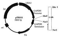
乳酸生産能力を持つ酵母株を、下記のように造成した。具体的には、ヒト由来LDH遺伝子を酵母ゲノム上のPDC1プロモーターの下流に連結することにより、L−乳酸生産能力を持つ酵母株を造成する。ポリメラーゼ・チェーン・リアクション(PCR)には、La−Taq(宝酒造社製)あるいはKOD−Plus−polymerase(東洋紡社製)を用い、付属の取扱説明に従って行った。
[Reference Example 1] Preparation of yeast strain having lactic acid production ability A yeast strain having lactic acid production ability was constructed as follows. Specifically, a yeast strain capable of producing L-lactic acid is constructed by linking a human-derived LDH gene downstream of the PDC1 promoter on the yeast genome. For polymerase chain reaction (PCR), La-Taq (Takara Shuzo Co., Ltd.) or KOD-Plus-polymerase (Toyobo Co., Ltd.) was used according to the attached instruction manual.
ヒト乳ガン株化細胞(MCF−7)を培養回収後、TRIZOL Reagent(Invitrogen)を用いてtotal RNAを抽出し、得られたtotal RNAを鋳型としてSuperScript Choice System(Invitrogen)を用いた逆転写反応によりcDNAの合成を行った。これらの操作の詳細は、それぞれ付属のプロトコールに従った。得られたcDNAを、続くPCRの増幅鋳型とした。 After culturing and recovering human breast cancer cell line (MCF-7), total RNA was extracted using TRIZOL Reagent (Invitrogen), and reverse transcription reaction using SuperScript Choice System (Invitrogen) using the obtained total RNA as a template. cDNA synthesis was performed. Details of these operations followed the attached protocol. The obtained cDNA was used as an amplification template for subsequent PCR.
上記の操作で得られたcDNAを増幅鋳型とし、配列番号1および配列番号2で表されるオリゴヌクレオチドをプライマーセットとしたKOD−Plus−polymeraseによるPCRにより、L−ldh遺伝子のクローニングを行った。各PCR増幅断片を精製し末端をT4 Polynucleotide Kinase(TAKARA社製)によりリン酸化後、pUC118ベクター(制限酵素HincIIで切断し、切断面を脱リン酸化処理したもの)にライゲーションした。ライゲーションは、DNA Ligation Kit Ver.2(TAKARA社製)を用いて行った。 The L-ldh gene was cloned by PCR using KOD-Plus-polymerase using the cDNA obtained by the above operation as an amplification template and the oligonucleotides represented by SEQ ID NO: 1 and SEQ ID NO: 2 as a primer set. Each PCR amplified fragment was purified, and the end was phosphorylated with T4 Polynucleotide Kinase (manufactured by TAKARA), and then ligated to pUC118 vector (which was cleaved with restriction enzyme HincII and the cleaved surface was dephosphorylated). Ligation was performed using DNA Ligation Kit Ver. 2 (manufactured by TAKARA).
ライゲーションプラスミド産物で大腸菌DH5αを形質転換し、プラスミドDNAを回収することにより、各種L−ldh遺伝子(配列番号3)がサブクローニングされたプラスミドを得た。得られたL−ldh遺伝子が挿入されたpUC118プラスミドを制限酵素XhoIおよびNotIで消化し、得られた各DNA断片を酵母発現用ベクターpTRS11(図5)のXhoI/NotI切断部位に挿入した。このようにして、ヒト由来L−ldh遺伝子発現プラスミドpL−ldh5(L−ldh遺伝子)を得た。ヒト由来のL−ldh遺伝子発現ベクターである上記pL−ldh5は、プラスミド単独で独立行政法人産業技術総合研究所 特許生物寄託センター(茨城県つくば市東1−1−1中央第6)にFERMAP−20421として寄託した(寄託日:平成17年2月21日)。 Escherichia coli DH5α was transformed with the ligation plasmid product, and the plasmid DNA was recovered to obtain a plasmid in which various L-ldh genes (SEQ ID NO: 3) were subcloned. The obtained pUC118 plasmid into which the L-ldh gene was inserted was digested with restriction enzymes XhoI and NotI, and the resulting DNA fragments were inserted into the XhoI / NotI cleavage sites of the yeast expression vector pTRS11 (FIG. 5). In this manner, a human-derived L-ldh gene expression plasmid pL-ldh5 (L-ldh gene) was obtained. The above-mentioned pL-ldh5, which is a human-derived L-ldh gene expression vector, is FERMAP-20421 at the National Institute of Advanced Industrial Science and Technology Patent Biological Depositary Center (1-1-1 Higashi 1-1-1, Tsukuba, Ibaraki Prefecture) as a plasmid alone. (Deposit date: February 21, 2005).
ヒト由来LDH遺伝子を含むプラスミドpL−ldh5を増幅鋳型とし、配列番号4および配列番号5で表されるオリゴヌクレオチドをプライマーセットとしたPCRにより、1.3kbのヒト由来LDH遺伝子およびサッカロミセス・セレビセ由来のTDH3遺伝子のターミネーター配列含むDNA断片を増幅した。また、プラスミドpRS424を増幅鋳型として、配列番号6および配列番号7で表されるオリゴヌクレオチドをプライマーセットとしたPCRにより、1.2kbのサッカロミセス・セレビセ由来のTRP1遺伝子を含むDNA断片を増幅した。それぞれのDNA断片を、1.5%アガロースゲル電気泳動により分離し、常法に従い精製した。 By PCR using the plasmid pL-ldh5 containing the human-derived LDH gene as an amplification template and the oligonucleotides represented by SEQ ID NO: 4 and SEQ ID NO: 5 as a primer set, a 1.3-kb human-derived LDH gene and Saccharomyces cerevisiae derived A DNA fragment containing the terminator sequence of the TDH3 gene was amplified. In addition, a DNA fragment containing the TRP1 gene derived from Saccharomyces cerevisiae of 1.2 kb was amplified by PCR using the plasmid pRS424 as an amplification template and the oligonucleotides represented by SEQ ID NO: 6 and SEQ ID NO: 7 as a primer set. Each DNA fragment was separated by 1.5% agarose gel electrophoresis and purified according to a conventional method.
ここで得られた1.3kb断片と1.2kb断片を混合したものを増幅鋳型とし、配列番号4および配列番号7で表されるオリゴヌクレオチドをプライマーセットとしたPCR法によって得られた産物を1.5%アガロースゲル電気泳動して、ヒト由来LDH遺伝子およびTRP1遺伝子が連結された2.5kbのDNA断片を、常法に従い調整した。この2.5kbのDNA断片で、出芽酵母NBRC10505株を常法に従いトリプトファン非要求性に形質転換した。 A product obtained by PCR using a mixture of the 1.3 kb fragment and the 1.2 kb fragment obtained here as an amplification template and the oligonucleotides represented by SEQ ID NO: 4 and SEQ ID NO: 7 as a primer set was obtained as 1 A 2.5 kb DNA fragment to which the human-derived LDH gene and TRP1 gene were linked was prepared according to a conventional method by electrophoresis on 5% agarose gel. With this 2.5 kb DNA fragment, the budding yeast strain NBRC10505 was transformed to tryptophan non-requirement according to a conventional method.
得られた形質転換細胞が、ヒト由来LDH遺伝子を酵母ゲノム上のPDC1プロモーターの下流に連結されている細胞であることの確認は、下記のようにして行った。まず、形質転換細胞のゲノムDNAを常法に従って調製し、これを増幅鋳型とした配列番号8および配列番号9で表されるオリゴヌクレオチドをプライマーセットとしたPCRにより、0.7kbの増幅DNA断片が得られることにより確認した。 Confirmation that the obtained transformed cells were cells in which the human-derived LDH gene was linked downstream of the PDC1 promoter on the yeast genome was performed as follows. First, genomic DNA of a transformed cell was prepared according to a conventional method, and a 0.7 kb amplified DNA fragment was obtained by PCR using the oligonucleotides represented by SEQ ID NO: 8 and SEQ ID NO: 9 as a primer set. This was confirmed by obtaining.
また、形質転換細胞が乳酸生産能力を持つかどうかは、表1に示すSC培地(METHODS IN YEAST GENETICS 2000 EDITION、 CSHL PRESS)で形質転換細胞を培養した培養上澄に乳酸が含まれていることを、下記に示す条件でHPLC法により乳酸量を測定することにより確認した。
・カラム:Shim−Pack SPR−H(島津社製)
・移動相:5mM p−トルエンスルホン酸(流速0.8mL/min)
・反応液:5mM p−トルエンスルホン酸、20mM ビストリス、0.1mM EDTA・2Na(流速0.8mL/min)
・検出方法:電気伝導度
・温度:45℃。
Whether or not the transformed cells have lactic acid production ability is determined by the fact that lactic acid is contained in the culture supernatant obtained by culturing the transformed cells in the SC medium (METHODS IN YAST GENETIC 2000 EDITION, CSHL PRESS) shown in Table 1. Was confirmed by measuring the amount of lactic acid by the HPLC method under the conditions shown below.
Column: Shim-Pack SPR-H (manufactured by Shimadzu Corporation)
-Mobile phase: 5 mM p-toluenesulfonic acid (flow rate 0.8 mL / min)
Reaction solution: 5 mM p-toluenesulfonic acid, 20 mM Bistris, 0.1 mM EDTA · 2Na (flow rate 0.8 mL / min)
-Detection method: electrical conductivity-Temperature: 45 ° C.
また、L−乳酸の光学純度測定は、下記の条件でHPLC法により測定した。
・カラム:TSK−gel Enantio L1(東ソー社製)
・移動相 :1mM 硫酸銅水溶液
・流速:1.0ml/min
・検出方法 :UV254nm
・温度 :30℃。
The optical purity of L-lactic acid was measured by the HPLC method under the following conditions.
Column: TSK-gel Enantio L1 (manufactured by Tosoh Corporation)
-Mobile phase: 1 mM aqueous copper sulfate-Flow rate: 1.0 ml / min
・ Detection method: UV254nm
-Temperature: 30 degreeC.
また、L−乳酸の光学純度は、次式で計算される。
・光学純度(%)=100×(L−D)/(L+D)
ここで、LはL−乳酸の濃度であり、DはD−乳酸の濃度を表す。
Moreover, the optical purity of L-lactic acid is calculated by the following formula.
Optical purity (%) = 100 × (LD) / (L + D)
Here, L represents the concentration of L-lactic acid, and D represents the concentration of D-lactic acid.
HPLC分析の結果、4g/LのL−乳酸が検出され、D−乳酸は検出限界以下であった。以上の検討により、この形質転換体がL−乳酸生産能力を持つことが確認された。得られた形質転換細胞を、酵母SW−1株として、後の実施例で用いた。 As a result of HPLC analysis, 4 g / L of L-lactic acid was detected, and D-lactic acid was below the detection limit. From the above examination, it was confirmed that this transformant has L-lactic acid production ability. The obtained transformed cell was used in a later example as a yeast SW-1 strain.
[参考例2]多孔性膜の作製(その1)
樹脂としてポリフッ化ビニリデン(PVDF)樹脂を、また溶媒としてN,N−ジメチルアセトアミド(DMAc)をそれぞれ用い、これらを90℃の温度下に十分に攪拌し、次の組成を有する原液を得た。
[Reference Example 2] Production of porous membrane (Part 1)
Polyvinylidene fluoride (PVDF) resin was used as the resin and N, N-dimethylacetamide (DMAc) was used as the solvent, and these were sufficiently stirred at a temperature of 90 ° C. to obtain a stock solution having the following composition.
[原液]
・PVDF:13.0重量%
・DMAc:87.0重量%。
[Undiluted solution]
・ PVDF: 13.0% by weight
DMAc: 87.0% by weight.
次に、上記原液を25℃の温度に冷却した後、あらかじめガラス板上に貼り付けて置いた、密度が0.48g/cm3で、厚みが220μmのポリエステル繊維製不織布(多孔質基材)に塗布し、直ちに次の組成を有する25℃の温度の凝固浴中に5分間浸漬して、多孔質基材に多孔質樹脂層が形成された多孔性膜を得た。 Next, after the stock solution is cooled to a temperature of 25 ° C., a non-woven fabric made of polyester fiber (porous substrate) having a density of 0.48 g / cm 3 and a thickness of 220 μm, which is previously pasted on a glass plate. And immediately immersed in a coagulation bath at 25 ° C. having the following composition for 5 minutes to obtain a porous film having a porous resin layer formed on a porous substrate.
[凝固浴]
・水 :30.0重量%
・DMAc:70.0重量%。
[Coagulation bath]
-Water: 30.0% by weight
DMAc: 70.0% by weight.
この多孔性膜をガラス板から剥がした後、80℃の温度の熱水に3回浸漬してDMAcを洗い出し、分離膜を得た。多孔質樹脂層表面の9.2μm×10.4μmの範囲内を、倍率10,000倍で走査型電子顕微鏡観察を行ったところ、観察できる細孔すべての直径の平均は0.1μmであった。次に、上記分離膜について純水透水透過係数を評価したところ、50×10-9m3/m2/s/Paであった。純水透水量の測定は、逆浸透膜による25℃の温度の精製水を用い、ヘッド高さ1mで行った。また、平均細孔径の標準偏差は0.035μmで、膜表面粗さは0.06μmであった。 After peeling this porous membrane from the glass plate, it was immersed in hot water at a temperature of 80 ° C. three times to wash out DMAc to obtain a separation membrane. When the surface of the porous resin layer was observed with a scanning electron microscope at a magnification of 10,000 within the range of 9.2 μm × 10.4 μm, the average diameter of all observable pores was 0.1 μm. . Next, when the pure water permeability coefficient was evaluated about the said separation membrane, it was 50 * 10 < -9 > m < 3 > / m < 2 > / s / Pa. The pure water permeation amount was measured using purified water at a temperature of 25 ° C. by a reverse osmosis membrane at a head height of 1 m. The standard deviation of the average pore diameter was 0.035 μm, and the membrane surface roughness was 0.06 μm.
[参考例3]多孔性膜の作製(その2)
重量平均分子量41.7万のフッ化ビニリデンホモポリマーとγ−ブチロラクトンとを、それぞれ38重量%と62重量%の割合で170℃の温度で溶解し原液を作製した。この原液をγ−ブチロラクトンを中空部形成液体として随拌させながら口金から吐出し、温度20℃のγ−ブチロラクトン80重量%水溶液からなる冷却浴中で固化して中空糸膜を作製した。
[Reference Example 3] Production of porous membrane (part 2)
A vinylidene fluoride homopolymer having a weight average molecular weight of 41,000 and γ-butyrolactone were dissolved at a temperature of 170 ° C. at a ratio of 38% by weight and 62% by weight, respectively, to prepare a stock solution. This stock solution was discharged from the base while stirring γ-butyrolactone as a hollow portion forming liquid, and solidified in a cooling bath composed of an 80% by weight aqueous solution of γ-butyrolactone at a temperature of 20 ° C. to produce a hollow fiber membrane.
次いで、重量平均分子量28.4万のフッ化ビニリデンホモポリマーを14重量%、セルロースアセテートプロピオネート(イーストマンケミカル社、CAP482−0.5)を1重量%、N-メチル-2-ピロリドンを77重量%、ポリオキシエチレンヤシ油脂肪酸ソルビタン(三洋化成株式会社、商品名“イオネットT−20C”(登録商標))を5重量%、および水を3重量%の割合で95℃の温度で混合溶解して原液を調整した。この原液を、上記で得られた中空糸膜の表面に均一に塗布し、すぐに水浴中で凝固させた本発明で用いる中空糸多孔性膜を製作した。得られた中空糸多孔性膜の被処理水側表面の平均細孔径は、0.05μmであった。次に、上記の分離膜である中空糸多孔性膜について純水透水量を評価したところ、5.5×10⁻⁹m3/m2・s・Paであった。透水量の測定は、逆浸透膜による25℃の温度の精製水を用い、ヘッド高さ1mで行った。また、平均細孔径の標準偏差 は0.006μmであった。 Next, 14% by weight of vinylidene fluoride homopolymer having a weight average molecular weight of 284,000, 1% by weight of cellulose acetate propionate (Eastman Chemical Co., CAP482-0.5), and N-methyl-2-pyrrolidone 77% by weight, polyoxyethylene coconut oil fatty acid sorbitan (Sanyo Kasei Co., Ltd., trade name “IONET T-20C” (registered trademark)) 5% by weight, and water 3% by weight at a temperature of 95 ° C. The stock solution was prepared by dissolving. This undiluted solution was uniformly applied to the surface of the hollow fiber membrane obtained above, and a hollow fiber porous membrane used in the present invention was immediately solidified in a water bath. The average pore diameter of the treated water side surface of the obtained hollow fiber porous membrane was 0.05 μm. Next, the pure water permeation rate of the hollow fiber porous membrane as the separation membrane was evaluated and found to be 5.5 × 10 −9 m 3 / m 2 · s · Pa. The amount of water permeation was measured using purified water at a temperature of 25 ° C. by a reverse osmosis membrane at a head height of 1 m. The standard deviation of the average pore diameter was 0.006 μm.
[実施例1]連続発酵によるL−乳酸の製造(その1)
図1に示す連続発酵装置を稼働させることにより、L−乳酸連続発酵系が得られるかどうかを調べるため、表2に示す組成の乳酸発酵培地を用い、この装置の連続発酵試験を行った。該乳酸発酵培地は、121℃の温度で15分間、高圧蒸気滅菌して用いた。分離膜には、前記の参考例2で作製した多孔性膜を用いた。実施例1における運転条件は、特に断らない限り下記のとおりである。
[Example 1] Production of L-lactic acid by continuous fermentation (part 1)
In order to examine whether or not an L-lactic acid continuous fermentation system can be obtained by operating the continuous fermentation apparatus shown in FIG. 1, a continuous fermentation test of this apparatus was performed using a lactic acid fermentation medium having the composition shown in Table 2. The lactic acid fermentation medium was used after being autoclaved at 121 ° C. for 15 minutes. As the separation membrane, the porous membrane prepared in Reference Example 2 was used. The operating conditions in Example 1 are as follows unless otherwise specified.
[運転条件]
・発酵反応槽容量:1.5(L)
・膜分離槽容量:0.5(L)
・使用分離膜:PVDF濾過膜
・膜分離エレメント有効濾過面積:120平方cm
・温度調整:30(℃)
・発酵反応槽通気量:0.02(L/min)
・膜分離槽通気量:0.3(L/min)
・発酵反応槽攪拌速度:800(rpm)
・pH調整:1N NaOHによりpH5に調整
・発酵培養液循環装置による循環液量:0.1(L/min)
・膜透過水量制御:膜分離槽水頭差により流量を制御(膜間差圧として20kPa以下に制御した。)
・間欠的な濾過処理:濾過処理(9分間)−非濾過処理(1分間)の周期運転。
[Operating conditions]
・ Fermentation reactor capacity: 1.5 (L)
・ Membrane separation tank capacity: 0.5 (L)
-Separation membrane used: PVDF filtration membrane-Membrane separation element Effective filtration area: 120 square cm
・ Temperature adjustment: 30 (℃)
-Aeration volume of fermentation reaction tank: 0.02 (L / min)
-Aeration rate of membrane separation tank: 0.3 (L / min)
・ Fermentation reactor stirring speed: 800 (rpm)
-PH adjustment: adjusted to
-Membrane permeate flow rate control: The flow rate was controlled by the difference in the water head of the membrane separation tank (the transmembrane pressure difference was controlled to 20 kPa or less.)
-Intermittent filtration treatment: Periodic operation of filtration treatment (9 minutes)-non-filtration treatment (1 minute).
微生物もしくは培養細胞として前記の参考例1で造成した酵母SW−1株を用い、培地として表2に示す組成の乳酸発酵培地を用いた。生産物であるL−乳酸の濃度の評価には、前記の参考例1に示したHPLCを用い、グルコース濃度の測定には“グルコーステストワコーC”(登録商標)(和光純薬社製)を用いた。 The yeast SW-1 strain prepared in Reference Example 1 was used as the microorganism or cultured cell, and the lactic acid fermentation medium having the composition shown in Table 2 was used as the medium. For the evaluation of the concentration of L-lactic acid as a product, the HPLC shown in Reference Example 1 was used, and for measuring the glucose concentration, “Glucose Test Wako C” (registered trademark) (manufactured by Wako Pure Chemical Industries, Ltd.) was used. Using.
まず、試験管中で5mlの乳酸発酵培地を用いSW−1株を一晩振とう培養した(前々々培養)。得られた培養液を新鮮な乳酸発酵培地100mlに植菌し、500ml容坂口フラスコ中で24時間、30℃の温度で振とう培養した(前々培養)。前々培養液を、図1に示した連続発酵装置の1.5Lの乳酸発酵培地に植菌し、発酵反応槽1を付属の攪拌機5によって800rpmで攪拌し、発酵反応槽1の通気量の調整、温度調整およびpH調整を行った。発酵培養液循環ポンプ11を稼働させることなく、24時間培養を行った(前培養)。前培養完了後、直ちに、発酵培養液循環ポンプ11を稼働させた。前培養時の運転条件に加え、膜分離槽2を通気し、乳酸発酵培地の連続供給を行い、連続発酵装置の発酵培養液量を2Lとなるように膜透過水量の制御を行いながら間欠的に発酵培養液を濾過・分離し連続培養することにより、連続発酵によるL−乳酸の製造を行った。連続発酵試験を行うときの膜透過水量の制御は、水頭差制御装置3により、膜間差圧が0.1〜20kPa以内となるように適宜水頭差を変化させることによって行い、かつ、間欠的な濾過処理を、9分間の濾過処理操作と1分間の非濾過処理操作を繰り返すことによって行った。適宜、濾液中の生産されたL−乳酸濃度および残存グルコース濃度を測定した。連続発酵開始から550時間の間、膜間差圧が0.1〜20kPa以内で安定してL−乳酸を発酵生産することができた。表3に、培養発酵の条件と結果を示す。
First, the SW-1 strain was cultured with shaking overnight in a test tube using 5 ml of lactic acid fermentation medium (pre-culture). The obtained culture solution was inoculated into 100 ml of a fresh lactic acid fermentation medium, and cultured with shaking at a temperature of 30 ° C. for 24 hours in a 500 ml Sakaguchi flask (pre-culture). The culture solution is inoculated in a 1.5 L lactic acid fermentation medium of the continuous fermentation apparatus shown in FIG. 1, the
[比較例1]連続発酵によるL−乳酸の製造(その1)
実施例1の比較対照として、濾過処理を連続的に行いL−乳酸の連続発酵を行った結果、連続発酵開始後300時間で膜間差圧が20kPaを超えた。表3に、培養発酵の条件と結果を示す。
[Comparative Example 1] Production of L-lactic acid by continuous fermentation (part 1)
As a comparative control of Example 1, continuous filtration treatment and continuous fermentation of L-lactic acid resulted in a transmembrane differential pressure exceeding 20 kPa 300 hours after the start of continuous fermentation. Table 3 shows the conditions and results of the culture fermentation.
図6は、実施例1と比較例1の発酵時間と膜間差圧を比較したグラフである。この図から、本発明の化学品の製造方法により、長期間安定して化学品を製造できることが明らかになった。 FIG. 6 is a graph comparing the fermentation time and transmembrane pressure difference between Example 1 and Comparative Example 1. From this figure, it became clear that the chemical product can be stably produced for a long period of time by the chemical product production method of the present invention.
[実施例2]連続発酵によるL−乳酸の製造(その2)
分離膜として参考例3で作成した多孔性膜を用い、その他は実施例1と同様にL−乳酸の連続発酵を行った。その結果、連続発酵開始から500時間の間、膜間差圧が0.1〜20kPa以内で安定してL−乳酸を発酵生産することができた。表3に、培養発酵の条件と結果を示す。
[Example 2] Production of L-lactic acid by continuous fermentation (part 2)
The porous membrane prepared in Reference Example 3 was used as the separation membrane, and L-lactic acid was continuously fermented in the same manner as in Example 1. As a result, L-lactic acid was able to be fermented and produced stably for 500 hours from the start of continuous fermentation within a transmembrane pressure difference of 0.1 to 20 kPa. Table 3 shows the conditions and results of the culture fermentation.
[比較例2]連続発酵によるL−乳酸の製造(その2)
実施例2の比較対照として、濾過処理を連続的に行いL−乳酸の連続発酵を行った結果、連続発酵開始後300時間で膜間差圧が20kPaを超えた。表3に、培養発酵の条件と結果を示す。
[Comparative Example 2] Production of L-lactic acid by continuous fermentation (part 2)
As a comparative control of Example 2, as a result of continuous filtration and continuous fermentation of L-lactic acid, the transmembrane pressure difference exceeded 20 kPa in 300 hours after the start of continuous fermentation. Table 3 shows the conditions and results of the culture fermentation.
図7は、実施例2と比較例2の発酵時間と膜間差圧を比較したグラフである。この図から、本発明の化学品の製造方法により、長期間安定して化学品を製造できることが明らかになった
[実施例3]連続発酵によるL−乳酸の製造(その3)
図2に示す連続発酵装置を稼働させることにより、L−乳酸連続発酵系が得られるかどうかを調べるため、表2に示す組成の乳酸発酵培地を用い、この装置の連続発酵試験を行った。該乳酸発酵培地は、121℃の温度で15分間、高圧蒸気滅菌して用いた。分離膜には、前記の参考例1で作製した多孔性膜を用いた。実施例1における運転条件は、特に断らない限り下記のとおりである。
FIG. 7 is a graph comparing the fermentation time and transmembrane pressure in Example 2 and Comparative Example 2. From this figure, it was clarified that the chemical product production method of the present invention can stably produce a chemical product for a long period of time. [Example 3] Production of L-lactic acid by continuous fermentation (part 3)
In order to investigate whether or not an L-lactic acid continuous fermentation system can be obtained by operating the continuous fermentation apparatus shown in FIG. 2, a continuous fermentation test of this apparatus was performed using a lactic acid fermentation medium having the composition shown in Table 2. The lactic acid fermentation medium was used after being autoclaved at 121 ° C. for 15 minutes. As the separation membrane, the porous membrane prepared in Reference Example 1 was used. The operating conditions in Example 1 are as follows unless otherwise specified.
[運転条件]
・発酵反応槽容量:1.5(L)
・使用分離膜:PVDF濾過膜
・膜分離エレメント有効濾過面積:120平方cm
・温度調整:30(℃)
・発酵反応槽通気量:0.02(L/min)
・発酵反応槽攪拌速度:800(rpm)
・pH調整:1N NaOHによりpH5に調整
・膜透過水量制御:膜分離槽水頭差により流量を制御(膜間差圧として20kPa以下に制御した。)
・間欠的な濾過処理:濾過処理(9分間)−非濾過処理(1分間)の周期運転。
[Operating conditions]
・ Fermentation reactor capacity: 1.5 (L)
-Separation membrane used: PVDF filtration membrane-Membrane separation element Effective filtration area: 120 square cm
・ Temperature adjustment: 30 (℃)
-Aeration volume of fermentation reaction tank: 0.02 (L / min)
・ Fermentation reactor stirring speed: 800 (rpm)
-PH adjustment: pH adjusted to 5 with 1N NaOH-Membrane permeate flow rate control: Flow rate is controlled by the difference in the water head of the membrane separation tank (the transmembrane pressure difference is controlled to 20 kPa or less.)
-Intermittent filtration treatment: Periodic operation of filtration treatment (9 minutes)-non-filtration treatment (1 minute).
微生物として前記の参考例1で造成した酵母SW−1株を用い、培地として表1に示す組成の乳酸発酵培地を用いた。生産物であるL−乳酸の濃度の評価には、前記の参考例1に示したHPLCを用い、グルコース濃度の測定には“グルコーステストワコーC”(登録商標)(和光純薬社製)を用いた。 The yeast SW-1 strain constructed in Reference Example 1 was used as the microorganism, and a lactic acid fermentation medium having the composition shown in Table 1 was used as the medium. For the evaluation of the concentration of L-lactic acid as a product, the HPLC shown in Reference Example 1 was used, and for measuring the glucose concentration, “Glucose Test Wako C” (registered trademark) (manufactured by Wako Pure Chemical Industries, Ltd.) was used. Using.
まず、試験管中で5mlの乳酸発酵培地を用いSW−1株を一晩振とう培養した(前々々培養)。得られた培養液を新鮮な乳酸発酵培地100mlに植菌し、500ml容坂口フラスコ中で24時間、30℃の温度で振とう培養した(前々培養)。前々培養液を、図1に示した膜分離型の連続発酵装置の1.5Lの乳酸発酵培地に植菌し、発酵反応槽1を付属の攪拌機5によって500rpmで攪拌し、発酵反応槽1の通気量の調整、温度調整およびpH調整を行った。発酵培養液循環ポンプ11を稼働させることなく、24時間培養を行った(前培養)。前培養完了後、直ちに、乳酸発酵培地の連続供給を行い、連続発酵装置の発酵培養液量を1.5Lとなるよう膜透過水量の制御を行いながら間欠的に発酵培養液を濾過・分離し連続培養することで、連続発酵によるL−乳酸の製造を行った。連続発酵試験を行うときの膜透過水量の制御は、水頭差制御装置3により、膜間差圧が0.1〜20kPa以内となるように適宜水頭差を変化させることによって行い、かつ、間欠的な濾過処理を、9分間の濾過処理操作と1分間の非濾過処理操作を繰り返すことによって行った。適宜、濾液中の生産されたL−乳酸濃度および残存グルコース濃度を測定した。連続発酵開始から480時間の間、膜間差圧が0.1〜20kPa以内で安定してL−乳酸を発酵生産することができた。表3に、培養発酵の条件と結果を示す。
First, the SW-1 strain was cultured with shaking overnight in a test tube using 5 ml of lactic acid fermentation medium (pre-culture). The obtained culture solution was inoculated into 100 ml of a fresh lactic acid fermentation medium, and cultured with shaking at a temperature of 30 ° C. for 24 hours in a 500 ml Sakaguchi flask (pre-culture). The culture solution is inoculated in a 1.5 L lactic acid fermentation medium of the membrane-separated continuous fermentation apparatus shown in FIG. 1, and the
[比較例3]連続発酵によるL−乳酸の製造(その3)
実施例3の比較対照として、濾過処理を連続的に行いL−乳酸の連続発酵を行った結果、連続発酵開始後250時間で膜間差圧が20kPaを超えた。表3に、培養発酵の条件と結果を示す。
[Comparative Example 3] Production of L-lactic acid by continuous fermentation (part 3)
As a comparative control of Example 3, as a result of continuous filtration treatment and continuous fermentation of L-lactic acid, the transmembrane pressure difference exceeded 20 kPa in 250 hours after the start of continuous fermentation. Table 3 shows the conditions and results of the culture fermentation.
図8は、実施例3と比較例3の発酵時間と膜間差圧を比較したグラフである。この図から、本発明の化学品の製造方法により、長期間安定して化学品を製造できることが明らかになった
[実施例4]連続発酵によるL−乳酸の製造(その4)
分離膜として参考例3で作成した多孔性膜を用い、その他は実施例1と同様にL−乳酸の連続発酵を行った。その結果、連続発酵開始から450時間の間、膜間差圧が0.1〜20kPa以内で安定してL−乳酸を発酵生産することができた。表3に、培養発酵の条件と結果を示す。
FIG. 8 is a graph comparing the fermentation time and transmembrane pressure in Example 3 and Comparative Example 3. From this figure, it was clarified that the chemical product production method of the present invention can stably produce a chemical product for a long period of time. [Example 4] Production of L-lactic acid by continuous fermentation (part 4)
The porous membrane prepared in Reference Example 3 was used as the separation membrane, and L-lactic acid was continuously fermented in the same manner as in Example 1. As a result, L-lactic acid could be fermented and produced stably for 450 hours from the start of continuous fermentation within a transmembrane pressure difference of 0.1 to 20 kPa. Table 3 shows the conditions and results of the culture fermentation.
[比較例4]連続発酵によるL−乳酸の製造(その4)
実施例4の比較対照として、濾過処理を連続的に行いL−乳酸の連続発酵を行った結果、連続発酵開始後240時間で膜間差圧が20kPaを超えた。表3に、培養発酵の条件と結果を示す。
[Comparative Example 4] Production of L-lactic acid by continuous fermentation (part 4)
As a comparative control of Example 4, as a result of continuous filtration and continuous fermentation of L-lactic acid, the transmembrane pressure difference exceeded 20 kPa in 240 hours after the start of continuous fermentation. Table 3 shows the conditions and results of the culture fermentation.
図9は、実施例4と比較例4の発酵時間と膜間差圧を比較したグラフである。この図から、本発明の化学品の製造方法により、長期間安定して化学品を製造できることが明らかになった。 FIG. 9 is a graph comparing the fermentation time and transmembrane pressure in Example 4 and Comparative Example 4. From this figure, it became clear that the chemical product can be stably produced for a long period of time by the chemical product production method of the present invention.
[実施例5]連続発酵によるD−乳酸の製造(その1)
微生物としてスポロラクトバチルス・ラエボラクティカス ATCC23492株を用い、培地にグルコース80g/Lと酵母エキス3g/Lを含む乳酸発酵培地を用いて、図1の連続発酵装置でD−乳酸連続発酵を行った。該乳酸発酵培地は、121℃の温度で15分間、高圧蒸気滅菌して用いた。分離膜には、前記の参考例2で作製した多孔性膜を用いた。運転条件は下記のとおりである。
[Example 5] Production of D-lactic acid by continuous fermentation (part 1)
1 using a lactic acid fermentation medium containing 80 g / L of glucose and 3 g / L of yeast extract in the medium using Sporolactobacillus laevolacticus ATCC23492 as a microorganism went. The lactic acid fermentation medium was used after being autoclaved at 121 ° C. for 15 minutes. As the separation membrane, the porous membrane prepared in Reference Example 2 was used. The operating conditions are as follows.
[運転条件]
・発酵反応槽容量:1.5(L)
・使用分離膜:PVDF濾過膜
・分離膜エレメント有効濾過面積:120平方cm
・温度調整:37(℃)
・発酵反応槽通気量:窒素ガス0.2(L/min)
・発酵反応槽攪拌速度:800(rpm)
・pH調整:8N Ca(OH)2によりpH6.0に調整
・膜透過水量制御:膜分離槽水頭差により流量を制御(膜間差圧として20kPa以下に制御した。)
・間欠的な濾過処理:濾過処理(9分間)−非濾過処理(1分間)の周期運転。
[Operating conditions]
・ Fermentation reactor capacity: 1.5 (L)
-Separation membrane used: PVDF filtration membrane-Separation membrane element Effective filtration area: 120 square cm
・ Temperature adjustment: 37 (℃)
-Aeration volume of fermentation reaction tank: Nitrogen gas 0.2 (L / min)
・ Fermentation reactor stirring speed: 800 (rpm)
-PH adjustment: pH 6.0 adjusted with 8N Ca (OH) 2 -Membrane permeate flow rate control: Flow rate is controlled by the membrane head difference (controlled to 20 kPa or less as a transmembrane differential pressure)
-Intermittent filtration treatment: Periodic operation of filtration treatment (9 minutes)-non-filtration treatment (1 minute).
生産物であるD−乳酸の濃度の評価には、前記の参考例1に示したHPLCを用いた。まず、試験管中で10mlの乳酸発酵培地を用い、ATCC 23492株を嫌気条件下で一晩培養した(前々々培養)。得られた培養液を新鮮な乳酸発酵培地100mlに植菌し、嫌気条件下、500ml容坂口フラスコ中で24時間、37℃の温度で培養した(前々培養)。前々培養液を、図1に示した連続発酵装置の発酵反応槽中1の1.5Lの乳酸発酵培地に植菌し、攪拌、通気量の調整、温度調整およびpH調整を行った(前培養)。前培養開始24時間後に、乳酸発酵培地の連続供給を行い、連続発酵装置の発酵培養液量を1.5Lとなるよう膜透過水量の制御を行いながら間欠的に発酵培養液を濾過・分離し連続培養することで、連続発酵によるD−乳酸の製造を行った。連続発酵試験を行うときの膜透過水量の制御は、水頭差制御装置3により、膜間差圧が0.1〜20kPa以内となるように適宜水頭差を変化させることによって行い、かつ、間欠的な濾過処理を、9分間の濾過処理操作と1分間の非濾過処理操作を繰り返すことによって行った。適宜、濾液中の生産されたD−乳酸濃度および残存グルコース濃度を測定した。連続発酵開始から400時間の間、膜間差圧が0.1〜20kPa以内で安定してD−乳酸を発酵生産することができた。表4に、培養発酵の条件と結果を示す。 The HPLC shown in Reference Example 1 was used to evaluate the concentration of the product D-lactic acid. First, ATCC 23492 strain was cultured overnight under anaerobic conditions using 10 ml of lactic acid fermentation medium in a test tube (pre-culture). The obtained culture broth was inoculated into 100 ml of a fresh lactic acid fermentation medium and cultured at 37 ° C. for 24 hours in a 500 ml Sakaguchi flask under anaerobic conditions (pre-culture). The culture solution was inoculated into 1.5 L of lactic acid fermentation medium in 1 in the fermentation reaction tank of the continuous fermentation apparatus shown in FIG. 1, and the stirring, aeration adjustment, temperature adjustment, and pH adjustment were performed (previous) culture). 24 hours after the start of the pre-culture, the lactic acid fermentation medium is continuously supplied, and the fermentation broth is filtered and separated intermittently while controlling the amount of permeated water so that the fermentation broth of the continuous fermentation apparatus is 1.5L. By continuously culturing, D-lactic acid was produced by continuous fermentation. Control of the amount of permeated water when performing the continuous fermentation test is performed by changing the water head difference as appropriate so that the transmembrane pressure difference is within 0.1 to 20 kPa by the water head difference control device 3, and intermittently. Filtration treatment was performed by repeating the filtration treatment operation for 9 minutes and the non-filtration treatment operation for 1 minute. Where appropriate, the produced D-lactic acid concentration and residual glucose concentration in the filtrate were measured. For 400 hours from the start of continuous fermentation, the transmembrane pressure difference was within 0.1 to 20 kPa, and D-lactic acid could be produced by fermentation. Table 4 shows the conditions and results of culture fermentation.
[比較例5]連続発酵によるD−乳酸の製造(その1)
実施例5の比較対照として、濾過処理を連続的に行いL−乳酸の連続発酵を行った結果、連続発酵開始後240時間で膜間差圧が20kPaを超えた。表4に、培養発酵の条件と結果を示す。
[Comparative Example 5] Production of D-lactic acid by continuous fermentation (Part 1)
As a comparative control of Example 5, as a result of continuous filtration and continuous fermentation of L-lactic acid, the transmembrane pressure difference exceeded 20 kPa in 240 hours after the start of continuous fermentation. Table 4 shows the conditions and results of culture fermentation.
図10は、実施例5と比較例5の発酵時間と膜間差圧を比較したグラフである。この図から、本発明の化学品の製造方法により、長期間安定して化学品を製造できることが明らかになった。 FIG. 10 is a graph comparing the fermentation time and transmembrane pressure in Example 5 and Comparative Example 5. From this figure, it became clear that the chemical product can be stably produced for a long period of time by the chemical product production method of the present invention.
[実施例6]連続発酵によるD−乳酸の製造(その2)
微生物としてスポロラクトバチルス・ラエボラクティカス ATCC 23492株を用い、培地にグルコース80g/Lと酵母エキス3g/Lを含む乳酸発酵培地を用いて、図2の連続発酵装置でD−乳酸連続発酵を行った。該乳酸発酵培地は、121℃の温度で15分間、高圧蒸気滅菌して用いた。分離膜には、前記の参考例4で作製した多孔性膜を用いた。運転条件は下記のとおりである。
[Example 6] Production of D-lactic acid by continuous fermentation (part 2)
D. Lactic acid continuous fermentation using the lactic acid fermentation medium containing 80 g / L glucose and 3 g / L yeast extract in the continuous fermentation apparatus of FIG. 2 using Sporactobacillus laevolacticus ATCC 23492 as the microorganism Went. The lactic acid fermentation medium was used after being autoclaved at 121 ° C. for 15 minutes. As the separation membrane, the porous membrane prepared in Reference Example 4 was used. The operating conditions are as follows.
[運転条件]
・発酵反応槽容量:1.5(L)
・膜分離槽容量:0.5(L)
・使用分離膜:PVDF濾過膜
・分離膜エレメント有効濾過面積:120平方cm
・温度調整:37(℃)
・発酵反応槽通気量:窒素ガス0.2(L/min)
・発酵反応槽攪拌速度:800(rpm)
・pH調整:8N Ca(OH)2によりpH6.0に調整
・培養液循環速度:100ml/min
・膜透過水量制御:膜分離槽水頭差により流量を制御(膜間差圧として20kPa以下に制御した。)
・間欠的な濾過処理:濾過処理(9分間)−非濾過処理(1分間)の周期運転。
[Operating conditions]
・ Fermentation reactor capacity: 1.5 (L)
・ Membrane separation tank capacity: 0.5 (L)
-Separation membrane used: PVDF filtration membrane-Separation membrane element Effective filtration area: 120 square cm
・ Temperature adjustment: 37 (℃)
-Aeration volume of fermentation reaction tank: Nitrogen gas 0.2 (L / min)
・ Fermentation reactor stirring speed: 800 (rpm)
-PH adjustment: pH 6.0 adjusted with 8N Ca (OH) 2 -Culture medium circulation rate: 100 ml / min
-Membrane permeate flow rate control: The flow rate was controlled by the difference in the water head of the membrane separation tank (the transmembrane pressure difference was controlled to 20 kPa or less.)
-Intermittent filtration treatment: Periodic operation of filtration treatment (9 minutes)-non-filtration treatment (1 minute).
生産物であるD−乳酸の濃度の評価には、前記の参考例1に示したHPLCを用いた。分離膜の目詰まりにより濾過液が出てこなくなる時間を測定することにより、連続発酵の安定運転の比較を行った。 The HPLC shown in Reference Example 1 was used to evaluate the concentration of the product D-lactic acid. The stable operation of continuous fermentation was compared by measuring the time during which the filtrate did not come out due to clogging of the separation membrane.
まず、試験管中で10mlの乳酸発酵培地を用い、ATCC23492株を嫌気条件下で一晩培養した(前々々培養)。得られた培養液を新鮮な乳酸発酵培地100mlに植菌し、500ml容坂口フラスコで24時間、37℃で培養した(前々培養)。前々培養液を、図2に示した連続発酵装置の発酵反応槽中1の2.0LのL−乳酸発酵培地に植菌し、発酵反応槽1を付属の攪拌機5によって800rpmで攪拌し、発酵反応槽1の通気量の調整、温度調整、pH調整および培養液循環速度調整を行い、24時間培養を行った(前培養)。前培養完了後直ちに、乳酸発酵培地の連続供給を行い、連続発酵装置の発酵反応槽中1の発酵培養液量を2.0Lとなるように膜透過水量の制御を行いながら連続培養し、連続発酵によるD−乳酸の製造を行った。連続発酵試験を行うときの膜透過水量の制御は、水頭差制御装置3により、膜間差圧が0.1〜20kPa以内となるように適宜水頭差を変化させることによって行い、かつ、間欠的な濾過処理を、9分間の濾過処理操作と1分間の非濾過処理操作を繰り返すことによって行った。適宜、濾液中の生産されたD−乳酸濃度および残存グルコース濃度を測定した。連続発酵開始から400時間の間、膜間差圧が0.1〜20kPa以内で安定してD−乳酸を発酵生産することができた。表4に、培養発酵の条件と結果を示す。
First, ATCC23492 strain was cultured overnight under anaerobic conditions using 10 ml of lactic acid fermentation medium in a test tube (pre-culture). The obtained culture broth was inoculated into 100 ml of a fresh lactic acid fermentation medium and cultured in a 500 ml Sakaguchi flask for 24 hours at 37 ° C. (pre-culture). The incubating medium was inoculated into 2.0 L of L-lactic
[比較例6]連続発酵によるD−乳酸の製造(その2)
実施例6の比較対照として、濾過処理を連続的に行いL−乳酸の連続発酵を行った結果、連続発酵開始後230時間で膜間差圧が20kPaを超えた。表3に、培養発酵の条件と結果を示す。
[Comparative Example 6] Production of D-lactic acid by continuous fermentation (part 2)
As a comparative control of Example 6, as a result of continuous filtration and continuous fermentation of L-lactic acid, the transmembrane pressure difference exceeded 20 kPa in 230 hours after the start of continuous fermentation. Table 3 shows the conditions and results of the culture fermentation.
図11は、実施例6と比較例6の発酵時間と膜間差圧を比較したグラフである。この図から、本発明の化学品の製造方法により、長期間安定して化学品を製造できることが明らかになった。 FIG. 11 is a graph comparing the fermentation time and transmembrane pressure in Example 6 and Comparative Example 6. From this figure, it became clear that the chemical product can be stably produced for a long period of time by the chemical product production method of the present invention.
1 発酵反応槽
2 分離膜エレメント
3 水頭差制御装置
4 気体供給装置
5 攪拌機
6 レベルセンサ
7 培地供給ポンプ
8 pH調整溶液供給ポンプ
9 pHセンサ・制御装置
10 温度調節器
11 発酵培養液循環ポンプ
12 膜分離槽
13 支持板
14 流路材
15 分離膜
16 凹部
17 集水パイプ
18 分離膜束
19 上部樹脂封止層
20 下部樹脂封止層
21 支持フレーム
22 集水パイプ
DESCRIPTION OF
Claims (6)
Priority Applications (1)
| Application Number | Priority Date | Filing Date | Title |
|---|---|---|---|
| JP2008190093A JP5223520B2 (en) | 2007-08-22 | 2008-07-23 | Process for producing chemicals by continuous fermentation |
Applications Claiming Priority (3)
| Application Number | Priority Date | Filing Date | Title |
|---|---|---|---|
| JP2007216265 | 2007-08-22 | ||
| JP2007216265 | 2007-08-22 | ||
| JP2008190093A JP5223520B2 (en) | 2007-08-22 | 2008-07-23 | Process for producing chemicals by continuous fermentation |
Publications (3)
| Publication Number | Publication Date |
|---|---|
| JP2009065966A JP2009065966A (en) | 2009-04-02 |
| JP2009065966A5 JP2009065966A5 (en) | 2011-09-01 |
| JP5223520B2 true JP5223520B2 (en) | 2013-06-26 |
Family
ID=40602885
Family Applications (1)
| Application Number | Title | Priority Date | Filing Date |
|---|---|---|---|
| JP2008190093A Expired - Fee Related JP5223520B2 (en) | 2007-08-22 | 2008-07-23 | Process for producing chemicals by continuous fermentation |
Country Status (1)
| Country | Link |
|---|---|
| JP (1) | JP5223520B2 (en) |
Families Citing this family (3)
| Publication number | Priority date | Publication date | Assignee | Title |
|---|---|---|---|---|
| BR112013006074A2 (en) * | 2010-09-14 | 2021-07-20 | Toray Industries, Inc | method for producing chemicals through continuous fermentation |
| WO2012086720A1 (en) | 2010-12-22 | 2012-06-28 | 東レ株式会社 | Method for producing chemical by continuous fermentation |
| JPWO2015029148A1 (en) * | 2013-08-28 | 2017-03-02 | 株式会社日立製作所 | Chemical substance production system and chemical substance production method |
Family Cites Families (12)
| Publication number | Priority date | Publication date | Assignee | Title |
|---|---|---|---|---|
| JPS63248396A (en) * | 1987-04-06 | 1988-10-14 | Nok Corp | Production of dihydrooxoisophorone |
| JPH10118461A (en) * | 1996-10-16 | 1998-05-12 | Kao Corp | Recovery of fermentation product |
| JPH10323543A (en) * | 1997-05-22 | 1998-12-08 | Arakawa Chem Ind Co Ltd | Method for separating product in microbial reaction |
| JPH11113587A (en) * | 1997-10-14 | 1999-04-27 | Ube Ind Ltd | Production of alcohol by alcoholic fermentation and apparatus therefor |
| KR100874079B1 (en) * | 2001-02-16 | 2008-12-12 | 도레이 카부시키가이샤 | Separating Film, Separating Film Element, Separating Film Module, Sewage and Waste Water Treatment Device, and Separating Film Manufacturing Method |
| JP2003053164A (en) * | 2001-08-20 | 2003-02-25 | Kuraray Co Ltd | Removing method of pathogenic protozoa and separating membrane used therein |
| JP2003325194A (en) * | 2002-03-04 | 2003-11-18 | Showa Denko Kk | Method for producing cyanocarboxylic acid by microorganism |
| JP3896101B2 (en) * | 2003-07-11 | 2007-03-22 | ダイセル化学工業株式会社 | Car wash wastewater treatment equipment |
| JP2005111326A (en) * | 2003-10-06 | 2005-04-28 | Toray Ind Inc | Liquid separation membrane and its use |
| JP4554277B2 (en) * | 2004-05-27 | 2010-09-29 | 昭和電工株式会社 | Method for producing succinic acid by microorganism |
| WO2007097260A1 (en) * | 2006-02-24 | 2007-08-30 | Toray Industries, Inc. | Method of producing chemical product and continuous fermentation apparatus |
| JP2009142210A (en) * | 2007-12-14 | 2009-07-02 | Toray Ind Inc | Method for producing lactic acid by continuous fermentation |
-
2008
- 2008-07-23 JP JP2008190093A patent/JP5223520B2/en not_active Expired - Fee Related
Also Published As
| Publication number | Publication date |
|---|---|
| JP2009065966A (en) | 2009-04-02 |
Similar Documents
| Publication | Publication Date | Title |
|---|---|---|
| JP5082496B2 (en) | Process for producing chemicals by continuous fermentation and continuous fermentation apparatus | |
| JP5992135B2 (en) | Process for producing lactic acid by continuous fermentation | |
| JP2008237213A (en) | Continuous fermentation apparatus | |
| JP5092487B2 (en) | Production method of chemicals by continuous fermentation | |
| JP5532919B2 (en) | Lactate dehydrogenase expression cassette, transformed yeast, and method for producing lactic acid | |
| JP5141126B2 (en) | Method for producing D-lactic acid by continuous fermentation | |
| JPWO2010074222A1 (en) | Method for producing lactic acid and polylactic acid | |
| JP5287029B2 (en) | Process for producing chemicals by continuous fermentation | |
| JP5458479B2 (en) | Method for producing cadaverine by continuous fermentation | |
| JP5130811B2 (en) | Process for producing 1,3-propanediol by continuous fermentation | |
| JP5358911B2 (en) | Process for producing chemicals by continuous fermentation | |
| JP5223520B2 (en) | Process for producing chemicals by continuous fermentation | |
| JP5061639B2 (en) | Continuous fermentation equipment | |
| JP2008245537A (en) | Method for producing chemicals by continuous fermentation | |
| JP2008212138A (en) | Method for producing l-amino acid by continuous fermentation | |
| JP5262004B2 (en) | Process for producing lactic acid by continuous fermentation | |
| JP5130816B2 (en) | Method for producing succinic acid by continuous fermentation | |
| JP6540515B2 (en) | Method of producing chemical products by continuous fermentation | |
| JP5130826B2 (en) | Process for producing lactic acid by continuous fermentation | |
| JP2009142210A (en) | Method for producing lactic acid by continuous fermentation | |
| JP5593594B2 (en) | Process for producing chemicals by continuous culture | |
| JP2008061645A (en) | Method for preparation of itaconic acid by continuous fermentation | |
| JP2009039073A (en) | Method for producing protein by continuous fermentation | |
| JP2008017837A (en) | Method for producing pyruvic acid | |
| JP2009296921A (en) | Continuous culture device and method for producing chemical |
Legal Events
| Date | Code | Title | Description |
|---|---|---|---|
| A521 | Written amendment |
Free format text: JAPANESE INTERMEDIATE CODE: A523 Effective date: 20110715 |
|
| A621 | Written request for application examination |
Free format text: JAPANESE INTERMEDIATE CODE: A621 Effective date: 20110715 |
|
| TRDD | Decision of grant or rejection written | ||
| A01 | Written decision to grant a patent or to grant a registration (utility model) |
Free format text: JAPANESE INTERMEDIATE CODE: A01 Effective date: 20130212 |
|
| A61 | First payment of annual fees (during grant procedure) |
Free format text: JAPANESE INTERMEDIATE CODE: A61 Effective date: 20130225 |
|
| R151 | Written notification of patent or utility model registration |
Ref document number: 5223520 Country of ref document: JP Free format text: JAPANESE INTERMEDIATE CODE: R151 |
|
| FPAY | Renewal fee payment (event date is renewal date of database) |
Free format text: PAYMENT UNTIL: 20160322 Year of fee payment: 3 |
|
| LAPS | Cancellation because of no payment of annual fees |