JP5208436B2 - Manufacturing method of chip resistor - Google Patents
Manufacturing method of chip resistor Download PDFInfo
- Publication number
- JP5208436B2 JP5208436B2 JP2007074736A JP2007074736A JP5208436B2 JP 5208436 B2 JP5208436 B2 JP 5208436B2 JP 2007074736 A JP2007074736 A JP 2007074736A JP 2007074736 A JP2007074736 A JP 2007074736A JP 5208436 B2 JP5208436 B2 JP 5208436B2
- Authority
- JP
- Japan
- Prior art keywords
- easy
- cut
- substrate
- chip resistor
- grooves
- Prior art date
- Legal status (The legal status is an assumption and is not a legal conclusion. Google has not performed a legal analysis and makes no representation as to the accuracy of the status listed.)
- Expired - Fee Related
Links
Images


Description
本発明は、チップ抵抗器の製造方法に関する。 The present invention relates to a method for manufacturing a chip resistor.
直方体形状に成形された抵抗体を用いたチップ抵抗器は、電気回路を構成する部品として広く用いられている(たとえば、特許文献1参照)。図12は、従来のチップ抵抗器の製造方法の一例を示している。同図に示されたチップ抵抗器の製造方法においては、抵抗体材料からなる基板91を用いる。基板91には、複数の第1切断容易部93および複数の第2切断容易部94が形成されている。第1切断容易部93は、方向xに延びており、基板91の表裏面に形成された1対の溝95a,95bからなる。第2切断容易部94は、方向yに延びており、基板91の表裏面に形成された1対の溝96a,96bからなる。溝95aは、方向xに延びる導電体層92によって覆われている。溝95a,95b,96a,96bは、たとえば、焼成前の抵抗体材料に対して金型を用いて形成される。基板91は、第1切断容易部93に対して曲げモーメントが加えられることにより、方向xに沿って切断される。この切断により、基板91は、複数の帯状部材91’に分割される。この帯状部材91’の第2切断容易部94に対して曲げモーメントを加えることにより、帯状部材91’を方向yに沿って切断することができる。これにより、複数のチップ抵抗器を製造することができる。
A chip resistor using a resistor formed in a rectangular parallelepiped shape is widely used as a component constituting an electric circuit (see, for example, Patent Document 1). FIG. 12 shows an example of a conventional chip resistor manufacturing method. In the manufacturing method of the chip resistor shown in the figure, a
しかしながら、基板91を切断するときには、第1切断容易部93のある箇所から亀裂が発生する。この亀裂が第1切断容易部93の大部分に広がると、残存した部分の断面積が小さくなる。この断面積が曲げモーメントに抗しきれない大きさとなると、その部分が最終破断面97となる。最終破断面97は、引きちぎられることにより生じた面であるため、それ以外の破断面と比べてバリなどを有する荒れた凹凸面となる。この最終破断面97の発生箇所は、溝95a,95bの形成精度や曲げモーメントのかけ方などの偶発的な要素によって異なりうる。最終破断面97が最終製品である上記チップ抵抗器に残存することは、チップ抵抗器の歩留まりを低下させる原因となっていた。
However, when the
本発明は、上記した事情のもとで考え出されたものであって、最終破断面をチップ抵抗器に残存させないことが可能であるチップ抵抗器の製造方法を提供することをその課題とする。 The present invention has been conceived under the circumstances described above, and it is an object of the present invention to provide a method for manufacturing a chip resistor capable of preventing the final fracture surface from remaining in the chip resistor. .
本発明によって提供されるチップ抵抗器の製造方法は、抵抗体材料からなり、第1方向に延びる複数の第1切断容易部と、上記第1方向と直角である第2方向に延びる複数の第2切断容易部と、を有する基板を形成する工程と、上記基板を上記複数の第1切断容易部に沿って切断することにより、複数の帯状部材に分割する工程と、上記帯状部材を上記複数の第2切断容易部に沿って切断することにより、複数のチップ抵抗器に分割する工程と、を有するチップ抵抗器の製造方法であって、上記第1切断容易部は、上記基板の表面側および裏面側の少なくともいずれかに形成された溝からなり、上記溝の深さが、上記第1切断容易部が延びる方向において一方から他方に向けて単調増加または単調減少していることを特徴としている。 The manufacturing method of the chip resistor provided by the present invention includes a plurality of first easy-to-cut parts made of a resistor material and extending in a first direction, and a plurality of first extending in a second direction perpendicular to the first direction. A step of forming a substrate having two easy-to-cut portions, a step of cutting the substrate along the plurality of first easy-to-cut portions to divide the substrate into a plurality of band-shaped members, and A step of cutting along the second easy-to-cut portion to divide the chip resistor into a plurality of chip resistors, wherein the first easy-to-cut portion is on the surface side of the substrate. And a groove formed on at least one of the back side, wherein the depth of the groove monotonously increases or monotonously decreases from one to the other in the direction in which the first easy-to-cut portion extends. Yes.
このような構成によれば、上記基板を切断することにより生じる最終破断面を、上記帯状部材の端部付近に確実に生じさせることができる。上記帯状部材の端部付近は、一般的に廃棄されることが多い。このような部分に上記最終破断面を位置させることにより、最終製品となる上記チップ抵抗器に上記最終破断面が含まれることを回避することが可能である。したがって、上記チップ抵抗器の歩留まりを向上させることができる。 According to such a configuration, the final fracture surface generated by cutting the substrate can be surely generated in the vicinity of the end of the belt-shaped member. In general, the vicinity of the end of the belt-like member is often discarded. By positioning the final fracture surface at such a portion, it is possible to avoid the final fracture surface from being included in the chip resistor that is the final product. Therefore, the yield of the chip resistor can be improved.
本発明の好ましい実施の形態においては、上記第2方向において隣り合う上記第1切断容易部どうしは、それぞれを構成する上記溝の深さの傾斜方向が反対とされている。上記基板を分割するためのたとえば分割ローラが、切断しようとする上記第1切断容易部から隣り合う第1切断容易部寄りに位置ずれする場合がある。このとき、切断しようとする上記第1切断容易部に負荷されるべき力の一部が隣り合う上記第1切断容易部に負荷される。しかし、切断しようとする上記第1切断容易部の上記溝の深さが深い側の端部においては、隣り合う上記第1切断容易部の上記溝の深さは浅い側となっている。このため、上記分割ローラが若干位置ずれしたとしても、切断しようとする上記第1切断容易部から選択的に亀裂が発生し、隣り合う上記第1切断容易部に亀裂が発生するおそれが少ない。したがって、上記複数の第1切断容易部に沿って、順序良く上記基板を切断することが可能である。 In a preferred embodiment of the present invention, the first easy-to-cut parts adjacent in the second direction are opposite in the inclination direction of the depth of the groove constituting each. For example, a dividing roller for dividing the substrate may be displaced from the first easy-to-cut part to be cut toward the adjacent first easy-to-cut part. At this time, a part of the force to be applied to the first easy-to-cut part to be cut is applied to the adjacent first easy-to-cut part. However, the depth of the groove of the first easy-to-cut portion adjacent to the first easy-to-cut portion to be cut is a shallower side. For this reason, even if the division roller is slightly displaced, a crack is selectively generated from the first easy-to-cut part to be cut, and there is little possibility that the adjacent first easy-to-cut part is cracked. Therefore, the substrate can be cut in order along the plurality of first easy-to-cut portions.
本発明のその他の特徴および利点は、添付図面を参照して以下に行う詳細な説明によって、より明らかとなろう。 Other features and advantages of the present invention will become more apparent from the detailed description given below with reference to the accompanying drawings.
以下、本発明の好ましい実施の形態につき、図面を参照して具体的に説明する。 Hereinafter, preferred embodiments of the present invention will be specifically described with reference to the drawings.
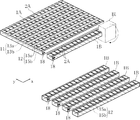
まず、図1に示すように、基板1Aを用意する。基板1Aは、たとえばNi−Cu系合金、Cu−Mn系合金、Ni−Cr系合金からなる。この基板1Aの表面側に複数の溝13aおよび複数の溝15aを形成する。複数の溝13aは、方向x(第1方向)に延びており、方向xと直角である方向y(第2方向)において等チッピで配置されている。また、図2に示すように、溝13aは、方向xにおいて一方から他方に向けて深さが線形的に深くなっている。複数の溝15aは、方向yに延びており、方向xにおいて等ピッチで配置されている。複数の溝15aの深さは、一定とされている。
First, as shown in FIG. 1, a
複数の溝13aおよび複数の溝15aを形成するには、たとえばレーザ光を用いる。このレーザ光としては、たとえばYAGレーザ光、グリーンレーザ光、UVレーザ光を用いる。複数の溝13aを形成する場合、方向xに沿ってレーザ光を複数回走査する。溝13aの深さを方向xに沿って線形的に変化させるには、レーザ光の出力あるいは走査速度を徐々に変化させればよい。また、方向yに沿ってレーザ光を複数回走査することにより、複数の溝15aが得られる。
For example, laser light is used to form the plurality of
次に、基板1Aの裏面側に、複数の溝13bおよび複数の溝15bを形成する。溝13bは、方向xに延びており、溝13aと方向yにおける位置がほぼ一致している。溝13aの深さは、溝13aと同じ方向に線形的に深くなっている。溝15bは、方向yに延びており、溝15aと方向xにおける位置が一致している。溝15bの深さは、一定とされている。複数の溝13bおよび複数の溝15bを形成するには、上述したレーザ光を用いる。以上の工程により、基板1Aに複数の第1切断容易部11と複数の第2切断容易部12とが形成される。第1切断容易部11は、1対の溝13a,13bによって構成されている。第2切断容易部12は、1対の溝15a,15bによって構成されている。
Next, a plurality of
次いで、図3に示すように、複数の導電体層2Aを形成する。複数の導電体層2Aは、各々が溝13aを覆うように方向xに延びており、方向yにおいて等ピッチで配列されている。複数の導電体層2Aは、たとえばCuメッキを施すことにより形成する。
Next, as shown in FIG. 3, a plurality of
次に、図4に示すように、第1切断容易部11に沿って基板1Aを折り曲げることにより、基板1Aを切断する。この切断には、たとえばコの字状の分割ブロックBlを用いる。分割ブロックBlを、基板1Aの方向xに延びる一端に係合させる。係合させる位置は、方向xにおいて溝13a,13bの深さが深くなっている側の端部付近とする。分割ブロックBlによって基板1Aに曲げモーメントを加えると、上記一端に最も近い第1切断容易部11において基板1Aが切断され、その一方が帯状部材1Bとなる。この切断においては、溝13a,13bのうち深さが最も深くなっている端部から亀裂が発生する。この亀裂が第1切断容易部11に沿って進展する。そして、基板1Aの残存部の断面積が曲げモーメントに抗しきれなくなると、最終破断に至る。この最終破断面18は、溝13a,13bの深さが浅くなっている側の端部に再現性よく生じる。この分割ブロックBlを用いた切断を繰り返すことにより、基板1Aを複数の帯状部材1Bに分割する。
Next, as shown in FIG. 4, the substrate 1 </ b> A is cut by bending the substrate 1 </ b> A along the first easy-to-cut
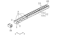
次いで、図5に示すように、帯状部材1Bを第2切断容易部12に沿って順次切断することにより、複数のチップ抵抗器Aが得られる。帯状部材1Bを切断した結果、最終破断面18を含むこととなった部分は、最終製品とすることなく、廃棄する。
Next, as shown in FIG. 5, a plurality of chip resistors A are obtained by sequentially cutting the belt-like member 1 </ b> B along the second easy-to-
図6は、本実施形態の製造方法によって得られるチップ抵抗器の一例を示している。チップ抵抗器Aは、抵抗体1と1対の電極2とを備えている。抵抗体1は、チップ抵抗器Aの電気抵抗を生じる部分である。1対の電極2は、チップ抵抗器Aを面実装するのに用いられる部分であり、導電体層2Aが分割されることにより形成されている。抵抗体1の方向y視における断面積と1対の電極2の間隔とによって、チップ抵抗器Aの抵抗値が規定される。
FIG. 6 shows an example of a chip resistor obtained by the manufacturing method of this embodiment. The chip resistor A includes a resistor 1 and a pair of
チップ抵抗器Aのうち方向yを向く側面には、溝13a,13bの形状が現れている。溝13a,13bがあった部分は、レーザ光によって加工された部分であるため、比較的平滑である。一方、溝13a,13bに挟まれた部分は、折り曲げ加工によって切断された部分であるため、若干粗い面となっている。これと同様に、チップ抵抗器Aのうち方向xを向く側面には、溝15a,15bの形状が現れている。
On the side surface of the chip resistor A facing the direction y, the shapes of the
次に、チップ抵抗器Aの製造方法の作用について説明する。 Next, the operation of the manufacturing method of the chip resistor A will be described.
本実施形態によれば、基板1Aを切断することにより生じる最終破断面18を、帯状部材1Bの端部付近に確実に生じさせることができる。帯状部材1Bの端部付近は、たとえば帯状部材1Bをさらに切断することにより複数のチップ抵抗器Aを形成する工程において、帯状部材1Bを把持するために用いられる部分であり、廃棄されることが多い。このような部分に最終破断面18を位置させることにより、最終製品となるチップ抵抗器Aに最終破断面18が含まれることを回避することが可能である。したがって、チップ抵抗器Aの歩留まりを向上させることができる。
According to the present embodiment, the
本実施形態においては、分割ブロックBlを、基板1Aに対して溝13a,13bの深さが深くなっている側に係合させているが、これと異なり、基板1Aに対して溝13a,13bの深さが浅くなっている側に係合させてもよい。このような実施形態は、切断しようとする第1切断容易部11に対して分割ブロックBlの端部を十分に正確に位置させることが可能な場合に有効である。分割ブロックBlによって、溝13a,13bの深さが浅い側から発生した亀裂は、溝13a,13bの深さが深くなっている側に向かって確実に進展する。したがって、このような実施形態によっても最終破断面18を帯状部材1Bの端部付近に位置させることが可能であり、チップ抵抗器Aの歩留まりを向上させることができる。
In the present embodiment, the divided block Bl is engaged with the
図7〜図11は、本発明の他の実施形態を示している。なお、これらの図において、上記実施形態と同一または類似の要素には、上記実施形態と同一の符号を付しており、適宜説明を省略する。 7 to 11 show other embodiments of the present invention. In these drawings, the same or similar elements as those in the above embodiment are denoted by the same reference numerals as those in the above embodiment, and description thereof will be omitted as appropriate.
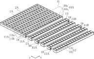
まず、図7に示すように、基板1Aに複数の第1切断容易部11A,11Bと複数の第2切断容易部12とを形成する。第1切断容易部11Aは、溝13a,13bによって構成されており、第1切断容易部11Bは、溝14a,14bによって構成されている。図8に示すように、溝13a,13bは、左方から右方に向かうほど深さが深くなっている。一方、図9に示すように、溝14a,14bは、溝13a,13bとは反対に、右方から左方に向かうほど深さが深くなっている。複数の第1切断容易部11Aと複数の第1切断容易部11Bとは、方向yにおいて交互に配置されている。複数の第2切断容易部12は、方向yに延びており、方向xにおいて等ピッチで配置されている。
First, as shown in FIG. 7, a plurality of first easy-to-
次に、図10に示すように、基板1Aに複数の導電体層2Aを形成した後に、第1切断容易部11A,11Bに沿って基板1Aを切断する。この切断には、たとえば分割ローラRlを用いる。基板1Aをテーブルあるいは他のローラ(いずれも図示略)によって下方から支持した状態で、分割ローラRlを基板1Aに押し付ける。図11は、分割ローラRlによる切断作業の一過程を示している。これは、ある第1切断容易部11Aに沿って切断した後に、これに隣り合う第1切断容易部11Bに沿って基板1を切断する状態である。このとき、分割ローラRlの方向yにおける位置を第1切断容易部11Bに合わせる。この状態で分割ローラRlから基板1Aに力を負荷することにより、第1切断容易部11Bに沿って基板1Aが切断される。この切断を順次繰り返すことにより、複数の帯状部材1Bを形成する。そして、帯状部材1Bを第2切断容易部12に沿って切断することにより、図6に示す複数のチップ抵抗器Aが得られる。
Next, as shown in FIG. 10, after forming a plurality of
本実施形態によれば、図10に示すように、最終破断面18は、帯状部材1Bの両端のいずれかに生じることとなる。帯状部材1Bの両端部分は、もともと廃棄されることが多い部分である。このため、最終製品となるチップ抵抗器Aに最終破断面18が含まれることを回避することが可能であり、チップ抵抗器Aの歩留まりを向上させることができる。
According to the present embodiment, as shown in FIG. 10, the
また、図11に示すように、第1切断容易部11Bに沿って切断しようとするときに、分割ローラRlがこの第1切断容易部11Bから若干位置ずれする場合がある。分割ローラRlがたとえば隣り合う第1切断容易部11A寄りに位置ずれした場合、第1切断容易部11Bに負荷されるべき力の一部が隣り合う第1切断容易部11Aに負荷される。しかし、第1切断容易部11Bの溝14a,14bの深さが深い側の端部においては、隣り合う第1切断容易部11Aの溝13a,13bの深さは浅い側となっている。このため、分割ローラRlが若干位置ずれしたとしても、深さが深い溝14a,14bから選択的に亀裂が発生し、隣り合う第1切断容易部11Aに亀裂が発生するおそれが少ない。したがって、方向yに配置された第1切断容易部11A,11Bに沿って、順序良く基板1Aを切断することが可能である。
Further, as shown in FIG. 11, when the cutting is performed along the first easy-to-cut
本発明に係るチップ抵抗器の製造方法は、上述した実施形態に限定されるものではない。本発明に係るチップ抵抗器の製造方法の具体的な構成は、種々に設計変更自在である。 The manufacturing method of the chip resistor according to the present invention is not limited to the above-described embodiment. The specific configuration of the chip resistor manufacturing method according to the present invention can be varied in design in various ways.
本発明で言う第1切断容易部を構成する溝の深さは、長手方向に沿って線形的に変化するものに限定されず、一方から他方に向けて深さが単調に変化しているものであればよい。また、基板の表裏面に形成された1対の溝のうち、一方の溝のみの深さが長手方向において単調に変化する構成であっても良い。さらに、第1切断容易部を構成する溝は、基板の片側に設けられていてもよい。 The depth of the groove constituting the first easy-to-cut portion according to the present invention is not limited to the one that linearly changes along the longitudinal direction, and the depth monotonously changes from one to the other. If it is. Moreover, the structure from which the depth of only one groove | channel changes monotonously in a longitudinal direction among a pair of groove | channels formed in the front and back of a board | substrate may be sufficient. Further, the groove constituting the first easy-to-cut portion may be provided on one side of the substrate.
A チップ抵抗器
Bl 分割ブロック
Rl 分割ローラ
x (第1)方向
y (第2)方向
1 抵抗体
1A 基板
1B 帯状部材
2 電極
2A 導電体層
11,11A,11B 第1切断容易部
12 第2切断容易部
13a,13b,14a,14b,15a,15b 溝
18 最終破断面
A Chip resistor Bl Dividing block Rl Dividing roller x (First) direction y (Second) direction 1
Claims (2)
上記基板を上記複数の第1切断容易部に沿って切断することにより、複数の帯状部材に分割する工程と、
上記帯状部材を上記複数の第2切断容易部に沿って切断することにより、複数のチップ抵抗器に分割する工程と、
を有するチップ抵抗器の製造方法であって、
上記第1切断容易部は、上記基板の表面側および裏面側の少なくともいずれかに形成された溝からなり、
上記溝の深さが、上記第1切断容易部が延びる方向において一方から他方に向けて単調増加または単調減少していることを特徴とする、チップ抵抗器の製造方法。 Forming a substrate made of a resistor material and having a plurality of first easy-to-cut parts extending in a first direction and a plurality of second easy-to-cut parts extending in a second direction perpendicular to the first direction; ,
Cutting the substrate along the plurality of first easy-to-cut portions to divide the substrate into a plurality of strip-shaped members;
Dividing the strip-shaped member along the plurality of second easy-to-cut portions to divide into a plurality of chip resistors;
A chip resistor manufacturing method comprising:
The first easy-to-cut portion is a groove formed on at least one of the front surface side and the back surface side of the substrate,
The method of manufacturing a chip resistor, wherein the depth of the groove monotonously increases or monotonously decreases from one to the other in the direction in which the first easy-to-cut portion extends.
Priority Applications (1)
| Application Number | Priority Date | Filing Date | Title |
|---|---|---|---|
| JP2007074736A JP5208436B2 (en) | 2007-03-22 | 2007-03-22 | Manufacturing method of chip resistor |
Applications Claiming Priority (1)
| Application Number | Priority Date | Filing Date | Title |
|---|---|---|---|
| JP2007074736A JP5208436B2 (en) | 2007-03-22 | 2007-03-22 | Manufacturing method of chip resistor |
Publications (2)
| Publication Number | Publication Date |
|---|---|
| JP2008235670A JP2008235670A (en) | 2008-10-02 |
| JP5208436B2 true JP5208436B2 (en) | 2013-06-12 |
Family
ID=39908098
Family Applications (1)
| Application Number | Title | Priority Date | Filing Date |
|---|---|---|---|
| JP2007074736A Expired - Fee Related JP5208436B2 (en) | 2007-03-22 | 2007-03-22 | Manufacturing method of chip resistor |
Country Status (1)
| Country | Link |
|---|---|
| JP (1) | JP5208436B2 (en) |
Families Citing this family (3)
| Publication number | Priority date | Publication date | Assignee | Title |
|---|---|---|---|---|
| JP5543146B2 (en) | 2009-07-27 | 2014-07-09 | ローム株式会社 | Chip resistor and manufacturing method of chip resistor |
| JP5791450B2 (en) * | 2011-09-28 | 2015-10-07 | 京セラ株式会社 | Multi-cavity wiring board and wiring board |
| CN116631716A (en) * | 2023-07-18 | 2023-08-22 | 合肥矽迈微电子科技有限公司 | Manufacturing method of variable resistor device |
Family Cites Families (4)
| Publication number | Priority date | Publication date | Assignee | Title |
|---|---|---|---|---|
| JPH04509U (en) * | 1990-04-17 | 1992-01-06 | ||
| JP3029821B2 (en) * | 1998-06-04 | 2000-04-10 | ローム株式会社 | Substrate for electronic components |
| JP2000238034A (en) * | 1999-02-18 | 2000-09-05 | Rohm Co Ltd | Ceramic board and separating method therefor |
| JP2007049071A (en) * | 2005-08-12 | 2007-02-22 | Rohm Co Ltd | Chip resistor and manufacturing method thereof |
-
2007
- 2007-03-22 JP JP2007074736A patent/JP5208436B2/en not_active Expired - Fee Related
Also Published As
| Publication number | Publication date |
|---|---|
| JP2008235670A (en) | 2008-10-02 |
Similar Documents
| Publication | Publication Date | Title |
|---|---|---|
| KR101536068B1 (en) | Wiring substrate, multi-pattern wiring substrate, and manufacturing method therefor | |
| US8563343B2 (en) | Method of manufacturing laser diode device | |
| JP5208436B2 (en) | Manufacturing method of chip resistor | |
| JP2008218621A (en) | Chip resistor and its manufacturing method | |
| KR20180050626A (en) | Method of cutting layered ceramic substrate | |
| CN115884952A (en) | Method for producing a cermet substrate and cermet substrate produced by means of said method | |
| TWI534841B (en) | Method of manufacturing wafer resistors | |
| WO2004001774A1 (en) | Chip resistor having low resistance and its producing method | |
| US9942995B2 (en) | Method for producing a metal core substrate having improved edge insulating properties | |
| JP2007049071A (en) | Chip resistor and manufacturing method thereof | |
| JP5014767B2 (en) | Manufacturing method of chip resistor | |
| JP5282739B2 (en) | Electronic component and mounting method thereof | |
| WO2014045862A1 (en) | Flexible multilayer substrate | |
| JP6892339B2 (en) | Resistor | |
| WO2012144114A1 (en) | Wiring board, multi-pattern wiring board, and method for producing same | |
| JP2007242939A (en) | Manufacturing method of ceramic multilayer substrate | |
| JP4277633B2 (en) | Manufacturing method of chip resistor | |
| JP4542967B2 (en) | Manufacturing method of chip resistor | |
| JP6749752B2 (en) | Chip resistor and method of manufacturing chip resistor | |
| JP5891342B2 (en) | Manufacturing method of chip resistor | |
| JP2003347684A (en) | Ceramic substrate and manufacturing method therefor | |
| JP4881557B2 (en) | Manufacturing method of chip resistor | |
| JP4867325B2 (en) | Manufacturing method of chip-type network electronic component | |
| JP2020098806A (en) | Chip resistor and manufacturing method thereof | |
| JP2005093541A (en) | Piezoelectric element and its manufacturing method |
Legal Events
| Date | Code | Title | Description |
|---|---|---|---|
| A621 | Written request for application examination |
Free format text: JAPANESE INTERMEDIATE CODE: A621 Effective date: 20100122 |
|
| A977 | Report on retrieval |
Free format text: JAPANESE INTERMEDIATE CODE: A971007 Effective date: 20120717 |
|
| A131 | Notification of reasons for refusal |
Free format text: JAPANESE INTERMEDIATE CODE: A131 Effective date: 20120724 |
|
| A521 | Written amendment |
Free format text: JAPANESE INTERMEDIATE CODE: A523 Effective date: 20120920 |
|
| A131 | Notification of reasons for refusal |
Free format text: JAPANESE INTERMEDIATE CODE: A131 Effective date: 20121204 |
|
| A521 | Written amendment |
Free format text: JAPANESE INTERMEDIATE CODE: A523 Effective date: 20130201 |
|
| TRDD | Decision of grant or rejection written | ||
| A01 | Written decision to grant a patent or to grant a registration (utility model) |
Free format text: JAPANESE INTERMEDIATE CODE: A01 Effective date: 20130219 |
|
| A61 | First payment of annual fees (during grant procedure) |
Free format text: JAPANESE INTERMEDIATE CODE: A61 Effective date: 20130220 |
|
| FPAY | Renewal fee payment (event date is renewal date of database) |
Free format text: PAYMENT UNTIL: 20160301 Year of fee payment: 3 |
|
| R150 | Certificate of patent or registration of utility model |
Ref document number: 5208436 Country of ref document: JP Free format text: JAPANESE INTERMEDIATE CODE: R150 Free format text: JAPANESE INTERMEDIATE CODE: R150 |
|
| LAPS | Cancellation because of no payment of annual fees |