JP5191565B2 - Centrifugal dehydration method and centrifugal dehydration apparatus - Google Patents
Centrifugal dehydration method and centrifugal dehydration apparatus Download PDFInfo
- Publication number
- JP5191565B2 JP5191565B2 JP2011232090A JP2011232090A JP5191565B2 JP 5191565 B2 JP5191565 B2 JP 5191565B2 JP 2011232090 A JP2011232090 A JP 2011232090A JP 2011232090 A JP2011232090 A JP 2011232090A JP 5191565 B2 JP5191565 B2 JP 5191565B2
- Authority
- JP
- Japan
- Prior art keywords
- bowl
- centrifugal
- straight
- cake
- screw conveyor
- Prior art date
- Legal status (The legal status is an assumption and is not a legal conclusion. Google has not performed a legal analysis and makes no representation as to the accuracy of the status listed.)
- Active
Links
- 230000018044 dehydration Effects 0.000 title claims description 46
- 238000006297 dehydration reaction Methods 0.000 title claims description 46
- 238000000034 method Methods 0.000 title claims description 37
- 239000007788 liquid Substances 0.000 claims description 100
- 238000012545 processing Methods 0.000 claims description 40
- 230000002093 peripheral effect Effects 0.000 claims description 31
- 229920000642 polymer Polymers 0.000 claims description 25
- 238000000926 separation method Methods 0.000 claims description 21
- 238000011144 upstream manufacturing Methods 0.000 claims description 13
- 230000004323 axial length Effects 0.000 claims description 10
- 239000007787 solid Substances 0.000 claims description 10
- 230000003247 decreasing effect Effects 0.000 claims description 9
- XLYOFNOQVPJJNP-UHFFFAOYSA-N water Substances O XLYOFNOQVPJJNP-UHFFFAOYSA-N 0.000 description 43
- 208000005156 Dehydration Diseases 0.000 description 40
- 230000000694 effects Effects 0.000 description 37
- 230000000052 comparative effect Effects 0.000 description 32
- 239000010802 sludge Substances 0.000 description 24
- 230000007423 decrease Effects 0.000 description 11
- HMUNWXXNJPVALC-UHFFFAOYSA-N 1-[4-[2-(2,3-dihydro-1H-inden-2-ylamino)pyrimidin-5-yl]piperazin-1-yl]-2-(2,4,6,7-tetrahydrotriazolo[4,5-c]pyridin-5-yl)ethanone Chemical compound C1C(CC2=CC=CC=C12)NC1=NC=C(C=N1)N1CCN(CC1)C(CN1CC2=C(CC1)NN=N2)=O HMUNWXXNJPVALC-UHFFFAOYSA-N 0.000 description 6
- 238000009826 distribution Methods 0.000 description 5
- QAOWNCQODCNURD-UHFFFAOYSA-L Sulfate Chemical compound [O-]S([O-])(=O)=O QAOWNCQODCNURD-UHFFFAOYSA-L 0.000 description 4
- 230000009471 action Effects 0.000 description 4
- 238000003825 pressing Methods 0.000 description 4
- 239000010865 sewage Substances 0.000 description 4
- 238000012360 testing method Methods 0.000 description 4
- 230000005540 biological transmission Effects 0.000 description 3
- 230000008859 change Effects 0.000 description 3
- 238000010586 diagram Methods 0.000 description 3
- 230000006872 improvement Effects 0.000 description 3
- 238000007373 indentation Methods 0.000 description 3
- 239000000126 substance Substances 0.000 description 3
- 238000012795 verification Methods 0.000 description 3
- WZFUQSJFWNHZHM-UHFFFAOYSA-N 2-[4-[2-(2,3-dihydro-1H-inden-2-ylamino)pyrimidin-5-yl]piperazin-1-yl]-1-(2,4,6,7-tetrahydrotriazolo[4,5-c]pyridin-5-yl)ethanone Chemical compound C1C(CC2=CC=CC=C12)NC1=NC=C(C=N1)N1CCN(CC1)CC(=O)N1CC2=C(CC1)NN=N2 WZFUQSJFWNHZHM-UHFFFAOYSA-N 0.000 description 2
- YLZOPXRUQYQQID-UHFFFAOYSA-N 3-(2,4,6,7-tetrahydrotriazolo[4,5-c]pyridin-5-yl)-1-[4-[2-[[3-(trifluoromethoxy)phenyl]methylamino]pyrimidin-5-yl]piperazin-1-yl]propan-1-one Chemical compound N1N=NC=2CN(CCC=21)CCC(=O)N1CCN(CC1)C=1C=NC(=NC=1)NCC1=CC(=CC=C1)OC(F)(F)F YLZOPXRUQYQQID-UHFFFAOYSA-N 0.000 description 2
- 239000008186 active pharmaceutical agent Substances 0.000 description 2
- 238000005054 agglomeration Methods 0.000 description 2
- 230000002776 aggregation Effects 0.000 description 2
- 239000000701 coagulant Substances 0.000 description 2
- 230000006835 compression Effects 0.000 description 2
- 238000007906 compression Methods 0.000 description 2
- 238000007596 consolidation process Methods 0.000 description 2
- 238000011038 discontinuous diafiltration by volume reduction Methods 0.000 description 2
- 238000002474 experimental method Methods 0.000 description 2
- 239000008394 flocculating agent Substances 0.000 description 2
- 239000010842 industrial wastewater Substances 0.000 description 2
- 238000011084 recovery Methods 0.000 description 2
- 238000011160 research Methods 0.000 description 2
- 238000003756 stirring Methods 0.000 description 2
- 238000005406 washing Methods 0.000 description 2
- 238000004065 wastewater treatment Methods 0.000 description 2
- OHVLMTFVQDZYHP-UHFFFAOYSA-N 1-(2,4,6,7-tetrahydrotriazolo[4,5-c]pyridin-5-yl)-2-[4-[2-[[3-(trifluoromethoxy)phenyl]methylamino]pyrimidin-5-yl]piperazin-1-yl]ethanone Chemical compound N1N=NC=2CN(CCC=21)C(CN1CCN(CC1)C=1C=NC(=NC=1)NCC1=CC(=CC=C1)OC(F)(F)F)=O OHVLMTFVQDZYHP-UHFFFAOYSA-N 0.000 description 1
- LDXJRKWFNNFDSA-UHFFFAOYSA-N 2-(2,4,6,7-tetrahydrotriazolo[4,5-c]pyridin-5-yl)-1-[4-[2-[[3-(trifluoromethoxy)phenyl]methylamino]pyrimidin-5-yl]piperazin-1-yl]ethanone Chemical compound C1CN(CC2=NNN=C21)CC(=O)N3CCN(CC3)C4=CN=C(N=C4)NCC5=CC(=CC=C5)OC(F)(F)F LDXJRKWFNNFDSA-UHFFFAOYSA-N 0.000 description 1
- 238000009825 accumulation Methods 0.000 description 1
- 230000008901 benefit Effects 0.000 description 1
- 230000037237 body shape Effects 0.000 description 1
- 238000005119 centrifugation Methods 0.000 description 1
- 238000005345 coagulation Methods 0.000 description 1
- 230000015271 coagulation Effects 0.000 description 1
- 238000004891 communication Methods 0.000 description 1
- 239000002131 composite material Substances 0.000 description 1
- 230000007547 defect Effects 0.000 description 1
- 238000000151 deposition Methods 0.000 description 1
- 238000007599 discharging Methods 0.000 description 1
- 238000005189 flocculation Methods 0.000 description 1
- 230000016615 flocculation Effects 0.000 description 1
- 229910010272 inorganic material Inorganic materials 0.000 description 1
- 239000011147 inorganic material Substances 0.000 description 1
- 230000014759 maintenance of location Effects 0.000 description 1
- 239000000203 mixture Substances 0.000 description 1
- 239000005416 organic matter Substances 0.000 description 1
- 230000002265 prevention Effects 0.000 description 1
- 230000008569 process Effects 0.000 description 1
- 230000009467 reduction Effects 0.000 description 1
- 238000007789 sealing Methods 0.000 description 1
- 239000013049 sediment Substances 0.000 description 1
Images


Classifications
-
- B—PERFORMING OPERATIONS; TRANSPORTING
- B04—CENTRIFUGAL APPARATUS OR MACHINES FOR CARRYING-OUT PHYSICAL OR CHEMICAL PROCESSES
- B04B—CENTRIFUGES
- B04B1/00—Centrifuges with rotary bowls provided with solid jackets for separating predominantly liquid mixtures with or without solid particles
- B04B1/20—Centrifuges with rotary bowls provided with solid jackets for separating predominantly liquid mixtures with or without solid particles discharging solid particles from the bowl by a conveying screw coaxial with the bowl axis and rotating relatively to the bowl
-
- B—PERFORMING OPERATIONS; TRANSPORTING
- B04—CENTRIFUGAL APPARATUS OR MACHINES FOR CARRYING-OUT PHYSICAL OR CHEMICAL PROCESSES
- B04B—CENTRIFUGES
- B04B11/00—Feeding, charging, or discharging bowls
- B04B11/08—Skimmers or scrapers for discharging ; Regulating thereof
-
- C—CHEMISTRY; METALLURGY
- C02—TREATMENT OF WATER, WASTE WATER, SEWAGE, OR SLUDGE
- C02F—TREATMENT OF WATER, WASTE WATER, SEWAGE, OR SLUDGE
- C02F11/00—Treatment of sludge; Devices therefor
- C02F11/12—Treatment of sludge; Devices therefor by de-watering, drying or thickening
-
- B—PERFORMING OPERATIONS; TRANSPORTING
- B04—CENTRIFUGAL APPARATUS OR MACHINES FOR CARRYING-OUT PHYSICAL OR CHEMICAL PROCESSES
- B04B—CENTRIFUGES
- B04B1/00—Centrifuges with rotary bowls provided with solid jackets for separating predominantly liquid mixtures with or without solid particles
- B04B1/20—Centrifuges with rotary bowls provided with solid jackets for separating predominantly liquid mixtures with or without solid particles discharging solid particles from the bowl by a conveying screw coaxial with the bowl axis and rotating relatively to the bowl
- B04B2001/2091—Configuration of solids outlets
Landscapes
- Life Sciences & Earth Sciences (AREA)
- Hydrology & Water Resources (AREA)
- Engineering & Computer Science (AREA)
- Environmental & Geological Engineering (AREA)
- Water Supply & Treatment (AREA)
- Chemical & Material Sciences (AREA)
- Organic Chemistry (AREA)
- Centrifugal Separators (AREA)
- Drying Of Solid Materials (AREA)
- Treatment Of Sludge (AREA)
Description
本発明は、下水処理や工業排水処理、あるいは化学・食品工業用諸生産品において、処理液を、遠心力により固液分離し固形物及び分離液の回収を行うようにした遠心脱水方法及び遠心脱水装置に関するものである。 The present invention relates to a centrifugal dehydration method and a centrifugal method in which a treatment liquid is separated into solid and liquid by centrifugal force to recover a solid and a separated liquid in various products for sewage treatment, industrial wastewater treatment or chemical / food industry. The present invention relates to a dehydrator.
従来、汚泥等(以下、処理液と称する)を遠心力により固液分離するのにデカンタ型遠心脱水装置が広く使用されている。従来のデカンタ型遠心脱水装置は、ボウル円錐部では回転中心からの距離(径)が短くなるため、遠心力が弱くなり含水率が高まってしまう現象が見られる等の欠点があり、本出願人らはこのような従来のデカンタ型遠心脱水装置の欠点を解消するものとして、先に直胴型遠心脱水装置を提供した(特許文献1)。該直胴型遠心脱水装置は、ボウルの内周壁がその回転軸に沿って延在する円筒形を形成し、沈殿した重成分をボウル外へ排出するための排出経路を前記ボウルの一端壁内に設け、排出経路のボウルの開口がボウル内周壁近傍に設けられるとともに、排出経路が排出量を制限する絞り通路となっており、これによって排出経路の開口近傍に圧密状態の脱水ケーキの堆積層を形成させ、絞り通路の排出抵抗によって形成される堆積層の厚さに応じて脱水ケーキに作用する遠心水頭圧と、スクリューコンベアの搬送力によって、排出経路を介し前記圧密状態の脱水ケーキが直接排出されることを特徴とするものである。これにより、ボウル内の脱水ケーキの堆積層のうち、最も高い圧密作用を受けている部分のみを直接排出するので、脱水ケーキの含水率を従前の遠心脱水装置に例を見ないほどに下げることができた。 Conventionally, a decanter type centrifugal dehydration apparatus has been widely used for solid-liquid separation of sludge and the like (hereinafter referred to as a treatment liquid) by centrifugal force. The conventional decanter type centrifugal dewatering device has the disadvantage that the centrifugal force is weakened and the water content is increased because the distance (diameter) from the center of rotation is shortened in the bowl cone part. Have previously provided a straight barrel type centrifugal dewatering device (Patent Document 1) as a solution to the disadvantages of the conventional decanter type centrifugal dewatering device. The straight barrel centrifugal dewatering device has a cylindrical shape in which the inner peripheral wall of the bowl extends along the rotation axis thereof, and a discharge path for discharging the precipitated heavy components to the outside of the bowl is provided in the one end wall of the bowl. The discharge path bowl opening is provided in the vicinity of the inner peripheral wall of the bowl, and the discharge path serves as a throttle path for limiting the discharge amount. The dewatered cake in the compacted state is directly passed through the discharge path by the centrifugal head pressure acting on the dewatered cake according to the thickness of the deposited layer formed by the discharge resistance of the throttle passage and the conveying force of the screw conveyor. It is characterized by being discharged. As a result, only the portion of the dehydrated cake deposit layer in the bowl that is receiving the highest consolidation action is directly discharged, so the moisture content of the dehydrated cake is lowered to an unprecedented level in conventional centrifugal dehydrators. I was able to.
一方、脱水効果を高めるために、脱水装置の上記のような構造・機能的な改良と共に、処理液に高分子凝集剤又は無機凝集剤あるいはそれら両方を添加してフロックを形成して分離・脱水処理することが行なわれている。これらの凝集剤の添加方法は脱水機のタイプや処理液の種類に応じて異なり、デカンタ型の遠心脱水機で固液分離する際の凝集剤の具体的な添加方法として、複合管により内胴の汚泥供給室に汚泥と共に高分子凝集剤を供給する方法(例えば特許文献2、3参照)が一般的であるが、予め外部の攪拌槽内で汚泥に高分子凝集剤を添加攪拌して凝集フロックを生成させたものを内胴の汚泥供給室に供給し、且つ外胴内周のテーパー部を脱水されつつ小径側へ移動する汚泥堆積物に内胴内から無機凝集剤を添加するいわゆる二液法(特許文献4)、あるいは無機凝集剤と高分子凝集剤が供給された汚泥を遠心脱水装置内で固液分離が進んだ分離汚泥に無機凝集剤を再注入する方法(特許文献5)等が提案されている。
On the other hand, in order to enhance the dehydration effect, in addition to the above structural and functional improvements of the dehydrator, a polymer flocculant and / or an inorganic flocculant is added to the treatment liquid to form a floc for separation / dehydration. Processing is done. The method for adding these flocculants varies depending on the type of dehydrator and the type of treatment liquid. As a specific method for adding the flocculant when solid-liquid separation is performed with a decanter type centrifugal dehydrator, a composite tube is used as the inner cylinder. A method of supplying a polymer flocculant together with sludge to a sludge supply chamber (see, for example,
これらデカンタ型遠心脱水機において、特許文献3の方法では、脱水汚泥の含水率を82%まで低下させることができることを見出した旨記載されている。また、特許文献4の方法では、実験室で卓上遠心脱水機を用いて下水消化汚泥の脱水ケーキ含水率を72.7%に低下させたこと、特許文献5の方法では、同じく下水消化汚泥(汚泥濃度1.5%)、処理量1.5m3/h、遠心効果2500Gで行なった結果、脱水ケーキ含水率75.0%となったことが示されている。
以上のように、従来のデカンタ型遠心脱水機の脱水ケーキ含水率は、小型機で例えば消化汚泥の場合で、実機で最大で75%で程度しか低下させることができなかった。
In these decanter type centrifugal dehydrators, it is described that the method of
As described above, the moisture content of the dehydrated cake of the conventional decanter type centrifugal dehydrator can be reduced only by about 75% at the maximum in the case of a digested sludge in a small machine, for example.
前記提案した直胴型遠心脱水装置は、機内脱水ケーキの堆積層のうち、最も高い圧密作用を受けている部分のみを直接排出するので、脱水ケーキの含水率を従来の遠心脱水装置に比べて飛躍的に低下させることができたが、スクリューコンベアの内筒先端から壁が半径方向外方に立ち上がって排出経路入口まで延びているため、脱水ケーキの堆積層はボウルの前端部分の壁に当たると共に、絞り通路となっている排出経路の排出抵抗により、大きな堆積層をこの部分に形成し、この部分の機内脱水ケーキの高遠心場から排出経路への移動が容易でなく運転負荷が増大する傾向にあると共に、スクリューコンベアの内筒側の低遠心力部の水分が抜けにくいという問題点があった。 The proposed straight-cylinder centrifugal dewatering device directly discharges only the part of the in-machine dewatered cake pile that is subjected to the highest consolidation action, so the water content of the dewatered cake is higher than that of the conventional centrifugal dewatering device. Although the wall could rise dramatically from the tip of the inner cylinder of the screw conveyor and extend to the outlet of the discharge path, the dehydrated cake piled up against the front end of the bowl. Due to the discharge resistance of the discharge path that is the throttle passage, a large sediment layer is formed in this part, and the movement of the dewatered cake in this part from the high centrifugal field to the discharge path is not easy and the operating load tends to increase In addition, there is a problem that moisture in the low centrifugal force portion on the inner cylinder side of the screw conveyor is difficult to escape.
一方、脱水効果をさらに高めるために、特許文献4、5に示しているデカンタ型遠心脱水機と同様に高分子凝集剤に加えて無機凝集剤を添加する二液法によってさらに脱水効果を向上させることが考えられるが、無機凝集剤、例えばポリ硫酸第二鉄は水の中では凝集効果が薄くある程度脱水された状態、即ち機内添加でないと効果が少ない。しかしながら、従来の直胴型遠心脱水装置においては、前記のようにボウルの前端部分が垂直壁であり、その箇所に脱水ケーキの堆積層が形成されるため、機内で無機凝集剤を添加するとこの堆積層で固まってしまい排出できなくなって機内閉塞を起こし運転不能となるため、従来の直胴型遠心脱水機では無機凝集剤の後添加による二液添加法は採用できないという問題点があった。
On the other hand, in order to further enhance the dehydration effect, the dehydration effect is further improved by a two-component method in which an inorganic flocculant is added in addition to the polymer flocculant in the same manner as the decanter type centrifugal dehydrator shown in
そこで、本発明は、直胴型遠心脱水装置の前記問題点を解決しようとするものであり、ボウル内の脱水ケーキからの水分の抜けが容易でより脱水効果を高めると共に、圧搾効率を高め装置内負荷の軽減を図ることができる遠心脱水方法及び直胴型遠心脱水機を提供することを第1の目的とし、且つ無機凝集剤の後添加による二液添加法が採用できてより脱水効果を高めることができる遠心脱水方法及び直胴型遠心脱水機を提供することを第2の目的とするものである。 Therefore, the present invention is intended to solve the above-mentioned problems of the straight-cylinder centrifugal dewatering device, and it is easy to remove moisture from the dewatered cake in the bowl, thereby improving the dewatering effect and increasing the compression efficiency. The first object is to provide a centrifugal dehydration method and a straight barrel type centrifugal dehydrator that can reduce the internal load, and a two-component addition method by post-addition of an inorganic flocculant can be adopted to further increase the dehydration effect. It is a second object of the present invention to provide a centrifugal dehydration method and a straight barrel centrifugal dehydrator that can be enhanced.
上記問題点を解決する本発明の直胴型遠心脱水方法は、一方向に回転する直胴型のボウルと、該ボウル内で該ボウルと同軸に回転速度差を有して同方向に回転する回転胴の外周に螺旋翼を巻装してなるスクリューコンベアを有する直胴型遠心脱水装置により、処理液を固液分離して固形物及び分離液の回収を行なう直胴型遠心脱水装置による遠心脱水方法において、前記直胴型遠心脱水装置は、前記ボウルの内周壁が前記ボウルの回転軸に沿って延在する円筒形を形成し、且つ前記スクリューコンベアの前記回転胴の外周面が、上流側がストレートな円周面からなるストレート部と、下流側が前記ストレート部から径大方向に傾斜したテーパー部とから構成され、前記回転胴の処理液供給口から前記テーパー部開始点までのストレート部の軸方向長さL1と、前記回転胴のテーパー部の軸方向長さL2との比L1/L2が1.2〜5.0の範囲であり、且つ前記テーパー部の開始部の傾斜角が5〜30゜の範囲内にあり、前記処理液は、前記回転胴の内部に形成された処理液供給室を介して前記ボウルと前記スクリューコンベアとの間の環状空間に供給され、前記ボウル及び前記スクリューコンベアの回転の遠心力で固液分離されながら分離液は分離液排出口より排出され、脱水ケーキは遠心水頭圧と前記スクリューコンベアの搬送力とにより脱水ケーキ排出経路へ押出してなり、前記脱水ケーキは、前記脱水ケーキ排出経路側に向けて前記テーパー部によって、徐々に高遠心力場に移動させ、かつ脱水ケーキ排出路側に向かって脱水ケーキの通過面積を漸減させて脱水することを特徴とするものである。 A straight barrel centrifugal dewatering method of the present invention that solves the above-mentioned problems is a straight barrel bowl that rotates in one direction, and rotates in the same direction with a rotational speed difference coaxially with the bowl in the bowl. Centrifugation by a straight barrel centrifugal dewatering device that collects solids and separated liquid by separating the processing liquid into solid and liquid by a straight barrel centrifugal dewatering device having a screw conveyor in which spiral blades are wound around the outer periphery of the rotating drum. In the dewatering method, the straight barrel centrifugal dewatering device has a cylindrical shape in which the inner peripheral wall of the bowl extends along the rotation axis of the bowl, and the outer peripheral surface of the rotary drum of the screw conveyor is upstream. The straight portion is composed of a straight circumferential surface and the downstream portion is a tapered portion inclined in a large diameter direction from the straight portion, and the straight portion from the processing liquid supply port of the rotating drum to the tapered portion start point axis The ratio L1 / L2 between the direction length L1 and the axial length L2 of the tapered portion of the rotating drum is in the range of 1.2 to 5.0, and the inclination angle of the start portion of the tapered portion is 5 to 5. Within the range of 30 °, the processing liquid is supplied to an annular space between the bowl and the screw conveyor via a processing liquid supply chamber formed inside the rotary drum, and the bowl and the screw The separated liquid is discharged from the separated liquid discharge port while being separated into solid and liquid by the centrifugal force of the rotation of the conveyor, and the dehydrated cake is extruded to the dehydrated cake discharge path by the centrifugal head pressure and the conveying force of the screw conveyor. The dewatering cake discharge path side is gradually moved to the high centrifugal force field by the tapered portion, and the dewatering cake passage area is gradually decreased toward the dewatering cake discharge path side for dehydration. It is an butterfly.
本発明の直胴型遠心脱水方法において、前記回転胴の処理液供給口から前記テーパー部開始点までのストレート部の軸方向長さL1と、前記回転胴のテーパー部の軸方向長さL2との比L1/L2が1.2〜5.0の範囲とすることによって、ストレート部からの押し込み力が増大し、より含水率を低下させることができ望ましい。 In the straight barrel centrifugal dehydration method of the present invention, the axial length L1 of the straight portion from the processing liquid supply port of the rotating drum to the tapered portion start point, and the axial length L2 of the tapered portion of the rotating drum, By setting the ratio L1 / L2 in the range of 1.2 to 5.0, it is desirable that the pushing force from the straight portion increases and the water content can be further reduced.
前記処理液供給室に処理液と高分子凝集剤を供給する処理液供給工程、前記処理液供給室から前記高分子凝集剤が添加された処理液が回転胴に形成された供給口を介してボウル内周の環状空間に供給され、遠心力により脱水されながら前記スクリューコンベヤにより搬送される前記脱水ケーキに、前記スクリューコンベアの回転胴内方より無機凝集剤を添加する無機凝集剤添加工程を備えていることによって、前記第2の目的を達成することができる。 A treatment liquid supply step for supplying a treatment liquid and a polymer flocculant to the treatment liquid supply chamber, and a treatment liquid to which the polymer flocculant is added from the treatment liquid supply chamber via a supply port formed in a rotary drum An inorganic flocculant addition step of adding an inorganic flocculant to the dewatered cake that is supplied to the annular space around the inner periphery of the bowl and transported by the screw conveyor while being dewatered by centrifugal force is provided from the inside of the rotary drum of the screw conveyor. Therefore, the second object can be achieved.
本発明の直胴型遠心脱水方法において、前記無機凝集剤の供給工程は、前記スクリューコンベアのストレート部の前記供給口から下流側と前記テーパー部上流端との間で、前記脱水ケーキに添加することがテーパー部での脱水ケーキの機内閉塞を防止する上で望ましい。また、前記無機凝集剤の添加は、脱水ケーキ表面と脱水ケーキ内部への添加の組合せにより行なうのが、脱水効率をより高める上で望ましい。 In the straight barrel centrifugal dewatering method of the present invention, the inorganic flocculant supplying step is added to the dehydrated cake between the downstream side of the straight port of the screw conveyor and the upstream end of the tapered portion. This is desirable in order to prevent the dewatered cake from being blocked in the machine at the tapered portion. Further, the addition of the inorganic flocculant is preferably performed by a combination of addition to the surface of the dehydrated cake and the inside of the dehydrated cake in order to further increase the dewatering efficiency.
上記直胴型遠心脱水方法を実施する本発明の直胴型遠心脱水装置は、一方向に回転する直胴型のボウルと、該ボウル内で該ボウルと同軸に回転速度差を有して同方向に回転する回転胴の外周に螺旋翼を巻装してなるスクリューコンベアを有する直胴型遠心脱水装置において、前記ボウルの内周壁が前記ボウルの回転軸に沿って延在する円筒形を形成し、且つ前記スクリューコンベアの前記回転胴の外周面が、前記上流側がストレートな円周面からなるストレート部と、前記下流側が前記ストレート部から径大方向に傾斜したテーパー部とから構成され、前記テ―パー部のテーパー開始部の傾斜角が5乃至30゜の範囲内であり、前記回転胴の処理液供給口から前記テーパー部開始点までのストレート部の軸方向長さL1と、前記回転胴のテーパー部の軸方向長さL2との比L1/L2が1.2〜5.0の範囲であることを特徴とするものである。 A straight barrel centrifugal dewatering apparatus according to the present invention for carrying out the above-described straight barrel centrifugal dewatering method includes a straight barrel type bowl rotating in one direction and a rotational speed difference coaxially with the bowl in the bowl. In a straight barrel centrifugal dewatering apparatus having a screw conveyor in which a spiral blade is wound around the outer periphery of a rotating drum rotating in a direction, the inner peripheral wall of the bowl forms a cylindrical shape extending along the rotation axis of the bowl And, the outer peripheral surface of the rotary drum of the screw conveyor is composed of a straight part having a straight circumferential surface on the upstream side, and a tapered part in which the downstream side is inclined in a radial direction from the straight part, The taper start angle of the taper part is in the range of 5 to 30 ° , the axial length L1 of the straight part from the treatment liquid supply port of the rotary drum to the taper part start point, and the rotation Torso The ratio L1 / L2 of the axial length L2 of over portion is characterized in that in the range of 1.2 to 5.0.
そして、本発明の直胴型遠心脱水装置は、前記回転胴のストレート部の内周面に無機凝集剤を供給する無機凝集剤供給経路を有し、且つ前記ストレート部には、前記無機凝集剤供給経路と連通し前記回転胴を貫通して無機凝集剤添加用のオリフィスとボウルの環状空間内に突出する無機凝集剤添加用ノズルが設けられている構成を有することにより、前記第2の目的を達成することができる。
また、前記回転胴のストレート部の内周面に無機凝集剤を供給する無機凝集剤供給経路を有し、且つ前記ストレート部には、前記無機凝集剤供給経路と連通し前記回転胴を貫通して無機凝集剤添加用のオリフィスとボウルの環状空間内に突出する無機凝集剤添加用ノズルが設けられている。
And the straight cylinder type centrifugal dehydration apparatus of the present invention has an inorganic flocculant supply path for supplying an inorganic flocculant to the inner peripheral surface of the straight portion of the rotary drum, and the inorganic flocculant is provided in the straight portion. The second object is achieved by providing an inorganic flocculant addition orifice that communicates with the supply path and protrudes into the annular space of the bowl through the rotary cylinder. Can be achieved.
In addition, an inorganic flocculant supply path for supplying an inorganic flocculant to the inner peripheral surface of the straight portion of the rotating drum is provided, and the straight portion communicates with the inorganic flocculant supplying path and passes through the rotating drum. An inorganic flocculant addition orifice and an inorganic flocculant addition nozzle projecting into the annular space of the bowl are provided.
また、前記テーパー部が、傾斜角の異なる2段構造をなし、1段目の傾斜角が緩やかな傾斜角で、それに続く2段目が前記1段目の傾斜角より大きい急勾配の傾斜角にすることによって、高含水率脱水ケーキの排出側へのショートパスを有効に阻止するのに望ましい。また、ショートパス阻止手段として、前記ストレート部と前記テーパー部との境界部及び/又はテーパー部の途中に段差面となっている堰が形成されていること、前記テーパー部に配置された前記螺旋翼の回転胴への付け根部の一部に切り欠けを設けてなること等が有効に採用できる。 In addition, the tapered portion has a two-stage structure with different inclination angles, the first-stage inclination angle is a gentle inclination angle, and the subsequent second-stage inclination angle is steeper than the first-stage inclination angle. Therefore, it is desirable to effectively prevent a short path to the discharge side of the high water content dehydrated cake. Further, as a short path preventing means, a boundary portion between the straight portion and the tapered portion and / or a weir having a step surface is formed in the middle of the tapered portion, and the spiral disposed in the tapered portion. It is possible to effectively employ a notch provided in a part of the base portion of the blade on the rotating drum.
本発明の請求項1に記載の直胴型遠心脱水装置による遠心脱水方法及び請求項6に記載の直胴型遠心脱水装置によれば、次の(1)〜(5)に記載の格別な効果がある。
(1)回転胴の外周面を脱水ケーキの排出側に向かって径大方向に5〜30゜の範囲内で傾斜したテーパー形状とすることにより、排出される脱水ケーキを徐々に高遠心力場に移動させることができるので、水分の抜けが容易となり、脱水ケーキの含水率低下が図れる。
(2)回転胴の外周面を脱水ケーキの排出側に向かって径大方向にテーパー形状とすることにより、従来の直胴型遠心脱水装置のような排出側端部での圧密状態の脱水ケーキが堆積することがなく脱水ケーキの排出が容易となる。
(3)スクリューコンベアが径大方向に傾斜したテーパー部を有するため、脱水ケーキ排出側に向かって脱水ケーキの体積が徐々に減少することにより押し込み圧を有効に使用でき、圧搾力が増大して脱水ケーキ含水率を低下させ且つ容易に排出することができる。その結果、負荷圧を軽減することが可能となり、装置負荷が減少して消費電力の低減を図ることができる。
(3)テーパー部により高脱水ケーキ保持容量が増え、ネガティブダム時の脱水ケーキ側への漏水防止効果が期待できる。
(4)脱水ケーキ搬送力と水頭圧を押し込み圧として有効に利用できることから運転中の脱水ケーキによる装置内閉塞が大幅に軽減される。
According to the centrifugal dewatering method using the straight barrel centrifugal dewatering device according to
(1) By making the outer peripheral surface of the rotating drum into a tapered shape that is inclined within a range of 5 to 30 ° in the radial direction toward the discharge side of the dewatered cake, the discharged dewatered cake is gradually made into a high centrifugal force field. Since it can be moved, moisture can be easily removed and the moisture content of the dehydrated cake can be reduced.
(2) By concentrating the outer peripheral surface of the rotating drum in a radial direction toward the discharge side of the dewatered cake, the dewatered cake in a compacted state at the discharge side end as in a conventional straight-cylinder centrifugal dewatering device The dehydrated cake can be easily discharged without accumulating.
(3) Since the screw conveyor has a tapered part inclined in the large diameter direction, the volume of the dehydrated cake gradually decreases toward the dehydrated cake discharge side, so that the indentation pressure can be used effectively, and the pressing force increases. The moisture content of the dehydrated cake can be reduced and discharged easily. As a result, it is possible to reduce the load pressure, the apparatus load is reduced, and the power consumption can be reduced.
(3) The taper portion increases the retention capacity of the highly dehydrated cake and can be expected to prevent water leakage to the dehydrated cake side during a negative dam.
(4) Since the dewatering cake conveying force and the water head pressure can be effectively used as the pushing pressure, the blockage in the apparatus due to the dewatering cake during operation is greatly reduced.
本発明の請求項3に記載の直胴型遠心脱水装置による遠心脱水方法及び請求項8に記載の直胴型遠心脱水装置によれば、前記(1)〜(4)に記載の効果に加えさらに、次の効果を奏する。
(5)前記テーパー部を有することにより、従来の直胴型遠心脱水装置のような排出側端部での圧密状態の脱水ケーキが堆積することがなく脱水ケーキの排出が容易となり、従来の直胴型遠心脱水装置では不可能であった無機凝集剤の機内添加が可能となり、より低含水率の脱水ケーキを得ることが可能となった。
(6)処理液に機内添加された無機凝集剤はテーパー部で処理液との混合が有効に行なわれ、脱水ケーキ含水率をさらに低下させる。
(7)無機凝集剤は、機内で含水率が低下しつつある脱水ケーキに添加されるので、凝集効果が高く脱水効果を高めることができる。
(8)脱水ケーキ搬送力と水頭圧を押し込み圧として有効に利用できることから運転中の脱水ケーキによる装置内閉塞が大幅に軽減される。
According to the centrifugal dehydration method using the straight barrel centrifugal dewatering apparatus according to
(5) By having the tapered portion, the dewatered cake can be easily discharged without the accumulation of the dewatered cake in the compacted state at the discharge side end as in the conventional straight barrel centrifugal dewatering device. Inorganic flocculants could not be added in the machine, which was impossible with a barrel-type centrifugal dehydrator, and a dehydrated cake with a lower water content could be obtained.
(6) The inorganic flocculant added in the machine to the treatment liquid is effectively mixed with the treatment liquid at the taper portion, and the water content of the dehydrated cake is further reduced.
(7) Since the inorganic flocculant is added to the dehydrated cake whose moisture content is decreasing in the machine, the coagulation effect is high and the dehydration effect can be enhanced.
(8) Since the dewatering cake conveying force and the water head pressure can be effectively used as the pushing pressure, the blockage in the apparatus due to the dewatering cake during operation is greatly reduced.
請求項3の発明によれば、上記効果(1)〜(8)に加え、さらに無機凝集剤は、ストレート部で添加され、機内で含水率が低下しつつある脱水ケーキに添加されるので、凝集効果が高く脱水効果を高め、且つ圧搾力が最大に増大するテーパー部では無機凝集剤の添加は行わないので、テーパー部での脱水ケーキの固まりを有効に防止して排出が容易である。
さらに、請求項4及び請求項6の発明によれば、無機凝集剤の脱水ケーキへの添加は、脱水ケーキ表面と脱水ケーキ内部への組み合わせにより行なうので、無機凝集剤が脱水ケーキと効率よく均一に混合することができる。
According to the invention of
Further, according to the inventions of
請求項7の発明によれば、1段目の緩やかなテーパー部で脱水ケーキが徐々に圧搾されて脱水され、2段目の急勾配部により低遠心力部の高含水率脱水ケーキはボウル底部(ケーキ排出口)に移動することなく緩やかなテーパー部を分離液側に移動する。この場合、1段目のテーパー部でショートパスがあっても、2段目のテーパー部で押し戻されてしまうので、ケーキ含水率は、従来の直胴型と比較して約3〜4%の水分低下が得られる。
請求項8の発明によれば、テーパー部の入口及び又テーパー部の途中に段差を形成して堰を設けることによって、高含水率脱水ケーキがテーパー部にショートパスすることを有効に防止することができる。
請求項9の発明によれば、螺旋翼に切り欠けを設けることによって、高含水率脱水ケーキが螺旋翼によってテーパー部へ押し上げられて移動することを防止でき、高含水率脱水ケーキの排出側へのショートパスを有効に阻止することができる。
According to the invention of claim 7 , the dewatered cake is gradually squeezed and dehydrated by the gentle taper portion of the first stage, and the high water content dehydrated cake of the low centrifugal force portion is formed at the bottom of the bowl by the steep portion of the second stage. The gentle taper portion is moved to the separation liquid side without moving to the (cake discharge port). In this case, even if there is a short path at the first taper portion, it is pushed back by the second taper portion, so that the moisture content of the cake is about 3 to 4% compared to the conventional straight body type. Water loss is obtained.
According to the eighth aspect of the present invention, it is possible to effectively prevent the dehydration cake having a high moisture content from short-passing to the tapered portion by forming a step in the tapered portion at the entrance and also in the middle of the tapered portion. Can do.
According to the ninth aspect of the present invention, by providing a notch in the spiral blade, it is possible to prevent the high moisture content dewatering cake from being pushed up to the tapered portion by the spiral blade and move to the discharge side of the high moisture content dewatering cake. It is possible to effectively prevent short paths.
以下、本発明に係る遠心脱水装置の実施形態を図面に基づいて詳細に説明する。
図1は、本実施形態に係る直胴型遠心脱水装置1を示し、図2はその要部の拡大概略図である。本実施形態の直胴型遠心脱水装置1は、直胴円筒型のボウル10と該ボウル内に配置され相対速度差を有して同方向に回転するスクリューコンベア20、ボウル10及びスクリューコンベア20の両端部に突出形成された中空軸35、40、スクリューコンベアの前端に設けられた脱水ケーキ排出室50、後端部に設けられた分離液排出室60を備えている。そして、ボウル10、その内部に装着されたスクリューコンベア20、脱水ケーキ排出室50、分離液排出室60がケーシング19内に収納されている。
Hereinafter, embodiments of a centrifugal dehydration apparatus according to the present invention will be described in detail with reference to the drawings.
FIG. 1 shows a straight barrel
ボウル10は、横型円筒の直胴形をなし、ボウル前端が脱水ケーキ排出室壁11をなし、ボウル後端が分離液の排出口13が形成されたボウル後端壁12をなしている。分離液の排出口13は、ボウル後端壁12に多数の小孔を同心状に隔設するのが望ましいが、これに限らず適宜形成することが可能である。
ボウル後端壁12の中央部から外側に突出形成された上流側の中空軸401がベースフレーム80に設けられた軸受95に回転自在に軸受され、且つボウル前端壁である脱水壁排出室壁11の中央部から外側に突出形成された下流側の中空軸402が軸受部90に回転可能に軸受されている。中空軸401の外周にプーリ71が設けられ、図示しない駆動源としてのモータに伝動されボウル10が回転駆動される。中空軸402の先端部は変速装置70に連結されていると共に、中空軸402の内部を貫通して回転自在に設けられたスクリューコンベア駆動軸23が変速装置70に連結され、中空軸402の回転力は変速装置70を介してスクリーコンベア駆動軸23に伝達され、スクリューコンベア20がボウル10と同方向に相対速度差を持って回転駆動される。
そして、上流側の中空軸401の中心部を貫通して、外周部が後述する凝集剤供給管となっている二重管構造の処理液供給管41が貫通して、処理液と凝集剤をスクリューコンベアの回転胴21の内部まで供給できるようになっている。
The
Hollow shaft 40 1 of the bowl
Then, through the center portion of the hollow shaft 40 1 of the upstream side, the treatment
ボウル内に配設されたスクリューコンベア20は、内部が中空の回転胴21の外周に螺旋翼22が巻装されてなり、前述のように駆動装置によりボウル10と所要の速度差をもって同方向に回動されるようになっている。回転胴21は、図1及び図2に示すように、外周面が円筒のストレート部24とテーパー部25とから形成されている。ストレート部24は、図2に示すように、回転胴の上流側端部から延びてさらに脱水ケーキ供給口27から回転胴の下流側寄りに距離L1の位置まで伸び、テーパー部25は、回転胴の下流側寄りに脱水ケーキ14の排出通路の入口まで傾斜角αでボウルの内周壁に向かって傾斜して、軸方向距離L2の範囲に形成されている。前記テーパー部25は、従来のストレート構造の回転胴を脱水ケーキ排出側に向けて大径に傾斜するテーパー構造とすることにより、脱水ケーキ排出方向に脱水ケーキが搬送されるにしたがって圧搾力が増大され、排出される脱水ケーキの含水率が低下することに着目して形成されたものである。
The
しかしながら、回転胴のテーパー部のテーパー角度を30゜以上の急勾配にすると搬送不良が生じて分離液側から脱水ケーキが流出するキャリーオーバーが発生して搬送負荷を上昇させることができず脱水ケーキ含水率の改善が認められなかった。種々実験した結果テーパー角度αは、30゜未満、特に10〜15゜が望ましい結果が得られた。なお、ここでいうテーパー角度は、テーパー部のテーパー開始部の角度を指すが、後述するようにテーパ−部を多段に形成して下流側でテーパー角度が上記範囲を超える傾斜角に設定するのが望ましい場合もあり、多段に形成する場合はテーパー部の始端と終端部を結ぶ直線が中心線となす角度を指す。従って、後述する実施形態の場合のように、下流端部近傍ではテーパー角度が上記範囲を超えても、テーパー部の始端と終端部を結ぶ直線の角度は30゜未満の範囲とするのが望ましい。また、処理液供給口から回転胴ストレート部の距離L1とテーパー部距離L2の比は、ストレート部24の搬送力がテーパー部への押し込み力となるためL1を短くすると押し込み力が不足して搬送不良を生じてキャリーオーバーを引き起こす。このため、L1とL2の比は、L1/L2=1.2〜5であることが望ましい。より望ましくは、L1/L2=1.2〜1.5である。L1/L2<1.2であると、直線部からの押し込み力が弱くなって脱水率が低下し、L1/L2>5以上であると装置の軸方向長さが必要以上に長くなるので、装置の小型化を図る上で好ましくない。一方、L2が短小過ぎると、テーパー角度が大きくなり、前述したように搬送不良が生じて脱水ケーキの含水率低下の効果が少ない。
However, if the taper angle of the taper portion of the rotating drum is set to a steep slope of 30 ° or more, a conveyance failure occurs and a carry-over in which the dehydrated cake flows out from the separated liquid side occurs, and the load on the conveyance cannot be increased. No improvement in moisture content was observed. As a result of various experiments, the taper angle α is preferably less than 30 °, particularly 10 to 15 °. Here, the taper angle refers to the angle of the taper start portion of the taper portion. As will be described later, the taper portion is formed in multiple stages, and the taper angle is set to an inclination angle that exceeds the above range on the downstream side. May be desirable, and when it is formed in multiple stages, it indicates the angle formed by the straight line connecting the start and end of the taper part with the center line. Therefore, as in the case of the embodiment described later, even if the taper angle exceeds the above range in the vicinity of the downstream end portion, it is desirable that the angle of the straight line connecting the start end and the end end portion of the taper portion be less than 30 °. . In addition, the ratio of the distance L1 from the processing liquid supply port to the rotating drum straight part and the taper part distance L2 is that the conveying force of the
前記テーパー部25の下流端、即ちボウル内周壁と最も接近し高遠心力が作用する位置には、該位置から内側に向けて傾斜する逆テーパー面28が形成され、後述するボウル側逆テーパー面との間で脱水ケーキの排出経路となる絞り通路52を形成する。図示の実施形態では、逆テーパー面28を形成する部材を回転胴21と別部材の円板部材で形成しているが、回転胴21と一体に形成してもよい。回転胴と別部材で形成することによって、処理液の性状等に応じて絞り通路の形状や断面積を調整できるという利点がある。
At the downstream end of the
一方、ボウル10の内周面の下流端部近傍には、前記回転胴側の逆テーパー面28と対向して、ボウル側絞り通路部材18が調整可能に取り付けられている。該ボウル側絞り通路部材18も本実施形態ではボウルと別体に形成されているが、ボウルと一体に形成しても良い。回転胴側絞り通路部材28とボウル側絞り通路部材18とによって、下流側に向けて断面積が漸減する断面円錐環状の絞り通路となる脱水ケーキ排出経路52を形成する。
On the other hand, in the vicinity of the downstream end portion of the inner peripheral surface of the
したがって、脱水ケーキの排出経路52の入口53、即ち排出経路のボウルの開口部は、ボウル10の周壁内面15に接して設けられ、一方、ボウル外への排出口となる脱水ケーキ排出経路の出口54は半径方向への高さを有している。従って、入口53から排出経路52内に侵入できる脱水ケーキは堆積層の最も下層部の部分のみに限定されることとなる。一方、出口54は、運転初期において、処理液がこの出口54を溢流しない程度に供給されるもので、ボウル内の液面の初期の高さを定める。この排出経路の出口54が高過ぎると、排出経路52内の脱水ケーキに作用する遠心力がボウル内の脱水ケーキ層に作用する押圧力を相殺することによって、脱水ケーキの排出力を低減してしまうので、必要な範囲でなるべく低いことが望ましい。
Accordingly, the
一方、分離液排出口13は、運転中の環状空間17の液面を定め、分離液排出口13の位置が出口54よりも低いときは「下側溢流」の状態での運転となり、高いときは「上側溢流」の状態での運転となる。そして、上側溢流の状態での運転の場合、処理液の脱水ケーキ排出経路52からの流出は、脱水ケーキ排出経路の入口53の近傍に堆積した脱水ケーキによって阻止される。その最も極端な場合は、分離液の排出は軸心からの排出とすることも可能であるため分離液は脱水ケーキの出口54から溢流しない。
On the other hand, the separation
次に、上記装置において、凝集剤の添加手段及び方法について説明する。
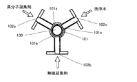
回転胴21内には、処理液の供給室26が設けられ、その周壁には、ボウル10と回転胴21との間の環状空間17に通ずる複数個の供給口27が開設されているとともに、ボウル10の中空軸40より挿通された処理液の供給管41が供給室26に開口して設けられている。二重構造になっている処理液供給管は、図1におけるZ−Z断面、X−X断面を図3、4に示すように、内管100が処理液通路となっており、その外側を囲む外管101は、高分子凝集剤供給路101a、無機凝集剤供給路101b、洗浄水供給路101cの3つに供給路に区画され、その上流端でそれぞれ供給口102a、102b、102cが設けられ、それぞれの供給配管を接続できるようになっている。
Next, a means and method for adding a flocculant in the above apparatus will be described.
A processing
高分子凝集剤供給路101aはそのまま内管100に沿って延びて、処理液供給室26で開口しており、処理液の周囲から供給室内に供給されて処理液と攪拌混合される。一方、無機凝集剤供給路101bは、処理液供給管41が処理液供給室26に達する上流側において、図5に示すように、開口して回転胴21に内周面に沿って画成された無機凝集剤の軸方向流路(図の実施形態では4本)105に通じる半径方向流路104に開口連通しており、後述するようにボウル内の遠心脱水される脱水ケーキの表面及び内部に無機凝集剤を添加するように構成されている。
The polymer
回転胴21の内部には、前述のように処理液供給室26が上流側よりに区画形成され、その下流側のストレート部の内部区間が無機凝集剤添加区域107となっており、テーパー部には無機凝集剤は達しないように構成されている。本発明では、無機凝集剤が効率的に処理液と混合し、かつ効果的に凝集効果を高めて脱水率の向上に寄与すると共に、高脱水率であっても脱水ケーキのボールからの排出を阻害することなく、良好な排出を可能にするために、次のような工夫を施した。
As described above, the processing
無機凝集剤は、処理液の水分が多い状態では効果が小さいので、本実施形態では処理液に遠心力の作用とスクリューコンベアの押圧力により脱水効果が生じ始める前記供給室より下流側からテーパー部に至るまでのストレート部の回転胴21の胴壁に、図6に示すように、前記無機凝集剤の軸方向流路105に通じる複数個のオリフィス108及び胴壁からボウル内に延びて突出するノズル109を設け、回転胴壁のオリフィス108から無機凝集剤を遠心場で脱水処理中の脱水ケーキ14の表面に後添加すると共に、ノズル109により脱水ケーキ14の内部に後添加することによって、無機凝集剤が脱水ケーキに均一に効果的に添加される。無機凝集剤の後添加位置は、処理液供給口27からケーキ排出側に向かってスクリューコンベアの螺旋翼22の1ピッチ〜2ピッチの区間が望ましいので、前記オリフィス及びノズルはストレート部のその区間に設けるのが望ましい。
Since the inorganic flocculant is less effective in the state where the moisture of the processing liquid is high, in this embodiment, the taper portion from the downstream side from the supply chamber where the dehydration effect starts to occur in the processing liquid due to the action of centrifugal force and the pressing force of the screw conveyor. As shown in FIG. 6, a plurality of
本発明者の実験によれば、無機凝集剤の添加はオリフィスによる回転胴の内周面から脱水ケーキ表面だけ、又はノズルにより内部への添加のみの場合と比べて、上記のようにオリフィスとノズルを組み合わせることにより添加効果が向上することがわかり、本実施形態では上記の位置にオリフィスとノズルを配置した。また、圧搾力が増大するテーパー部で凝集剤を添加すると、脱水ケーキが固まってしまいスクリューで押圧が困難でなるため、テーパー部では無機凝集剤を添加しないで、ストレート部のみで無機凝集剤を添加することとした。 According to the inventor's experiment, the addition of the inorganic flocculant is not limited to the case where only the addition from the inner peripheral surface of the rotary drum to the surface of the dewatered cake or the inside by the nozzle is performed. It can be seen that the addition effect is improved by combining these, and in this embodiment, the orifice and the nozzle are arranged at the above positions. In addition, if the flocculant is added at the taper part where the squeezing force increases, the dehydrated cake will be hardened and it will be difficult to press with a screw, so the inorganic flocculant is not added at the taper part, and the inorganic flocculant is added only at the straight part. It was decided to add.
上記の装置において、脱水処理する処理液は、処理液供給管41から処理液供給室26に入り、供給口27から環状空間17内に供給され、ボウル10及びスクリューコンベア20の回転の遠心力で固液分離されながら螺旋翼22により前端に向け搬送されるようになる。そして、分離された液体分である分離液は、後端壁の分離液排出口13から機外に排出される。一方、脱水ケーキは螺旋翼22によってボウル10の前端方向へと掻き寄せられて行きながら、さらに遠心力による分離作用を受けて、残留液分の分離が進み、その分離液は分離液排出口13より排出される。
In the above apparatus, the processing liquid to be dehydrated enters the processing
そして、本発明では、スクリューコンベア20の外周面は脱水ケーキ排出側に向けてテーパー構造となっているので、脱水ケーキは徐々に高遠心力場に移動され、且つ脱水ケーキ排出経路側に向かって脱水ケーキの通過面積が漸減するため、排出抵抗力及び体積減少力が増加し、脱水ケーキの含水率の更なる低下が可能となった。より詳細には、テーパー部の脱水ケーキの体積が徐々に減少するため圧搾効率が向上し、押し込み圧を有効に使用できる。その結果、負荷圧が軽減可能となり消費電力の低減が図れる。さらに、脱水分離液は、回転胴の脱水ケーキ排出側から分離液排出側に向かっての移動が容易となり、脱水ケーキへの分離液混入がなく低含水率の脱水ケーキのみの排出が可能となった。さらに、高脱水ケーキ保持容量が増え、上側溢流時の固形側への漏水防止効果が期待できる。さらに、また脱水ケーキ搬送力と液圧を押し込み圧として有効に利用できることから運転中の装置内閉塞が大幅に軽減される。
In the present invention, since the outer peripheral surface of the
以上のように、本実施形態の直胴型遠心脱水装置では、テーパー角度が30゜未満、10゜以上であり、脱水ケーキ供給口からストレート部の距離L1とテーパー部の距離L2の比L1/L2=1.2倍以上であると、従来の直胴型遠心脱水装置に比べて2%以上の含水率低下(即ち脱水率の向上)が得られ、さらに高分子凝集剤と機内のストレート部での無機凝集剤添加の二液添加法によって、2%以上の含水率低下が得られた。 As described above, in the straight body centrifugal dewatering device of this embodiment, the taper angle is less than 30 ° and 10 ° or more, and the ratio L1 / L1 between the distance L1 from the dewatered cake supply port to the straight portion and the distance L2 between the taper portions. When L2 = 1.2 times or more, the moisture content is reduced by 2% or more (that is, the dewatering rate is improved) compared to the conventional straight barrel centrifugal dewatering device, and the polymer flocculant and the straight portion in the machine With the two-component addition method of adding an inorganic flocculant, a water content reduction of 2% or more was obtained.
さらに、より脱水率を向上させるために、上記実施形態についてさらに研究した結果、上記実施形態のテーパー形状の場合、内半径側の高水分の脱水ケーキがテーパー部を移動して、ボウル底部の低含水率脱水ケーキと混合して排出されるためケーキ含水率の低下が困難な脱水ケーキ種が存在することがわかった。例えば、混合生汚泥の場合、固形分の脱水は限界値まで充分脱水できるが、テーパー面に達した分離液が固形分の表面に付着してその状態で排出されるため、結果的に脱水率の低下を阻害することになる。
すなわち、テーパー部先端に向けて高含水率脱水ケーキのショートパスが生じる。したがって、この高含水率脱水ケーキのショートパスを封じることによって、さらに脱水率を高めることが期待できる。ショートパスを防止する方法について、さらに研究した結果、以下に示すような方法が有効であることが確認された。
Furthermore, as a result of further research on the above-described embodiment in order to further improve the dehydration rate, in the case of the tapered shape of the above-described embodiment, the high-moisture dehydration cake on the inner radius side moves through the tapered portion, and the bottom of the bowl is reduced. It was found that there are some dehydrated cake species in which it is difficult to lower the moisture content of the cake because it is discharged after being mixed with the moisture content dehydrated cake. For example, in the case of mixed raw sludge, the dehydration of solids can be sufficiently dewatered to the limit value, but the separation liquid that reaches the tapered surface adheres to the surface of the solids and is discharged in that state, resulting in a dehydration rate as a result. Will be hindered.
That is, a short path of a high water content dehydrated cake is generated toward the tip of the tapered portion. Therefore, it is expected that the dehydration rate can be further increased by sealing the short path of the high water content dewatering cake. As a result of further research on the method of preventing the short pass, it was confirmed that the following method is effective.
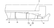
図7は、ショートパスの発生を防止した本発明の他の実施形態であり、以下の実施形態では、前記実施形態と同様な部分には同様な符号を付し、異なる要部のみについて説明する。
本実施形態では、回転胴21のテーパー部25を2段構造にしたことに特徴を有する。即ち、1段目は緩やかなテーパー部25a(傾斜角α1=5〜15゜)とし、2段目は1段目よりも急勾配なテーパー部25b(傾斜角α2=20〜60゜)としたものである。テーパー部25をこのように2段構造にすることによって、1段目の緩やかなテーパー部25aで脱水ケーキが圧搾される。そして、2段目の急勾配のテーパー部25bにより内半径の高含水率脱水ケーキは、ボウル底部のケーキ排出口に移動することなく緩やかなテーパー部25を分離液側に移動する。その結果、排出路から排出された機外脱水ケーキの含水率を、従来の直胴型と比較して約3〜4%低下させ得ることが確認できた。
FIG. 7 shows another embodiment of the present invention in which the occurrence of a short path is prevented. In the following embodiment, the same reference numerals are given to the same parts as those in the above embodiment, and only different main parts will be described. .
The present embodiment is characterized in that the tapered
図8は、ショートパスの発生を防止した本発明のさらに他の実施形態である。
本実施形態では、テーパー部25の入口(回転胴外周面の形状変換点)に高さ10mm程度のリング等で構成した堰29を設けることによってショートパスの発生を防止したものである。このようにテーパー部25の入口に段差を形成して堰29を設けることによって、高含水率脱水ケーキがテーパー部にショートパスすることを有効に防止することができた。なお、堰は本実施形態の場合に限らず、テーパー部の途中に形成することも可能である。
FIG. 8 shows still another embodiment of the present invention in which the occurrence of a short path is prevented.
In the present embodiment, the occurrence of a short path is prevented by providing a
図9は、ショートパスの発生を防止した本発明のさらに他の実施形態である。
本実施形態の遠心脱水装置では、回転胴21のテーパー部25の螺旋翼22のテーパー部表面と螺旋翼22の接続部に、図10に模式的に示すように一部に切り欠き30を設けることによって、螺旋翼22によって高含水率脱水ケーキがテーパー部25を押し上げて移動することを防止したものである。それにより、テーパー領域の内周側脱水ケーキを搬送させないようにし、高含水率脱水ケーキの排出側へのショートパスを有効に阻止することができる。
FIG. 9 shows still another embodiment of the present invention in which the occurrence of a short path is prevented.
In the centrifugal dehydrator of the present embodiment, a
以上の図7〜10に示す各実施形態は、有効に高含水率脱水ケーキのショートパスを防止することができるが、さらにこれらの手段を複合的に有することにより、より効果的にショートパスを防止することができる。
図11は、図7に示す実施形態に図8に示す実施形態のショートパス防止手段を付加したものであり、前記実施形態と同様な箇所に同一符号を付して詳細な説明は省略する。図12は、同様に図7に示す実施形態に図9に示す実施形態のショートパス防止手段を付加したものであり、前記実施形態と同様な箇所に同一符号を付して詳細な説明は省略する。
Each of the embodiments shown in FIGS. 7 to 10 can effectively prevent a short pass of a dehydrated cake with a high water content. However, by having these means combined, a short pass can be more effectively achieved. Can be prevented.
FIG. 11 is obtained by adding the short path preventing means of the embodiment shown in FIG. 8 to the embodiment shown in FIG. 7, and the same reference numerals are given to the same portions as in the above-described embodiment, and the detailed description is omitted. FIG. 12 is the same as the embodiment shown in FIG. 7 except that the short path prevention means of the embodiment shown in FIG. 9 is added. To do.
図1に示す実施形態の遠心脱水装置を使用して、無機凝集剤と高分子凝集剤の添加方法を変えた場合のケーキ含水率に及ぼす影響を調べた。なお、以下に示す実施例及び比較例とも回収率96〜98%の範囲内で行なった。
実施例1:
処理液:消化汚泥
無機凝集剤:ポリ硫酸第二鉄
高分子凝集剤:両性高分子凝集剤
添加方法:表1に示すように、高分子凝集剤を添加率0.92〜1.80DS%の間で変化させて処理液供給室に供給して処理液と攪拌混合させ、ポリ硫酸第二鉄を前記オリフィス及びノズルから常に一定量(添加量19.0L/h)添加して、そのときのケーキ含水率の変化を調べた。その結果、表1及び図13のグラフに示す線図aの結果が得られた。該結果から本実施例では、ケーキ含水率高分子凝集剤添加率0.92DS%で約73.4%で、1.55%で約71.6%、1.80%で71.1%というきわめて低い含水率になり、脱水効果が極めて高いことが確認された。
Using the centrifugal dehydrator of the embodiment shown in FIG. 1, the influence on the moisture content of the cake when the addition method of the inorganic flocculant and the polymer flocculant was changed was examined. In addition, it carried out within the range of 96-98% of the collection rate in the Example and comparative example which are shown below.
Example 1:
Treatment liquid: Digested sludge Inorganic flocculant: Polyferric sulfate Polymer flocculant: Amphoteric polymer flocculant Addition method: As shown in Table 1, the addition rate of polymer flocculant is 0.92-1.80 DS% It is changed between the two and supplied to the processing liquid supply chamber and stirred and mixed with the processing liquid, and a constant amount (addition amount 19.0 L / h) of polyferric sulfate is always added from the orifice and the nozzle. The change in the moisture content of the cake was examined. As a result, the result of the diagram a shown in Table 1 and the graph of FIG. 13 was obtained. From this result, in this example, the cake water content high polymer flocculant addition rate of 0.92 DS% is about 73.4%, 1.55% is about 71.6%, 1.80% is 71.1%. It was confirmed that the water content was extremely low and the dehydration effect was extremely high.
比較例1:
実施例1と同様な処理液に対して、実施例1おける高分子凝集剤のみを添加して、その添加率とケーキ含水率の変化を調べた。その結果を実施例1と共に図13に線図cとして示す。
比較例2
実施例と同様な処理液に対して、表1に示すように、同様な両性高分子凝集剤とポリ硫酸第二鉄とを従来の2液法と同様に、前添加(処理液に予め攪拌槽又は配管を通して、遠心脱水前の処理液に攪拌混合)して、無機凝集剤は実施例1と同様に一定量とし、高分子凝集剤の添加率実施例1と同様に変化させた。その結果、実施例1と共に表1および図13に線図bとして示す。
Comparative Example 1:
Only the polymer flocculant in Example 1 was added to the same treatment liquid as in Example 1, and changes in the addition rate and the moisture content of the cake were examined. The result is shown as a diagram c in FIG. 13 together with Example 1.
Comparative Example 2
As shown in Table 1, the same amphoteric polymer flocculant and polyferric sulfate were added in advance to the treatment solution similar to the examples as in the conventional two-component method (the treatment solution was previously stirred). The inorganic flocculant was fixed in the same amount as in Example 1 and the addition rate of the polymer flocculant was changed in the same manner as in Example 1. As a result, it is shown as a diagram b in Table 1 and FIG.

実施例1、比較例1、2の結果から明らかなように、実施例1の場合が高分子凝集剤の略同じ添加率に対して、ケーキ含水率が低下していることがわかる。しかも、無機凝集剤を前添加で行なう比較例2の場合は、無機凝集剤、高分子凝集剤とも実施例1と略同じ量添加しても実施例の方が、約2〜3%含水率を低下している結果が得られた。また、高分子凝集剤のみを添加する比較例1に比べれば、実施例は約6%以上も低下している結果が得られた。
以上の実施例から、本実施形態の装置および薬剤添加方法が従来技術と比較して格別な脱水効果があることが確認された。また、実施例及び比較例の何れの場合も脱水ケーキの排出不良を起こすことなく、高脱水率の場合も良好に排出することができ、本実施形態の遠心脱水装置が遠心脱水機能に優れていることが確認された。
As is clear from the results of Example 1 and Comparative Examples 1 and 2, it can be seen that the moisture content of the cake in Example 1 is lower than the substantially same addition rate of the polymer flocculant. Moreover, in the case of Comparative Example 2 in which the inorganic flocculant is added in advance, the water content of the example is about 2-3% even if both the inorganic flocculant and the polymer flocculant are added in substantially the same amount as in Example 1. The result of lowering was obtained. Moreover, compared with the comparative example 1 which adds only a polymer flocculent, the result in which the Example fell about 6% or more was obtained.
From the above examples, it was confirmed that the apparatus and the chemical addition method of the present embodiment have a special dehydration effect as compared with the prior art. Further, in any of the examples and comparative examples, the dewatered cake can be discharged without causing a poor discharge of the dehydrated cake, and the centrifugal dewatering device of the present embodiment has an excellent centrifugal dewatering function. It was confirmed that
次に、本発明の直胴型遠心装置の回転胴が径大方向にテーパー部を有することによる脱水ケーキの含水率低下を従来の直胴型遠心脱水装置と比較して確認するために実施例2及び比較例3に示す次のような実証試験を行った。
[実施例2および比較例3]
実施例2−1〜2−3として図1に示す実施形態の遠心脱水装置において、α=10゜、L1/L2=1.5/1(実施例2−1)、L1/L2=1.2/1(実施例2−2)、L1/L2=1/1(実施例2−3)である試験機をそれぞれ製作して、当該装置により処理液として混合生汚泥の脱水処理を高分子凝集剤の前添加のみで行い、それぞれについて機内脱水率分布状態を調べた。
また比較例3として従来の直胴型遠心脱水装置を使用して、同様な混合生汚泥の脱水処理の実証試験を同様に行って機内脱水率分布状態を調べた。
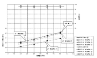
機内脱水率の分布状態の測定は、それぞれ遠心脱水装置の定常運転時に運転を非常停止させて完全停止後、装置を分解してスクリューコンベアの軸方向断面におけるスクリュー間に堆積している機内堆積ケーキを採取して、それぞれのスクリューピッチ毎の外周側・真中及び内周側の3点におけるケーキ含水率を測定することによって行った。その結果を図14に示す。
Next, in order to confirm the decrease in the moisture content of the dewatered cake due to the fact that the rotating drum of the straight cylinder type centrifugal device of the present invention has a taper portion in the large diameter direction, an example was confirmed in comparison with the conventional straight cylinder type centrifugal dehydrator. The following verification tests shown in 2 and Comparative Example 3 were performed.
[Example 2 and Comparative Example 3]
In the centrifugal dehydrator of the embodiment shown in FIG. 1 as Examples 2-1 to 2-3, α = 10 °, L1 / L2 = 1.5 / 1 (Example 2-1), L1 / L2 = 1. 2/1 (Example 2-2) and L1 / L2 = 1/1 (Example 2-3) were manufactured, respectively. The pre-addition of the flocculant was performed, and the in-flight dehydration rate distribution state was examined for each.
In addition, as a comparative example 3, a conventional straight barrel centrifugal dewatering device was used, and a similar verification test of the mixed raw sludge dewatering treatment was performed to examine the in-machine dewatering rate distribution state.
The distribution of the in-machine dewatering rate is measured by stopping the operation at the time of steady operation of the centrifugal dewatering equipment, completely stopping it, then disassembling the equipment and depositing it between the screws in the axial cross section of the screw conveyor. This was performed by measuring the moisture content of the cake at three points on the outer peripheral side, the middle, and the inner peripheral side for each screw pitch. The result is shown in FIG.
図14のグラフは、前記のように測定した実施例2−1〜2−3及び比較例3の機内脱水率の分布状態を示し、ピッチごとの3点の平均値を示している。その結果、従来の直胴型遠心脱水装置である比較例の場合は、図示のように機内含水率は排出側端部に向けてほぼ直線的に低下し、排出側端部の含水率は、略80.3%まで低下した。これに対し、実施例における機内含水率は、何れもテーパー起点に向けて比較例と比較して高い低下勾配で減少し、テーパー部で含水率の低下勾配はやや減少するが、含水率は排出部まで減少を続けている。実施例のうちL1/L2=1.5/1である実施例2−1が最も含水率の低下が見られ、78.0%まで低下し、従来の直胴型遠心脱水機に比べて約2%以上も含水率の低下が観測された。その理由は、回転胴の外周面下流側をテーパー形状にすることにより、排出抵抗力および体積減少力が増加することにより、ストレート部でテーパー起点に向けて含水率の低下率が比較例と比較して高い勾配で増大したと考えられる。したがって、回転胴の下流部をテーパー形状にすることにより、脱水ケーキの含水率の更なる低下が可能になることが確認された。また、実施例2におけるL1/L2の含水率への影響については、実施例2−1が実施例2−2、2−3よりも押し込み圧が充分確保でき、含水率低下により効果的であることが確認された。なお、図14のグラフにおいて「供給部」とは、図1に示す実施形態の直胴型遠心脱水装置において供給口27に相当する位置を示し、「排出部」とは脱水ケーキの排出経路の入口53に相当する位置を示している。
The graph of FIG. 14 shows the distribution state of the in-machine dewatering rates of Examples 2-1 to 2-3 and Comparative Example 3 measured as described above, and shows the average value of three points for each pitch. As a result, in the case of the comparative example which is a conventional straight barrel centrifugal dehydrator, the moisture content in the machine decreases almost linearly toward the discharge side end as shown in the figure, and the moisture content of the discharge side end is It decreased to about 80.3%. On the other hand, the moisture content in the machine in the examples all decreased toward the taper starting point with a high decline gradient compared to the comparative example, and the decline in moisture content at the taper portion slightly decreased, but the moisture content was discharged. Continues to decline. Of the examples, Example 2-1 where L1 / L2 = 1.5 / 1 shows the most decrease in water content, which is reduced to 78.0%, which is approximately compared with the conventional straight barrel centrifugal dehydrator. A decrease in water content was observed as much as 2% or more. The reason is that by making the downstream side of the outer peripheral surface of the rotating drum tapered, the discharge resistance force and the volume reduction force increase, and the rate of decrease in moisture content toward the taper starting point in the straight part is compared with the comparative example. It is thought that it increased with a high gradient. Therefore, it was confirmed that the water content of the dewatered cake can be further reduced by making the downstream portion of the rotating drum into a tapered shape. Moreover, about the influence on the moisture content of L1 / L2 in Example 2, Example 2-1 can fully ensure indentation pressure rather than Example 2-2, 2-3, and it is more effective by the moisture content fall. It was confirmed. In the graph of FIG. 14, the “supply section” indicates a position corresponding to the
[実施例3、比較例4]
実施例2−1で採用した遠心脱水装置において、実施例2の場合と同様に処理液として混合生汚泥の脱水処理を行った場合の遠心効果の影響を調べた。その結果を図15に示す。図15は、実施例3−1および比較例4の遠心効果を共に2000Gのもとで2m3/hの処理を回収率98%以上で行った場合の脱水ケーキの含水率と、実施例3−2では2500Gの遠心効果の基で2〜5m3/hを処理した場合の脱水ケーキ含水率と処理量との関係を示し、図16は、遠心効果と脱水ケーキ含水率との関係を示している。なお、図15、図16の各グラフには、そのときの回収率も併せて表示してある。また、図15には、後述する実施例5の結果も併せて表示してある。
実施例2−1の装置で混合生汚泥を処理量2m3/hを処理した場合の脱水ケーキの含水率は遠心効果2000Gで69.0%であった。これに対して、比較例3の装置で同じく混合生汚泥を処理量2m3/hを遠心効果2000Gで処理した場合の脱水ケーキの含水率71.8%であった(実施例3−1、比較例4)。
即ち、実施例3−1が比較例4よりも約2%含水率を低下させることができ、本発明の有効性が確認できた。そして、実施例3−2は、遠心効果2500Gで行った場合の処理量と脱水ケーキ含水率の関係を示しているが、処理量の増大により脱水ケーキ含水率は相関的に増大しており、この傾向は遠心効果2000Gの場合も見込まれるので、逆に実施例2−1の装置で比較例4の装置と同じ含水率71.8%の含水率で脱水処理をするとしたら、図15のグラフに示すように、実施例の装置では5m3/hの処理が可能となることを示し、実施例3−1では比較例4の2〜2.5倍の処理量が見込まれる。また、図16のグラフに示すように、同等含水率では1/2程度の遠心効果の低下が認められ、その分装置負荷の低減が可能となる。これらのことから、実施例は、比較例と比較して小型大容量化が可能であり、比較例と比較して大幅なコストの低減および省電力化が可能である。
[Example 3, Comparative Example 4]
In the centrifugal dehydration apparatus employed in Example 2-1, the influence of the centrifugal effect when the mixed raw sludge was dehydrated as the treatment liquid was examined in the same manner as in Example 2. The result is shown in FIG. FIG. 15 shows the water content of the dehydrated cake obtained when the centrifugal effect of Example 3-1 and Comparative Example 4 is both 2000 G and 2 m 3 / h treatment is performed at a recovery rate of 98% or more. -2 shows the relationship between the dehydrated cake moisture content and the treatment amount when 2-5 m 3 / h was treated based on the centrifugal effect of 2500 G, and FIG. 16 shows the relationship between the centrifugal effect and the moisture content of the dehydrated cake. ing. In addition, in each graph of FIG. 15, FIG. 16, the collection rate at that time is also displayed. FIG. 15 also shows the results of Example 5 described later.
The water content of the dehydrated cake in the case where the processing throughput of 2m 3 / h the mixture raw sludge in the apparatus of Example 2 -1 was 69.0% in the
That is, Example 3-1 was able to reduce the moisture content by about 2% compared to Comparative Example 4, and the effectiveness of the present invention was confirmed. And although Example 3-2 has shown the relationship between the processing amount at the time of performing with the centrifugal effect 2500G, and the water content of a dewatering cake, the water content of a dewatering cake is increasing correlatively by the increase in processing amount, Since this tendency is also expected in the case of the
[実施例4および比較例5]
実施例2−1と同様な装置(L1/L2=1.5/1)において、テーパー角度を10゜(実施例4−1)、30゜(実施例4−2)、40゜(実施例4−3)に変更した装置を試作して、処理液として嫌気性消化汚泥の脱水処理を行った。実証試験に供した処理液である嫌気性消化汚泥の脱水ケーキ濃度(TS)は1.82%、有機物濃度(VTS)は73.8%であった。実証試験は、遠心効果2500G、回収率99%以上の基で行い、処理量をそれぞれ2.0〜5.0m3/hに1.0m3/hづつ増やして4段階で行った。そのときの脱水ケーキの含水率は、それぞれ図17に示すとおりであった。
[Example 4 and Comparative Example 5]
In the same apparatus as in Example 2-1 (L1 / L2 = 1.5 / 1), the taper angle is 10 ° (Example 4-1), 30 ° (Example 4-2), 40 ° (Example) An apparatus changed to 4-3) was made as a trial, and anaerobic digested sludge was dehydrated as a treatment liquid. The dehydrated cake concentration (TS) of the anaerobic digested sludge, which is the treatment solution used for the verification test, was 1.82%, and the organic matter concentration (VTS) was 73.8%. Demonstration test was carried out by centrifugal effect 2500G, recovery rate of 99% or more of the groups were performed at 4 stages processing amount increases 1.0 m 3 / h increments to 2.0~5.0m 3 / h respectively. The water content of the dehydrated cake at that time was as shown in FIG.
図17から明らかなように、同一遠心効果のもとで処理量が増大することによって脱水ケーキの含水率は増大するが、処理量に関わらず実施例が比較例と比較してケーキ含水率の低下が認められた。特に、テーパー角度が10゜である実施例4−1の場合は、比較例と比較して2.0〜2.7%程度の低下が認められ、顕著な効果が認められた。なお、回転胴のテーパー角度は、実施例のうち小さい方が脱水ケーキ含水率低下傾向が認められる。以上のように、本発明に係る直胴型遠心脱水装置によれば、嫌気性消化汚泥でも混合生汚泥の場合と同様な効果が認められ、処理液の種類によらず脱水に効果的であることが確認された。 As is clear from FIG. 17, the moisture content of the dehydrated cake increases as the treatment amount increases under the same centrifugal effect. However, regardless of the treatment amount, the example has a higher moisture content than the comparative example. A decrease was observed. In particular, in the case of Example 4-1 having a taper angle of 10 °, a decrease of about 2.0 to 2.7% was recognized as compared with the comparative example, and a remarkable effect was recognized. In addition, the taper angle of a rotating drum has the tendency for a dehydration cake moisture content fall to the smaller one of an Example. As described above, according to the straight barrel centrifugal dewatering apparatus according to the present invention, the same effect as in the case of mixed raw sludge is recognized even in anaerobic digested sludge, and it is effective for dewatering regardless of the type of treatment liquid. It was confirmed.
[実施例5]
図7に示すように回転胴のテーパー部を2段テーパーにした場合の効果を確認するために、1段目のテーパー角度10゜、2段目のテーパー角度30゜の直胴型遠心脱水装置を製作し、該装置における遠心効果2500Gの基における処理量−脱水ケーキ含水率の関係を調べた。その結果、表2及び図15に示す結果が得られた。なお、処理液(汚泥種)は実施例3−1及び比較例4の場合と同様に、混合生汚泥である。
As shown in FIG. 7, in order to confirm the effect when the taper portion of the rotary cylinder is a two-stage taper, a straight cylinder type centrifugal dewatering apparatus having a first-stage taper angle of 10 ° and a second-stage taper angle of 30 °. Was manufactured, and the relationship between the amount of treatment and the water content of the dehydrated cake was examined based on the centrifugal effect 2500G in the apparatus. As a result, the results shown in Table 2 and FIG. 15 were obtained. The treatment liquid (sludge species) is mixed raw sludge as in Example 3-1 and Comparative Example 4.
本発明の直胴型遠心脱水装置は、下水処理や工業排水処理、化学・食品工業用諸生産品の脱水処理等に利用可能である。 The straight barrel type centrifugal dehydration apparatus of the present invention can be used for sewage treatment, industrial wastewater treatment, dehydration treatment of various products for chemical and food industries, and the like.
1 直胴型遠心脱水装置 10 ボウル
11 脱水ケーキ排出室壁 12 ボウル後端壁
13 分離液排出口 14 脱水ケーキ
15 周壁内面 17 環状空間
18 ボウル側絞り通路部材 19 ケーシング
20 スクリューコンベア 21 回転胴
22 螺旋翼 23 回転軸
24 ストレート部 25 テーパー部
26 供給室 27 供給口
28 逆テーパー面 29 堰
30 切り欠き 35 下流側の中空軸
401 上流側の中空軸 402 下流側の中空軸
41 処理液供給管 50 脱水ケーキ排出室
52 脱水ケーキ排出経路 53 入口
54 出口 60 分離液排出室
70 駆動装置 80 ベースフレーム
90、95 軸受部
100 内管 101 外管
101a 高分子凝集剤供給路 101b 無機凝集剤供給路
101c 洗浄水供給路 102a〜102c 供給口
104 半径方向流路 105 軸方向流路
108 オリフィス 109 ノズル
DESCRIPTION OF
Claims (9)
前記直胴型遠心脱水装置は、前記ボウルの内周壁が前記ボウルの回転軸に沿って延在する円筒形を形成し、且つ前記スクリューコンベアの前記回転胴の外周面が、上流側がストレートな円周面からなるストレート部と、下流側が前記ストレート部から径大方向に傾斜したテーパー部とから構成され、
前記回転胴の処理液供給口から前記テーパー部開始点までのストレート部の軸方向長さL1と、前記回転胴のテーパー部の軸方向長さL2との比L1/L2が1.2〜5.0の範囲であり、且つ前記テーパー部の開始部の傾斜角が5〜30゜の範囲内にあり、
前記処理液は、前記回転胴の内部に形成された処理液供給室を介して前記ボウルと前記スクリューコンベアとの間の環状空間に供給され、前記ボウル及び前記スクリューコンベアの回転の遠心力で固液分離されながら分離液は分離液排出口より排出され、脱水ケーキは遠心水頭圧と前記スクリューコンベアの搬送力とにより脱水ケーキ排出経路へ押出してなり、
前記脱水ケーキは、前記脱水ケーキ排出経路側に向けて前記テーパー部によって、徐々に高遠心力場に移動させ、かつ脱水ケーキ排出路側に向かって脱水ケーキの通過面積を漸減させて脱水することを特徴とする直胴型遠心脱水装置による遠心脱水方法。 A straight barrel bowl that rotates in one direction, and a screw conveyor in which spiral blades are wound around the outer periphery of the rotating drum that rotates in the same direction with a rotational speed difference coaxially with the bowl in the bowl In a centrifugal dehydration method using a straight barrel centrifugal dehydrator that performs solid-liquid separation of the treatment liquid by a straight barrel centrifugal dehydrator to collect solids and separated liquid,
The straight barrel type centrifugal dewatering device has a cylindrical shape in which the inner peripheral wall of the bowl extends along the rotation axis of the bowl, and the outer peripheral surface of the rotary drum of the screw conveyor is a circle whose upstream side is straight. A straight portion composed of a peripheral surface and a tapered portion whose downstream side is inclined in a large diameter direction from the straight portion,
A ratio L1 / L2 of the axial length L1 of the straight portion from the processing liquid supply port of the rotating drum to the tapered portion start point and the axial length L2 of the tapered portion of the rotating drum is 1.2 to 5 0.0 and the angle of inclination of the start of the tapered portion is in the range of 5-30 °,
The processing liquid is supplied to an annular space between the bowl and the screw conveyor via a processing liquid supply chamber formed inside the rotary drum, and is fixed by the centrifugal force of rotation of the bowl and the screw conveyor. While being separated, the separated liquid is discharged from the separated liquid discharge port, and the dehydrated cake is extruded into the dehydrated cake discharge path by the centrifugal head pressure and the conveying force of the screw conveyor,
The dehydrated cake is dehydrated by gradually moving to the high centrifugal force field toward the dehydrated cake discharge path side and gradually decreasing the passage area of the dehydrated cake toward the dehydrated cake discharge path side. A centrifugal dehydration method using a straight barrel centrifugal dehydrator.
前記ボウルの内周壁が前記ボウルの回転軸に沿って延在する円筒形を形成し、且つ前記スクリューコンベアの前記回転胴の外周面が、前記上流側がストレートな円周面からなるストレート部と、前記下流側が前記ストレート部から径大方向に傾斜したテーパー部とから構成され、前記テ―パー部のテーパー開始部の傾斜角が5乃至30゜の範囲内であり、
前記回転胴の処理液供給口から前記テーパー部開始点までのストレート部の軸方向長さL1と、前記回転胴のテーパー部の軸方向長さL2との比L1/L2が1.2〜5.0の範囲であることを特徴とする直胴型遠心脱水装置。 A straight barrel bowl that rotates in one direction, and a screw conveyor in which spiral blades are wound around the outer periphery of the rotating drum that rotates in the same direction with a rotational speed difference coaxially with the bowl in the bowl In a straight barrel centrifugal dehydrator,
A straight portion in which an inner peripheral wall of the bowl forms a cylindrical shape extending along a rotation axis of the bowl, and an outer peripheral surface of the rotary drum of the screw conveyor is formed of a circumferential surface having a straight upstream side; The downstream side is composed of a taper portion inclined in a large diameter direction from the straight portion, and the inclination angle of the taper start portion of the taper portion is in the range of 5 to 30 °,
A ratio L1 / L2 of the axial length L1 of the straight portion from the processing liquid supply port of the rotating drum to the tapered portion start point and the axial length L2 of the tapered portion of the rotating drum is 1.2 to 5 A straight barrel type centrifugal dewatering apparatus characterized by being in the range of 0.0 .
Priority Applications (8)
| Application Number | Priority Date | Filing Date | Title |
|---|---|---|---|
| JP2011232090A JP5191565B2 (en) | 2011-02-25 | 2011-10-21 | Centrifugal dehydration method and centrifugal dehydration apparatus |
| PCT/JP2012/053754 WO2012114985A1 (en) | 2011-02-25 | 2012-02-17 | Centrifugal dehydration method and centrifugal dehydration device |
| CN2012800100460A CN103415348A (en) | 2011-02-25 | 2012-02-17 | Centrifugal dehydration method and centrifugal dehydration device |
| US14/001,410 US9364837B2 (en) | 2011-02-25 | 2012-02-17 | Centrifugal dehydration method and centrifugal dehydration device |
| RU2013143296/05A RU2013143296A (en) | 2011-02-25 | 2012-02-17 | METHOD OF CENTRIFUGAL DEHYDRATION AND DEVICE FOR ITS IMPLEMENTATION |
| KR1020137025261A KR101557711B1 (en) | 2011-02-25 | 2012-02-17 | Centrifugal dehydration method and centrifugal dehydration device |
| EP12749994.5A EP2679312B1 (en) | 2011-02-25 | 2012-02-17 | Centrifugal dehydration method and centrifugal dehydration device |
| TW101105991A TWI542552B (en) | 2011-02-25 | 2012-02-23 | Centrifugal dewatering and centrifugal dewatering |
Applications Claiming Priority (3)
| Application Number | Priority Date | Filing Date | Title |
|---|---|---|---|
| JP2011039957 | 2011-02-25 | ||
| JP2011039957 | 2011-02-25 | ||
| JP2011232090A JP5191565B2 (en) | 2011-02-25 | 2011-10-21 | Centrifugal dehydration method and centrifugal dehydration apparatus |
Publications (3)
| Publication Number | Publication Date |
|---|---|
| JP2012187570A JP2012187570A (en) | 2012-10-04 |
| JP2012187570A5 JP2012187570A5 (en) | 2012-11-15 |
| JP5191565B2 true JP5191565B2 (en) | 2013-05-08 |
Family
ID=46720766
Family Applications (1)
| Application Number | Title | Priority Date | Filing Date |
|---|---|---|---|
| JP2011232090A Active JP5191565B2 (en) | 2011-02-25 | 2011-10-21 | Centrifugal dehydration method and centrifugal dehydration apparatus |
Country Status (8)
| Country | Link |
|---|---|
| US (1) | US9364837B2 (en) |
| EP (1) | EP2679312B1 (en) |
| JP (1) | JP5191565B2 (en) |
| KR (1) | KR101557711B1 (en) |
| CN (1) | CN103415348A (en) |
| RU (1) | RU2013143296A (en) |
| TW (1) | TWI542552B (en) |
| WO (1) | WO2012114985A1 (en) |
Families Citing this family (15)
| Publication number | Priority date | Publication date | Assignee | Title |
|---|---|---|---|---|
| JP2014200717A (en) * | 2013-04-02 | 2014-10-27 | 株式会社西原環境 | Solid-liquid separation apparatus and solid-liquid separation method |
| CN103657880B (en) * | 2013-12-18 | 2016-08-31 | 山东博润工业技术股份有限公司 | Split type screen sedimentation centrifuge spiral conveyor |
| JP6278307B2 (en) * | 2014-01-14 | 2018-02-14 | 三菱重工環境・化学エンジニアリング株式会社 | Centrifugal dehydrator |
| KR101602102B1 (en) * | 2015-04-27 | 2016-03-10 | 조돈균 | Centrifugal hydroextractor |
| JP6751564B2 (en) * | 2016-01-29 | 2020-09-09 | 株式会社クボタ | centrifuge |
| JP6498139B2 (en) * | 2016-03-09 | 2019-04-10 | 株式会社鶴見製作所 | Solid-liquid separation device and solid-liquid separation system |
| JP6420861B2 (en) * | 2017-03-23 | 2018-11-07 | 株式会社広島メタル&マシナリー | Centrifugal dehydrator |
| US10682585B2 (en) * | 2017-07-12 | 2020-06-16 | James William Masten, JR. | High-efficiency sludge dehydrator using an adaptive mechanical vapor re-compression process |
| CN108187928B (en) * | 2017-12-28 | 2021-04-09 | 攀枝花钢城集团有限公司 | Discharging device of industrial water and impurity separation equipment |
| CN108176521A (en) * | 2018-02-07 | 2018-06-19 | 广州市昊力工具有限公司 | Mud dehydration plant and the dry mud ship of dredging with mud dehydration plant |
| CN108514758B (en) * | 2018-06-11 | 2024-03-01 | 广东德诚化学技术有限公司 | Super-gravity water reducer dehydration equipment and water reducer dehydration method |
| CN109612206A (en) * | 2018-11-26 | 2019-04-12 | 上海恒霞环保设备有限公司 | A kind of efficient centrifugal dehumidifier |
| CN109678307A (en) * | 2019-02-21 | 2019-04-26 | 阮文渊 | A kind of Three-section type heating non-stick pan oily sludge pyrolysis installation |
| KR102504659B1 (en) * | 2019-11-18 | 2023-02-27 | 주식회사 엘지화학 | Pressurizing centrifugal dehydrator |
| CN111138065B (en) * | 2020-03-04 | 2022-07-05 | 重庆市三峡水务有限责任公司 | Sludge dewatering pretreatment device and pretreatment concentration method thereof |
Family Cites Families (20)
| Publication number | Priority date | Publication date | Assignee | Title |
|---|---|---|---|---|
| FR1029909A (en) * | 1950-12-19 | 1953-06-08 | Further development of continuous centrifugal dryers | |
| US2831575A (en) * | 1954-12-16 | 1958-04-22 | Raibl Societa Miniraria Del Pr | Centrifugal classifier for finely granulated solid substances in suspension |
| US3228594A (en) * | 1965-02-05 | 1966-01-11 | Clifford L Amero | Centrifugal separator |
| US3795361A (en) * | 1972-09-06 | 1974-03-05 | Pennwalt Corp | Centrifuge apparatus |
| JPS6023007Y2 (en) * | 1980-06-17 | 1985-07-09 | 株式会社クボタ | Horizontal centrifugal concentrator |
| JPH0641000B2 (en) | 1985-05-08 | 1994-06-01 | 石川島播磨重工業株式会社 | Sludge dewatering equipment |
| JPH0716630B2 (en) * | 1985-05-09 | 1995-03-01 | 石川島播磨重工業株式会社 | Screen-decanter centrifuge |
| JPH031077Y2 (en) * | 1985-07-12 | 1991-01-14 | ||
| JPS6238487A (en) | 1985-08-13 | 1987-02-19 | Fuji Xerox Co Ltd | Copying device |
| DE3622655A1 (en) * | 1986-07-05 | 1988-01-14 | Krauss Maffei Ag | Decanting centrifuge |
| US5261869A (en) | 1992-04-06 | 1993-11-16 | Alfa Laval Separation, Inc. | Decanter centrifuge having discontinuous flights in the beach area |
| GB9225067D0 (en) * | 1992-12-01 | 1993-01-20 | Broadbent & Sons Ltd Thomas | Decanting-type centrifuges |
| JP3402418B2 (en) * | 1995-08-21 | 2003-05-06 | 月島機械株式会社 | Centrifugal concentrator |
| JP3402419B2 (en) * | 1995-08-21 | 2003-05-06 | 月島機械株式会社 | Centrifugal concentrator |
| JP3615955B2 (en) * | 1999-02-19 | 2005-02-02 | 株式会社クボタ | Centrifugal dehydrator |
| JP3483791B2 (en) | 1999-03-08 | 2004-01-06 | 株式会社西原環境テクノロジー | Centrifuge with chemical injection means |
| JP4153138B2 (en) * | 2000-02-10 | 2008-09-17 | 株式会社クボタ | Centrifuge |
| JP2002153772A (en) * | 2000-11-22 | 2002-05-28 | Kubota Corp | Centrifuge |
| JP2006192403A (en) | 2005-01-17 | 2006-07-27 | Tokyo Electric Power Environmental Engineering Co Inc | Method for reducing water content in dewatered sludge |
| JP5490442B2 (en) | 2009-05-18 | 2014-05-14 | 株式会社西原環境 | Centrifuge |
-
2011
- 2011-10-21 JP JP2011232090A patent/JP5191565B2/en active Active
-
2012
- 2012-02-17 US US14/001,410 patent/US9364837B2/en not_active Expired - Fee Related
- 2012-02-17 WO PCT/JP2012/053754 patent/WO2012114985A1/en active Application Filing
- 2012-02-17 CN CN2012800100460A patent/CN103415348A/en active Pending
- 2012-02-17 RU RU2013143296/05A patent/RU2013143296A/en not_active Application Discontinuation
- 2012-02-17 KR KR1020137025261A patent/KR101557711B1/en active IP Right Grant
- 2012-02-17 EP EP12749994.5A patent/EP2679312B1/en not_active Not-in-force
- 2012-02-23 TW TW101105991A patent/TWI542552B/en active
Also Published As
| Publication number | Publication date |
|---|---|
| EP2679312A4 (en) | 2014-03-19 |
| EP2679312A1 (en) | 2014-01-01 |
| TW201245052A (en) | 2012-11-16 |
| KR101557711B1 (en) | 2015-10-06 |
| CN103415348A (en) | 2013-11-27 |
| JP2012187570A (en) | 2012-10-04 |
| KR20130122804A (en) | 2013-11-08 |
| US9364837B2 (en) | 2016-06-14 |
| WO2012114985A1 (en) | 2012-08-30 |
| TWI542552B (en) | 2016-07-21 |
| EP2679312B1 (en) | 2016-04-27 |
| RU2013143296A (en) | 2015-04-10 |
| US20130337991A1 (en) | 2013-12-19 |
Similar Documents
| Publication | Publication Date | Title |
|---|---|---|
| JP5191565B2 (en) | Centrifugal dehydration method and centrifugal dehydration apparatus | |
| JP6619247B2 (en) | centrifuge | |
| KR100935819B1 (en) | Horizontal type port screw decanter centrifugal | |
| KR100916032B1 (en) | Centrifugal hydroextractor for Submerged Sludge of Animal Waste Water | |
| CN202823653U (en) | Screw feeder and horizontal screw centrifuge applying screw feeder | |
| JP6420861B2 (en) | Centrifugal dehydrator | |
| KR100953671B1 (en) | The separating screw decanter centrifuges having helical designed outlet for discharging concentrated liquid or cake | |
| CN102824966B (en) | Screw material pusher and horizontal screw centrifuge using same | |
| JP6814865B2 (en) | centrifuge | |
| JP6751564B2 (en) | centrifuge | |
| JP2013107022A (en) | Filter medium type centrifugal dehydrator | |
| JP2008043914A (en) | Sludge thickening apparatus | |
| CN112295745A (en) | Horizontal screw machine feed arrangement structure | |
| JP2003245574A (en) | Decanter type centrifugal dewatering apparatus and centrifugal dewatering method using the same | |
| FI65766B (en) | CENTRIFUG MED TVAO CONCENTRATE TRUMMOR FOR AVVATTNING AV SLAM | |
| CN211339242U (en) | Oil-water-solid three-phase separation high-speed horizontal spiral sedimentation centrifuge | |
| CN109499788B (en) | Drum special for sludge dewatering centrifugal machine | |
| CN217796711U (en) | High-dry type large-throughput spiral pusher | |
| CN216005601U (en) | High-efficient type environmental protection centrifugal dehydrator for engineering | |
| CN214416700U (en) | Horizontal screw machine feed arrangement structure | |
| KR101070684B1 (en) | Decanter | |
| JPH01189358A (en) | Sludge dehydration method and apparatus using decanter type centrifugal separator | |
| JP2022155606A (en) | Centrifugal dehydrator and method for dehydrating slurry containing organic solid particles | |
| CN219615809U (en) | Double-cone type three-phase separation horizontal spiral centrifugal machine | |
| KR100762401B1 (en) | Centrifugal sedimentation control device |
Legal Events
| Date | Code | Title | Description |
|---|---|---|---|
| A521 | Request for written amendment filed |
Free format text: JAPANESE INTERMEDIATE CODE: A523 Effective date: 20120830 |
|
| A621 | Written request for application examination |
Free format text: JAPANESE INTERMEDIATE CODE: A621 Effective date: 20120830 |
|
| A871 | Explanation of circumstances concerning accelerated examination |
Free format text: JAPANESE INTERMEDIATE CODE: A871 Effective date: 20120830 |
|
| A975 | Report on accelerated examination |
Free format text: JAPANESE INTERMEDIATE CODE: A971005 Effective date: 20121001 |
|
| A131 | Notification of reasons for refusal |
Free format text: JAPANESE INTERMEDIATE CODE: A131 Effective date: 20121010 |
|
| A521 | Request for written amendment filed |
Free format text: JAPANESE INTERMEDIATE CODE: A523 Effective date: 20121210 |
|
| TRDD | Decision of grant or rejection written | ||
| A01 | Written decision to grant a patent or to grant a registration (utility model) |
Free format text: JAPANESE INTERMEDIATE CODE: A01 Effective date: 20130116 |
|
| A61 | First payment of annual fees (during grant procedure) |
Free format text: JAPANESE INTERMEDIATE CODE: A61 Effective date: 20130129 |
|
| R150 | Certificate of patent or registration of utility model |
Ref document number: 5191565 Country of ref document: JP Free format text: JAPANESE INTERMEDIATE CODE: R150 Free format text: JAPANESE INTERMEDIATE CODE: R150 |
|
| FPAY | Renewal fee payment (event date is renewal date of database) |
Free format text: PAYMENT UNTIL: 20160208 Year of fee payment: 3 |
|
| R250 | Receipt of annual fees |
Free format text: JAPANESE INTERMEDIATE CODE: R250 |
|
| S533 | Written request for registration of change of name |
Free format text: JAPANESE INTERMEDIATE CODE: R313533 |
|
| R350 | Written notification of registration of transfer |
Free format text: JAPANESE INTERMEDIATE CODE: R350 |
|
| R250 | Receipt of annual fees |
Free format text: JAPANESE INTERMEDIATE CODE: R250 |
|
| R250 | Receipt of annual fees |
Free format text: JAPANESE INTERMEDIATE CODE: R250 |
|
| R250 | Receipt of annual fees |
Free format text: JAPANESE INTERMEDIATE CODE: R250 |
|
| R250 | Receipt of annual fees |
Free format text: JAPANESE INTERMEDIATE CODE: R250 |
|
| R250 | Receipt of annual fees |
Free format text: JAPANESE INTERMEDIATE CODE: R250 |
|
| R250 | Receipt of annual fees |
Free format text: JAPANESE INTERMEDIATE CODE: R250 |
|
| R250 | Receipt of annual fees |
Free format text: JAPANESE INTERMEDIATE CODE: R250 |
|
| R250 | Receipt of annual fees |
Free format text: JAPANESE INTERMEDIATE CODE: R250 |