JP5171663B2 - Electric booster - Google Patents

Electric booster Download PDF

Info

Publication number
JP5171663B2
JP5171663B2 JP2009014180A JP2009014180A JP5171663B2 JP 5171663 B2 JP5171663 B2 JP 5171663B2 JP 2009014180 A JP2009014180 A JP 2009014180A JP 2009014180 A JP2009014180 A JP 2009014180A JP 5171663 B2 JP5171663 B2 JP 5171663B2
Authority
JP
Japan
Prior art keywords
linear motion
housing
piston
input rod
seal ring
Prior art date
Legal status (The legal status is an assumption and is not a legal conclusion. Google has not performed a legal analysis and makes no representation as to the accuracy of the status listed.)
Expired - Fee Related
Application number
JP2009014180A
Other languages
Japanese (ja)
Other versions
JP2010167987A5 (en
JP2010167987A (en
Inventor
哲夫 木村
正義 江口
卓也 小畑
孝幸 大野
行雄 大谷
Current Assignee (The listed assignees may be inaccurate. Google has not performed a legal analysis and makes no representation or warranty as to the accuracy of the list.)
Nissan Motor Co Ltd
Hitachi Astemo Ltd
Original Assignee
Nissan Motor Co Ltd
Hitachi Automotive Systems Ltd
Priority date (The priority date is an assumption and is not a legal conclusion. Google has not performed a legal analysis and makes no representation as to the accuracy of the date listed.)
Filing date
Publication date
Application filed by Nissan Motor Co Ltd, Hitachi Automotive Systems Ltd filed Critical Nissan Motor Co Ltd
Priority to JP2009014180A priority Critical patent/JP5171663B2/en
Publication of JP2010167987A publication Critical patent/JP2010167987A/en
Publication of JP2010167987A5 publication Critical patent/JP2010167987A5/ja
Application granted granted Critical
Publication of JP5171663B2 publication Critical patent/JP5171663B2/en
Expired - Fee Related legal-status Critical Current
Anticipated expiration legal-status Critical

Links

Images

Landscapes

  • Braking Systems And Boosters (AREA)

Description

本発明は、電動モータにより駆動される倍力装置の技術分野に関する。   The present invention relates to the technical field of a booster driven by an electric motor.

従来、電動モータにより駆動される倍力装置として特許文献1に記載の技術が開示されている。この特許文献1に記載の電動倍力装置では、ハウジングの後端側にボールねじの直動部材に当接すると共にインプットロッドに係止されるダストブーツが設けられている。   Conventionally, the technique of patent document 1 is disclosed as a booster driven by an electric motor. In the electric booster described in Patent Document 1, a dust boot is provided on the rear end side of the housing so as to abut against the linear motion member of the ball screw and be engaged with the input rod.

特開2008−296782号公報JP 2008-296782 A

しかしながら、上記従来技術のダストブーツでは、インプットロッドと直動部材とが相対変位する際、ダストブーツのインプットロッドの係止がずれてしまう可能性があり、ハウジング内にゴミ等が進入してボールねじの効率や寿命が低下する虞がある。   However, in the above conventional dust boot, when the input rod and the linear motion member are relatively displaced, there is a possibility that the locking of the input rod of the dust boot may be shifted, and dust or the like enters the housing and enters the ball. The efficiency and life of the screw may be reduced.

本発明は、上記問題に着目してなされたもので、入力部材とブースタピストンとの相対変位に係らずハウジング内の気密性を向上した電動倍力装置を提供することにある。   The present invention has been made paying attention to the above problem, and provides an electric booster that improves the airtightness in the housing irrespective of the relative displacement between the input member and the booster piston.

上記目的を達成するため、本発明では、電動倍力装置において、ハウジング内の気密を保つ第1のシールリングをハウジングと回転直動変換機構の直動部材の後端側外周との間に設け、ハウジング内の気密を保つ第2のシールリングを回転直動変換機構の直動部材とブースタピストンの後端側外周との間、または、前記回転直動変換機構の直動部材の前端側内周と前記ハウジングとの間に設けた。 In order to achieve the above object, according to the present invention, in the electric booster, the first seal ring that keeps the airtightness in the housing is provided between the housing and the outer periphery of the rear end side of the linear motion member of the rotation / linear motion conversion mechanism. The second seal ring that keeps hermeticity in the housing is provided between the linear motion member of the rotation / linear motion conversion mechanism and the rear end side outer periphery of the booster piston , or in the front end side of the linear motion member of the rotation / linear motion conversion mechanism It was provided between the circumference and the housing .

よって、入力部材とブースタピストンとが相対変位してもシール材に過負荷が作用することなくハウジング内の気密性を保つことができる。   Therefore, even if the input member and the booster piston are relatively displaced, the airtightness in the housing can be maintained without overload acting on the sealing material.

実施例1の電動倍力装置を表す断面図である。1 is a cross-sectional view illustrating an electric booster according to a first embodiment. 実施例1のインプットロッド周辺を表す部分拡大断面図である。FIG. 3 is a partial enlarged cross-sectional view illustrating the periphery of the input rod according to the first embodiment. 実施例2のインプットロッド周辺を表す部分拡大断面図である。FIG. 6 is a partial enlarged cross-sectional view illustrating the periphery of an input rod according to a second embodiment. 参考技術1のインプットロッド周辺を表す部分拡大断面図である。 It is a partial expanded sectional view showing the input rod circumference of reference technology 1 . 参考技術2のインプットロッド周辺を表す部分拡大断面図である。 It is a partial expanded sectional view showing the input rod circumference of reference technology 2 . 参考技術3のインプットロッド周辺を表す部分拡大断面図である。 It is a partial expanded sectional view showing the input rod circumference of reference technology 3 .

以下、本発明の実施形態について図面に基づいて説明する。   Hereinafter, embodiments of the present invention will be described with reference to the drawings.

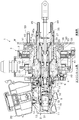
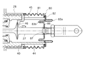
図1は実施例1の電動倍力装置の構成を表す断面図、図2は実施例1のインプットロッド周辺を表す部分拡大断面図である。尚、各断面図においてケース部28の部分だけは、インプットロッド27の軸心から上半分と下半分とが直交する断面を取ったものである。電動倍力装置1は、タンデム型マスタシリンダに組込まれるものであって、略有底円筒状のマスタシリンダ本体2(マスタシリンダ)の開口端に結合されるハウジング3を備えている。ハウジング3は、マスタシリンダ側及び図外のブレーキペダル側に開口部を有する略円筒状のハウジング本体4と、マスタシリンダ本体2の開口端に連結される略円筒状の案内部材5と、案内部材5をハウジング本体4の底部の開口部に取付けるフロントカバー6と、ハウジング本体4内に後述する電動モータ38等を収装した状態でブレーキペダル側の開口部を閉塞するリヤカバー7とで構成されている。マスタシリンダ本体2は、ハウジング3の案内部材5と結合して1つのシリンダボアを形成し、このシリンダボアには、直列に配置された略有底円筒状のプライマリピストン8(ブースタピストン)及びセカンダリピストン9が摺動可能に嵌装され、これらの間にプライマリ圧力室10が形成され、セカンダリピストン9とマスタシリンダ本体2の底部との間にセカンダリ圧力室11が形成されている。マスタシリンダ本体2の側壁には、プライマリ圧力室10に連通するプライマリポート12及びセカンダリ圧力室11に連通するセカンダリポート13が設けられており、プライマリ及びセカンダリポート12,13には、それぞれ各車輪に設けられたブレーキ装置を作動させるホイールシリンダ(図示せず)が接続される。   FIG. 1 is a cross-sectional view illustrating the configuration of the electric booster according to the first embodiment. FIG. 2 is a partially enlarged cross-sectional view illustrating the periphery of the input rod according to the first embodiment. In each cross-sectional view, only the case portion 28 has a cross section in which the upper half and the lower half are orthogonal to each other from the axis of the input rod 27. The electric booster 1 is incorporated in a tandem master cylinder and includes a housing 3 coupled to an open end of a substantially bottomed cylindrical master cylinder body 2 (master cylinder). The housing 3 includes a substantially cylindrical housing body 4 having openings on the master cylinder side and a brake pedal side (not shown), a substantially cylindrical guide member 5 connected to the opening end of the master cylinder body 2, and a guide member. And a rear cover 7 that closes the opening on the brake pedal side in a state where an electric motor 38 or the like to be described later is housed in the housing body 4. Yes. The master cylinder body 2 is combined with the guide member 5 of the housing 3 to form one cylinder bore. The cylinder bore has a substantially bottomed cylindrical primary piston 8 (booster piston) and secondary piston 9 arranged in series. Are slidably fitted, a primary pressure chamber 10 is formed between them, and a secondary pressure chamber 11 is formed between the secondary piston 9 and the bottom of the master cylinder body 2. A primary port 12 that communicates with the primary pressure chamber 10 and a secondary port 13 that communicates with the secondary pressure chamber 11 are provided on the side wall of the master cylinder main body 2. A wheel cylinder (not shown) for operating the brake device provided is connected.

マスタシリンダ本体2のシリンダボアとプライマリピストン8との間は、軸方向に間隔をもって配置された一対のピストンシール14及びシール15によってシールされ、これらのピストンシール14とシール15との間にプライマリリリーフポート16が開口されている。同様に、マスタシリンダ本体2のシリンダボアとセカンダリピストン9との間は、軸方向に間隔をもって配置された一対のピストンシール17及びシール18によってシールされ、これらの間にセカンダリリリーフポート19が開口されている。プライマリ及びセカンダリリリーフポート16,19には,ブレーキ液を貯留するリザーバ20が接続されている。そして、プライマリピストン8が原位置(非制動位置)にあるとき、その側壁に設けられたピストンポート21及びプライマリリリーフポート16によってプライマリ圧力室10がリザーバ20に接続され、プライマリピストン8が前進すると、その側壁によってプライマリリリーフポート16とピストンポート21との間がピストンシール14によって遮断されてプライマリ圧力室10が加圧される。同様に、セカンダリピストン9が原位置(非制動位置)にあるとき、その側壁に設けられたピストンポート22及びセカンダリリリーフポート19によってセカンダリ圧力室11がリザーバ20に接続され、セカンダリピストン9が前進すると、その側壁によってセカンダリリリーフポート19とピストンポート22との間がピストンシール17によって遮断されてセカンダリ圧力室11が加圧される。   A space between the cylinder bore of the master cylinder body 2 and the primary piston 8 is sealed by a pair of piston seals 14 and 15 that are spaced apart in the axial direction, and a primary relief port is provided between the piston seal 14 and the seal 15. 16 is opened. Similarly, the cylinder bore of the master cylinder main body 2 and the secondary piston 9 are sealed by a pair of piston seals 17 and 18 that are arranged at intervals in the axial direction, and a secondary relief port 19 is opened between them. Yes. A reservoir 20 for storing brake fluid is connected to the primary and secondary relief ports 16 and 19. When the primary piston 8 is in the original position (non-braking position), the primary pressure chamber 10 is connected to the reservoir 20 by the piston port 21 and the primary relief port 16 provided on the side wall thereof, and when the primary piston 8 moves forward, The side wall blocks the primary relief port 16 and the piston port 21 by the piston seal 14 and pressurizes the primary pressure chamber 10. Similarly, when the secondary piston 9 is in the original position (non-braking position), the secondary pressure chamber 11 is connected to the reservoir 20 by the piston port 22 and the secondary relief port 19 provided on the side wall thereof, and the secondary piston 9 moves forward. The secondary relief port 19 and the piston port 22 are blocked by the piston seal 17 by the side wall, and the secondary pressure chamber 11 is pressurized.

案内部材5には、シール15との間に軸方向に間隔をもって設けられてプライマリピストン8との間をシールするシール部材23が設けられている。そして、ピストンシール15とシール部材23との間の空間Sは、マスタシリンダ本体2と案内部材5との間に形成された排出通路24を介してフロントカバー6の前方の外部に開放されている。プライマリピストン8の底部及びプライマリピストン8の内部に嵌合されたガイド部材25には、入力ピストン26が摺動可能かつ液密的に挿入されている。入力ピストン26は、プライマリ圧力室10に対する受圧面積がプライマリピストン8に対して充分小さくなるように充分小径となっている。プライマリピストン8から突出された入力ピストン26の後端部には、インプットロッド27の先端部が連結されており、インプットロッド27の基端側は、リヤカバー7に形成された円筒状のケース部28に挿通されて外部へ延出され、その基端部にはブレーキペダル(図示せず)が連結されるようになっている。   The guide member 5 is provided with a seal member 23 that is provided between the seal 15 and the primary piston 8 so as to be spaced apart in the axial direction. A space S between the piston seal 15 and the seal member 23 is opened to the outside in front of the front cover 6 via a discharge passage 24 formed between the master cylinder main body 2 and the guide member 5. . An input piston 26 is slidably and liquid-tightly inserted into the guide member 25 fitted into the bottom of the primary piston 8 and the inside of the primary piston 8. The input piston 26 has a sufficiently small diameter so that the pressure receiving area with respect to the primary pressure chamber 10 is sufficiently smaller than that of the primary piston 8. A distal end portion of an input rod 27 is connected to a rear end portion of the input piston 26 protruding from the primary piston 8, and a base end side of the input rod 27 is a cylindrical case portion 28 formed on the rear cover 7. And a brake pedal (not shown) is connected to the base end portion of the base pedal.

プライマリピストン8の後端部は、円筒状の延長部材29が連結されてリヤカバー7のケース部28の内部まで延ばされている。延長部材29の後端部には、外側フランジ30が形成されている。セカンダリピストン9は、マスタシリンダ本体2の底部との間に設けられた戻しばね31によって付勢され、プライマリピストン8は、セカンダリピストン9との間に設けられた戻しバネ32及び案内部材5の後端部と延長部材29の外側フランジ部30との間に設けられた戻しバネ33によって原位置へ付勢されている。また、入力ピストン26は、プライマリピストン8の底部との間に設けられたバネ34及び延長部材29のバネ受35との間に設けられたバネ36によってプライマリピストン8に対して軸方向に弾性的に保持されている。   A cylindrical extension member 29 is connected to the rear end portion of the primary piston 8 and extends to the inside of the case portion 28 of the rear cover 7. An outer flange 30 is formed at the rear end of the extension member 29. The secondary piston 9 is urged by a return spring 31 provided between the secondary piston 9 and the bottom of the master cylinder body 2, and the primary piston 8 is disposed behind the return spring 32 and the guide member 5 provided between the secondary piston 9. It is biased to the original position by a return spring 33 provided between the end portion and the outer flange portion 30 of the extension member 29. Further, the input piston 26 is elastic in the axial direction with respect to the primary piston 8 by a spring 34 provided between the bottom portion of the primary piston 8 and a spring receiver 35 of the extension member 29. Is held in.

ハウジング3内には、回転直動変換機構であるボール−ネジ機構37と、電動モータ38と、レゾルバ39とが設けられている。ボール−ネジ機構37は、リヤカバー7のケース部28内に挿入されて軸方向に移動可能に案内され、内部にプライマリピストン8の後部及び延長部材29が挿入された円筒状の直動部材40と、直動部材40に外嵌された円筒状の回転部材41と、これらの間に形成された螺旋状のボール溝40a,41aに装填された複数のボール43とを備えている。ボール溝40a,41a及びボール43には潤滑剤としてグリスが塗布されている。   In the housing 3, a ball-screw mechanism 37 that is a rotation / linear motion conversion mechanism, an electric motor 38, and a resolver 39 are provided. The ball-screw mechanism 37 is inserted into the case portion 28 of the rear cover 7 and is guided so as to be movable in the axial direction, and a cylindrical linear motion member 40 in which the rear portion of the primary piston 8 and the extension member 29 are inserted. A cylindrical rotating member 41 fitted on the linear motion member 40 and a plurality of balls 43 loaded in spiral ball grooves 40a and 41a formed therebetween are provided. The ball grooves 40a and 41a and the ball 43 are coated with grease as a lubricant.

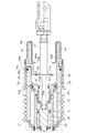
図2に示すように、直動部材40は、後端部がリヤカバー7のケース部28から外部に延出されており、延出部44に形成されたスリット45に、ケース部28の端部に形成された爪部46が嵌合することにより、軸方向の移動を可能にすると共にその回転を規制している。この回転規制は直動部材40のストローク位置がどの位置であっても行われる必要があるため、延出部44の延出量は直動部材40の最大ストローク量よりも長く設定されている。また、延出部44の外周はケース部28内周により案内(支持)され、これにより直動部材40の安定したストロークを実現する。直動部材40の内周部には、プライマリピストン8に連結された延長部材29の外側フランジ部30に当接する内側フランジ部47が形成されている。インプットロッド27の途中には円錐状に拡径されたストッパ部27aが形成されている。そして、ケース部28内周に形成された爪部46は、ストッパ部27aと係合してインプットロッド27の後退位置を規定している。ケース部28の車室内側には金属製のカバー部材48がカシメ固定されている。このカバー部材48は延出部44を取り囲むように二重筒形状とされており、内筒の底面に形成された開口48aにインプットロッド27が貫通している。   As shown in FIG. 2, the linear motion member 40 has a rear end portion extending outward from the case portion 28 of the rear cover 7, and an end portion of the case portion 28 is formed in a slit 45 formed in the extension portion 44. When the claw portions 46 formed in are fitted, the movement in the axial direction is made possible and the rotation thereof is restricted. Since this rotation regulation needs to be performed regardless of the stroke position of the linear motion member 40, the extension amount of the extension portion 44 is set longer than the maximum stroke amount of the linear motion member 40. Further, the outer periphery of the extending portion 44 is guided (supported) by the inner periphery of the case portion 28, thereby realizing a stable stroke of the linear motion member 40. An inner flange portion 47 that abuts on the outer flange portion 30 of the extension member 29 connected to the primary piston 8 is formed on the inner peripheral portion of the linear motion member 40. In the middle of the input rod 27, a stopper portion 27a having a conical diameter is formed. The claw portion 46 formed on the inner periphery of the case portion 28 engages with the stopper portion 27a to define the retracted position of the input rod 27. A metal cover member 48 is caulked and fixed to the vehicle interior side of the case portion 28. The cover member 48 is formed in a double cylinder shape so as to surround the extending portion 44, and the input rod 27 passes through an opening 48a formed in the bottom surface of the inner cylinder.

電動モータ38は、ハウジング3に固定されたステータ49と、ハウジング3に軸受50,51によって回転可能に支持されたロータ52とを備え、ロータ52は、ボール−ネジ機構37の回転部材41に連結されている。そして、ステータ49のコイル53への通電によってロータ52を回転させ、回転直動変換機構であるボール−ネジ機構37の回転部材41を回転させることにより、ボール43がボール溝40a,41a内を転動して直動部材40が軸方向に沿って直線運動する。このとき、レゾレバ39によって電動モータ38の回転変位(位置)を検出する。直動部材40が前進すると、直動部材40の内側フランジ47が延長部材29の外側フランジ30を押圧してプライマリピストン8を前進させる。   The electric motor 38 includes a stator 49 fixed to the housing 3 and a rotor 52 rotatably supported on the housing 3 by bearings 50 and 51, and the rotor 52 is connected to the rotating member 41 of the ball-screw mechanism 37. Has been. Then, the rotor 52 is rotated by energizing the coil 53 of the stator 49, and the rotating member 41 of the ball-screw mechanism 37, which is a rotation / linear motion conversion mechanism, is rotated, whereby the ball 43 rotates in the ball grooves 40a and 41a. The linear motion member 40 moves and linearly moves along the axial direction. At this time, the rotational displacement (position) of the electric motor 38 is detected by the reso lever 39. When the linear motion member 40 advances, the inner flange 47 of the linear motion member 40 presses the outer flange 30 of the extension member 29 to advance the primary piston 8.

電動倍力装置1は、ハウジング3のリヤカバー7に立設されたスタットボルト59によって、車両のエンジンルームと車室との隔壁であるダッシュパネルWのエンジンルーム側に取付けられ、リヤカバー7のケース部28がダッシュパネルWに挿通されて車室側へ延ばされ、インプットロッド27にブレーキペダル(図示せず)が連結される。そして、インプットロッド27の変位を検出する変位センサ、プライマリ及びセカンダリ圧力室10,11の圧力を検出する圧力センサ等の各種センサ(図示せず)、並びに、これらのセンサ及びレゾルバ39の検出に基づいて電動モータ38の回転を制御するコントローラ(図示せず)が設けられる。   The electric booster 1 is attached to the engine room side of the dash panel W which is a partition wall between the engine room and the vehicle compartment of the vehicle by a stat bolt 59 erected on the rear cover 7 of the housing 3. 28 is inserted through the dash panel W and extended toward the passenger compartment, and a brake pedal (not shown) is connected to the input rod 27. And based on the detection of the various sensors (not shown), such as a displacement sensor which detects the displacement of the input rod 27, the pressure sensor which detects the pressure of the primary and secondary pressure chambers 10 and 11, and these sensors and the resolver 39. A controller (not shown) for controlling the rotation of the electric motor 38 is provided.

(シールリングの構成)
次に、直動部材40とケース部28との間及び直動部材40と延長部材29との間のシールについて図2を用いて説明する。直動部材40の外周であってボール溝40aの延出部44側の端部には、ハウジング3内の気密を保つための第1シールリング60が設けられている。第1シールリング60は、直動部材40の外周に形成されたシール溝40b内に装着された弾性部材60aと、弾性部材60aの外周側に装着された樹脂等からなる摺動部材60bとから構成されている。弾性部材60aは、摺動部材60bに対して外周方向に適度な押し付け力を付与できるゴム材料から形成されている。また、摺動部材60bは摺動性を考慮した例えばPTFE(ポリテトラフルオロエチレン:フッ化炭素樹脂)から形成されている。これにより、ケース部28に対する直動部材40の移動を円滑にするとともに、開口48aから延出部44を迂回してボール−ネジ機構37内に進入してくる埃やゴミを遮断して、ハウジング3内の気密を保つようにしている。
(Structure of seal ring)
Next, seals between the linear motion member 40 and the case portion 28 and between the linear motion member 40 and the extension member 29 will be described with reference to FIG. A first seal ring 60 for maintaining airtightness in the housing 3 is provided on the outer periphery of the linear motion member 40 and on the end of the ball groove 40a on the extending portion 44 side. The first seal ring 60 includes an elastic member 60a mounted in a seal groove 40b formed on the outer periphery of the linear motion member 40, and a sliding member 60b made of resin or the like mounted on the outer peripheral side of the elastic member 60a. It is configured. The elastic member 60a is formed of a rubber material that can give an appropriate pressing force to the sliding member 60b in the outer circumferential direction. The sliding member 60b is made of, for example, PTFE (polytetrafluoroethylene: fluorocarbon resin) considering slidability. Accordingly, the linear motion member 40 can be moved smoothly with respect to the case portion 28, and dust and dust entering the ball-screw mechanism 37 by bypassing the extension portion 44 from the opening 48a can be blocked. 3 is kept airtight.

延長部材29の外周には、ハウジング3内の気密を保つための第2シールリング70が設けられている。第2シールリング70は、延長部材29の外周に形成されたシール溝29a内に装着された弾性部材70aと、弾性部材70aの外周側に装着された摺動部材70bとから構成されている。この弾性部材70及び摺動部材70bは、第1シールリング60と基本的に同じ素材から構成されているため説明を省略する。これにより、直動部材40に対する延長部材29の移動を円滑にするとともに、開口48aから進入してくる埃やゴミを遮断し、直動部材40の内周を迂回して外周側のボール−ネジ機構37内に埃やゴミが進入することを遮断して、ハウジング3内の気密を保つようにしている。尚、第1シールリング60及び第2シールリング70は、摺動耐久性と防塵性が確保可能であれば、二つの部材から構成する必要は無く、例えばゴム材料からなる弾性部材のみで構成してもよい。   A second seal ring 70 is provided on the outer periphery of the extension member 29 to keep the inside of the housing 3 airtight. The second seal ring 70 includes an elastic member 70a mounted in a seal groove 29a formed on the outer periphery of the extension member 29, and a sliding member 70b mounted on the outer peripheral side of the elastic member 70a. Since the elastic member 70 and the sliding member 70b are basically made of the same material as the first seal ring 60, the description thereof is omitted. This facilitates the movement of the extension member 29 relative to the linear motion member 40, blocks dust and dirt entering from the opening 48a, bypasses the inner periphery of the linear motion member 40, and has a ball-screw on the outer peripheral side. Dust and dust are prevented from entering the mechanism 37 to keep the housing 3 airtight. The first seal ring 60 and the second seal ring 70 need not be composed of two members as long as sliding durability and dust resistance can be ensured. For example, the first seal ring 60 and the second seal ring 70 are composed only of an elastic member made of a rubber material. May be.

(電動倍力装置の作用)
システム正常時において、ブレーキペダル(インプットロッド27)の操作によって入力ピストン26を前進させると、コントローラからの制御電流によって電動モータ38が回転し、ボール−ネジ機構37を介してプライマリピストン8を前進させて入力ピストン26に追従させ、プライマリ及びセカンダリ圧力室10,11を加圧する。これにより、ブレーキペダルの操作に応じて電動モータ38によってサーボ力を付与して倍力制御を行う。このとき、プライマリ圧力室10の圧力が入力ピストン26(受圧面積小)を介してインプットロッド27(ブレーキペダル)にフィードバックされる。また、各種センサの検出に基づいて、コントローラによって電動モータ38の回転を適宜制御することにより、ブレーキアシスト制御、回生協調制御、車両追従制御等のブレーキ制御を実行する。このとき、入力ピストン26の移動に応じて直動部材40がストロークするため、第1シールリング60は、ケース部28内周に対して相対移動することになる。一方、入力ピストン26とプライマリピストン8とは、上記ブレーキ制御時の所定の倍力比を発生させるために相対変位する。これにより、圧力室10,11に入力ピストン26の受圧面積とプライマリピストン8の受圧面積比に応じた倍力比、もしくは入力ピストン26とプライマリピストン8の相対変位量に応じた倍力比に倍力された圧力を発生させるようになっている。
(Operation of electric booster)
When the input piston 26 is advanced by operating the brake pedal (input rod 27) when the system is normal, the electric motor 38 is rotated by the control current from the controller, and the primary piston 8 is advanced via the ball-screw mechanism 37. Thus, the primary and secondary pressure chambers 10 and 11 are pressurized by following the input piston 26. Thus, servo control is applied by the electric motor 38 according to the operation of the brake pedal, and the boost control is performed. At this time, the pressure in the primary pressure chamber 10 is fed back to the input rod 27 (brake pedal) via the input piston 26 (small pressure receiving area). Further, based on the detection of various sensors, the controller appropriately controls the rotation of the electric motor 38, thereby executing brake control such as brake assist control, regenerative cooperative control, and vehicle follow-up control. At this time, since the linear motion member 40 strokes according to the movement of the input piston 26, the first seal ring 60 moves relative to the inner periphery of the case portion 28. On the other hand, the input piston 26 and the primary piston 8 are relatively displaced in order to generate a predetermined boost ratio during the brake control. Thus, the pressure chambers 10 and 11 are doubled to a boost ratio corresponding to the pressure receiving area ratio of the input piston 26 and the primary piston 8 or to a boost ratio corresponding to the relative displacement amount of the input piston 26 and the primary piston 8. It is designed to generate a forced pressure.

一方、システムフェールによって電動モータ38が駆動できない場合には、直動部材40のストロークも停止する。このとき、運転者がブレーキペダル(インプットロッド27)を操作すると、入力ピストン26のみがストロークして、入力ピストン26に伝達された推力が、ばね34、引いては入力ピストン26の段部を介してプライマリピストン8に伝達されて移動し、プライマリピストン8と連結された延長部材29もストロークする。よって、直動部材40の内側フランジ部47と延長部材29とが離間してこれらが相対移動することになる。これにより、圧力室10,11に最低限のブレーキ力が確保できる程度の圧力を発生させる。このとき、第2シールリング70は、直動部材40内周に対して相対移動することになる。尚、上記場合、電動モータ38による倍力作用が得られないことは言うまでもない。   On the other hand, when the electric motor 38 cannot be driven due to the system failure, the stroke of the linear motion member 40 is also stopped. At this time, when the driver operates the brake pedal (input rod 27), only the input piston 26 strokes, and the thrust transmitted to the input piston 26 passes through the spring 34 and then through the step of the input piston 26. The extension member 29 connected to the primary piston 8 is also stroked. Therefore, the inner flange portion 47 of the linear motion member 40 and the extension member 29 are separated from each other and are relatively moved. As a result, pressure is generated in the pressure chambers 10 and 11 such that a minimum braking force can be secured. At this time, the second seal ring 70 moves relative to the inner periphery of the linear motion member 40. In the above case, it goes without saying that the boosting action by the electric motor 38 cannot be obtained.

上述のように、ハウジング内の気密を保つ第1シールリング60をハウジングのケース部28内周と回転直動変換機構であるボール−ネジ機構37の直動部材40の後端側外周との間に設け、ハウジング内の気密を保つ第2シールリング70を直動部材40とプライマリピストン8の後端側に取り付けられた延長部材29の外周との間に設けた。すなわち、第1シールリング60及び第2シールリング70は、軸方向に相対変位する部材の間で摺動するため、インプットロッド27と直動部材40とが相対変位したとしても、ハウジング内の気密性を確保することができる。言い換えると、特許文献1に記載のような蛇腹のブーツで覆うことなくボール−ネジ機構37への埃やゴミの進入を回避できる。また、システム正常時及びシステムフェール時のいずれであってもシール部分が軸方向に引っ張られるような負荷が生じないため、シール部材の耐久性の向上を図ることができる。   As described above, the first seal ring 60 that keeps hermeticity in the housing is between the inner periphery of the case portion 28 of the housing and the outer periphery of the rear end side of the linear member 40 of the ball-screw mechanism 37 that is a rotation / linear motion conversion mechanism. The second seal ring 70 is provided between the linear motion member 40 and the outer periphery of the extension member 29 attached to the rear end side of the primary piston 8. That is, since the first seal ring 60 and the second seal ring 70 slide between the members that are relatively displaced in the axial direction, even if the input rod 27 and the linear motion member 40 are relatively displaced, the airtightness in the housing Sex can be secured. In other words, entry of dust and dirt into the ball-screw mechanism 37 can be avoided without covering with a bellows boot as described in Patent Document 1. In addition, since the load that causes the seal portion to be pulled in the axial direction does not occur even when the system is normal or the system fails, the durability of the seal member can be improved.

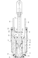
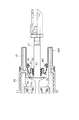
次に実施例2について説明する。基本的な構成は実施例1と同じであるため異なる点についてのみ説明する。図3は実施例2のインプットロッド周辺を表す部分拡大断面図である。実施例1では、第2シールリング70を直動部材40内周と延長部材29外周との間に設けた。これに対し、実施例2では、案内部材5の後端側を、初期位置において直動部材40の前端と径方向に重なる位置まで延長し、直動部材40内周と案内部材5の外周との間に第2シールリング70を備えた点が異なる。また、実施例1では、第1シールリング60及び第2シールリング70をそれぞれ弾性部材と摺動部材とから形成されたシール部材としたが、実施例2では断面丸型のゴム部材いわゆるOリングを使用している点で異なる。   Next, Example 2 will be described. Since the basic configuration is the same as that of the first embodiment, only different points will be described. FIG. 3 is a partially enlarged cross-sectional view showing the periphery of the input rod according to the second embodiment. In the first embodiment, the second seal ring 70 is provided between the inner periphery of the linear motion member 40 and the outer periphery of the extension member 29. On the other hand, in the second embodiment, the rear end side of the guide member 5 is extended to a position overlapping the front end of the linear motion member 40 in the radial direction at the initial position, and the inner periphery of the linear motion member 40 and the outer periphery of the guide member 5 are The second seal ring 70 is provided between the two. In the first embodiment, each of the first seal ring 60 and the second seal ring 70 is a seal member formed of an elastic member and a sliding member. However, in the second embodiment, a so-called O-ring having a round cross section is used. It is different in using.

非作動時において、延長部材29は内側フランジ部47と当接している。ここで、システムフェールのときには直動部材40は停止することから延長部材29と直動部材40とは相対移動し、ブレーキペダルを急踏みしたときに直動部材40の応答が遅れたときにも、延長部材29と直動部材40とは相対移動する。すなわち、延長部材29と内側フランジ部47とは状態に応じて当接と離間の状態を取る。特に離間したとき、この隙間から埃やゴミが進入してきたとしても、第2シールリング70によりボール−ネジ機構37側への侵入を回避できる。案内部材5は固定部材であり、直動部材40が最も後端に位置する初期状態において径方向に重なっているため、直動部材40がどのようにストロークしたとしても、第2シールリング70は直動部材40との間でシール機能を発揮する。一般に、円筒部材の内周側に摺動面を形成すると、内周面の面粗度を確保するための加工が困難である。これに対し、実施例2では、案内部材5の外周が摺動面となるため、面粗度を確保する際に加工が容易である。   When not in operation, the extension member 29 is in contact with the inner flange portion 47. Here, since the linear motion member 40 stops during a system failure, the extension member 29 and the linear motion member 40 move relative to each other, and the response of the linear motion member 40 is delayed when the brake pedal is suddenly depressed. The extension member 29 and the linear motion member 40 move relative to each other. That is, the extension member 29 and the inner flange portion 47 are brought into contact with and separated from each other depending on the state. In particular, even when dust or dirt enters from this gap when separated, the second seal ring 70 can prevent the ball-screw mechanism 37 from entering. The guide member 5 is a fixed member, and since the linear motion member 40 overlaps in the radial direction in the initial state where the linear motion member 40 is located at the rearmost end, the second seal ring 70 does not matter how the linear motion member 40 is stroked. A sealing function is exhibited with the linear motion member 40. In general, when a sliding surface is formed on the inner peripheral side of a cylindrical member, it is difficult to process to ensure the surface roughness of the inner peripheral surface. On the other hand, in Example 2, since the outer periphery of the guide member 5 is a sliding surface, processing is easy when ensuring surface roughness.

上述のように、ハウジング内の気密を保つ第1シールリング60をハウジングのケース部28内周とボール−ネジ機構37(回転直動変換機構)の直動部材40の後端側外周との間に設け、ハウジング3内の気密を保つ第2シールリング70を直動部材40の前端側内周とハウジングである案内部材5の外周との間に設けた。よって、実施例1と同様の作用効果を得ることができる。   As described above, the first seal ring 60 that keeps hermeticity in the housing is between the inner periphery of the case portion 28 of the housing and the outer periphery of the linear motion member 40 of the ball-screw mechanism 37 (rotational linear motion conversion mechanism). The second seal ring 70 is provided between the front end side inner periphery of the linear motion member 40 and the outer periphery of the guide member 5 as a housing. Therefore, the same effect as Example 1 can be obtained.

(参考技術1)
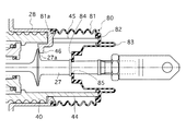
次に参考技術1について説明する。基本的な構成は実施例1と同じであるため異なる点についてのみ説明する。図4は参考技術1のインプットロッド周辺を表す部分拡大断面図である。実施例1では、第1シールリング60をハウジング3のケース部28内周とボール−ネジ機構37の直動部材40の後端側外周との間に設け、第2シールリング70を直動部材40内周と延長部材29外周との間に設けた。これに対し、参考技術1では、シールリングではなく、ケース部28とインプットロッド27との間を覆うブーツ部材80を設けた点で異なる。ブーツ部材80は、ハウジングであるケース部28の開口に固定される一端部81aと、この一端部81aと延出部44後端との間を外側から取り囲む蛇腹部81と、延出部44後端に対して固定する固定部82(中間固定部)と、固定部82から後端側に一端延在された後に折り返された折り返し部83(多重折曲部)と、折り返し部83と接続すると共に内側フランジ46に対するストッパとして機能するストッパ部84と、ストッパ部84の底面に形成されインプットロッド27に対して相対移動しないように挿通固定されるための内径シール部85(他端部)と、を有する多重筒状とされている。
(Reference technology 1)
Next, Reference Technique 1 will be described. Since the basic configuration is the same as that of the first embodiment, only different points will be described. FIG. 4 is a partially enlarged cross-sectional view showing the periphery of the input rod of Reference Technique 1 . In the first embodiment, the first seal ring 60 is provided between the inner periphery of the case portion 28 of the housing 3 and the outer periphery of the linear motion member 40 of the ball-screw mechanism 37, and the second seal ring 70 is provided as the linear motion member. 40 between the inner periphery of 40 and the outer periphery of the extension member 29. On the other hand, the reference technique 1 is different in that a boot member 80 that covers the space between the case portion 28 and the input rod 27 is provided instead of the seal ring. The boot member 80 includes an end portion 81a fixed to the opening of the case portion 28 that is a housing, a bellows portion 81 that surrounds the space between the one end portion 81a and the extended portion 44 from the outside, and a rear portion of the extended portion 44. A fixed portion 82 (intermediate fixed portion) that is fixed to the end, a folded portion 83 (multiple folded portion) that is folded back after extending from the fixed portion 82 to the rear end side, and the folded portion 83 are connected. A stopper portion 84 that functions as a stopper for the inner flange 46, and an inner diameter seal portion 85 (the other end portion) that is formed on the bottom surface of the stopper portion 84 and is inserted and fixed so as not to move relative to the input rod 27; It is made into the multiple cylinder shape which has.

直動部材40がストロークすると、それに従って蛇腹部81が適宜変形して追従するため、蛇腹部81や固定部82に過剰な負荷が作用することはない。また、インプットロッド27は軸方向にストロークすることに加えて、インプットロッド27には、ブレーキペダルの回転運動を直動運動に変換するために生じる幾何学的な傾きによって力が斜め方向に作用する場合があり、これによりインプットロッド27が揺動する。このような揺動に対しては折り返し部83が適宜変形して追従するため、固定部82等に過剰な負荷が作用することはない。また、直動部材40とインプットロッド27とが相対移動した場合には、ストッパ部84が内側フランジ部46と当接するまでの間は折り返し部83の折り返し位置が変形して追従するため、固定部82等に過剰な負荷が作用することはない。ストッパ部84が内側フランジ部46と当接すると、それ以降は、内径シール部85とインプットロッド27とが相対移動する。このとき、ストッパ部84はそれ以上移動しないから固定部82等に過剰な負荷が作用することはない。   When the linear motion member 40 strokes, the bellows portion 81 is appropriately deformed and follows the stroke accordingly, so that no excessive load is applied to the bellows portion 81 and the fixed portion 82. Further, in addition to the stroke of the input rod 27 in the axial direction, a force acts on the input rod 27 in an oblique direction due to a geometric inclination generated to convert the rotational movement of the brake pedal into the linear motion. In some cases, the input rod 27 swings. Since the folding portion 83 is appropriately deformed and follows such swinging, an excessive load does not act on the fixed portion 82 and the like. Further, when the linear motion member 40 and the input rod 27 are relatively moved, the folding position of the folding portion 83 is deformed and follows until the stopper portion 84 comes into contact with the inner flange portion 46. An excessive load does not act on 82 etc. When the stopper portion 84 comes into contact with the inner flange portion 46, the inner diameter seal portion 85 and the input rod 27 are relatively moved thereafter. At this time, since the stopper portion 84 does not move any more, an excessive load does not act on the fixed portion 82 and the like.

以上説明したように、ハウジングであるケース部28の開口とインプットロッド27との間には可撓性材からなる多重筒状のブーツ部材80が設けられ、ブーツ部材80は、ケース部28の開口に固定される一端部81aと、インプットロッド27に摺動可能に固定される内径シール部85(他端部)と、一端部81aと内径シール部85との間に設けられ延出部44後端(ブースタピストンの一端)に固定される固定部82(中間固定部)と、固定部82と一端部81aとの間に形成されハウジングに対する直動部材40(ブースタピストン)の移動を吸収する蛇腹部81と、固定部82と内径シール部85との間に形成され直動部材40(ブースタピストン)とインプットロッド27との相対移動を吸収する折り返し部83(多重折曲部)と、を有する。よって、インプットロッド27と直動部材40とが相対変位しても、また、インプットロッド27が直動部材40に対して揺動しても、ハウジング内の気密性を保つことができる。   As described above, the multi-cylindrical boot member 80 made of a flexible material is provided between the opening of the case portion 28 that is a housing and the input rod 27, and the boot member 80 corresponds to the opening of the case portion 28. One end portion 81a fixed to the input rod 27, an inner diameter seal portion 85 (other end portion) fixed to the input rod 27 so as to be slidable, and an extension portion 44 provided between the one end portion 81a and the inner diameter seal portion 85. A bellows which is formed between a fixing portion 82 (intermediate fixing portion) fixed to the end (one end of the booster piston) and the fixing portion 82 and one end portion 81a and absorbs the movement of the linear motion member 40 (booster booster piston) relative to the housing. Portion 81, a folded portion 83 (multiple bent portion) that is formed between fixed portion 82 and inner diameter seal portion 85 and absorbs relative movement between linear motion member 40 (booster piston) and input rod 27. And, with a. Therefore, even if the input rod 27 and the linear motion member 40 are relatively displaced, and the input rod 27 swings with respect to the linear motion member 40, the airtightness in the housing can be maintained.

(参考技術2)
次に参考技術2について説明する。基本的な構成は参考技術1と同じであるため異なる点についてのみ説明する。図5は参考技術2のインプットロッド27周辺を表す部分拡大断面図である。参考技術1では、ストッパ部84と内径シール部85を設け、インプットロッド27とブーツ部材80とが相対移動可能に構成した。これに対し、参考技術2では、インプットロッド27とブーツ部材80とを固定し、相対移動を禁止しつつ、折り返し部を追加した点で異なる。ブーツ部材80は、ハウジングであるケース部28の開口に固定される一端部81aと、この一端部81aと延出部44後端との間を外側から取り囲む蛇腹部81と、延出部44後端に対して固定する固定部82(中間固定部)と、固定部82から後端側に一端延在された後に折り返された第1折り返し部83a(多重折曲部)と、第1折り返し部83aから固定部82よりもケース部28内径側まで延在された後に再度折り返された第2折り返し部83b(多重折曲部)と、第2折り返し部83bと接続する係合部86と、係合部86の底面に形成されインプットロッド27に対して相対移動しないように挿通固定されるための固定穴87(他端部)と、を有する多重筒状とされている。
(Reference technology 2)
Next, Reference Technique 2 will be described. Since the basic configuration is the same as that of the reference technique 1 , only different points will be described. FIG. 5 is a partially enlarged cross-sectional view showing the periphery of the input rod 27 of Reference Technique 2 . In the reference technique 1 , the stopper portion 84 and the inner diameter seal portion 85 are provided, and the input rod 27 and the boot member 80 are configured to be relatively movable. On the other hand, the reference technique 2 is different in that the input rod 27 and the boot member 80 are fixed and a relative portion is prohibited and a turn-back portion is added. The boot member 80 includes an end portion 81a fixed to the opening of the case portion 28 that is a housing, a bellows portion 81 that surrounds the space between the one end portion 81a and the extended portion 44 from the outside, and a rear portion of the extended portion 44. A fixing portion 82 (intermediate fixing portion) that is fixed to the end, a first folding portion 83a (multiple folding portion) that is folded back after extending from the fixing portion 82 to the rear end side, and a first folding portion A second folded portion 83b (multiple folded portion) which is folded from 83a to the inner diameter side of the case portion 28 with respect to the fixed portion 82 and then folded back; an engaging portion 86 connected to the second folded portion 83b; It is formed in a multiple cylinder shape having a fixing hole 87 (other end portion) formed on the bottom surface of the joint portion 86 and inserted and fixed so as not to move relative to the input rod 27.

直動部材40がストロークすると、それに従って蛇腹部81が適宜変形して追従するため、蛇腹部81や固定部82に過剰な負荷が作用することはない。また、インプットロッド27は軸方向にストロークすることに加えて、ブレーキペダルの回転運動を直動運動に変換するために生じる幾何学的な傾きによって力が斜め方向に作用する場合があり、これによりインプットロッド27が揺動する。このような揺動に対しては第1及び第2折り返し部83a,bが適宜変形して追従するため、固定部82等に過剰な負荷が作用することはない。また、直動部材40とインプットロッド27とが相対移動した場合には、終始、第1及び第2折り返し部83a,bの折り返し位置が変形して追従するため、固定部82や固定穴87等に過剰な負荷が作用することはない。よって、参考技術1と同様の作用効果を得ることができる。 When the linear motion member 40 strokes, the bellows portion 81 is appropriately deformed and follows the stroke accordingly, so that an excessive load does not act on the bellows portion 81 and the fixing portion 82. Further, in addition to the stroke in the axial direction, the input rod 27 may act in an oblique direction due to a geometric inclination generated to convert the rotational motion of the brake pedal into a linear motion. The input rod 27 swings. Since the first and second folded portions 83a and 83b are appropriately deformed to follow such a swing, an excessive load does not act on the fixed portion 82 and the like. Further, when the linear motion member 40 and the input rod 27 are relatively moved, the folding positions of the first and second folding parts 83a, 83b are deformed and follow from beginning to end, so that the fixing part 82, the fixing hole 87, etc. Excessive load will not be applied. Therefore, it is possible to obtain the same effects as those of the reference technique 1 .

(参考技術3)
次に参考技術3について説明する。基本的な構成は実施例1と同じであるため異なる点についてのみ説明する。図6は参考技術3のインプットロッド周辺を表す部分拡大断面図である。実施例1では、ケース部28内周と直動部材40外周との間に第1シールリング60を設け、直動部材40内周と延長部材29外周との間に第2シールリング70を設けた。これに対し、参考技術3では、シールリングではなく、ケース部28とインプットロッド27との間を覆う第2カバー部材90を設けた点で異なる。ケース部28の車室内側には金属製の第1カバー部材480がカシメ固定されている。この第1カバー部材480は延出部44を取り囲むように二重筒形状とされており、内筒の底面に形成された開口には後述する第2カバー部材90を係止する係止溝481が折り曲げ形成されている。第2カバー部材90は、可撓性部材であるゴム製の係止溝481と係合する肉厚部94と、肉厚部94から軸方向に延在された後に折り返されたゴム製の第1折り返し部91と、第1折り返し部91から軸方向に延在された後に再度折り返されたゴム製の第2折り返し部92と、第2折り返し部92により折り返された円筒部内周に固定され、インプットロッド27と摺動接触するPTFE製の筒状部材93とを有する。尚、PTFEとはポリテトラフルオロエチレン(フッ化炭素樹脂)を表すものであるが、摺動性が確保されるのであれば、摺動性のよいゴム部材を用いてもよいし、他の材料から形成してもよい。
(Reference technology 3)
Next, Reference Technique 3 will be described. Since the basic configuration is the same as that of the first embodiment, only different points will be described. FIG. 6 is a partially enlarged cross-sectional view showing the periphery of the input rod of Reference Technique 3 . In the first embodiment, the first seal ring 60 is provided between the inner periphery of the case portion 28 and the outer periphery of the linear motion member 40, and the second seal ring 70 is provided between the inner periphery of the linear motion member 40 and the outer periphery of the extension member 29. It was. On the other hand, the reference technique 3 is different in that a second cover member 90 that covers the space between the case portion 28 and the input rod 27 is provided instead of the seal ring. A metal first cover member 480 is caulked and fixed to the vehicle interior side of the case portion 28. The first cover member 480 is formed in a double cylinder shape so as to surround the extending portion 44, and a locking groove 481 for locking a second cover member 90 described later in an opening formed in the bottom surface of the inner cylinder. Is bent. The second cover member 90 includes a thick portion 94 that engages with a rubber locking groove 481 that is a flexible member, and a second rubber member that is folded back after extending from the thick portion 94 in the axial direction. 1 folded portion 91, a second folded portion 92 made of rubber that has been axially extended from the first folded portion 91 and then folded again, and an inner periphery of the cylindrical portion folded by the second folded portion 92, A PTFE tubular member 93 that is in sliding contact with the input rod 27 is provided. PTFE represents polytetrafluoroethylene (fluorocarbon resin), but a rubber member with good slidability may be used as long as slidability is ensured, or other materials. You may form from.

第1カバー部材480及び第2カバー部材90は共にハウジングに固定された部材であるため、インプットロッド27がストロークすると、直動部材40との相対移動等に係らず筒状部93内周とインプットロッド27が相対移動する。このとき、筒状部93は摺動性が確保されているため、第1カバー部材480や第2カバー部材90に過剰な負荷が作用することはない。また、インプットロッド27が径方向に揺動したとしても、第1折り返し部91及び第2折り返し部92が適宜変形して追従するため、筒状部93等に過剰な負荷が作用することはない。   Since both the first cover member 480 and the second cover member 90 are members fixed to the housing, when the input rod 27 strokes, the inner periphery of the cylindrical portion 93 and the input are not affected by the relative movement with the linear motion member 40 or the like. The rod 27 moves relatively. At this time, since the slidability of the cylindrical portion 93 is ensured, an excessive load does not act on the first cover member 480 and the second cover member 90. Even if the input rod 27 swings in the radial direction, the first folded portion 91 and the second folded portion 92 are appropriately deformed and follow up, so that an excessive load does not act on the tubular portion 93 or the like. .

以上説明したように、ハウジングであるケース部28の開口に外周端が固定され該外周端から延出部44の外周に沿って延びて延出部44の突出端で内周側に折り返されて延びる二重筒状の第1カバー部材480と、第1カバー部材480の内周端に一端が固定され、他端がインプットロッド27に対して摺動可能にシールする可撓性材からなる筒状の第2カバー部材90とを有する。よって、インプットロッド27と直動部材40とが相対変位してもハウジング内の気密性を保つことができる。   As described above, the outer peripheral end is fixed to the opening of the case portion 28 that is a housing, extends from the outer peripheral end along the outer periphery of the extending portion 44, and is folded back to the inner peripheral side at the protruding end of the extending portion 44. A first tube member 480 extending in a double cylinder shape, and a tube made of a flexible material having one end fixed to the inner peripheral end of the first cover member 480 and the other end slidably sealed with respect to the input rod 27. And a second cover member 90 having a shape. Therefore, even if the input rod 27 and the linear motion member 40 are relatively displaced, the airtightness in the housing can be maintained.

1 電動倍力装置
2 マスタシリンダ本体
4 ハウジング本体
7 リヤカバー
8 プライマリピストン(ブースタピストン)
26 入力ピストン
27 インプットロッド(入力部材)
28 ケース部(ハウジング)
29 延長部材(ブースタピストン)
37 ボール−ネジ機構(回転直動変換機構)
38 電動モータ
40 直動部材(ブースタピストン)
44 延出部(ブースタピストン)
60 第1シールリング
70 第2シールリング
80 ブーツ部材
90 第2カバー部材
480 第1カバー部材
1 Electric Booster 2 Master Cylinder Body 4 Housing Body 7 Rear Cover 8 Primary Piston (Booster Piston)
26 Input piston 27 Input rod (input member)
28 Case (housing)
29 Extension member (Booster piston)
37 Ball-screw mechanism (rotation linear motion conversion mechanism)
38 Electric motor 40 Linear member (Booster piston)
44 Extension part (Booster piston)
60 First seal ring 70 Second seal ring 80 Boot member 90 Second cover member 480 First cover member

Claims (1)

筒状に形成されたハウジングと、
該ハウジングの開口から一端が突出して設けられて前記ハウジングに対して移動することでマスタシリンダの圧力室を加圧する筒状のブースタピストンと、
該ブースタピストンと共に前記ハウジングの開口から一端が突出して設けられ前記ブースタピストン内に摺動可能かつ相対移動可能に挿入され、前記一端に接続されるブレーキペダルの操作によって移動する入力部材と、
前記ハウジングに固定される電動モータと、
前記ハウジング内に設けられ該電動モータの回転運動を直線運動に変換して前記ブースタピストンに推力を付与する回転直動変換機構と、
を有し、
前記入力部材の移動に応じて前記電動モータの作動を制御して前記ブースタピストンの推力を調整する電動倍力装置において、
前記ハウジング内の気密を保つ第1のシールリングを前記ハウジングと前記回転直動変換機構の直動部材の後端側外周との間に設け、前記ハウジング内の気密を保つ第2のシールリングを前記回転直動変換機構の直動部材と前記ブースタピストンの後端側外周との間、または、前記回転直動変換機構の直動部材の前端側内周と前記ハウジングとの間に設けたことを特徴とする電動倍力装置。
A housing formed in a cylindrical shape;
A cylindrical booster piston which is provided with one end protruding from the opening of the housing and pressurizes the pressure chamber of the master cylinder by moving relative to the housing;
An input member that is provided with one end projecting from the opening of the housing together with the booster piston, is slidably inserted into the booster piston and is relatively movable, and moves by operation of a brake pedal connected to the one end;
An electric motor fixed to the housing;
A rotation / linear motion conversion mechanism that is provided in the housing and converts the rotational motion of the electric motor into linear motion to impart thrust to the booster piston;
Have
In the electric booster that adjusts the thrust of the booster piston by controlling the operation of the electric motor according to the movement of the input member,
A first seal ring that keeps hermeticity in the housing is provided between the housing and the outer periphery of the linear motion member of the rotary / linear motion conversion mechanism, and a second seal ring that keeps hermeticity in the housing Provided between the linear motion member of the rotation / linear motion conversion mechanism and the rear end side outer periphery of the booster piston or between the front end side inner periphery of the linear motion member of the rotation / linear motion conversion mechanism and the housing. Electric booster characterized by.
JP2009014180A 2009-01-26 2009-01-26 Electric booster Expired - Fee Related JP5171663B2 (en)

Priority Applications (1)

Application Number Priority Date Filing Date Title
JP2009014180A JP5171663B2 (en) 2009-01-26 2009-01-26 Electric booster

Applications Claiming Priority (1)

Application Number Priority Date Filing Date Title
JP2009014180A JP5171663B2 (en) 2009-01-26 2009-01-26 Electric booster

Publications (3)

Publication Number Publication Date
JP2010167987A JP2010167987A (en) 2010-08-05
JP2010167987A5 JP2010167987A5 (en) 2011-11-10
JP5171663B2 true JP5171663B2 (en) 2013-03-27

Family

ID=42700541

Family Applications (1)

Application Number Title Priority Date Filing Date
JP2009014180A Expired - Fee Related JP5171663B2 (en) 2009-01-26 2009-01-26 Electric booster

Country Status (1)

Country Link
JP (1) JP5171663B2 (en)

Families Citing this family (1)

* Cited by examiner, † Cited by third party
Publication number Priority date Publication date Assignee Title
CN107776563B (en) * 2017-11-24 2019-02-05 吉林大学 An electric power-assisted braking system with adjustable transmission ratio

Family Cites Families (5)

* Cited by examiner, † Cited by third party
Publication number Priority date Publication date Assignee Title
JPS5529633A (en) * 1978-08-19 1980-03-03 Aisin Seiki Co Ltd Master cylinder for brake
JPH06104448B2 (en) * 1986-07-07 1994-12-21 本田技研工業株式会社 Electric brake device for vehicles
JP4242311B2 (en) * 2004-03-16 2009-03-25 日信工業株式会社 Hydraulic master cylinder for vehicles
JP4984061B2 (en) * 2007-05-31 2012-07-25 日立オートモティブシステムズ株式会社 Electric booster
JP2009006756A (en) * 2007-06-26 2009-01-15 Hitachi Ltd Electric booster

Also Published As

Publication number Publication date
JP2010167987A (en) 2010-08-05

Similar Documents

Publication Publication Date Title
EP1997702B1 (en) Electrically driven brake booster
JP5756275B2 (en) Electric booster
JP6383959B2 (en) Booster, stroke simulator and resistance applying device
US8096122B2 (en) Electrically driven brake booster and master cylinder
US10005441B2 (en) Electric booster
JP6238647B2 (en) Electric booster
JP4756247B2 (en) Electric booster
JP5348417B2 (en) Electric booster
JP6715955B2 (en) Electric booster
JP6838783B2 (en) Electric booster
JP5344164B2 (en) Booster
JP5212781B2 (en) Electric booster
JP5171663B2 (en) Electric booster
JP6436769B2 (en) Electric booster
JP2010167987A5 (en)
JP6004870B2 (en) Electric booster
JPWO2018097278A1 (en) Electric booster
JP4840600B2 (en) Electric booster
JP2015196414A (en) Electric booster device
JP4859047B2 (en) Electric booster
JP5860627B2 (en) Booster
JP6838214B2 (en) Electric booster
JP2014008891A (en) Braking device
JP6099482B2 (en) Booster
JP6017331B2 (en) Electric booster

Legal Events

Date Code Title Description
A521 Request for written amendment filed

Free format text: JAPANESE INTERMEDIATE CODE: A523

Effective date: 20110926

A621 Written request for application examination

Free format text: JAPANESE INTERMEDIATE CODE: A621

Effective date: 20110926

A977 Report on retrieval

Free format text: JAPANESE INTERMEDIATE CODE: A971007

Effective date: 20121128

TRDD Decision of grant or rejection written
A01 Written decision to grant a patent or to grant a registration (utility model)

Free format text: JAPANESE INTERMEDIATE CODE: A01

Effective date: 20121218

A61 First payment of annual fees (during grant procedure)

Free format text: JAPANESE INTERMEDIATE CODE: A61

Effective date: 20121225

R150 Certificate of patent or registration of utility model

Ref document number: 5171663

Country of ref document: JP

Free format text: JAPANESE INTERMEDIATE CODE: R150

R250 Receipt of annual fees

Free format text: JAPANESE INTERMEDIATE CODE: R250

R250 Receipt of annual fees

Free format text: JAPANESE INTERMEDIATE CODE: R250

R250 Receipt of annual fees

Free format text: JAPANESE INTERMEDIATE CODE: R250

R250 Receipt of annual fees

Free format text: JAPANESE INTERMEDIATE CODE: R250

R250 Receipt of annual fees

Free format text: JAPANESE INTERMEDIATE CODE: R250

S111 Request for change of ownership or part of ownership

Free format text: JAPANESE INTERMEDIATE CODE: R313117

R360 Written notification for declining of transfer of rights

Free format text: JAPANESE INTERMEDIATE CODE: R360

LAPS Cancellation because of no payment of annual fees
R370 Written measure of declining of transfer procedure

Free format text: JAPANESE INTERMEDIATE CODE: R370