JP5169817B2 - Piezoelectric actuator and electronic device - Google Patents
Piezoelectric actuator and electronic device Download PDFInfo
- Publication number
- JP5169817B2 JP5169817B2 JP2008503768A JP2008503768A JP5169817B2 JP 5169817 B2 JP5169817 B2 JP 5169817B2 JP 2008503768 A JP2008503768 A JP 2008503768A JP 2008503768 A JP2008503768 A JP 2008503768A JP 5169817 B2 JP5169817 B2 JP 5169817B2
- Authority
- JP
- Japan
- Prior art keywords
- holder
- piezoelectric actuator
- piezoelectric
- vibration
- auxiliary
- Prior art date
- Legal status (The legal status is an assumption and is not a legal conclusion. Google has not performed a legal analysis and makes no representation as to the accuracy of the status listed.)
- Expired - Fee Related
Links
- 239000000919 ceramic Substances 0.000 claims abstract description 92
- 230000000644 propagated effect Effects 0.000 claims abstract description 4
- 230000001902 propagating effect Effects 0.000 claims abstract description 3
- 229920002379 silicone rubber Polymers 0.000 claims description 7
- 230000005540 biological transmission Effects 0.000 description 18
- 230000000694 effects Effects 0.000 description 14
- 239000000463 material Substances 0.000 description 13
- 230000005284 excitation Effects 0.000 description 9
- 238000005452 bending Methods 0.000 description 8
- 238000000034 method Methods 0.000 description 7
- 238000005259 measurement Methods 0.000 description 6
- 230000035945 sensitivity Effects 0.000 description 6
- 239000010410 layer Substances 0.000 description 5
- 229920000122 acrylonitrile butadiene styrene Polymers 0.000 description 4
- 230000001413 cellular effect Effects 0.000 description 4
- 239000003822 epoxy resin Substances 0.000 description 4
- 230000006872 improvement Effects 0.000 description 4
- 239000004973 liquid crystal related substance Substances 0.000 description 4
- 229920001690 polydopamine Polymers 0.000 description 4
- 229920000647 polyepoxide Polymers 0.000 description 4
- 239000011347 resin Substances 0.000 description 4
- 229920005989 resin Polymers 0.000 description 4
- 229910000906 Bronze Inorganic materials 0.000 description 3
- OAICVXFJPJFONN-UHFFFAOYSA-N Phosphorus Chemical compound [P] OAICVXFJPJFONN-UHFFFAOYSA-N 0.000 description 3
- 239000010974 bronze Substances 0.000 description 3
- KUNSUQLRTQLHQQ-UHFFFAOYSA-N copper tin Chemical compound [Cu].[Sn] KUNSUQLRTQLHQQ-UHFFFAOYSA-N 0.000 description 3
- 230000005684 electric field Effects 0.000 description 3
- 238000011156 evaluation Methods 0.000 description 3
- 230000017525 heat dissipation Effects 0.000 description 3
- 239000002356 single layer Substances 0.000 description 3
- 230000001133 acceleration Effects 0.000 description 2
- 239000000853 adhesive Substances 0.000 description 2
- 230000001070 adhesive effect Effects 0.000 description 2
- 230000000052 comparative effect Effects 0.000 description 2
- 238000010586 diagram Methods 0.000 description 2
- 238000009429 electrical wiring Methods 0.000 description 2
- 238000004519 manufacturing process Methods 0.000 description 2
- 238000000465 moulding Methods 0.000 description 2
- 230000010287 polarization Effects 0.000 description 2
- 230000008569 process Effects 0.000 description 2
- 239000003522 acrylic cement Substances 0.000 description 1
- 239000012790 adhesive layer Substances 0.000 description 1
- 238000007796 conventional method Methods 0.000 description 1
- 230000006378 damage Effects 0.000 description 1
- 230000007423 decrease Effects 0.000 description 1
- 238000011161 development Methods 0.000 description 1
- 229920001971 elastomer Polymers 0.000 description 1
- 230000006698 induction Effects 0.000 description 1
- 238000005304 joining Methods 0.000 description 1
- 230000004048 modification Effects 0.000 description 1
- 238000012986 modification Methods 0.000 description 1
- 239000011368 organic material Substances 0.000 description 1
- 230000002093 peripheral effect Effects 0.000 description 1
- 230000009467 reduction Effects 0.000 description 1
- 230000004044 response Effects 0.000 description 1
- 239000005060 rubber Substances 0.000 description 1
- 238000004904 shortening Methods 0.000 description 1
- 230000008054 signal transmission Effects 0.000 description 1
- 230000007480 spreading Effects 0.000 description 1
- 238000003892 spreading Methods 0.000 description 1
- 230000001629 suppression Effects 0.000 description 1
- 238000004804 winding Methods 0.000 description 1
Images


Classifications
-
- B—PERFORMING OPERATIONS; TRANSPORTING
- B06—GENERATING OR TRANSMITTING MECHANICAL VIBRATIONS IN GENERAL
- B06B—METHODS OR APPARATUS FOR GENERATING OR TRANSMITTING MECHANICAL VIBRATIONS OF INFRASONIC, SONIC, OR ULTRASONIC FREQUENCY, e.g. FOR PERFORMING MECHANICAL WORK IN GENERAL
- B06B1/00—Methods or apparatus for generating mechanical vibrations of infrasonic, sonic, or ultrasonic frequency
- B06B1/02—Methods or apparatus for generating mechanical vibrations of infrasonic, sonic, or ultrasonic frequency making use of electrical energy
- B06B1/06—Methods or apparatus for generating mechanical vibrations of infrasonic, sonic, or ultrasonic frequency making use of electrical energy operating with piezoelectric effect or with electrostriction
- B06B1/0603—Methods or apparatus for generating mechanical vibrations of infrasonic, sonic, or ultrasonic frequency making use of electrical energy operating with piezoelectric effect or with electrostriction using a piezoelectric bender, e.g. bimorph
-
- H—ELECTRICITY
- H04—ELECTRIC COMMUNICATION TECHNIQUE
- H04R—LOUDSPEAKERS, MICROPHONES, GRAMOPHONE PICK-UPS OR LIKE ACOUSTIC ELECTROMECHANICAL TRANSDUCERS; DEAF-AID SETS; PUBLIC ADDRESS SYSTEMS
- H04R17/00—Piezoelectric transducers; Electrostrictive transducers
-
- H—ELECTRICITY
- H10—SEMICONDUCTOR DEVICES; ELECTRIC SOLID-STATE DEVICES NOT OTHERWISE PROVIDED FOR
- H10N—ELECTRIC SOLID-STATE DEVICES NOT OTHERWISE PROVIDED FOR
- H10N30/00—Piezoelectric or electrostrictive devices
- H10N30/20—Piezoelectric or electrostrictive devices with electrical input and mechanical output, e.g. functioning as actuators or vibrators
- H10N30/204—Piezoelectric or electrostrictive devices with electrical input and mechanical output, e.g. functioning as actuators or vibrators using bending displacement, e.g. unimorph, bimorph or multimorph cantilever or membrane benders
- H10N30/2041—Beam type
- H10N30/2042—Cantilevers, i.e. having one fixed end
-
- H—ELECTRICITY
- H10—SEMICONDUCTOR DEVICES; ELECTRIC SOLID-STATE DEVICES NOT OTHERWISE PROVIDED FOR
- H10N—ELECTRIC SOLID-STATE DEVICES NOT OTHERWISE PROVIDED FOR
- H10N30/00—Piezoelectric or electrostrictive devices
- H10N30/80—Constructional details
- H10N30/88—Mounts; Supports; Enclosures; Casings
Abstract
Description
本発明は、例えば携帯電話機のバイブレータ等として用いられる圧電アクチュエータ、およびそれを搭載した電子機器に関する。 The present invention relates to a piezoelectric actuator used as, for example, a vibrator of a mobile phone, and an electronic device equipped with the piezoelectric actuator.
昨今、携帯電話機、ノート型パーソナルコンピュータ、PDAなど小型で携帯性をもつ電子機器が盛んに利用されるようになった。これらの機器は、ネットワークシステムやソフトウエアの進展とともに、その応用に広がりを見せ、利用者の利便性が高まっている。これにより、場所を選ばず、振動や音波を利用し、情報伝達を正確におこなう高機能デバイスの重要性が高まっており、バイブレータ、振動センサ、タッチセンサなどの振動部品、スピーカ、マイクロホン、レシーバなどの音響部品をはじめ、振動音響信号伝達の品質向上と小型化が期待されている。携帯性を有する電子機器向けの振動源として、低消費電力、小型化の観点から圧電セラミック方式が利用されている。 In recent years, small and portable electronic devices such as mobile phones, notebook personal computers, and PDAs have been actively used. With the development of network systems and software, these devices are spreading in their applications and increasing the convenience for users. As a result, the importance of highly functional devices that accurately transmit information using vibrations and sound waves, regardless of location, is increasing. Vibration parts such as vibrators, vibration sensors, touch sensors, speakers, microphones, receivers, etc. Improvement of quality and downsizing of vibration and acoustic signal transmission are expected. As a vibration source for portable electronic devices, a piezoelectric ceramic system is used from the viewpoint of low power consumption and miniaturization.
図1に、従来の代表的な矩形状圧電セラミック振動子の屈曲振動を利用した圧電アクチュエータを示す。図1の圧電アクチュエータは、2枚の薄肉圧電セラミック板111、113が、板状のシム材112の両面に貼り付けられてなる圧電セラミック振動子101を有している。圧電セラミック振動子101は、ホルダ102を介して電子機器の筐体104に固定される構成となっている(このような構成につき非特許文献1参照)。
FIG. 1 shows a piezoelectric actuator that utilizes the bending vibration of a conventional typical rectangular piezoelectric ceramic vibrator. The piezoelectric actuator shown in FIG. 1 includes a piezoelectric
このように構成された圧電アクチュエータは、2枚のセラミック板のうちの一方がその長さ方向に延びると共に他方が縮むことにより、振動子101が厚み方向に屈曲変形する。具体的には、圧電セラミックス振動子101に交流電界を印加すると、該振動子が屈曲振動(撓み振動)することとなる。このようにして生じた振動子101の振動がホルダ102を介して筐体104に伝達されることで、バイブレータや音響素子として機能することとなる。
In the piezoelectric actuator configured as described above, when one of the two ceramic plates extends in the length direction and the other contracts, the
次に、特許文献1に開示された圧電アクチュエータについて図2を参照して説明する。図2(a)に示すように、2つの圧電セラミック振動子201は、それぞれ空間231内に収容されている。各振動子201は、上記構成同様、シム材212の両面に圧電セラミック板211、213が貼り付けられたものであり、いずれも片端が保持部206によって片持ち梁状に保持されている。このように構成された圧電アクチュエータでは、各振動子の振動は保持部206を介して筐体(ケース)に伝達されることとなる。
Next, the piezoelectric actuator disclosed in Patent Document 1 will be described with reference to FIG. As shown in FIG. 2A, the two piezoelectric
図2(b)は図2(a)の保持部周辺の拡大図である。同文献には、図示するように、ケース内壁面と振動子との間に接着剤層209を形成することにより、振動子を固定する旨記載されている。
さて、携帯性を有するPDA、小型PC、携帯電話機などの電子機器は、繁華街などの騒音環境下や、鞄、衣服のポケットの中のように密閉された空間での動作が必要である。したがって、使用者に振動や音波による信号伝達が可能であるように、電子機器に使用される振動源の振動量の増大もしくは加振力の増大が求められている。しかし、携帯性を有する電子機器は利用頻度が高いため、信頼性確保の観点から筐体は剛性が高く設計されており、電子機器の利用者に感知される程度の振動量を得るためには、振動源には大きな加振力が必要である。 Now, electronic devices such as portable PDAs, small PCs, and mobile phones are required to operate in a noise environment such as a downtown area or in a sealed space such as a bag or a pocket of clothes. Therefore, an increase in the amount of vibration of the vibration source used in the electronic device or an increase in the excitation force is required so that the user can transmit signals by vibration or sound waves. However, since electronic devices with portability are frequently used, the housing is designed with high rigidity from the viewpoint of ensuring reliability, and in order to obtain a vibration level that can be perceived by users of electronic devices. The vibration source requires a large excitation force.
ここで、従来技術の圧電アクチュエータ(図1参照)の振動態様を図3を参照してより具体的に説明する。圧電セラミック振動子101の屈曲振動により生じた振動は、ホルダ102を介して、ホルダに接合された筐体などの弾性体104に振動が伝播する。
Here, the vibration mode of the conventional piezoelectric actuator (see FIG. 1) will be described more specifically with reference to FIG. The vibration generated by the bending vibration of the piezoelectric
ホルダ部分における振動の伝播は、次のようにしておこなわれる。すなわち、振動子の振動は、ホルダ102の根本に回転モーメントMを生じさせ、この回転モーメントMにより、筐体104の主面に対して垂直以外の方向に力が作用することとなり、筐体104に撓み変形が生じる。
The propagation of vibration in the holder portion is performed as follows. That is, the vibration of the vibrator generates a rotational moment M at the base of the
しかし、弾性体104の主面に対して、面方向もしくは水平方向の圧電セラミック振動子101の慣性力成分がホルダ102の接合部において作用するため、ホルダの圧電セラミックス振動子との接合部近傍に機械的な撓み振動が水平方向に起こる。つまり、ホルダ102は弾性体の主面の面方向とは異なる水平方向の振動成分を含むこととなる。
However, since the inertial force component of the piezoelectric
このように、弾性体104への振動伝達に対して無効である水平方向の振動成分に、振動源のエネルギーが費やされると、弾性体104へ伝播される振動量が低下する。このように振動量が低下するということは、圧電アクチュエータの弾性体104に対する加振力が低下することを意味する。
As described above, when the energy of the vibration source is consumed for the horizontal vibration component which is ineffective for the vibration transmission to the
次に、図2の構成について言えば、保持部206は、正確には、図2(a)に示すように上部206a、中部206b、および下部206cから構成されている。このような構成では、保持部206が外装ケースと一体的に構成されているため、外装ケースに振動エネルギーが盛れ、電子機器への振動エネルギーの伝播量が減少する。すなわち、十分な振動量が得られないという課題がある。
Next, with respect to the configuration of FIG. 2, the
さて一方、利用者の指先からの振動や音声を検知し情報を処理する機能の応用として、タッチパネル入力や自動音声認識機能など、利用者と電子機器を結ぶ簡易かつ高感度のインターフェース機能がある。こうした機能は、ユビキタス社会の到来を迎え益々重要な位置付けにある。振動や音波の検知には、従来、電磁方式の振動ピックアップやマイクロホンが用いられており、その一例としては、振動や音波に応じて電極間の静電容量の変化もしくは巻き線コイルに誘導される電流を検知するもの等がある。 On the other hand, there is a simple and highly sensitive interface function that connects a user and an electronic device, such as a touch panel input and an automatic voice recognition function, as an application of a function that detects vibration and voice from the fingertip of the user and processes information. These functions are increasingly important with the arrival of a ubiquitous society. Conventionally, electromagnetic vibration pickups and microphones have been used to detect vibrations and sound waves. For example, electrostatic capacitance changes between electrodes or induction by winding coils in response to vibrations and sound waves. Some of them detect current.
これらは、省スペースが求められるPDAや携帯電話機などの携帯性を有する電子機器に搭載するために、その面積を小さくする必要があり、この結果、感度が小さくなるといった課題があった。これに対して圧電方式は、振動を電圧に変換する感度の高い圧電効果を有することが知られているが、従来の圧電アクチュエータを利用したセンサは振動伝達が比較的効率が低く、振動伝達効率の改善が望まれていた。 In order to mount them on portable electronic devices such as PDAs and mobile phones that require space saving, it is necessary to reduce the area thereof. As a result, there is a problem that sensitivity is reduced. On the other hand, the piezoelectric method is known to have a highly sensitive piezoelectric effect that converts vibration into voltage, but sensors using conventional piezoelectric actuators have relatively low vibration transmission efficiency, and vibration transmission efficiency. Improvement was desired.
本発明は上記問題点に鑑みてなされたものであり、対象物(例えば電子機器の筐体など)と圧電セラミック振動子との間の振動の伝達を効率的におこなうことが可能な圧電アクチュエータ、およびそれを搭載した電子機器を提供することにある。 The present invention has been made in view of the above problems, and a piezoelectric actuator capable of efficiently transmitting vibrations between an object (for example, a casing of an electronic device) and a piezoelectric ceramic vibrator, Another object is to provide an electronic device equipped with the same.
上記課題を解決するため、本発明の圧電アクチュエータは、シム体の両面に圧電体層が配置された圧電セラミック振動子と、前記圧電セラミック振動子の端部を保持するホルダとを有し、前記圧電セラミック振動子の撓み振動を前記ホルダを介して対象物に伝播させる圧電アクチュエータにおいて、前記ホルダが前記対象物に取り付けられた際に前記圧電セラミック振動子と前記対象物との間となる位置に、前記ホルダとの間に隙間をあけて少なくとも1つの補助ホルダが設けられ、該補助ホルダを介して、前記圧電セラミック振動子の撓み振動の一部が前記対象物に伝播されるようになっていることを特徴とする。 In order to solve the above problems, a piezoelectric actuator of the present invention includes a piezoelectric ceramic vibrator in which a piezoelectric layer is disposed on both sides of a shim body, and a holder that holds an end of the piezoelectric ceramic vibrator. In a piezoelectric actuator for propagating flexural vibration of a piezoelectric ceramic vibrator to an object through the holder, the piezoelectric ceramic vibrator is positioned at a position between the piezoelectric ceramic vibrator and the object when the holder is attached to the object. At least one auxiliary holder is provided with a gap between the holder and a part of the bending vibration of the piezoelectric ceramic vibrator is transmitted to the object through the auxiliary holder. It is characterized by being.
このように構成された本発明の圧電アクチュエータによれば、圧電セラミック振動子の撓み振動が、ホルダおよび補助ホルダの双方を介して対象物(例えば筐体など)に伝播されるため、振動が効率よく伝達される。また、補助ホルダと圧電セラミック振動子とが接着されていることにより、従来の構成と比較して、振動子からホルダに伝わる水平方向の振動成分が低減し、この点からしても、振動子と対象物との間の振動の伝達効率が改善される。 According to the piezoelectric actuator of the present invention configured as described above, the flexural vibration of the piezoelectric ceramic vibrator is propagated to an object (for example, a housing) via both the holder and the auxiliary holder, so that the vibration is efficient. Well communicated. In addition, since the auxiliary holder and the piezoelectric ceramic vibrator are bonded, the vibration component in the horizontal direction transmitted from the vibrator to the holder is reduced as compared with the conventional configuration. The transmission efficiency of vibration between the object and the object is improved.
上述の通り、本発明の圧電アクチュエータによれば、補助ホルダが設けられていることから振動の伝達効率が向上し、対象物(例えば電子機器の筐体など)と圧電セラミック振動子との間の振動の伝達が良好に行われるものとなる。 As described above, according to the piezoelectric actuator of the present invention, since the auxiliary holder is provided, the transmission efficiency of vibration is improved, and between the object (for example, the housing of an electronic device) and the piezoelectric ceramic vibrator. The transmission of vibration is performed well.
以下、図面を参照し、本発明の実施の形態について詳しく述べる。
(第1の実施形態)
図4は、第1の実施形態の圧電アクチュエータの一構成例を示す斜視図であり、図4(a)は分解状態を示し、図4(b)は概略完成状態を示している。Hereinafter, embodiments of the present invention will be described in detail with reference to the drawings.
(First embodiment)
4A and 4B are perspective views showing a configuration example of the piezoelectric actuator according to the first embodiment. FIG. 4A shows an exploded state and FIG. 4B shows a substantially completed state.
図4に示すように、本実施形態の圧電アクチュエータ50Aは、圧電セラミック振動子15と、それを保持するホルダ12とを有し、さらに、振動子15と弾性体14との間に配置される補助ホルダ13を有している。圧電アクチュエータ50Aは、例えば電子機器の筐体である弾性体14に取り付けられて使用される。
As shown in FIG. 4, the piezoelectric actuator 50 </ b> A of the present embodiment includes the piezoelectric
圧電セラミック振動子15は、板状のシム材18の両面に、2枚の薄肉圧電セラミック板16、17が貼り付けられた構成となっている。セラミック板(圧電体層)16、17は、シム板18の片端側の領域18aのみを残すようにして、シム板18に貼り付けられる。ホルダ12の上部側には溝12aが形成されており、この溝に、シム板18が挿入され固定されるようになっている。
The piezoelectric
補助ホルダ13は、圧電アクチュエータ50Aが弾性板14に取り付けられた状態で、弾性体14と圧電セラミック板16との双方に接するような大きさに形成されている。補助ホルダ13は圧電セラミック振動子15および弾性体14のそれぞれに固定されており、この固定には例えば接着剤を利用可能である。このような補助ホルダ13が設けられていることにより、後述するように、補助ホルダ13がない構成と比較して、弾性体14への振動伝達経路が増加することとなる。
The
補助ホルダ13の材質は、特に限定されるものではないが、ABSやゴムなど、弾性を有する有機材料であることが好ましい。補助ホルダ13は、脆性材料である圧電セラミック板16に接する部材であるため、補助ホルダ13を高硬度の材質で構成した場合、例えば、補助ホルダ13と圧電セラミック板16とを接合する際にマイクロクラックが発生する可能性があるためである。
The material of the
補助ホルダ13は、ホルダ12から所定距離離れた位置に配置されており、両ホルダ12、13間には隙間11が形成されている。仮に、隙間をあけることなく補助ホルダ13をホルダ12に密着させて配置した場合、振動子15がその根本部分で十分に撓まないこととなり、その結果、得られる振動量も小さくなる。これに対して、本実施形態のように隙間11が確保されている場合、隙間11において振動子15は良好に撓むことができるため、得られる振動量も十分なものとなる。
The
なお、補助ホルダ13とホルダ12との間の距離は特に限定されるものではなく、例えば、図5、図6に示すような構成であってもよい。図5の圧電アクチュエータ50Bでは、圧電セラミック板17の長さ方向(図示横方向)の中心線CLよりも、ややホルダ12寄りの位置に、補助ホルダ13が配置されている。図6の圧電アクチュエータ50Cでは、中心線CLよりも、ややホルダ12から離れた側の位置に、補助ホルダ13が配置されている。
In addition, the distance between the
次に、上記のように構成された本実施形態の圧電アクチュエータの動作について、図7を参照して説明する。図7は、図4の圧電アクチュエータの動作について説明するための模式図である。 Next, the operation of the piezoelectric actuator of the present embodiment configured as described above will be described with reference to FIG. FIG. 7 is a schematic diagram for explaining the operation of the piezoelectric actuator of FIG.
本実施形態の構成では、圧電セラミック振動子15の振動が、ホルダ12を介して弾性体14に伝達されると共に(矢印a参照)、補助ホルダ13を介しても弾性体14に伝達されるようになっている(矢印b参照)。このように振動の伝達経路が、(従来1つであったのに対して)2つとなっていることから、弾性体14への伝達効率が向上し、その結果、加振力が飛躍的に増加する。
In the configuration of the present embodiment, the vibration of the piezoelectric
また、補助ホルダ13が設けられていることにより、振動子15はその水平方向の運動が拘束されるため、従来の圧電アクチュエータに生じた圧電振動子の慣性力による水平方向の振動成分が生じにくくなる。このように水平方向の振動成分の発生が抑えられるということは、振動子15から弾性体14への振動の伝達効率がより向上することを意味する。
Further, since the
なお、上記圧電アクチュエータ(一例として50A)は、音響素子やバイブレータとして利用可能である。つまり、図7の構成で説明すれば、振動子15から筐体(14)に伝達された振動を、音、あるいはバイブレータにおける振動として利用することが可能である。逆に、電子機器筐体(14)を、振動や音波の受面として利用して、振動センサや音響センサを構成することも可能である。この場合、外部からの振動が、ホルダ12、13を介して振動子15に伝達され、この振動が電気信号に変換される。
In addition, the said piezoelectric actuator (50A as an example) can be utilized as an acoustic element or a vibrator. That is, with the configuration of FIG. 7, the vibration transmitted from the
本実施形態のさらに他の形態について図8を参照して説明する。本発明は、図8(a)の圧電アクチュエータ50Dのように、X方向の長さ寸法L13がホルダの長さ寸法L12よりも大きい補助ホルダ13’を有するものであってもよい。また、図8(b)の圧電アクチュエータ50Eのように、長さ寸法がさらに大きい補助ホルダ13’’を有するものであってもよい。Still another embodiment of the present embodiment will be described with reference to FIG. The present invention, as the piezoelectric actuator 50D of FIG. 8 (a), X direction length L 13 may be one having a large auxiliary holder 13 'than the length L 12 of the holder. Further, like the piezoelectric actuator 50E in FIG. 8B, the
このような構成であっても、補助ホルダが設けられていることによって振動の伝達経路が従来構成(伝達経路が1つのみ)に比して増加している点、および、補助ホルダとホルダ12との間に所定の隙間がとられている点では上記に説明した構成と共通し、上記同様の作用効果を得ることができる。特に、図8のような構成では、補助ホルダ13と弾性体14との接触面積が増しているため、振動伝達量が増加し、加振力をより増加させる効果がある。
Even in such a configuration, by providing the auxiliary holder, the transmission path of vibration is increased as compared with the conventional configuration (only one transmission path), and the auxiliary holder and the
なお、図4〜図8では、圧電アクチュエータが搭載される電子機器は特に示さなかったが、電子機器としては例えば図9に示すような携帯電話機(詳細は後述する)であってもよい。このような携帯電話機などの電子機器において、本発明に係る圧電アクチュエータを、筐体に接合した振動源として利用すると、筐体全体に効率よく振動伝達される。単周波数の交流電圧を圧電アクチュエータに印加すると、使用者に振動で着信を知らせるバイブレータとして機能する。また音声や音楽信号を印加すれば、筐体全体から音が放射されるスピーカやレシーバとして機能することとなる。 4 to 8, the electronic device on which the piezoelectric actuator is mounted is not particularly shown, but the electronic device may be a mobile phone as shown in FIG. 9 (details will be described later). In such an electronic device such as a cellular phone, when the piezoelectric actuator according to the present invention is used as a vibration source bonded to the casing, vibration is efficiently transmitted to the entire casing. When a single frequency AC voltage is applied to the piezoelectric actuator, it functions as a vibrator that notifies the user of an incoming call by vibration. When a voice or music signal is applied, it functions as a speaker or receiver that emits sound from the entire housing.
圧電セラミックスには、電圧を印加すると振動するという性質とともに、振動を電圧に変化させる圧電効果と呼ばれる性質もある。本発明圧電アクチュエータの補助ホルダは、振動伝達効率を向上させる。外部からの振動や音波が受面の広い電子機器に筐体に伝わると、筐体全体に振動が励振され、この振動信号を圧電アクチュエータは電圧信号に変換し、感度の良い振動・音響センサが実現できる。 Piezoelectric ceramics have a property called a piezoelectric effect that changes vibration to voltage, in addition to the property of vibrating when a voltage is applied. The auxiliary holder of the piezoelectric actuator of the present invention improves vibration transmission efficiency. When external vibrations and sound waves are transmitted to the electronic device with a wide receiving surface, the vibration is excited throughout the case, and this vibration signal is converted into a voltage signal by the piezoelectric actuator. realizable.
(第2の実施形態)
本発明は、上記実施形態の構成に限らず、他にも種々変更可能である。以下、これについて幾つかの実施形態を例に挙げて説明する。なお、以下に参照する図面において、同一機能の構造部には同一の符号を付して示すものとし、重複する説明は省略するものとする。また、当然ながら、各実施形態に示す構造同士を適宜組み合わせることも可能である。(Second Embodiment)
The present invention is not limited to the configuration of the above embodiment, and can be variously modified. This will be described below by taking some embodiments as examples. In the drawings to be referred to below, structural portions having the same function are denoted by the same reference numerals, and redundant descriptions are omitted. Needless to say, the structures shown in the embodiments can be appropriately combined with each other.
本発明の圧電アクチュエータにおいて、ホルダおよび補助ホルダの形状は上記に説明したものに限らず、図10〜図12に示すような形状であってもよい。上記実施形態のホルダ12はその奥行き寸法(図10の矢印Y方向におけるホルダの寸法をいう)が振動子15の奥行き寸法とほぼ同じであったが、図10のホルダ22は、その奥行き寸法が振動子15よりも長く形成されている。
In the piezoelectric actuator of the present invention, the shapes of the holder and the auxiliary holder are not limited to those described above, and may be shapes as shown in FIGS. The
また、補助ホルダに関しても、上記実施形態のように補助ホルダ13が振動子15と弾性体14との間に詰め込まれるようなものに限らず、図10の補助ホルダ23のように、補助ホルダ23に形成されたスリット(不図示)内に振動子15が挿通されるような構成であってもよい。ホルダ22と補助ホルダ23との間、すなわち振動子15の根元部分周辺には所定の隙間21があけられている。
Further, the auxiliary holder is not limited to the
図11の圧電アクチュエータ52Aでは、所定の隙間31あけて配置されたホルダ32と補助ホルダ33とが、その下部において接続部39により相互接続された、一体のホルダ部材が利用されている。図12の圧電アクチュエータ52Bでは、一体のホルダ部材が利用されている点では図11の構成と共通するが、ホルダ42と補助ホルダ43とが、その上下2箇所において接続部49により相互接続されている点が相違している。別な言い方をすれば、1つの塊状のホルダ部材に対して貫通穴(41)が形成されたような構成となっている。
In the
図11、図12に示したように、ホルダと補助ホルダとが一体部材として構成されている場合、ホルダ、補助ホルダを圧電セラミック振動子に分割して接合する必要がなく、工程時間の短縮化が図れ、製造コスト低減の効果がある。さらにこうした構成においては、ホルダ作製には例えば樹脂モールド法などを適用可能であり、ホルダ、補助ホルダともに同一材料を用いることが好ましい。このようにホルダと補助ホルダが一体化されていても、本発明による作用効果は上記実施形態と同様にして得ることができる。 As shown in FIGS. 11 and 12, when the holder and the auxiliary holder are configured as an integral member, it is not necessary to divide and join the holder and the auxiliary holder into piezoelectric ceramic vibrators, thereby shortening the process time. This is effective in reducing manufacturing costs. Further, in such a configuration, for example, a resin mold method can be applied to manufacture the holder, and it is preferable to use the same material for both the holder and the auxiliary holder. Thus, even if the holder and the auxiliary holder are integrated, the operational effects of the present invention can be obtained in the same manner as in the above embodiment.
(第3の実施形態)
本発明は上記実施形態に限らず、図13の構成のように、補助ホルダが2つ以上設けられていてもよい。図13(a)の圧電アクチュエータ53Aは、図4(b)に示したアクチュエータの構成をベースとして、さらに1つの補助ホルダ13を追加した例である。ホルダ12と補助ホルダ13との間の距離と、補助ホルダ13同士の間の距離はほぼ等間隔になっている。(Third embodiment)
The present invention is not limited to the above embodiment, and two or more auxiliary holders may be provided as in the configuration of FIG. The
図13(b)の圧電アクチュエータ53Bは、図13(a)の構成にさらに補助ホルダ13を1つ追加した例であり、結果的に3つの補助ホルダ13が使用されている。図13(c)の圧電アクチュエータ53Cは、図8(a)に示した圧電アクチュエータ50Dをベースとして、振動子15の先端部(自由端側端部)にさらに1つの補助ホルダ13を追加した例である。
The piezoelectric actuator 53B in FIG. 13B is an example in which one
このように、複数の補助ホルダが設けられた構成であっても、補助ホルダが設けられていることによって振動の伝達経路が増加することにより得られる作用効果は上記実施形態と同様である。ここで、図13の構成と先に示した図8の構成とを比較すると、両者は、補助ホルダと弾性板との総接触面積が大きくなっている点で共通するが、図13の構成の場合、次のような利点がある。すなわち、圧電セラミック振動子の一定の面積に、分割された幾つかの補助ホルダを接合すると、その面積いっぱいにブロック状の単一補助ホルダを接合する場合と比較して、振動子に補助ホルダが接合されていない箇所が増える。圧電セラミック振動子の屈曲振動に伴う補助ホルダのモーメント運動が大きくなり、その屈曲運動は大きくなる。しかし、多数の補助ホルダを使用している場合、課題である、水平方向の振動が抑制される。また、放熱の観点で言えば、図13の構成の場合、補助ホルダ同士の間に空間が形成されるので、圧電セラミック振動子の大気に触れる部分が増えており、よって、放熱効率の低下を招くこともない。放熱効率が良いということは、圧電アクチュエータをハイパワーで動作させても問題が生じにくいことを意味する。 Thus, even if it is the structure provided with the some auxiliary holder, the effect obtained by the transmission path of a vibration increasing by providing an auxiliary holder is the same as that of the said embodiment. Here, comparing the configuration of FIG. 13 with the configuration of FIG. 8 described above, both are common in that the total contact area between the auxiliary holder and the elastic plate is large, but the configuration of FIG. The case has the following advantages. That is, when several divided auxiliary holders are bonded to a certain area of the piezoelectric ceramic vibrator, the auxiliary holder is attached to the vibrator compared to the case where a block-shaped single auxiliary holder is joined to the entire area. The number of parts that are not joined increases. The moment movement of the auxiliary holder accompanying the bending vibration of the piezoelectric ceramic vibrator increases, and the bending movement increases. However, when a large number of auxiliary holders are used, horizontal vibration, which is a problem, is suppressed. From the viewpoint of heat dissipation, in the case of the configuration shown in FIG. 13, since a space is formed between the auxiliary holders, the portion of the piezoelectric ceramic vibrator that comes into contact with the air is increased, thus reducing the heat dissipation efficiency. There is no invitation. Good heat dissipation efficiency means that problems do not easily occur even when the piezoelectric actuator is operated at high power.
(第4の実施形態)
本発明の圧電アクチュエータは、上記実施形態に限らず図14に示すような構成であってもよい。図14(a)の圧電アクチュエータ54Aは、単一部材からなる補助ホルダ83を有しており、該補助ホルダ83は下面側に図示Y方向に延在するスリット83aを備えている。これにより、補助ホルダ83は、スリット83aを挟んだ2箇所で弾性体14に接するようになっている。(Fourth embodiment)
The piezoelectric actuator of the present invention is not limited to the above embodiment, and may be configured as shown in FIG. The
図14(b)の圧電アクチュエータ54Bは、上記構成をさらに変更したものであり、補助ホルダ83’に2つのスリット83aが形成されている。図14(c)の圧電アクチュエータ54Cは、補助ホルダ83’’の上面側にも2つのスリット83aを形成したものである。図14(a)〜(b)の構成から、次のようなことが言える。すなわち、スリット83aは、補助ホルダの外周面のうち、圧電セラミック振動子15に接する面および/または弾性体14に接する面に形成されていればよい。
The piezoelectric actuator 54B of FIG. 14B is a further modification of the above configuration, and two
(第5の実施形態)
本発明の圧電アクチュエータは、図15に示すように、振動子15と弾性体14との間に配置された塊状の補助ホルダ93に、貫通孔93aが形成されたものであってもよい。勿論、こうした補助ホルダ93に上記のようなスリットが形成されていてもよい。(Fifth embodiment)
As shown in FIG. 15, the piezoelectric actuator of the present invention may be one in which a through
(第6の実施形態)
本発明の圧電アクチュエータは、上記実施形態に限らず図16に示すような構成であってもよい。図16(c)に示す圧電アクチュエータ56は、圧電セラミック振動子25と、その一端を保持するホルダ12と、弾性体14とを有し、さらに2つの補助ホルダ13を有している。(Sixth embodiment)
The piezoelectric actuator of the present invention is not limited to the above embodiment, and may be configured as shown in FIG. A
本実施形態の構成では、上記実施形態とは異なる構成の圧電セラミック振動子25が用いられており、該振動子25は、1枚のシム板28の両端部の領域28a、28bを残すようにして、その両面に圧電セラミック板26、27が貼り付けられている(図4(a)参照)。圧電セラミック振動子25は、同図(b)、(c)に示すように、領域28a側がホルダ12によって片持ち梁状に支持される。
In the configuration of the present embodiment, a piezoelectric
一方の補助ホルダ13は、第1の実施形態等と同じように圧電セラミック板26と弾性板14との間に配置される。他方の補助ホルダ13は、シム板28と弾性体14との間に配置される。両ホルダ13ともに、その上下両面がそれぞれ、圧電セラミック板26、弾性体14、シム板28に接着されている。
One
本実施形態の構成によれば、上記実施形態同様、補助ホルダ13が設けられていることから、振動子から弾性体への振動伝達量が増加する。それに加えて、シム板28と弾性体14との間に補助ホルダ13が配置されていることから、次のような利点がある。すなわち、携帯電話、PDAなどの電子機器が床面などへ仮に落下したとしても、その時に発生する衝撃力を剛性の低いシム材が曲がることにより吸収することができるため、脆性材料である圧電セラミックス板の破壊の防止効果があり、高信頼性の振動源が実現できる。
According to the configuration of the present embodiment, since the
(第7の実施形態)
本発明の圧電アクチュエータは、上記実施形態に限らず図17に示すような積層型の構成であってもよい。(Seventh embodiment)
The piezoelectric actuator of the present invention is not limited to the above embodiment, and may have a stacked configuration as shown in FIG.
図17(a)の圧電アクチュエータ61は、2つの圧電セラミック振動子15が単一のホルダ62に片持ち梁状に保持され、該ホルダ62が弾性体14に取り付けられる構成となっている。補助ホルダ13は、弾性体14と振動子15との間、および振動子15同士の間に配置されている。図17(b)の圧電アクチュエータ62では、3つの圧電セラミック振動子15がホルダ62’に支持されると共に、弾性体14と振動子15との間、および振動子15同士の間にそれぞれ補助ホルダ13が配置される構成となっている。
The
さらには、図17(c)の圧電アクチュエータ63のように、各圧電セラミック振動子の大きさが異なっていてもよい。図17(c)のアクチュエータでは、下方の振動子15が相対的に長く、上方の振動子15’が相対的に短い構成となっている。
Furthermore, as in the
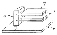
図18は、補助ホルダが配置されていない積層型の構成を示しており、ホルダ302に2つの振動子315が片持ち梁状に保持され、該ホルダ302が弾性体304に取り付けられる構成となっている。この構成では、複数の圧電セラミック振動子315の振動により、ホルダ302介して、弾性体304に振動伝達をおこなう場合、単数の圧電セラミック振動子を利用する場合と比較して、加振力が、圧電セラミック振動子の数に比例して、増大することが期待される。
FIG. 18 shows a stacked configuration in which an auxiliary holder is not disposed, and two
しかし実際には、圧電セラミック振動子の数から期待される加振力は得られない。この理由は次の通りである。すなわち、複数セラミック振動子の設置によりホルダ302の高さが高くなるため、圧電セラミック振動子の振動による慣性力の水平成分の影響が大きくなる。よって、ホルダ302が圧電セラミック振動子315との接合部近傍において水平方向に撓みやすくなり、弾性体304への振動エネルギーの伝達効率が悪くなるためである。また、各圧電振動子は、ホルダ802に接合される位置が、ホルダの高さ方向に異なるため、慣性力の寄与が各圧電セラミック振動子で異なり、各圧電セラミック振動子の振動の緩衝が起こり、その振動力は低下する。
However, in reality, the exciting force expected from the number of piezoelectric ceramic vibrators cannot be obtained. The reason is as follows. That is, since the height of the holder 302 is increased by installing a plurality of ceramic vibrators, the influence of the horizontal component of the inertial force due to the vibration of the piezoelectric ceramic vibrator is increased. Therefore, the holder 302 is easily bent in the horizontal direction in the vicinity of the joint with the piezoelectric
これに対して本実施形態の構成によれば、補助ホルダ13が設けられていることから、圧電セラミック振動子の振動による慣性力の水平成分によるホルダ62の水平方向の撓みが抑制される。また、弾性体14と接する面積の増大にともなう振動伝達効率の向上が実現される。さらには、上下に配置された各圧電セラミック振動子が補助ホルダ13を介して互いに加振されるため、各圧電セラミック振動子は安定した動作が可能になる。その結果、従来技術と比較して、最終的な加振力が飛躍的に増大する。
On the other hand, according to the configuration of the present embodiment, since the
以下、本発明の効果の詳細な説明を、実施例をもとにおこなう。なお、下記実施例中の「長さ」とは、図4に例示するX方向の長さを意図し、同様に、「幅」はY方向の長さ、「高さ」はZ方向の長さを意図するものとする。 Hereinafter, detailed description of the effects of the present invention will be made based on examples. Note that “length” in the following examples means the length in the X direction illustrated in FIG. 4, and similarly, “width” is the length in the Y direction, and “height” is the length in the Z direction. Is intended.
(実施例1)
実施例1として図4〜図6に示した第1の実施形態型の圧電アクチュエータ50A、50B、50Cを作製した。Example 1
As Example 1, the
圧電セラミック板16、17として、長さ25mm、幅5mm、厚さ0.2mmのセラミック板を用意し、両主面にAg電極を形成して分極処理を施した。シム板18として、長さ28mm、幅5mm、厚さ0.1mmの形状であるリン青銅板を用紙した。上記2枚の圧電セラミック板を、エポキシ樹脂でシム板18の両面に接着すると共に、所定の電気配線を形成して圧電セラミック振動子15を作製した。
As the piezoelectric
ホルダ12としては、ABS樹脂により作製した幅5mm、長さ4mm、高さ10mmの樹脂部材を用意した。振動子15とホルダ12との接着には、エポキシ樹脂を用いた。なお、ホルダ12は、振動を伝達させる電子機器に対して突起し、その底面は平坦である構造にした。
As the
補助ホルダ13として、幅5mm、長さ4mm、高さ2mmの形状であるシリコンゴムを3つ用意した。シリコンゴムの配置位置を異ならせて、3つの圧電アクチュエータ50A、50B、50Cを作製した。圧電アクチュエータ50Aでは、図4に示されているように、補助ホルダ13の端面(ホルダ12に対向する面)が、圧電セラミック板16、17の端面に揃うような位置(すなわち、端面から0mmの位置)に、補助ホルダ13を配置した。
As the
図5の圧電アクチュエータ50Bでは、圧電セラミック板16、17の端面から5mmの位置に、補助ホルダ13を配置した。図6の圧電アクチュエータ50Cでは、端面から10mmの位置に、補助ホルダ13を配置した。
In the piezoelectric actuator 50 </ b> B of FIG. 5, the
いずれの圧電アクチュエータ50A、50B、50Cにおいても、補助ホルダの底面とホルダの底面の高さが一致し、平坦であり、振動を伝播させる弾性体面に対してホルダ、補助ホルダが突起した構造にした。
In any of the
このようにして構成した圧電アクチュエータを、図9に示すような電子機器(携帯電話機)に搭載した。この携帯電話機70の構成自体は従来一般的なものであり、筐体72の1つの面に、液晶ディスプレイ71および入力キー73が設けられており、また、液晶ディスプレイ74側の端面にアンテナ74が配されている。図9(b)の断面図に示すように、携帯電話機内部には、電池76や電子回路基板79が配置されている。圧電アクチュエータの搭載位置は、符号77で示すように、ディスプレイとアンテナとの間であって筐体72の内側面とした。圧電アクチュエータのホルダおよび補助ホルダの接合位置は符号75にて示す箇所(液晶ディスプレイ上にある、筐体の一部を形成する液晶ディスプレイ保護板上)とした。
The piezoelectric actuator thus configured was mounted on an electronic device (mobile phone) as shown in FIG. The configuration itself of the
なお、筐体72としては厚み1mmのステンレス材料を用いた。筐体72の外形は、長さ50mm、幅50mm、厚さ20mmであった。圧電アクチュエータの固定には粘着材料を用いた。
As the
本発明に効果を検証するため、圧電アクチュエータに100Hz、実行値5Vの交流電界を印加し、携帯電話機の振動加速度を計測した。計測位置は、図9(b)の符号A、Bで示す位置であり、位置Aは、ディスプレイのほぼ中央、位置Bは電話機裏面における上記位置Aに対応する位置である。この計測にはレーザ型振動速度計を用いた。2箇所の計測により、筐体全体への振動伝達量の定量化をおこなった。 In order to verify the effect of the present invention, an AC electric field of 100 Hz and an execution value of 5 V was applied to the piezoelectric actuator, and the vibration acceleration of the mobile phone was measured. The measurement position is a position indicated by reference signs A and B in FIG. 9B, where the position A is substantially the center of the display, and the position B is a position corresponding to the position A on the back of the telephone. A laser-type vibration velocimeter was used for this measurement. The amount of vibration transmitted to the entire housing was quantified by measuring two locations.
振動加速度の他に、音圧の測定もおこなった。圧電アクチュエータに、1kHz、実行値5Vの交流電界を印加して、上記位置A、Bの2箇所から筐体垂直方向10cmの距離にマイクロホンを設置して音圧を計測した。これにより振動を音波に変換する音響性能を定量化した。 In addition to vibration acceleration, sound pressure was also measured. An AC electric field of 1 kHz and an effective value of 5 V was applied to the piezoelectric actuator, and a microphone was installed at a distance of 10 cm in the vertical direction of the casing from the two positions A and B, and the sound pressure was measured. This quantified the acoustic performance of converting vibration into sound waves.
上記のようにして計測した振動量および音圧を、従来技術である圧電アクチュエータを基準もしくは分母にして、その計測値の比を、規格振動量、規格音圧として表した。 The vibration amount and the sound pressure measured as described above were expressed as the standard vibration amount and the standard sound pressure, with the ratio of the measured values as a standard or denominator of the piezoelectric actuator as a conventional technique.
この結果を表1に示す。従来技術と比較して、本発明技術はいずれも規格振動量、規格音圧の向上が30%以上図られ、その効果は明らかである。 The results are shown in Table 1. Compared with the prior art, all of the techniques of the present invention improve the standard vibration amount and the standard sound pressure by 30% or more, and the effects are obvious.

(実施例2)
実施例2では、図8(a)、(b)に示したような、補助ホルダの長さを異ならせた2つの圧電アクチュエータ50D、50Eを2つ作製した。なお、これらのアクチュエータは補助ホルダの形状のみが異なるものであり、その他の構造部は上記実施例で作製したものと同じものを使用した。ちなみに、基本となる構成として先の実施例で作製した圧電アクチュエータ50Aも使用した。(Example 2)
In Example 2, two piezoelectric actuators 50D and 50E having different auxiliary holder lengths as shown in FIGS. 8A and 8B were produced. Note that these actuators differ only in the shape of the auxiliary holder, and the other structural parts were the same as those produced in the above examples. Incidentally, the
ここで、各アクチュエータ50、50D、50Eにおける補助ホルダの形状は次の通りである。 Here, the shape of the auxiliary holder in each actuator 50, 50D, 50E is as follows.
アクチュエータ50(補助ホルダ13)・・・幅5mm、長さ4mm、高さ2mm
アクチュエータ50D(補助ホルダ13’)・・・幅5mm、長さ8mm、高さ2mm
アクチュエータ50E(補助ホルダ13’’)・・・幅5mm、長さ12mm、高さ2mm
補助ホルダ13、13’、13’’の材質はいずれもシリコンゴムである。圧電アクチュエータ50D、50Eでは、上記実施例の圧電アクチュエータ50Aと同様、補助ホルダの端面と圧電セラミック板16、17の端面とが揃うような位置に、補助ホルダ13’、13’’を配置した。このとき、実施例1と同様に、補助ホルダの底面とホルダの底面の高さを一致させ、振動を伝達させたい筐体に対してホルダ、補助ホルダが突起する構成とした。Actuator 50 (auxiliary holder 13): width 5 mm, length 4 mm, height 2 mm
Actuator 50D (auxiliary holder 13 '): width 5mm, length 8mm, height 2mm
Actuator 50E (
The material of the
以上のようにして作製した圧電アクチュエータ50A、50D、50Eを、それぞれ、携帯電話機(図9参照)に搭載し、実施例1同様、振動量の測定と音圧の測定とをおこなった。その結果を表2に示す。本発明技術はいずれも振動量と音圧の向上が20%以上図られ、その効果は明らかである。
The
(実施例3)
実施例3では、図14に示した圧電アクチュエータ54A、54Bと、図12の圧電アクチュエータ52Bを作製した。なお、これらのアクチュエータは補助ホルダの形状のみが異なるものであり、その他の構造部は上記実施例1で作製したものと同じものを使用した。(Example 3)
In Example 3, the
ここで、各アクチュエータにおける補助ホルダの形状は次の通りである。 Here, the shape of the auxiliary holder in each actuator is as follows.
アクチュエータ54A(補助ホルダ83)・・・外形:幅5mm、長さ8mm、高さ2mm/スリット:底部中央にスリット幅2mm、深さ0.5mmのスリット83aを1つ形成した(なお、スリット83aは補助ホルダの図示手前側の面から奥側の面(不図示)まで一直線に形成した)。
アクチュエータ54B(補助ホルダ83’)・・・外形:幅5mm、長さ8mm、高さ2mm/スリット:底部中央にスリット幅2mm、深さ0.5mmのスリット83aを2つ形成した(なお、それぞれのスリット83aは補助ホルダの図示手前側の面から奥側の面(不図示)まで一直線に形成した)。より具体的には、各スリット83aは補助ホルダ底部中心位置から2mmの位置にそれぞれ形成した。
Actuator 54B (auxiliary holder 83 ') ··· Outer shape: width 5mm, length 8mm, height 2mm / slit: Two
なお、上記各アクチュエータ54A、54Bにおいても上記実施形態同様、補助ホルダの底面とホルダの底面の高さを一致させている。
In each of the
アクチュエータ52B・・・外形:幅7mm、長さ4mm、高さ10mm/貫通穴:幅7mm、長さ2mm、高さ6mm/材質:シリコンゴムである一体部材(ホルダ部材)を用意した。この部材は一体成形により作製したものである。このホルダ部材に、上記実施例1と同様の振動子15を取り付け、圧電アクチュエータ52Bとした。
Actuator 52B: Outline: width 7 mm, length 4 mm, height 10 mm / through hole: width 7 mm, length 2 mm, height 6 mm / material: an integral member (holder member) made of silicon rubber was prepared. This member is produced by integral molding. A
評価は、実施例1と同様に、図9の携帯電話に、4つの圧電アクチュエータを各々接合し、実施例1と同様の評価をおこなった。その結果を表3に示す。本発明に係る構成ではいずれも、振動量と音圧の向上が40%以上図られていた。 In the same manner as in Example 1, four piezoelectric actuators were joined to the mobile phone shown in FIG. 9, and the same evaluation as in Example 1 was performed. The results are shown in Table 3. In any of the configurations according to the present invention, the vibration amount and the sound pressure are improved by 40% or more.
(実施例4)
実施例4では、図16に示した圧電アクチュエータ56を作製した。Example 4
In Example 4, the
圧電セラミック板26、27として、長さ25mm、幅5mm、厚さ0.2mmのセラミック板を用意し、両主面にAg電極を形成して分極処理を施した。シム板28として、長さ35mm、幅5mm、厚さ0.1mmの形状であるリン青銅板を用紙した。上記2枚の圧電セラミック板を、エポキシ樹脂でシム板28の両面に接着すると共に、所定の電気配線を形成して圧電セラミック振動子25を作製した。最終的に、シム板28の領域28bがセラミック板26、27の端面から7mm突出する形態であった。
As the piezoelectric
ホルダ12は、実施例1と同じものを用意した。すなわち、ABS樹脂により作製した幅5mm、長さ4mm、高さ10mmの形状の部材である。補助ホルダ13はいずれもシリコンゴムであり、幅5mm、長さ4mm、高さ2mmの形状である。
The
この2つの補助ホルダを、図16(c)に示したように、ホルダ12側の圧電セラミック板端部の位置と、リン青銅板(28)の先端部位置に接合した。このとき、補助ホルダの底面とホルダの底面の高さを一致させている。
These two auxiliary holders were joined to the position of the end portion of the piezoelectric ceramic plate on the
評価は、実施例1と同様に、図9の携帯電話に、4つの圧電アクチュエータを、ホルダ・補助ホルダを介して各々接合して、実施例1と同様の評価をおこなった。その結果を表4に示す。本発明に係る構成ではいずれも振動量と音圧の向上が50%以上図られていた。 In the same manner as in Example 1, four piezoelectric actuators were joined to the mobile phone shown in FIG. 9 via a holder / auxiliary holder, and the same evaluation as in Example 1 was performed. The results are shown in Table 4. In any of the configurations according to the present invention, the vibration amount and the sound pressure are improved by 50% or more.
(実施例5)
実施例5では、図17に示した積層型の圧電アクチュエータ61を作製すると共に、それとは別に比較用のアクチュエータを構成した。各圧電セラミック振動子15として上記実施例1で作製したものと同じものを用意した。(Example 5)
In Example 5, the stacked
ホルダ62としては、ABS樹脂により作製した幅5mm、長さ4mm、高さ10mmの樹脂部材を用意し、高さ方向に2mmの距離をあけて溝(符号を付して示さず)を形成した。この溝にそれぞれに各振動子15をエポキシ樹脂を用いて固定した。
As the
補助ホルダ13として、樹脂モールド法の一体成形により幅5mm、長さ4mm、高さ2mmの形状をもつシリコンゴム製の補助ホルダを用意した。
As the
〔比較用アクチュエータ:従来技術複層〕
上記のようにして作製した、ホルダ62に2つの振動子15を固定しただけの構成のもの(すなわち補助ホルダを備えていない構成)を比較用アクチュエータ(「従来技術複層」と呼ぶ)として用意した。[Comparator: Conventional multi-layer]
Prepared as described above as a comparative actuator (referred to as “prior art multi-layer”) having a configuration in which the two
〔圧電アクチュエータ61〕
上記のようにして作製した構成(従来技術複層に相当)に対し、振動子15同士の間および振動子15と弾性体との間となる位置に上記補助ホルダ13を設け、本発明に係る圧電アクチュエータ61を構成した。補助ホルダ13の接着には、アクリル系接着剤を用いた。このとき、補助ホルダの底面とホルダの底面の高さを一致させている。[Piezoelectric actuator 61]
The
本発明に係る構成の加振力改善効果を確認するため、実施例1に記載の従来技術圧電アクチュエータを作製した(「従来技術単層」と称す)。 In order to confirm the effect of improving the excitation force of the configuration according to the present invention, the prior art piezoelectric actuator described in Example 1 was manufactured (referred to as “prior art single layer”).
評価は、実施例1と同様に、従来技術単層の圧電アクチュエータの振動速度および音圧を基準とした評価をおこなった。その結果を表5に示す。本発明に係る構成ではいずれも、従来技術単層圧電アクチュエータと比較して260%以上の特性向上が図られていた。しかし、従来技術複層の圧電アクチュエータは約130%の特性向上しか得られていない。このことから、従来技術の構成では振動エネルギーの損失が大きく、これに対して本発明に係る構成では、振動が効率的に伝播されることが明示された。 In the same manner as in Example 1, the evaluation was performed based on the vibration speed and sound pressure of the conventional single-layer piezoelectric actuator. The results are shown in Table 5. In any of the configurations according to the present invention, a characteristic improvement of 260% or more was achieved as compared with the conventional single-layer piezoelectric actuator. However, the conventional multi-layer piezoelectric actuator has only improved characteristics by about 130%. From this, it was clearly shown that vibration energy loss is large in the configuration of the prior art, whereas vibration is efficiently propagated in the configuration according to the present invention.
(実施例6)
実施例1に記載の圧電アクチュエータを搭載した携帯電話機(図9参照)において、加振器を用いて計測点A、Bに対して振動を付与し、そのとき圧電アクチュエータに生じる電圧値を測定した。また、各々の計測点から10cmの距離にスピーカを配置して携帯電話に向けて音を放射させ、そのとき圧電アクチュエータに生じる電圧値を測定した。携帯電話機に対して付与する振動は100Hz、0.1m/sの振動速度とし、音波は1kHz、90dB音圧レベルとした。(Example 6)
In a cellular phone (see FIG. 9) equipped with the piezoelectric actuator described in Example 1, vibration was applied to measurement points A and B using a vibrator, and the voltage value generated in the piezoelectric actuator was measured at that time. . In addition, a speaker was arranged at a distance of 10 cm from each measurement point to emit sound toward the mobile phone, and the voltage value generated in the piezoelectric actuator at that time was measured. The vibration applied to the mobile phone was 100 Hz and a vibration speed of 0.1 m / s, and the sound wave was 1 kHz and a sound pressure level of 90 dB.
このとき発生する圧電アクチュエータの電圧値を、従来技術と基準として、規格化振動感度、規格化音圧感度として測定し、その結果を表6に示す。実施例1の規格化振動速度、規格化音圧の結果と近似しており、振動源また振動センサとして可逆性をもち、さらには本発明の効果が高いことが示された。以上の実施例で示したように、本発明によれば、圧電アクチュエータの加振力向上が図られ、電子機器に適用し、大きな振動量が得られ、その工業的価値は多大である。 The voltage values of the piezoelectric actuator generated at this time were measured as normalized vibration sensitivity and normalized sound pressure sensitivity based on the prior art and the standard, and the results are shown in Table 6. The results were close to the results of the normalized vibration speed and the normalized sound pressure of Example 1, and were shown to have reversibility as a vibration source or a vibration sensor and further to have a high effect of the present invention. As shown in the above embodiments, according to the present invention, the excitation force of the piezoelectric actuator can be improved, and can be applied to an electronic device to obtain a large amount of vibration, which has a great industrial value.
(実施例7)
実施例5に記載の圧電アクチュエータを搭載した携帯電話機(図9参照)において、上記実施例同様、加振器を用いて計測点A、Bに対して振動を付与し、そのとき圧電アクチュエータに生じる電圧値を測定した。また、各々の計測点から10cmの距離にスピーカを配置して携帯電話に向けて音を放射させ、そのとき圧電アクチュエータに生じる電圧値を測定した。携帯電話機に対して付与する振動は、100Hz、0.1m/sの振動速度とし、音波は1kHz、90dB音圧レベルとした。(Example 7)
In the cellular phone (see FIG. 9) equipped with the piezoelectric actuator described in the fifth embodiment, vibration is applied to the measurement points A and B using the vibrator similar to the above-described embodiment, and the vibration is generated in the piezoelectric actuator. The voltage value was measured. In addition, a speaker was arranged at a distance of 10 cm from each measurement point to emit sound toward the mobile phone, and the voltage value generated in the piezoelectric actuator at that time was measured. The vibration applied to the mobile phone was 100 Hz and a vibration velocity of 0.1 m / s, and the sound wave was 1 kHz and a sound pressure level of 90 dB.
このとき発生する圧電アクチュエータの電圧値を、従来技術と基準として、規格化振動感度、規格化音圧感度として測定し、その結果を表7に示す。実施例5の規格化振動速度、規格化音圧の結果と近似しており、振動源また振動センサとして可逆性をもち、さらには本発明の効果が高いことが示された。以上の実施例で示したように、本発明によれば、圧電アクチュエータの加振力向上とセンサ感度向上が図られ、電子機器に適用する工業的価値は多大である。 The voltage values of the piezoelectric actuator generated at this time were measured as normalized vibration sensitivity and normalized sound pressure sensitivity based on the prior art and the standard, and the results are shown in Table 7. It was approximated to the results of the normalized vibration speed and the normalized sound pressure of Example 5, and was shown to have reversibility as a vibration source or a vibration sensor, and to have a high effect of the present invention. As shown in the above embodiments, according to the present invention, the excitation force and the sensor sensitivity of the piezoelectric actuator can be improved, and the industrial value applied to the electronic device is great.
11、21、31、41 隙間
12、22、32、42、62 ホルダ
13、23、33、43、83、93 補助ホルダ
14 弾性体
15、25 圧電セラミック振動子
16、17、26、27 圧電セラミック板
18、28 シム板
18a 領域
39、49 接続部
41 貫通穴
50〜56、61〜63 圧電アクチュエータ
70 携帯電話機
83a スリット11, 21, 31, 41
Claims (14)
前記圧電セラミック振動子から延在する前記シム体の端部を保持し、前記圧電セラミック振動子の撓み振動を対象物に伝播させるホルダと、 A holder for holding an end portion of the shim body extending from the piezoelectric ceramic vibrator and propagating flexural vibration of the piezoelectric ceramic vibrator to an object;
前記ホルダとの間に隙間を空けて前記圧電体層に固定された少なくとも1つの補助ホルダとを有し、 Having at least one auxiliary holder fixed to the piezoelectric layer with a gap between the holder and
前記補助ホルダを介して、前記圧電セラミック振動子の撓み振動の一部が前記対象物に伝播されるように構成される、圧電アクチュエータ。 A piezoelectric actuator configured such that a part of flexural vibration of the piezoelectric ceramic vibrator is propagated to the object via the auxiliary holder.
Priority Applications (1)
| Application Number | Priority Date | Filing Date | Title |
|---|---|---|---|
| JP2008503768A JP5169817B2 (en) | 2006-03-07 | 2007-02-20 | Piezoelectric actuator and electronic device |
Applications Claiming Priority (4)
| Application Number | Priority Date | Filing Date | Title |
|---|---|---|---|
| JP2006061161 | 2006-03-07 | ||
| JP2006061161 | 2006-03-07 | ||
| JP2008503768A JP5169817B2 (en) | 2006-03-07 | 2007-02-20 | Piezoelectric actuator and electronic device |
| PCT/JP2007/053032 WO2007102305A1 (en) | 2006-03-07 | 2007-02-20 | Piezoelectric actuator and electronic device |
Publications (2)
| Publication Number | Publication Date |
|---|---|
| JPWO2007102305A1 JPWO2007102305A1 (en) | 2009-07-23 |
| JP5169817B2 true JP5169817B2 (en) | 2013-03-27 |
Family
ID=38474747
Family Applications (1)
| Application Number | Title | Priority Date | Filing Date |
|---|---|---|---|
| JP2008503768A Expired - Fee Related JP5169817B2 (en) | 2006-03-07 | 2007-02-20 | Piezoelectric actuator and electronic device |
Country Status (3)
| Country | Link |
|---|---|
| US (1) | US7750540B2 (en) |
| JP (1) | JP5169817B2 (en) |
| WO (1) | WO2007102305A1 (en) |
Cited By (2)
| Publication number | Priority date | Publication date | Assignee | Title |
|---|---|---|---|---|
| KR20200105911A (en) * | 2018-06-25 | 2020-09-09 | 구글 엘엘씨 | Actuator for distributed mode loudspeaker with extended damper and system comprising same |
| JP7083121B1 (en) | 2021-03-31 | 2022-06-10 | NatureArchitects株式会社 | Structures, vibration devices and sensory acoustic devices |
Families Citing this family (37)
| Publication number | Priority date | Publication date | Assignee | Title |
|---|---|---|---|---|
| US10203873B2 (en) | 2007-09-19 | 2019-02-12 | Apple Inc. | Systems and methods for adaptively presenting a keyboard on a touch-sensitive display |
| US9489086B1 (en) | 2013-04-29 | 2016-11-08 | Apple Inc. | Finger hover detection for improved typing |
| US9454270B2 (en) | 2008-09-19 | 2016-09-27 | Apple Inc. | Systems and methods for detecting a press on a touch-sensitive surface |
| US10126942B2 (en) * | 2007-09-19 | 2018-11-13 | Apple Inc. | Systems and methods for detecting a press on a touch-sensitive surface |
| US9110590B2 (en) * | 2007-09-19 | 2015-08-18 | Typesoft Technologies, Inc. | Dynamically located onscreen keyboard |
| JP5304791B2 (en) * | 2008-08-27 | 2013-10-02 | 株式会社村田製作所 | Vibration device |
| US9069390B2 (en) | 2008-09-19 | 2015-06-30 | Typesoft Technologies, Inc. | Systems and methods for monitoring surface sanitation |
| JP2010273408A (en) * | 2009-05-19 | 2010-12-02 | Emprie Technology Development LLC | Power device, method of generating power, and method of manufacturing the power device |
| JP2011043925A (en) * | 2009-08-19 | 2011-03-03 | Nissha Printing Co Ltd | Flexurally vibrating actuator and touch panel with tactile sensation feedback function using the same |
| KR101133348B1 (en) * | 2009-10-12 | 2012-04-09 | 삼성전기주식회사 | Haptic feedback device and electronic device |
| CN102597932B (en) * | 2009-11-19 | 2014-12-10 | 株式会社村田制作所 | Electronic device with touch panel |
| JP5440422B2 (en) * | 2010-06-30 | 2014-03-12 | 日本電気株式会社 | Oscillator |
| JP5488266B2 (en) * | 2010-06-30 | 2014-05-14 | 日本電気株式会社 | Oscillator |
| US10429929B2 (en) * | 2010-09-24 | 2019-10-01 | Blackberry Limited | Piezoelectric actuator apparatus and methods |
| JP2012120097A (en) * | 2010-12-03 | 2012-06-21 | Kyocera Corp | Piezoelectric electronic component and electronic device |
| EP2693772B1 (en) * | 2011-03-31 | 2016-09-14 | NEC Corporation | Oscillator |
| JP5926950B2 (en) | 2011-12-22 | 2016-05-25 | 京セラ株式会社 | Electronics |
| US9104260B2 (en) | 2012-04-10 | 2015-08-11 | Typesoft Technologies, Inc. | Systems and methods for detecting a press on a touch-sensitive surface |
| CN103252313B (en) * | 2013-04-19 | 2015-10-28 | 南京航空航天大学 | Ultralight Eddy Current Excited device and vibration measuring method |
| JP5815612B2 (en) * | 2013-07-29 | 2015-11-17 | 京セラ株式会社 | Electronics |
| US10289302B1 (en) | 2013-09-09 | 2019-05-14 | Apple Inc. | Virtual keyboard animation |
| US9872110B2 (en) * | 2013-10-30 | 2018-01-16 | Kyocera Corporation | Sound generator and sound generation system |
| TWI519758B (en) * | 2013-12-02 | 2016-02-01 | Su Hsien Chin | Heat sink |
| JPWO2016080387A1 (en) * | 2014-11-21 | 2017-09-21 | 株式会社トーキン | Sound generator and electronic device |
| TWM521322U (en) * | 2015-12-18 | 2016-05-01 | Xian-Qin Su | Heat dissipation device and swing structure thereof |
| TWM534478U (en) * | 2016-10-14 | 2016-12-21 | Jetvox Acoustic Corp | Mobile communication device and dual-frequency receiver used therein |
| KR102384033B1 (en) * | 2017-03-20 | 2022-04-06 | 엘지전자 주식회사 | Display Apparatus |
| DE112017007977A5 (en) * | 2017-08-25 | 2020-06-04 | iNDTact GmbH | MOBILE DEVICE WITH A SENSOR |
| CN107453645A (en) * | 2017-09-14 | 2017-12-08 | 苏州迈客荣自动化技术有限公司 | Piezoelectric actuator |
| JP7017578B2 (en) * | 2017-10-12 | 2022-02-08 | 富士フイルム株式会社 | Manufacturing method of power generation element, power generation element and power generation device |
| US10681471B2 (en) * | 2017-12-22 | 2020-06-09 | Google Llc | Two-dimensional distributed mode actuator |
| JP2019146108A (en) * | 2018-02-23 | 2019-08-29 | 京セラ株式会社 | Acoustic generator and electronic apparatus |
| TWI667871B (en) * | 2018-08-07 | 2019-08-01 | 國立交通大學 | Fan device |
| US10848875B2 (en) * | 2018-11-30 | 2020-11-24 | Google Llc | Reinforced actuators for distributed mode loudspeakers |
| US10462574B1 (en) | 2018-11-30 | 2019-10-29 | Google Llc | Reinforced actuators for distributed mode loudspeakers |
| JP2022050037A (en) * | 2020-09-17 | 2022-03-30 | 株式会社東芝 | Magnetic disk device |
| KR20240007931A (en) * | 2021-11-10 | 2024-01-17 | 가부시키가이샤 미치히로 | SoT module |
Citations (3)
| Publication number | Priority date | Publication date | Assignee | Title |
|---|---|---|---|---|
| JPH09271096A (en) * | 1996-03-28 | 1997-10-14 | Whitaker Corp:The | Piezoelectric speaker |
| JP2002507849A (en) * | 1998-03-20 | 2002-03-12 | アクティブ コントロール エキスパーツ,インコーポレイテッド | Inertial / acoustic units and configurations |
| JP2005045691A (en) * | 2003-07-24 | 2005-02-17 | Taiyo Yuden Co Ltd | Piezoelectric vibrator |
Family Cites Families (2)
| Publication number | Priority date | Publication date | Assignee | Title |
|---|---|---|---|---|
| JPH10340086A (en) * | 1997-06-09 | 1998-12-22 | Seiko Epson Corp | Sounder using piezoelectric element and electronic device having the sounder |
| JP2005160028A (en) * | 2003-10-27 | 2005-06-16 | Nec Tokin Corp | Bending vibration type actuator |
-
2007
- 2007-02-20 US US12/281,974 patent/US7750540B2/en not_active Expired - Fee Related
- 2007-02-20 WO PCT/JP2007/053032 patent/WO2007102305A1/en active Application Filing
- 2007-02-20 JP JP2008503768A patent/JP5169817B2/en not_active Expired - Fee Related
Patent Citations (3)
| Publication number | Priority date | Publication date | Assignee | Title |
|---|---|---|---|---|
| JPH09271096A (en) * | 1996-03-28 | 1997-10-14 | Whitaker Corp:The | Piezoelectric speaker |
| JP2002507849A (en) * | 1998-03-20 | 2002-03-12 | アクティブ コントロール エキスパーツ,インコーポレイテッド | Inertial / acoustic units and configurations |
| JP2005045691A (en) * | 2003-07-24 | 2005-02-17 | Taiyo Yuden Co Ltd | Piezoelectric vibrator |
Cited By (9)
| Publication number | Priority date | Publication date | Assignee | Title |
|---|---|---|---|---|
| KR20200105911A (en) * | 2018-06-25 | 2020-09-09 | 구글 엘엘씨 | Actuator for distributed mode loudspeaker with extended damper and system comprising same |
| KR102340299B1 (en) * | 2018-06-25 | 2021-12-16 | 구글 엘엘씨 | Actuator for distributed mode loudspeaker with extended damper and system comprising same |
| KR20210154879A (en) * | 2018-06-25 | 2021-12-21 | 구글 엘엘씨 | Actuator for distributed mode loudspeaker with extended damper and systems including the same |
| KR102489468B1 (en) | 2018-06-25 | 2023-01-17 | 구글 엘엘씨 | Actuator for distributed mode loudspeaker with extended damper and systems including the same |
| JP7083121B1 (en) | 2021-03-31 | 2022-06-10 | NatureArchitects株式会社 | Structures, vibration devices and sensory acoustic devices |
| WO2022208935A1 (en) * | 2021-03-31 | 2022-10-06 | NatureArchitects株式会社 | Structure, vibration device, sensory acoustic device, structure design method, structure manufacturing method, and program |
| WO2022210846A1 (en) * | 2021-03-31 | 2022-10-06 | NatureArchitects株式会社 | Structural body, vibrating device, and sensory acoustic apparatus |
| JP2022159139A (en) * | 2021-03-31 | 2022-10-17 | NatureArchitects株式会社 | Structure, vibration device and body sensation acoustic unit |
| JP2022158868A (en) * | 2021-03-31 | 2022-10-17 | NatureArchitects株式会社 | Structure, vibration device, body sensation acoustic unit, structure design method, structure production method and program |
Also Published As
| Publication number | Publication date |
|---|---|
| US20090045700A1 (en) | 2009-02-19 |
| WO2007102305A1 (en) | 2007-09-13 |
| US7750540B2 (en) | 2010-07-06 |
| JPWO2007102305A1 (en) | 2009-07-23 |
Similar Documents
| Publication | Publication Date | Title |
|---|---|---|
| JP5169817B2 (en) | Piezoelectric actuator and electronic device | |
| JP5636796B2 (en) | Microphone unit | |
| JP3907616B2 (en) | Electronics | |
| JP5558577B2 (en) | Piezoelectric vibration device and portable terminal using the same | |
| KR101524103B1 (en) | Piezoelectric vibration device and portable terminal | |
| JP2011091719A (en) | Flexural oscillating actuator | |
| JP6053827B2 (en) | SOUND GENERATOR AND ELECTRONIC DEVICE USING THE SAME | |
| JPWO2008146678A1 (en) | Piezoelectric actuator and electronic device | |
| WO2007026736A1 (en) | Piezoelectric actuator, acoustic element, and electronic device | |
| WO2005024966A1 (en) | Piezoelectric ceramic element and portable device | |
| JPWO2006075440A1 (en) | Piezoelectric actuator and electronic device | |
| JP5939160B2 (en) | Oscillator and electronic device | |
| JP5636795B2 (en) | Microphone unit | |
| JP4830858B2 (en) | Piezoelectric ceramic actuator and portable device | |
| JP2012015758A (en) | Oscillator, method for manufacturing the same and electronic device | |
| JP6304168B2 (en) | Piezoelectric module | |
| JP5934145B2 (en) | Mobile device | |
| JPWO2014061584A1 (en) | Electroacoustic transducer, manufacturing method thereof, and electronic apparatus using the electroacoustic transducer | |
| JP5419254B2 (en) | Microphone unit | |
| JP4531543B2 (en) | Acoustic sensor | |
| JP5659598B2 (en) | Oscillator | |
| WO2014083902A1 (en) | Acoustic generator and electronic apparatus using same | |
| JP2012134594A (en) | Oscillation device and electronic apparatus | |
| JP2012015756A (en) | Electronic apparatus and oscillation unit |
Legal Events
| Date | Code | Title | Description |
|---|---|---|---|
| RD01 | Notification of change of attorney |
Free format text: JAPANESE INTERMEDIATE CODE: A7421 Effective date: 20091015 |
|
| A621 | Written request for application examination |
Free format text: JAPANESE INTERMEDIATE CODE: A621 Effective date: 20100115 |
|
| RD01 | Notification of change of attorney |
Free format text: JAPANESE INTERMEDIATE CODE: A7421 Effective date: 20110705 |
|
| A131 | Notification of reasons for refusal |
Free format text: JAPANESE INTERMEDIATE CODE: A131 Effective date: 20120321 |
|
| A521 | Request for written amendment filed |
Free format text: JAPANESE INTERMEDIATE CODE: A523 Effective date: 20120521 |
|
| A01 | Written decision to grant a patent or to grant a registration (utility model) |
Free format text: JAPANESE INTERMEDIATE CODE: A01 Effective date: 20121204 |
|
| A61 | First payment of annual fees (during grant procedure) |
Free format text: JAPANESE INTERMEDIATE CODE: A61 Effective date: 20121217 |
|
| S111 | Request for change of ownership or part of ownership |
Free format text: JAPANESE INTERMEDIATE CODE: R313113 |
|
| R350 | Written notification of registration of transfer |
Free format text: JAPANESE INTERMEDIATE CODE: R350 |
|
| R250 | Receipt of annual fees |
Free format text: JAPANESE INTERMEDIATE CODE: R250 |
|
| R250 | Receipt of annual fees |
Free format text: JAPANESE INTERMEDIATE CODE: R250 |
|
| LAPS | Cancellation because of no payment of annual fees |