WO2014083902A1 - Acoustic generator and electronic apparatus using same - Google Patents
Acoustic generator and electronic apparatus using same Download PDFInfo
- Publication number
- WO2014083902A1 WO2014083902A1 PCT/JP2013/073457 JP2013073457W WO2014083902A1 WO 2014083902 A1 WO2014083902 A1 WO 2014083902A1 JP 2013073457 W JP2013073457 W JP 2013073457W WO 2014083902 A1 WO2014083902 A1 WO 2014083902A1
- Authority
- WO
- WIPO (PCT)
- Prior art keywords
- external space
- sound
- exciter
- exposed
- vibration
- Prior art date
Links
- 230000010355 oscillation Effects 0.000 abstract 5
- 239000011347 resin Substances 0.000 description 17
- 229920005989 resin Polymers 0.000 description 17
- 239000000463 material Substances 0.000 description 14
- 239000004020 conductor Substances 0.000 description 7
- 229910052751 metal Inorganic materials 0.000 description 7
- 239000002184 metal Substances 0.000 description 7
- 239000000919 ceramic Substances 0.000 description 5
- 230000006866 deterioration Effects 0.000 description 5
- 230000000694 effects Effects 0.000 description 4
- 239000000853 adhesive Substances 0.000 description 3
- 230000001070 adhesive effect Effects 0.000 description 3
- 238000010586 diagram Methods 0.000 description 3
- 230000002093 peripheral effect Effects 0.000 description 3
- XEEYBQQBJWHFJM-UHFFFAOYSA-N Iron Chemical compound [Fe] XEEYBQQBJWHFJM-UHFFFAOYSA-N 0.000 description 2
- KDLHZDBZIXYQEI-UHFFFAOYSA-N Palladium Chemical compound [Pd] KDLHZDBZIXYQEI-UHFFFAOYSA-N 0.000 description 2
- XUIMIQQOPSSXEZ-UHFFFAOYSA-N Silicon Chemical compound [Si] XUIMIQQOPSSXEZ-UHFFFAOYSA-N 0.000 description 2
- BQCADISMDOOEFD-UHFFFAOYSA-N Silver Chemical compound [Ag] BQCADISMDOOEFD-UHFFFAOYSA-N 0.000 description 2
- 230000005520 electrodynamics Effects 0.000 description 2
- 230000005484 gravity Effects 0.000 description 2
- 229910052451 lead zirconate titanate Inorganic materials 0.000 description 2
- 239000007769 metal material Substances 0.000 description 2
- 230000004048 modification Effects 0.000 description 2
- 238000012986 modification Methods 0.000 description 2
- -1 polyethylene Polymers 0.000 description 2
- 229910052710 silicon Inorganic materials 0.000 description 2
- 239000010703 silicon Substances 0.000 description 2
- 239000002002 slurry Substances 0.000 description 2
- 230000005236 sound signal Effects 0.000 description 2
- 229920003002 synthetic resin Polymers 0.000 description 2
- 239000000057 synthetic resin Substances 0.000 description 2
- 239000004925 Acrylic resin Substances 0.000 description 1
- 229920000178 Acrylic resin Polymers 0.000 description 1
- 239000004698 Polyethylene Substances 0.000 description 1
- 239000004642 Polyimide Substances 0.000 description 1
- 239000004743 Polypropylene Substances 0.000 description 1
- 239000004793 Polystyrene Substances 0.000 description 1
- 239000011230 binding agent Substances 0.000 description 1
- 150000001875 compounds Chemical class 0.000 description 1
- 230000008602 contraction Effects 0.000 description 1
- 238000005520 cutting process Methods 0.000 description 1
- 238000005238 degreasing Methods 0.000 description 1
- 239000002270 dispersing agent Substances 0.000 description 1
- 229920006351 engineering plastic Polymers 0.000 description 1
- 239000003822 epoxy resin Substances 0.000 description 1
- 239000000835 fiber Substances 0.000 description 1
- 238000010304 firing Methods 0.000 description 1
- 239000011521 glass Substances 0.000 description 1
- 229910052742 iron Inorganic materials 0.000 description 1
- HFGPZNIAWCZYJU-UHFFFAOYSA-N lead zirconate titanate Chemical compound [O-2].[O-2].[O-2].[O-2].[O-2].[Ti+4].[Zr+4].[Pb+2] HFGPZNIAWCZYJU-UHFFFAOYSA-N 0.000 description 1
- WABPQHHGFIMREM-UHFFFAOYSA-N lead(0) Chemical compound [Pb] WABPQHHGFIMREM-UHFFFAOYSA-N 0.000 description 1
- 150000002739 metals Chemical class 0.000 description 1
- 229910052763 palladium Inorganic materials 0.000 description 1
- 239000004033 plastic Substances 0.000 description 1
- 229920003023 plastic Polymers 0.000 description 1
- 239000004014 plasticizer Substances 0.000 description 1
- 229920000647 polyepoxide Polymers 0.000 description 1
- 229920001225 polyester resin Polymers 0.000 description 1
- 239000004645 polyester resin Substances 0.000 description 1
- 229920000573 polyethylene Polymers 0.000 description 1
- 229920001721 polyimide Polymers 0.000 description 1
- 229920001155 polypropylene Polymers 0.000 description 1
- 229920002223 polystyrene Polymers 0.000 description 1
- 239000000843 powder Substances 0.000 description 1
- 229910052709 silver Inorganic materials 0.000 description 1
- 239000004332 silver Substances 0.000 description 1
- 239000002904 solvent Substances 0.000 description 1
- 229910001220 stainless steel Inorganic materials 0.000 description 1
- 239000010935 stainless steel Substances 0.000 description 1
- 229910052721 tungsten Inorganic materials 0.000 description 1
- 239000010937 tungsten Substances 0.000 description 1
- 238000005406 washing Methods 0.000 description 1
- 239000002023 wood Substances 0.000 description 1
Images


Classifications
-
- H—ELECTRICITY
- H04—ELECTRIC COMMUNICATION TECHNIQUE
- H04R—LOUDSPEAKERS, MICROPHONES, GRAMOPHONE PICK-UPS OR LIKE ACOUSTIC ELECTROMECHANICAL TRANSDUCERS; DEAF-AID SETS; PUBLIC ADDRESS SYSTEMS
- H04R7/00—Diaphragms for electromechanical transducers; Cones
- H04R7/02—Diaphragms for electromechanical transducers; Cones characterised by the construction
- H04R7/04—Plane diaphragms
- H04R7/045—Plane diaphragms using the distributed mode principle, i.e. whereby the acoustic radiation is emanated from uniformly distributed free bending wave vibration induced in a stiff panel and not from pistonic motion
-
- H—ELECTRICITY
- H04—ELECTRIC COMMUNICATION TECHNIQUE
- H04R—LOUDSPEAKERS, MICROPHONES, GRAMOPHONE PICK-UPS OR LIKE ACOUSTIC ELECTROMECHANICAL TRANSDUCERS; DEAF-AID SETS; PUBLIC ADDRESS SYSTEMS
- H04R17/00—Piezoelectric transducers; Electrostrictive transducers
-
- H—ELECTRICITY
- H04—ELECTRIC COMMUNICATION TECHNIQUE
- H04R—LOUDSPEAKERS, MICROPHONES, GRAMOPHONE PICK-UPS OR LIKE ACOUSTIC ELECTROMECHANICAL TRANSDUCERS; DEAF-AID SETS; PUBLIC ADDRESS SYSTEMS
- H04R2499/00—Aspects covered by H04R or H04S not otherwise provided for in their subgroups
- H04R2499/10—General applications
- H04R2499/11—Transducers incorporated or for use in hand-held devices, e.g. mobile phones, PDA's, camera's
-
- H—ELECTRICITY
- H04—ELECTRIC COMMUNICATION TECHNIQUE
- H04R—LOUDSPEAKERS, MICROPHONES, GRAMOPHONE PICK-UPS OR LIKE ACOUSTIC ELECTROMECHANICAL TRANSDUCERS; DEAF-AID SETS; PUBLIC ADDRESS SYSTEMS
- H04R2499/00—Aspects covered by H04R or H04S not otherwise provided for in their subgroups
- H04R2499/10—General applications
- H04R2499/15—Transducers incorporated in visual displaying devices, e.g. televisions, computer displays, laptops
-
- H—ELECTRICITY
- H04—ELECTRIC COMMUNICATION TECHNIQUE
- H04R—LOUDSPEAKERS, MICROPHONES, GRAMOPHONE PICK-UPS OR LIKE ACOUSTIC ELECTROMECHANICAL TRANSDUCERS; DEAF-AID SETS; PUBLIC ADDRESS SYSTEMS
- H04R31/00—Apparatus or processes specially adapted for the manufacture of transducers or diaphragms therefor
- H04R31/003—Apparatus or processes specially adapted for the manufacture of transducers or diaphragms therefor for diaphragms or their outer suspension
Definitions
- the present invention relates to an acoustic generator and an electronic device using the same.
- the above-described conventional speaker has a problem in that the sound quality deteriorates due to particularly low-pitched sound on the front side of the diaphragm due to the reverse phase sound generated from the back surface of the diaphragm. Further, when a baffle board is installed to prevent the reverse phase sound generated from the back surface of the diaphragm from entering the front side, there is a problem that the sound generator is increased in size.
- the present invention has been devised in view of such problems in the prior art, and an object thereof is to provide an acoustic generator capable of generating sound of good sound quality and an electronic device using the same. There is to do.
- the sound generator of the present invention is a sound generator for radiating sound to an external space, and an exciter that vibrates when an electric signal is inputted thereto, and a vibration plate that is attached with the exciter and vibrates together with the exciter And at least a shielding body that is disposed at a distance from the vibrating portion and shields a part of the first surface that is one main surface of the vibrating portion from the external space.
- the area of the first portion, which is the portion exposed to the external space on the first surface of the vibrating portion is S1
- the external space on the second surface that is the other main surface of the vibrating portion is On the other hand, when the area of the second portion, which is the exposed portion, is S2, 0 ⁇ S1 ⁇ S2.
- the electronic device of the present invention includes at least the sound generator and an electronic circuit connected to the sound generator, and has a function of generating sound from the sound generator. is there.
- the sound generator of the present invention it is possible to obtain a sound generator that can generate sound of good sound quality.
- the electronic device of the present invention it is possible to obtain an electronic device capable of generating sound with good sound quality.
- FIG. 3 is a cross-sectional view taken along line A-A ′ of FIG. 2. It is a top view which shows typically the acoustic generator of the 2nd example of embodiment of this invention. It is a top view which shows typically the acoustic generator of the 2nd example of embodiment of this invention.
- FIG. 6 is a sectional view taken along line B-B ′ of FIG. 5. It is a top view which shows typically the acoustic generator of the 3rd example of embodiment of this invention.
- FIG. 9 is a cross-sectional view taken along line C-C ′ of FIG. 8.
- FIG. 9 is a sectional view taken along line D-D ′ of FIG. 8.
- FIG. 13 is a sectional view taken along line E-E ′ of FIG. 12.
- FIG. 13 is a cross-sectional view taken along line F-F ′ in FIG. 12. It is a block diagram which shows the structure of the electronic device of the 5th example of embodiment of this invention.
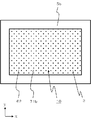
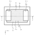
- FIG. 1 and 2 are plan views schematically showing a sound generator of a first example of an embodiment of the present invention.
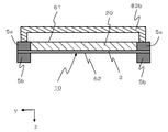
- 3 is a cross-sectional view taken along line AA ′ in FIG.
- the sound generator of this example includes an exciter 1, a film 3, frame members 5a and 5b, a resin layer 20, and shields 81a and 81b. .
- the frame members 5a and 5b have a rectangular frame shape.
- the outer periphery of the film 3 is sandwiched between the frame members 5a and 5b, and the film 3 is fixed in a tensioned state.
- the material and shape of the frame members 5a and 5b are not particularly limited as long as they are more difficult to deform than the film 3 and the resin layer 20.
- the frame members 5a and 5b can be formed using hard resin, plastic, engineering plastic, ceramics, metal, or the like.
- a stainless steel material having a thickness of 100 to 1000 ⁇ m can be preferably used.
- the inner shape of the frame members 5a and 5b is not limited to a rectangular shape, and may be an ellipse or a rhombus.
- the frame member 5b is not essential, and when the frame member 5b is not provided, for example, the film 3 may be bonded to the surface in the + z direction of the frame member 5a.
- the film 3 is fixed in such a manner that the peripheral edge of the rectangular shape is sandwiched and fixed by the frame members 5a and 5b as a whole in a state where tension is applied in the plane direction, and is supported by the frame members 5a and 5b so as to vibrate. Yes. That is, the vibrable portion located inside the frame members 5 a and 5 b in the film 3 functions as a diaphragm that is attached with the exciter 1 and vibrates together with the exciter 1.
- the thickness of the film 3 is, for example, 10 to 200 ⁇ m.
- the film 3 can be formed using resin, such as polyethylene, a polyimide, a polypropylene, a polystyrene, for example.
- the film 3 may be made of paper made of pulp, fiber, or the like.
- the exciter 1 is a piezoelectric element having a plate shape whose upper and lower main surfaces (both end surfaces in the z-axis direction in the figure) are rectangular.
- the exciter 1 includes a laminate in which piezoelectric layers made of piezoelectric ceramics and internal electrode layers are alternately laminated, and upper and lower surfaces of the laminate (both ends in the z-axis direction in the figure).
- Surface electrode layer and a pair of terminal electrodes provided on both end faces in the longitudinal direction (x-axis direction in the figure) of the laminate.
- the surface electrode and the internal electrode layer are alternately drawn to both end faces in the longitudinal direction (x-axis direction in the drawing) of the multilayer body, and are connected to the terminal electrodes, respectively. Then, an electrical signal is applied to the pair of terminal electrodes via a wiring (not shown).
- the exciter 1 is a bimorph type piezoelectric element. When an electric signal is input, expansion and contraction are reversed between one side and the other side in the thickness direction (z-axis direction in the figure) at an arbitrary moment. It is supposed to be. Thus, the exciter 1 receives an electric signal and bends and vibrates in the z-axis direction in the figure.
- the main surface of the exciter 1 on the film 3 side and the film 3 are bonded to each other with a known adhesive such as an epoxy resin, a silicon resin, or a polyester resin, or a double-sided tape.
- the diaphragm formed by the inner portions of the frame members 5 a and 5 b of the film 3 also vibrates together with the exciter 1.
- the exciter 1 for example, a monomorph type vibration element configured by bonding a piezoelectric element that receives an electric signal to expand and contract and vibrates and a metal plate may be used.
- Piezoelectric layers of the exciter 1 include piezoelectric materials conventionally used such as lead-free piezoelectric materials such as lead zirconate (PZ), lead zirconate titanate (PZT), Bi layered compounds, and tungsten bronze structure compounds. Ceramics can be used.
- the thickness of one piezoelectric layer is desirably about 10 to 100 ⁇ m from the viewpoint of low voltage driving.
- the piezoelectric d31 constant of the piezoelectric layer is preferably 180 pm / V or more.
- the internal electrode layer of the exciter 1 various known metal materials can be used. For example, when an internal electrode layer containing a metal component composed of silver and palladium and a material component constituting the piezoelectric layer is used, stress due to a difference in thermal expansion between the piezoelectric layer and the internal electrode layer can be reduced. Alternatively, other materials may be used.
- the surface electrode layer and the terminal electrode of the exciter 1 can be formed using various known metal materials. For example, when a material containing a silver metal component and a glass component is used, adhesion between the piezoelectric layer and internal electrode layer and the surface electrode layer and terminal electrode can be improved. May be used.
- the resin layer 20 is filled over the entire inside of the frame member 5a so that the exciter 1 is embedded.
- the resin layer 20 can be formed using various known materials.
- a resin such as an acrylic resin or a silicon resin, rubber, or the like can be used.
- a material having a Young's modulus in the range of 1 MPa to 1 GPa is desirable.
- the thickness of the resin layer 20 is desirably a thickness that completely covers the exciter 1 from the viewpoint of suppressing spurious.
- the diaphragm configured by the vibrable portion located inside the frame members 5a and 5b in the film 3, and the exciter 1 and the resin layer 20 disposed thereon are integrally formed. And can be vibrated together.
- the vibration part 10 is comprised by the whole part which can vibrate inside these frame members 5a and 5b. That is, the vibration unit 10 includes a vibration plate, the exciter 1 attached to the vibration plate, and the resin layer 20. And the vibration part 10 is a part which vibrates integrally and generates a sound.
- the vibration part 10 is flat and has a length direction (x-axis direction in the figure), a width direction (y-axis direction in the figure), and a thickness direction (z-axis direction in the figure). Further, the vibrating portion 10 has a rectangular peripheral edge supported entirely by the frame members 5a and 5b. And the vibration part 10 vibrates with the exciter 1 by the vibration of the exciter 1, and generates a sound.
- Each of the shields 81a and 81b has a substantially L-shape, and one end (the end in the + z direction in the figure) is joined and fixed to the frame member 5a, and the other end side is Projecting toward the inside of the frame of the frame member 5a.
- the protruding portion is disposed so as to face a part of the vibrating portion 10 with a gap.
- a portion of the shields 81a and 81b that faces the vibrating portion 10 with a space therebetween is a part of the first surface 61 (shielding) that is one main surface (the main surface in the ⁇ z direction in the drawing) of the vibrating portion 10.
- the portions facing the bodies 81a and 81b) are shielded from the external space.
- the shields 81a and 81b are arranged at a distance from the vibrating unit 10 and shield a part of the first surface 61 that is one main surface of the vibrating unit 10 from the external space.
- shielding one point (arbitrary point, hereinafter referred to as P point) on the first surface 61 of the vibration unit 10 from the external space means the first surface at the P point. This means that the point P is hidden from the point in the external space located on the normal line 61 so that it cannot be seen.
- one point on the first surface 61 of the vibrating portion 10 (which is an arbitrary point, hereinafter referred to as Q point) is exposed to the external space” means that the first surface at the Q point It means that the point Q is visible from the point in the external space located on the normal line 61. Therefore, “the portion of the first surface 61 exposed to the external space” means “the portion of the first surface 61 on which all points included in the portion are exposed to the external space”. means.
- the external space is a space outside the sound generator, and means a space where there is a target for listening to the sound generated by the sound generator.
- the shields 81a and 81b are arranged at a distance from the first surface 61 of the vibration unit 10, and shield the first surface 61 of the vibration unit 10 from the external space. What is joined to the first surface 61 or the second surface 62 of the vibration unit 10 and vibrates with the vibration unit 10 is regarded as a part of the vibration unit 10, not the shields 81 a and 81 b.
- the shields 81a and 81b only need to be spaced apart from the first surface 61 of the vibration unit 10 in the direction perpendicular to the first surface 61 of the vibration unit 10.
- the end portions of the shields 81 a and 81 b may be in contact with the end portion of the first surface 61 of the vibration unit 10 in the in-plane direction of the first surface 61.
- the shield 81b shields one end (the end on the + x direction side) in the length direction (x-axis direction in the drawing) of the first surface 61 of the vibration unit 10 from the external space
- the shield 81a shields the other end in the length direction (the end on the ⁇ x direction side) of the first surface 61 of the vibration unit 10 from the external space.
- the shields 81a and 81b shield the vicinity of the central portion in the width direction (y-axis direction in the drawing) of the first surface 61 of the vibration unit 10 from the external space.
- Such shields 81a and 81b can be formed using various materials such as synthetic resin, wood, metal and ceramics.
- the shapes of the shields 81a and 81b are not particularly limited, and can be various shapes.
- the thicknesses of the shields 81a and 81b are not particularly limited, and are set to about 1 mm to 10 mm, for example.
- the 2nd surface 62 which is the other main surface of the vibration part 10 is entirely exposed with respect to external space.
- the sound generator of the present example includes the shields 81a and 81b that shield a part of the first surface 61, which is one main surface of the vibration unit 10, from the external space, and vibrates.
- the area of the first portion 71a (the portion with the dots in FIG. 2) exposed to the external space in the first surface 61 of the portion 10 is S1
- the second main surface of the vibrating portion 10 is the second main surface. If the area of the second portion 71b (the portion marked with dots in FIG. 1) exposed to the external space on the surface 62 is S2, 0 ⁇ S1 ⁇ S2.
- the sound generator of this example has both the center part of the 1st surface 61 of the vibration part 10 and the center part of the 2nd surface 62 exposed with respect to external space, an air spring and unnecessary It is possible to further reduce the deterioration of sound quality due to the resonance.
- the reason why this effect is obtained is that the central portion of the first surface 61 and the second surface 62 of the vibration unit 10 has the largest amplitude at a plurality of resonance frequencies including the lowest resonance frequency of the vibration unit 10. It is thought that it is because there is.
- the central portion of the first surface 61 is a portion located at the center of the first surface 61.
- the central portion of the second surface 62 is a portion located at the center of the second surface 62. More specifically, it is a portion centered on the center of gravity of the second surface 62 and a portion having an area of 10% of the area of the second surface 62.
- the second surface 62 of the vibration part 10 desirably has a large proportion of the portion 71b exposed to the external space, and the entire second surface 62 of the vibration part 10 is desirably exposed to the external space.
- the ratio of the portion 71a exposed to the external space in the first surface 61 of the vibration unit 10 is to reduce the wraparound of the sound generated from the first surface 61 of the vibration unit 10 into the external space on the second surface 62 side. It can set suitably according to a grade. From the viewpoint of reducing deterioration in sound quality due to an air spring, unnecessary resonance, or the like, it is desirable that 1/3 or more of the first surface 61 of the vibration unit 10 be exposed to the external space. It is further desirable that more than half of one surface 61 is exposed to the external space.
- the sound generator of this example can be manufactured as follows, for example. First, a binder, a dispersant, a plasticizer, and a solvent are added to the powder of the piezoelectric material and stirred to prepare a slurry. As the piezoelectric material, any of lead-based and non-lead-based materials can be used. Next, the obtained slurry is formed into a sheet shape to produce a green sheet. A conductor paste is printed on the green sheet to form a conductor pattern to be an internal electrode, and the green sheet on which the conductor pattern is formed is laminated to produce a laminated molded body.
- the laminated body can be obtained by degreasing, firing, and cutting into a predetermined dimension. If necessary, the outer periphery of the laminate is processed.
- a conductor paste is printed on the main surface in the stacking direction of the laminate to form a conductor pattern to be a surface electrode layer, and the conductor paste is applied to both side surfaces in the longitudinal direction (x-axis direction in the figure) of the laminate.
- a conductor pattern to be printed is formed to be a pair of terminal electrodes.
- the structure used as the exciter 1 can be obtained by baking an electrode at predetermined temperature.
- the film 3 is prepared, and in a state in which the film 3 is tensioned, the peripheral portion of the film 3 is sandwiched and fixed by the frame members 5a and 5b.
- the exciter 1 is joined to the surface of the film 3 with an adhesive or the like, and wiring is connected to the exciter 1.
- resin layer 20 is formed by pouring resin inside frame members 5a and 5b, and making it harden.
- the shields 81a and 81b processed into a predetermined shape are joined to the frame member 5a with an adhesive or the like. In this way, the sound generator of this example can be obtained.
- FIG. 4 and 5 are plan views schematically showing a second example of the sound generator according to the embodiment of the present invention. 6 is a cross-sectional view taken along line BB ′ of FIG.
- BB ′ of FIG.
- the sound generator of this example has shields 82a and 82b instead of the shields 81a and 81b in the sound generator of the first example of the embodiment.
- the shields 82a and 82b are different from the shields 81a and 81b in terms of shape and position.
- Each of the shields 82a and 82b has a plate shape in which both end portions in the length direction are bent at right angles in the same direction.
- each of the shields 82a and 82b is disposed so as to cross a part in the length direction (x-axis direction in the drawing) of the vibration unit 10 in the width direction (y-axis direction in the drawing).
- the shields 82a and 82b are bonded and fixed at both ends to the frame member 5a, and the central part faces the first surface 61 of the vibration part 10 with a gap. That is, the shields 82a and 82b are configured so that a part of the length direction (x-axis direction in the drawing) of the first surface 61 of the vibration unit 10 is external space over the entire width direction (y-axis direction in the drawing). Shield against. And the part which is not shielded by the shielding bodies 82a and 82b among the 1st surface 61 of the vibration part 10 is exposed with respect to external space.
- the area of the first portion 72a (the portion with the dots in FIG. 5) that is exposed to the external space on the first surface 61 of the vibration unit 10 is S1.
- the area of the second portion 72b (the portion with the dots in FIG. 4) exposed to the external space on the second surface 62 of the vibration unit 10 is S2, 0 ⁇ S1 ⁇ S2.
- the sound generator of this example can generate a sound of good sound quality, like the sound generator of the first example of the embodiment described above.
- the shields 82a and 82b have a part in the length direction (x-axis direction in the figure) on the first surface 61 of the vibration unit 10 in the width direction (y-axis in the figure). Direction) and the portion of the first surface 61 of the vibration unit 10 that is not shielded by the shields 82a and 82b is exposed to the external space. . Accordingly, it is possible to efficiently reduce the sound generated from the first surface 61 of the vibration unit 10 from entering the external space on the second surface 62 side at a particularly low frequency.
- One of the reasons why this effect can be obtained is to reduce the level of low-frequency sound generated by resonance in which the diagonal direction of the vibration unit 10 has a half wavelength or resonance in which the longitudinal direction of the vibration unit 10 has a half wavelength. It is thought to be possible.
- FIG. 7 and 8 are plan views schematically showing a sound generator of a third example of the embodiment of the present invention.
- 9 is a cross-sectional view taken along the line CC ′ of FIG.
- 10 is a cross-sectional view taken along the line DD ′ of FIG.
- the same components will be denoted by the same reference numerals and redundant description will be omitted.
- the sound generator of the present example has shields 83a and 83b instead of the shields 82a and 82b in the sound generator of the second example of the embodiment.
- the shapes and positions of the shields 83a and 83b are slightly different from the shields 82a and 82b.
- Each of the shields 83a and 83b has a plate-like shape in which both end portions in the length direction and one end portion in the width direction are bent at a right angle in the same direction.
- the shield 83b is disposed so as to cross one end (the + x direction end in the drawing) in the length direction of the vibration unit 10 in the width direction (the y-axis direction in the drawing).
- the other end portion (the end portion in the ⁇ x direction in the figure) in the length direction of the vibrating portion 10 is arranged so as to cross the width direction (the y-axis direction in the drawing).
- the shields 83a and 83b have both ends in the length direction and one end in the width direction joined and fixed to the frame member 5a, and the other portions are spaced from the first surface 61 of the vibration unit 10. Open and face each other. That is, the shields 83a and 83b are configured so that both ends in the length direction (x-axis direction in the figure) of the first surface 61 of the vibration unit 10 are external spaces over the entire width direction (y-axis direction in the figure). Shield against. And the part which is not shielded by the shielding bodies 83a and 83b among the 1st surface 61 of the vibration part 10 is exposed with respect to external space.
- the area of the first portion 73a (the portion with the dots in FIG. 8) that is exposed to the external space on the first surface 61 of the vibration unit 10 is S1.
- the area of the second portion 73b (the portion marked with the dots in FIG. 7) that is exposed to the external space in the second surface 62 of the vibration unit 10 is S2, 0 ⁇ S1 ⁇ S2.
- S2 the area of the second portion 73b (the portion marked with the dots in FIG. 7) that is exposed to the external space in the second surface 62 of the vibration unit 10
- 0 ⁇ S1 ⁇ S2. Has been.
- the shields 83a and 83b are configured so that both end portions in the length direction (x-axis direction in the drawing) of the first surface 61 of the vibration unit 10 are arranged in the width direction (y-axis in the drawing). Direction) and the portion of the first surface 61 of the vibration unit 10 that is not shielded by the shields 83a and 83b is exposed to the external space. .
- the shields 83a and 83b have at least one end portion in the length direction (x-axis direction in the drawing) of the first surface 61 of the vibration unit 10 extending over the entire width direction (y-axis direction in the drawing).
- the portion of the first surface 61 of the vibration unit 10 that is not shielded by the shields 83a and 83b may be exposed to the external space.
- FIG. 11 and 12 are plan views schematically showing a fourth example of the sound generator according to the embodiment of the present invention.
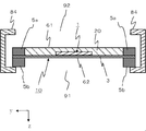
- 13 is a cross-sectional view taken along the line EE ′ of FIG.
- 14 is a cross-sectional view taken along the line FF ′ of FIG.
- acoustic generator of the third example of the above-described embodiment Only differences from the acoustic generator of the third example of the above-described embodiment will be described, and the same components will be denoted by the same reference numerals, and redundant description will be omitted.
- the sound generator of this example includes a shield 84 instead of the shields 83a and 83b in the sound generator of the third example of the embodiment.
- the shield 84 has a different shape from the shields 83a and 83b.
- the shield 84 has a rectangular parallelepiped box-like shape in which one opening is formed in each of the central portions of two surfaces opposed to each other in the z-axis direction in the figure.
- the shield 84 has accommodated the frame members 5a and 5b and the vibration part 10 inside.
- the first opening 91 located in the + z direction in the figure has substantially the same size as the frame member 5 b, and the frame member 5 b is bonded and fixed to the periphery of the first opening 91.
- the entire second surface 62 of the vibration unit 10 is exposed to the external space through the first opening 91 of the shield 84.
- the second opening 92 located in the ⁇ z direction in the figure is made smaller than the first opening 91, and the central part in the length direction (the x-axis direction in the figure) of the first surface 61 of the vibration part 10. Is exposed to the external space through the second opening 92 over the entire width direction (the y-axis direction in the figure), that is, the shield 84 is a length of the first surface 61 of the vibration unit 10.
- Both ends in the direction (x-axis direction in the figure) are shielded against the external space over the entire width direction (y-axis direction in the figure), and among the first surface 61 of the vibration part 10 A portion that is not shielded by the shield 84 is exposed to the external space.
- the acoustic generator of this example sets the area of the 1st part 74a (part given the dot of Drawing 12) which is a part exposed to external space in the 1st surface 61 of vibration part 10 as S1, Assuming that the area of the second portion 74b (the portion with the dots in FIG. 11) exposed to the external space on the second surface 62 of the vibration unit 10 is S2, 0 ⁇ S1 ⁇ S2. Has been. Thereby, similarly to the sound generator of the third example of the above-described embodiment, it is possible to generate sound with good sound quality.
- the shield 84 has both ends in the length direction (x-axis direction in the figure) on the first surface 61 of the vibration part 10 in the width direction (y-axis direction in the figure). And the part of the first surface 61 of the vibration unit 10 that is not shielded by the shield 84 is exposed to the external space. This can further reduce the wraparound of the sound generated from the first surface 61 of the vibration unit 10 to the external space on the second surface 62 side at a particularly low frequency, as well as an air spring, unnecessary resonance, etc. It is possible to further reduce the deterioration of the sound quality due to.
- FIG. 15 is a block diagram illustrating an example of the configuration of the electronic device 50 according to the fifth example of the embodiment of this invention.
- the electronic device 50 of this example includes an acoustic generator 30, an electronic circuit 60, a key input unit 50c, a microphone input unit 50d, a display unit 50e, and an antenna 50f.
- FIG. 15 is a block diagram assuming an electronic device such as a mobile phone, a tablet terminal, or a personal computer.
- the electronic circuit 60 includes a control circuit 50a and a communication circuit 50b.
- the electronic circuit 60 is connected to the sound generator 30 and has a function of outputting an audio signal to the sound generator.
- the control circuit 50 a is a control unit of the electronic device 50.
- the communication circuit 50b transmits and receives data through the antenna 50f based on the control of the control circuit 50a.
- the key input unit 50c is an input device of the electronic device 50 and accepts a key input operation by an operator.
- the microphone input unit 50d is also an input device of the electronic device 50, and accepts a voice input operation by an operator.
- the display unit 50e is a display output device of the electronic device 50, and outputs display information based on the control of the control circuit 50a.
- the sound generator 30 is a sound generator as in the first to fourth examples of the embodiment described above.
- the sound generator 30 functions as a sound output device in the electronic device 50, and generates sound (including sound outside the audible frequency band) based on the sound signal input from the electronic circuit 60.
- the sound generator 30 is connected to the control circuit 50a of the electronic circuit 60, and generates sound upon receiving application of a voltage controlled by the control circuit 50a.
- the electronic apparatus 50 of this example Since the electronic apparatus 50 of this example generates sound using the sound generator 30 as in the first to fourth examples of the above-described embodiment, it generates sound with high sound pressure in a wide frequency range. be able to.
- the electronic circuit 60, the key input unit 50c, the microphone input unit 50d, the display unit 50e, and the antenna shown in FIG. 50f and the sound generator 30 can be provided.
- the sound generator shield 84 shown in FIGS. 11 to 14 is also used as a housing of the electronic device, and the electronic device shown in FIG.
- the circuit 60, the key input unit 50c, the microphone input unit 50d, the display unit 50e, and the antenna 50f can be provided.
- a key input unit 50c a microphone input unit 50d, a display unit 50e, and an antenna 50f are provided in a housing.
- the device main body and the sound generators shown in the first to fourth examples of the embodiment can be electrically connected via a cable wire, a lead wire, or the like.
- the electronic device of this example does not need to have all the key input part 50c, the microphone input part 50d, the display part 50e, and the antenna 50f shown in FIG. And at least the electronic circuit 60.
- the electronic device may have other components.
- the electronic circuit 60 is not limited to the electronic circuit 60 having the above-described configuration, and may be an electronic circuit having another configuration.
- the electronic device of this example is not limited to the above-described electronic devices such as a mobile phone, a tablet terminal, and a personal computer.
- electronic devices having a function of generating sound and sound such as a television, an audio device, a radio, a vacuum cleaner, a washing machine, a refrigerator, and a microwave oven, as in the first to fourth examples of the above-described embodiment
- the sound generator 30 can be used as a sound generator.
- the sound generator 30 is configured such that at least a part of both the first surface 61 and the second surface 62 of the vibrating unit 10 is an external space (a target for listening to sound generated by the sound generator). It is necessary to be exposed to the space where there is. Therefore, even when the acoustic generator 30 is accommodated in the casing of the electronic device, the acoustic generator 30 is not completely covered by the casing of the electronic device, but the vibrating portion 10 of the acoustic generator 30 is not provided. At least a part of both of the first surface 61 and the second surface 62 is exposed to the external space (not the space inside the electronic device, but the space in which the sound generated by the sound generator is present). It is necessary to do so.
- a diaphragm is not limited to a film.
- a plate-like object formed of metal, ceramics, synthetic resin, or the like may be used, or a film-like object made of various rubber materials may be used.
- the present invention is not limited to this.
- the resin layer 20 may not be formed. That is, the vibration part 10 should just contain the exciter 1 and a diaphragm at least.
- the exciter 1 only needs to have a function of converting an electric signal into mechanical vibration, and another apparatus having a function of converting an electric signal into mechanical vibration may be used as the exciter 1.
- an electrodynamic exciter, an electrostatic exciter, or an electromagnetic exciter well known as an exciter for vibrating a speaker may be used as the exciter 1.
- the electrodynamic exciter is such that an electric current is passed through a coil disposed between the magnetic poles of a permanent magnet to vibrate the coil.
- the electrostatic exciter is composed of two metals facing each other. A bias and an electric signal are passed through the plate to vibrate the metal plate, and an electromagnetic exciter is an electric signal that is passed through the coil to vibrate a thin iron plate.
- Exciter 10 Vibrating unit 30: Sound generator 50: Electronic device 60: Electronic circuit 61: First surface 62: Second surfaces 71a, 72a, 73a, 74a: First portions 71b, 72b, 73b, 74b: second parts 81a, 81b, 82a, 82b, 83a, 83b, 84: shield 91: first opening 92: second opening
Abstract
[Problem] To provide an acoustic generator capable of generating sound of better sound quality, and an electronic apparatus in which same is used. [Solution] The acoustic generator has at least: an oscillation unit (10) which includes an exciter (1) which oscillates on input of an electrical signal, and a diaphragm which the exciter (1) is attached to and which oscillates together with the exciter (1); and shields (81a and 81b) which are spaced apart from the oscillation unit (10) and shield a portion of a first surface (61) from the external space, said first surface (61) being one main surface of the oscillation unit (10). In the acoustic generator, 0 < S1 < S2 is satisfied, where S1 is the area of a first portion (71a), which is an external-space-exposed portion of the first surface (61) of the oscillation unit (10), and S2 is the area of a second portion (71b), which is an external-space-exposed portion of a second surface (62), which is the other main surface of the oscillation unit (10).
Description
本発明は、音響発生器およびそれを用いた電子機器に関するものである。
The present invention relates to an acoustic generator and an electronic device using the same.
従来、振動板に圧電素子を取り付けたスピーカーが知られている(例えば、特許文献1を参照。)。
Conventionally, a speaker in which a piezoelectric element is attached to a diaphragm is known (for example, see Patent Document 1).
しかしながら、上述した従来のスピーカーは、振動板の裏面から生じる逆位相の音が表側に回り込むことにより、振動板の表側において特に低音が小さくなって音質が劣化するという問題があった。また、振動板の裏面から生じる逆位相の音の表側への回り込みを防止するためにバッフルボードを設置すると、音響発生器が大型化してしまうという問題があった。
However, the above-described conventional speaker has a problem in that the sound quality deteriorates due to particularly low-pitched sound on the front side of the diaphragm due to the reverse phase sound generated from the back surface of the diaphragm. Further, when a baffle board is installed to prevent the reverse phase sound generated from the back surface of the diaphragm from entering the front side, there is a problem that the sound generator is increased in size.
本発明はこのような従来の技術における問題点に鑑みて案出されたものであり、その目的は、良好な音質の音を発生させることができる音響発生器およびそれを用いた電子機器を提供することにある。
The present invention has been devised in view of such problems in the prior art, and an object thereof is to provide an acoustic generator capable of generating sound of good sound quality and an electronic device using the same. There is to do.
本発明の音響発生器は、外部空間に音響を放射するための音響発生器であって、電気信号が入力されて振動する励振器および該励振器が取り付けられて該励振器とともに振動する振動板を含む振動部と、該振動部と間隔をあけて配置されて該振動部の一方主面である第1の面の一部を前記外部空間に対して遮蔽する遮蔽体とを少なくとも有しており、前記振動部の前記第1の面における前記外部空間に対して露出する部分である第1部分の面積をS1とし、前記振動部の他方主面である第2の面における前記外部空間に対して露出する部分である第2部分の面積をS2とすると、0<S1<S2であることを特徴とするものである。
The sound generator of the present invention is a sound generator for radiating sound to an external space, and an exciter that vibrates when an electric signal is inputted thereto, and a vibration plate that is attached with the exciter and vibrates together with the exciter And at least a shielding body that is disposed at a distance from the vibrating portion and shields a part of the first surface that is one main surface of the vibrating portion from the external space. The area of the first portion, which is the portion exposed to the external space on the first surface of the vibrating portion, is S1, and the external space on the second surface that is the other main surface of the vibrating portion is On the other hand, when the area of the second portion, which is the exposed portion, is S2, 0 <S1 <S2.
本発明の電子機器は、前記音響発生器と、該音響発生器に接続された電子回路とを少なくとも有しており、前記音響発生器から音響を発生させる機能を有することを特徴とするものである。
The electronic device of the present invention includes at least the sound generator and an electronic circuit connected to the sound generator, and has a function of generating sound from the sound generator. is there.
本発明の音響発生器によれば、良好な音質の音を発生させることができる音響発生器を得ることができる。本発明の電子機器によれば、良好な音質の音を発生させることができる電子機器を得ることができる。
According to the sound generator of the present invention, it is possible to obtain a sound generator that can generate sound of good sound quality. According to the electronic device of the present invention, it is possible to obtain an electronic device capable of generating sound with good sound quality.
以下、本発明の実施の形態の例である音響発生器およびそれを用いた電子機器を添付の図面を参照しつつ詳細に説明する。
Hereinafter, an acoustic generator which is an example of an embodiment of the present invention and an electronic device using the same will be described in detail with reference to the accompanying drawings.
(実施の形態の第1の例)
図1,図2は本発明の実施の形態の第1の例の音響発生器を模式的に示す平面図である。図3は図2におけるA-A’線断面図である。 (First example of embodiment)
1 and 2 are plan views schematically showing a sound generator of a first example of an embodiment of the present invention. 3 is a cross-sectional view taken along line AA ′ in FIG.
図1,図2は本発明の実施の形態の第1の例の音響発生器を模式的に示す平面図である。図3は図2におけるA-A’線断面図である。 (First example of embodiment)
1 and 2 are plan views schematically showing a sound generator of a first example of an embodiment of the present invention. 3 is a cross-sectional view taken along line AA ′ in FIG.
本例の音響発生器は、図1~図3に示すように、励振器1と、フィルム3と、枠部材5a、5bと、樹脂層20と、遮蔽体81a,81bとを有している。
As shown in FIGS. 1 to 3, the sound generator of this example includes an exciter 1, a film 3, frame members 5a and 5b, a resin layer 20, and shields 81a and 81b. .
枠部材5a,5bは、矩形の枠状の形状を有している。枠部材5a、5b間にはフィルム3の外周部が挟み込まれ、フィルム3に張力を加えた状態で固定している。枠部材5a、5bの材質および形状は特に限定されるものではなく、フィルム3および樹脂層20よりも変形し難いものであれば良い。例えば、硬質樹脂、プラスチック、エンジニアリングプラスチック、セラミックス、金属等を用いて枠部材5a、5bを形成することができる。例えば、厚み100~1000μmのステンレス製のものを好適に用いることができる。また、枠部材5a、5bの内形状も、矩形状に限定されるものではなく、楕円形や菱形であってもよい。なお、枠部材5bは必須ではなく、枠部材5bを有さない場合には、例えば、枠部材5aの+z方向の表面にフィルム3を接着すればよい。
The frame members 5a and 5b have a rectangular frame shape. The outer periphery of the film 3 is sandwiched between the frame members 5a and 5b, and the film 3 is fixed in a tensioned state. The material and shape of the frame members 5a and 5b are not particularly limited as long as they are more difficult to deform than the film 3 and the resin layer 20. For example, the frame members 5a and 5b can be formed using hard resin, plastic, engineering plastic, ceramics, metal, or the like. For example, a stainless steel material having a thickness of 100 to 1000 μm can be preferably used. Further, the inner shape of the frame members 5a and 5b is not limited to a rectangular shape, and may be an ellipse or a rhombus. In addition, the frame member 5b is not essential, and when the frame member 5b is not provided, for example, the film 3 may be bonded to the surface in the + z direction of the frame member 5a.
フィルム3は、面方向に張力をかけられた状態で、矩形状の周縁部を全体的に枠部材5a、5bで挟持されて固定されており、枠部材5a、5bによって振動可能に支持されている。すなわち、フィルム3における枠部材5a、5bの内側に位置する振動可能な部分が、励振器1が取り付けられて励振器1とともに振動する振動板として機能している。フィルム3の厚みは、例えば、10~200μmとされる。フィルム3は、例えば、ポリエチレン、ポリイミド、ポリプロピレン、ポリスチレン等の樹脂を用いて形成することができる。パルプや繊維等からなる紙によってフィルム3を構成しても構わない。
The film 3 is fixed in such a manner that the peripheral edge of the rectangular shape is sandwiched and fixed by the frame members 5a and 5b as a whole in a state where tension is applied in the plane direction, and is supported by the frame members 5a and 5b so as to vibrate. Yes. That is, the vibrable portion located inside the frame members 5 a and 5 b in the film 3 functions as a diaphragm that is attached with the exciter 1 and vibrates together with the exciter 1. The thickness of the film 3 is, for example, 10 to 200 μm. The film 3 can be formed using resin, such as polyethylene, a polyimide, a polypropylene, a polystyrene, for example. The film 3 may be made of paper made of pulp, fiber, or the like.
励振器1は、上下の主面(図のz軸方向の両端面)が矩形である板状の形状を有する圧電素子である。詳細な図示を省略するが、励振器1は、圧電セラミックスからなる圧電体層と内部電極層とを交互に積層してなる積層体と、この積層体の上下面(図のz軸方向の両端面)に形成された表面電極層と、積層体の長手方向(図のx軸方向)の両端面にそれぞれ設けられた一対の端子電極とで構成されている。なお、表面電極および内部電極層は、積層体の長手方向(図のx軸方向)の両端面に交互に引き出されており、それぞれ端子電極に接続されている。そして、図示せぬ配線を介して一対の端子電極に電気信号が加えられる。
The exciter 1 is a piezoelectric element having a plate shape whose upper and lower main surfaces (both end surfaces in the z-axis direction in the figure) are rectangular. Although not shown in detail, the exciter 1 includes a laminate in which piezoelectric layers made of piezoelectric ceramics and internal electrode layers are alternately laminated, and upper and lower surfaces of the laminate (both ends in the z-axis direction in the figure). Surface electrode layer and a pair of terminal electrodes provided on both end faces in the longitudinal direction (x-axis direction in the figure) of the laminate. In addition, the surface electrode and the internal electrode layer are alternately drawn to both end faces in the longitudinal direction (x-axis direction in the drawing) of the multilayer body, and are connected to the terminal electrodes, respectively. Then, an electrical signal is applied to the pair of terminal electrodes via a wiring (not shown).
励振器1は、バイモルフ型の圧電素子とされており、電気信号が入力されたときに、任意の瞬間において、厚み方向(図のz軸方向)における一方側と他方側とで伸縮が逆になるようにされている。よって、励振器1は、電気信号が入力されて図のz軸方向に屈曲振動する。そして、励振器1のフィルム3側の主面とフィルム3とは、例えば、エポキシ系樹脂、シリコン系樹脂、ポリエステル系樹脂等の既知の接着剤や両面テープ等によって接着されている。よって、電気信号が入力されて励振器1が振動すると、フィルム3の枠部材5a、5bの内側の部分で構成される振動板も、励振器1とともに振動する。なお、励振器1として、例えば、電気信号が入力されて伸縮振動する圧電素子と金属板とを張り合わせて構成したモノモルフ型の振動素子を用いても構わない。
The exciter 1 is a bimorph type piezoelectric element. When an electric signal is input, expansion and contraction are reversed between one side and the other side in the thickness direction (z-axis direction in the figure) at an arbitrary moment. It is supposed to be. Thus, the exciter 1 receives an electric signal and bends and vibrates in the z-axis direction in the figure. The main surface of the exciter 1 on the film 3 side and the film 3 are bonded to each other with a known adhesive such as an epoxy resin, a silicon resin, or a polyester resin, or a double-sided tape. Therefore, when the electric signal is input and the exciter 1 vibrates, the diaphragm formed by the inner portions of the frame members 5 a and 5 b of the film 3 also vibrates together with the exciter 1. As the exciter 1, for example, a monomorph type vibration element configured by bonding a piezoelectric element that receives an electric signal to expand and contract and vibrates and a metal plate may be used.
励振器1の圧電体層としては、ジルコン酸鉛(PZ)、チタン酸ジルコン酸鉛(PZT)、Bi層状化合物、タングステンブロンズ構造化合物等の非鉛系圧電体材料等、従来用いられている圧電セラミックスを用いることができる。圧電体層の1層の厚みは、低電圧駆動という観点から、10~100μm程度とするのが望ましい。大きな屈曲撓み振動を誘起させ音圧を高めるために、圧電体層の圧電d31定数が180pm/V以上であることが望ましい。
Piezoelectric layers of the exciter 1 include piezoelectric materials conventionally used such as lead-free piezoelectric materials such as lead zirconate (PZ), lead zirconate titanate (PZT), Bi layered compounds, and tungsten bronze structure compounds. Ceramics can be used. The thickness of one piezoelectric layer is desirably about 10 to 100 μm from the viewpoint of low voltage driving. In order to induce a large flexural flexural vibration and increase the sound pressure, the piezoelectric d31 constant of the piezoelectric layer is preferably 180 pm / V or more.
励振器1の内部電極層としては、既知の種々の金属材料を用いることができる。例えば、銀とパラジウムとからなる金属成分と圧電体層を構成する材料成分とを含有する内部電極層とすると、圧電体層と内部電極層との熱膨張差による応力を低減することができるが、他の材料を用いて形成しても構わない。励振器1の表面電極層および端子電極は、既知の種々の金属材料を用いて形成することができる。例えば、銀からなる金属成分およびガラス成分を含有する材料を用いて形成すると、圧電体層や内部電極層と、表面電極層や端子電極との密着性を高めることができるが、他の材料を用いて形成しても構わない。
As the internal electrode layer of the exciter 1, various known metal materials can be used. For example, when an internal electrode layer containing a metal component composed of silver and palladium and a material component constituting the piezoelectric layer is used, stress due to a difference in thermal expansion between the piezoelectric layer and the internal electrode layer can be reduced. Alternatively, other materials may be used. The surface electrode layer and the terminal electrode of the exciter 1 can be formed using various known metal materials. For example, when a material containing a silver metal component and a glass component is used, adhesion between the piezoelectric layer and internal electrode layer and the surface electrode layer and terminal electrode can be improved. May be used.
樹脂層20は、励振器1を埋設するように、枠部材5aの内側の全体に渡って充填されている。樹脂層20は、既知の種々の材料を用いて形成することができる。例えば、アクリル系樹脂、シリコン系樹脂等の樹脂や、あるいはゴム等を用いることができ、例えば、ヤング率が1MPa~1GPaの範囲にあるものが望ましい。また、樹脂層20の厚みは、スプリアスを抑制するという点から、励振器1を完全に覆う程度の厚みであることが望ましい。
The resin layer 20 is filled over the entire inside of the frame member 5a so that the exciter 1 is embedded. The resin layer 20 can be formed using various known materials. For example, a resin such as an acrylic resin or a silicon resin, rubber, or the like can be used. For example, a material having a Young's modulus in the range of 1 MPa to 1 GPa is desirable. Further, the thickness of the resin layer 20 is desirably a thickness that completely covers the exciter 1 from the viewpoint of suppressing spurious.
本例の振動装置では、フィルム3における枠部材5a、5bの内側に位置する振動可能な部分で構成される振動板と、その上に配置された励振器1および樹脂層20とが、一体的に形成されて、一体となって振動可能になっている。そして、この枠部材5a、5bより内側の振動可能な部分全体によって振動部10が構成されている。すなわち、振動部10は、振動板と、振動板に取り付けられた励振器1と、樹脂層20とを含んでいる。そして、振動部10は、一体となって振動して音響を発生させる部分である。振動部10は、扁平状であり、長さ方向(図のx軸方向)と、幅方向(図のy軸方向)と、厚み方向(図のz軸方向)とを有している。また、振動部10は、矩形状の周縁が全体的に枠部材5a、5bによって支持されている。そして、振動部10は、励振器1の振動によって励振器1とともに振動し、音響を発生させる。
In the vibration device of this example, the diaphragm configured by the vibrable portion located inside the frame members 5a and 5b in the film 3, and the exciter 1 and the resin layer 20 disposed thereon are integrally formed. And can be vibrated together. And the vibration part 10 is comprised by the whole part which can vibrate inside these frame members 5a and 5b. That is, the vibration unit 10 includes a vibration plate, the exciter 1 attached to the vibration plate, and the resin layer 20. And the vibration part 10 is a part which vibrates integrally and generates a sound. The vibration part 10 is flat and has a length direction (x-axis direction in the figure), a width direction (y-axis direction in the figure), and a thickness direction (z-axis direction in the figure). Further, the vibrating portion 10 has a rectangular peripheral edge supported entirely by the frame members 5a and 5b. And the vibration part 10 vibrates with the exciter 1 by the vibration of the exciter 1, and generates a sound.
遮蔽体81a,81bは、各々略L字型の形状を有しており、一方端部(図の+z方向の端部)が枠部材5aに接合されて固定されているとともに、他方端部側が枠部材5aの枠の内側へ向かって張り出している。そして、その張り出した部分が、振動部10の一部分と間隔をあけて対向するように配置されている。そして、遮蔽体81a,81bにおける振動部10と間隔をあけて対向する部分が、振動部10の一方主面(図の-z方向の主面)である第1の面61の一部(遮蔽体81a,81bと対向する部分)を外部空間に対して遮蔽している。すなわち、遮蔽体81a,81bは、振動部10と間隔をあけて配置されており、振動部10の一方主面である第1の面61の一部を外部空間に対して遮蔽している。なお、「振動部10の第1の面61上の1つの点(任意の点であり、以下、P点と称する)を外部空間に対して遮蔽する」とは、P点における第1の面61の法線上に位置する外部空間中の点から、P点が見えないように隠すことを意味する。また、「振動部10の第1の面61上の1つの点(任意の点であり、以下、Q点と称する)が外部空間に露出している」とは、Q点における第1の面61の法線上に位置する外部空間中の点から、Q点が見えていることを意味する。よって、「第1の面61における外部空間に露出した部分」とは、「第1の面61上の部分であり、その部分に含まれる全ての点が外部空間に露出している部分」を意味する。また、外部空間とは、音響発生器よりも外側の空間であり、音響発生器が発生する音響を聞かせる対象が存在する空間を意味する。また、遮蔽体81a,81bは、振動部10の第1の面61と間隔を開けて配置されて、振動部10の第1の面61を外部空間から遮蔽するものである。振動部10の第1の面61または第2の面62に接合されて振動部10とともに振動するものは、遮蔽体81a,81bではなく、振動部10の一部と見なされる。なお、遮蔽体81a,81bは、振動部10の第1の面61に垂直な方向において、振動部10の第1の面61と間隔を開けて配置されていればよく、振動部10の第1の面61の面内方向において、遮蔽体81a,81bの端部が振動部10の第1の面61の端部に接触していても構わない。
Each of the shields 81a and 81b has a substantially L-shape, and one end (the end in the + z direction in the figure) is joined and fixed to the frame member 5a, and the other end side is Projecting toward the inside of the frame of the frame member 5a. The protruding portion is disposed so as to face a part of the vibrating portion 10 with a gap. A portion of the shields 81a and 81b that faces the vibrating portion 10 with a space therebetween is a part of the first surface 61 (shielding) that is one main surface (the main surface in the −z direction in the drawing) of the vibrating portion 10. The portions facing the bodies 81a and 81b) are shielded from the external space. In other words, the shields 81a and 81b are arranged at a distance from the vibrating unit 10 and shield a part of the first surface 61 that is one main surface of the vibrating unit 10 from the external space. Note that “shielding one point (arbitrary point, hereinafter referred to as P point) on the first surface 61 of the vibration unit 10 from the external space” means the first surface at the P point. This means that the point P is hidden from the point in the external space located on the normal line 61 so that it cannot be seen. Further, “one point on the first surface 61 of the vibrating portion 10 (which is an arbitrary point, hereinafter referred to as Q point) is exposed to the external space” means that the first surface at the Q point It means that the point Q is visible from the point in the external space located on the normal line 61. Therefore, “the portion of the first surface 61 exposed to the external space” means “the portion of the first surface 61 on which all points included in the portion are exposed to the external space”. means. In addition, the external space is a space outside the sound generator, and means a space where there is a target for listening to the sound generated by the sound generator. Further, the shields 81a and 81b are arranged at a distance from the first surface 61 of the vibration unit 10, and shield the first surface 61 of the vibration unit 10 from the external space. What is joined to the first surface 61 or the second surface 62 of the vibration unit 10 and vibrates with the vibration unit 10 is regarded as a part of the vibration unit 10, not the shields 81 a and 81 b. The shields 81a and 81b only need to be spaced apart from the first surface 61 of the vibration unit 10 in the direction perpendicular to the first surface 61 of the vibration unit 10. The end portions of the shields 81 a and 81 b may be in contact with the end portion of the first surface 61 of the vibration unit 10 in the in-plane direction of the first surface 61.
また、遮蔽体81bは、振動部10の第1の面61における長さ方向(図のx軸方向)の一方端部(+x方向側の端部)を外部空間に対して遮蔽しており、遮蔽体81aは、振動部10の第1の面61における長さ方向の他方端部(-x方向側の端部)を外部空間に対して遮蔽している。そして、遮蔽体81a,81bは、振動部10の第1の面61における幅方向(図のy軸方向)の中央部付近を外部空間に対して遮蔽している。
Further, the shield 81b shields one end (the end on the + x direction side) in the length direction (x-axis direction in the drawing) of the first surface 61 of the vibration unit 10 from the external space, The shield 81a shields the other end in the length direction (the end on the −x direction side) of the first surface 61 of the vibration unit 10 from the external space. The shields 81a and 81b shield the vicinity of the central portion in the width direction (y-axis direction in the drawing) of the first surface 61 of the vibration unit 10 from the external space.
このような遮蔽体81a,81bは、例えば、合成樹脂,木材,金属,セラミックス等の種々の材料を用いて形成することができる。遮蔽体81a,81bの形状も特に限定されるものではなく、種々の形状にすることが可能である。遮蔽体81a,81bの厚みも、特に限定されるものではなく、例えば、1mm~10mm程度に設定される。なお、振動部10の他方主面である第2の面62は、全体が外部空間に対して露出されている。
Such shields 81a and 81b can be formed using various materials such as synthetic resin, wood, metal and ceramics. The shapes of the shields 81a and 81b are not particularly limited, and can be various shapes. The thicknesses of the shields 81a and 81b are not particularly limited, and are set to about 1 mm to 10 mm, for example. In addition, the 2nd surface 62 which is the other main surface of the vibration part 10 is entirely exposed with respect to external space.
このように、本例の音響発生器は、振動部10の一方主面である第1の面61の一部を外部空間に対して遮蔽する遮蔽体81a,81bを有しているとともに、振動部10の第1の面61における外部空間に対して露出する部分である第1部分71a(図2のドットを付した部分)の面積をS1とし、振動部10の他方主面である第2の面62における外部空間に対して露出する部分である第2部分71b(図1のドットを付した部分)の面積をS2とすると、0<S1<S2となるようにされている。これにより、振動部10の第1の面61から発生する音の第2の面62側の外部空間への回り込みを低減できるので、良好な音質の音を発生させることができる音響発生器を得ることができる。また、第1の面61側に密閉空間を形成しないので、空気バネや不要な共振等による音質の悪化を防止することができる。
As described above, the sound generator of the present example includes the shields 81a and 81b that shield a part of the first surface 61, which is one main surface of the vibration unit 10, from the external space, and vibrates. The area of the first portion 71a (the portion with the dots in FIG. 2) exposed to the external space in the first surface 61 of the portion 10 is S1, and the second main surface of the vibrating portion 10 is the second main surface. If the area of the second portion 71b (the portion marked with dots in FIG. 1) exposed to the external space on the surface 62 is S2, 0 <S1 <S2. Thereby, since the wraparound of the sound generated from the first surface 61 of the vibration unit 10 to the external space on the second surface 62 side can be reduced, an acoustic generator capable of generating sound with good sound quality is obtained. be able to. Further, since the sealed space is not formed on the first surface 61 side, it is possible to prevent deterioration of sound quality due to an air spring, unnecessary resonance, or the like.
また、本例の音響発生器は、振動部10の第1の面61の中央部および第2の面62の中央部の両方が外部空間に対して露出していることから、空気バネや不要な共振等による音質の悪化をさらに低減することができる。この効果が得られる理由は、振動部10の第1の面61および第2の面62の中央部が、振動部10の最も低い共振周波数を含む複数の共振周波数において最も振幅が大きくなる位置であるためではないかと考えられる。なお、第1の面61の中央部とは、第1の面61の中央に位置する部分である。より詳細には、第1の面61の重心を中心とする部分であり、第1の面61の面積の10%の面積を有する部分である。同様に、第2の面62の中央部とは、第2の面62の中央に位置する部分である。より詳細には、第2の面62の重心を中心とする部分であり、第2の面62の面積の10%の面積を有する部分である。
Moreover, since the sound generator of this example has both the center part of the 1st surface 61 of the vibration part 10 and the center part of the 2nd surface 62 exposed with respect to external space, an air spring and unnecessary It is possible to further reduce the deterioration of sound quality due to the resonance. The reason why this effect is obtained is that the central portion of the first surface 61 and the second surface 62 of the vibration unit 10 has the largest amplitude at a plurality of resonance frequencies including the lowest resonance frequency of the vibration unit 10. It is thought that it is because there is. The central portion of the first surface 61 is a portion located at the center of the first surface 61. More specifically, it is a portion centered on the center of gravity of the first surface 61 and is a portion having an area of 10% of the area of the first surface 61. Similarly, the central portion of the second surface 62 is a portion located at the center of the second surface 62. More specifically, it is a portion centered on the center of gravity of the second surface 62 and a portion having an area of 10% of the area of the second surface 62.
振動部10の第2の面62は、外部空間に露出する部分71bの割合が大きいことが望ましく、振動部10の第2の面62全体が外部空間に露出していることが望ましい。振動部10の第1の面61における外部空間に露出する部分71aの割合は、振動部10の第1の面61から発生する音の第2の面62側の外部空間への回り込みを低減したい程度に応じて適宜設定することができる。空気バネや不要な共振等による音質の悪化を低減するという観点では、振動部10の第1の面61の1/3以上が外部空間に露出するようにするのが望ましく、振動部10の第1の面61の半分以上が外部空間に露出するようにするのが更に望ましい。
The second surface 62 of the vibration part 10 desirably has a large proportion of the portion 71b exposed to the external space, and the entire second surface 62 of the vibration part 10 is desirably exposed to the external space. The ratio of the portion 71a exposed to the external space in the first surface 61 of the vibration unit 10 is to reduce the wraparound of the sound generated from the first surface 61 of the vibration unit 10 into the external space on the second surface 62 side. It can set suitably according to a grade. From the viewpoint of reducing deterioration in sound quality due to an air spring, unnecessary resonance, or the like, it is desirable that 1/3 or more of the first surface 61 of the vibration unit 10 be exposed to the external space. It is further desirable that more than half of one surface 61 is exposed to the external space.
本例の音響発生器は、例えば次のようにして製造することができる。まず、圧電材料の粉末にバインダー、分散剤、可塑剤、溶剤を添加して掻き混ぜて、スラリーを作製する。圧電材料としては、鉛系、非鉛系のうちいずれでも使用することができる。次に、得られたスラリーをシート状に成形し、グリーンシートを作製する。このグリーンシートに導体ペーストを印刷して内部電極となる導体パターンを形成し、この導体パターンが形成されたグリーンシートを積層して、積層成形体を作製する。
The sound generator of this example can be manufactured as follows, for example. First, a binder, a dispersant, a plasticizer, and a solvent are added to the powder of the piezoelectric material and stirred to prepare a slurry. As the piezoelectric material, any of lead-based and non-lead-based materials can be used. Next, the obtained slurry is formed into a sheet shape to produce a green sheet. A conductor paste is printed on the green sheet to form a conductor pattern to be an internal electrode, and the green sheet on which the conductor pattern is formed is laminated to produce a laminated molded body.
次に、この積層成形体を脱脂、焼成し、所定寸法にカットすることにより積層体を得ることができる。必要に応じて、積層体の外周部を加工する。次に、積層体の積層方向の主面に、導体ペーストを印刷して表面電極層となる導体パターンを形成し、積層体の長手方向(図のx軸方向)の両側面に、導体ペーストを印刷して一対の端子電極となる導体パターンを形成する。そして、所定の温度で電極の焼付けを行うことにより、励振器1となる構造体を得ることができる。その後に、励振器1に圧電性を付与するために表面電極層または一対の端子電極を通じて直流電圧を印加して、励振器1の圧電体層の分極を行う。このようにして励振器1を得ることができる。
Next, the laminated body can be obtained by degreasing, firing, and cutting into a predetermined dimension. If necessary, the outer periphery of the laminate is processed. Next, a conductor paste is printed on the main surface in the stacking direction of the laminate to form a conductor pattern to be a surface electrode layer, and the conductor paste is applied to both side surfaces in the longitudinal direction (x-axis direction in the figure) of the laminate. A conductor pattern to be printed is formed to be a pair of terminal electrodes. And the structure used as the exciter 1 can be obtained by baking an electrode at predetermined temperature. Thereafter, in order to impart piezoelectricity to the exciter 1, a DC voltage is applied through the surface electrode layer or the pair of terminal electrodes to polarize the piezoelectric layer of the exciter 1. In this way, the exciter 1 can be obtained.
次に、フィルム3を準備し、フィルム3に張力をかけた状態で、フィルム3の周縁部を枠部材5a、5bで挟んで固定する。次に、フィルム3の表面に励振器1を接着剤等により接合し、励振器1に配線を接続する。そして、枠部材5a、5bの内側に樹脂を流し込んで硬化させることにより樹脂層20を形成する。そして、枠部材5aに、所定形状に加工した遮蔽体81a,81bを接着剤等で接合する。このようにして、本例の音響発生器を得ることができる。
Next, the film 3 is prepared, and in a state in which the film 3 is tensioned, the peripheral portion of the film 3 is sandwiched and fixed by the frame members 5a and 5b. Next, the exciter 1 is joined to the surface of the film 3 with an adhesive or the like, and wiring is connected to the exciter 1. And resin layer 20 is formed by pouring resin inside frame members 5a and 5b, and making it harden. Then, the shields 81a and 81b processed into a predetermined shape are joined to the frame member 5a with an adhesive or the like. In this way, the sound generator of this example can be obtained.
(実施の形態の第2の例)
図4,図5は、本発明の実施の形態の第2の例の音響発生器を模式的に示す平面図である。図6は、図5のB-B’線断面図である。なお、本例においては、前述した実施の形態の第1の例の音響発生器と異なる点のみについて説明し、同様の構成要素には同一の参照符号を付して重複する説明を省略する。 (Second example of embodiment)
4 and 5 are plan views schematically showing a second example of the sound generator according to the embodiment of the present invention. 6 is a cross-sectional view taken along line BB ′ of FIG. In this example, only differences from the acoustic generator of the first example of the above-described embodiment will be described, and the same components are denoted by the same reference numerals, and redundant description will be omitted.
図4~図6に示すように、本例の音響発生器は、実施の形態の第1の例の音響発生器における遮蔽体81a,81bに代えて、遮蔽体82a,82bを有している。遮蔽体82a,82bは、形状および配置される位置が、遮蔽体81a,81bと異なっている。遮蔽体82a,82bの各々は、長さ方向の両端部が同一方向に直角に折り曲げられた板状の形状を有している。また、遮蔽体82a,82bの各々は、振動部10の長さ方向(図のx軸方向)の一部分を幅方向(図のy軸方向)に横断するように配置されている。そして、遮蔽体82a,82bは、両端が枠部材5aに接合されて固定され、中央部が振動部10の第1の面61と間隔をあけて対向している。すなわち、遮蔽体82a,82bは、振動部10の第1の面61における長さ方向(図のx軸方向)の一部を、幅方向(図のy軸方向)の全体に渡って外部空間に対して遮蔽している。そして、振動部10の第1の面61のうち、遮蔽体82a,82bで遮蔽されていない部分が、外部空間に対して露出している。
As shown in FIGS. 4 to 6, the sound generator of this example has shields 82a and 82b instead of the shields 81a and 81b in the sound generator of the first example of the embodiment. . The shields 82a and 82b are different from the shields 81a and 81b in terms of shape and position. Each of the shields 82a and 82b has a plate shape in which both end portions in the length direction are bent at right angles in the same direction. In addition, each of the shields 82a and 82b is disposed so as to cross a part in the length direction (x-axis direction in the drawing) of the vibration unit 10 in the width direction (y-axis direction in the drawing). The shields 82a and 82b are bonded and fixed at both ends to the frame member 5a, and the central part faces the first surface 61 of the vibration part 10 with a gap. That is, the shields 82a and 82b are configured so that a part of the length direction (x-axis direction in the drawing) of the first surface 61 of the vibration unit 10 is external space over the entire width direction (y-axis direction in the drawing). Shield against. And the part which is not shielded by the shielding bodies 82a and 82b among the 1st surface 61 of the vibration part 10 is exposed with respect to external space.
そして、本例の音響発生器は、振動部10の第1の面61における、外部空間に対して露出する部分である第1部分72a(図5のドットを付した部分)の面積をS1とし、振動部10の第2の面62における、外部空間に対して露出する部分である第2部分72b(図4のドットを付した部分)の面積をS2とすると、0<S1<S2となるようにされている。これにより、本例の音響発生器は、前述した実施の形態の第1の例の音響発生器と同様に、良好な音質の音を発生させることができる。
In the acoustic generator of this example, the area of the first portion 72a (the portion with the dots in FIG. 5) that is exposed to the external space on the first surface 61 of the vibration unit 10 is S1. When the area of the second portion 72b (the portion with the dots in FIG. 4) exposed to the external space on the second surface 62 of the vibration unit 10 is S2, 0 <S1 <S2. Has been. Thereby, the sound generator of this example can generate a sound of good sound quality, like the sound generator of the first example of the embodiment described above.
また、本例の音響発生器においては、遮蔽体82a,82bが、振動部10の第1の面61における長さ方向(図のx軸方向)の一部を、幅方向(図のy軸方向)の全体に渡って外部空間に対して遮蔽しており、振動部10の第1の面61のうち遮蔽体82a,82bで遮蔽されていない部分が、外部空間に対して露出している。これにより、特に低い周波数において、振動部10の第1の面61から発生する音が、第2の面62側の外部空間への回り込むことを、効率的に低減することができる。この効果が得られる理由の1つは、振動部10の対角線方向が半波長となる共振や、振動部10の長手方向が半波長となる共振などによって発生する、低い周波数の音のレベルを低下できるためではないかと考えられる。
Further, in the acoustic generator of this example, the shields 82a and 82b have a part in the length direction (x-axis direction in the figure) on the first surface 61 of the vibration unit 10 in the width direction (y-axis in the figure). Direction) and the portion of the first surface 61 of the vibration unit 10 that is not shielded by the shields 82a and 82b is exposed to the external space. . Accordingly, it is possible to efficiently reduce the sound generated from the first surface 61 of the vibration unit 10 from entering the external space on the second surface 62 side at a particularly low frequency. One of the reasons why this effect can be obtained is to reduce the level of low-frequency sound generated by resonance in which the diagonal direction of the vibration unit 10 has a half wavelength or resonance in which the longitudinal direction of the vibration unit 10 has a half wavelength. It is thought to be possible.
(実施の形態の第3の例)
図7,図8は、本発明の実施の形態の第3の例の音響発生器を模式的に示す平面図である。図9は、図8のC-C’線断面図である。図10は、図8のD-D’線断面図である。なお、本例においては、前述した実施の形態の第2の例の音響発生器と異なる点のみについて説明し、同様の構成要素には同一の参照符号を付して重複する説明を省略する。 (Third example of embodiment)
7 and 8 are plan views schematically showing a sound generator of a third example of the embodiment of the present invention. 9 is a cross-sectional view taken along the line CC ′ of FIG. 10 is a cross-sectional view taken along the line DD ′ of FIG. In this example, only differences from the acoustic generator of the second example of the above-described embodiment will be described, and the same components will be denoted by the same reference numerals and redundant description will be omitted.
図7~図10に示すように、本例の音響発生器は、実施の形態の第2の例の音響発生器における遮蔽体82a,82bに代えて、遮蔽体83a,83bを有している。そして、遮蔽体83a,83bの形状および位置が、遮蔽体82a,82bと少し異なっている。遮蔽体83a,83bの各々は、長さ方向の両端部および幅方向の一方端部が同一方向に直角に折り曲げられた板状の形状を有している。また、遮蔽体83bは、振動部10の長さ方向の一方端部(図の+x方向端部)を幅方向(図のy軸方向)に横断するように配置されており、遮蔽体83aは、振動部10の長さ方向の他方端部(図の-x方向端部)を幅方向(図のy軸方向)に横断するように配置されている。そして、遮蔽体83a,83bは、長さ方向の両端および幅方向の一方端部が枠部材5aに接合されて固定されており、その他の部分が振動部10の第1の面61と間隔をあけて対向している。すなわち、遮蔽体83a,83bは、振動部10の第1の面61における長さ方向(図のx軸方向)の両端部を、幅方向(図のy軸方向)の全体に渡って外部空間に対して遮蔽している。そして、振動部10の第1の面61のうち、遮蔽体83a,83bで遮蔽されていない部分が、外部空間に対して露出している。
As shown in FIGS. 7 to 10, the sound generator of the present example has shields 83a and 83b instead of the shields 82a and 82b in the sound generator of the second example of the embodiment. . The shapes and positions of the shields 83a and 83b are slightly different from the shields 82a and 82b. Each of the shields 83a and 83b has a plate-like shape in which both end portions in the length direction and one end portion in the width direction are bent at a right angle in the same direction. The shield 83b is disposed so as to cross one end (the + x direction end in the drawing) in the length direction of the vibration unit 10 in the width direction (the y-axis direction in the drawing). The other end portion (the end portion in the −x direction in the figure) in the length direction of the vibrating portion 10 is arranged so as to cross the width direction (the y-axis direction in the drawing). The shields 83a and 83b have both ends in the length direction and one end in the width direction joined and fixed to the frame member 5a, and the other portions are spaced from the first surface 61 of the vibration unit 10. Open and face each other. That is, the shields 83a and 83b are configured so that both ends in the length direction (x-axis direction in the figure) of the first surface 61 of the vibration unit 10 are external spaces over the entire width direction (y-axis direction in the figure). Shield against. And the part which is not shielded by the shielding bodies 83a and 83b among the 1st surface 61 of the vibration part 10 is exposed with respect to external space.
そして、本例の音響発生器は、振動部10の第1の面61における、外部空間に対して露出する部分である第1部分73a(図8のドットを付した部分)の面積をS1とし、振動部10の第2の面62における、外部空間に対して露出する部分である第2部分73b(図7のドットを付した部分)の面積をS2とすると、0<S1<S2となるようにされている。これにより、前述した実施の形態の第2の例の音響発生器と同様に、良好な音質の音を発生させることができる。
In the acoustic generator of this example, the area of the first portion 73a (the portion with the dots in FIG. 8) that is exposed to the external space on the first surface 61 of the vibration unit 10 is S1. When the area of the second portion 73b (the portion marked with the dots in FIG. 7) that is exposed to the external space in the second surface 62 of the vibration unit 10 is S2, 0 <S1 <S2. Has been. Thereby, similarly to the acoustic generator of the second example of the above-described embodiment, it is possible to generate sound with good sound quality.
そして、本例の音響発生器においては、遮蔽体83a,83bが、振動部10の第1の面61における長さ方向(図のx軸方向)の両端部を、幅方向(図のy軸方向)の全体に渡って外部空間に対して遮蔽しており、振動部10の第1の面61のうち遮蔽体83a,83bで遮蔽されていない部分が、外部空間に対して露出している。これにより、特に低い周波数において、振動部10の第1の面61から発生する音が、第2の面62側の外部空間へ回り込むことを、更に低減することができるとともに、空気バネや不要な共振等による音質の悪化を防止することができる。
In the acoustic generator of the present example, the shields 83a and 83b are configured so that both end portions in the length direction (x-axis direction in the drawing) of the first surface 61 of the vibration unit 10 are arranged in the width direction (y-axis in the drawing). Direction) and the portion of the first surface 61 of the vibration unit 10 that is not shielded by the shields 83a and 83b is exposed to the external space. . As a result, it is possible to further reduce the noise generated from the first surface 61 of the vibration unit 10 from entering the external space on the second surface 62 side at a particularly low frequency, as well as an air spring and unnecessary. Deterioration of sound quality due to resonance or the like can be prevented.
なお、遮蔽体83a,83bが、振動部10の第1の面61における長さ方向(図のx軸方向)の少なくとも一方の端部を、幅方向(図のy軸方向)の全体に渡って外部空間に対して遮蔽しており、振動部10の第1の面61のうち遮蔽体83a,83bで遮蔽されていない部分が、外部空間に対して露出しているようにしても良い。これにより、音の回り込みを低減する効果は小さくなるものの、同様の効果を得ることができる。
The shields 83a and 83b have at least one end portion in the length direction (x-axis direction in the drawing) of the first surface 61 of the vibration unit 10 extending over the entire width direction (y-axis direction in the drawing). The portion of the first surface 61 of the vibration unit 10 that is not shielded by the shields 83a and 83b may be exposed to the external space. Thereby, although the effect of reducing the sound wraparound is reduced, the same effect can be obtained.
(実施の形態の第4の例)
図11,図12は、本発明の実施の形態の第4の例の音響発生器を模式的に示す平面図である。図13は、図12のE-E’線断面図である。図14は、図12のF-F’線断面図である。なお、本例においては、前述した実施の形態の第3の例の音響発生器と異なる点のみについて説明し、同様の構成要素には同一の参照符号を付して重複する説明を省略する。 (Fourth example of embodiment)
11 and 12 are plan views schematically showing a fourth example of the sound generator according to the embodiment of the present invention. 13 is a cross-sectional view taken along the line EE ′ of FIG. 14 is a cross-sectional view taken along the line FF ′ of FIG. In this example, only differences from the acoustic generator of the third example of the above-described embodiment will be described, and the same components will be denoted by the same reference numerals, and redundant description will be omitted.
図11~図14に示すように、本例の音響発生器は、実施の形態の第3の例の音響発生器における遮蔽体83a,83bに代えて、遮蔽体84を有している。遮蔽体84は、遮蔽体83a,83bと異なる形状を有している。遮蔽体84は、図のz軸方向に対向する2つの面の中央部に、各々1つの開口が形成された、直方体の箱状の形状を有している。そして、遮蔽体84は、枠部材5a、5bおよび振動部10を内部に収容している。図の+z方向に位置する第1の開口91は、枠部材5bと略等しい大きさを有しており、第1の開口91の周縁に枠部材5bが接合されて固定されている。そして、振動部10の第2の面62は、遮蔽体84の第1の開口91を通して、全体が外部空間に露出している。図の-z方向に位置する第2の開口92は第1の開口91よりも小さくされており、振動部10の第1の面61における長さ方向((図のx軸方向)の中央部が、幅方向(図のy軸方向)の全体に渡って、第2の開口92を通して外部空間に露出している。すなわち、遮蔽体84は、振動部10の第1の面61における長さ方向(図のx軸方向)の両端部を、幅方向(図のy軸方向)の全体に渡って外部空間に対して遮蔽している。そして、振動部10の第1の面61のうち遮蔽体84で遮蔽されていない部分が、外部空間に対して露出している。
As shown in FIGS. 11 to 14, the sound generator of this example includes a shield 84 instead of the shields 83a and 83b in the sound generator of the third example of the embodiment. The shield 84 has a different shape from the shields 83a and 83b. The shield 84 has a rectangular parallelepiped box-like shape in which one opening is formed in each of the central portions of two surfaces opposed to each other in the z-axis direction in the figure. And the shield 84 has accommodated the frame members 5a and 5b and the vibration part 10 inside. The first opening 91 located in the + z direction in the figure has substantially the same size as the frame member 5 b, and the frame member 5 b is bonded and fixed to the periphery of the first opening 91. The entire second surface 62 of the vibration unit 10 is exposed to the external space through the first opening 91 of the shield 84. The second opening 92 located in the −z direction in the figure is made smaller than the first opening 91, and the central part in the length direction (the x-axis direction in the figure) of the first surface 61 of the vibration part 10. Is exposed to the external space through the second opening 92 over the entire width direction (the y-axis direction in the figure), that is, the shield 84 is a length of the first surface 61 of the vibration unit 10. Both ends in the direction (x-axis direction in the figure) are shielded against the external space over the entire width direction (y-axis direction in the figure), and among the first surface 61 of the vibration part 10 A portion that is not shielded by the shield 84 is exposed to the external space.
そして、本例の音響発生器は、振動部10の第1の面61における外部空間に対して露出する部分である第1部分74a(図12のドットを付した部分)の面積をS1とし、振動部10の第2の面62における外部空間に対して露出する部分である第2部分74b(図11のドットを付した部分)の面積をS2とすると、0<S1<S2となるようにされている。これにより、前述した実施の形態の第3の例の音響発生器と同様に、良好な音質の音を発生させることができる。
And the acoustic generator of this example sets the area of the 1st part 74a (part given the dot of Drawing 12) which is a part exposed to external space in the 1st surface 61 of vibration part 10 as S1, Assuming that the area of the second portion 74b (the portion with the dots in FIG. 11) exposed to the external space on the second surface 62 of the vibration unit 10 is S2, 0 <S1 <S2. Has been. Thereby, similarly to the sound generator of the third example of the above-described embodiment, it is possible to generate sound with good sound quality.
そして、本例の音響発生器においては、遮蔽体84が、振動部10の第1の面61における長さ方向(図のx軸方向)の両端部を、幅方向(図のy軸方向)の全体に渡って外部空間に対して遮蔽しており、振動部10の第1の面61のうち遮蔽体84で遮蔽されていない部分が外部空間に対して露出している。これにより、特に低い周波数において、振動部10の第1の面61から発生する音の第2の面62側の外部空間への回り込みを更に低減することができるとともに、空気バネや不要な共振等による音質の悪化を更に低減することができる。
And in the acoustic generator of this example, the shield 84 has both ends in the length direction (x-axis direction in the figure) on the first surface 61 of the vibration part 10 in the width direction (y-axis direction in the figure). And the part of the first surface 61 of the vibration unit 10 that is not shielded by the shield 84 is exposed to the external space. This can further reduce the wraparound of the sound generated from the first surface 61 of the vibration unit 10 to the external space on the second surface 62 side at a particularly low frequency, as well as an air spring, unnecessary resonance, etc. It is possible to further reduce the deterioration of the sound quality due to.
(実施の形態の第5の例)
図15は、本発明の実施の形態の第5の例の電子機器50の構成の一例を示すブロック図である。 (Fifth example of embodiment)
FIG. 15 is a block diagram illustrating an example of the configuration of theelectronic device 50 according to the fifth example of the embodiment of this invention.
図15は、本発明の実施の形態の第5の例の電子機器50の構成の一例を示すブロック図である。 (Fifth example of embodiment)
FIG. 15 is a block diagram illustrating an example of the configuration of the
本例の電子機器50は、図15に示すように、音響発生器30と、電子回路60と、キー入力部50cと、マイク入力部50dと、表示部50eと、アンテナ50fとを有している。なお、図15は、例えば、携帯電話、タブレット端末、あるいはパーソナルコンピュータのような電子機器を想定したブロック図である。
As shown in FIG. 15, the electronic device 50 of this example includes an acoustic generator 30, an electronic circuit 60, a key input unit 50c, a microphone input unit 50d, a display unit 50e, and an antenna 50f. Yes. FIG. 15 is a block diagram assuming an electronic device such as a mobile phone, a tablet terminal, or a personal computer.
電子回路60は、制御回路50aと、通信回路50bとを有している。また、電子回路60は、音響発生器30に接続されており、音響発生器へ音声信号を出力する機能を有している。制御回路50aは、電子機器50の制御部である。通信回路50bは、制御回路50aの制御に基づき、アンテナ50fを介してデータの送信や受信などを行う。
The electronic circuit 60 includes a control circuit 50a and a communication circuit 50b. The electronic circuit 60 is connected to the sound generator 30 and has a function of outputting an audio signal to the sound generator. The control circuit 50 a is a control unit of the electronic device 50. The communication circuit 50b transmits and receives data through the antenna 50f based on the control of the control circuit 50a.
キー入力部50cは、電子機器50の入力デバイスであり、操作者によるキー入力操作を受け付ける。マイク入力部50dは、同じく電子機器50の入力デバイスであり、操作者による音声入力操作などを受け付ける。表示部50eは、電子機器50の表示出力デバイスであり、制御回路50aの制御に基づき、表示情報の出力を行う。
The key input unit 50c is an input device of the electronic device 50 and accepts a key input operation by an operator. The microphone input unit 50d is also an input device of the electronic device 50, and accepts a voice input operation by an operator. The display unit 50e is a display output device of the electronic device 50, and outputs display information based on the control of the control circuit 50a.
音響発生器30は、前述した実施の形態の第1~第4の例のような音響発生器である。そして、音響発生器30は、電子機器50における音響出力デバイスとして機能しており、電子回路60から入力された音声信号に基づいて音響(可聴周波数帯域外の音響も含む)を発生させる。なお、音響発生器30は、電子回路60の制御回路50aに接続されており、制御回路50aによって制御された電圧の印加を受けて音響を発生させる。
The sound generator 30 is a sound generator as in the first to fourth examples of the embodiment described above. The sound generator 30 functions as a sound output device in the electronic device 50, and generates sound (including sound outside the audible frequency band) based on the sound signal input from the electronic circuit 60. The sound generator 30 is connected to the control circuit 50a of the electronic circuit 60, and generates sound upon receiving application of a voltage controlled by the control circuit 50a.
本例の電子機器50は、前述した実施の形態の第1~第4の例のような音響発生器30を用いて音響を発生させることから、広い周波数領域で音圧が高い音を発生させることができる。
Since the electronic apparatus 50 of this example generates sound using the sound generator 30 as in the first to fourth examples of the above-described embodiment, it generates sound with high sound pressure in a wide frequency range. be able to.
なお、電子機器50の構造の一例としては、例えば、電子機器の筐体の内部に、図15に示す電子回路60と、キー入力部50cと、マイク入力部50dと、表示部50eと、アンテナ50fと、音響発生器30とを備えたものとすることができる。また、電子機器50の構造の他の例としては、図11~図14に示す音響発生器の遮蔽体84を電子機器の筐体としても用い、この遮蔽体84の内部に図15に示す電子回路60と、キー入力部50cと、マイク入力部50dと、表示部50eと、アンテナ50fとを備えたものとすることができる。さらに、電子機器50の構造の更に他の例としては、図15に示す電子回路60と、キー入力部50cと、マイク入力部50dと、表示部50eと、アンテナ50fと、を筐体に備えた機器本体と、実施形態の第1~第4の例で示した音響発生器とをケーブル線やリード線等を介して電気的に接続したものとすることができる。
As an example of the structure of the electronic device 50, for example, the electronic circuit 60, the key input unit 50c, the microphone input unit 50d, the display unit 50e, and the antenna shown in FIG. 50f and the sound generator 30 can be provided. Further, as another example of the structure of the electronic device 50, the sound generator shield 84 shown in FIGS. 11 to 14 is also used as a housing of the electronic device, and the electronic device shown in FIG. The circuit 60, the key input unit 50c, the microphone input unit 50d, the display unit 50e, and the antenna 50f can be provided. Furthermore, as still another example of the structure of the electronic device 50, the electronic circuit 60 shown in FIG. 15, a key input unit 50c, a microphone input unit 50d, a display unit 50e, and an antenna 50f are provided in a housing. The device main body and the sound generators shown in the first to fourth examples of the embodiment can be electrically connected via a cable wire, a lead wire, or the like.
また、本例の電子機器は、図15に示した、キー入力部50cと、マイク入力部50dと、表示部50eと、アンテナ50fとを全て有している必要はなく、音響発生器30と、電子回路60とを少なくとも有していれば良い。また、電子機器は、他の構成要素を有していても良い。電子回路60も、上述した構成の電子回路60に限定されるものではなく、他の構成を有する電子回路であっても構わない。
Moreover, the electronic device of this example does not need to have all the key input part 50c, the microphone input part 50d, the display part 50e, and the antenna 50f shown in FIG. And at least the electronic circuit 60. In addition, the electronic device may have other components. The electronic circuit 60 is not limited to the electronic circuit 60 having the above-described configuration, and may be an electronic circuit having another configuration.
また、本例の電子機器は、上述した、携帯電話,タブレット端末,パーソナルコンピュータ等の電子機器に限定されるものではない。音響や音声を発生させる機能を有する、テレビ、オーディオ機器、ラジオ、掃除機,洗濯機,冷蔵庫,電子レンジ等の種々の電子機器において、前述した実施形態の第1~第4の例のような音響発生器30を、音響発生装置として用いることができる。
Further, the electronic device of this example is not limited to the above-described electronic devices such as a mobile phone, a tablet terminal, and a personal computer. In various electronic devices having a function of generating sound and sound, such as a television, an audio device, a radio, a vacuum cleaner, a washing machine, a refrigerator, and a microwave oven, as in the first to fourth examples of the above-described embodiment The sound generator 30 can be used as a sound generator.
なお、前述したように、音響発生器30は、振動部10の第1の面61および第2の面62の両方の少なくとも一部が、外部空間(音響発生器が発生する音響を聞かせる対象が存在する空間)に露出している必要性がある。よって、音響発生器30が電子機器の筐体に収容される場合においても、音響発生器30が電子機器の筐体に完全に覆われるようにするのではなく、音響発生器30の振動部10の第1の面61および第2の面62の両方の少なくとも一部が、外部空間(電子機器内部の空間ではなく、音響発生器が発生する音響を聞かせる対象が存在する空間)に露出するようにする必要がある。
Note that, as described above, the sound generator 30 is configured such that at least a part of both the first surface 61 and the second surface 62 of the vibrating unit 10 is an external space (a target for listening to sound generated by the sound generator). It is necessary to be exposed to the space where there is. Therefore, even when the acoustic generator 30 is accommodated in the casing of the electronic device, the acoustic generator 30 is not completely covered by the casing of the electronic device, but the vibrating portion 10 of the acoustic generator 30 is not provided. At least a part of both of the first surface 61 and the second surface 62 is exposed to the external space (not the space inside the electronic device, but the space in which the sound generated by the sound generator is present). It is necessary to do so.
(変形例)
本発明は上述した実施の形態の例に限定されるものではなく、本発明の要旨を逸脱しない範囲において種々の変更,改良が可能である。 (Modification)
The present invention is not limited to the embodiments described above, and various modifications and improvements can be made without departing from the scope of the present invention.
本発明は上述した実施の形態の例に限定されるものではなく、本発明の要旨を逸脱しない範囲において種々の変更,改良が可能である。 (Modification)
The present invention is not limited to the embodiments described above, and various modifications and improvements can be made without departing from the scope of the present invention.
例えば、前述した実施の形態の例においては、図示を容易にするために、フィルム3の表面に1個の励振器1が取り付けられた例を示したが、これに限定されるものではない。例えば、フィルム3上にもっと多数の励振器1を取り付けても構わない。また、例えば、フィルム3の両面に励振器1や樹脂層20が設けられるようにしても構わない。
For example, in the example of the embodiment described above, an example in which one exciter 1 is attached to the surface of the film 3 is shown for ease of illustration, but the present invention is not limited to this. For example, a larger number of exciters 1 may be mounted on the film 3. Further, for example, the exciter 1 and the resin layer 20 may be provided on both surfaces of the film 3.
さらに、前述した実施の形態の例においては、振動部10の一部である振動板としてフィルム3を用いた例を示したが、振動板はフィルムに限定されるものではない。例えば、フィルム3の代わりに、例えば、金属,セラミックス,合成樹脂等で形成された板状の物体を用いても良く、また、各種ゴム材料からなる膜状の物体を用いても構わない。
Furthermore, in the example of embodiment mentioned above, although the example which used the film 3 as a diaphragm which is a part of the vibration part 10 was shown, a diaphragm is not limited to a film. For example, instead of the film 3, for example, a plate-like object formed of metal, ceramics, synthetic resin, or the like may be used, or a film-like object made of various rubber materials may be used.
またさらに、前述した実施の形態の例においては、フィルム3および励振器1の表面を被覆する樹脂層20を形成した例を示したが、これに限定されるものではない。樹脂層20を形成しないようにしても構わない。すなわち、振動部10は、励振器1と振動板とを少なくとも含むものであれば良い。
Furthermore, in the example of the embodiment described above, an example in which the resin layer 20 covering the surfaces of the film 3 and the exciter 1 is shown, but the present invention is not limited to this. The resin layer 20 may not be formed. That is, the vibration part 10 should just contain the exciter 1 and a diaphragm at least.
さらにまた、前述した実施の形態の例においては、励振器1として圧電素子を用いた例を示したが、これに限定されるものではない。励振器1は、電気信号を機械的振動に変換する機能を有していればよく、電気信号を機械的振動に変換する機能を有する他のものを励振器1として用いても構わない。例えば、スピーカーを振動させる励振器としてよく知られた、動電型の励振器や、静電型の励振器や、電磁型の励振器を励振器1として用いても構わない。なお、動電型の励振器は、永久磁石の磁極の間に配置されたコイルに電流を流してコイルを振動させるようなものであり、静電型の励振器は、向き合わせた2つの金属板にバイアスと電気信号とを流して金属板を振動させるようなものであり、電磁型の励振器は、電気信号をコイルに流して薄い鉄板を振動させるようなものである。
Furthermore, in the example of the embodiment described above, an example in which a piezoelectric element is used as the exciter 1 is shown, but the present invention is not limited to this. The exciter 1 only needs to have a function of converting an electric signal into mechanical vibration, and another apparatus having a function of converting an electric signal into mechanical vibration may be used as the exciter 1. For example, an electrodynamic exciter, an electrostatic exciter, or an electromagnetic exciter well known as an exciter for vibrating a speaker may be used as the exciter 1. The electrodynamic exciter is such that an electric current is passed through a coil disposed between the magnetic poles of a permanent magnet to vibrate the coil. The electrostatic exciter is composed of two metals facing each other. A bias and an electric signal are passed through the plate to vibrate the metal plate, and an electromagnetic exciter is an electric signal that is passed through the coil to vibrate a thin iron plate.
1:励振器
10:振動部
30:音響発生器
50:電子機器
60:電子回路
61:第1の面
62:第2の面
71a,72a,73a,74a:第1部分
71b,72b,73b,74b:第2部分
81a,81b,82a,82b,83a,83b,84:遮蔽体
91:第1の開口
92:第2の開口 1: Exciter 10: Vibrating unit 30: Sound generator 50: Electronic device 60: Electronic circuit 61: First surface 62: Second surfaces 71a, 72a, 73a, 74a: First portions 71b, 72b, 73b, 74b: second parts 81a, 81b, 82a, 82b, 83a, 83b, 84: shield 91: first opening 92: second opening
10:振動部
30:音響発生器
50:電子機器
60:電子回路
61:第1の面
62:第2の面
71a,72a,73a,74a:第1部分
71b,72b,73b,74b:第2部分
81a,81b,82a,82b,83a,83b,84:遮蔽体
91:第1の開口
92:第2の開口 1: Exciter 10: Vibrating unit 30: Sound generator 50: Electronic device 60: Electronic circuit 61: First surface 62:
Claims (7)
- 外部空間に音響を放射するための音響発生器であって、
電気信号が入力されて振動する励振器および該励振器が取り付けられて該励振器とともに振動する振動板を含む振動部と、
該振動部と間隔をあけて配置されて該振動部の一方主面である第1の面の一部を前記外部空間に対して遮蔽する遮蔽体とを少なくとも有しており、
前記振動部の前記第1の面における前記外部空間に対して露出する部分である第1部分の面積をS1とし、前記振動部の他方主面である第2の面における前記外部空間に対して露出する部分である第2部分の面積をS2とすると、0<S1<S2であることを特徴とする音響発生器。 A sound generator for radiating sound to an external space,
An exciter that receives an electric signal and vibrates, and a vibration unit that includes the vibration plate to which the exciter is attached and vibrates together with the exciter;
And at least a shielding body that is arranged at a distance from the vibrating portion and shields a part of the first surface that is one main surface of the vibrating portion from the external space,
The area of the first portion, which is the portion exposed to the external space on the first surface of the vibration portion, is S1, and the external space on the second surface, which is the other main surface of the vibration portion, An acoustic generator characterized in that 0 <S1 <S2 where S2 is an area of the exposed second portion. - 前記振動部の前記第1の面の中央部および前記第2の面の中央部の両方が前記外部空間に対して露出していることを特徴とする請求項1に記載の音響発生器。 2. The sound generator according to claim 1, wherein both the central portion of the first surface and the central portion of the second surface of the vibrating portion are exposed to the external space.
- 前記振動部は長さ方向と幅方向とを有しており、前記遮蔽体は、前記振動部の前記第1の面における前記長さ方向の一部を、前記幅方向の全体に渡って前記外部空間に対して遮蔽しており、前記振動部の前記第1の面のうち前記遮蔽体で遮蔽されていない部分が、前記外部空間に対して露出していることを特徴とする請求項1または請求項2に記載の音響発生器。 The vibrating portion has a length direction and a width direction, and the shielding body is configured so that a part of the length direction on the first surface of the vibrating portion extends over the entire width direction. The part which is shielding with respect to external space and is not shielded with the said shielding body among the said 1st surfaces of the said vibration part is exposed with respect to the said external space, It is characterized by the above-mentioned. Or the sound generator of Claim 2.
- 前記遮蔽体は、前記振動部の前記第1の面における前記長さ方向の少なくとも一方の端部を、前記幅方向の全体に渡って前記外部空間に対して遮蔽しており、前記振動部の前記第1の面のうち前記遮蔽体で遮蔽されていない部分が、前記外部空間に対して露出していることを特徴とする請求項3に記載の音響発生器。 The shield shields at least one end in the length direction on the first surface of the vibration part from the external space over the entire width direction, and The sound generator according to claim 3, wherein a portion of the first surface that is not shielded by the shield is exposed to the external space.
- 前記遮蔽体は、前記振動部の前記第1の面における前記長さ方向の両端部を、前記幅方向の全体に渡って前記外部空間に対して遮蔽しており、前記振動部の前記第1の面のうち前記遮蔽体で遮蔽されていない部分が、前記外部空間に対して露出していることを特徴とする請求項4に記載の音響発生器。 The shield shields both end portions in the length direction on the first surface of the vibrating portion from the external space over the entire width direction, and the first portion of the vibrating portion. The sound generator according to claim 4, wherein a portion of the surface that is not shielded by the shield is exposed to the external space.
- 前記励振器は、前記振動板における前記第1の面側の表面に取り付けられていることを特徴とする請求項1乃至請求項5のいずれかに記載の音響発生器。 6. The acoustic generator according to claim 1, wherein the exciter is attached to a surface of the diaphragm on the first surface side.
- 請求項1乃至請求項6のいずれかに記載の音響発生器と、該音響発生器に接続された電子回路とを少なくとも有しており、前記音響発生器から音響を発生させる機能を有することを特徴とする電子機器。 It has at least the sound generator according to any one of claims 1 to 6 and an electronic circuit connected to the sound generator, and has a function of generating sound from the sound generator. Features electronic equipment.
Applications Claiming Priority (2)
| Application Number | Priority Date | Filing Date | Title |
|---|---|---|---|
| JP2012-262564 | 2012-11-30 | ||
| JP2012262564 | 2012-11-30 |
Publications (1)
| Publication Number | Publication Date |
|---|---|
| WO2014083902A1 true WO2014083902A1 (en) | 2014-06-05 |
Family
ID=50827553
Family Applications (1)
| Application Number | Title | Priority Date | Filing Date |
|---|---|---|---|
| PCT/JP2013/073457 WO2014083902A1 (en) | 2012-11-30 | 2013-08-31 | Acoustic generator and electronic apparatus using same |
Country Status (1)
| Country | Link |
|---|---|
| WO (1) | WO2014083902A1 (en) |
Citations (7)
| Publication number | Priority date | Publication date | Assignee | Title |
|---|---|---|---|---|
| GB2312809A (en) * | 1996-05-02 | 1997-11-05 | Nec Corp | Piezoelectric acoustic transducer |
| JP2001103599A (en) * | 1999-09-29 | 2001-04-13 | Toko Inc | Piezoelectric loudspeaker |
| WO2007026736A1 (en) * | 2005-08-31 | 2007-03-08 | Nec Corporation | Piezoelectric actuator, acoustic element, and electronic device |
| GB2444184A (en) * | 2006-11-27 | 2008-05-28 | Avago Technologies Wireless Ip | Piezoelectric microphone with concentric electrodes arranged so that the gaps coincide with the inflexion points |
| US20080122317A1 (en) * | 2006-11-27 | 2008-05-29 | Fazzio R Shane | Multi-layer transducers with annular contacts |
| JP2008199266A (en) * | 2007-02-13 | 2008-08-28 | Murata Mfg Co Ltd | Electroacoustic transducer |
| WO2011162002A1 (en) * | 2010-06-25 | 2011-12-29 | 京セラ株式会社 | Acoustic generator |
-
2013
- 2013-08-31 WO PCT/JP2013/073457 patent/WO2014083902A1/en active Application Filing
Patent Citations (23)
| Publication number | Priority date | Publication date | Assignee | Title |
|---|---|---|---|---|
| GB2312809A (en) * | 1996-05-02 | 1997-11-05 | Nec Corp | Piezoelectric acoustic transducer |
| JPH09298798A (en) * | 1996-05-02 | 1997-11-18 | Nec Corp | Piezoelectric sound transducer |
| US5856956A (en) * | 1996-05-02 | 1999-01-05 | Nec Corporation | Piezoelectric acoustic transducer |
| JP2001103599A (en) * | 1999-09-29 | 2001-04-13 | Toko Inc | Piezoelectric loudspeaker |
| KR20010030510A (en) * | 1999-09-29 | 2001-04-16 | 사까모또히로시 | Piezoelectric speaker |
| CN1291854A (en) * | 1999-09-29 | 2001-04-18 | 东光株式会社 | Piezoelectric loudspeaker |
| US20090096326A1 (en) * | 2005-08-31 | 2009-04-16 | Nec Corporation | Piezoelectric actuator, acoustic component, and electronic device |
| WO2007026736A1 (en) * | 2005-08-31 | 2007-03-08 | Nec Corporation | Piezoelectric actuator, acoustic element, and electronic device |
| CN101262959A (en) * | 2005-08-31 | 2008-09-10 | 日本电气株式会社 | Piezoelectric actuator, acoustic element, and electronic device |
| GB2450010A (en) * | 2006-11-27 | 2008-12-10 | Avago Technologies Wireless Ip | Piezoelectric transducer structure with sectored, annular concentric electrodes |
| US20080122317A1 (en) * | 2006-11-27 | 2008-05-29 | Fazzio R Shane | Multi-layer transducers with annular contacts |
| US20080122320A1 (en) * | 2006-11-27 | 2008-05-29 | Fazzio R Shane | Transducers with annular contacts |
| GB2444184A (en) * | 2006-11-27 | 2008-05-28 | Avago Technologies Wireless Ip | Piezoelectric microphone with concentric electrodes arranged so that the gaps coincide with the inflexion points |
| JP2008199266A (en) * | 2007-02-13 | 2008-08-28 | Murata Mfg Co Ltd | Electroacoustic transducer |
| GB2448571A (en) * | 2007-04-19 | 2008-10-22 | Avago Technologies Wireless Ip | Multilayer piezoelectric microphone with annular, concentric electrodes |
| JP2008271559A (en) * | 2007-04-19 | 2008-11-06 | Avago Technologies Wireless Ip (Singapore) Pte Ltd | Multilayer transducer with annular contact |
| WO2011162002A1 (en) * | 2010-06-25 | 2011-12-29 | 京セラ株式会社 | Acoustic generator |
| JP2012110018A (en) * | 2010-06-25 | 2012-06-07 | Kyocera Corp | Acoustic generator |
| JP2012110017A (en) * | 2010-06-25 | 2012-06-07 | Kyocera Corp | Acoustic generator |
| KR20130008086A (en) * | 2010-06-25 | 2013-01-21 | 쿄세라 코포레이션 | Acoustic generator |
| CN102959988A (en) * | 2010-06-25 | 2013-03-06 | 京瓷株式会社 | Acoustic generator |
| US20130094681A1 (en) * | 2010-06-25 | 2013-04-18 | Kyocera Corporation | Acoustic Generator |
| EP2587837A1 (en) * | 2010-06-25 | 2013-05-01 | Kyocera Corporation | Acoustic generator |
Similar Documents
| Publication | Publication Date | Title |
|---|---|---|
| JP6053827B2 (en) | SOUND GENERATOR AND ELECTRONIC DEVICE USING THE SAME | |
| JP6047575B2 (en) | SOUND GENERATOR, SOUND GENERATOR, AND ELECTRONIC DEVICE | |
| WO2013099512A1 (en) | Vibration device, sound generator, speaker system, and electronic device | |
| JPWO2014045645A1 (en) | SOUND GENERATOR, SOUND GENERATOR, AND ELECTRONIC DEVICE | |
| US9215531B2 (en) | Acoustic generator, acoustic generating device, and electronic device | |
| JP5960828B2 (en) | SOUND GENERATOR, SOUND GENERATOR, AND ELECTRONIC DEVICE | |
| JP6192743B2 (en) | Sound generator, sound generator, electronic equipment | |
| JP5676016B2 (en) | Vibration device, sound generator, speaker system, electronic equipment | |
| JP6117945B2 (en) | Sound generator, sound generator, electronic equipment | |
| WO2014045719A1 (en) | Sound generator, sound-generating device, and electronic device | |
| JP5602978B2 (en) | SOUND GENERATOR, SOUND GENERATOR, AND ELECTRONIC DEVICE | |
| JP2014143649A (en) | Acoustic generator and electronic apparatus employing the same | |
| JP6251755B2 (en) | Composite electronic devices, speaker cartridges, and electronic devices | |
| JP6224841B2 (en) | Piezoelectric element, sound generator, sound generator, electronic equipment | |
| JP2016184786A (en) | Acoustic generation device and electronic apparatus including the same | |
| WO2014083902A1 (en) | Acoustic generator and electronic apparatus using same | |
| JPWO2014103970A1 (en) | Sound generator, sound generator, electronic equipment | |
| JP6189778B2 (en) | SOUND GENERATOR AND ELECTRONIC DEVICE USING THE SAME | |
| JP6208595B2 (en) | Sound generator, sound generator, electronic equipment | |
| JP2016048837A (en) | Acoustic generator, acoustic generation device, and electronic apparatus |
Legal Events
| Date | Code | Title | Description |
|---|---|---|---|
| 121 | Ep: the epo has been informed by wipo that ep was designated in this application |
Ref document number: 13858682 Country of ref document: EP Kind code of ref document: A1 |
|
| NENP | Non-entry into the national phase |
Ref country code: DE |
|
| 122 | Ep: pct application non-entry in european phase |
Ref document number: 13858682 Country of ref document: EP Kind code of ref document: A1 |
|
| NENP | Non-entry into the national phase |
Ref country code: JP |