JP5154955B2 - Oral scanning system and method - Google Patents
Oral scanning system and method Download PDFInfo
- Publication number
- JP5154955B2 JP5154955B2 JP2007557670A JP2007557670A JP5154955B2 JP 5154955 B2 JP5154955 B2 JP 5154955B2 JP 2007557670 A JP2007557670 A JP 2007557670A JP 2007557670 A JP2007557670 A JP 2007557670A JP 5154955 B2 JP5154955 B2 JP 5154955B2
- Authority
- JP
- Japan
- Prior art keywords
- scanning
- oral cavity
- image
- target portion
- series
- Prior art date
- Legal status (The legal status is an assumption and is not a legal conclusion. Google has not performed a legal analysis and makes no representation as to the accuracy of the status listed.)
- Expired - Lifetime
Links
Images


Classifications
-
- G—PHYSICS
- G16—INFORMATION AND COMMUNICATION TECHNOLOGY [ICT] SPECIALLY ADAPTED FOR SPECIFIC APPLICATION FIELDS
- G16Z—INFORMATION AND COMMUNICATION TECHNOLOGY [ICT] SPECIALLY ADAPTED FOR SPECIFIC APPLICATION FIELDS, NOT OTHERWISE PROVIDED FOR
- G16Z99/00—Subject matter not provided for in other main groups of this subclass
-
- A—HUMAN NECESSITIES
- A61—MEDICAL OR VETERINARY SCIENCE; HYGIENE
- A61C—DENTISTRY; APPARATUS OR METHODS FOR ORAL OR DENTAL HYGIENE
- A61C9/00—Impression cups, i.e. impression trays; Impression methods
- A61C9/004—Means or methods for taking digitized impressions
- A61C9/0046—Data acquisition means or methods
- A61C9/0053—Optical means or methods, e.g. scanning the teeth by a laser or light beam
- A61C9/0066—Depth determination through adaptive focusing
-
- A—HUMAN NECESSITIES
- A61—MEDICAL OR VETERINARY SCIENCE; HYGIENE
- A61B—DIAGNOSIS; SURGERY; IDENTIFICATION
- A61B5/00—Measuring for diagnostic purposes; Identification of persons
- A61B5/103—Measuring devices for testing the shape, pattern, colour, size or movement of the body or parts thereof, for diagnostic purposes
- A61B5/107—Measuring physical dimensions, e.g. size of the entire body or parts thereof
- A61B5/1077—Measuring of profiles
-
- A—HUMAN NECESSITIES
- A61—MEDICAL OR VETERINARY SCIENCE; HYGIENE
- A61B—DIAGNOSIS; SURGERY; IDENTIFICATION
- A61B5/00—Measuring for diagnostic purposes; Identification of persons
- A61B5/45—For evaluating or diagnosing the musculoskeletal system or teeth
- A61B5/4538—Evaluating a particular part of the muscoloskeletal system or a particular medical condition
- A61B5/4542—Evaluating the mouth, e.g. the jaw
- A61B5/4547—Evaluating teeth
-
- A—HUMAN NECESSITIES
- A61—MEDICAL OR VETERINARY SCIENCE; HYGIENE
- A61B—DIAGNOSIS; SURGERY; IDENTIFICATION
- A61B5/00—Measuring for diagnostic purposes; Identification of persons
- A61B5/74—Details of notification to user or communication with user or patient; User input means
- A61B5/742—Details of notification to user or communication with user or patient; User input means using visual displays
- A61B5/743—Displaying an image simultaneously with additional graphical information, e.g. symbols, charts, function plots
-
- A—HUMAN NECESSITIES
- A61—MEDICAL OR VETERINARY SCIENCE; HYGIENE
- A61C—DENTISTRY; APPARATUS OR METHODS FOR ORAL OR DENTAL HYGIENE
- A61C13/00—Dental prostheses; Making same
- A61C13/0003—Making bridge-work, inlays, implants or the like
- A61C13/0004—Computer-assisted sizing or machining of dental prostheses
-
- A—HUMAN NECESSITIES
- A61—MEDICAL OR VETERINARY SCIENCE; HYGIENE
- A61C—DENTISTRY; APPARATUS OR METHODS FOR ORAL OR DENTAL HYGIENE
- A61C5/00—Filling or capping teeth
- A61C5/70—Tooth crowns; Making thereof
- A61C5/77—Methods or devices for making crowns
-
- A—HUMAN NECESSITIES
- A61—MEDICAL OR VETERINARY SCIENCE; HYGIENE
- A61C—DENTISTRY; APPARATUS OR METHODS FOR ORAL OR DENTAL HYGIENE
- A61C7/00—Orthodontics, i.e. obtaining or maintaining the desired position of teeth, e.g. by straightening, evening, regulating, separating, or by correcting malocclusions
- A61C7/002—Orthodontic computer assisted systems
-
- A—HUMAN NECESSITIES
- A61—MEDICAL OR VETERINARY SCIENCE; HYGIENE
- A61C—DENTISTRY; APPARATUS OR METHODS FOR ORAL OR DENTAL HYGIENE
- A61C9/00—Impression cups, i.e. impression trays; Impression methods
- A61C9/004—Means or methods for taking digitized impressions
- A61C9/0046—Data acquisition means or methods
- A61C9/0053—Optical means or methods, e.g. scanning the teeth by a laser or light beam
- A61C9/006—Optical means or methods, e.g. scanning the teeth by a laser or light beam projecting one or more stripes or patterns on the teeth
-
- A—HUMAN NECESSITIES
- A61—MEDICAL OR VETERINARY SCIENCE; HYGIENE
- A61C—DENTISTRY; APPARATUS OR METHODS FOR ORAL OR DENTAL HYGIENE
- A61C9/00—Impression cups, i.e. impression trays; Impression methods
- A61C9/004—Means or methods for taking digitized impressions
- A61C9/0046—Data acquisition means or methods
- A61C9/008—Mechanical means or methods, e.g. a contact probe moving over the teeth
-
- G—PHYSICS
- G01—MEASURING; TESTING
- G01B—MEASURING LENGTH, THICKNESS OR SIMILAR LINEAR DIMENSIONS; MEASURING ANGLES; MEASURING AREAS; MEASURING IRREGULARITIES OF SURFACES OR CONTOURS
- G01B11/00—Measuring arrangements characterised by the use of optical techniques
- G01B11/24—Measuring arrangements characterised by the use of optical techniques for measuring contours or curvatures
-
- G—PHYSICS
- G16—INFORMATION AND COMMUNICATION TECHNOLOGY [ICT] SPECIALLY ADAPTED FOR SPECIFIC APPLICATION FIELDS
- G16H—HEALTHCARE INFORMATICS, i.e. INFORMATION AND COMMUNICATION TECHNOLOGY [ICT] SPECIALLY ADAPTED FOR THE HANDLING OR PROCESSING OF MEDICAL OR HEALTHCARE DATA
- G16H50/00—ICT specially adapted for medical diagnosis, medical simulation or medical data mining; ICT specially adapted for detecting, monitoring or modelling epidemics or pandemics
- G16H50/50—ICT specially adapted for medical diagnosis, medical simulation or medical data mining; ICT specially adapted for detecting, monitoring or modelling epidemics or pandemics for simulation or modelling of medical disorders
Landscapes
- Health & Medical Sciences (AREA)
- Life Sciences & Earth Sciences (AREA)
- Public Health (AREA)
- General Health & Medical Sciences (AREA)
- Animal Behavior & Ethology (AREA)
- Veterinary Medicine (AREA)
- Dentistry (AREA)
- Oral & Maxillofacial Surgery (AREA)
- Epidemiology (AREA)
- Physics & Mathematics (AREA)
- Engineering & Computer Science (AREA)
- Medical Informatics (AREA)
- Biomedical Technology (AREA)
- Pathology (AREA)
- Molecular Biology (AREA)
- Heart & Thoracic Surgery (AREA)
- Surgery (AREA)
- Biophysics (AREA)
- Optics & Photonics (AREA)
- General Physics & Mathematics (AREA)
- Physical Education & Sports Medicine (AREA)
- Orthopedic Medicine & Surgery (AREA)
- Rheumatology (AREA)
- Data Mining & Analysis (AREA)
- Databases & Information Systems (AREA)
- Primary Health Care (AREA)
- Radiology & Medical Imaging (AREA)
- Nuclear Medicine, Radiotherapy & Molecular Imaging (AREA)
- General Engineering & Computer Science (AREA)
- Dental Tools And Instruments Or Auxiliary Dental Instruments (AREA)
- Length Measuring Devices By Optical Means (AREA)
- Endoscopes (AREA)
Description
この発明は、口腔内の歯科補綴法および歯科矯正法にその後使用され得る3次元データを得るために口腔をスキャンするためのガイダンスを提供するシステムおよび方法に関する。特に、本発明は、コンピュータ化されたこの種システムに関する。 The present invention relates to a system and method for providing guidance for scanning the oral cavity to obtain three-dimensional data that can then be used for intraoral dental prosthesis and orthodontic procedures. In particular, the invention relates to such a computerized system.
口腔内に歯科補綴物を埋植するように設計された歯科補綴法では、歯科補綴物が埋植される歯牙部位を、正確に測定し、注意深く調べる必要がある場合が多く、それにより、クラウンまたはブリッジなどの補綴物が所定位置に適合するように適切に設計され、寸法取りされ得る。適合が良好であることは、たとえば、補綴物と顎との間で機械的圧力を適切に伝達し、補綴物と歯牙部位間の界面を介する、歯肉などの感染症を予防することを可能にするために最も重要である。 Dental prosthetics designed to implant a dental prosthesis in the oral cavity often require accurate measurement and careful examination of the tooth site where the dental prosthesis is to be implanted, so that the crown Or a prosthesis such as a bridge may be suitably designed and dimensioned to fit into place. A good fit can, for example, properly transmit mechanical pressure between the prosthesis and the jaw and prevent infections such as gums through the interface between the prosthesis and the tooth site Is the most important to do.
従来技術では、歯牙部位が歯科専門家によって予備処理され、その部位の実際の物理的モデルが既知の方法を用いて構成される。あるいは、歯牙部位をスキャンして、その部位の3Dデータを得ることができる。どちらの場合も、部位の仮想または実モデルが歯科工房に送られ、そこでモデルに基づいて補綴物が製作される。しかし、モデルに欠陥があったり、そのある領域が不明確であったりする場合、あるいは、予備処理部が補綴物を受け入れるのに適切な形状になっていない場合、歯科技工士のその後の仕事が普通より難しくなり、補綴物の設計が最適でなくなり得る。たとえば、緊密に嵌合するコーピング(coping)に対する予備処理によってもたらされる挿入経路が、隣接する歯に補綴物が干渉する結果を生じる場合、干渉を避けるためにコーピングの形状を変える必要があるが、その結果コーピングの設計が最適でなくなり得る。さらに、終端線を含む予備処理領域が不明確な場合、終端線を適切に画定することが不可能になり得、したがって、コーピングの下端を適切に設計できなくなり得る。実際に、状況によっては、モデルは不採用になり、適切な補綴物を製作するために、歯科専門家は歯牙部位のスキャンをやり直すか、または予備処理をやり直さなければならない。 In the prior art, a tooth site is pre-processed by a dental specialist and the actual physical model of the site is constructed using known methods. Alternatively, the tooth part can be scanned to obtain 3D data of the part. In either case, a virtual or real model of the part is sent to the dental workshop where a prosthesis is made based on the model. However, if the model is defective or certain areas are unclear, or if the pretreatment section is not properly shaped to accept the prosthesis, the dental technician's further work It becomes more difficult than usual and the design of the prosthesis may not be optimal. For example, if the insertion path provided by the pre-treatment for tightly fitting copings results in the prosthesis interfering with adjacent teeth, the shape of the coping needs to be changed to avoid interference, As a result, the coping design may not be optimal. Furthermore, if the preprocessing area containing the termination line is unclear, it may not be possible to properly define the termination line, and therefore the lower end of the coping may not be properly designed. In fact, in some situations, the model is rejected and the dental specialist must either rescan the tooth site or redo the pretreatment in order to produce a suitable prosthesis.
歯科矯正法ではまた、片方または両方の顎のモデルを準備することが必要である。そのような歯科矯正法を仮想的(本明細書では「数値的」とも称する)に設計する場合、口腔の仮想モデルがやはり必要であり、特に、口腔を直接スキャンすることによって、または歯列の物理的モデルを製作し、次いでそのモデルを適切なスキャナでスキャンすることによって、それを得ることができる。 Orthodontic methods also require the preparation of one or both jaw models. If such an orthodontic method is designed virtually (also referred to herein as “numerical”), a virtual model of the oral cavity is still needed, especially by directly scanning the oral cavity or of the dentition It can be obtained by building a physical model and then scanning the model with a suitable scanner.
このように、歯科補綴法および歯科矯正法の両方で、口腔の少なくとも一部の3次元(3D)モデルを得ることが最初の要件である。3Dモデルが仮想モデルであるとき、口腔のスキャンが完全かつ正確であるほど、仮想モデルの品質は高くなり、したがって、適切な歯科補綴法または歯科矯正法が設計できる可能性が高くなる。 Thus, the first requirement is to obtain a three-dimensional (3D) model of at least a portion of the oral cavity in both dental prosthetic and orthodontic methods. When the 3D model is a virtual model, the more complete and accurate the scan of the oral cavity, the higher the quality of the virtual model and thus the more likely it is that an appropriate dental prosthetic or orthodontic method can be designed.
口腔をスキャンする従来技術の方法は、特定の歯科補綴法または歯科矯正法のために、対象とする口腔部分をいかに確実に、完全かつ正確にスキャンするかのガイダンスを歯科専門家に与えていない。むしろ、歯科専門家は、現場で各自の判断を用い、それにより、対象とするある領域のスキャンが不完全であり得る一方、他の重要でない領域が詳細で高精度にスキャンされ、それにより医師および患者の時間が浪費され得ることになる場合がしばしば生じる。
本明細書で「歯牙物質」は、口腔の歯牙構造に関連するあらゆる物質を指し、それに限定されないが、たとえばエナメル質、象牙質、歯髄、歯根などの自然の歯牙物質、および、たとえば金属および非金属充填材、修復物、クラウン、ブリッジ、コーピング、予備処理部などの非自然の歯牙物質が含まれる。 As used herein, “dental material” refers to any material related to the dental structure of the oral cavity, including but not limited to natural tooth materials such as enamel, dentin, pulp, roots, and, for example, metals and non- Non-natural dental materials such as metal fillers, restorations, crowns, bridges, copings, pre-treatments are included.
本明細書で「デンタルクリニック」は歯科専門家と患者との接点を指し、したがって、そこで歯科患者と歯科専門家とのやりとりがあるあらゆる物理的実体、特に診療所を含む。「歯科専門家」は、通常、歯医者、医師、または歯科技工士を指すが、本明細書では、歯科処置の課程の間、歯科患者とやり取りすることができる他の全ての治療奉仕者も含むものとする。「歯科患者」は、通常、歯科専門家の歯科治療を必要とする人物を指すが、本明細書では、たとえば治療の実行や調査の実施を目的として、その人物に関しその口腔の3D数字モデル生成することが望まれる人物も含む。 As used herein, “dental clinic” refers to the point of contact between a dental professional and a patient, and thus includes any physical entity, particularly a clinic, where there is interaction between the dental patient and the dental professional. “Dental specialist” usually refers to a dentist, doctor, or dental technician, but includes any other treatment service that can interact with the dental patient during the course of the dental procedure. Shall be. “Dental patient” usually refers to a person in need of dental treatment by a dental professional, but in this specification, for example, for the purpose of performing treatment or conducting a survey, generating a 3D numerical model of the oral cavity for that person. It includes people who want to do it.
用語「補綴物」は、本明細書では、たとえばクラウン、ブリッジなどのあらゆる修復物およびあらゆるアンレー(onlays)、たとえば人口歯冠などのインレー(inlays)、ならびに他のあらゆる部分義歯または総入歯を含むものとする。 The term “prosthesis” as used herein includes any restorations such as crowns, bridges and any onlays, eg inlays such as artificial crowns, and any other partial or complete dentures. Shall be.
用語「予備処理部」は、通常、補綴物、典型的にはクラウンによって置き換えられる歯に残され、クラウンが装着される残根(終端線および任意選択的に肩部を含む)を指すが、本明細書ではこの用語はまた、口腔内の、クラウンを埋め込むのに最適であるような、または最適な位置に埋め込まれ得る人工歯根、ピボット、コアおよびポスト、または他のデバイスを含む。 The term “pretreatment” usually refers to the residual root (including the terminal line and optionally the shoulder) that is left on and replaced by the prosthesis, typically the tooth that is replaced by the crown, As used herein, the term also includes artificial roots, pivots, cores and posts, or other devices that are optimal for implanting the crown, or that can be implanted in the optimal location within the oral cavity.
用語「歯科補綴法」は、とりわけ、口腔に関係し、口腔、またはその実もしくは仮想モデル内の歯牙部位の歯科補綴物の設計、製作、または装着に向けられ、またはそのような補綴物を受け入れるための歯牙部位の設計および予備処理に向けられたあらゆる処置を指す。 The term “dental prosthesis” refers to, inter alia, the oral cavity and is directed to the design, fabrication, or mounting of a dental prosthesis in the oral cavity, or a dental site within its real or virtual model, or to receive such a prosthesis. Refers to any treatment directed to the design and pre-treatment of the tooth site of
用語「歯科矯正法」は、とりわけ、口腔に関係し、口腔、またはその実もしくは仮想モデル内の歯牙部位での歯科矯正要素の設計、製作、または装着に向けられ、またはそのような歯科矯正要素を受け入れるための歯牙部位の設計および予備処理に向けられたあらゆる処置を指す。 The term “orthodontic method” relates, inter alia, to the oral cavity and is directed to the design, fabrication, or mounting of an orthodontic element in the oral cavity, or a tooth site within a real or virtual model thereof, or such an orthodontic element. Refers to any treatment directed to the design and pretreatment of the tooth site for acceptance.
用語「数字的実体」は、本明細書では、仮想モデル、3Dモデル、および他のその種用語と同義に使用され、実物体、たとえば典型的には歯列または口腔もしくはその実モデルの少なくとも一部のコンピュータ環境下での仮想表現を言っている。 The term “numeric entity” is used herein synonymously with virtual model, 3D model, and other such terms, and is at least part of a real object, such as typically a dentition or oral cavity or its real model. Virtual expression in the computer environment.
用語「スキャニング」およびその類似語は、表面、特に歯牙面の3D形状データを得るあらゆる手順を指し、したがって、通常たとえば3Dプローブに基づく機械的方法、たとえばWO00/08415(その内容はその全体が参照により本明細書に組み込まれる)に開示されているたとえば共焦点法を含む光学的方法、または他のまさにいかなる方法をも含む。 The term “scanning” and its analogy refers to any procedure for obtaining 3D shape data of a surface, in particular a tooth surface, and thus usually a mechanical method, eg based on a 3D probe, eg WO00 / 08415 For example, optical methods, including confocal methods, or any other method disclosed in US Pat.
用語「表示」およびその類似語は、提示を行うためのあらゆる手段または方法を指し、その提示は、情報、データ、画像、音などを含み、したがって、その実施は視覚および/または聴覚的形態による。 The term “indication” and its analogy refers to any means or method for making a presentation, which includes information, data, images, sounds, etc., and thus its implementation is in visual and / or auditory form .
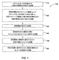
本発明は、口腔をスキャニングする方法、すなわち口腔のスキャニングを容易にする対応する方法を対象とし、
(a)スキャンすることを望む口腔の目標部分を特定する段階と、
(b)前記目標部分をスキャニング装置によってスキャンすることを可能にするのに適した、前記スキャニング装置と口腔の前記目標部分との空間的関係を特定する段階と、
(c)前記関係を表示する段階と、
(d)前記口腔をスキャンするためのガイドとして前記表示された関係を使用する段階とを備える。
The present invention is directed to a method of scanning the oral cavity, ie, a corresponding method that facilitates scanning of the oral cavity,
(A) identifying a target portion of the oral cavity desired to be scanned;
(B) identifying a spatial relationship between the scanning device and the target portion of the oral cavity suitable to allow the target portion to be scanned by a scanning device;
(C) displaying the relationship;
(D) using the displayed relationship as a guide for scanning the oral cavity.
その方法は、前記関係に実質的に適合するように前記口腔をスキャンする段階をさらに含む。 The method further includes scanning the oral cavity to substantially match the relationship.
そのスキャンする段階は、所定の処置に使用するために前記目標部分の3Dデータを提供する。段階(a)は、前記目標部分と関連する前記口腔内の補助的部分を特定する段階を含み得、前記所定の歯科処置に使用するために前記補助的部分の3Dデータがやはり必要とされる。段階(b)は、各前記目標部分および各前記補助的部分に対して、前記スキャニング装置に関し、一連の空間的パラメータを決定する段階であって、それぞれのパラメータは、前記スキャナが前記対応する目標部分または補助的部分を完全にスキャンすることを可能にするのに充分なスキャニングステーションのデータを備える段階を含み得る。任意選択的に、前記一連のスキャニングステーションのデータは、前記スキャナが前記目標部分または補助的部分の領域の3D形状データを得るのを可能にするような、前記目標部分または補助的部分に対する前記スキャナの近接度および相対的向きを含む。前記一連のパラメータが、対応する複数の前記領域の3D形状データを提供し、前記一連の前記空間的パラメータは、少なくとも一部の隣接する前記領域が互いに重なり合うように決定される。 The scanning step provides 3D data of the target portion for use in a predetermined procedure. Step (a) may include identifying an auxiliary portion in the oral cavity associated with the target portion, wherein 3D data of the auxiliary portion is still required for use in the predetermined dental procedure. . Step (b) is to determine a series of spatial parameters for the scanning device for each target portion and each auxiliary portion, each parameter being determined by the scanner for the corresponding target. It may include providing sufficient scanning station data to allow a complete scan of the part or auxiliary part. Optionally, the series of scanning station data allows the scanner for the target portion or auxiliary portion to enable the scanner to obtain 3D shape data of the region of the target portion or auxiliary portion. Including proximity and relative orientation. The set of parameters provides 3D shape data for a plurality of corresponding regions, and the set of spatial parameters is determined such that at least some of the adjacent regions overlap each other.
一実施形態では、段階(c)が、対応する前記目標部分および前記補助的部分を含む基準口腔の少なくとも一部の画像と、前記一連のパラメータの少なくとも1つのパラメータに対して段階(b)で決定される空間的関係に対応する相互の空間的関係にある基準スキャナの画像とを備える基準画像を表示する段階を含む。一連の前記基準画像が形成され得、前記一連の各画像が、前記一連のパラメータである前記パラメータのそれぞれ1つに対応する。その一連の画像が、所定の順序で表示され得る。任意選択的に、基準画像は3D属性を備える。その画像は、所定の座標システムに対して、所望のあらゆる向きの前記基準口腔を含むことができる。その座標システムが、たとえば、直交デカルト軸システムを含み得る。その向きが、歯科専門家の観察点からの患者の口腔への実際の視線に任意選択的に対応し得る。任意選択的に、使用者が次の画像へ進むのを援けるために、聴覚および/または視覚的合図が用いられている。 In one embodiment, step (c) comprises in step (b) for at least part of an image of a reference oral cavity including the corresponding target part and the auxiliary part and at least one parameter of the series of parameters. Displaying a reference image comprising images of reference scanners in mutual spatial relationship corresponding to the determined spatial relationship. A series of the reference images may be formed, each series of images corresponding to a respective one of the parameters being the series of parameters. The series of images can be displayed in a predetermined order. Optionally, the reference image has 3D attributes. The image can include the reference oral cavity in any desired orientation relative to a given coordinate system. The coordinate system may include, for example, an orthogonal Cartesian axis system. The orientation can optionally correspond to the actual line of sight of the patient's oral cavity from the point of view of the dental professional. Optionally, audio and / or visual cues are used to help the user advance to the next image.
別の実施形態では、段階(c)が、前記スキャナの視野のビデオ画像を表示することができるファインダ上に標示を表示する段階を含み、前記標示は、前記目標部分または補助的部分の所定の一部分が特定の方式でそれに対して結びつけられるある所望位置を示している。標示には、たとえば、「+」もしくは「X」またはあらゆる他の適切なシンボルが含まれ、そのシンボルは、たとえば、幾何学的、英数字的などであり得る。 In another embodiment, step (c) comprises displaying an indication on a viewfinder capable of displaying a video image of the scanner's field of view, the indication comprising a predetermined portion of the target portion or auxiliary portion. A portion indicates a desired position that is tied to it in a particular manner. The indication includes, for example, “+” or “X” or any other suitable symbol, which may be, for example, geometric, alphanumeric, etc.
この実施形態の変形形態として、その標示が、前記目標部分または補助的部分の前記ファインダ内での期待像に対応するプロファイルを表すシンボルを含む。光学的または画像認識法が、画像のプロファイルを得るために前記ビデオ画像に適用され得、前記シンボルが前記プロファイルを含む。たとえば、そのプロファイルが、前記ファインダを介して見た歯の輪郭として形成された形状線を含む。そのシンボルは、たとえば、上側、頬側、または下側のいずれか1つから見た歯の輪郭として形成された形状線を含み得る。 As a variant of this embodiment, the marking includes a symbol representing a profile corresponding to an expected image in the viewfinder of the target part or auxiliary part. Optical or image recognition methods can be applied to the video image to obtain a profile of the image, and the symbol includes the profile. For example, the profile includes a shape line formed as a tooth profile viewed through the viewfinder. The symbol may include, for example, a shape line formed as a tooth profile viewed from any one of the upper side, the buccal side, or the lower side.
任意選択的に、一連の標示が設定され、前記一連の各標示が、前記一連のパラメータである前記パラメータのそれぞれ1つに対応する。前記一連の標示が所定の順序で表示され、口腔が、前の前記パラメータおよび対応する標示に従ってスキャンされた後、次の標示が表示され得る。前記次の標示が、直前の標示と共に表示されることもある。任意選択的に、異なる前記パラメータに関する標示は、互いに異なる色で表示することができる。 Optionally, a series of signs is set, each series of signs corresponding to a respective one of the parameters being the series of parameters. The series of indications may be displayed in a predetermined order, and after the oral cavity has been scanned according to the previous parameters and corresponding indications, the next indication may be displayed. The next sign may be displayed together with the previous sign. Optionally, the indications for the different parameters can be displayed in different colors.
前述の処置は、たとえば、予備処理部に対するクラウンのための歯科補綴法であり、前記目標部分が、前記予備処理部を含み、前記補助的部分が、前記予備処理部に隣接する歯、および対向する顎から前記予備処理部に向き合う歯の少なくとも一部を含み得る。 The aforementioned procedure is, for example, a dental prosthesis for a crown against a pretreatment part, wherein the target part includes the pretreatment part, the auxiliary part is a tooth adjacent to the pretreatment part, and facing It may include at least a part of a tooth facing the pretreatment part from the jaw to be treated.
前述の処置は、たとえば、複数の予備処理部に関するブリッジのための歯科補綴法であり、前記目標部分が、前記予備処理部を含み、前記補助的部分が、最も遠心の予備処理部に隣接する歯、および最も近心の予備処理部に隣接する歯の少なくとも一部、ならびに反対側の顎から前記予備処理部に対向する歯の少なくとも一部を含み得る。 The aforementioned procedure is, for example, a dental prosthesis for a bridge for a plurality of pretreatment units, wherein the target portion includes the pretreatment portion and the auxiliary portion is adjacent to the most centrifugal pretreatment portion. It may include a tooth and at least a portion of the tooth adjacent to the most mesial pretreatment section, and at least a portion of the tooth facing the pretreatment section from the opposite jaw.
前述の処置は、たとえば、歯科矯正法であり、前記目標部分が、前記口腔の少なくとも1つの顎の歯列全体を含み得る。 The aforementioned procedure is, for example, an orthodontic method, and the target portion may include the entire dentition of at least one jaw of the oral cavity.
通常、本発明の方法は、コンピュータ化された方法であり、すなわち、部分的にまたは完全にコンピュータなどの処理装置の助けを得て実行される。ただし、少なくともいくつかの実施形態は、コンピュータを必要とせずに実施され得る。 Typically, the method of the present invention is a computerized method, i.e., partly or fully performed with the aid of a processing device such as a computer. However, at least some embodiments may be implemented without the need for a computer.
本発明はまた、患者の口腔のスキャニングをガイドするために実行可能なプログラムを具体的に実現する、コンピュータが読み取れる媒体であって、
(a)スキャンされることが望まれる口腔の目標部分を表す第1組のデータ、
(b)前記目標部分をスキャニング装置によってスキャンすることを可能にするのに適した、前記スキャニング装置と口腔の前記目標部分との空間的関係を表す第2組のデータと
を備える媒体に関する。
The present invention also provides a computer readable medium that specifically implements an executable program to guide scanning of the patient's oral cavity,
(A) a first set of data representing a target portion of the oral cavity that is desired to be scanned;
(B) a medium comprising a second set of data representing a spatial relationship between the scanning device and the target portion of the oral cavity, suitable for allowing the target portion to be scanned by a scanning device;
そのコンピュータ可読媒体は、たとえば前記第2組のデータを表示できるように前記第2組のデータを操作するための、操作ルーチン、コンピュータ指令などの手段をさらに備えることができる。 The computer readable medium may further comprise means such as an operating routine, a computer command, etc. for manipulating the second set of data such that, for example, the second set of data can be displayed.
媒体には、たとえば、光ディスク、磁気ディスク、磁気テープなどのいずれか1つが含まれ得る。 The medium may include any one of an optical disk, a magnetic disk, a magnetic tape, and the like, for example.
本発明はまた、
(A)スキャンすることを望む口腔の目標部分を特定するための入力モジュールと、
(B)前記目標部分をスキャニング装置によってスキャンすることを可能にするのに適した、前記スキャニング装置と口腔の前記目標部分との空間的関係を生成する処理モジュールと、
(C)前記関係を表示する表示モジュールと
を備える、口腔のスキャニングをガイドするシステムを対象とする。
The present invention also provides
(A) an input module for identifying a target portion of the oral cavity desired to be scanned;
(B) a processing module for generating a spatial relationship between the scanning device and the target portion of the oral cavity, suitable for allowing the target portion to be scanned by a scanning device;
(C) A system for guiding the scanning of the oral cavity, which includes a display module for displaying the relationship.
システムはまた、好ましくは、前記関係に従ってスキャニングするために適切なスキャナを備える。 The system also preferably comprises a suitable scanner for scanning according to said relationship.
本発明を理解し、それが実際にいかに実施され得るかを見るために、次に、単に非限定的な例として、いくつかの実施形態を、添付図面を参照して説明する。 In order to understand the present invention and see how it can be implemented in practice, several embodiments will now be described, by way of non-limiting example only, with reference to the accompanying drawings.
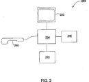
図1は、本発明の実施形態による3Dデータ取得プロセス100のブロック図を示し、図2は、本発明の実施形態による方法を実行するシステム200の主要要素を示す。システム200は、キーボード、マウス、タブレットなどの入力インターフェースまたはモジュール210と、通常、スクリーンまたはモニタであるが、追加または代替としてプリンタまたは他の表示システムを含むこともある出力装置または表示手段もしくはモジュール220と、たとえばCPUなどの処理装置またはモジュール230と、記憶装置240とを有するマイクロプロセッサまたは他の適切なコンピュータを通常備える。ある実施形態では、口腔の3Dデータを得るために適切なスキャナ250もまた、システム200に作動可能に接続され、それと対話し、一方、他の実施形態では、スキャナ250は、システム200となんらかの接続が必ずしもされていない別のシステムに3Dデータを提供することができる。有利には、たとえば、CB−CADの名の下に製造され、またはWO00/08415に開示されているように、一連の光線の共焦点結像によって3次元構造を求めるプローブを用いることができる。同特許の内容は、その全体が本明細書に組み込まれる。あるいは、3Dデータを得るための口腔のスキャンは、通常、手持ちプローブを備える適切な装置を使用して達成することもできる。
FIG. 1 shows a block diagram of a 3D
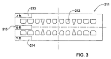
段階110で、口腔の目標部分が確認される。目標部分は、特定の患者に対する特定の歯科処置の焦点になり、そこに関し、その3D形状または表面データを得ることが望まれる口腔の部分(本明細書では区域または領域とも呼ばれる)である。目標部分は、通常、特別の処置が行われる一枚または複数の歯、または他の歯牙物質の部分を含み、ある場合には、下顎骨弓もしくは上顎骨弓、または両方の骨弓を含み得る。たとえば、処置が、特定の歯牙部位の予備処理部に適合するように設計され製作されたクラウン補綴物に関する歯科補綴法であり得る。そのような場合、歯科専門家は、処置の目標になった歯を、適切な規則に従って識別して、処理装置230に入力する。たとえば、図3を参照すると、表示装置220は、3次元(3D)属性を持たせるか、または簡単な2次元(2D)表示のいずれかで、基準的口腔の標準的画像または図式表示211を表示するのに使用される。ただし別法として、口腔の非図式的(たとえば英数字式)表示が提供されることもある。したがって、図3に示された例を参照すると、表示211は、複数のアイコン、画像、またはシンボル212を含み、そのそれぞれが正常な成人または子供の歯に対応する(患者の年齢は最初に処理装置230に入力されている)。処置の目標とする歯は、たとえば、適切なシンボル212をマウスの援けで「クリック」することによって識別することができる。あるいは、他の対話的方法、たとえばタッチスクリーン機構による手段が、目標とする歯を選択するのに使用することができる。別の例では、目標とする歯の識別情報が、従来の命名法、独自のコード体系を用いて、ドロップダウンメニュー上の選択などによって、または他の適切な方式で、処理装置230に手で入力することができ、処理装置230は使用者によってなされる選択を認識できるように適切にプログラムされている。
At
あるいは、ブリッジに関する歯科補綴法に関しては、ブリッジを受け入れる予備処理を施す作業を行う2本以上の歯が、たとえば、必要な変更を加えて上記と同様に、特定される。歯科矯正法に関しては、通常、片方または両方の顎の歯の全てが必要になる。そのような場合、上顎、下顎、または両顎の全ての歯が、たとえば、図3の213、214、215でそれぞれ示されるような、ただ1つの適切なシンボルによって選択することができる。 Alternatively, for a dental prosthesis for a bridge, two or more teeth that perform the preparatory work to accept the bridge are identified, for example, as described above, with the necessary changes. With respect to the orthodontic method, usually, it is necessary to all of the teeth of one or both of the jaw. In such a case, all teeth of the maxilla, mandible, or both jaws can be selected by a single appropriate symbol, for example as shown at 213, 214, 215 in FIG. 3, respectively.
口腔をどのようにスキャンする必要があるかは、説明が進むと明らかになるように、そこに適用される処置に依存する。したがって、歯科専門家はまた、実際の処置の識別情報を処理装置230に入力する。この目的のため、歯科専門家は、ドロップダウンメニューなどに予め設定された多数の選択肢から、アイコンから、または他の適切な図式入力インターフェースを介して処置を選択することができる。あるいは、処置の識別情報は、他の適切な方法、たとえば、予め設定されたコード、表示、または他の適切な方式によって入力することができ、処理装置230は、使用者によってなされる選択を認識できるように適切にプログラムされている。非限定的例として、当技術分野では公知の通り、処理を、歯科補綴法および歯科矯正法に大分類し、次いでさらに、これら処理の特定の形態に小分類することができる。
How the oral cavity needs to be scanned depends on the procedure applied to it, as will become clear as the description proceeds. Accordingly, the dental professional also inputs the identification information of the actual procedure into the
使用されるスキャナ250のタイプが、通常、複数の選択肢から1つを選択して、やはり処理装置に入力される。使用されているスキャナが処理装置230によって認識できない場合、それにも拘らず、その代わりに、スキャナの作動パラメータをそれに入力することが可能であり得る。たとえば、スキャナヘッドと歯の表面との間の最適な間隔、ならびにその間隔でスキャンすることが可能な歯牙面の捕捉領域(およびその形状)が提供され得る。あるいは、他の適切なスキャンパラメータが提供され得る。いずれの場合も、スキャナを用いて得られる歯列の仮想モデルが、既知の方式で実際の歯列に寸法的に関係付けられ得ることが望ましく、そのため、仮想モデルの寸法測定がなされ得る。
The type of
次の段階120では、処理装置230が、問題になっている処置に関して完全かつ正確な3Dデータを得ることができるように、口腔の適切な部分をスキャンするのに要求される必要な空間的関係を特定する。この段階は、口腔をスキャンする最適な方式を確立するために段階110で既に得られたデータを使用し、したがって前述のデータの特性に依存する。さらに、本発明の方法に従って、特別な処置のためにスキャンする必要のある追加または補助的な部分もまた特定され、スキャナとこれら部分との空間的関係が特定または決定される。目標部分および補助的部分が特定されると、スキャニングプロトコルが、スキャナのタイプ、その解像度、ならびに目標部分および補助的部分に対するスキャナヘッドと歯牙面との最適間隔での捕捉領域に関連させて、別々または一緒のいずれにでも、特定または決定される。スキャニングプロトコルは、通常、目標部分および補助的部分の歯牙面と空間的に関係付けられた一連のスキャニングステーションを備える。好ましくは、当業界では公知の通り、隣接するスキャニングステーションで得ることができる画像またはスキャンの有意な重なり合いが、良好な位置あわせができるようにスキャニングプロトコルに組み込まれており、各スキャニングステーションで得られる3Dデータが、一体にとじ合わされて合成3D仮想モデルを形成する。いくつかの例が次いで説明される。
In the
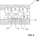
図4は、それに隣接する歯A、B、および、それと対向関係にある、他方の顎からの歯A’、P’およびB’を有する予備処理部P上にクラウン補綴物を必要とする、患者の口腔の理想化された部分300を示す。この理想化部分300は、通常、システム200の記憶装置240に格納された成人の理想化全歯列の3D仮想モデルである。理想化とは、理想化された歯列が、正常な相対位置にある成人の全ての歯の3Dモデルを備え、それら3Dモデルが、寸法、形状などに関し統計的平均に従って、人々に共通に見られる典型例として標準化されていることを単に意味する。当然、本発明の目的のためには、必要とする目的部分および補助部分で、患者の歯に対応する歯の3D仮想モデルを含んでいる限り、いかなる3D仮想モデルでも適合する。記憶装置240はまた、子供または特別な母集団群の歯の理想化仮想モデルも備え得、したがって、使用者は、通常、それに関して最も近い理想化仮想モデルが最適に決定される患者の年齢、または他の特性を特定する(また、そうするようにシステム200によって任意選択的に促され得る)。記憶装置240はまた、3D仮想モデル300の各仮想歯モデルに関して、理想化仮想予備処理モデルを備え、患者が必要とする歯科補綴法に従って、1つまたは複数の仮想歯が、対応する1つまたは複数の仮想予備処理部に置き換えられ得る。
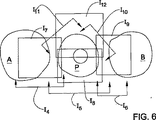
FIG. 4 requires a crown prosthesis on the pretreatment part P with the teeth A ′, P ′ and B ′ from the other jaw, the teeth A, B adjacent to it and the opposite jaws, An
スキャンされる目標領域または部分は、点線Tによって表されており、歯肉線の上側に終端線LTおよび元の歯の一部を有する予備処理部Pを含む。目標領域が極めて正確にスキャンされると、対応するコーピングまたは補綴物の内面を正確に設計することが可能になる。口腔の補助部分が点線AT内に含まれ、隣接する歯および対向する歯の一部、主として歯A、B、P’、また程度は低いがしばしばA’およびB’、またはそれらの一部を含む。通常、必ずしもではないが、補助部分ATのスキャンデータの解像度は、クラウン補綴物の外面(その設計は補助部分の歯牙面に依存する)の製作精度が、コーピングまたは補綴物の内面よりもかなり低くてもよいので、目標部分Tに対するよりも低くてよい。その解像度を含むスキャナの特定の性質または特性、および目標部分および補助的部分に対するスキャナヘッドと歯牙面との最適間隔での捕捉領域に従って、スキャニングプロトコルを以下のように設計することができる。 The target area or portion to be scanned is represented by a dotted line T and includes a preprocessing section P having a terminal line LT and a part of the original tooth above the gingival line. When the target area is scanned very accurately, it is possible to accurately design the inner surface of the corresponding coping or prosthesis. An auxiliary portion of the oral cavity is included within the dotted line AT and includes adjacent teeth and portions of opposing teeth, primarily teeth A, B, P ', and to a lesser extent often A' and B ', or portions thereof Including. Usually, but not necessarily, the resolution of the scan data of the auxiliary part AT is such that the production accuracy of the outer surface of the crown prosthesis (the design depends on the tooth surface of the auxiliary part) is considerably lower than the inner surface of the coping or prosthesis Therefore, it may be lower than the target portion T. According to the specific properties or characteristics of the scanner, including its resolution, and the capture area at the optimum distance between the scanner head and the tooth surface for the target and auxiliary parts, the scanning protocol can be designed as follows.
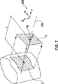
図7を参照すると、たとえば、各スキャニングステーションSi(本明細書では、捕捉ステーションとも呼ばれる)で、歯または予備処理部の歯牙面Xの領域Ii’内の3Dデータが、たとえば、スキャナ250によって捕捉され得、この領域は、スキャニングステーションSiでは、スキャナのスキャニング軸OAに直交し、歯牙面から寸法tだけ変位している平面上への領域Ii’の投影Iiによって表され得る。この寸法tは、通常、Iiと同等なスキャン領域を形成するのに、特定のスキャナにとって歯牙面Xに対する最適な間隔であるが、他の適切な間隔であってもよい。領域Iiの形状は、一般にスキャナに依存し、本明細書では矩形によって表される。スキャニング軸OAの向きは、基準座標軸、たとえばモデル300に関連して定義された直交デカルト軸320に関連付けることができ、直交デカルト軸320は、通常、実際の口腔内に容易に決定することができる。
Referring to FIG. 7, for example, at each scanning station S i (also referred to herein as a capture station), the 3D data in the region I i ′ of the tooth surface X of the tooth or pre-treatment unit is, for example, a
図5および6を参照すると、処理装置230は、目標部分Tおよび補助部分AT(やはり図4参照)を囲んで複数のスキャニングステーションSiを決定し、それにより、3Dデータをその中に得る対応する領域Ii’が合同して対象とする歯牙面の全範囲をその中に覆うようにする(ここでi=1,2,3,...10,11,12,13,14,..)。たとえば、図5では、領域I1、I2、13および領域I4、I5、I6が、2組の重なり合う3つの領域を表し、それぞれの領域は歯肉Gに対してほぼ2つの異なる高さに位置し、それらは、図4の下顎の目標部分Tおよび補助部分ATの頬側の部分を画成するのに充分であり得る。舌側を形成する同様な領域が必要なことがある。図6では、領域I4、I5、I6がU字型シンボルによって表されており、U字の腕はそれに沿ってスキャンが行われる方向、すなわちスキャナのスキャニング軸OAの空間的位置を表し、U字の中央部分は、縁から見た対応する投影Ii’を表す。したがって、例示的追加領域I10およびI11は、領域I4、I5、I6でのスキャンとは同一平面にない追加のスキャニングステーションを表す。同様に、図5および6の領域I7、I8、I9、I12、I13、I14は、歯の上側から取る追加のスキャニング領域を表し、目標部分Tの近傍に、より広い領域間の重なり合いが設けられる。たとえば、領域I13、I14を終端線の部分に対向させるほど、終端線の精度を上げることができる。スキャニングステーションSiの位置および方向は、これらステーションに対応する理想化モデルの領域Ii’が、その対応する目標部分Tおよび補助部分ATを適切に覆うように決定される。したがって、実際の口腔に対してスキャナ250のこれら位置および向きを再現することによって、より詳細に以下に記載されるように、目標部分Tおよび補助部分ATの必要な3Dデータを得ることができる。
Referring to FIGS. 5 and 6, the
目標部分Tおよび補助部分ATに含まれる対向する顎の歯牙面のスキャニングプロトコルは、下顎に関して上記で説明したのと同様に、必要なら変更を加えて、得ることができる。 The scanning protocol for the tooth surfaces of the opposing jaws included in the target part T and the auxiliary part AT can be obtained with modifications if necessary, as described above for the lower jaw.
通常、スキャニングプロトコルは、使用するスキャナの捕捉特性に応じて、同じ目標領域に対して異なるスキャナを使用すると、異なってくる。すなわち、各スキャンでより広い歯牙領域をスキャンすることができるスキャナ(たとえばより大きな視像ファイルを有する)は、比較的小さな歯牙面の3Dデータの捕捉しかできないスキャナより、スキャニングプロトコル中に定義されるスキャニングステーションが少なくてよい。同様に、矩形のスキャン挌子を有する(したがって、投影スキャニング領域Iiを対応する矩形の形態で形成する)スキャナのスキャニングステーションの数および配置は、通常、円形または三角形のスキャニング挌子を有するスキャナ(投影スキャニング領域Iiをそれぞれ対応する円形または三角形の形態で形成する)のそれらとは異なる。 Typically, the scanning protocol will differ when using different scanners for the same target area, depending on the capture characteristics of the scanner used. That is, a scanner that can scan a larger tooth area with each scan (eg, having a larger view file) is defined in the scanning protocol than a scanner that can only capture 3D data of a relatively small tooth surface. Fewer scanning stations. Similarly, the number and arrangement of scanner scanning stations with a rectangular scanning insulator (and thus forming the projection scanning area I i in the form of a corresponding rectangle) is typically a scanner with a circular or triangular scanning insulator. Different from those of (projecting scanning regions I i are respectively formed in the form of corresponding circles or triangles).
単一または複数の架工歯を有するブリッジの歯科補綴法に関する別の例(例示せず)では、一般に、ブリッジが固定される2つの予備処理部の一方および他方に関する2つの目標部分があり、またスキャンされる補助部分は、最も遠心の予備処理部に隣接する歯および最も近心の予備処理部に隣接する歯の少なくとも一部、ならびに反対側の顎から予備処理部に対向する歯の少なくとも一部を含む。 In another example (not shown) relating to a dental prosthesis for a bridge with single or multiple bridge teeth, there are generally two target portions for one and the other of the two pretreatment sections to which the bridge is fixed, Further, the auxiliary part to be scanned includes at least a part of the teeth adjacent to the most distal pretreatment part and the most mesial pretreatment part, and at least a tooth facing the pretreatment part from the opposite jaw. Includes some.
特定の歯の頬側または舌側部分の修復を要件とする歯科補綴法に関する別の例(例示せず)では、患者のこの目標部分のみを、補助部分として反対側の顎のいくつかの歯の咬合面と共に、スキャンする必要があり得る。 In another example of a dental prosthesis that requires repair of the buccal or lingual part of a particular tooth (not shown), only this target part of the patient is used as an auxiliary part with several teeth on the opposite jaw It may be necessary to scan along with the occlusal surface.
片方または両方の顎の歯科矯正法に関するさらに別の例(例示せず)では、目標部分は片方または両方の顎それぞれの完全な歯列を含み得る。 In yet another example (not shown) for orthodontic treatment of one or both jaws, the target portion may include a complete dentition for each of one or both jaws.
本発明によれば、システム200は、スキャナのパラメータ、処置法、処置する歯牙部位、患者の年齢などに基づいて毎回新しい理想化スキャニングプロトコルを計算し、理想化仮想モデル300に適用することができる。
In accordance with the present invention, the
あるいは、全ての必要なスキャニングプロトコルが、各スキャナのタイプ、処置法、年齢グループなどごとに事前に計算され、記憶装置240に格納され、提供された特定の患者/処置法/スキャナパラメータに従って特定されたとき、最も適切なプロトコルが記憶装置240から取り出される。この場合、患者ごとのスキャニングプロトコルを決定するために仮想モデル300を必要とすることはなくなり得る。したがって、特定の処置に関する必要なガイダンスの全てを、たとえば印刷本またはパンフレットなどの印刷形態で、映画またはビデオクリップによって、あるいは他の伝達媒体で提供することが可能になり、使用者は、たとえばインデックスなどを介して対象とする患者の特定のパラメータに従って適切なガイダンス画像などを捜し出し、次いで本/映画などの関係のあるページ/場面などを開いて、必要なガイダンスを得ることになる。
Alternatively, all necessary scanning protocols are pre-calculated for each scanner type, treatment method, age group, etc., stored in the
あるいは、記憶装置240が、異なる各タイプの処置法ごとに標準的スキャニングプロトコルを備え、このプロトコルが、患者の年齢、歯牙目標部分、スキャナの特性などを含むパラメータの少なくとも1つを考慮して処理装置230によって修正される。
Alternatively, the
段階130で、スキャニングステーションSiと口腔との空間的関係が表示され、その結果、段階140で、これらの表示された関係が、考慮されている特定の処置法に好適な3Dデータを得るのに適するように口腔をスキャンするために、ガイドとして歯科専門家によって使用され得る。前述の空間的関係を表示する多くのやり方があり、そのいくつかの例を、次いで説明する。
At
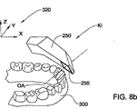
図8aおよび8bを参照すると、たとえば、特定のスキャニングステーションSiでのスキャナ250の理想化口腔300に対する空間的関係に対応して、たとえば、1対の透視図画像Kiが、スクリーン220上にまたは印刷物として表示され得る。追加または代替として、デフォルトにより、または処理装置230と対話することにより使用者が選択することによって、実際の口腔に関して歯科専門家が見るであろう観察点をたとえば含む、他の所望の観察点(視点)での関係を示す複数の画像が提供され得る。任意選択的に、当技術分野では公知の方式で、使用者が画像の観察点を対話式に変更することができる動的画像も提供され得る。あるいは、スキャナの一連の操作などを使用者に提供するビデオクリップなどが提供され得る。
Referring to FIGS. 8a and 8b, for example, a pair of perspective images K i are displayed on the
画像Kiは、スキャナ250の仮想モデルと、記憶装置240中に格納されている口腔300(通常、前述の理想化仮想モデル)の仮想モデルとの合成物であり得る。これらの仮想モデルは、処理装置230によって操作されて、事前に決定された特定のスキャニングステーションSiに従う仮想空間に、正確な空間的関係を形成し、当技術分野で公知の方式で、2次元画像として表示され得る。任意選択的に、スキャニングステーションSiの位置およびスキャニング軸OAの方向を、スキャナに追加またはそれに替えて、口腔300に関して表示することができる。スキャニング軸OAは、通常、スキャナのスキャニング面255に直角であるとして定義されるが、他の既知の適切な、スキャナの幾何学的または他のパラメータによって定義してもよい。画像Kiは、任意選択的に、座標システム、たとえば直交軸320の表示を備えることができ、その座標システムは、見ている観察点に適した向きになっている。
The image K i can be a composite of the virtual model of the
画像Kiにおいて、歯牙面を、たとえば図8aおよび8bに示すように、3D属性および実際の歯牙形態を有するものとして表示することが可能であり、あるいは、各歯牙面を、たとえば幾何学的形状で表すことができ、たとえば単純な楔形で門歯を表し、円錐で犬歯を表し、円筒で臼歯を表すことができる。 In the image K i, a tooth surface, for example, as shown in FIGS. 8a and 8b, it is possible to display as having a 3D attributes and actual tooth form, or the respective tooth surfaces, for example the geometry For example, an incisor can be represented by a simple wedge shape, a canine can be represented by a cone, and a molar can be represented by a cylinder.
任意選択的に、たとえば、複数のシンボル(たとえば、「X」もしくは「+」などの標示、または投影領域を表すフレームなど)が1つまたは複数の理想化歯列の画像上に重ね合わされた、たとえば図5および6に示されたものと同様な、全プロトコルを図示した総括合成画像が最初に提供(図示せず)され得る。 Optionally, for example, a plurality of symbols (eg, a label such as “X” or “+”, or a frame representing a projection region, etc.) are superimposed on the image of one or more idealized dentitions, For example, a summary composite image illustrating the entire protocol, similar to that shown in FIGS. 5 and 6, may first be provided (not shown).
さらに任意選択的に、画像Kiに現れる理想化仮想モデルは、患者に合わせて修正して、実際の予備処理が行われるべき各対応する歯牙領域での仮想予備処理部を示すことができ、また、実際の口腔では歯のないところ、たとえば架工歯を受け入れるために歯が取り除かれたところはモデルから仮想歯を取り除くことができる。これらの特徴は、各スキャニングステーションSiでのスキャナの位置および向きの特定をさらに容易にすることができる。 Further optionally, the idealized virtual model appearing in the image K i can be modified for the patient to show a virtual pre-processing section at each corresponding tooth region where the actual pre-processing is to be performed, Also, virtual teeth can be removed from the model where there are no teeth in the actual oral cavity, for example, where the teeth have been removed to accept the construction tooth. These features can make it easier to identify the position and orientation of the scanner at each scanning station S i .
さらに任意選択的に、各スキャニングステーションでスキャナの位置および向きを特定する非画像データが提供され得、これらデータは、たとえば、適切な対応する幾何学的データが記載され、また、たとえば、スキャナのスキャニング面255と対象とする歯牙面との間隔、スキャンされる特定の面の識別情報などを含む表の形で提供され得る。あるいは、段階130での関係が、たとえば、スキャナと歯の相対位置を記述する1組の指示または命令として、英数字の形で表示され得る。あるいは、段階130での関係が、可聴形態で表示され得、たとえば、そのような指示または命令が、予め録音されたものから、またはシステム200によって合成的に生成されてスピーカなどで放送される。
Further optionally, non-image data identifying the position and orientation of the scanner at each scanning station may be provided, which is described, for example, with the appropriate corresponding geometric data, and for example of the scanner It may be provided in the form of a table including the distance between the
さらに任意選択的に、スキャニングステーションSiを、所望の順序、たとえば、連続する各スキャン間の移動を最小限にするような順序で順次表示することができる。 Further optionally, the scanning stations S i can be displayed sequentially in a desired order, for example in an order that minimizes movement between successive scans.
この実施形態では、段階130は、表示された関係をスキャニングガイドとして用いる段階140、および前記関係に実質的に従うように口腔をスキャニングする段階150によって引き継がれる。歯科専門家の仕事を容易にするために、次のスキャニングステーションに対応する画像は、任意選択的に、歯科専門家が、現在のスキャニングステーションによって要求されたように自分は口腔を適切にスキャンしたと確信するまで表示されない。これは、スキャナ250を作動可能に処理装置230に接続し、スキャンが行われる(そしてそれが装置230によって検出される)たびに次のスキャニングステーションを表示するか否か使用者が尋ねられることによって達成される。あるいは、各スキャンの後で、スキャナによって撮られたビデオ画像を、このスキャニングステーションについてスキャナの観察点から見た理想化仮想モデルの理想化2D仮想画像と共に表示することが可能であり得、使用者が、2つの画像を比較し、特定のスキャンが所望の関係に充分に適合していると見なせるか否かを判断することができる。
In this embodiment,
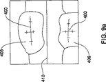
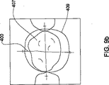
段階130の第2の実施形態が図9aおよび9bに示されており、この実施形態では、スキャナ250をガイドするために、ビデオ画像撮像能力を有するように構成されたスキャナ250のその能力を利用する。十字線400、咬合線410など適切なシンボルが、スキャナ250のファインダ上に重ね合わされ、通常、スクリーン220に表示(またはたとえばプリント)され得る。この実施形態では、段階120の空間的関係は、スキャナ250の観察点から表示され、スクリーン上、見ている歯牙面の特定の部分(たとえばスキャニング軸の特定の方向から見た歯の中央)の中心を合わせるべきところに、たとえば前述の十字線400などの基準マークを形成する形を取る。たとえば、図9aでは、スキャニングステーションにおける適切なスキャンは、スキャナによって頬側の方向から写された上側の歯405および下側の歯406(システムによって事前にスキャンの対象として特定されている)の中心がそれぞれ上側および下側の十字線400に合ったとき、行われ得る。同様に、図9bでは、上側から写した歯407の中心が十字線400と合っている。十字線400は、スキャナ250を介して見る歯407の中心を十字線400にさらに合わせ易くするリング401をさらに備えることができる。
A second embodiment of
次のスキャニングステーションへの進行およびその特定は、十字線400を、十字線400の最後の位置がスキャニングステーションの次の(今や現在の)位置において現れるスクリーン上の位置へ変位させることによって促進される。これは、使用者が前のスキャンが適切に行われたことに満足したとき、たとえば以前に図8a、8bの実施形態に関して記述したように、必要なら変更を加えて、処理装置230によって自動的に達成される。次いでスキャナは、十字線400(以前として前のスキャニングステーションでの仮想空間に関わっており、ここではファインダの再配置位置に現れている)が前の歯牙面の中心に再び合わされ、結果的にその歯牙が、スクリーンの中央位置から、今や移動させられた十字線400に再び結びつく位置に変位させられるように、移動させられる。これにより、スキャナを次のスキャニング位置に自動的に整合させる。たとえば、図10a〜10cを参照すると、図10aは、頬側から見た一連の歯の画像Lを示しており、十字線400は、1つの特定の歯410の中央に合わされ、隣接する歯411および412は部分的に見えている。使用者が、このスキャニングステーションで適切なスキャンが行われたと満足したとき、これが適切な方式でシステム200に知らされ、十字線400はスクリーン中央の前の位置から右に移動させられ、それにより、今や、十字線400の左側部分401だけしか見えなくなる。使用者は、そこで、ファインダ内の十字線400に対する歯410の相対位置を更新するように、たとえば図10bの画像に示されているところまで、スキャナを移動させ、それによりスキャンされる次の歯牙面、この場合は歯411が、ファインダの主要部分にもたらされて画像L’を形成する。前の画像L中の要素の相対位置は点線の枠として示されている。使用者の満足のいくようにこれが達成されると、古い位置の十字線400はスクリーンから取り除かれ、点線400’で示されるように、スクリーンの中央に再配置される。次いで、スキャンが、スキャニングステーションに該当するこの位置で実施される。図10cに示された次のスキャニングステーションへ移動するために、十字線400の新しい位置が、たとえばファインダの下側部分に再配置され、使用者はそれに対応して、十字線400に対して前の相対位置を保つように歯411を再配置すべくスキャナを平行移動させて、画像L”を形成する。前の画像の位置L’はこの図に点線の枠で示されている。このプロセスは、全てのスキャニングステーションを通過するまで繰り返される。スキャニングの方向を、たとえば頬側(図9a)から上側(図9b)へ完全に変える必要があることがあり、これは、移行が必要とされる特定の歯に使用者を導き、次いで、たとえば、基準マークの形をたとえば「+」標示から、現在の歯(または予備処理部)の上視が今取られようとしていること(またはどんな歯牙面が考慮されているか)を示す、円409(たとえば図9bに示されているような)も含むものへ変えることによって行われる。追加または代替として、文字または図式のプロンプトをスクリーンに表してもよく、あるいは、音声または他のプロンプトによりスピーカ(図示せず)を介して、次のスキャニングステーションに従って規定される位置の変更および/または別の歯牙部位への移動を使用者に促してもよい。
Progress to and identification of the next scanning station is facilitated by displacing the
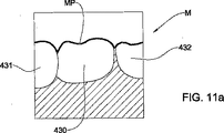
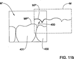
上記の段階130および140の第2の実施形態の変形形態として、使用者を次のスキャニングステーションに導くために、現在のスキャニングステーションでスキャンされている歯牙面の特徴を特定するのに光学的認識(画像認識としても知られている)法を採用することもできる。たとえば、図11aおよび11bを参照すると、画像Mは、現在のスキャニングステーションで得た、最後のスキャンに対応するビデオ画像である。画像Mは、隣接する歯431、432を側面に伴った歯430など、いくつかの歯牙面の舌側から見た相対位置を示す。適切な光学的または画像認識手段が、画像Mに適用され、画像Mは、先ず、適切なフレームグラバによって処理装置230で分離され、対象プロファイルMPが求められる。そのようなプロファイルMPは、スキャナ250の観察点から見た1つまたは複数の歯430、431、432の外縁を通常含み、すなわち、たとえば歯と背景のような光学的に異なる2つの領域を分ける架空線を通常含む。プロファイルMPは、次いで、画像M内のその最初の相対位置に、ファインダ内の画像として再生される。次いで、処理装置230が、次のスキャニングステーションへ移動するのに必要なスキャナの移動量を計算し、この移動量を仮想的にプロファイルMPに適用して、プロファイルMP、または最終的にはその一部を、図11bに示すように、ファインダ内の位置MP’へ再配置する。(これが、たとえば、上記の十字線400の新しい位置が、いかに同様に実際に計算され得るかを示す。)使用者は、次いで、ファインダによって視認される画像が再配置されたプロファイルMP’と位置が合うまで、前に計算された仮想移動量をなぞって、スキャナ250を移動させる。図11bは、完全に位置合わせされる前の画像M’を示し、スキャナ250は、プロファイルMP’がファインダを介して視認される歯の縁MP”の一部と重ね合わさるまで、矢印450の方向に移動されねばならない。
As a variation of the second embodiment of
異なるスキャニングステーション間の歯科専門家へのガイドは、上記では図式的表現として説明してきた。任意選択的に、または代替として、ガイドは、適切ないかなる形態をも取り得る。たとえば、処理装置230によって提供される、スキャニングステーションのデータ入力時に働く適切な音声ソフトウェアを使用して、たとえば、次にスキャナを左に3mm、上へ2mm移動させるように医師に要求する、口頭指示が提供され得る。あるいは、非口頭聴覚指示、たとえば符号化されたベル音やビープ音が提供されることもあり、そのパターンおよび強度が、使用者によって、たとえば多数の方向の中からの要求される移動として解釈され得る。
A guide to dental professionals between different scanning stations has been described above as a schematic representation. Optionally or alternatively, the guide may take any suitable form. For example, using appropriate voice software provided by the
追加または代替として、非図式的手段を、スキャニングステーション間で使用者をガイドするために使用することができる。たとえば、使用者を次のスキャニングステーションへの要求される方向へ導くために、たとえば、適切なLEDがファインダまたは矢印の画像中に設けられる。 Additionally or alternatively, non-schematic means can be used to guide the user between scanning stations. For example, suitable LEDs are provided in the viewfinder or arrow image, for example, to guide the user in the required direction to the next scanning station.
有利には、スキャナ250は、慣性システムまたは適切な追跡システムを備え、それらシステムは、基準位置/向きに対するスキャナの位置/向きの変化を求めることができる。したがって、スキャナ250の実際の位置/向きを、次のスキャンのための所望の位置に対して自動的に点検することができ、適切な手段、たとえば聴覚および/または視覚手段を、現在位置と所望位置との差に基づいて正しい位置へ使用者を導くのに使用することができる。たとえば、スキャナ250が所望の位置に近付くほど周波数が増加するビープ音を鳴らしてもよい。任意選択的に、第2の慣性または追跡システムを患者の頭または顎に結合し、それにより、患者の顎の動きを相殺してもよい。
Advantageously, the
任意選択的に、各標示が順次それぞれのスキャニングステーションに対応する一連の標示を設けることができる。一連の標示を所定の順序で表示することができ、その対応する標示を有する前のスキャニングステーションで口腔がスキャンされた後、次の標示が表示される。任意選択的に、次の標示を、現在、すなわち直前の標示と共に表示することができる。異なる前記パラメータに関する標示は、互いに異なる色で表示される。すなわち、これら標示は、たとえば、使用者がどのスキャニングステーションに居て、どれが次のステーションか特定するのに役立つ。その標示は、たとえば、一連の数(たとえば「1/4」、「2/4」、「3/4」、「4/4」)またはシンボルを含んでもよい。 Optionally, a series of indications can be provided, with each indication sequentially corresponding to a respective scanning station. A series of signs can be displayed in a predetermined order, and the next sign is displayed after the oral cavity has been scanned at the previous scanning station with the corresponding sign. Optionally, the next sign can be displayed along with the current, ie, previous sign. The indications relating to the different parameters are displayed in different colors. That is, these signs help, for example, to identify which scanning station the user is at and which is the next station. The indication may include, for example, a series of numbers (eg, “1/4”, “2/4”, “3/4”, “4/4”) or symbols.
本発明の別の態様では、患者の口腔のスキャニングをガイドするために実行可能なプログラムを具体的に実現する、コンピュータが読み取れる媒体が提供される。コンピュータが読み取れる媒体は、
(a)スキャンされることが望まれる口腔の目標部分を表す第1組のデータと、
(b)前記目標部分を前記スキャニング装置によってスキャンすることを可能にするのに適切な、スキャニング装置と口腔の前記目標部分との空間的関係を表す第2組のデータと、
(c)前記第2のデータを表示する手段と
を備える。
In another aspect of the invention, a computer readable medium is provided that specifically implements a program executable to guide scanning of a patient's oral cavity. Computer-readable media
(A) a first set of data representing a target portion of the oral cavity that is desired to be scanned;
(B) a second set of data representing a spatial relationship between the scanning device and the target portion of the oral cavity suitable to allow the target portion to be scanned by the scanning device;
(C) means for displaying the second data.
媒体には、たとえば、光ディスク、磁気ディスク、磁気テープなどが含まれ得る。 The medium can include, for example, an optical disk, a magnetic disk, a magnetic tape, and the like.
本発明のある態様によれば、口腔のスキャニングのための、またはスキャニングを容易にするための方法およびシステムが提供される。スキャンすることが望まれる口腔の目標部分が特定され、前記目標部分を前記スキャニング装置によってスキャンすることを可能にするのに適したスキャニング装置と口腔の目標部分との空間的関係が、やはり特定されまたは別様に決定される。次いで、これら関係が表示され、表示された関係は、口腔をスキャンするためのガイドとして使用される。 In accordance with certain aspects of the present invention, methods and systems are provided for or for facilitating scanning of the oral cavity. The target portion of the oral cavity that is desired to be scanned is identified, and the spatial relationship between the scanning device and the target portion of the oral cavity suitable to allow the target portion to be scanned by the scanning device is also identified. Or decided otherwise. These relationships are then displayed, and the displayed relationships are used as a guide for scanning the oral cavity.
添付の方法の特許請求の範囲で、クレームの段階を呼称するのに使用されている英数字およびローマ数字は、単に便宜的に用いられているものであり、諸段階を実行する特定の順序をなんら意味するものではない。 In the appended method claims, the alphanumeric and Roman numerals used to refer to a step in a claim are for convenience only and may refer to a specific order in which the steps are performed. It doesn't mean anything.
最後に、添付特許請求の範囲を通じて使用されている単語「備える」は、「含むがそれに限定されない」ことを意味すると解釈されるべきことに留意されたい。 Finally, it should be noted that the word “comprising” as used throughout the appended claims should be construed to mean “including but not limited to”.
本発明による例示的実施形態が示され開示されてきたが、本発明の精神から逸脱することなく、多くの変更をそれに加えることができることが理解されよう。 While exemplary embodiments according to the present invention have been shown and disclosed, it will be appreciated that many changes may be made thereto without departing from the spirit of the invention.
100 データ取得プロセス
200 システム
210 入力インターフェース
211 表示
212 シンボル
213 シンボル
214 シンボル
215 シンボル
220 表示装置
230 処理装置
240 記憶装置
250 スキャナ
255 スキャニング面
300 仮想モデル
320 直交デカルト軸
400 十字線
401 リング
401 十字線の左側部分
405 上側の歯
406 下側の歯
407 歯
409 円
410 咬合線
410 歯
411 歯
430 歯
431 歯
432 歯
450 矢印
100
Claims (18)
(a)口腔の予め決められたスキャニングに従ってスキャンすることを望む口腔の複数の目標部分を第1デジタルモデルにおいて特定する段階と、
(b)予め決められた前記スキャニングの実行を介した実際のスキャニングの前に、コンピュータが読み取れる媒体に統合されたスキャニングプロトコルを生成する段階であって、前記スキャニングプロトコルが複数の予め決められたスキャニングステーションを備え、予め決められた前記スキャニングステーションそれぞれが、スキャニング装置と前記口腔の目標部分との間で特定された予め決められた空間的関係を備え、前記スキャニング装置を用いて前記口腔を実際にスキャニングしている間に前記目標部分の所望の3D画像を得ることが可能である、段階と、
を備える方法。A method of generating a computer-implemented guide protocol for scanning the oral cavity,
(A) identifying in the first digital model a plurality of target portions of the oral cavity that are desired to be scanned according to a predetermined scanning of the oral cavity;
(B) generating a scanning protocol integrated into a computer readable medium prior to actual scanning via the predetermined execution of the scanning, wherein the scanning protocol comprises a plurality of predetermined scanning; Each of the predetermined scanning stations is provided with a predetermined spatial relationship specified between the scanning device and the target portion of the oral cavity, and the oral cavity is actually used with the scanning device. A desired 3D image of the target portion can be obtained while scanning; and
A method comprising:
前記基準画像は、所定の座標システムに対して、所望のあらゆる向きの前記基準口腔を含むことができること、及び
使用者が次の画像へ進むのを援けるために、聴覚および/または視覚的合図が用いられること、
の少なくとも1つを特徴とする、請求項7に記載の方法。The series of images is displayed in a predetermined order;
The reference image can include the reference oral cavity in any desired orientation with respect to a given coordinate system, and audio and / or visual cues to help the user proceed to the next image Is used,
The method of claim 7, characterized by at least one of:
前記標示が、前記目標部分もしくは補助的部分の前記ファインダ内での期待像に対応するプロファイルを表すシンボルを含み、光学的認識法が、画像のプロファイルを得るために前記ビデオ画像に適用され、前記シンボルが前記プロファイルを含み、前記プロファイルが、前記ファインダによって見た歯の輪郭として形成された形状線を含むこと、
前記標示が、前記目標部分もしくは補助的部分の前記ファインダ内での期待像に対応するプロファイルを表すシンボルを含み、前記シンボルが、上側、頬側、または下側のいずれか1つから見た歯の輪郭として形成された形状線を含むこと、
一連の標示が設定され、前記一連の各標示が、前記一連のパラメータである前記パラメータのそれぞれ1つに対応すること、及び、
一連の標示が設定され、前記一連の各標示が、前記一連の空間的パラメータのうちの異なる1つの前記空間的パラメータに対応し、前記一連の標示が所定の順序で表示されること、
の少なくとも1つを特徴とする、請求項10に記載の方法。The marking includes a symbol representing a profile corresponding to an expected image in the viewfinder of the target portion or auxiliary portion, or “+” or “X”;
Said indicia, see contains a symbol representing the corresponding profile to the expected image in the viewfinder of the target portion or auxiliary parts, optical histological recognition method is applied to the video image in order to obtain an image profile The symbol includes the profile, and the profile includes a shape line formed as a tooth profile viewed by the finder;
The sign includes a symbol representing a profile corresponding to an expected image in the finder of the target portion or auxiliary portion, and the symbol is a tooth viewed from any one of upper side, buccal side, or lower side Including a shape line formed as an outline of
A series of signs is set, each series of signs corresponding to a respective one of the parameters being the series of parameters; and
A series of indications is set, each series of indications corresponding to a different one of the spatial parameters of the series of spatial parameters, the series of indications being displayed in a predetermined order;
The method of claim 10, characterized by at least one of the following:
予備処理部に関するクラウンのための歯科補綴法であって、前記目標部分が、前記予備処理部を含み、前記補助的部分が、前記予備処理部に隣接する歯、および反対側の顎から前記予備処理部に対向する歯の少なくとも一部を含む、歯科補綴法、
複数の予備処理部に関するブリッジのための歯科補綴法であって、前記目標部分が、前記予備処理部を含み、前記補助的部分が、最も遠心の予備処理部に隣接する歯、および最も近心の予備処理部に隣接する歯の少なくとも一部、ならびに反対側の顎から前記予備処理部に対向する歯の少なくとも一部を含む、歯科補綴法、及び、
歯科矯正法であって、前記複数の目標部分が、前記口腔の少なくとも1つの顎の歯列全体を含む、歯科矯正法、
のいずれか1つに関する、請求項2から11のいずれか一項に記載の方法。The scanning protocol is
A dental prosthesis for a crown with respect to a pretreatment section, wherein the target portion includes the pretreatment portion, and the auxiliary portion comprises the pretreatment from a tooth adjacent to the pretreatment portion and an opposite jaw. A dental prosthesis comprising at least part of the teeth facing the treatment part,
A dental prosthesis for a bridge for a plurality of pretreatment units, wherein the target portion includes the pretreatment portion, the auxiliary portion is a tooth adjacent to the most distal pretreatment portion, and the most mesial A dental prosthesis comprising at least a portion of the teeth adjacent to the pretreatment section, and at least a portion of the teeth facing the pretreatment section from the opposite jaw; and
An orthodontic method, wherein the plurality of target portions include an entire dentition of at least one jaw of the oral cavity,
12. A method according to any one of claims 2 to 11 relating to any one of the following.
(a)前記口腔の予め決められたスキャニングに従ってスキャンされることが望まれる口腔の複数の目標部分を表す第1組のデータと、
(b)複数の予め決められたスキャニングステーションを含むスキャニングプロトコルを表す第2組のデータであって、予め決められたスキャニングステーションそれぞれがスキャニング装置と口腔の目標部分との特定された予め決められた空間的関係を含み、前記スキャニング装置を用いて前記口腔を実際にスキャニングする間に、前記目標部分の所望の3D画像データを得ることが可能である、第2組のデータと、
を備える媒体。A computer readable medium that integrates an executable program to guide scanning of a patient's oral cavity,
(A) a first set of data representing a plurality of target portions of the oral cavity that are desired to be scanned according to a predetermined scanning of the oral cavity;
(B) a second set of data representing a scanning protocol including a plurality of predetermined scanning stations, each of the predetermined scanning stations being identified and predetermined between the scanning device and the target portion of the oral cavity A second set of data including a spatial relationship and capable of obtaining desired 3D image data of the target portion while actually scanning the oral cavity using the scanning device;
A medium comprising:
前記口腔の予め決められたスキャニングに従ってスキャンすることを望む、口腔の複数の目標部分を第1デジタルモデルにおいて特定するための入力モジュールと、
複数の予め決められたスキャニングステーションを備えるスキャニングプロコトルを生成する処理モジュールであって、予め決められた前記スキャニングステーションそれぞれが、スキャニング装置と前記口腔の目標部分との間で特定された予め決められた空間的関係を備え、前記スキャニング装置を用いて前記口腔を実際にスキャニングしている間に前記目標部分の所望の3D画像を得ることが可能である、処理モジュールと、
前記スキャニング装置と前記口腔の前記目標部分との間の特定した予め決められた前記空間的関係を表示する表示モジュールと
を備える、口腔のスキャニングをガイドするシステム。A system for guiding the scanning of the oral cavity,
An input module for identifying in the first digital model a plurality of target portions of the oral cavity that are desired to be scanned according to a predetermined scanning of the oral cavity;
A processing module for generating a scanning protocol comprising a plurality of predetermined scanning stations, wherein each of the predetermined scanning stations is identified between a scanning device and a target portion of the oral cavity. A processing module comprising a spatial relationship and capable of obtaining a desired 3D image of the target portion while actually scanning the oral cavity using the scanning device;
A system for guiding oral scanning, comprising: a display module for displaying the specified predetermined spatial relationship between the scanning device and the target portion of the oral cavity.
Applications Claiming Priority (3)
| Application Number | Priority Date | Filing Date | Title |
|---|---|---|---|
| US65770505P | 2005-03-03 | 2005-03-03 | |
| US60/657,705 | 2005-03-03 | ||
| PCT/IL2006/000292 WO2006092800A2 (en) | 2005-03-03 | 2006-03-02 | System and method for scanning an intraoral cavity |
Publications (2)
| Publication Number | Publication Date |
|---|---|
| JP2008537494A JP2008537494A (en) | 2008-09-18 |
| JP5154955B2 true JP5154955B2 (en) | 2013-02-27 |
Family
ID=36941559
Family Applications (1)
| Application Number | Title | Priority Date | Filing Date |
|---|---|---|---|
| JP2007557670A Expired - Lifetime JP5154955B2 (en) | 2005-03-03 | 2006-03-02 | Oral scanning system and method |
Country Status (5)
| Country | Link |
|---|---|
| US (7) | US7286954B2 (en) |
| EP (1) | EP1869403B1 (en) |
| JP (1) | JP5154955B2 (en) |
| ES (1) | ES2632937T3 (en) |
| WO (1) | WO2006092800A2 (en) |
Cited By (3)
| Publication number | Priority date | Publication date | Assignee | Title |
|---|---|---|---|---|
| KR101854729B1 (en) | 2016-12-21 | 2018-05-04 | 주식회사 디디에스 | Design System for Dental fixture |
| KR20180060502A (en) * | 2016-11-29 | 2018-06-07 | 주식회사 디디에스 | Data Conversion Device for Processing Dental fixture And Design Method for Dental fixture using thereof |
| WO2025048180A1 (en) * | 2023-08-31 | 2025-03-06 | 아크리얼 주식회사 | Method and system for providing visual guide for oral scanner |
Families Citing this family (224)
| Publication number | Priority date | Publication date | Assignee | Title |
|---|---|---|---|---|
| US11026768B2 (en) | 1998-10-08 | 2021-06-08 | Align Technology, Inc. | Dental appliance reinforcement |
| US8251699B2 (en) | 2002-12-31 | 2012-08-28 | Brian C. Reising | Orthodontic bracket and method of attaching orthodontic brackets to teeth |
| US9492245B2 (en) | 2004-02-27 | 2016-11-15 | Align Technology, Inc. | Method and system for providing dynamic orthodontic assessment and treatment profiles |
| JP5154955B2 (en) | 2005-03-03 | 2013-02-27 | カデント・リミテツド | Oral scanning system and method |
| US8447378B2 (en) * | 2005-03-11 | 2013-05-21 | Apteryx, Inc. | System and method of capturing images |
| US8265729B2 (en) * | 2005-03-11 | 2012-09-11 | Apteryx, Inc. | Third party acquisition of images at the direction of an independent imaging application |
| US7318001B2 (en) * | 2005-05-03 | 2008-01-08 | Cnv Technologies, Llc | Method and apparatus for collecting data for detecting and locating disturbances |
| EP1906862B1 (en) | 2005-06-30 | 2018-05-23 | Biomet 3i, LLC | Method of creating a dental laboratory model |
| US8257083B2 (en) | 2005-10-24 | 2012-09-04 | Biomet 3I, Llc | Methods for placing an implant analog in a physical model of the patient's mouth |
| US11219511B2 (en) | 2005-10-24 | 2022-01-11 | Biomet 3I, Llc | Methods for placing an implant analog in a physical model of the patient's mouth |
| US7698014B2 (en) | 2006-01-20 | 2010-04-13 | 3M Innovative Properties Company | Local enforcement of accuracy in fabricated models |
| US7912257B2 (en) * | 2006-01-20 | 2011-03-22 | 3M Innovative Properties Company | Real time display of acquired 3D dental data |
| US7599538B2 (en) * | 2006-07-24 | 2009-10-06 | Apteryx, Inc. | Method and system for automatic intra-oral sensor locating for image acquisition |
| US7812989B2 (en) * | 2006-09-29 | 2010-10-12 | Samsung Electronics Co., Ltd. | System and method for voice help on a topic the user selects at the device, or to correct an error at a multi-function peripheral (MFP) |
| US7835811B2 (en) | 2006-10-07 | 2010-11-16 | Voxelogix Corporation | Surgical guides and methods for positioning artificial teeth and dental implants |
| JP5330254B2 (en) | 2006-10-27 | 2013-10-30 | ノベル バイオケア サーヴィシィズ アーゲー | Method and appliance for acquiring data for dental components and physical dental models |
| WO2008051129A1 (en) | 2006-10-27 | 2008-05-02 | Nobel Biocare Services Ag | A dental impression tray for use in obtaining an impression of a dental structure |
| US7916911B2 (en) | 2007-02-26 | 2011-03-29 | Align Technology, Inc. | System and method for digital tooth imaging |
| EP1982652A1 (en) | 2007-04-20 | 2008-10-22 | Medicim NV | Method for deriving shape information |
| US8206153B2 (en) | 2007-05-18 | 2012-06-26 | Biomet 3I, Inc. | Method for selecting implant components |
| US7878805B2 (en) | 2007-05-25 | 2011-02-01 | Align Technology, Inc. | Tabbed dental appliance |
| KR101380771B1 (en) * | 2007-05-25 | 2014-04-11 | 노벨 바이오케어 서비시스 아게 | Method and system for dental planning |
| US9222768B2 (en) | 2007-06-26 | 2015-12-29 | Maurice Moshe Ernst | Supplemental scene reference surface devices for three-dimensional mapping |
| DE102007043366A1 (en) * | 2007-09-12 | 2009-03-19 | Degudent Gmbh | Method for determining the position of an intraoral measuring device |
| US8738394B2 (en) | 2007-11-08 | 2014-05-27 | Eric E. Kuo | Clinical data file |
| EP2060240A3 (en) | 2007-11-16 | 2009-08-12 | Biomet 3i, LLC | Components for use with a surgical guide for dental implant placement |
| US8108189B2 (en) | 2008-03-25 | 2012-01-31 | Align Technologies, Inc. | Reconstruction of non-visible part of tooth |
| JP2011517612A (en) | 2008-04-15 | 2011-06-16 | バイオメット・3アイ・エルエルシー | Method for generating accurate bone and soft tissue digital dental models |
| EP3415112B1 (en) | 2008-04-16 | 2022-05-25 | Biomet 3I, LLC | Method for the virtual development of a surgical guide for dental implants |
| WO2009135735A2 (en) * | 2008-05-08 | 2009-11-12 | Degudent Gmbh | Method for determining 3d data from at least one prepared maxillary area |
| US9492243B2 (en) | 2008-05-23 | 2016-11-15 | Align Technology, Inc. | Dental implant positioning |
| US8092215B2 (en) | 2008-05-23 | 2012-01-10 | Align Technology, Inc. | Smile designer |
| US20090306990A1 (en) * | 2008-06-04 | 2009-12-10 | Doug Vandervoort | Voice actuated and operator voice prompted coordinate measuring system |
| US8172569B2 (en) | 2008-06-12 | 2012-05-08 | Align Technology, Inc. | Dental appliance |
| WO2010001401A1 (en) | 2008-07-03 | 2010-01-07 | Cadent Ltd. | Method, apparatus and system for use in dental procedures |
| WO2010023582A1 (en) * | 2008-08-25 | 2010-03-04 | Koninklijke Philips Electronics, N.V. | System for detection, treatment and coverage feedback of oral health conditions |
| CH699575A1 (en) * | 2008-10-06 | 2010-04-15 | Nectar Imaging S R L | An optical system for a confocal microscope. |
| US8152518B2 (en) | 2008-10-08 | 2012-04-10 | Align Technology, Inc. | Dental positioning appliance having metallic portion |
| US10603008B2 (en) * | 2009-02-19 | 2020-03-31 | Tessonics Corporation | Ultrasonic device for assessment of internal tooth structure |
| US8292617B2 (en) | 2009-03-19 | 2012-10-23 | Align Technology, Inc. | Dental wire attachment |
| EP2229914B1 (en) * | 2009-03-20 | 2018-05-30 | Nobel Biocare Services AG | System and method for aligning virtual models |
| DK2442720T3 (en) | 2009-06-17 | 2016-12-19 | 3Shape As | Focus scan devices |
| DE102009026248A1 (en) * | 2009-07-24 | 2011-01-27 | Degudent Gmbh | Generation of a complete data record |
| US8765031B2 (en) | 2009-08-13 | 2014-07-01 | Align Technology, Inc. | Method of forming a dental appliance |
| US9848958B2 (en) | 2009-11-02 | 2017-12-26 | Align Technology, Inc. | Generating a dynamic three-dimensional occlusogram |
| US8348669B1 (en) | 2009-11-04 | 2013-01-08 | Bankruptcy Estate Of Voxelogix Corporation | Surgical template and method for positioning dental casts and dental implants |
| US9934360B2 (en) * | 2010-02-10 | 2018-04-03 | Biocad Medical, Inc. | Dental data planning |
| US9211166B2 (en) | 2010-04-30 | 2015-12-15 | Align Technology, Inc. | Individualized orthodontic treatment index |
| US9241774B2 (en) | 2010-04-30 | 2016-01-26 | Align Technology, Inc. | Patterned dental positioning appliance |
| FI129779B (en) * | 2010-07-19 | 2022-08-31 | Palodex Group Oy | Method and device for processing an intraoral image |
| EP3813027B1 (en) | 2010-07-19 | 2025-02-19 | Align Technology, Inc. | Methods and systems for creating and interacting with three dimensional virtual models |
| US20120062557A1 (en) * | 2010-09-10 | 2012-03-15 | Dimensional Photonics International, Inc. | Systems and methods for processing and displaying intra-oral measurement data |
| US9157733B2 (en) * | 2010-09-10 | 2015-10-13 | Dimensional Photonics International, Inc. | Method of data acquisition for three-dimensional imaging |
| EP2632386B1 (en) | 2010-10-29 | 2019-05-08 | 3Shape A/S | Designing a virtual preparation and a virtual gingival |
| USRE48221E1 (en) | 2010-12-06 | 2020-09-22 | 3Shape A/S | System with 3D user interface integration |
| ES2477288T3 (en) | 2010-12-07 | 2014-07-16 | Biomet 3I, Llc | Universal scanning element for use in a dental implant and dental implant analogues |
| EP3915511A1 (en) | 2010-12-21 | 2021-12-01 | 3Shape A/S | Motion blur compensation |
| EP2664272A4 (en) * | 2011-01-11 | 2014-06-25 | Advance Kk | Oral imaging and display system |
| JP5651132B2 (en) * | 2011-01-11 | 2015-01-07 | 株式会社アドバンス | Intraoral radiography display system |
| US8944818B2 (en) | 2011-05-16 | 2015-02-03 | Biomet 3I, Llc | Temporary abutment with combination of scanning features and provisionalization features |
| FR2977469B1 (en) * | 2011-07-08 | 2013-08-02 | Francois Duret | THREE-DIMENSIONAL MEASURING DEVICE USED IN THE DENTAL FIELD |
| US9403238B2 (en) | 2011-09-21 | 2016-08-02 | Align Technology, Inc. | Laser cutting |
| EP3348229B1 (en) * | 2011-11-15 | 2020-03-11 | Trispera Dental Inc. | Method and system for acquiring data from an individual for preparing a 3d model |
| US9089382B2 (en) | 2012-01-23 | 2015-07-28 | Biomet 3I, Llc | Method and apparatus for recording spatial gingival soft tissue relationship to implant placement within alveolar bone for immediate-implant placement |
| US9452032B2 (en) | 2012-01-23 | 2016-09-27 | Biomet 3I, Llc | Soft tissue preservation temporary (shell) immediate-implant abutment with biological active surface |
| US9375300B2 (en) | 2012-02-02 | 2016-06-28 | Align Technology, Inc. | Identifying forces on a tooth |
| WO2013126532A1 (en) * | 2012-02-21 | 2013-08-29 | Friddell Joel | Wireless intra-oral imaging system and method |
| US9220580B2 (en) | 2012-03-01 | 2015-12-29 | Align Technology, Inc. | Determining a dental treatment difficulty |
| US9198627B2 (en) | 2012-04-16 | 2015-12-01 | Biomet 3i | System and method for improved intra-oral scanning protocol and calibration |
| DE102012207499B3 (en) * | 2012-05-07 | 2013-09-05 | Sirona Dental Systems Gmbh | Method for measuring a dental situation |
| US9414897B2 (en) | 2012-05-22 | 2016-08-16 | Align Technology, Inc. | Adjustment of tooth position in a virtual dental model |
| FI125322B (en) * | 2012-06-11 | 2015-08-31 | Planmeca Oy | Tandytmodeller |
| US20140080092A1 (en) | 2012-09-14 | 2014-03-20 | Biomet 3I, Llc | Temporary dental prosthesis for use in developing final dental prosthesis |
| KR101457108B1 (en) * | 2012-09-25 | 2014-10-31 | 데오덴탈 주식회사 | Scanner for oral cavity |
| US9192305B2 (en) | 2012-09-28 | 2015-11-24 | Align Technology, Inc. | Estimating a surface texture of a tooth |
| US8948482B2 (en) | 2012-11-01 | 2015-02-03 | Align Technology, Inc. | Motion compensation in a three dimensional scan |
| US10098714B2 (en) * | 2012-12-19 | 2018-10-16 | Align Technology, Inc. | Apparatus and method for optically scanning an object in registration with a reference pattern |
| US10617489B2 (en) | 2012-12-19 | 2020-04-14 | Align Technology, Inc. | Creating a digital dental model of a patient's teeth using interproximal information |
| US9668829B2 (en) | 2012-12-19 | 2017-06-06 | Align Technology, Inc. | Methods and systems for dental procedures |
| US8926328B2 (en) | 2012-12-27 | 2015-01-06 | Biomet 3I, Llc | Jigs for placing dental implant analogs in models and methods of doing the same |
| SE1350114A1 (en) | 2013-01-31 | 2014-08-01 | Heraeus Dental Ab | Method of manufacturing a dental superstructure |
| DE102014104993A1 (en) * | 2013-06-24 | 2014-12-24 | Qioptiq Photonics Gmbh & Co. Kg | Dental measuring device for the three-dimensional measurement of teeth |
| US9393087B2 (en) | 2013-08-01 | 2016-07-19 | Align Technology, Inc. | Methods and systems for generating color images |
| FR3010629B1 (en) | 2013-09-19 | 2018-02-16 | Dental Monitoring | METHOD FOR CONTROLLING THE POSITIONING OF TEETH |
| EP3998040B1 (en) | 2013-12-20 | 2025-09-03 | Biomet 3i, LLC | Dental method for developing custom prostheses through scanning of coded members |
| US10111714B2 (en) | 2014-01-27 | 2018-10-30 | Align Technology, Inc. | Adhesive objects for improving image registration of intraoral images |
| WO2015118120A1 (en) | 2014-02-07 | 2015-08-13 | 3Shape A/S | Detecting tooth shade |
| US10111581B2 (en) * | 2014-02-27 | 2018-10-30 | Align Technology, Inc. | Thermal defogging system and method |
| DE102014207667A1 (en) | 2014-04-23 | 2015-10-29 | Sirona Dental Systems Gmbh | Method for carrying out an optical three-dimensional recording |
| US9510757B2 (en) * | 2014-05-07 | 2016-12-06 | Align Technology, Inc. | Identification of areas of interest during intraoral scans |
| US9431887B2 (en) | 2014-06-06 | 2016-08-30 | Align Technology, Inc. | Lens positioning system |
| US9491863B2 (en) | 2014-06-26 | 2016-11-08 | Align Technology, Inc. | Mounting system that maintains stability of optics as temperature changes |
| US9439568B2 (en) | 2014-07-03 | 2016-09-13 | Align Technology, Inc. | Apparatus and method for measuring surface topography optically |
| US10772506B2 (en) | 2014-07-07 | 2020-09-15 | Align Technology, Inc. | Apparatus for dental confocal imaging |
| US9675430B2 (en) | 2014-08-15 | 2017-06-13 | Align Technology, Inc. | Confocal imaging apparatus with curved focal surface |
| US9724177B2 (en) * | 2014-08-19 | 2017-08-08 | Align Technology, Inc. | Viewfinder with real-time tracking for intraoral scanning |
| US9700390B2 (en) | 2014-08-22 | 2017-07-11 | Biomet 3I, Llc | Soft-tissue preservation arrangement and method |
| US9660418B2 (en) | 2014-08-27 | 2017-05-23 | Align Technology, Inc. | VCSEL based low coherence emitter for confocal 3D scanner |
| DE102014012710A1 (en) * | 2014-08-27 | 2016-03-03 | Steinbichler Optotechnik Gmbh | Method and device for determining the 3D coordinates of an object |
| US10449016B2 (en) | 2014-09-19 | 2019-10-22 | Align Technology, Inc. | Arch adjustment appliance |
| US9610141B2 (en) | 2014-09-19 | 2017-04-04 | Align Technology, Inc. | Arch expanding appliance |
| FR3027711B1 (en) * | 2014-10-27 | 2018-06-15 | Dental Monitoring | METHOD FOR CONTROLLING THE DENTITION |
| FR3027504B1 (en) | 2014-10-27 | 2022-04-01 | H 43 | METHOD FOR CONTROLLING THE POSITIONING OF TEETH |
| US9744001B2 (en) | 2014-11-13 | 2017-08-29 | Align Technology, Inc. | Dental appliance with cavity for an unerupted or erupting tooth |
| US10453269B2 (en) | 2014-12-08 | 2019-10-22 | Align Technology, Inc. | Intraoral scanning using ultrasound and optical scan data |
| WO2017125926A2 (en) | 2016-01-18 | 2017-07-27 | Dentlytec G.P.L. Ltd | Intraoral scanner |
| US12259231B2 (en) | 2015-01-18 | 2025-03-25 | Dentlytec G.P.L. Ltd. | Intraoral scanner |
| US10504386B2 (en) | 2015-01-27 | 2019-12-10 | Align Technology, Inc. | Training method and system for oral-cavity-imaging-and-modeling equipment |
| US10074178B2 (en) | 2015-01-30 | 2018-09-11 | Dental Imaging Technologies Corporation | Intra-oral image acquisition alignment |
| US10076389B2 (en) | 2015-02-13 | 2018-09-18 | Align Technology, Inc. | Three-dimensional tooth modeling using a two-dimensional x-ray image |
| US10108269B2 (en) | 2015-03-06 | 2018-10-23 | Align Technology, Inc. | Intraoral scanner with touch sensitive input |
| US9451873B1 (en) * | 2015-03-06 | 2016-09-27 | Align Technology, Inc. | Automatic selection and locking of intraoral images |
| US10449018B2 (en) | 2015-03-09 | 2019-10-22 | Stephen J. Chu | Gingival ovate pontic and methods of using the same |
| US9844426B2 (en) | 2015-03-12 | 2017-12-19 | Align Technology, Inc. | Digital dental tray |
| EP3288486B1 (en) | 2015-05-01 | 2020-01-15 | Dentlytec G.P.L. Ltd. | System for dental digital impressions |
| US11571278B2 (en) | 2015-07-07 | 2023-02-07 | Align Technology, Inc. | Systems, apparatuses and methods for dental appliances with integrally formed features |
| JP6366546B2 (en) | 2015-07-13 | 2018-08-01 | 株式会社モリタ製作所 | Intraoral 3D measuring device, intraoral 3D measuring method, and intraoral 3D measuring result display method |
| US10248883B2 (en) | 2015-08-20 | 2019-04-02 | Align Technology, Inc. | Photograph-based assessment of dental treatments and procedures |
| US11931222B2 (en) | 2015-11-12 | 2024-03-19 | Align Technology, Inc. | Dental attachment formation structures |
| US11554000B2 (en) | 2015-11-12 | 2023-01-17 | Align Technology, Inc. | Dental attachment formation structure |
| US11103330B2 (en) | 2015-12-09 | 2021-08-31 | Align Technology, Inc. | Dental attachment placement structure |
| US11596502B2 (en) | 2015-12-09 | 2023-03-07 | Align Technology, Inc. | Dental attachment placement structure |
| DE102015225130A1 (en) * | 2015-12-14 | 2017-06-14 | Sirona Dental Systems Gmbh | Method for calibrating an X-ray image |
| EP3395292B1 (en) | 2015-12-24 | 2021-10-13 | J. Morita MFG. Corp. | Three-dimensional-measurement method, and three-dimensional-measurement device |
| EP3471627B1 (en) | 2016-06-16 | 2025-12-31 | Ark Surgical Ltd. | Fabric insulation device for use in surgical procedures |
| EP3471599B1 (en) | 2016-06-17 | 2025-11-19 | Align Technology, Inc. | Intraoral appliances with sensing |
| WO2017218951A1 (en) | 2016-06-17 | 2017-12-21 | Align Technology, Inc. | Orthodontic appliance performance monitor |
| US10136972B2 (en) | 2016-06-30 | 2018-11-27 | Align Technology, Inc. | Historical scan reference for intraoral scans |
| WO2018011604A2 (en) | 2016-07-15 | 2018-01-18 | Cudeti (Uk) Limited | Implant |
| US10507087B2 (en) | 2016-07-27 | 2019-12-17 | Align Technology, Inc. | Methods and apparatuses for forming a three-dimensional volumetric model of a subject's teeth |
| CN113499160A (en) | 2016-07-27 | 2021-10-15 | 阿莱恩技术有限公司 | Intraoral scanner with dental diagnostic capability |
| EP3509501B1 (en) | 2016-09-10 | 2025-06-25 | Ark Surgical Ltd. | Laparoscopic workspace device |
| US12285188B2 (en) | 2016-09-10 | 2025-04-29 | Ark Surgical Ltd. | Laparoscopic workspace device |
| WO2018085718A2 (en) | 2016-11-04 | 2018-05-11 | Align Technology, Inc. | Methods and apparatuses for dental images |
| US11026831B2 (en) | 2016-12-02 | 2021-06-08 | Align Technology, Inc. | Dental appliance features for speech enhancement |
| CN114224534B (en) | 2016-12-02 | 2025-02-18 | 阿莱恩技术有限公司 | Palatal expander and method of expanding the palate |
| US11376101B2 (en) | 2016-12-02 | 2022-07-05 | Align Technology, Inc. | Force control, stop mechanism, regulating structure of removable arch adjustment appliance |
| CN113440273A (en) | 2016-12-02 | 2021-09-28 | 阿莱恩技术有限公司 | Series of palatal expanders and methods and apparatus for forming same |
| US10888399B2 (en) | 2016-12-16 | 2021-01-12 | Align Technology, Inc. | Augmented reality enhancements for dental practitioners |
| US10548700B2 (en) | 2016-12-16 | 2020-02-04 | Align Technology, Inc. | Dental appliance etch template |
| US10456043B2 (en) | 2017-01-12 | 2019-10-29 | Align Technology, Inc. | Compact confocal dental scanning apparatus |
| US10779718B2 (en) | 2017-02-13 | 2020-09-22 | Align Technology, Inc. | Cheek retractor and mobile device holder |
| US10499793B2 (en) | 2017-02-17 | 2019-12-10 | Align Technology, Inc. | Longitudinal analysis and visualization under limited accuracy system |
| US12090020B2 (en) | 2017-03-27 | 2024-09-17 | Align Technology, Inc. | Apparatuses and methods assisting in dental therapies |
| US10613515B2 (en) | 2017-03-31 | 2020-04-07 | Align Technology, Inc. | Orthodontic appliances including at least partially un-erupted teeth and method of forming them |
| US11045283B2 (en) | 2017-06-09 | 2021-06-29 | Align Technology, Inc. | Palatal expander with skeletal anchorage devices |
| US10708574B2 (en) | 2017-06-15 | 2020-07-07 | Align Technology, Inc. | Three dimensional imaging apparatus with color sensor |
| CN110769777B (en) | 2017-06-16 | 2023-08-11 | 阿莱恩技术有限公司 | Automatic detection of tooth type and eruption status |
| WO2019005808A1 (en) | 2017-06-26 | 2019-01-03 | Align Technology, Inc. | Biosensor performance indicator for intraoral appliances |
| US11813132B2 (en) | 2017-07-04 | 2023-11-14 | Dentlytec G.P.L. Ltd. | Dental device with probe |
| US10885521B2 (en) | 2017-07-17 | 2021-01-05 | Align Technology, Inc. | Method and apparatuses for interactive ordering of dental aligners |
| CN114903623A (en) | 2017-07-21 | 2022-08-16 | 阿莱恩技术有限公司 | Jaw profile anchoring |
| US11690701B2 (en) | 2017-07-26 | 2023-07-04 | Dentlytec G.P.L. Ltd. | Intraoral scanner |
| CN116327391A (en) | 2017-07-27 | 2023-06-27 | 阿莱恩技术有限公司 | Systems and methods for treating orthodontic appliances by optical coherence tomography |
| US11633268B2 (en) | 2017-07-27 | 2023-04-25 | Align Technology, Inc. | Tooth shading, transparency and glazing |
| US12274597B2 (en) * | 2017-08-11 | 2025-04-15 | Align Technology, Inc. | Dental attachment template tray systems |
| WO2019035979A1 (en) | 2017-08-15 | 2019-02-21 | Align Technology, Inc. | Buccal corridor assessment and computation |
| US11123156B2 (en) | 2017-08-17 | 2021-09-21 | Align Technology, Inc. | Dental appliance compliance monitoring |
| EP3684292B1 (en) | 2017-09-18 | 2023-08-23 | Dentlytec G.P.L. Ltd. | Control method for control of a dental measurement system |
| WO2019071019A1 (en) | 2017-10-04 | 2019-04-11 | Align Technology, Inc. | Intraoral appliances for sampling soft-tissue |
| US10813720B2 (en) | 2017-10-05 | 2020-10-27 | Align Technology, Inc. | Interproximal reduction templates |
| AU2018346758B2 (en) | 2017-10-06 | 2022-11-03 | Visie Inc. | Generation of one or more edges of luminosity to form three-dimensional models of objects |
| US11534268B2 (en) | 2017-10-27 | 2022-12-27 | Align Technology, Inc. | Alternative bite adjustment structures |
| EP3703608B1 (en) | 2017-10-31 | 2023-08-30 | Align Technology, Inc. | Determination of a dental appliance having selective occlusal loading and controlled intercuspation |
| US11096763B2 (en) | 2017-11-01 | 2021-08-24 | Align Technology, Inc. | Automatic treatment planning |
| WO2019090201A1 (en) * | 2017-11-03 | 2019-05-09 | Advanced Crown Technology, Inc | System and method for production of dental restorations |
| EP3482680B1 (en) * | 2017-11-14 | 2023-04-19 | Vittorio Gaveglia | Device for detecting images of the mouth of a patient |
| WO2019100022A1 (en) | 2017-11-17 | 2019-05-23 | Align Technology, Inc. | Orthodontic retainers |
| CN111417357B (en) | 2017-11-30 | 2022-07-26 | 阿莱恩技术有限公司 | Sensor for monitoring oral appliance |
| US11432908B2 (en) | 2017-12-15 | 2022-09-06 | Align Technology, Inc. | Closed loop adaptive orthodontic treatment methods and apparatuses |
| US10980613B2 (en) | 2017-12-29 | 2021-04-20 | Align Technology, Inc. | Augmented reality enhancements for dental practitioners |
| WO2019147868A1 (en) | 2018-01-26 | 2019-08-01 | Align Technology, Inc. | Visual prosthetic and orthodontic treatment planning |
| CN111655191B (en) | 2018-01-26 | 2022-04-08 | 阿莱恩技术有限公司 | Diagnostic intraoral scanning and tracking |
| US11937991B2 (en) | 2018-03-27 | 2024-03-26 | Align Technology, Inc. | Dental attachment placement structure |
| EP3773320B1 (en) | 2018-04-11 | 2024-05-15 | Align Technology, Inc. | Releasable palatal expanders |
| US11896461B2 (en) | 2018-06-22 | 2024-02-13 | Align Technology, Inc. | Intraoral 3D scanner employing multiple miniature cameras and multiple miniature pattern projectors |
| JP6803876B2 (en) * | 2018-07-03 | 2020-12-23 | 株式会社モリタ製作所 | Intraoral three-dimensional measurement method and handy scanner |
| US20220039659A1 (en) * | 2018-12-20 | 2022-02-10 | Empident Gmbh | Method and system for oral hygiene inspection |
| EP3908975A4 (en) | 2019-01-09 | 2022-09-21 | Dentlytec G.P.L. Ltd. | DENTAL DEVICE WITH PROBE AND RELATED METHODS |
| US11744681B2 (en) | 2019-03-08 | 2023-09-05 | Align Technology, Inc. | Foreign object identification and image augmentation for intraoral scanning |
| JP6936826B2 (en) * | 2019-03-18 | 2021-09-22 | 株式会社モリタ製作所 | Image processing equipment, display system, image processing method, and image processing program |
| KR102223269B1 (en) * | 2019-03-19 | 2021-03-08 | 오스템임플란트 주식회사 | Image search and matching method for scan region re-tracking and imaging processing apparatus therefor |
| KR102236360B1 (en) * | 2019-03-29 | 2021-04-05 | 오스템임플란트 주식회사 | Method for providing scan guide and image processing apparatus therefor |
| CA3133657A1 (en) | 2019-04-05 | 2020-10-08 | Align Technology, Inc. | Intraoral scanner sleeve authentication and identification |
| US11455727B2 (en) | 2019-05-02 | 2022-09-27 | Align Technology, Inc. | Method and apparatus for excessive materials removal from intraoral scans |
| US11238586B2 (en) | 2019-05-02 | 2022-02-01 | Align Technology, Inc. | Excess material removal using machine learning |
| US10849723B1 (en) | 2019-05-07 | 2020-12-01 | Sdc U.S. Smilepay Spv | Scanning device |
| US11563929B2 (en) | 2019-06-24 | 2023-01-24 | Align Technology, Inc. | Intraoral 3D scanner employing multiple miniature cameras and multiple miniature pattern projectors |
| US11759277B2 (en) | 2019-07-29 | 2023-09-19 | Align Technology, Inc. | Full-scanner barrier for an intra-oral device |
| CN119837657A (en) | 2019-09-10 | 2025-04-18 | 阿莱恩技术有限公司 | Dental panoramic view |
| US12042124B2 (en) | 2019-10-24 | 2024-07-23 | Align Technology, Inc. | Reflection suppression using fluorescence |
| US11937996B2 (en) | 2019-11-05 | 2024-03-26 | Align Technology, Inc. | Face capture and intraoral scanner and methods of use |
| US12076200B2 (en) | 2019-11-12 | 2024-09-03 | Align Technology, Inc. | Digital 3D models of dental arches with accurate arch width |
| CN110889819B (en) * | 2019-11-29 | 2023-04-28 | 上海联影医疗科技股份有限公司 | Medical image scanning method, device, equipment and storage medium |
| US12144661B2 (en) | 2019-12-31 | 2024-11-19 | Align Technology, Inc. | Gesture control using an intraoral scanner |
| WO2021145607A1 (en) * | 2020-01-13 | 2021-07-22 | 가톨릭대학교 산학협력단 | Dental medical record device and dental medical record method thereof |
| US11538573B2 (en) | 2020-03-30 | 2022-12-27 | James R. Glidewell Dental Ceramics, Inc. | Virtual dental restoration insertion verification |
| US12453473B2 (en) | 2020-04-15 | 2025-10-28 | Align Technology, Inc. | Smart scanning for intraoral scanners |
| KR102463389B1 (en) * | 2020-08-06 | 2022-11-07 | 주식회사 메디트 | Obtaining System of Reliability Data Using Multi-Angle Scanning And Method Thereof |
| US11806210B2 (en) | 2020-10-12 | 2023-11-07 | Align Technology, Inc. | Method for sub-gingival intraoral scanning |
| US12033742B2 (en) | 2020-12-11 | 2024-07-09 | Align Technology, Inc. | Noninvasive multimodal oral assessment and disease diagnoses apparatus and method |
| US12127814B2 (en) | 2020-12-30 | 2024-10-29 | Align Technology, Inc. | Dental diagnostics hub |
| US12171640B2 (en) | 2021-01-26 | 2024-12-24 | Align Technology, Inc. | Device pairing for distributed intraoral scanning system |
| USD1061895S1 (en) | 2021-01-29 | 2025-02-11 | Align Technology, Inc. | Portable intraoral scanning device |
| USD1026227S1 (en) | 2021-01-29 | 2024-05-07 | Align Technology, Inc. | Intraoral scanning system cart |
| WO2022176942A1 (en) * | 2021-02-22 | 2022-08-25 | パナソニックIpマネジメント株式会社 | Intraoral camera system and photography operation determination method |
| US12329560B2 (en) | 2021-03-22 | 2025-06-17 | Align Technology, Inc. | Systems for guiding dental imaging |
| US12329597B2 (en) | 2021-04-09 | 2025-06-17 | Align Technology, Inc. | Capturing true bite and occlusion contacts |
| USD1027186S1 (en) | 2022-02-17 | 2024-05-14 | Align Technology, Inc. | Dental imaging attachment for a smartphone |
| US12557977B2 (en) | 2021-04-26 | 2026-02-24 | Align Technology, Inc. | Smartphone dental imaging attachment apparatus |
| WO2022245906A1 (en) | 2021-05-18 | 2022-11-24 | Align Technology, Inc. | Intraoral scanner sleeve |
| USD1073069S1 (en) | 2021-05-18 | 2025-04-29 | Align Technology, Inc. | Protective sleeve for an intraoral scanner |
| US12402988B2 (en) | 2021-07-21 | 2025-09-02 | Align Technology, Inc. | Multimodal intraoral scanning |
| US12310819B2 (en) | 2021-07-23 | 2025-05-27 | Align Technology, Inc. | Intraoral scanner with illumination sequencing and controlled polarization |
| US12370025B2 (en) | 2021-08-06 | 2025-07-29 | Align Technology, Inc. | Intuitive intraoral scanning |
| US12521213B2 (en) | 2021-08-27 | 2026-01-13 | Align Technology, Inc. | Viewing trajectory for 3D dental model |
| USD1042842S1 (en) | 2022-02-18 | 2024-09-17 | Align Technology, Inc. | Intraoral scanner wand |
| CN114748195A (en) * | 2022-05-02 | 2022-07-15 | 先临三维科技股份有限公司 | Scanning device, connection method and device thereof, electronic device and medium |
| US12533215B2 (en) | 2022-05-02 | 2026-01-27 | Align Technology, Inc. | Methods and apparatuses for detecting interproximal spaces |
| US20230355360A1 (en) * | 2022-05-04 | 2023-11-09 | 3Shape A/S | System and method for providing dynamic feedback during scanning of a dental object |
| US12569319B2 (en) | 2022-07-22 | 2026-03-10 | Align Technology, Inc. | Combined face scanning and intraoral scanning |
| EP4565173A1 (en) | 2022-08-01 | 2025-06-11 | Align Technology, Inc. | Real-time bite articulation |
| CN115527663A (en) * | 2022-09-30 | 2022-12-27 | 先临三维科技股份有限公司 | Method, device and equipment for processing oral cavity scanning data |
| US12318247B1 (en) * | 2024-09-04 | 2025-06-03 | Mloptic Corp. | Early dental caries detection system and method |
Family Cites Families (182)
| Publication number | Priority date | Publication date | Assignee | Title |
|---|---|---|---|---|
| US2467432A (en) | 1943-07-23 | 1949-04-19 | Harold D Kesling | Method of making orthodontic appliances and of positioning teeth |
| US3407500A (en) | 1966-05-06 | 1968-10-29 | Peter C. Kesling | Tooth positioner |
| US3660900A (en) | 1969-11-10 | 1972-05-09 | Lawrence F Andrews | Method and apparatus for improved orthodontic bracket and arch wire technique |
| US3600808A (en) | 1970-01-22 | 1971-08-24 | James Jackson Reeve | Anterior root-torquing auxiliary wire |
| US3860803A (en) | 1970-08-24 | 1975-01-14 | Diecomp Inc | Automatic method and apparatus for fabricating progressive dies |
| US3683502A (en) | 1970-09-14 | 1972-08-15 | Melvin Wallshein | Orthodontic systems |
| US3738005A (en) | 1972-03-22 | 1973-06-12 | M Cohen | Method and apparatus for applying orthodontic brackets and the like |
| US3916526A (en) | 1973-05-10 | 1975-11-04 | Fred Frank Schudy | Method and apparatus for orthodontic treatment |
| US3922786A (en) | 1974-01-30 | 1975-12-02 | Joseph L Lavin | Method and apparatus for forming and fitting orthodontic appliances |
| US3983628A (en) | 1975-01-24 | 1976-10-05 | Raul Acevedo | Dental articulator, new bite registration guide, and diagnostic procedure associated with stereodont orthodontic study model |
| US3950851A (en) | 1975-03-05 | 1976-04-20 | Bergersen Earl Olaf | Orthodontic positioner and method for improving retention of tooth alignment therewith |
| US4014096A (en) | 1975-03-25 | 1977-03-29 | Dellinger Eugene L | Method and apparatus for orthodontic treatment |
| JPS5333131A (en) | 1976-09-09 | 1978-03-28 | Asahi Optical Co Ltd | Small wide angle photographic lens |
| JPS5358191A (en) | 1976-11-05 | 1978-05-25 | Osamu Yoshii | Method of producing dental correction treating instrument using silicon resin material |
| US4348178A (en) | 1977-01-03 | 1982-09-07 | Kurz Craven H | Vibrational orthodontic appliance |
| US4195046A (en) | 1978-05-04 | 1980-03-25 | Kesling Peter C | Method for molding air holes into a tooth positioning and retaining appliance |
| US4324547A (en) | 1978-09-16 | 1982-04-13 | Vishay Intertechnology, Inc. | Dentistry technique |
| US4253828A (en) | 1979-04-09 | 1981-03-03 | Coles Donna C | Orthodontic appliance |
| DE2936847A1 (en) | 1979-09-12 | 1981-03-19 | Paul Dr. 6054 Rodgau Heitlinger | METHOD FOR PRODUCING DENTAL SPARE AND DEVICE FOR IMPLEMENTING THE METHOD |
| US4575805A (en) * | 1980-12-24 | 1986-03-11 | Moermann Werner H | Method and apparatus for the fabrication of custom-shaped implants |
| DE3203937C2 (en) | 1982-02-05 | 1985-10-03 | Luc Dr. 4150 Krefeld Barrut | Method and device for machine restoration or correction of at least one tooth or for machine preparation of at least one tooth for a fixed prosthetic restoration and for machine production of the fixed prosthetic restoration |
| FR2525103B1 (en) | 1982-04-14 | 1985-09-27 | Duret Francois | IMPRESSION TAKING DEVICE BY OPTICAL MEANS, PARTICULARLY FOR THE AUTOMATIC PRODUCTION OF PROSTHESES |
| US4663720A (en) | 1984-02-21 | 1987-05-05 | Francois Duret | Method of and apparatus for making a prosthesis, especially a dental prosthesis |
| US4500294A (en) | 1983-10-03 | 1985-02-19 | Epic International Corporation | Method and device for detecting dental cavities |
| US4526540A (en) | 1983-12-19 | 1985-07-02 | Dellinger Eugene L | Orthodontic apparatus and method for treating malocclusion |
| DE3415006A1 (en) | 1984-04-19 | 1985-11-07 | Helge Dr. 8000 München Fischer-Brandies | DENTAL PROCESS AND DEVICE FOR BENDING AND TURNING A WIRE PIECE |
| US4798534A (en) | 1984-08-03 | 1989-01-17 | Great Lakes Orthodontic Laboratories Inc. | Method of making a dental appliance |
| US4575330A (en) | 1984-08-08 | 1986-03-11 | Uvp, Inc. | Apparatus for production of three-dimensional objects by stereolithography |
| US4609349A (en) | 1984-09-24 | 1986-09-02 | Cain Steve B | Active removable orthodontic appliance and method of straightening teeth |
| US4591341A (en) | 1984-10-03 | 1986-05-27 | Andrews Lawrence F | Orthodontic positioner and method of manufacturing same |
| US4664626A (en) | 1985-03-19 | 1987-05-12 | Kesling Peter C | System for automatically preventing overtipping and/or overuprighting in the begg technique |
| US4763791A (en) | 1985-06-06 | 1988-08-16 | Excel Dental Studios, Inc. | Dental impression supply kit |
| GB2176402B (en) | 1985-06-20 | 1989-04-19 | Craig Med Prod Ltd | Wound management appliance for use on the human skin |
| US4936862A (en) | 1986-05-30 | 1990-06-26 | Walker Peter S | Method of designing and manufacturing a human joint prosthesis |
| CH672722A5 (en) * | 1986-06-24 | 1989-12-29 | Marco Brandestini | |
| CA1284040C (en) | 1986-06-26 | 1991-05-14 | Peter C. Kesling | Edgewise bracket to provide both free crown tipping and a predetermineddegree of root uprighting |
| US4877398A (en) | 1987-04-16 | 1989-10-31 | Tp Orthodontics, Inc. | Bracket for permitting tipping and limiting uprighting |
| US4676747A (en) | 1986-08-06 | 1987-06-30 | Tp Orthodontics, Inc. | Torquing auxiliary |
| US4983334A (en) | 1986-08-28 | 1991-01-08 | Loren S. Adell | Method of making an orthodontic appliance |
| US4755139A (en) | 1987-01-29 | 1988-07-05 | Great Lakes Orthodontics, Ltd. | Orthodontic anchor appliance and method for teeth positioning and method of constructing the appliance |
| US4850864A (en) | 1987-03-30 | 1989-07-25 | Diamond Michael K | Bracket placing instrument |
| US4850865A (en) | 1987-04-30 | 1989-07-25 | Napolitano John R | Orthodontic method and apparatus |
| US5186623A (en) | 1987-05-05 | 1993-02-16 | Great Lakes Orthodontics, Ltd. | Orthodontic finishing positioner and method of construction |
| US4856991A (en) | 1987-05-05 | 1989-08-15 | Great Lakes Orthodontics, Ltd. | Orthodontic finishing positioner and method of construction |
| US4836778A (en) | 1987-05-26 | 1989-06-06 | Vexcel Corporation | Mandibular motion monitoring system |
| DE3723555C2 (en) | 1987-07-16 | 1994-08-11 | Steinbichler Hans | Process for the production of dentures |
| NL8702391A (en) | 1987-10-07 | 1989-05-01 | Elephant Edelmetaal Bv | METHOD FOR MANUFACTURING A DENTAL CROWN FOR A TEETH PREPARATION USING A CAD-CAM SYSTEM |
| US4793803A (en) | 1987-10-08 | 1988-12-27 | Martz Martin G | Removable tooth positioning appliance and method |
| US4880380A (en) | 1987-10-13 | 1989-11-14 | Martz Martin G | Orthodonture appliance which may be manually installed and removed by the patient |
| US5130064A (en) | 1988-04-18 | 1992-07-14 | 3D Systems, Inc. | Method of making a three dimensional object by stereolithography |
| US4941826A (en) | 1988-06-09 | 1990-07-17 | William Loran | Apparatus for indirect dental machining |
| US5100316A (en) | 1988-09-26 | 1992-03-31 | Wildman Alexander J | Orthodontic archwire shaping method |
| US5055039A (en) | 1988-10-06 | 1991-10-08 | Great Lakes Orthodontics, Ltd. | Orthodontic positioner and methods of making and using same |
| US4935635A (en) | 1988-12-09 | 1990-06-19 | Harra Dale G O | System for measuring objects in three dimensions |
| IL88842A (en) | 1988-12-30 | 1990-07-26 | Shafir Aaron | Apparatus and method for digitizing the contour of a surface particularly useful for preparing a dental crown |
| US5011405A (en) | 1989-01-24 | 1991-04-30 | Dolphin Imaging Systems | Method for determining orthodontic bracket placement |
| JPH04504510A (en) | 1989-01-24 | 1992-08-13 | ドルフィン イメージング システムス インコーポレーテッド | Method and device for creating craniometric images |
| US4889238A (en) | 1989-04-03 | 1989-12-26 | The Procter & Gamble Company | Medicament package for increasing compliance with complex therapeutic regimens |
| US4975052A (en) | 1989-04-18 | 1990-12-04 | William Spencer | Orthodontic appliance for reducing tooth rotation |
| US5027281A (en) | 1989-06-09 | 1991-06-25 | Regents Of The University Of Minnesota | Method and apparatus for scanning and recording of coordinates describing three dimensional objects of complex and unique geometry |
| US5257203A (en) | 1989-06-09 | 1993-10-26 | Regents Of The University Of Minnesota | Method and apparatus for manipulating computer-based representations of objects of complex and unique geometry |
| US5184306A (en) | 1989-06-09 | 1993-02-02 | Regents Of The University Of Minnesota | Automated high-precision fabrication of objects of complex and unique geometry |
| US5128870A (en) | 1989-06-09 | 1992-07-07 | Regents Of The University Of Minnesota | Automated high-precision fabrication of objects of complex and unique geometry |
| US5121333A (en) | 1989-06-09 | 1992-06-09 | Regents Of The University Of Minnesota | Method and apparatus for manipulating computer-based representations of objects of complex and unique geometry |
| JPH039712U (en) | 1989-06-20 | 1991-01-30 | ||
| FR2652256A1 (en) | 1989-09-26 | 1991-03-29 | Jourda Gerard | DEVICE FOR ESTABLISHING THE TRACE OF A REMOVABLE PARTIAL DENTAL PLATE. |
| US5447432A (en) | 1990-01-19 | 1995-09-05 | Ormco Corporation | Custom orthodontic archwire forming method and apparatus |
| US5533895A (en) | 1990-01-19 | 1996-07-09 | Ormco Corporation | Orthodontic appliance and group standardized brackets therefor and methods of making, assembling and using appliance to straighten teeth |
| US5474448A (en) | 1990-01-19 | 1995-12-12 | Ormco Corporation | Low profile orthodontic appliance |
| US5395238A (en) | 1990-01-19 | 1995-03-07 | Ormco Corporation | Method of forming orthodontic brace |
| US5431562A (en) | 1990-01-19 | 1995-07-11 | Ormco Corporation | Method and apparatus for designing and forming a custom orthodontic appliance and for the straightening of teeth therewith |
| US5368478A (en) | 1990-01-19 | 1994-11-29 | Ormco Corporation | Method for forming jigs for custom placement of orthodontic appliances on teeth |
| US5139419A (en) | 1990-01-19 | 1992-08-18 | Ormco Corporation | Method of forming an orthodontic brace |
| US5454717A (en) | 1990-01-19 | 1995-10-03 | Ormco Corporation | Custom orthodontic brackets and bracket forming method and apparatus |
| US5440326A (en) | 1990-03-21 | 1995-08-08 | Gyration, Inc. | Gyroscopic pointer |
| US5562448A (en) | 1990-04-10 | 1996-10-08 | Mushabac; David R. | Method for facilitating dental diagnosis and treatment |
| JPH0428359A (en) | 1990-05-24 | 1992-01-30 | Mitsubishi Petrochem Co Ltd | Manufacturing method for orthodontic mouthpieces |
| US5452219A (en) | 1990-06-11 | 1995-09-19 | Dentsply Research & Development Corp. | Method of making a tooth mold |
| US5027138A (en) * | 1990-07-23 | 1991-06-25 | Gandrud S Garfield | Dental camera system |
| US5340309A (en) | 1990-09-06 | 1994-08-23 | Robertson James G | Apparatus and method for recording jaw motion |
| SE468198B (en) | 1990-12-12 | 1992-11-23 | Nobelpharma Ab | PROCEDURE AND DEVICE FOR MANUFACTURE OF INDIVIDUALLY DESIGNED THREE-DIMENSIONAL BODIES USEFUL AS TENDERS, PROTESTES, ETC |
| US5131844A (en) | 1991-04-08 | 1992-07-21 | Foster-Miller, Inc. | Contact digitizer, particularly for dental applications |
| US5131843A (en) | 1991-05-06 | 1992-07-21 | Ormco Corporation | Orthodontic archwire |
| US5145364A (en) | 1991-05-15 | 1992-09-08 | M-B Orthodontics, Inc. | Removable orthodontic appliance |
| US5176517A (en) | 1991-10-24 | 1993-01-05 | Tru-Tain, Inc. | Dental undercut application device and method of use |
| SE469158B (en) | 1991-11-01 | 1993-05-24 | Nobelpharma Ab | DENTAL SENSOR DEVICE INTENDED TO BE USED IN CONNECTION WITH CONTROL OF A WORKING EQUIPMENT |
| US5328362A (en) | 1992-03-11 | 1994-07-12 | Watson Sherman L | Soft resilient interocclusal dental appliance, method of forming same and composition for same |
| US5273429A (en) | 1992-04-03 | 1993-12-28 | Foster-Miller, Inc. | Method and apparatus for modeling a dental prosthesis |
| US5384862A (en) | 1992-05-29 | 1995-01-24 | Cimpiter Corporation | Radiographic image evaluation apparatus and method |
| FR2693096B1 (en) | 1992-07-06 | 1994-09-23 | Deshayes Marie Josephe | Process for modeling the cranial and facial morphology from an x-ray of the skull. |
| US5456600A (en) | 1992-11-09 | 1995-10-10 | Ormco Corporation | Coordinated orthodontic archwires and method of making same |
| US5542842A (en) | 1992-11-09 | 1996-08-06 | Ormco Corporation | Bracket placement jig assembly and method of placing orthodontic brackets on teeth therewith |
| DE69327661T2 (en) | 1992-11-09 | 2000-07-20 | Ormco Corp., Glendora | METHOD AND DEVICE FOR MANUFACTURING INDIVIDUALLY ADAPTED ORTHODONTIC DEVICES |
| US5528735A (en) | 1993-03-23 | 1996-06-18 | Silicon Graphics Inc. | Method and apparatus for displaying data within a three-dimensional information landscape |
| SE501333C2 (en) | 1993-05-27 | 1995-01-16 | Sandvik Ab | Method for making ceramic tooth restorations |
| SE501411C2 (en) | 1993-07-12 | 1995-02-06 | Nobelpharma Ab | Method and apparatus for three-dimensional body useful in the human body |
| CN1054737C (en) | 1993-07-12 | 2000-07-26 | 欧索-泰公司 | A multi-racial preformed orthodontic treatment appliance |
| SE501410C2 (en) | 1993-07-12 | 1995-02-06 | Nobelpharma Ab | Method and apparatus in connection with the manufacture of tooth, bridge, etc. |
| NL9301308A (en) | 1993-07-26 | 1995-02-16 | Willem Frederick Van Nifterick | Method of securing a dental prosthesis to implants in a patient's jawbone and using means thereof. |
| US5382164A (en) | 1993-07-27 | 1995-01-17 | Stern; Sylvan S. | Method for making dental restorations and the dental restoration made thereby |
| US5435902A (en) | 1993-10-01 | 1995-07-25 | Andre, Sr.; Larry E. | Method of incremental object fabrication |
| US5338198A (en) * | 1993-11-22 | 1994-08-16 | Dacim Laboratory Inc. | Dental modeling simulator |
| SE502427C2 (en) | 1994-02-18 | 1995-10-16 | Nobelpharma Ab | Method and device utilizing articulator and computer equipment |
| US5621648A (en) | 1994-08-02 | 1997-04-15 | Crump; Craig D. | Apparatus and method for creating three-dimensional modeling data from an object |
| US5880961A (en) | 1994-08-02 | 1999-03-09 | Crump; Craig D. | Appararus and method for creating three-dimensional modeling data from an object |
| SE503498C2 (en) | 1994-10-04 | 1996-06-24 | Nobelpharma Ab | Method and device for a product intended to be part of the human body and a scanning device for a model for the product |
| US5549476A (en) | 1995-03-27 | 1996-08-27 | Stern; Sylvan S. | Method for making dental restorations and the dental restoration made thereby |
| JP3672966B2 (en) | 1995-04-14 | 2005-07-20 | 株式会社ユニスン | Method and apparatus for creating dental prediction model |
| US5645421A (en) | 1995-04-28 | 1997-07-08 | Great Lakes Orthodontics Ltd. | Orthodontic appliance debonder |
| US5655653A (en) | 1995-07-11 | 1997-08-12 | Minnesota Mining And Manufacturing Company | Pouch for orthodontic appliance |
| AU6239996A (en) * | 1995-07-21 | 1997-02-18 | Cadent Ltd. | Method and system for acquiring three-dimensional teeth image |
| US5742700A (en) | 1995-08-10 | 1998-04-21 | Logicon, Inc. | Quantitative dental caries detection system and method |
| US6382975B1 (en) | 1997-02-26 | 2002-05-07 | Technique D'usinage Sinlab Inc. | Manufacturing a dental implant drill guide and a dental implant superstructure |
| US5725376A (en) | 1996-02-27 | 1998-03-10 | Poirier; Michel | Methods for manufacturing a dental implant drill guide and a dental implant superstructure |
| US5692894A (en) | 1996-04-08 | 1997-12-02 | Raintree Essix, Inc. | Thermoformed plastic dental retainer and method of construction |
| US5799100A (en) | 1996-06-03 | 1998-08-25 | University Of South Florida | Computer-assisted method and apparatus for analysis of x-ray images using wavelet transforms |
| US5823778A (en) | 1996-06-14 | 1998-10-20 | The United States Of America As Represented By The Secretary Of The Air Force | Imaging method for fabricating dental devices |
| US5725378A (en) | 1996-08-16 | 1998-03-10 | Wang; Hong-Chi | Artificial tooth assembly |
| JPH1075963A (en) | 1996-09-06 | 1998-03-24 | Nikon Corp | Method of designing dental prosthesis model and medium recording program for executing this method |
| AUPO280996A0 (en) | 1996-10-04 | 1996-10-31 | Dentech Investments Pty Ltd | Creation and utilization of 3D teeth models |
| JP2824424B2 (en) | 1996-11-07 | 1998-11-11 | 株式会社エフ・エーラボ | 3D machining method |
| US6217334B1 (en) | 1997-01-28 | 2001-04-17 | Iris Development Corporation | Dental scanning method and apparatus |
| SE509141C2 (en) | 1997-04-10 | 1998-12-07 | Nobel Biocare Ab | Arrangements and systems for dental product production and information provision |
| US5957686A (en) | 1997-04-29 | 1999-09-28 | Anthony; Wayne L. | Incisor block |
| US5848115A (en) | 1997-05-02 | 1998-12-08 | General Electric Company | Computed tomography metrology |
| IL120867A0 (en) * | 1997-05-20 | 1997-09-30 | Cadent Ltd | Computer user interface for orthodontic use |
| US5879158A (en) | 1997-05-20 | 1999-03-09 | Doyle; Walter A. | Orthodontic bracketing system and method therefor |
| US5866058A (en) | 1997-05-29 | 1999-02-02 | Stratasys Inc. | Method for rapid prototyping of solid models |
| AU744385B2 (en) | 1997-06-20 | 2002-02-21 | Align Technology, Inc. | Method and system for incrementally moving teeth |
| US6183248B1 (en) | 1998-11-30 | 2001-02-06 | Muhammad Chishti | System and method for releasing tooth positioning appliances |
| US6309215B1 (en) | 1997-06-20 | 2001-10-30 | Align Technology Inc. | Attachment devices and method for a dental applicance |
| US5975893A (en) | 1997-06-20 | 1999-11-02 | Align Technology, Inc. | Method and system for incrementally moving teeth |
| US6705863B2 (en) | 1997-06-20 | 2004-03-16 | Align Technology, Inc. | Attachment devices and methods for a dental appliance |
| US6152731A (en) | 1997-09-22 | 2000-11-28 | 3M Innovative Properties Company | Methods for use in dental articulation |
| IL121872A (en) * | 1997-09-30 | 2002-12-01 | Cadent Ltd | Placing an orthodontic element on a tooth surface |
| US6334772B1 (en) * | 1997-09-30 | 2002-01-01 | Cadent Ltd. | Placing an orthodontic element on a tooth surface |
| US5934288A (en) | 1998-04-23 | 1999-08-10 | General Electric Company | Method and apparatus for displaying 3D ultrasound data using three modes of operation |
| US5971754A (en) | 1998-07-30 | 1999-10-26 | Sondhi; Anoop | Indirect bonding method and adhesive for orthodontic treatment |
| IL125659A (en) * | 1998-08-05 | 2002-09-12 | Cadent Ltd | Method and apparatus for imaging three-dimensional structure |
| US5964587A (en) | 1998-09-16 | 1999-10-12 | Sato; Mikio | Bite control point and a method to form a projection on tooth surface |
| US6572372B1 (en) | 2000-04-25 | 2003-06-03 | Align Technology, Inc. | Embedded features and methods of a dental appliance |
| US6123544A (en) | 1998-12-18 | 2000-09-26 | 3M Innovative Properties Company | Method and apparatus for precise bond placement of orthodontic appliances |
| US6179611B1 (en) * | 1999-01-22 | 2001-01-30 | The Regents Of The University Of California | Dental optical coherence domain reflectometry explorer |
| US6190165B1 (en) | 1999-03-23 | 2001-02-20 | Ormco Corporation | Plastic orthodontic appliance having mechanical bonding base and method of making same |
| US6594539B1 (en) * | 1999-03-29 | 2003-07-15 | Genex Technologies, Inc. | Three-dimensional dental imaging method and apparatus having a reflective member |
| US6558162B1 (en) * | 1999-11-10 | 2003-05-06 | Implant Innovations, Inc. | Healing components for use in taking impressions and methods for making the same |
| US6648640B2 (en) * | 1999-11-30 | 2003-11-18 | Ora Metrix, Inc. | Interactive orthodontic care system based on intra-oral scanning of teeth |
| US6350120B1 (en) | 1999-11-30 | 2002-02-26 | Orametrix, Inc. | Method and apparatus for designing an orthodontic apparatus to provide tooth movement |
| US6315553B1 (en) | 1999-11-30 | 2001-11-13 | Orametrix, Inc. | Method and apparatus for site treatment of an orthodontic patient |
| US6318995B1 (en) * | 2000-04-19 | 2001-11-20 | Drametrix, Inc. | Method and apparatus for bonding a bracket to a tooth |
| DE60021417T2 (en) * | 1999-12-08 | 2006-05-24 | X-Rite, Inc., Grandville | Optical measuring device |
| US6633789B1 (en) | 2000-02-17 | 2003-10-14 | Align Technology, Inc. | Effiicient data representation of teeth model |
| US6463344B1 (en) | 2000-02-17 | 2002-10-08 | Align Technology, Inc. | Efficient data representation of teeth model |
| US6371761B1 (en) * | 2000-03-30 | 2002-04-16 | Align Technology, Inc. | Flexible plane for separating teeth models |
| US6524101B1 (en) | 2000-04-25 | 2003-02-25 | Align Technology, Inc. | System and methods for varying elastic modulus appliances |
| US6402707B1 (en) * | 2000-06-28 | 2002-06-11 | Denupp Corporation Bvi | Method and system for real time intra-orally acquiring and registering three-dimensional measurements and images of intra-oral objects and features |
| US6386878B1 (en) * | 2000-08-16 | 2002-05-14 | Align Technology, Inc. | Systems and methods for removing gingiva from teeth |
| US6482298B1 (en) | 2000-09-27 | 2002-11-19 | International Business Machines Corporation | Apparatus for electroplating alloy films |
| KR100382905B1 (en) * | 2000-10-07 | 2003-05-09 | 주식회사 케이씨아이 | 3 Dimension Scanner System for Tooth modelling |
| US6592371B2 (en) * | 2000-10-25 | 2003-07-15 | Duane Durbin | Method and system for imaging and modeling a three dimensional structure |
| US7156655B2 (en) * | 2001-04-13 | 2007-01-02 | Orametrix, Inc. | Method and system for comprehensive evaluation of orthodontic treatment using unified workstation |
| US8013853B1 (en) * | 2002-03-06 | 2011-09-06 | Regents Of The University Of Minnesota | Virtual dental patient |
| US7104790B2 (en) | 2002-05-31 | 2006-09-12 | Cronauer Edward A | Orthodontic appliance with embedded wire for moving teeth and method |
| JP2004081842A (en) * | 2002-07-03 | 2004-03-18 | Shiyoufuu:Kk | Dental oral cavity colorimetry, photographic control system, and its application |
| JP4287646B2 (en) | 2002-12-26 | 2009-07-01 | 株式会社ミツトヨ | Image reading device |
| US6882894B2 (en) * | 2003-01-06 | 2005-04-19 | Duane Milford Durbin | Method and system for automated mass manufacturing of custom tooth die models for use in the fabrication of dental prosthetics |
| JP2004344260A (en) * | 2003-05-20 | 2004-12-09 | J Morita Tokyo Mfg Corp | Dental optical diagnostic equipment |
| US7474932B2 (en) * | 2003-10-23 | 2009-01-06 | Technest Holdings, Inc. | Dental computer-aided design (CAD) methods and systems |
| US7536234B2 (en) * | 2004-02-09 | 2009-05-19 | Cadent Ltd. | Method and system for manufacturing a dental prosthesis |
| US7333874B2 (en) * | 2004-02-24 | 2008-02-19 | Cadent Ltd. | Method and system for designing and producing dental prostheses and appliances |
| US7236842B2 (en) * | 2004-12-02 | 2007-06-26 | Cadent Ltd. | System and method for manufacturing a dental prosthesis and a dental prosthesis manufactured thereby |
| US7494338B2 (en) * | 2005-01-11 | 2009-02-24 | Duane Durbin | 3D dental scanner |
| US7456046B2 (en) * | 2005-02-23 | 2008-11-25 | International Business Machines Corporation | Method to create flexible connections for integrated circuits |
| JP5154955B2 (en) * | 2005-03-03 | 2013-02-27 | カデント・リミテツド | Oral scanning system and method |
| BRPI0619485A2 (en) * | 2005-12-08 | 2011-10-04 | Peter S Lovely | infrared dental imaging |
| US10307221B2 (en) * | 2007-12-21 | 2019-06-04 | 3M Innovative Properties Company | Orthodontic treatment monitoring based on reduced images |
| DE112009000100T5 (en) * | 2008-01-04 | 2010-11-11 | 3M Innovative Properties Co., St. Paul | Navigate between images of an object in 3D space |
| US9625258B2 (en) * | 2011-06-06 | 2017-04-18 | 3Shape A/S | Dual-resolution 3D scanner |
| KR102281162B1 (en) * | 2014-11-20 | 2021-07-23 | 삼성전자주식회사 | Image processing apparatus and method |
| EP3465626B1 (en) * | 2016-06-06 | 2021-09-08 | PerkinElmer Health Sciences, Inc. | Systems and methods for automated sinogram completion, combination, and completion by combination |
| US20180295335A1 (en) * | 2017-04-10 | 2018-10-11 | Red Hen Systems Llc | Stereographic Imaging System Employing A Wide Field, Low Resolution Camera And A Narrow Field, High Resolution Camera |
| WO2020133354A1 (en) * | 2018-12-29 | 2020-07-02 | Shenzhen Malong Technologies Co., Ltd. | 3d segmentation network and 3d refinement module |
-
2006
- 2006-03-02 JP JP2007557670A patent/JP5154955B2/en not_active Expired - Lifetime
- 2006-03-02 ES ES06711274.8T patent/ES2632937T3/en not_active Expired - Lifetime
- 2006-03-02 US US11/365,589 patent/US7286954B2/en not_active Expired - Lifetime
- 2006-03-02 EP EP06711274.8A patent/EP1869403B1/en not_active Expired - Lifetime
- 2006-03-02 WO PCT/IL2006/000292 patent/WO2006092800A2/en not_active Ceased
-
2007
- 2007-04-27 US US11/790,796 patent/US20070203663A1/en not_active Abandoned
- 2007-08-08 US US11/889,002 patent/US7890290B2/en not_active Expired - Lifetime
-
2010
- 2010-12-29 US US12/980,587 patent/US9683835B2/en active Active
-
2017
- 2017-04-14 US US15/488,297 patent/US10159546B2/en not_active Expired - Lifetime
-
2018
- 2018-11-02 US US16/179,601 patent/US11304785B2/en active Active
-
2022
- 2022-03-08 US US17/689,846 patent/US20220233286A1/en not_active Abandoned
Cited By (4)
| Publication number | Priority date | Publication date | Assignee | Title |
|---|---|---|---|---|
| KR20180060502A (en) * | 2016-11-29 | 2018-06-07 | 주식회사 디디에스 | Data Conversion Device for Processing Dental fixture And Design Method for Dental fixture using thereof |
| KR101875755B1 (en) | 2016-11-29 | 2018-08-02 | 주식회사 디디에스 | Data Conversion Device for Processing Dental fixture And Design Method for Dental fixture using thereof |
| KR101854729B1 (en) | 2016-12-21 | 2018-05-04 | 주식회사 디디에스 | Design System for Dental fixture |
| WO2025048180A1 (en) * | 2023-08-31 | 2025-03-06 | 아크리얼 주식회사 | Method and system for providing visual guide for oral scanner |
Also Published As
| Publication number | Publication date |
|---|---|
| ES2632937T3 (en) | 2017-09-18 |
| EP1869403B1 (en) | 2017-06-14 |
| US20220233286A1 (en) | 2022-07-28 |
| US10159546B2 (en) | 2018-12-25 |
| JP2008537494A (en) | 2008-09-18 |
| US7286954B2 (en) | 2007-10-23 |
| US11304785B2 (en) | 2022-04-19 |
| US20060212260A1 (en) | 2006-09-21 |
| WO2006092800A2 (en) | 2006-09-08 |
| US20190254784A1 (en) | 2019-08-22 |
| EP1869403A2 (en) | 2007-12-26 |
| EP1869403A4 (en) | 2014-12-17 |
| US20170215998A1 (en) | 2017-08-03 |
| WO2006092800A3 (en) | 2009-04-30 |
| US7890290B2 (en) | 2011-02-15 |
| US20080038688A1 (en) | 2008-02-14 |
| US9683835B2 (en) | 2017-06-20 |
| US20070203663A1 (en) | 2007-08-30 |
| US20110105894A1 (en) | 2011-05-05 |
Similar Documents
| Publication | Publication Date | Title |
|---|---|---|
| JP5154955B2 (en) | Oral scanning system and method | |
| US12070375B2 (en) | Area of interest overlay on dental site using augmented reality | |
| KR102057207B1 (en) | Method for analizing 3d oral model and method for designing virtual prosthetics having the same | |
| US11636943B2 (en) | Method for manipulating a dental virtual model, method for creating physical entities based on a dental virtual model thus manipulated, and dental models thus created | |
| US11135045B2 (en) | Method and system for providing feedback data useful in prosthodontic procedures associated with the intra oral cavity | |
| KR101915215B1 (en) | Identification of areas of interest during intraoral scans | |
| KR102004449B1 (en) | method for designing Virtual prosthesis | |
| EP4492394A1 (en) | A system and method for planning a dental procedure using augmented or virtual reality |
Legal Events
| Date | Code | Title | Description |
|---|---|---|---|
| A621 | Written request for application examination |
Free format text: JAPANESE INTERMEDIATE CODE: A621 Effective date: 20090218 |
|
| A131 | Notification of reasons for refusal |
Free format text: JAPANESE INTERMEDIATE CODE: A131 Effective date: 20110315 |
|
| A601 | Written request for extension of time |
Free format text: JAPANESE INTERMEDIATE CODE: A601 Effective date: 20110610 |
|
| A602 | Written permission of extension of time |
Free format text: JAPANESE INTERMEDIATE CODE: A602 Effective date: 20110617 |
|
| A521 | Request for written amendment filed |
Free format text: JAPANESE INTERMEDIATE CODE: A523 Effective date: 20110915 |
|
| A131 | Notification of reasons for refusal |
Free format text: JAPANESE INTERMEDIATE CODE: A131 Effective date: 20120228 |
|
| A521 | Request for written amendment filed |
Free format text: JAPANESE INTERMEDIATE CODE: A523 Effective date: 20120528 |
|
| TRDD | Decision of grant or rejection written | ||
| A01 | Written decision to grant a patent or to grant a registration (utility model) |
Free format text: JAPANESE INTERMEDIATE CODE: A01 Effective date: 20121106 |
|
| A61 | First payment of annual fees (during grant procedure) |
Free format text: JAPANESE INTERMEDIATE CODE: A61 Effective date: 20121206 |
|
| FPAY | Renewal fee payment (event date is renewal date of database) |
Free format text: PAYMENT UNTIL: 20151214 Year of fee payment: 3 |
|
| R150 | Certificate of patent or registration of utility model |
Ref document number: 5154955 Country of ref document: JP Free format text: JAPANESE INTERMEDIATE CODE: R150 Free format text: JAPANESE INTERMEDIATE CODE: R150 |
|
| S111 | Request for change of ownership or part of ownership |
Free format text: JAPANESE INTERMEDIATE CODE: R313113 |
|
| S531 | Written request for registration of change of domicile |
Free format text: JAPANESE INTERMEDIATE CODE: R313531 |
|
| R360 | Written notification for declining of transfer of rights |
Free format text: JAPANESE INTERMEDIATE CODE: R360 |
|
| R360 | Written notification for declining of transfer of rights |
Free format text: JAPANESE INTERMEDIATE CODE: R360 |
|
| R371 | Transfer withdrawn |
Free format text: JAPANESE INTERMEDIATE CODE: R371 |
|
| S111 | Request for change of ownership or part of ownership |
Free format text: JAPANESE INTERMEDIATE CODE: R313113 |
|
| S531 | Written request for registration of change of domicile |
Free format text: JAPANESE INTERMEDIATE CODE: R313531 |
|
| R350 | Written notification of registration of transfer |
Free format text: JAPANESE INTERMEDIATE CODE: R350 |
|
| R250 | Receipt of annual fees |
Free format text: JAPANESE INTERMEDIATE CODE: R250 |
|
| R250 | Receipt of annual fees |
Free format text: JAPANESE INTERMEDIATE CODE: R250 |
|
| R250 | Receipt of annual fees |
Free format text: JAPANESE INTERMEDIATE CODE: R250 |
|
| R250 | Receipt of annual fees |
Free format text: JAPANESE INTERMEDIATE CODE: R250 |
|
| R250 | Receipt of annual fees |
Free format text: JAPANESE INTERMEDIATE CODE: R250 |
|
| R250 | Receipt of annual fees |
Free format text: JAPANESE INTERMEDIATE CODE: R250 |
|
| R250 | Receipt of annual fees |
Free format text: JAPANESE INTERMEDIATE CODE: R250 |
|
| R250 | Receipt of annual fees |
Free format text: JAPANESE INTERMEDIATE CODE: R250 |
|
| R250 | Receipt of annual fees |
Free format text: JAPANESE INTERMEDIATE CODE: R250 |
|
| R250 | Receipt of annual fees |
Free format text: JAPANESE INTERMEDIATE CODE: R250 |