JP5127361B2 - Package substrate division method - Google Patents
Package substrate division method Download PDFInfo
- Publication number
- JP5127361B2 JP5127361B2 JP2007216053A JP2007216053A JP5127361B2 JP 5127361 B2 JP5127361 B2 JP 5127361B2 JP 2007216053 A JP2007216053 A JP 2007216053A JP 2007216053 A JP2007216053 A JP 2007216053A JP 5127361 B2 JP5127361 B2 JP 5127361B2
- Authority
- JP
- Japan
- Prior art keywords
- cutting
- pair
- division
- line
- cutting blades
- Prior art date
- Legal status (The legal status is an assumption and is not a legal conclusion. Google has not performed a legal analysis and makes no representation as to the accuracy of the status listed.)
- Active
Links
Images
Landscapes
- Dicing (AREA)
Description
本発明は、CSP基板、QFN基板などのパッケージ基板の分割方法に関するものである。 The present invention relates to a method for dividing a package substrate such as a CSP substrate or a QFN substrate.
半導体の高集積化に伴い、BGA(Ball Grid Array)やQFN(Quad Flat Non-leaded Package)等のような、ICチップ半導体が搭載されたパッケージ基板は、被切削領域上をダイシング装置等の加工装置により加工され、半導体チップとほぼ同じサイズのパッケージとして形成される。 With the high integration of semiconductors, package substrates equipped with IC chip semiconductors, such as BGA (Ball Grid Array) and QFN (Quad Flat Non-leaded Package), are processed on the area to be cut by dicing equipment, etc. It is processed by the apparatus and formed as a package of almost the same size as the semiconductor chip.
ここで、通常の半導体ウエーハは、切削すべき被切削領域と切削ブレードとの位置合わせであるアライメントを行ってから、アライメントされた被切削領域を切削し、その後は、被切削領域の間隔ずつ切削ブレードを割り出し送りしながら切削していく。即ち、アランメントは最初に切削する被切削領域についてのみ行うこととしている。従って、全ての被切削領域が高精度に平行に形成されていることを前提として切削が行われる。 Here, an ordinary semiconductor wafer performs alignment, which is the alignment of a cutting area to be cut and a cutting blade, then cuts the aligned cutting area, and thereafter cuts at intervals of the cutting area. Cutting while indexing and feeding the blade. That is, the alignment is performed only for the region to be cut first. Therefore, cutting is performed on the assumption that all the regions to be cut are formed in parallel with high accuracy.
しかしながら、実際には、各被切削領域の角度にずれがある場合がある。特に、CSP(Chip Size Package)基板やQFN基板の場合は、樹脂モールド時に配線基板に歪みが生じ、各被切削領域の平行精度が低下しやすい。被切削領域が平行でない場合において、上記のように全ての被切削領域が平行に形成されていると想定して切削を行うと、被切削領域以外の領域、例えばチップ領域を切削してしまい、半導体デバイスを損傷させてしまうという問題がある。 However, in practice, there may be a deviation in the angle of each region to be cut. In particular, in the case of a CSP (Chip Size Package) substrate or a QFN substrate, the wiring substrate is distorted during resin molding, and the parallel accuracy of each region to be cut tends to decrease. In the case where the region to be cut is not parallel, if cutting is performed assuming that all the regions to be cut are formed in parallel as described above, the region other than the region to be cut, for example, the tip region is cut, There is a problem that the semiconductor device is damaged.
そのため、全ての被切削領域についてアライメントを行い、被切削領域毎のアライメント情報を参照して各被切削領域を切削する方法(例えば、特許文献1参照)や、基板の対辺に配設されたアライメントターゲットの距離を測長し、加工ライン数で分割し加工インデックスを算出し切削する方法(例えば、特許文献2参照)等の如く、特殊なアライメントを行い、標準的なアライメント(等間隔で加工)を行うよりも高精度に加工を行うようにしている。 Therefore, alignment is performed for all the regions to be cut, and each of the regions to be cut is cut with reference to the alignment information for each region to be cut (see, for example, Patent Document 1), or alignment disposed on the opposite side of the substrate. Standard alignment (processing at equal intervals) is performed by measuring the distance of the target, dividing it by the number of processing lines, calculating the processing index, and cutting (see, for example, Patent Document 2). The machining is performed with higher accuracy than the above.
しかしながら、高スループットの要請から、一対の切削ブレードを互いに進退自在に対峙させて2つのスピンドルを配置させたフェイシングデュアルカット方式の切削装置を用いて、2本の分割予定ライン(被切削領域)を同時にカットする場合、標準的なデュアルカットの加工方法では、各被切削領域の角度の違いをカバーできず、分割されるチップ製品の寸法精度が悪くなってしまう。かといって、一方の切削ブレードのみを用いて特許文献1,2の如くカットすると、デュアルカットのメリットを活かせず、高スループットの要請に反してしまう。
However, due to the demand for high throughput, using a facing dual cut type cutting device in which a pair of cutting blades are opposed to each other so as to be able to move forward and backward, and two spindles are arranged, two division lines (cutting area) In the case of cutting at the same time, the standard dual-cut processing method cannot cover the difference in angle of each region to be cut, and the dimensional accuracy of the divided chip products is deteriorated. However, if only one of the cutting blades is used for cutting as in
本発明は、上記に鑑みてなされたものであって、デュアルカットによる高スループットを確保しつつ分割予定ライン間に角度ずれがあっても必要最低限の精度を確保した切削加工が可能なパッケージ基板の分割方法を提供することを目的とする。 The present invention has been made in view of the above, and is a package substrate capable of cutting with the required minimum accuracy even if there is an angle shift between the divided lines while ensuring high throughput by dual cut. It aims at providing the division | segmentation method.
上述した課題を解決し、目的を達成するために、本発明にかかるパッケージ基板の分割方法は、分割予定ラインによって複数のデバイスが区画され形成されたパッケージ基板を、一対の切削ブレードを互いに進退自在に対峙させて2つのスピンドルを配置させた切削装置を用いて個々のパッケージデバイスに分割するパッケージ基板の分割方法であって、回転可能なチャックテーブルに保持された前記パッケージ基板の全ての分割予定ラインの角度を測定する工程と、測定された各分割予定ラインの角度の情報に基づき、角度のずれ量が予め設定された許容値内に収まる範囲で前記一対の切削ブレードによって同時に切削する分割予定ライン対を決定する工程と、決定された各分割予定ライン対に関して前記一対の切削ブレードの前記スピンドル方向の移動量が最小となる切削順序を決定する工程と、決定された分割予定ライン対の単位で前記一対の切削ブレードを順次分割予定ラインに位置付けて切削する工程と、を備え、前記切削する工程では、決定された切削順序に従い前記一対の切削ブレードを順次各分割予定ライン対に位置付けて切削することを特徴とする。
また、本発明にかかるパッケージ基板の分割方法は、分割予定ラインによって複数のデバイスが区画され形成されたパッケージ基板を、一対の切削ブレードを互いに進退自在に対峙させて2つのスピンドルを配置させた切削装置を用いて個々のパッケージデバイスに分割するパッケージ基板の分割方法であって、回転可能なチャックテーブルに保持された前記パッケージ基板の全ての分割予定ラインの角度を測定する工程と、測定された各分割予定ラインの角度の情報に基づき、角度のずれ量が予め設定された許容値内に収まる範囲で前記一対の切削ブレードによって同時に切削する分割予定ライン対を決定する工程と、決定された分割予定ライン対の単位で前記一対の切削ブレードを順次分割予定ラインに位置付けて切削する工程と、を備え、前記決定する工程では、角度のずれ量が予め設定された許容値内に収まる範囲の複数の分割予定ラインのうちで、先行して切削する分割予定ライン対の位置から後行して切削する分割予定ラインの位置までの前記一対の切削ブレードの前記スピンドル方向の移動量が最小となるように切削順序を含めて分割予定ライン対を決定し、前記切削する工程では、決定された切削順序に従い前記一対の切削ブレードを順次各分割予定ライン対に位置付けて切削することを特徴とする。
In order to solve the above-described problems and achieve the object, a method for dividing a package substrate according to the present invention includes a package substrate in which a plurality of devices are partitioned by a predetermined division line, and a pair of cutting blades can be moved forward and backward. A method of dividing a package substrate by using a cutting apparatus having two spindles opposed to each other, and dividing the package substrate into individual package devices, wherein all the planned division lines of the package substrate held on a rotatable chuck table are divided Based on the measured angle information and the information on the angles of the respective planned division lines, the planned division lines are cut simultaneously by the pair of cutting blades within a range in which the amount of deviation of the angle falls within a preset allowable value. determining a pair, the spins of the pair of cutting blades for each dividing line pair that has been determined Comprising a step of moving amount of Le direction determines the cutting order in which the minimum, a step of cutting in the unit of the determined division lines pairs positioned sequentially dividing lines of the pair of cutting blades, the said cutting The step of performing is characterized in that the pair of cutting blades are sequentially positioned on each of the divided line pairs in accordance with the determined cutting order and cut .
Further, according to the method for dividing a package substrate according to the present invention, a package substrate in which a plurality of devices are partitioned and formed by a planned division line is cut by arranging two spindles with a pair of cutting blades facing each other so as to move forward and backward. A method of dividing a package substrate, which is divided into individual package devices using an apparatus, the step of measuring the angles of all the divided lines of the package substrate held on a rotatable chuck table, and each measured A step of determining a split line pair to be cut simultaneously by the pair of cutting blades within a range in which an angle deviation amount falls within a preset allowable value based on the angle information of the planned split line; and the determined split schedule A step of sequentially positioning the pair of cutting blades on the line to be divided in units of line pairs and cutting. In the step of determining, cutting is performed following the position of the pair of scheduled division lines to be cut in advance among the plurality of planned division lines within a range in which the angle deviation amount falls within a preset allowable value. In the step of cutting, the pair of scheduled lines is determined including the cutting order so that the movement amount in the spindle direction of the pair of cutting blades up to the position of the planned split line is minimized, and in the cutting step, according to the determined cutting order The pair of cutting blades are sequentially positioned on each of the divided line pairs for cutting.
また、本発明にかかるパッケージ基板の分割方法は、上記発明において、決定された分割予定ライン対毎に対をなす2つの分割予定ラインの角度の平均値を算出する工程を備え、前記切削する工程では、前記一対の切削ブレードが該分割予定ライン対の算出された平均値角度の位置に位置付けられるように前記チャックテーブルによって前記パッケージ基板を回転させることを特徴とする。 Further, the method for dividing a package substrate according to the present invention includes a step of calculating an average value of angles of two division lines to be paired for each determined division line pair in the above invention, and the cutting step Then, the package substrate is rotated by the chuck table so that the pair of cutting blades is positioned at the position of the calculated average value angle of the division line pair.
また、本発明にかかるパッケージ基板の分割方法は、上記発明において、前記決定する工程では、分割予定ライン間の角度のずれ量が予め設定された許容値内に収まる範囲で該ずれ量が最小となるように分割予定ライン対を決定することを特徴とする。 In the method for dividing a package substrate according to the present invention, in the above-described invention, in the determining step, the deviation amount is minimized within a range in which the deviation amount of the angle between the division lines is within a preset allowable value. It is characterized in that the division-scheduled line pair is determined as follows.
また、本発明にかかるパッケージ基板の分割方法は、上記発明において、前記決定する工程では、角度のずれ量が許容値外の分割予定ラインは前記一対の切削ブレードのうちの一方の切削ブレードによって単独で切削する対象として決定することを特徴とする。 In the method for dividing a package substrate according to the present invention, in the above invention, in the step of determining, the line to be divided whose angle deviation amount is outside an allowable value is separated by one of the pair of cutting blades. This is characterized in that it is determined as an object to be cut by (1).
本発明にかかるパッケージ基板の分割方法は、分割予定ライン単位で、かつ、角度のずれ量が予め設定された許容値内に収まる範囲内で一対の切削ブレードで同時に切削する分割予定ライン対を決定しているので、デュアルカットによる高スループットを確保しつつ、分割予定ライン間に角度ずれがあっても分割予定ラインと実際の切削加工ラインとの間の角度ずれに関して必要最低限の精度を確保した切削加工を行うことができるという効果を奏する。 The method for dividing a package substrate according to the present invention determines a division line pair to be cut simultaneously by a pair of cutting blades within a range in which the angle deviation amount is within a preset allowable value in units of the division line. Therefore, while ensuring high throughput by dual cut, even if there is an angle shift between the planned dividing lines, the minimum necessary accuracy for the angular shift between the planned dividing line and the actual cutting line was secured. There exists an effect that cutting can be performed.
以下、本発明を実施するための最良の形態であるパッケージ基板の分割方法について図面を参照して説明する。 Hereinafter, a package substrate dividing method which is the best mode for carrying out the present invention will be described with reference to the drawings.
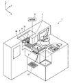
図1は、本実施の形態のパッケージ基板の分割方法が適用される切削装置の一例を示す外観斜視図である。本実施の形態で用いる切削装置1は、概略構成として、図1に示すように、パッケージ基板10を保持するチャックテーブル2と、チャックテーブル2に保持されたパッケージ基板10に対して分割のための切削加工を施す切削手段3と、撮像手段4と、切削装置1による切削加工動作を制御する制御部5とを備える。
FIG. 1 is an external perspective view showing an example of a cutting device to which the package substrate dividing method of the present embodiment is applied. As shown in FIG. 1, the
ここで、切削手段3は、一対の切削ブレード31,32(図2参照)をY軸方向に互いに進退自在に対峙させて2つのスピンドル33,34(図2参照)を配置させたフェイシングデュアルカット方式のものであり、一対の切削ブレード31,32を用いてパッケージ基板10に対して2ライン分の同時カットが可能とされている。すなわち、切削手段3は、一方の切削ブレード31が着脱自在に装着されたスピンドル33と、このスピンドル33を回転可能に支持するとともに回転駆動する図示しない駆動源を含む円筒状のハウジング35と、他方の切削ブレード32が着脱自在に装着されたスピンドル34と、このスピンドル34を回転可能に支持するとともに回転駆動する図示しない駆動源を含む円筒状のハウジング36とを備える。
Here, the cutting means 3 is a facing dual in which a pair of
また、切削装置1は、詳細は特に図示しないが、パッケージ基板10を保持したチャックテーブル2を切削手段3に対して相対的にX軸方向に加工送りする加工送り手段や、切削手段3の切削ブレード31,32を独立してチャックテーブル2に対して相対的にY軸方向に割り出し送り(インデックス送り)する割り出し送り手段や、切削手段3の切削ブレード31,32を独立してチャックテーブル2に保持されたパッケージ基板10に対して相対的にZ軸方向に切り込み送りする切込み送り手段を備える。
Further, although not shown in detail in detail, the
撮像手段4は、チャックテーブル2に保持されたパッケージ基板10の表面を撮像するCCDカメラ等を搭載した顕微鏡であり、切削すべき分割予定ラインに対する切削ブレード31,32の位置付けに供するアライメント用である。
The imaging means 4 is a microscope equipped with a CCD camera or the like that images the surface of the
また、パッケージ基板10を保持するチャックテーブル2は、特に図示しないが、回転手段に連結されて水平面内で回転可能とされている。これにより、保持したパッケージ基板10のX軸方向に対する向きをXY平面内で回動調整可能とされている。
Further, the chuck table 2 that holds the
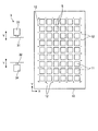
さらに、本実施の形態で切削対象とするパッケージ基板10は、ボール状の端子が裏面から突出した配線基板の表面に1または2以上の半導体チップを積層してボンディングし、さらにボンディングされた半導体チップを樹脂によってモールドすることによって、図2に示すように、1枚の基板として構成されたものである。ここで、パッケージ基板10は、分割予定ライン(ストリート)Sによって複数のCSPチップ等のデバイス11が所定数区画され形成されて細長矩形状に形成されたものである。図2等では、説明を簡単にするために5×9=45個のデバイス11からなり、10本×7本の分割予定ラインSを有する例に単純化して示す。もっとも、パッケージ基板10の、より実際的な構成としては、より多数のデバイス11が区画形成されている。また、パッケージ基板10においては、分割予定ラインS毎にその位置を規定するアライメントパターン12が周囲に形成されている。ここで、パッケージ基板10は、歪みが大きく、アライメントパターン12により規定される各分割予定ラインSの平行精度は低く、互いに平行でない場合がある。
Further, the
制御部5は、切削装置1によるパッケージ基板10の切削に際して、切削手段3、撮像手段4、各送り手段等を制御して、回転可能なチャックテーブル2に保持されたパッケージ基板10の全ての分割予定ラインSの角度θを測定する工程と、測定された各分割予定ラインSの角度θの情報に基づき、角度θのずれ量Δθが予め設定された許容値Δ内に収まる範囲で一対の切削ブレード31,32によって同時に切削する分割予定ライン対を決定する工程と、決定された分割予定ライン対の単位で一対の切削ブレード31,32を順次分割予定ラインSに位置付けて切削する工程と、を実行させる。
The
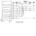
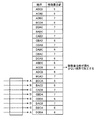
以下、制御部5による制御の下に実行される本実施の形態のパッケージ基板10の分割方法について説明する。まず、図3および図4を参照して、本実施の形態によるパッケージ基板10の分割方法の概要を説明する。図3は、本実施の形態によるパッケージ基板10の分割方法の概要を示す模式図であり、図4は、切削順序を決定するための説明図である。
Hereinafter, a method for dividing the
まず、チャックテーブル2に保持されたパッケージ基板10を撮像手段4で撮像して各アライメントパターン12の位置を検出することで、長手方向の10本の分割予定ラインS1〜S10のX軸方向に対する傾き角度θを撮像手段4によって測定する。ここで、各分割予定ラインS1〜S10の傾き角度θが、図3に示すように、順に、0.6°、3.0°、1.1°、−1.3°、−2.2°、0.9°、−1.8°、−1.1°、0.7°、2.1°であったとする(これらの数値例は、説明の都合上、誇張して示すものであり、実際には、桁違いに小さな数値となる)。
First, the
ついで、傾き角度θのずれ量Δθが、予め設定された許容値Δ内に収まる範囲で、このずれ量Δθが最小となり、一対の切削ブレード31,32で同時に切削する分割予定ライン対Pを決定する。ここで、許容値Δは、例えばΔ=0.8の如く設定されているものとする。すると、このような条件を満たす分割予定ライン対としては、
分割予定ライン対A:分割予定ラインS1,S9(Δθ=0.1)
分割予定ライン対B:分割予定ラインS2,S6(Δθ=0.2)
分割予定ライン対C:分割予定ラインS3,S8(Δθ=0.2)
分割予定ライン対D:分割予定ラインS4,S7(Δθ=0.4)
の如く、決定される。この際、分割予定ラインS2,S10については、他の分割予定ラインとの間における角度のずれ量が許容値Δ=0.8よりも大きくなってしまうため、分割予定ライン対としては決定されず、切削ブレード31,32のいずれか一方によって単独で切削する対象として決定される。
Next, in the range where the deviation amount Δθ of the inclination angle θ falls within the preset allowable value Δ, the deviation amount Δθ is minimized, and the pair of division lines P to be cut simultaneously by the pair of cutting
Scheduled line pair A: Scheduled lines S1, S9 (Δθ = 0.1)
Scheduled line pair B: Scheduled lines S2, S6 (Δθ = 0.2)
Scheduled line pair C: Scheduled lines S3 and S8 (Δθ = 0.2)
Scheduled line pair D: Scheduled lines S4 and S7 (Δθ = 0.4)
It is determined as follows. At this time, regarding the scheduled division lines S2 and S10, the amount of deviation of the angle with the other planned division lines becomes larger than the allowable value Δ = 0.8, so that they are not determined as the planned division line pairs. The object to be cut independently by either one of the
分割予定ライン対の決定後、分割予定ライン対A〜D毎に、対をなす2つの分割予定ラインの傾き角度θの平均値を算出する。図3に示す例であれば、
分割予定ライン対A:角度θの平均値= 0.65
分割予定ライン対B:角度θの平均値= 1.00
分割予定ライン対C:角度θの平均値=−1.20
分割予定ライン対D:角度θの平均値=−2.00
となる。
After determining the division line pairs, the average value of the inclination angles θ of the two division lines forming a pair is calculated for each of the division line pairs A to D. In the example shown in FIG.
Divided line pair A: average value of angle θ = 0.65
Divided line pair B: average value of angle θ = 1.00
Divided line pair C: average value of angle θ = −1.20
Divided line pair D: average value of angle θ = −2.00
It becomes.
ついで、決定された各分割予定ライン対A〜Dに関して、一対の切削ブレード31,32のスピンドル方向(Y軸方向)の移動量(インデックス移動量)が最小となる切削順序を決定する。この切削順序の決定は、例えば、図4に示すように、各分割予定ライン対A〜Dに関する切削順序を入れ替えた場合のそれぞれの移動量の合計を算出し、その移動量合計の最も少ない順序に決定すればよい。例えば、順序ABCDと仮定した場合の移動量合計(1回目移動量+2回目移動量+3回目移動量)は、切削ブレード31のインデックス移動量は、1+1+1=3であり、切削ブレード32の移動量は、3+2+1=6であり、大きい方の移動量6が移動量合計として算出される。他の順序の場合の移動量合計も同様にして算出される。なお、分割予定ライン対を構成しない単独の分割予定ラインS2,S10に関しては、共通なため、移動量合計に関しては無視する。このような移動量合計の結果によれば、順序ACDBの場合が最も移動量の少ない順序となる。よって、切削順序は、分割予定ライン対A→分割予定ライン対C→分割予定ライン対D→分割予定ライン対Bとなり、この後に、単独の分割予定ラインS2→単独の分割予定ラインS10となる。
Next, the cutting order in which the moving amount (index moving amount) in the spindle direction (Y-axis direction) of the pair of cutting
このような切削順序の決定後、分割予定ライン対A〜Dの単位で、かつ、決定された切削順序ACDBに従い、一対の切削ブレード31,32を順次分割予定ラインSに位置付けて切削を行わせる。この際、一対の切削ブレード31,32が分割予定ライン対ACDBのそれぞれ算出された平均値角度の位置に位置付けられるようにチャックテーブル2によってパッケージ基板10を回転させてθ合わせを行う。
After such a cutting order is determined, a pair of cutting
まず、分割予定ライン対Aの分割予定ラインS1に対して切削ブレード31を、分割予定ラインS9に対して切削ブレード32をそれぞれ位置付けるが、これに先立ち、角度θの平均値=0.65がX軸方向と平行となるようにチャックテーブル2によってパッケージ基板10を回転させてθ合わせを行う。そして、スピンドル33,34を高速回転させながら、Z軸方向に切り込み送りさせるとともに、チャックテーブル2をX軸方向に加工送りさせることで、分割予定ラインS1,S9を切削ブレード31,32で同時に切削加工する。
First, the
分割予定ラインS1,S9の切削加工後、切削ブレード31,32をZ軸方向に退避させ、次の分割予定ライン対Cの角度θの平均値=−1.20がX軸方向と平行となるようにチャックテーブル2によってパッケージ基板10を回転させてθ合わせを行う。そして、切削ブレード31,32を分割予定ライン対Cの分割予定ラインS4,S8の位置に対してインデックス送りさせ、スピンドル33,34を高速回転させながら、Z軸方向に切り込み送りさせるとともに、チャックテーブル2をX軸方向に加工送りさせることで、分割予定ラインS4,S8を切削ブレード31,32で同時に切削加工する。
After cutting the scheduled division lines S1 and S9, the
後続の分割予定ライン対D,Bについても同様に、一対の切削ブレード31,32を用いて2ライン分同時に切削加工を行う。そして、最後に、単独の分割予定ラインS2は、例えば切削ブレード31を用いて単独で切削加工を行い、単独の分割予定ラインS10は、例えば切削ブレード32を用いて単独で切削加工を行うことで、一方向の全ての分割予定ラインS1〜S10の切削加工が終了する。
Similarly, with respect to the subsequent divided line pairs D and B, two lines are simultaneously cut using the pair of cutting
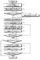
図5は、制御部5により実行されるこのようなパッケージ基板10の分割方法を示す概略フローチャートである。まず、チャックテーブル2上に保持されたパッケージ基板10を撮像手段4の直下に位置付け、パッケージ基板10の表面の各アライメントパターン12を撮像手段4で順次撮像し、各アライメントパターン12のX座標およびY座標を求めることで、各分割予定ラインSの傾き角度θを測定する(ステップS1)。ついで、許容値Δ内で、角度ずれ量Δθが最小のもの同士を、一対の切削ブレード31,32で同時に切削する分割予定ライン対に決定する(ステップS2)。この際、許容値Δ外となる分割予定ラインがあれば(ステップS3;Yes)、そのラインを一方の切削ブレード31または32で切削する単独の分割予定ラインとして決定する(ステップS4)。
FIG. 5 is a schematic flowchart showing such a dividing method of the
ついで、各分割予定ライン対に関して、一対の切削ブレード31,32のスピンドル方向の移動量が最小となるように切削順序を決定する(ステップS5)。さらに、各分割予定ライン対の角度ずれ量の平均値を算出する(ステップS6)。なお、ステップS5,S6の処理順序は、逆でもよい。
Next, the cutting order is determined so that the movement amount in the spindle direction of the pair of cutting
引き続き、決定された分割予定ライン対の切削順序に従い、チャックテーブル2の回転によるパッケージ基板10のθ合わせを行うとともに、一対の切削ブレード31,32をインデックス送りして各分割予定ライン対の角度ずれ量の平均値位置に位置付ける(ステップS7)。そこで、チャックテーブル2をX軸方向に切削送りさせ、分割予定ライン対を構成する2つの分割予定ラインを一対の切削ブレード31,32で同時にデュアルカットする(ステップS8)。このような処理を、切削順序に従い、分割予定ライン対の全ての切削が終了するまで繰り返す(ステップS9)。
Subsequently, in accordance with the determined cutting order of the divided line pairs, θ adjustment of the
分割予定ライン対の切削が終了して(ステップS9;Yes)、単独の分割予定ラインがあれば(ステップS10;Yes)、チャックテーブル2の回転によるパッケージ基板10のθ合わせを行うとともに一方の切削ブレード31または32を単独の分割予定ラインの角度に位置付け(ステップS11)、チャックテーブル2をX軸方向に切削送りさせ、単独の分割予定ラインを切削ブレード31または32でシングルカットする(ステップS12)。このような処理を、単独の分割予定ライン対の全ての切削が終了するまで繰り返す(ステップS13)。
If the cutting of the pair of lines to be divided is completed (step S9; Yes) and there is a single line to be divided (step S10; Yes), θ adjustment of the
このように本実施の形態のパッケージ基板10の分割方法によれば、分割予定ラインS単位で、かつ、角度のずれ量Δθが予め設定された許容値Δ内に収まる範囲内で一対の切削ブレード31,32で同時に切削する分割予定ライン対を決定しているので、デュアルカットによる高スループットを確保しつつ、分割予定ラインS間に角度ずれがあっても分割予定ラインSと実際の切削加工ラインとの間の角度ずれに関して必要最低限の精度を確保した切削加工を行うことができる。特に、許容値Δ内に収まる範囲で決定された分割予定ライン対の傾き角度θを平均化して切削位置を決定しているので、分割予定ラインSと実際の切削加工ラインとのずれ量をさらに高精度化できる。さらには、許容値Δ内であって、分割予定ラインS間の角度のずれ量Δθが最小となるもの同士を分割予定ライン対に決定しているので、デュアルカット時の角度ずれに関する精度を、一層高精度化することができる。さらに、本実施の形態によれば、各分割予定ライン対に関して一対の切削ブレード31,32の移動量が最小となる切削順序を決定し、決定された切削順序に従いデュアルカットを行わせるので、デュアルカットによる切削処理の効率を向上させることもできる。また、許容値Δ内に収まらない分割予定ライン同士は、無理矢理、分割予定ライン対を構成してデュアルカットさせないので、角度ずれが許容値Δ内に収まる切削を確保することができる。
As described above, according to the method for dividing the
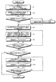
本発明は、上述した実施の形態に限らず、本発明の趣旨を逸脱しない範囲であれば、種々の変形が可能である。例えば、本実施の形態では、分割予定ライン対の決定に際して、ずれ量Δθが最小となるもの同士を分割予定ライン対に決定するようにしたが、許容値Δ内であれば、ずれ量Δθが最小となるもの同士の組み合わせに限らない。例えば、角度のずれ量Δθが予め設定された許容値Δ内に収まる範囲の複数の分割予定ラインのうちで、先行して切削する分割予定ライン対の位置から後行して切削する分割予定ラインの位置までの一対の切削ブレード31,32のスピンドル方向の移動量が最小となるように切削順序を含めて分割予定ライン対を決定するようにしてもよい。
The present invention is not limited to the above-described embodiment, and various modifications can be made without departing from the spirit of the present invention. For example, in the present embodiment, when the planned split line pair is determined, those having the smallest shift amount Δθ are determined as split planned line pairs. However, if within the allowable value Δ, the shift amount Δθ is determined. The combination is not limited to the minimum. For example, among the plurality of scheduled division lines in a range where the angle deviation amount Δθ falls within the preset allowable value Δ, the scheduled division line that is cut after the position of the division planned line pair to be cut first is cut. The pair of lines to be divided may be determined including the cutting order so that the moving amount in the spindle direction of the pair of cutting
図3を参照すれば、図3中に示すような分割予定ライン対A〜Dとしての組合せの他に、例えば、分割予定ライン対E;分割予定ラインS1,S6(角度ずれ量Δθ=0.3)、分割予定ライン対F;分割予定ラインS3,S9(角度ずれ量Δθ=0.4)も想定し、組合せ可能なこれら全ての分割予定ライン対A〜D,C〜Fに関して、図4で説明したような移動量合計を算出し、その移動量が最小となるように切削順序を含めて分割予定ライン対を決定することも可能である。 Referring to FIG. 3, in addition to the combinations as the scheduled division line pairs A to D as shown in FIG. 3, for example, the planned division line pair E; the planned division lines S1 and S6 (angle deviation amount Δθ = 0. 3) Scheduled line pair F; Scheduled lines S3 and S9 (angle deviation amount Δθ = 0.4) are also assumed, and all these scheduled line pairs A to D and C to F that can be combined are shown in FIG. It is also possible to calculate the total amount of movement as described in (1) and determine the division line pair including the cutting order so that the amount of movement is minimized.
図6は、制御部5により実行されるこの場合のパッケージ基板10の分割方法を示す概略フローチャートである。ここでは、図5に示したステップS2の処理に代えて、許容値Δ内で、移動量が最小となるような切削順序を加味して、一対の切削ブレード31,32で同時に切削する分割予定ライン対に決定する処理を行う(ステップS21)。また、ステップS5の処理が省略される。これによれば、デュアルカット時の角度ずれに関する精度を確保しつつ、デュアルカットによる切削処理の効率を向上させることができる。
FIG. 6 is a schematic flowchart showing a method for dividing the
また、本実施の形態では、分割予定ライン対の切削に際して、2つの分割予定ラインの角度の平均値角度の位置に切削ブレード31,32を位置付けるようにしたが、2つの分割予定ラインのいずれか一方の傾き角度の位置に切削ブレード31,32を位置付けてデュアルカットさせても、許容値Δ内のずれ精度を確保することができる。
Further, in the present embodiment, the
また、2つの分割予定ラインの角度の平均値角度を利用する場合であれば、分割予定ライン対を構成するための許容値をΔ/2(図3等の場合であれば、Δ/2=0.4)に狭めて規定するようにしてもよい。これによれば、角度ずれに対する精度を上げることができる。 Further, if the average value of the angles of the two scheduled lines is used, an allowable value for constructing the scheduled line pair is Δ / 2 (in the case of FIG. 3 or the like, Δ / 2 = You may make it prescribe | regulate by narrowing to 0.4). According to this, the precision with respect to an angle shift can be raised.
また、本実施の形態では、CSP基板のようなパッケージ基板10への適用例として説明したが、QFN基板であってもよく、さらには、次世代CSPと称されるウエーハレベルCSP(WL−CSP)等であっても同様に適用可能である。
In this embodiment, the application example to the
1 切削装置
2 チャックテーブル
10 パッケージ基板
11 デバイス
31,32 切削ブレード
33,34 スピンドル
S1〜S10 分割予定ライン
A〜D 分割予定ライン対
DESCRIPTION OF
Claims (5)
回転可能なチャックテーブルに保持された前記パッケージ基板の全ての分割予定ラインの角度を測定する工程と、
測定された各分割予定ラインの角度の情報に基づき、角度のずれ量が予め設定された許容値内に収まる範囲で前記一対の切削ブレードによって同時に切削する分割予定ライン対を決定する工程と、
決定された各分割予定ライン対に関して前記一対の切削ブレードの前記スピンドル方向の移動量が最小となる切削順序を決定する工程と、
決定された分割予定ライン対の単位で前記一対の切削ブレードを順次分割予定ラインに位置付けて切削する工程と、
を備え、
前記切削する工程では、決定された切削順序に従い前記一対の切削ブレードを順次各分割予定ライン対に位置付けて切削することを特徴とするパッケージ基板の分割方法。 A package substrate in which a plurality of devices are partitioned and formed by a predetermined division line, and is divided into individual package devices by using a cutting device in which a pair of cutting blades are opposed to each other so as to be able to move forward and backward. Dividing method,
Measuring the angles of all the division lines of the package substrate held on the rotatable chuck table;
Determining a split line pair to be cut simultaneously by the pair of cutting blades within a range in which the amount of deviation of the angle falls within a preset allowable value, based on the measured angle information of each split line; and
Determining a cutting order that minimizes the amount of movement of the pair of cutting blades in the spindle direction with respect to each determined split line pair;
A step of sequentially positioning the pair of cutting blades in the planned division line in units of the determined division line pair and cutting,
Equipped with a,
In the cutting step, the pair of cutting blades are sequentially positioned on each division line pair and cut in accordance with the determined cutting order .
回転可能なチャックテーブルに保持された前記パッケージ基板の全ての分割予定ラインの角度を測定する工程と、
測定された各分割予定ラインの角度の情報に基づき、角度のずれ量が予め設定された許容値内に収まる範囲で前記一対の切削ブレードによって同時に切削する分割予定ライン対を決定する工程と、
決定された分割予定ライン対の単位で前記一対の切削ブレードを順次分割予定ラインに位置付けて切削する工程と、
を備え、
前記決定する工程では、角度のずれ量が予め設定された許容値内に収まる範囲の複数の分割予定ラインのうちで、先行して切削する分割予定ライン対の位置から後行して切削する分割予定ラインの位置までの前記一対の切削ブレードの前記スピンドル方向の移動量が最小となるように切削順序を含めて分割予定ライン対を決定し、
前記切削する工程では、決定された切削順序に従い前記一対の切削ブレードを順次各分割予定ライン対に位置付けて切削することを特徴とするパッケージ基板の分割方法。 A package substrate in which a plurality of devices are partitioned and formed by a predetermined division line, and is divided into individual package devices by using a cutting device in which a pair of cutting blades are opposed to each other so as to be able to move forward and backward. Dividing method,
Measuring the angles of all the division lines of the package substrate held on the rotatable chuck table;
Determining a split line pair to be cut simultaneously by the pair of cutting blades within a range in which the amount of deviation of the angle falls within a preset allowable value, based on the measured angle information of each split line; and
A step of sequentially positioning the pair of cutting blades in the planned division line in units of the determined division line pair and cutting,
Equipped with a,
In the determining step, of the plurality of division lines within a range in which the angle deviation amount falls within a preset allowable value, the division is performed by cutting from the position of the division line line to be cut in advance. Determine the split line pair including the cutting order so that the movement amount in the spindle direction of the pair of cutting blades to the position of the planned line is minimized,
In the cutting step, the pair of cutting blades are sequentially positioned on each division line pair and cut in accordance with the determined cutting order .
前記切削する工程では、前記一対の切削ブレードが該分割予定ライン対の算出された平均値角度の位置に位置付けられるように前記チャックテーブルによって前記パッケージ基板を回転させることを特徴とする請求項1または2に記載のパッケージ基板の分割方法。 A step of calculating an average value of angles of two division lines to be paired for each determined division line pair,
In the step of the cutting, claim 1 wherein the pair of cutting blades characterized in that rotating the package substrate by the chuck table to be positioned at the position of the average value angle calculated in the dividing line pair or 3. A method for dividing a package substrate according to 2 .
Priority Applications (1)
| Application Number | Priority Date | Filing Date | Title |
|---|---|---|---|
| JP2007216053A JP5127361B2 (en) | 2007-08-22 | 2007-08-22 | Package substrate division method |
Applications Claiming Priority (1)
| Application Number | Priority Date | Filing Date | Title |
|---|---|---|---|
| JP2007216053A JP5127361B2 (en) | 2007-08-22 | 2007-08-22 | Package substrate division method |
Publications (2)
| Publication Number | Publication Date |
|---|---|
| JP2009049303A JP2009049303A (en) | 2009-03-05 |
| JP5127361B2 true JP5127361B2 (en) | 2013-01-23 |
Family
ID=40501231
Family Applications (1)
| Application Number | Title | Priority Date | Filing Date |
|---|---|---|---|
| JP2007216053A Active JP5127361B2 (en) | 2007-08-22 | 2007-08-22 | Package substrate division method |
Country Status (1)
| Country | Link |
|---|---|
| JP (1) | JP5127361B2 (en) |
Families Citing this family (3)
| Publication number | Priority date | Publication date | Assignee | Title |
|---|---|---|---|---|
| JP5645692B2 (en) * | 2011-02-08 | 2014-12-24 | 株式会社ディスコ | Processing method |
| JP6184855B2 (en) * | 2013-12-16 | 2017-08-23 | 株式会社ディスコ | Package substrate division method |
| CN114549560B (en) * | 2022-03-02 | 2025-02-14 | 科为升视觉技术(苏州)有限公司 | A chip cutting route calculation method, system and readable storage medium |
Family Cites Families (6)
| Publication number | Priority date | Publication date | Assignee | Title |
|---|---|---|---|---|
| JP3666068B2 (en) * | 1995-08-10 | 2005-06-29 | 株式会社ディスコ | Cutting method |
| JP4640715B2 (en) * | 2000-07-14 | 2011-03-02 | 株式会社ディスコ | Alignment method and alignment apparatus |
| JP2002237472A (en) * | 2001-02-07 | 2002-08-23 | Disco Abrasive Syst Ltd | Workpiece cutting method |
| JP4436641B2 (en) * | 2003-09-09 | 2010-03-24 | 株式会社ディスコ | Alignment method in cutting equipment |
| JP2005286159A (en) * | 2004-03-30 | 2005-10-13 | Sodick Co Ltd | Method for cutting work and cutting apparatus |
| JP4522234B2 (en) * | 2004-11-17 | 2010-08-11 | 株式会社ディスコ | Panel cutting method |
-
2007
- 2007-08-22 JP JP2007216053A patent/JP5127361B2/en active Active
Also Published As
| Publication number | Publication date |
|---|---|
| JP2009049303A (en) | 2009-03-05 |
Similar Documents
| Publication | Publication Date | Title |
|---|---|---|
| JP4640715B2 (en) | Alignment method and alignment apparatus | |
| US9396976B2 (en) | Cutting apparatus | |
| JP6282194B2 (en) | Wafer processing method | |
| JP5187505B2 (en) | Dicing method | |
| JP2009170501A (en) | Cutting equipment | |
| JP5214332B2 (en) | Wafer cutting method | |
| JP6845038B2 (en) | How to divide the package board | |
| JP6257291B2 (en) | Processing method of package substrate | |
| JP6482618B2 (en) | Processing apparatus and processing method | |
| TWI431677B (en) | Segmentation method of packaging substrate | |
| JP5762005B2 (en) | Processing position adjustment method and processing apparatus | |
| JP2016153154A (en) | Wafer positioning method | |
| JP6229883B2 (en) | Dicing apparatus and cutting method thereof | |
| JP5127361B2 (en) | Package substrate division method | |
| JP5709593B2 (en) | Processing equipment | |
| JP2012151225A (en) | Method for measuring cut groove | |
| JP5393587B2 (en) | Alignment method for singulation system | |
| CN104716093B (en) | Dividing method of package substrate | |
| JP4436641B2 (en) | Alignment method in cutting equipment | |
| JP5645692B2 (en) | Processing method | |
| JP2004241686A (en) | Alignment method and alignment device | |
| JP2007253289A (en) | Drop-proof mechanism of work table, and wire saw | |
| JP6037705B2 (en) | Workpiece processing method | |
| JP4645844B2 (en) | Multi-type wire saw and processing method using wire saw | |
| CN106098622A (en) | Manufacture device and manufacture method and the system of manufacture |
Legal Events
| Date | Code | Title | Description |
|---|---|---|---|
| A621 | Written request for application examination |
Free format text: JAPANESE INTERMEDIATE CODE: A621 Effective date: 20100713 |
|
| A977 | Report on retrieval |
Free format text: JAPANESE INTERMEDIATE CODE: A971007 Effective date: 20120531 |
|
| A131 | Notification of reasons for refusal |
Free format text: JAPANESE INTERMEDIATE CODE: A131 Effective date: 20120605 |
|
| A521 | Request for written amendment filed |
Free format text: JAPANESE INTERMEDIATE CODE: A523 Effective date: 20120723 |
|
| TRDD | Decision of grant or rejection written | ||
| A01 | Written decision to grant a patent or to grant a registration (utility model) |
Free format text: JAPANESE INTERMEDIATE CODE: A01 Effective date: 20121016 |
|
| A01 | Written decision to grant a patent or to grant a registration (utility model) |
Free format text: JAPANESE INTERMEDIATE CODE: A01 |
|
| A61 | First payment of annual fees (during grant procedure) |
Free format text: JAPANESE INTERMEDIATE CODE: A61 Effective date: 20121030 |
|
| R150 | Certificate of patent or registration of utility model |
Ref document number: 5127361 Country of ref document: JP Free format text: JAPANESE INTERMEDIATE CODE: R150 Free format text: JAPANESE INTERMEDIATE CODE: R150 |
|
| FPAY | Renewal fee payment (event date is renewal date of database) |
Free format text: PAYMENT UNTIL: 20151109 Year of fee payment: 3 |
|
| FPAY | Renewal fee payment (event date is renewal date of database) |
Free format text: PAYMENT UNTIL: 20151109 Year of fee payment: 3 |
|
| R250 | Receipt of annual fees |
Free format text: JAPANESE INTERMEDIATE CODE: R250 |
|
| R250 | Receipt of annual fees |
Free format text: JAPANESE INTERMEDIATE CODE: R250 |
|
| R250 | Receipt of annual fees |
Free format text: JAPANESE INTERMEDIATE CODE: R250 |
|
| R250 | Receipt of annual fees |
Free format text: JAPANESE INTERMEDIATE CODE: R250 |
|
| R250 | Receipt of annual fees |
Free format text: JAPANESE INTERMEDIATE CODE: R250 |
|
| R250 | Receipt of annual fees |
Free format text: JAPANESE INTERMEDIATE CODE: R250 |
|
| R250 | Receipt of annual fees |
Free format text: JAPANESE INTERMEDIATE CODE: R250 |
|
| R250 | Receipt of annual fees |
Free format text: JAPANESE INTERMEDIATE CODE: R250 |
|
| R250 | Receipt of annual fees |
Free format text: JAPANESE INTERMEDIATE CODE: R250 |
|
| R250 | Receipt of annual fees |
Free format text: JAPANESE INTERMEDIATE CODE: R250 |
|
| R250 | Receipt of annual fees |
Free format text: JAPANESE INTERMEDIATE CODE: R250 |