JP5097941B2 - Cord armor with movable die - Google Patents
Cord armor with movable die Download PDFInfo
- Publication number
- JP5097941B2 JP5097941B2 JP2007217605A JP2007217605A JP5097941B2 JP 5097941 B2 JP5097941 B2 JP 5097941B2 JP 2007217605 A JP2007217605 A JP 2007217605A JP 2007217605 A JP2007217605 A JP 2007217605A JP 5097941 B2 JP5097941 B2 JP 5097941B2
- Authority
- JP
- Japan
- Prior art keywords
- die
- central chamber
- cord
- movable die
- section
- Prior art date
- Legal status (The legal status is an assumption and is not a legal conclusion. Google has not performed a legal analysis and makes no representation as to the accuracy of the status listed.)
- Expired - Fee Related
Links
Images


Classifications
-
- B—PERFORMING OPERATIONS; TRANSPORTING
- B29—WORKING OF PLASTICS; WORKING OF SUBSTANCES IN A PLASTIC STATE IN GENERAL
- B29D—PRODUCING PARTICULAR ARTICLES FROM PLASTICS OR FROM SUBSTANCES IN A PLASTIC STATE
- B29D30/00—Producing pneumatic or solid tyres or parts thereof
- B29D30/06—Pneumatic tyres or parts thereof (e.g. produced by casting, moulding, compression moulding, injection moulding, centrifugal casting)
- B29D30/38—Textile inserts, e.g. cord or canvas layers, for tyres; Treatment of inserts prior to building the tyre
-
- B—PERFORMING OPERATIONS; TRANSPORTING
- B29—WORKING OF PLASTICS; WORKING OF SUBSTANCES IN A PLASTIC STATE IN GENERAL
- B29C—SHAPING OR JOINING OF PLASTICS; SHAPING OF MATERIAL IN A PLASTIC STATE, NOT OTHERWISE PROVIDED FOR; AFTER-TREATMENT OF THE SHAPED PRODUCTS, e.g. REPAIRING
- B29C48/00—Extrusion moulding, i.e. expressing the moulding material through a die or nozzle which imparts the desired form; Apparatus therefor
- B29C48/03—Extrusion moulding, i.e. expressing the moulding material through a die or nozzle which imparts the desired form; Apparatus therefor characterised by the shape of the extruded material at extrusion
- B29C48/05—Filamentary, e.g. strands
-
- B—PERFORMING OPERATIONS; TRANSPORTING
- B29—WORKING OF PLASTICS; WORKING OF SUBSTANCES IN A PLASTIC STATE IN GENERAL
- B29C—SHAPING OR JOINING OF PLASTICS; SHAPING OF MATERIAL IN A PLASTIC STATE, NOT OTHERWISE PROVIDED FOR; AFTER-TREATMENT OF THE SHAPED PRODUCTS, e.g. REPAIRING
- B29C48/00—Extrusion moulding, i.e. expressing the moulding material through a die or nozzle which imparts the desired form; Apparatus therefor
- B29C48/03—Extrusion moulding, i.e. expressing the moulding material through a die or nozzle which imparts the desired form; Apparatus therefor characterised by the shape of the extruded material at extrusion
- B29C48/06—Rod-shaped
-
- B—PERFORMING OPERATIONS; TRANSPORTING
- B29—WORKING OF PLASTICS; WORKING OF SUBSTANCES IN A PLASTIC STATE IN GENERAL
- B29C—SHAPING OR JOINING OF PLASTICS; SHAPING OF MATERIAL IN A PLASTIC STATE, NOT OTHERWISE PROVIDED FOR; AFTER-TREATMENT OF THE SHAPED PRODUCTS, e.g. REPAIRING
- B29C48/00—Extrusion moulding, i.e. expressing the moulding material through a die or nozzle which imparts the desired form; Apparatus therefor
- B29C48/03—Extrusion moulding, i.e. expressing the moulding material through a die or nozzle which imparts the desired form; Apparatus therefor characterised by the shape of the extruded material at extrusion
- B29C48/07—Flat, e.g. panels
- B29C48/08—Flat, e.g. panels flexible, e.g. films
-
- B—PERFORMING OPERATIONS; TRANSPORTING
- B29—WORKING OF PLASTICS; WORKING OF SUBSTANCES IN A PLASTIC STATE IN GENERAL
- B29C—SHAPING OR JOINING OF PLASTICS; SHAPING OF MATERIAL IN A PLASTIC STATE, NOT OTHERWISE PROVIDED FOR; AFTER-TREATMENT OF THE SHAPED PRODUCTS, e.g. REPAIRING
- B29C48/00—Extrusion moulding, i.e. expressing the moulding material through a die or nozzle which imparts the desired form; Apparatus therefor
- B29C48/03—Extrusion moulding, i.e. expressing the moulding material through a die or nozzle which imparts the desired form; Apparatus therefor characterised by the shape of the extruded material at extrusion
- B29C48/13—Articles with a cross-section varying in the longitudinal direction, e.g. corrugated pipes
-
- B—PERFORMING OPERATIONS; TRANSPORTING
- B29—WORKING OF PLASTICS; WORKING OF SUBSTANCES IN A PLASTIC STATE IN GENERAL
- B29C—SHAPING OR JOINING OF PLASTICS; SHAPING OF MATERIAL IN A PLASTIC STATE, NOT OTHERWISE PROVIDED FOR; AFTER-TREATMENT OF THE SHAPED PRODUCTS, e.g. REPAIRING
- B29C48/00—Extrusion moulding, i.e. expressing the moulding material through a die or nozzle which imparts the desired form; Apparatus therefor
- B29C48/25—Component parts, details or accessories; Auxiliary operations
- B29C48/30—Extrusion nozzles or dies
- B29C48/32—Extrusion nozzles or dies with annular openings, e.g. for forming tubular articles
- B29C48/325—Extrusion nozzles or dies with annular openings, e.g. for forming tubular articles being adjustable, i.e. having adjustable exit sections
-
- B—PERFORMING OPERATIONS; TRANSPORTING
- B29—WORKING OF PLASTICS; WORKING OF SUBSTANCES IN A PLASTIC STATE IN GENERAL
- B29C—SHAPING OR JOINING OF PLASTICS; SHAPING OF MATERIAL IN A PLASTIC STATE, NOT OTHERWISE PROVIDED FOR; AFTER-TREATMENT OF THE SHAPED PRODUCTS, e.g. REPAIRING
- B29C48/00—Extrusion moulding, i.e. expressing the moulding material through a die or nozzle which imparts the desired form; Apparatus therefor
- B29C48/25—Component parts, details or accessories; Auxiliary operations
- B29C48/30—Extrusion nozzles or dies
- B29C48/32—Extrusion nozzles or dies with annular openings, e.g. for forming tubular articles
- B29C48/34—Cross-head annular extrusion nozzles, i.e. for simultaneously receiving moulding material and the preform to be coated
-
- B—PERFORMING OPERATIONS; TRANSPORTING
- B29—WORKING OF PLASTICS; WORKING OF SUBSTANCES IN A PLASTIC STATE IN GENERAL
- B29K—INDEXING SCHEME ASSOCIATED WITH SUBCLASSES B29B, B29C OR B29D, RELATING TO MOULDING MATERIALS OR TO MATERIALS FOR MOULDS, REINFORCEMENTS, FILLERS OR PREFORMED PARTS, e.g. INSERTS
- B29K2021/00—Use of unspecified rubbers as moulding material
-
- B—PERFORMING OPERATIONS; TRANSPORTING
- B29—WORKING OF PLASTICS; WORKING OF SUBSTANCES IN A PLASTIC STATE IN GENERAL
- B29K—INDEXING SCHEME ASSOCIATED WITH SUBCLASSES B29B, B29C OR B29D, RELATING TO MOULDING MATERIALS OR TO MATERIALS FOR MOULDS, REINFORCEMENTS, FILLERS OR PREFORMED PARTS, e.g. INSERTS
- B29K2101/00—Use of unspecified macromolecular compounds as moulding material
- B29K2101/12—Thermoplastic materials
-
- B—PERFORMING OPERATIONS; TRANSPORTING
- B29—WORKING OF PLASTICS; WORKING OF SUBSTANCES IN A PLASTIC STATE IN GENERAL
- B29K—INDEXING SCHEME ASSOCIATED WITH SUBCLASSES B29B, B29C OR B29D, RELATING TO MOULDING MATERIALS OR TO MATERIALS FOR MOULDS, REINFORCEMENTS, FILLERS OR PREFORMED PARTS, e.g. INSERTS
- B29K2105/00—Condition, form or state of moulded material or of the material to be shaped
- B29K2105/06—Condition, form or state of moulded material or of the material to be shaped containing reinforcements, fillers or inserts
- B29K2105/08—Condition, form or state of moulded material or of the material to be shaped containing reinforcements, fillers or inserts of continuous length, e.g. cords, rovings, mats, fabrics, strands or yarns
-
- B—PERFORMING OPERATIONS; TRANSPORTING
- B29—WORKING OF PLASTICS; WORKING OF SUBSTANCES IN A PLASTIC STATE IN GENERAL
- B29L—INDEXING SCHEME ASSOCIATED WITH SUBCLASS B29C, RELATING TO PARTICULAR ARTICLES
- B29L2030/00—Pneumatic or solid tyres or parts thereof
- B29L2030/003—Plies; Breakers
- B29L2030/004—Carcasses
-
- B—PERFORMING OPERATIONS; TRANSPORTING
- B29—WORKING OF PLASTICS; WORKING OF SUBSTANCES IN A PLASTIC STATE IN GENERAL
- B29L—INDEXING SCHEME ASSOCIATED WITH SUBCLASS B29C, RELATING TO PARTICULAR ARTICLES
- B29L2031/00—Other particular articles
- B29L2031/34—Electrical apparatus, e.g. sparking plugs or parts thereof
- B29L2031/3462—Cables
-
- Y—GENERAL TAGGING OF NEW TECHNOLOGICAL DEVELOPMENTS; GENERAL TAGGING OF CROSS-SECTIONAL TECHNOLOGIES SPANNING OVER SEVERAL SECTIONS OF THE IPC; TECHNICAL SUBJECTS COVERED BY FORMER USPC CROSS-REFERENCE ART COLLECTIONS [XRACs] AND DIGESTS
- Y10—TECHNICAL SUBJECTS COVERED BY FORMER USPC
- Y10T—TECHNICAL SUBJECTS COVERED BY FORMER US CLASSIFICATION
- Y10T152/00—Resilient tires and wheels
- Y10T152/10—Tires, resilient
Landscapes
- Engineering & Computer Science (AREA)
- Mechanical Engineering (AREA)
- Manufacturing & Machinery (AREA)
- Textile Engineering (AREA)
- Extrusion Moulding Of Plastics Or The Like (AREA)
- Tyre Moulding (AREA)
- Insulated Conductors (AREA)
- Flexible Shafts (AREA)
- Processing Of Terminals (AREA)
- Manufacturing Of Electric Cables (AREA)
- Ropes Or Cables (AREA)
Abstract
Description
本発明は、糸状要素をプラスチック又は熱可塑性材料で被覆する分野に関し、特に、ゴム又は熱可塑性材料の配合物によるコードの外装に関する。 The present invention relates to the field of coating threadlike elements with plastics or thermoplastic materials, and in particular to the sheathing of cords with blends of rubber or thermoplastic materials.
「コード」という用語は、織物製(テキスタイル)であるにせよ金属製であるにせよ、いずれにせよ、たった1本又は数本のストランドを束ねて単一の一体形コードを形成して構成された糸状要素を意味するものと理解されたい。コードは、織物製又は金属製ケーブルと呼ぶこともできる。 The term “cord” is made up of only one or several strands bundled to form a single integral cord, whether it is made of textile (textile) or metal. It should be understood to mean a thread-like element. The cord can also be referred to as a woven or metal cable.
ケーブル外装装置は、一般に、コードがこの装置にいったん入るとコードを案内する手段と、コードの移動方向に垂直に差し向けられたダクトによって、プラスチック又は熱可塑性材料を粘性状態で加圧下で送り出すことができる押出し手段に連結されていて、内部で混合物が圧力下でこのコードを被覆する中央チャンバと、所与の較正断面の押出しダイとを有している。 Cable sheathing devices generally deliver plastic or thermoplastic material under pressure in a viscous state by means of guiding the cord once it enters the device and a duct oriented perpendicular to the direction of cord movement. A central chamber in which the mixture coats the cord under pressure and an extrusion die of a given calibration cross section.
材料は、中央チャンバの高さ位置でコードの表面上に堆積される。コードは、その運動により、外装材料を出口ダイに向かって引っ張り、出口ダイの較正断面は、コードにその最終断面の形状を与える。 Material is deposited on the surface of the cord at the height of the central chamber. The cord, due to its movement, pulls the sheath material toward the exit die, and the calibration cross section of the exit die gives the cord the shape of its final cross section.
被覆一体形コードの製作のためのこの種の装置は、一例として国際公開第93/15896号パンフレットに記載されている。同一平面内に互いに並んで且つ平行に配置されたコードのプライを粘性材料で被覆して被覆コードのストリップを得るための類似の装置も知られている。 An apparatus of this kind for the production of a coated integral cord is described by way of example in WO 93/15896. Similar devices are also known for coating coated cord plies, which are arranged side by side in parallel in the same plane, with a viscous material to obtain a strip of coated cords.
かかる装置の性状に関連した公知の問題は、出現断面の制御に関する。事実、被着されたゴムの品質、その結果としての外装コードの直径は、一定圧力レベルが中央チャンバ内に維持されている場合に速度の増大につれて減少することが分かっている。この速度による効果は、コードによる材料の同伴に関連している。 A known problem associated with the properties of such devices relates to the control of the appearance cross section. In fact, it has been found that the quality of the applied rubber and the resulting outer cord diameter decreases with increasing speed when a constant pressure level is maintained in the central chamber. The effect of this speed is related to the entrainment of material by the cord.
したがって、外装材の断面は、較正ダイの断面Sよりも極めて小さい。かくして、コードの移動速度を増大させる場合に外装材の外面を一定に保つためには中央チャンバ内の圧力を増大させることが必要である。 Therefore, the cross-section of the exterior material is much smaller than the cross-section S of the calibration die. Thus, it is necessary to increase the pressure in the central chamber in order to keep the outer surface of the exterior material constant when increasing the moving speed of the cord.
この問題は、例示目的で言えば、米国特許5,169,547号明細書に記載されており、この米国特許明細書は、押出しスクリュの回転速度又はコードの移動速度に左右することにより直径を制御する装置を開示している。独国特許出願公開第2457249号明細書は、コードを1種類又は2種類以上の材料皮膜で交互に外装することができる2つの同軸ダイキャップを有する装置を開示している。特開昭60−110422号公報は、コード案内手段の軸方向位置を変更することにより中央チャンバ内の圧力を調整することができる装置を開示している。 This problem is described, for illustrative purposes, in US Pat. No. 5,169,547, which determines the diameter by depending on the rotational speed of the extrusion screw or the speed of movement of the cord. An apparatus for controlling is disclosed. German Offenlegungsschrift 2,457,249 discloses a device with two coaxial die caps that can be used to alternately coat a cord with one or more coatings of material. Japanese Patent Application Laid-Open No. 60-110422 discloses an apparatus capable of adjusting the pressure in the central chamber by changing the axial position of the code guiding means.
しかしながら、これら制御手段は、小さな厚さの外装材を得ることが望ましい場合には作用効果が制限されており、これらのうち、外装速度の増大の問題に取り組んでいるものはない。 However, these control means are limited in operation and effect when it is desirable to obtain an exterior material with a small thickness, and none of them address the problem of increased exterior speed.
事実、出口ダイの小さな較正外面と関連した圧力降下により、上述した速度関連効果を減少させるためには、中央チャンバ内の圧力が非常に高いレベルまで必然的に増大することになる。 In fact, the pressure drop associated with the small calibration exterior of the exit die will inevitably increase the pressure in the central chamber to a very high level in order to reduce the speed related effects described above.
この場合、広い動作範囲にわたり圧力を調節することができる装置を提供することが望ましく、これにより、外装装置におけるコード移動速度の変動の振幅を増大させることが望ましい場合には、複雑さ及びコストが増大する。 In this case, it would be desirable to provide a device that can regulate pressure over a wide operating range, which increases the complexity and cost if it is desired to increase the amplitude of fluctuations in the cord travel speed in the exterior device. Increase.
本発明の目的は、かかる問題の基本的な解決策を提供することにある。 The object of the present invention is to provide a basic solution to such a problem.
本発明によれば、1本又は2本以上のコードをプラスチック又は熱可塑性材料で外装するコード外装装置は、装置の入口のところに配置されていて、ダクトによって、材料を粘性状態で圧力下で送り出すことができる押出し手段に連結された中央チャンバに通じるコード案内手段と、外装されたコードのための所与の較正断面S1の出口ダイとを有する。 According to the present invention, a cord sheathing device for sheathing one or more cords with plastic or thermoplastic material is arranged at the entrance of the device, and the duct causes the material to be in a viscous state under pressure. It has a cord guide device leading to linked central chamber to extrusion means that can be delivered, and an outlet die of given calibration section S 1 for the outer code.
コード外装装置は、較正断面S1よりも小さな較正断面S2を備えた少なくとも1つの可動ダイを更に有する。この可動ダイは、アクチュエータによってコードの移動方向に動かされ、アクチュエータは、中央チャンバを貫通しており、アクチュエータは、中央チャンバを可動ダイの内部空間に連通させることができる通路を有する。かくして、コード外装装置が、作動中の場合、アクチュエータは、可動ダイを、可動ダイが中央チャンバと出口ダイとの間で中央チャンバから見て下流側に位置し、中央チャンバから来た材料の流れ全体が、アクチュエータの通路に入った後に可動ダイを通って流れることができるようにする第1の位置と、可動ダイが、中央チャンバと案内手段との間で中央チャンバから見て上流側に位置し、中央チャンバから来た材料の流れ全体が、出口ダイを通って流れることができるようにする第2の位置との間で移動させる。 The cord sheathing device further comprises at least one movable die with a calibration cross section S 2 that is smaller than the calibration cross section S 1 . The movable die is moved in the direction of movement of the cord by the actuator, the actuator passes through the central chamber, and the actuator has a passage that allows the central chamber to communicate with the interior space of the movable die. Thus, when the cord sheathing device is in operation, the actuator moves the movable die between the central chamber and the exit die when the movable die is located downstream from the central chamber and the material flow coming from the central chamber. A first position allowing the whole to flow through the movable die after entering the passage of the actuator, and the movable die is located upstream from the central chamber between the central chamber and the guiding means And the entire flow of material coming from the central chamber is moved between a second position that allows it to flow through the exit die.
本発明の別の目的は、この装置の使用と関連した方法であって、出口ダイの較正断面S1よりも小さな較正断面S2を備えた可動ダイを、コードが低速で動いているとき、中央チャンバと出口ダイとの間に配置し、可動ダイを、コードが高速で動いているとき、中央チャンバから見て上流側に移動させることを特徴とする方法を提供することにある。 Another object of the present invention is a method associated with the use of this device, a movable die with a small calibration section S 2 than the calibration section S 1 of the outlet die when the cord is moving at low speed, An object of the present invention is to provide a method which is disposed between a central chamber and an outlet die, and wherein the movable die is moved upstream as viewed from the central chamber when the cord is moving at high speed.
低速では、コードが材料を同伴する速度の効果は僅かであり、この場合、較正断面は小さいものであるのが良く、このようにことは、可動ダイを中央チャンバと出口ダイとの間で中央チャンバから見て下流側に設けることによって得られる。 At low speeds, the effect of the speed at which the cord entrains the material is negligible, in which case the calibration cross section should be small, and this allows the movable die to be centered between the central chamber and the exit die. It is obtained by providing downstream from the chamber.
中央チャンバ内に入れられている圧力下の材料をコードFに接触させ、材料の外装を所望の断面を備えた状態で可動ダイの較正断面の高さ位置に形成する。 The material under pressure contained in the central chamber is brought into contact with the code F, and the sheath of material is formed at the height of the calibration section of the movable die with the desired section.
上述したように、コードの周りに形成される外装材の断面は、可動ダイの較正断面よりも僅かに小さく、その結果又、出口ダイの断面よりも小さい。かくして、低速では、出口ダイは、可動ダイの高さ位置に形成された外装材のプロフィールに影響を及ぼすことはない。 As mentioned above, the cross-section of the exterior material formed around the cord is slightly smaller than the calibration cross-section of the movable die and, as a result, also smaller than the cross-section of the exit die. Thus, at low speed, the exit die does not affect the profile of the cladding formed at the height of the movable die.
高速では、可動ダイを中央チャンバから上流側に動かし、この可動ダイは、この場合、外装材の形成に役割を果たさず、外装材の特性は、較正断面が可動ダイの較正断面よりも大きな出口ダイによって与えられる。上述した速度の効果と関連のある直径の増大は、大きく、一定の外装断面を維持するためには、中央チャンバ内の圧力を速度について用いられる制御範囲と同一の制御範囲内に維持した状態で調節するのが良い。したがって、コードの移動速度を増大させると、中央チャンバ内の圧力を増大させる必要はもはやない。 At high speed, the movable die is moved upstream from the central chamber, which in this case does not play a role in the formation of the exterior material, and the properties of the exterior material are such that the calibration cross section is larger than the calibration cross section of the movable die. Given by the die. The increase in diameter associated with the speed effect described above is large, with the pressure in the central chamber maintained within the same control range used for speed to maintain a constant exterior cross section. It is good to adjust. Thus, increasing the cord travel speed no longer requires increasing the pressure in the central chamber.
したがって、この装置により、コードを広い速度範囲にわたり粘性状態のプラスチック又は熱可塑性材料で外装できる。さらに、システムの性能は、厚さの小さな外装材を生じさせることが望ましい場合に特に良好である。 Thus, with this device, the cord can be sheathed with a viscous plastic or thermoplastic material over a wide speed range. In addition, the performance of the system is particularly good when it is desirable to produce an exterior material with a small thickness.
本発明の好ましい実施形態は、図1〜図7に示されている。 A preferred embodiment of the present invention is shown in FIGS.
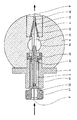
図1は、本発明の外装装置を示している。この装置は、ダクトにより押出し手段(図示せず)に連結された中央チャンバ51を包囲している本体5を有する。押出し手段の機能は、中央チャンバに圧力下で粘性状態のプラスチック又は熱可塑性材料を供給することにある。これら手段は、スリーブ内に配置されたスクリュを有する押し出し機により全く従来の仕方で形成されるのが良く、スクリュの回転速度は、流量及び圧力を決定する。スクリュは又、材料の可塑性及び粘性に作用してコードを外装するための最適な特性を持つ材料を中央チャンバに送り出すよう設計されているのが良い。
FIG. 1 shows an exterior device of the present invention. This device has a
また、材料を圧力下で送り出すことができる他の押出し手段、例えば歯車又はピストンタイプの容積型ポンプを用いることが可能である。 It is also possible to use other extrusion means that can deliver the material under pressure, for example gear or piston type positive displacement pumps.
本発明の目的を達成する装置は、織物又は金属製コード又はケーブルをゴム材料で外装するよう特に設計されている。しかしながら、注目されるべきこととして、必要な改変が用いられる材料の特性に対して行われることを条件として、本発明の装置及び方法は、外装作業に適するようにする粘性特性を持つ任意他の形式の材料でコードを外装するのにもちょうど同様に利用できる。かくして、コードを熱可塑性材料で外装するためには、この材料の熱的比特性を考慮に入れてこの材料を所望の粘性条件下で中央チャンバに送り出すことができるようにすることが必要であろう。 The device that achieves the objectives of the present invention is specifically designed to sheath a fabric or metal cord or cable with a rubber material. However, it should be noted that the apparatus and method of the present invention may be any other having a viscous property that makes it suitable for exterior work, provided that the necessary modifications are made to the properties of the material used. It can be used just as well to arm the cord with a form of material. Thus, in order to sheath the cord with a thermoplastic material, it is necessary to take into account the thermal specific properties of the material so that it can be delivered to the central chamber under the desired viscous conditions. Let's go.
コードFは、本体5を一方の側から他方の側まで横断しており、このコードは、矢印の方向に所与の速度で動き、コード案内2、中央チャンバ51、及び出口ダイ4を連続して通過する。
The cord F traverses the
コード案内2は、それ自体多数本のねじ(図示せず)により本体5にしっかりと取り付けられた支持体3に取り付けられている。コード案内の機能は、コードを中央チャンバの入口のところに心出しすると共にこの中央チャンバ内に存在する圧力下のゴムが案内装置内に入り込むのを阻止することにある。
The
コード案内は、図3及び図6に示されているように、ねじ山22内に挿入された2本のねじ23により支持体上に保持されている。参考までに述べると、コード案内の出口21の断面は、コードの断面に約0.03ミリメートルだけ加えた値に本質的に等しい。また、上述した速度の効果が、コードの断面とコード案内の出口断面との間の僅かな差と組み合わさって、好ましくは、中央チャンバ内のゴムが案内装置を通って出るのを阻止するよう作用する。
The code guide is held on the support by two
可動ダイ12は、図1において、中央チャンバ51から見て下流側に且つ出口ダイ4から見て上流側に位置する「低速」形態で示されている。実際には、可動ダイ12の形状及び出口ダイ4の形状は、2つのダイが互いに嵌まり合って組立体の嵩を減少させるようになっている。
The
出口ダイ4は、本体5に対して固定されている。
The exit die 4 is fixed with respect to the
コードの表面は、中央チャンバ51の高さ位置のところで被覆され、シースの最終断面の形状は、可動ダイ12の下流側部分11の較正断面S2によって与えられる。
The surface of the cord is coated at the height of the
例示の目的で、断面Sが円形の場合、即ち、外装一体形コードを得ることが望ましい場合、断面S1と断面S2の直径の差は、0.1ミリメートル〜0.2ミリメートルのオーダーのものである。速度範囲は、0〜8m/sまで様々であって良く、厚さが0.1ミリメートルの層を形成するゴム材料をコードの表面上に被着させることが望ましい場合、圧力範囲を1MPaから20MPaまで容易に調節することができる。 For illustrative purposes, if the cross-section S is a circle, i.e., when it is desired to obtain an exterior integral code, the difference in diameter cross-section S 1 and cross section S 2 is of 0.1 mm to 0.2 mm in order Is. The speed range may vary from 0 to 8 m / s, and if it is desired to deposit a rubber material forming a 0.1 millimeter thick layer on the surface of the cord, the pressure range is from 1 MPa to 20 MPa. Can be easily adjusted up to.
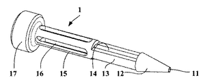
可動ダイ12は、可動ダイ12の後側部分に連結されたアクチュエータによって動かされる。アクチュエータは、中央チャンバ51及び支持体3を貫通しており、このアクチュエータは、図4に示すように前側部分13、中間部分15、及びヘッド17を有している。
The
アクチュエータの前側部分13は、材料を中央チャンバ51から可動ダイの内容積部に循環させることができる通路14を有し、装置が動作していて、可動ダイが「低速」形態に位置決めされているとき、コードFは、この通路を通る。
The
アクチュエータの中間部分15は、支持体3内で且つコード案内2の回りに自由に摺動する。これを可能にするため、長手方向スロット16が、この部分15に沿って全体にわたって作られていて、コード案内2を支持体3に取り付けられた固定位置に保つよう設計されたねじ23を通すことができるようになっている。
The
アクチュエータの後側部分は、作動機構体(図示せず)、例えば空気圧若しくは油圧ジャッキ又は電気アクチュエータ、例えばリニアモータに連結されるよう設計されたヘッド17を有している。
The rear part of the actuator has a
本発明によれば、アクチュエータは、可動ダイ12から見て上流側に配置されている。アクチュエータは、可動ダイから見て下流側に位置決めしても良く、或いは、それどころか、可動ダイを動かすことができる1組の摺動要素を設計して中央チャンバの壁の側方部分に設けても良いことは、注目されるべきである。
According to the present invention, the actuator is disposed upstream from the
図5に示すように2つのシェル半部41,42で形成されたスクレーパ4が、支持体の前側部分に設けられている。スクレーパの形状は、アクチュエータの前側部分13の外側断面の形状に一致するよう設計されている。スクレーパの目的は、コード案内が設けられていて、アクチュエータは中央チャンバからその上流側の位置と下流側位置との間で変位しているときに入る支持体の部分内への材料の侵入を阻止することにある。
As shown in FIG. 5, a
アクチュエータ付きの可動ダイ12、コード案内2、及びスクレーパ41,42を含む支持体3を有する組立体の略図が、図6では斜視図で示され、図7では断面図で示されている。
A schematic diagram of an assembly having a
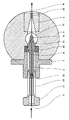
図2は、外装装置をいわゆる「高速」形態で示している。可動ダイ12は、装置内で上流側に動かされ、可動ダイの内側部分は、中央チャンバ51の内部空間を越えてコア案内の端部の周りに嵌まり、この内部空間は、この場合、出口ダイ4の内部と直接連通している。可動ダイ12は、無力化されている。
FIG. 2 shows the exterior device in the so-called “high speed” form. The
コードの較正は、出口ダイ4の下流側部分41の高さ位置で行われ、出口ダイの断面S2は、可動ダイの断面S1よりも大きい。
Calibration of the code is performed at the level of the
本明細書で説明している装置は、単一の可動ダイ12及び1つの出口ダイ4を有している。また、本発明の範囲から逸脱しないで、数個の可動ダイをコードの移動方向に沿って且つ出口ダイから見て上流側に配置することが可能であり、この出口ダイの較正断面S1は、次第に減少する。このより複雑な構成は、粘性の高い材料を用いることにより生じる問題又は非常に薄い外層材の製造と関連した問題を解決することができる。
The apparatus described herein has a single
この場合、最も低い速度に合わせて最も小さな断面を持つダイを用い、そして、速度が上がると最も小さな断面を持つダイを取り出すことが可能である。この場合、最終的な較正は、中間断面のダイによって行われる。最大速度に達すると、中央チャンバから見て上流側の全ての可動ダイを無力化し、外装材の較正は、出口ダイ4によって行われ、この出口ダイの断面S1は、全ての可動ダイの断面Siよりも大きい。 In this case, it is possible to use the die having the smallest cross section for the lowest speed, and take out the die having the smallest cross section as the speed increases. In this case, the final calibration is performed by a mid-section die. After reaching the maximum speed, all the movable die upstream of disabling when viewed from the central chamber, the calibration of the outer package is performed by exit die 4, section S 1 of the outlet die, the cross-section of all the movable die Greater than S i .
本発明は、単一のコードを外装する装置に関する。しかしながら、本発明の原理は、同一平面内に互いに並んで且つ平行に配置されたコードのアレイを粘性材料で被覆し、プライを形成して被覆コードのストリップを得ることが望ましい場合にちょうど同様に利用できることは注目されるべきである。 The present invention relates to an apparatus for covering a single cord. However, the principles of the present invention are just as well when it is desirable to coat an array of cords arranged side by side and in parallel in the same plane with a viscous material and form a ply to obtain a strip of coated cords. It should be noted that it is available.
これを行うため、コード案内、可動ダイ及び出口ダイの断面を適合させれば十分である。単一コードに適した円形断面ではなく、これら互いに異なる手段の断面は、移動方向に垂直なプライの平面の方向に細長く、かかる断面は、コードのプライの幅に一致した長円形の形となっている。 In order to do this, it is sufficient to adapt the cross sections of the code guide, the movable die and the exit die. Instead of a circular cross-section suitable for a single cord, the cross-sections of these different means are elongated in the direction of the ply plane perpendicular to the direction of movement, and such cross-section is an oval shape that matches the width of the cord ply. ing.
本発明の別の目的は、上述の装置を用いて1本又は2本以上のコードをプラスチック又は熱可塑性材料で外装する方法を提供することにある。この方法は、コードが低速で動くとき、出口ダイ4の較正断面S1よりも小さな較正断面S2の少なくとも1つの可動ダイ12を中央チャンバ51と出口ダイ4との間に配置するステップと、コードが高速で動くとき、可動ダイ12を中央チャンバ51から見て上流側に動かすステップとから成る。
Another object of the present invention is to provide a method for sheathing one or more cords with a plastic or thermoplastic material using the apparatus described above. The method comprises placing at least one
可動ダイの運動は、アクチュエータにより制御される。上述したように、アクチュエータは、それ自体作動機構体、例えば空気圧ジャッキ又はリニアモータに連結されていて、自動プロセス制御システムにより制御されるのが良い。 The movement of the movable die is controlled by an actuator. As described above, the actuator is itself connected to an actuation mechanism, such as a pneumatic jack or linear motor, and may be controlled by an automatic process control system.
この場合、可動ダイを動かすことが望ましい下限としての速度しきい値をこのシステムに指示すれば十分である。所与の外装材厚さの場合、材料が所与の速度及びキャリブレーション断面の場合に中央チャンバに入る圧力の制御範囲は、これよりも大きな較正断面及びこれよりも高い速度の場合と同じである。 In this case, it is sufficient to indicate to the system a speed threshold as a lower limit where it is desirable to move the movable die. For a given cladding thickness, the control range of pressure entering the central chamber for a given speed and calibration cross section is the same as for a larger calibration cross section and higher speed. is there.
ダイの交換と関連した局所的な過剰外装材厚さを回避するため、第1の方法は、所与の速度及びキャリブレーション断面の場合に所望の外装材厚さを与える圧力レベルを維持するステップと、急激な速度の増加と組み合わされた可動ダイの迅速な運動を生じさせてこの同一の圧力レベルで、先の形態における低速で得られる厚さに非常に近い外装材厚さを得るのに適した値に対応する大きな較正断面及び高い速度に達するようにするステップとから成る。高速から低速への変更には逆の手順が適用される。 In order to avoid local overwrapping thickness associated with die replacement, the first method maintains a pressure level that provides the desired dressing thickness for a given speed and calibration profile. And at this same pressure level, resulting in a rapid movement of the movable die combined with an abrupt increase in speed, to obtain a cladding thickness very close to that obtained at low speeds in the previous configuration. A large calibration cross-section corresponding to a suitable value and a step of reaching a high speed. The reverse procedure applies to changing from fast to slow.
中央チャンバ内への材料の導入圧力も又、最大圧力レベルに達するまでコードの移動速度の増大の関数として調節することができ、次に、可動ダイの位置を変更することができ、それにより圧力を低いレベルに減少させることができる。ただし、迅速な変化を生じさせることができる圧力調整手段を利用できることを条件とする。 The pressure of material introduction into the central chamber can also be adjusted as a function of the increase in the moving speed of the cord until the maximum pressure level is reached, and then the position of the movable die can be changed, thereby increasing the pressure. Can be reduced to a lower level. However, the condition is that a pressure adjusting means capable of causing a rapid change can be used.
しかしながら、注目されるべきこととして、可動ダイの運動は、極めて迅速な場合があり、システムの動力学的条件は、とりわけ、コードの移動速度の変化の動的特徴に関連付けられる。 It should be noted, however, that the movement of the movable die can be very rapid, and the dynamic conditions of the system are inter alia associated with the dynamic characteristics of changes in the movement speed of the cord.
かくして、本発明の装置及び本発明の装置を用いる方法は、本質的に一定の外装材厚さを維持しながら外装コードを広い速度範囲にわたり生じさせることができる手段を提供する。この装置の使用法も又、本発明の装置を下流側に位置していて、瞬時使用量が大幅に変化する工業的プロセスに結合される場合及び外装装置と下流側のプロセスとの間に位置決めされたバッファ装置のサイズを増大させることが望ましくない場合に特に関心をそそるものである。 Thus, the apparatus of the present invention and the method of using the apparatus of the present invention provide a means by which an exterior cord can be generated over a wide speed range while maintaining an essentially constant exterior material thickness. The use of this device is also positioned when the device of the present invention is located downstream and is coupled to an industrial process where the instantaneous usage varies significantly and between the exterior equipment and the downstream process. This is particularly interesting when it is not desirable to increase the size of the buffered device.
上述した装置及び方法により、中央チャンバ内の材料の圧力を比較的狭い範囲内で制御しながらコードの移動速度とは無関係に実質的に一定の厚さの外装材を施してコード又はコードのアレイを外装することができる。 With the apparatus and method described above, a cord or an array of cords can be provided by applying a substantially constant thickness of sheathing regardless of the moving speed of the cord while controlling the pressure of the material in the central chamber within a relatively narrow range. Can be exteriorized.
この方法は、とりわけ、ゴムで外装された多量の連続コード、例えば、車両用のタイヤの製造に用いられるコードを製造するために用いられる。 This method is used, inter alia, for producing large quantities of continuous cords covered with rubber, for example cords used in the production of tires for vehicles.
また、同じ装置を用いて較正断面を所望通りに変化させ、実質的に一定のコード移動速度及び中央チャンバ内における材料の実質的に一定の圧力を維持してコードを可変厚さの外装材で外装することもできる。可動ダイの運動は、事実上瞬間的なので、これにより、所与の且つ所定のコード長さに沿って種々の外装材厚さを備えたコードの製造が可能になる。 The same device can also be used to vary the calibration cross section as desired, maintaining a substantially constant cord travel speed and a substantially constant pressure of the material in the central chamber with a variable thickness sheath. It can also be packaged. Since the movement of the movable die is virtually instantaneous, this allows the production of cords with various sheath thicknesses along a given and predetermined cord length.
可動ダイの運動は又、外装材厚さが第1の厚さと第1の厚さとは異なる第2の厚さとの間で変化する一連の同一セグメントを備えたコードを得るよう交互に制御できる。 The movement of the movable die can also be controlled alternately to obtain a cord with a series of identical segments where the cladding thickness varies between a first thickness and a second thickness that is different from the first thickness.
この用途は、コードが例えば、底部ゾーン及びクラウンゾーンにそれぞれ設けられるコードの部分に種々の外装材厚さをもたらすことが必要なタイヤのカーカス補強コードとして使用されるようになっている場合に特に関心を引く場合がある。 This application is particularly useful when the cord is intended to be used as a carcass reinforcement cord for a tire, for example, where it is necessary to provide various sheathing thicknesses to the portions of the cord provided respectively in the bottom zone and the crown zone. May be interesting.
2 コード案内
3 支持体
4 出口ダイ
5 本体
12 可動ダイ
13,15,17 アクチュエータ
14 通路
41,42 スクレーパ
51 中央チャンバ
F コード
Claims (9)
前記少なくとも1つの可動ダイ(12)は、アクチュエータ(13,15,17)によってコード(F)の移動方向に動かされ、前記アクチュエータは、前記中央チャンバ(51)を貫通しており、前記アクチュエータは、前記中央チャンバ(51)を前記可動ダイ(12)の内部空間に連通させることができる通路(14)を有し、
前記装置が、作動される場合、前記アクチュエータ(13,15,17)は、前記可動ダイを、前記少なくとも一つの可動ダイが前記中央チャンバ(51)と前記出口ダイ(4)との間で前記中央チャンバ(51)から見て下流側に位置し、前記中央チャンバ(51)から流入する前記プラスチック又は熱可塑性材料の流れが、前記アクチュエータの前記通路(14)に侵入する場合に前記可動ダイ(12)を通過することができるようにする第1の位置と、前記可動ダイ(12)が、前記中央チャンバ(51)と前記案内手段(2)との間で前記中央チャンバ(51)から見て上流側に位置し、前記中央チャンバ(51)から流入する前記プラスチック又は熱可塑性材料の流れが、前記出口ダイ(4)を通過することができるようにする第2の位置との間で移動させる、コード外装装置。 A cord sheathing device for sheathing one or more cords (F) with a plastic or thermoplastic material, which is disposed at the inlet of the device, and that causes the plastic or thermoplastic material to be viscous by a duct cord guide device leading to the concatenated central chamber (51) to the extrusion means can be fed under pressure in a state (2), a given calibration section S 1 of the outlet die for the outer code (4) And a cord sheathing device having at least one movable die (12) with a calibration cross section S 2 smaller than the calibration cross section S 1 ,
The at least one movable die (12) is moved in the moving direction of the cord (F) by an actuator (13, 15, 17), the actuator passes through the central chamber (51), and the actuator And a passage (14) capable of communicating the central chamber (51) with the internal space of the movable die (12),
When the device is activated, the actuator (13, 15, 17) moves the movable die between the central chamber (51) and the outlet die (4). When the flow of the plastic or thermoplastic material that is located downstream from the central chamber (51) and flows from the central chamber (51) enters the passage (14) of the actuator, the movable die ( 12) and the movable die (12) viewed from the central chamber (51) between the central chamber (51) and the guiding means (2). Upstream of the central chamber (51) and allowing the flow of the plastic or thermoplastic material to pass through the outlet die (4). It moved between the position of the code exterior device.
出口ダイ(4)の較正断面S1よりも小さな較正断面S2を備えた可動ダイ(12)を、前記コードが所定の速度閾値以下の速度で動いているとき、中央チャンバ(51)と前記出口ダイ(4)との間に配置し、前記可動ダイ(1)を、前記コードが前記所定の速度閾値よりも速い速度で動いているとき、前記中央チャンバ(51)から見て上流側に移動させる、外装方法。 A method of exteriorizing one or more cords with a plastic or thermoplastic material using the apparatus according to any one of claims 1 to 5,
Wherein the outlet movable die with a small calibrated cross-section S 2 than the calibration section S 1 of the die (4) (12), when the code is moving at a predetermined speed threshold value or less speed, and the central chamber (51) Disposed between the outlet die (4) and the movable die (1) when the cord is moving at a speed faster than the predetermined speed threshold, upstream from the central chamber (51). Move, exterior method.
Applications Claiming Priority (2)
| Application Number | Priority Date | Filing Date | Title |
|---|---|---|---|
| FR0606977 | 2006-07-27 | ||
| FR0606977A FR2904256B1 (en) | 2006-07-27 | 2006-07-27 | MOBILE DIE CABLE SINGING DEVICE |
Publications (3)
| Publication Number | Publication Date |
|---|---|
| JP2008030485A JP2008030485A (en) | 2008-02-14 |
| JP2008030485A5 JP2008030485A5 (en) | 2010-09-09 |
| JP5097941B2 true JP5097941B2 (en) | 2012-12-12 |
Family
ID=37776437
Family Applications (1)
| Application Number | Title | Priority Date | Filing Date |
|---|---|---|---|
| JP2007217605A Expired - Fee Related JP5097941B2 (en) | 2006-07-27 | 2007-07-27 | Cord armor with movable die |
Country Status (8)
| Country | Link |
|---|---|
| US (2) | US20080038392A1 (en) |
| EP (1) | EP1882578B1 (en) |
| JP (1) | JP5097941B2 (en) |
| CN (1) | CN101112787B (en) |
| AT (1) | ATE442238T1 (en) |
| BR (1) | BRPI0703275B1 (en) |
| DE (1) | DE602007002343D1 (en) |
| FR (1) | FR2904256B1 (en) |
Families Citing this family (10)
| Publication number | Priority date | Publication date | Assignee | Title |
|---|---|---|---|---|
| FI120823B (en) * | 2007-12-10 | 2010-03-31 | Maillefer Sa | Arrangements in connection with extrusion agents |
| CN102394160A (en) * | 2011-11-01 | 2012-03-28 | 江苏祥源电气设备有限公司 | Composite insulator extruding machine |
| SK7309Y1 (en) * | 2014-09-03 | 2015-12-03 | Konstrukta Industry A S | Device for parameters control of coating heads of reinforcing fibres |
| GB2530113B (en) * | 2014-09-12 | 2017-05-03 | Asterope Ltd | Wire coating technique |
| JP6152867B2 (en) * | 2015-04-06 | 2017-06-28 | 横浜ゴム株式会社 | Method and apparatus for manufacturing rubber extruded member |
| NL2016826B1 (en) * | 2016-05-25 | 2017-12-12 | Vmi Holland Bv | Extruder head for extruding cord-reinforced extrudate |
| CN110461569B (en) * | 2017-04-03 | 2021-12-07 | Vmi荷兰公司 | Extruder system and method for extruding cord reinforced tire assemblies |
| JP6868194B2 (en) * | 2017-05-30 | 2021-05-12 | 日立金属株式会社 | Die with centering mechanism, enamel wire manufacturing equipment and enamel wire manufacturing method |
| CN114360815B (en) * | 2022-01-25 | 2024-01-12 | 先登高科电气股份有限公司 | Self-centering painting mold with high degree of freedom |
| CN114789548A (en) * | 2022-04-02 | 2022-07-26 | 宝胜科技创新股份有限公司 | Electric wire and cable extrusion molding deviation adjustment auxiliary device and deviation adjustment method |
Family Cites Families (27)
| Publication number | Priority date | Publication date | Assignee | Title |
|---|---|---|---|---|
| US1859901A (en) * | 1929-09-11 | 1932-05-24 | Bell Telephone Labor Inc | Extruding apparatus |
| US1911858A (en) * | 1930-12-03 | 1933-05-30 | Bell Telephone Labor Inc | Extrusion die |
| DE713693C (en) * | 1937-12-17 | 1941-11-13 | Kabelwerk Vacha A G | Press mouthpiece for hose machines |
| US3815640A (en) * | 1972-01-13 | 1974-06-11 | Takiron Co | Elongated pipe tightly coated with a projection-formed synthetic resin coating |
| DE2457249C3 (en) * | 1974-12-04 | 1979-05-17 | Reifenhaeuser Kg, 5210 Troisdorf | Cross-head for an extruder for sheathing a cable |
| JPS51107863U (en) * | 1975-02-28 | 1976-08-28 | ||
| US4093414A (en) * | 1976-09-16 | 1978-06-06 | General Cable Corporation | Single die co-extrusion apparatus for insulation |
| JPS57207046A (en) * | 1981-06-16 | 1982-12-18 | Fujikura Ltd | Method of adjusting thickness deviation of extrusion crosshead and apparatus therefor |
| JPS60110422A (en) * | 1983-11-19 | 1985-06-15 | Kobe Steel Ltd | Crosshead for coating filament article |
| US4568507A (en) * | 1983-12-27 | 1986-02-04 | Northern Telecom Limited | Jacketing of telecommunications cable cores |
| JPS62123045A (en) * | 1985-11-25 | 1987-06-04 | Sumitomo Electric Ind Ltd | Wiry material coating apparatus |
| JPS62222824A (en) * | 1986-03-25 | 1987-09-30 | Kinugawa Rubber Ind Co Ltd | Apparatus for preparing weather strip containing core material |
| US5169548A (en) * | 1988-04-13 | 1992-12-08 | Ausimont S.R.L. | Antirust additives for lubricants or greases based on perfluoropolyethers |
| US5215698A (en) * | 1991-11-25 | 1993-06-01 | Americraft Machined Products, Inc. | Extrusion tool and method of extrusion coating |
| US5674318A (en) * | 1994-10-11 | 1997-10-07 | Milliman; James A. | Cross-head die apparatus |
| FI105391B (en) * | 1996-04-04 | 2000-08-15 | Nextrom Holding Sa | Method and arrangement for the manufacture of an extruded product |
| JP3206439B2 (en) * | 1996-06-28 | 2001-09-10 | 東海興業株式会社 | Molding manufacturing method and apparatus |
| JP2002046190A (en) * | 2000-08-03 | 2002-02-12 | Bridgestone Corp | Rubber-reinforcing element composite, apparatus and method for manufacturing the same, and pneumatic tire |
| WO2002020898A2 (en) * | 2000-08-30 | 2002-03-14 | Owens Corning | Die for making composite cable |
| US7323055B2 (en) * | 2002-01-29 | 2008-01-29 | Matsushita Electric Industrial Co., Ltd. | Extrusion head for extruding a high viscous melting covering element of a covered core wire |
| CA2464411A1 (en) * | 2002-07-26 | 2004-02-12 | Rite-Hite Holding Corporation | Seal for a loading dock bumper |
| JP4730881B2 (en) * | 2004-10-14 | 2011-07-20 | 株式会社ブリヂストン | Rubber coated head |
| FR2879500A1 (en) * | 2004-12-22 | 2006-06-23 | Michelin Soc Tech | METHOD AND DEVICE FOR THE MANUFACTURE AND INSTALLATION OF A CIRCONFERENTIAL REINFORCEMENT FOR A PNEUMATIC AND TIRE OBTAINED BY SAID METHOD |
| KR101076550B1 (en) * | 2005-01-28 | 2011-10-24 | 엠엠알 마켓팅 앤드 매니지먼트 아게 로트크레우즈 | Process for extruding a fluid |
| EP1874520B1 (en) * | 2005-04-27 | 2016-02-24 | Pirelli Tyre S.p.A. | Method for extruding a polymeric material and extrusion head therefor |
| BRPI0520072B1 (en) * | 2005-04-27 | 2016-02-16 | Prysmian Cavi Sistemi Energia | method of manufacturing a cable and apparatus for extruding a polymeric material |
| TW200926767A (en) * | 2007-12-07 | 2009-06-16 | Sunplus Mmedia Inc | Automatic flicker detection and correction apparatus and method in a video capture device |
-
2006
- 2006-07-27 FR FR0606977A patent/FR2904256B1/en not_active Expired - Fee Related
-
2007
- 2007-06-25 DE DE602007002343T patent/DE602007002343D1/en active Active
- 2007-06-25 EP EP07110939A patent/EP1882578B1/en active Active
- 2007-06-25 AT AT07110939T patent/ATE442238T1/en not_active IP Right Cessation
- 2007-07-18 CN CN200710136112XA patent/CN101112787B/en active Active
- 2007-07-25 BR BRPI0703275-7A patent/BRPI0703275B1/en active IP Right Grant
- 2007-07-26 US US11/881,638 patent/US20080038392A1/en not_active Abandoned
- 2007-07-27 JP JP2007217605A patent/JP5097941B2/en not_active Expired - Fee Related
-
2011
- 2011-05-20 US US13/112,553 patent/US20110220254A1/en not_active Abandoned
Also Published As
| Publication number | Publication date |
|---|---|
| US20080038392A1 (en) | 2008-02-14 |
| CN101112787B (en) | 2011-07-27 |
| DE602007002343D1 (en) | 2009-10-22 |
| BRPI0703275A (en) | 2008-03-11 |
| CN101112787A (en) | 2008-01-30 |
| ATE442238T1 (en) | 2009-09-15 |
| FR2904256B1 (en) | 2008-11-21 |
| JP2008030485A (en) | 2008-02-14 |
| BRPI0703275B1 (en) | 2018-01-23 |
| FR2904256A1 (en) | 2008-02-01 |
| US20110220254A1 (en) | 2011-09-15 |
| EP1882578B1 (en) | 2009-09-09 |
| BRPI0703275A8 (en) | 2017-12-19 |
| EP1882578A1 (en) | 2008-01-30 |
Similar Documents
| Publication | Publication Date | Title |
|---|---|---|
| JP5097941B2 (en) | Cord armor with movable die | |
| EP1041421A1 (en) | Self-supporting fiber optic cable and an apparatus and methods for making the same | |
| EP0191911B1 (en) | Coextrusion apparatus and method | |
| CA2605578C (en) | Cable manufacturing process | |
| US5062782A (en) | Coextrusion apparatus for varying the inner and/or outer profile of a tubular extrudate | |
| US3159183A (en) | Composite tubing product, and apparatus and method for manufacturing same | |
| EP0468261B1 (en) | Coextrusion apparatus and method for varying the inner profile of a tubular extrudate | |
| US5069850A (en) | Coextrusion apparatus and method using a rigid die for varying the outer profile of a tubular extrudate | |
| JP6607237B2 (en) | Manufacturing method and apparatus for rubber-coated stranded wire cord | |
| CN104357990A (en) | Forming wire and preparing method of forming wire | |
| US5108682A (en) | Coextrusion apparatus and method using an elastic die for varying the outer profile of a tubular extrudate | |
| JP4611790B2 (en) | Twisted wire machine and method for coating twisted wire | |
| US10919205B2 (en) | Method and device for the production of an elongated product, and elongated product | |
| JP4694958B2 (en) | Rubber coating head for cord and rubber coating device | |
| JP7009948B2 (en) | Manufacturing method and equipment for rubber-coated stranded wire cord | |
| US20210252762A1 (en) | Method and device for manufacturing rubber coated cord | |
| JP3712282B2 (en) | Method and apparatus for manufacturing self-supporting cable | |
| JP4949929B2 (en) | Manufacturing method of corded rubber tape | |
| JP2007168196A (en) | Rubber coating device for cord |
Legal Events
| Date | Code | Title | Description |
|---|---|---|---|
| A521 | Request for written amendment filed |
Free format text: JAPANESE INTERMEDIATE CODE: A523 Effective date: 20100727 |
|
| A621 | Written request for application examination |
Free format text: JAPANESE INTERMEDIATE CODE: A621 Effective date: 20100727 |
|
| A521 | Request for written amendment filed |
Free format text: JAPANESE INTERMEDIATE CODE: A523 Effective date: 20110727 |
|
| A977 | Report on retrieval |
Free format text: JAPANESE INTERMEDIATE CODE: A971007 Effective date: 20120217 |
|
| A131 | Notification of reasons for refusal |
Free format text: JAPANESE INTERMEDIATE CODE: A131 Effective date: 20120227 |
|
| A521 | Request for written amendment filed |
Free format text: JAPANESE INTERMEDIATE CODE: A523 Effective date: 20120517 |
|
| A131 | Notification of reasons for refusal |
Free format text: JAPANESE INTERMEDIATE CODE: A131 Effective date: 20120604 |
|
| A521 | Request for written amendment filed |
Free format text: JAPANESE INTERMEDIATE CODE: A523 Effective date: 20120706 |
|
| TRDD | Decision of grant or rejection written | ||
| A01 | Written decision to grant a patent or to grant a registration (utility model) |
Free format text: JAPANESE INTERMEDIATE CODE: A01 Effective date: 20120723 |
|
| A01 | Written decision to grant a patent or to grant a registration (utility model) |
Free format text: JAPANESE INTERMEDIATE CODE: A01 |
|
| A711 | Notification of change in applicant |
Free format text: JAPANESE INTERMEDIATE CODE: A712 Effective date: 20120802 |
|
| A61 | First payment of annual fees (during grant procedure) |
Free format text: JAPANESE INTERMEDIATE CODE: A61 Effective date: 20120822 |
|
| FPAY | Renewal fee payment (event date is renewal date of database) |
Free format text: PAYMENT UNTIL: 20151005 Year of fee payment: 3 |
|
| R150 | Certificate of patent or registration of utility model |
Free format text: JAPANESE INTERMEDIATE CODE: R150 |
|
| LAPS | Cancellation because of no payment of annual fees |