JP5094514B2 - Inkjet recording apparatus and inkjet recording method - Google Patents
Inkjet recording apparatus and inkjet recording method Download PDFInfo
- Publication number
- JP5094514B2 JP5094514B2 JP2008099806A JP2008099806A JP5094514B2 JP 5094514 B2 JP5094514 B2 JP 5094514B2 JP 2008099806 A JP2008099806 A JP 2008099806A JP 2008099806 A JP2008099806 A JP 2008099806A JP 5094514 B2 JP5094514 B2 JP 5094514B2
- Authority
- JP
- Japan
- Prior art keywords
- recording
- nozzles
- scan
- recording medium
- mask pattern
- Prior art date
- Legal status (The legal status is an assumption and is not a legal conclusion. Google has not performed a legal analysis and makes no representation as to the accuracy of the status listed.)
- Expired - Fee Related
Links
- 238000000034 method Methods 0.000 title claims description 35
- 238000011144 upstream manufacturing Methods 0.000 claims description 33
- 238000007599 discharging Methods 0.000 claims description 4
- 239000000976 ink Substances 0.000 description 68
- 230000000295 complement effect Effects 0.000 description 12
- 230000006866 deterioration Effects 0.000 description 9
- 238000010586 diagram Methods 0.000 description 8
- 238000011084 recovery Methods 0.000 description 7
- 230000007423 decrease Effects 0.000 description 6
- 238000001454 recorded image Methods 0.000 description 5
- 230000000694 effects Effects 0.000 description 3
- 230000008569 process Effects 0.000 description 3
- 239000000758 substrate Substances 0.000 description 3
- 230000008901 benefit Effects 0.000 description 2
- 230000008859 change Effects 0.000 description 2
- 238000009826 distribution Methods 0.000 description 2
- 238000004519 manufacturing process Methods 0.000 description 2
- 230000009467 reduction Effects 0.000 description 2
- 230000002411 adverse Effects 0.000 description 1
- 238000003491 array Methods 0.000 description 1
- 230000015556 catabolic process Effects 0.000 description 1
- 239000000919 ceramic Substances 0.000 description 1
- 238000004140 cleaning Methods 0.000 description 1
- 239000003086 colorant Substances 0.000 description 1
- 239000002131 composite material Substances 0.000 description 1
- 238000006731 degradation reaction Methods 0.000 description 1
- 239000004744 fabric Substances 0.000 description 1
- 238000012840 feeding operation Methods 0.000 description 1
- 239000011521 glass Substances 0.000 description 1
- 239000010985 leather Substances 0.000 description 1
- 239000007788 liquid Substances 0.000 description 1
- 230000000873 masking effect Effects 0.000 description 1
- 230000007246 mechanism Effects 0.000 description 1
- 229910052751 metal Inorganic materials 0.000 description 1
- 239000002184 metal Substances 0.000 description 1
- 239000004033 plastic Substances 0.000 description 1
- 239000002985 plastic film Substances 0.000 description 1
- 229920006255 plastic film Polymers 0.000 description 1
- GGCZERPQGJTIQP-UHFFFAOYSA-N sodium;9,10-dioxoanthracene-2-sulfonic acid Chemical compound [Na+].C1=CC=C2C(=O)C3=CC(S(=O)(=O)O)=CC=C3C(=O)C2=C1 GGCZERPQGJTIQP-UHFFFAOYSA-N 0.000 description 1
- 238000007711 solidification Methods 0.000 description 1
- 230000008023 solidification Effects 0.000 description 1
- 239000002023 wood Substances 0.000 description 1
Images


Classifications
-
- B—PERFORMING OPERATIONS; TRANSPORTING
- B41—PRINTING; LINING MACHINES; TYPEWRITERS; STAMPS
- B41J—TYPEWRITERS; SELECTIVE PRINTING MECHANISMS, i.e. MECHANISMS PRINTING OTHERWISE THAN FROM A FORME; CORRECTION OF TYPOGRAPHICAL ERRORS
- B41J2/00—Typewriters or selective printing mechanisms characterised by the printing or marking process for which they are designed
- B41J2/005—Typewriters or selective printing mechanisms characterised by the printing or marking process for which they are designed characterised by bringing liquid or particles selectively into contact with a printing material
- B41J2/01—Ink jet
- B41J2/21—Ink jet for multi-colour printing
- B41J2/2132—Print quality control characterised by dot disposition, e.g. for reducing white stripes or banding
Landscapes
- Engineering & Computer Science (AREA)
- Quality & Reliability (AREA)
- Ink Jet (AREA)
Description
本発明は、記録ヘッドから記録媒体へインクを吐出して記録を行うインクジェット記録装置及びインクジェット記録方法に関する。 The present invention relates to an ink jet recording apparatus and an ink jet recording method for performing recording by discharging ink from a recording head to a recording medium.
記録装置として、プリンタ、複写機、ファクシミリ等において画像等のプリント手段として用いられる記録装置、或いは、コンピュータ、ワードプロセッサ等を含む複合電子機器やワークステーション等のプリント出力機器等の記録装置がある。これらの記録装置は、画像情報(文字情報等すべての出力情報を含む)に基づいて、用紙やプラスチック薄板等の記録媒体に画像等を記録するように構成されている。 Examples of the recording apparatus include a recording apparatus used as a printing unit for an image or the like in a printer, a copying machine, a facsimile, or the like, or a recording apparatus such as a composite electronic device including a computer, a word processor, or a print output device such as a workstation. These recording apparatuses are configured to record an image or the like on a recording medium such as paper or a plastic thin plate based on image information (including all output information such as character information).
このような記録装置は、その記録方法により、インクジェット方式、ワイヤドット方式、サーマル方式、レーザビーム方式等に分けることができる。このうち、インクジェット方式の記録装置(以下、インクジェット記録装置と言う)は、記録ヘッドから記録媒体にインクを吐出して記録を行うものである。そして、他の記録方式に比べて高精細化が容易で、しかも高速で記録を行うことができ、静粛性に優れ、かつ安価であるという、種々の利点を有している。一方、近年では、カラー画像などのカラー出力の重要性も高まり、銀塩写真に匹敵する高画質のカラーインクジェット記録装置も数多く開発されている。 Such a recording apparatus can be classified into an ink jet method, a wire dot method, a thermal method, a laser beam method, and the like depending on the recording method. Among these, an ink jet recording apparatus (hereinafter referred to as an ink jet recording apparatus) performs recording by discharging ink from a recording head onto a recording medium. Compared to other recording methods, it has various advantages such as high definition, easy recording at high speed, excellent quietness, and low cost. On the other hand, in recent years, the importance of color output such as color images has increased, and many high-quality color ink jet recording apparatuses comparable to silver salt photography have been developed.
このようなインクジェット記録装置においては、記録速度向上のため、インク吐出口及びインク流路等より構成される記録素子を複数集積した記録ヘッド(マルチヘッド)を用い、さらにカラー対応のため、このマルチヘッドを複数備えたものが一般的である。 In such an ink jet recording apparatus, in order to improve the recording speed, a recording head (multihead) in which a plurality of recording elements including ink discharge ports and ink flow paths are integrated is used. Generally, a plurality of heads are provided.
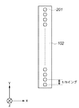
図1は上記マルチヘッドを用いて記録していくインクジェット記録装置主要部の構成を示したものである。同図において、101はインクカートリッジである。これらは、4色のカラーインク、すなわち、ブラック、シアン、マゼンタ、イエローのインクがそれぞれ収容されたインクタンクと、マルチヘッドである記録ヘッド102とにより構成されている。この記録ヘッド102上に配列するインク吐出口の様子をz方向から示したものが図2である。201は記録素子を構成するインク吐出口であり、記録ヘッド102上に1インチ当たりNドットの密度(N dpi)でn個配列されている。再び図1に戻ると、103は紙送りローラであり、104の補助ローラと共に記録媒体Pを抑えながら図中の矢印の方向に回転し、記録媒体Pをy方向に随時搬送する。また105は給紙ローラであり記録媒体Pの給紙を行うとともに、103、104と同様、記録媒体Pを抑える役割も果たす。106は4つのインクカートリッジを支持し、記録とともにこれらを移動させるキャリッジである。これは記録を行っていないとき、或いは記録ヘッド102の回復動作などを行うときには図中の点線で示した位置のホームポジションhに待機するようになっている。
FIG. 1 shows the configuration of the main part of an ink jet recording apparatus for recording using the multihead. In the figure,
記録開始前、ホームポジションhにあるキャリッジ106は、記録開始命令がくると、x方向に移動しながら、記録ヘッド102上のN dpiでn個配列されたインク吐出口201により、記録媒体上に幅n/Nインチだけの記録を行う。記録媒体Pの端部までの記録が終了するとキャリッジ106は元のホームポジションhに戻り、再びx方向への記録のための走査を行う。この最初の記録が終了してから2回目の記録が始まる前に、紙送りローラ103が矢印方向への回転することにより幅n/Nインチだけy方向へ紙送りを行う。この様にしてキャリッジ106の走査毎に、記録ヘッド102によるn/Nインチの幅の記録と紙送りを繰り返し行うことにより、例えば一ページ分の記録を完成することができる。なお、このような同一記録領域に対して1回の記録走査により記録を行う記録モードを1パス記録モードという。
Prior to the start of recording, when a recording start command is received, the
この様な1パス記録モードは、高速に画像を記録する場合には最適である。しかしながら、一般に、紙送り機構による紙送り動作に起因して、ときとしてわずかながら誤差を生じることがある。図3は、紙送り動作に起因する誤差(紙送り誤差)が発生した場合の記録例を示している。図3(a)は紙送りが理想的に行われた場合であり、図3(b)はK走査目での記録ドットとK+1走査目での記録ドットとのつなぎ目が連続せずに幅sの隙間が生じた場合である。このように、紙送り誤差で幅sの隙間が発生する場合には、記録ヘッドの走査方向に幅sの白スジが現れてしまい、記録画像の画質が低下する。このような課題に対する対策の一例として、特許文献1は、図3(c)に示すように、各走査でのつなぎ目の画像領域を一部重複させ、この重複部分の画像領域は各走査で相互補完させて記録する方法を開示している。
Such a one-pass recording mode is optimal when an image is recorded at high speed. However, generally, a slight error may sometimes occur due to the paper feeding operation by the paper feeding mechanism. FIG. 3 shows a recording example when an error (paper feed error) due to the paper feed operation occurs. FIG. 3A shows a case where paper feeding is ideally performed, and FIG. 3B shows a case where the connecting dots between the recording dots at the K-th scanning and the recording dots at the (K + 1) -th scanning are not continuous, and the width s. This is a case where a gap is generated. As described above, when a gap having a width s is generated due to a paper feed error, a white stripe having a width s appears in the scanning direction of the recording head, and the image quality of the recorded image is deteriorated. As an example of countermeasures against such a problem, as shown in FIG. 3C,
また、このようなつなぎ目に発生する白スジ等による記録画像の画質低下は、紙送り誤差が生じた場合だけでなく、記録ヘッドから吐出したインク滴の吐出方向がまっすぐに飛翔しない場合にも発生する。このような場合の記録画像の画質低下に対する対策の一例が特許文献2に開示されている。
In addition, the deterioration in the image quality of the recorded image due to white stripes that occur at the joints occurs not only when a paper feed error occurs but also when the ejection direction of the ink droplets ejected from the recording head does not fly straight. To do. An example of a countermeasure against the degradation of the image quality of a recorded image in such a case is disclosed in
また、画像を高画質で記録するに当たっては、発色性、階調性、一様性など様々な要素が必要となる。特に一様性に関しては、マルチヘッドの製造工程で生じるわずかなノズル毎の製造ばらつきが、記録の際、各ノズルからのインクの吐出量や吐出方向に影響を及ぼし、最終的には記録画像の濃度ムラとして一様性を低下させる原因となる。 In addition, in order to record an image with high image quality, various elements such as color development, gradation, and uniformity are required. In particular, with regard to uniformity, slight manufacturing variations from nozzle to nozzle that occur in the multi-head manufacturing process affect the amount and direction of ink discharged from each nozzle during recording. It becomes a cause of reducing uniformity as density unevenness.
その具体例を図4、図5を用いて説明する。図4(a)において、102は記録ヘッドであり、8個のインク吐出口201が構成されているものとする。43はインク吐出口201から吐出されたインク滴であり、通常はこの図のように揃った吐出量で、揃った方向にインクが吐出されるのが理想である。もし、この様な吐出が行われれば、図4(b)に示したように記録媒体上に大きさ及び配置の揃ったドットが形成される。こうして、図4(c)に示したように全体的にも濃度ムラの無い一様な画像が得られるのである。
A specific example will be described with reference to FIGS. In FIG. 4A,
しかし、実際には、先述したようにノズル1つ1つにはそれぞれバラツキがある。このため、1パス記録モードで記録を行うと、図5(a)に示したようにそれぞれのインク吐出口から吐出されるインク滴の大きさ及び吐出方向にバラツキが生じ、記録媒体上においては、図5(b)に示すようにインク滴が着弾される。図5(b)では、記録ヘッドの走査方向(図中の左右方向)に対し、周期的に白紙の部分が存在したり、また逆に必要以上にドットが重なり合う部分が存在したりしている。或いはこの図中央付近に見られる様な白スジが発生したりしている。この様な状態に記録された部分は、インク吐出口の配列方向に対し、図5(c)に示したような濃度分布となり、濃度ムラとして感知される。一方、紙送り量のバラツキに起因して、各走査でのつなぎ目のスジ(つなぎスジ)が目立つ場合もある。 However, actually, as described above, each nozzle has variations. For this reason, when recording is performed in the one-pass recording mode, as shown in FIG. 5A, the size and direction of ink droplets ejected from the respective ink ejection ports vary, and on the recording medium. Ink droplets are landed as shown in FIG. In FIG. 5B, there are periodically blank paper portions in the scanning direction of the recording head (left and right direction in the drawing), and conversely, there are portions where dots overlap more than necessary. . Or white streaks as seen near the center of the figure are generated. The portion recorded in such a state has a density distribution as shown in FIG. 5C with respect to the arrangement direction of the ink discharge ports, and is detected as density unevenness. On the other hand, due to the variation in the paper feed amount, there may be a noticeable joint line (joint line) in each scan.
そこで、この濃度ムラ及びつなぎスジの対策として、特許文献3にモノクロのインクジェット記録装置において次のような方法が開示されている。図5及び図6によりその方法を簡単に説明する。この方法によると、図5(b)や図6(b)で示した記録領域の記録を完成させるのに、記録ヘッド102を3回走査している(図6(a))。ここでは、その記録領域の半分である4画素単位の領域を2パスでの記録で完成させている。この場合記録ヘッド102の8つのノズルを、図中の上下4つずつの2グループに分け、各ノズルが1回目の走査で記録するドットは、約半分に間引かれたものである。そして2回目の走査時に補完関係となる残りの半分のドットを記録し、4画素単位の領域の記録を完成させる。以上の様な記録モードを、以下マルチパス記録モードと称す。
Therefore, as a countermeasure against the density unevenness and the connecting stripe,
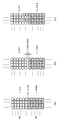
この様なマルチパス記録モードを用いると、図5で示した記録ヘッドを使用しても、各ノズルのバラツキによる記録画像への影響が半減される。このため、記録された画像は図6(b)の様になり、図5(b)のような白スジや黒スジ(ドットが重なることによるスジ)が余り目立たなくなる。したがって、濃度分布も図6(c)に示す様に一定となり、濃度ムラは、1パス記録モードで記録を行った場合と比べてかなり緩和される。この様なマルチパス記録モードで記録を行う際、1走査目と2走査目では、画像データを予め定められた配列に従い互いに埋め合わせる補完関係となるように分割して記録する。通常、この画像データを分割するのに用いられるマスクパターンは、図7に示すように、縦横1画素毎に、千鳥格子状に記録が行われるようなものを用いるのが最も一般的である。したがって、単位記録領域(ここでは4画素単位)においては千鳥格子状に記録をする1走査目と、この1走査目での記録と補完関係となるように記録する2走査目によって記録が完成されるものである。図7の(a)、(b)、(c)は、それぞれこのように記録されるマスクパターンを用いたときに、一定領域の記録がどのように完成されて行くかを、図4〜6と同様、8ノズルを備えたマルチヘッドを用いた場合について説明したものである。 When such a multi-pass printing mode is used, even if the printing head shown in FIG. 5 is used, the influence on the printing image due to the variation of each nozzle is halved. For this reason, the recorded image is as shown in FIG. 6B, and white stripes and black stripes (streaks caused by overlapping dots) as shown in FIG. 5B are not so noticeable. Therefore, the density distribution is also constant as shown in FIG. 6C, and the density unevenness is considerably relaxed compared to the case where printing is performed in the 1-pass printing mode. When recording is performed in such a multi-pass recording mode, the image data is divided and recorded in the first and second scans so as to have a complementary relationship in which the image data are mutually compensated according to a predetermined arrangement. Usually, the mask pattern used to divide the image data is most commonly used, as shown in FIG. 7, in which recording is performed in a staggered pattern for each vertical and horizontal pixel. . Therefore, in the unit recording area (in this case, in units of four pixels), the recording is completed by the first scanning for recording in a staggered pattern and the second scanning for recording so as to complement the recording in the first scanning. It is what is done. FIGS. 7A, 7B, and 7C show how the recording of a certain area is completed when the mask pattern recorded in this way is used. In the same manner as described above, the case where a multi-head having 8 nozzles is used will be described.
まず1走査目では、図中の下側の4ノズルを用いて千鳥格子状の記録を行う(図7(a))。次に2走査目では、紙送りを4画素分(記録ヘッドの長さの1/2)行い、この1走査目での記録と補完関係となるように記録を行う(図7(b))。更に3走査目では、再び4画素分の紙送りを行い、1走査目と同様の記録を行う(図7(c))。この様にして順次4画素分の紙送りと、補完関係となる千鳥格子状の記録を交互に行うことにより、4画素単位の記録領域を1走査毎に完成させていく。以上説明したように、同じ記録領域内に異なる2種類のノズルにより記録が完成されていくことにより、濃度ムラの無い高画質な画像を得ることが可能である。
しかしながら、従来のインクジェット記録方式では以下の問題点があった。高速で高画質な画像を得るためには、小さい液滴を高周期で吐出させる必要があり、この際、図8の記録結果に示されるようなスジが発生していた。このスジは特に記録するドット密度が高い(記録デューティが高い)領域に発生し、記録ヘッドが走査する走査間のつなぎ部で発生することが多い。 However, the conventional ink jet recording method has the following problems. In order to obtain a high-quality image at high speed, it is necessary to eject small droplets at a high cycle. At this time, streaks as shown in the recording result of FIG. 8 have occurred. This streak occurs particularly in an area where the dot density to be recorded is high (recording duty is high), and often occurs at a connecting portion between scans scanned by the recording head.
この現象が発生する原因について図9を用いて説明する。図9は、図8の記録結果を記録した際の記録ヘッド102がインク滴を吐出している様子を示す図である。この図の吐出状態は複数ノズル(例えば256ノズル)存在する記録ヘッドの全ノズルが吐出している状態、すなわち、記録デューティが100%での記録時の状態を示す。この際、ノズル列端部のノズルから吐出されるインクは、ノズル列の内側方向に内射する。これは、全ノズルから高周波数でインクが吐出され、吐出インク滴周囲の空気もインク滴と同じ方向に移動して減圧状態となり、この減圧状態部分の外側の空気が減圧方向に移動する気流が生じ、端部のノズルから吐出されたインク滴が内側に曲がるためである。なお、以降、本現象を本明細書では、端部よれと呼ぶ。この端部よれによって、ノズル列端部のノズルから吐出されたインク滴により形成されるドットの着弾位置にずれが生じ、図8の記録結果のようなスジが発生してしまう。
The cause of this phenomenon will be described with reference to FIG. FIG. 9 is a diagram illustrating a state in which the
この端部よれを回避するために、吐出インク滴の体積を大きくすることが考えられる。これにより、減圧で発生する気流の影響を受けにくくすることができる。しかし、吐出インク滴を大きくしてしまうと、記録画像のインクドットが目立ってしまい、画像品質を落としてしまうことになる。また、吐出周波数の低下、ノズル数又はノズル密度の削減によっても、端部よれを緩和させることができるが、記録スピードが落ちてしまうという弊害が生じる。さらに、記録ヘッドの構成の変更はコスト高を招くことが考えられる。 In order to avoid this edge wobbling, it is conceivable to increase the volume of ejected ink droplets. Thereby, it can be made hard to receive the influence of the airflow generated by pressure reduction. However, if the ejected ink droplets are made larger, the ink dots of the recorded image become conspicuous and the image quality is degraded. Further, although the edge frequency can be reduced by reducing the ejection frequency and the number of nozzles or the nozzle density, there is an adverse effect that the recording speed is lowered. Furthermore, it is conceivable that a change in the configuration of the recording head causes an increase in cost.
一方、この端部よれは、1回の走査で記録するドット密度(記録デューティ)に依存するため、図8に示すような1パス記録モードでの記録の際だけでなく、マルチパス記録モードでの記録の際にも発生する。 On the other hand, since this edge depends on the dot density (recording duty) recorded in one scan, not only when recording in the 1-pass recording mode as shown in FIG. 8, but also in the multi-pass recording mode. It also occurs during recording.
そこで、本発明は、端部よれによる白スジ発生を最小限に抑えたインクジェット記録装置及びその記録方法を提供することを目的とする。 SUMMARY An advantage of some aspects of the invention is that it provides an ink jet recording apparatus that minimizes the occurrence of white streaks due to edge wobbling and a recording method therefor.
上記課題を解決するための本発明は、インクを吐出するためのN個(Nは3以上の整数)のノズルを配列したノズル列を有する記録ヘッドを、前記ノズルが配列された方向と交差する方向に、記録媒体に対して相対的に走査させつつインクを前記記録媒体に吐出して行う走査による記録と、前記走査の方向と交差する方向への前記記録媒体の搬送と、を交互に行うことによって前記記録媒体への記録を完成させるインクジェット記録方法であって、前記ノズル列のうち前記搬送の方向における上流側の端部に連続して配置されたX個(Xは1以上の整数)のノズルを用いて前記記録媒体の単位領域に1回目の前記走査による記録を行う第1の工程と、当該記録媒体を、K(Kは1以上の整数)回、(N−X)/K個のノズルに相当する距離だけ搬送を行う間に、前記ノズル列のうち、前記上流側の端部のX個のノズルと、前記搬送の方向における下流側の端部に連続して配置されたX個のノズルとを除くそれぞれX個のノズルを用いて、前記単位領域にK−1回の前記走査による記録を行う第2の工程と、さらに前記記録媒体の前記搬送を行った後、前記下流側の端部のX個のノズルを用いて、当該単位領域にK+1回目の前記走査による記録を行う第3の工程と、を有し、前記KがKIn order to solve the above problems, the present invention crosses a recording head having a nozzle array in which N (N is an integer of 3 or more) nozzles for ejecting ink intersect with the direction in which the nozzles are arranged. Recording by scanning by ejecting ink onto the recording medium while scanning relative to the recording medium in the direction, and conveying the recording medium in a direction intersecting the scanning direction are alternately performed. In the ink jet recording method for completing recording on the recording medium, the X nozzles are continuously arranged at the upstream end in the transport direction in the nozzle row (X is an integer of 1 or more). A first step of performing recording by the first scanning on the unit area of the recording medium using the nozzles of the recording medium, and the recording medium is (N−X) / K K (K is an integer of 1 or more) times. The distance is equivalent to one nozzle While carrying, each of the nozzle rows excluding the X nozzles at the upstream end and the X nozzles arranged continuously at the downstream end in the carrying direction A second step of performing printing by the scan of the unit area K-1 times using the X nozzles, and further carrying the recording medium, and then transporting the recording medium to the downstream end X And a third step of performing printing by the (K + 1) th scanning in the unit area using the nozzles, and K is K 11 の場合の前記XをXX in the case of X 11 としたときに、前記Kが前記KThe K is the K 11 より小さいKSmaller K 22 の場合の前記Xは前記XX in the case of 11 より大きいXGreater than X 22 となることを特徴とするインクジェット記録方法である。This is an ink jet recording method.
上記課題を解決するための別の本発明は、インクを吐出するためのN個(Nは3以上の整数)のノズルを配列したノズル列を有する記録ヘッドを備え、前記ノズルが配列された方向と交差する方向に、前記記録ヘッドを記録媒体に対して相対的に走査させつつインクを前記記録媒体に吐出して行う走査による記録と、前記走査の方向と交差する方向への前記記録媒体の搬送と、を交互に行うことによって前記記録媒体への記録を完成させるインクジェット記録装置であって、前記ノズル列のうち前記搬送の方向における上流側の端部に連続して配置されたX個(Xは1以上の整数)のノズルを用いて前記記録媒体の単位領域に1回目の前記走査による記録を行う第1の手段と、当該記録媒体を、K(Kは1以上の整数)回、(N−X)/K個のノズルに相当する距離だけ搬送を行う間に、前記ノズル列のうち、前記上流側の端部のX個のノズルと、前記搬送の方向における下流側の端部に連続して配置されたX個のノズルとを除くそれぞれX個のノズルを用いて、前記単位領域にK−1回の前記走査による記録を行う第2の手段と、さらに前記記録媒体の前記搬送を行った後、前記下流側の端部のX個のノズルを用いて、当該単位領域にK+1回目の前記走査による記録を行う第3の手段と、を有し、前記KがKAnother aspect of the present invention for solving the above-described problem includes a recording head having a nozzle row in which N (N is an integer of 3 or more) nozzles for ejecting ink, and the direction in which the nozzles are arranged. In the direction intersecting with the recording head by scanning the recording head relative to the recording medium while ejecting ink onto the recording medium, and recording of the recording medium in the direction intersecting with the scanning direction. An ink jet recording apparatus that completes recording on the recording medium by alternately carrying and transporting, wherein X nozzles are arranged consecutively at an upstream end in the carrying direction of the nozzle row ( X is an integer of 1 or more) first means for performing printing by the first scanning in the unit area of the recording medium, and the recording medium is K (K is an integer of 1 or more) times, (N-X) / K While carrying the distance corresponding to the nozzles, X nozzles arranged successively from the X nozzles at the upstream end and the downstream end in the carrying direction of the nozzle row A second means for performing printing by the scan of K-1 times in the unit area using X nozzles excluding the nozzles of the nozzles, and further carrying the recording medium and then downstream of the recording medium. And a third means for performing printing by the K + 1th scanning in the unit area using the X nozzles at the end of the K, where K is K
11
の場合の前記XをXX in the case of X
11
としたときに、前記Kが前記KThe K is the K
11
より小さいKSmaller K
22
の場合の前記Xは前記XX in the case of
11
より大きいXGreater than X
22
となることを特徴とするインクジェット記録装置である。An ink jet recording apparatus characterized in that.
本発明によれば、端部よれによる白スジ発生を最小限に抑えたインクジェット記録装置及びその記録方法を提供することができる。さらに、このインクジェット記録装置及びその記録方法により、高画質の画像記録を高速にて行うことが可能になる。 According to the present invention, it is possible to provide an ink jet recording apparatus and a recording method thereof in which the occurrence of white streaks due to the edge portion is minimized. Furthermore, this inkjet recording apparatus and recording method thereof can perform high-quality image recording at high speed.
次に、本発明の実施例について図面を参照して説明する。 Next, embodiments of the present invention will be described with reference to the drawings.
なお、この明細書において、「記録」(以下、「プリント」とも称する)とは、文字、図形等有意の情報を形成する場合のみならず、有意無意を問わず、広く記録媒体上に画像、模様、パターン等を形成する、又は媒体の加工を行う場合も表すものとする。また、人間が視覚で知覚し得るように顕在化したものであるか否かを問わない。 In this specification, “recording” (hereinafter also referred to as “printing”) is not only for forming significant information such as characters and figures, but also for images on a wide range of recording media, regardless of significance. A case where a pattern, a pattern, or the like is formed or a medium is processed is also expressed. It does not matter whether it has been made obvious so that humans can perceive it visually.
また、「記録媒体」とは、一般的な記録装置で用いられる紙のみならず、広く、布、プラスチック・フィルム、金属板、ガラス、セラミックス、木材、皮革等、インクを受容可能なものも表すものとする。 “Recording medium” refers not only to paper used in general recording apparatuses but also widely to cloth, plastic film, metal plate, glass, ceramics, wood, leather, and the like that can accept ink. Shall.
さらに、「インク」とは、上記「記録」の定義と同様広く解釈されるべきもので、記録媒体上に付与されることによって、画像、模様、パターン等の形成又は記録媒体の加工、或いはインクの処理に供され得る液体を表すものとする。インクの処理としては、例えば記録媒体に付与されるインク中の色剤の凝固又は不溶化させることが挙げられる。 Further, the term “ink” should be interpreted broadly in the same way as the definition of “recording” described above. When applied to a recording medium, it forms an image, a pattern, a pattern or the like, or processes the recording medium. It represents a liquid that can be subjected to the treatment. Examples of the ink treatment include solidification or insolubilization of the colorant in the ink applied to the recording medium.
なお、下記の実施例においては、図2で示した複数の記録素子からなる記録素子列を有する記録ヘッドを用いた。また、図1で示したこの記録素子列の配列方向と交差する方向に記録ヘッドを走査するキャリッジを有するインクジェット記録装置を用いた。 In the following examples, a recording head having a recording element array composed of a plurality of recording elements shown in FIG. 2 was used. Further, an ink jet recording apparatus having a carriage that scans the recording head in a direction crossing the arrangement direction of the recording element arrays shown in FIG. 1 was used.
まず、本発明を好適に実施するインクジェット記録装置の制御構成について説明する。 First, the control configuration of an ink jet recording apparatus that suitably implements the present invention will be described.
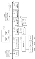
図10は、インクジェット記録装置の制御構成を示すブロック図である。 FIG. 10 is a block diagram illustrating a control configuration of the inkjet recording apparatus.
図10において、メインバスライン1005に対して夫々アクセスする画像入力部1003、それに対応する画像信号処理部1004、中央制御部としてのCPU1000といったソフト関係の処理手段を備える。また、操作部1006、回復部制御回路1007、インクジェットヘッド温度制御回路1014、ヘッド駆動制御回路1015、主走査方向へのキャリッジ駆動制御回路1016、副走査方向への紙送り制御回路1017といったハード関係の処理手段を備える。
In FIG. 10, there are provided software-related processing means such as an image input unit 1003 accessing the
CPU1000は、通常ROM1001とランダムアクセスメモリ(RAM)1002を有し、入力情報に対して適正な記録条件を与えて記録ヘッド102を駆動して記録を行う。また、ROM1001内には、予めヘッド回復タイミングチャートを実行するプログラムが格納されており、CPU1000は、必要に応じて予備吐出条件等の回復条件を回復部制御回路1007、記録ヘッド102、保温ヒータ等に与える。さらに、CPU1000は、前記記録制御及び回復制御の他、記録媒体の搬送制御も行い、記録モードに応じた記録媒体の搬送量の制御を行う。
The
回復部モータ1008は、前述したような記録ヘッド102とこれに対向離間するクリーニングブレード1009やキャップ1010、吸引ポンプ1011を駆動する。ヘッド駆動制御回路1015は、記録ヘッド102のインク吐出用電気熱変換体の駆動条件を実行するもので、通常予備吐出や記録用インク吐出を記録ヘッド102に行わせる。
The
一方、記録ヘッド102のインク吐出用の電気熱変換体が設けられている素子基板には、保温ヒータが設けられており、記録ヘッド内のインク温度を所望設定温度に加熱調整することができる。また、サーミスタ1012は、同様に上記素子基板に設けられているもので、実質的な記録ヘッド内部のインク温度を測定するためのものである。サーミスタ1012は、素子基板ではなく外部に設けられていても良く記録ヘッド102の周囲近傍にあっても良い。
On the other hand, the element substrate on which the electrothermal transducer for ink ejection of the
次に、本発明の実施例について図面を参照して説明する。なお、以下の各実施例では、図3(c)に示すように、各走査でのつなぎ目の画像領域に記録を行う際、記録媒体上において、先の走査での記録による記録ドットの位置と後の走査での記録による記録ドットの位置とを異ならせるように記録させている。 Next, embodiments of the present invention will be described with reference to the drawings. In each of the following embodiments, as shown in FIG. 3C, when recording is performed on the joint image area in each scan, the position of the recording dot by the recording in the previous scan is recorded on the recording medium. The recording is performed so that the position of the recording dot by the recording in the later scanning is different.
(実施例1)
本実施例で使用した記録ヘッド102は、1インチ当たり600ドット(600dpi)の密度で256個の吐出口を備えており、1走査あたりの記録素子列による記録幅は256/600インチ≒10.84mmである。また本実施例では、図2に示した個々のインク吐出口201から吐出されるインク滴の大きさは5plである。また、この量のインク滴を安定して吐出するための吐出周波数は30KHz、吐出速度は約18m/秒である。更に、このような記録ヘッド102を搭載したキャリッジ106の走査速度は、25インチ/秒であり、これにより走査方向には1200dpiの記録密度で画像が形成される。
Example 1
The
図11は、本実施例の記録ヘッド102を256個の全てのインク吐出口を使用して1回の走査で記録するときのドット密度(記録デューティ)と、気流による端部よれが発生するノズル列端部からのノズル数との関係を示したグラフである。なお、以下、気流による端部よれが発生するノズル列端部からのノズル数を、単に、端部よれが発生するノズル数と呼ぶ。記録デューティが100%とは、256個の全てのインク吐出口からキャリッジの走査速度が25インチ/秒、吐出周波数30KHzで、走査方向に1200dpiの記録密度で記録した状態である。この時、端部よれが発生するノズル数は31ノズルであり、この31ノズルで記録した領域に関しては着弾位置のズレが発生している。
FIG. 11 shows a dot density (recording duty) when the
この図11より、記録デューティが低くなると、端部よれが発生するノズル数が減少することがわかる。また、記録デューティが高くなるにつれて、端部よれが発生するノズル数の増加率は減少していることがわかる。 From FIG. 11, it can be seen that the number of nozzles that cause edge deflection decreases as the recording duty decreases. It can also be seen that as the recording duty increases, the increase rate of the number of nozzles that cause edge deflection decreases.
図12は、本実施例で用いるマスクパターンを示している。図12の(a)−1と(a)−2は、記録デューティが100%の画像データに対して、各々1/2の記録デューティとなるマスク率のマスクパターンであり、相互に補完関係にあるマスクパターンを示す。また、図12の(b)−1と(b)−2と(b)−3は、記録デューティが100%の画像データに対して、各々1/3の記録デューティとなるマスク率のマスクパターンであり、相互に補完関係にあるマスクパターンを示す。 FIG. 12 shows a mask pattern used in this embodiment. (A) -1 and (a) -2 in FIG. 12 are mask patterns having mask ratios each having a recording duty of 1/2 with respect to image data with a recording duty of 100%, and are complementary to each other. A mask pattern is shown. Further, (b) -1, (b) -2, and (b) -3 in FIG. 12 are mask patterns having mask ratios each having a recording duty of 1/3 for image data with a recording duty of 100%. The mask patterns are complementary to each other.
図13は、本実施例の1パス記録モードの記録動作を説明する図である。なお、本実施例の1パス記録モードは、記録ヘッドの1回の走査により記録領域の全域の画像を完成させる記録モードではない。本実施例では、記録ヘッド中央のノズルが通過する領域(以下、通常領域)については、記録ヘッドの1回の走査により画像を記録する。一方、端部よれが発生する記録ヘッド端部のノズルが通過する領域(以下、端部領域)については、記録ヘッドの両端部のノズルが同一領域を記録するように、記録ヘッドの2回の走査によって画像を記録する。以下に、本実施例の1パス記録モードにおける記録動作を具体的に説明する。 FIG. 13 is a diagram for explaining the recording operation in the one-pass recording mode of this embodiment. Note that the one-pass recording mode of this embodiment is not a recording mode in which an image of the entire recording area is completed by a single scan of the recording head. In this embodiment, an image is recorded by a single scan of the recording head in an area through which the nozzle at the center of the recording head passes (hereinafter referred to as a normal area). On the other hand, with respect to a region through which the nozzles at the end of the print head that pass through the end (hereinafter referred to as end region) pass, the nozzles at both ends of the print head record the same region twice. An image is recorded by scanning. Hereinafter, the recording operation in the one-pass recording mode of the present embodiment will be specifically described.
まず、図13に示す1走査目で256ノズルの内の上流側(給紙側)のノズル番号である1番目のn1から32番目のn32までの32ノズルを用いて記録できるように、記録媒体Pを記録ヘッドの走査方向とは異なるY方向に搬送する。 First, in the first scan shown in FIG. 13, the recording medium is capable of recording using 32 nozzles from the first n1 to the 32nd n32 which are nozzle numbers on the upstream side (feed side) of 256 nozzles. P is conveyed in the Y direction different from the scanning direction of the recording head.
搬送終了後、1走査目において、記録媒体Pの画像領域[1]−1を上流側(給紙側)のn1からn32までの32ノズルを使用し、図12の(a)−1のマスクパターンを用いて記録する。 After the conveyance is finished, in the first scan, 32 nozzles from n1 to n32 on the upstream side (feed side) are used for the image area [1] -1 of the recording medium P, and the mask shown in FIG. Record using a pattern.
続いて、256ノズルの全ノズルを使用して記録できるよう記録媒体PをY方向に224[dot/600dpi]分の搬送を行う。別の表現をすると、記録ヘッドの記録素子列による記録幅256[dot/600dpi]よりも短い幅224[dot/600dpi]だけ記録媒体の搬送を行う。 Subsequently, the recording medium P is conveyed in the Y direction for 224 [dot / 600 dpi] so that recording can be performed using all 256 nozzles. In other words, the recording medium is conveyed by a width 224 [dot / 600 dpi] shorter than the recording width 256 [dot / 600 dpi] by the recording element array of the recording head.
搬送終了後、2走査目で、1走査目で図12の(a)−1のマスクパターンを用いて記録した画像領域[1]−1を、下流側(排紙側)のn225からn256までの32ノズルを使用し、図12の(a)−2のマスクパターンを用いて記録し画像を完成させる。 After the conveyance is completed, the image area [1] -1 recorded using the mask pattern of (a) -1 in FIG. 12 at the second scan from the second scan to the n256 from the downstream (sheet discharge side) n225. 32 nozzles are used, and recording is performed using the mask pattern shown in FIG.
画像領域[2]−1に関しては、1走査目の画像領域[1]−1を記録した時と同様に、上流側のn1からn32までの32ノズルを使用し、図12の(a)−1のマスクパターンを用いて記録する。 For the image area [2] -1, 32 nozzles from n1 to n32 on the upstream side are used in the same manner as when the image area [1] -1 for the first scan is recorded, and FIG. Recording is performed using one mask pattern.
画像領域[2]−2に関しては、中央部のn33からn224までの192ノズルを使用し、間引き(マスク)無しで記録し、画像を完成させる。 For the image area [2] -2, 192 nozzles from n33 to n224 in the center are used and recording is performed without thinning out (masking) to complete the image.
続いて、記録媒体PをY方向に224[dot/600dpi]分の搬送を行う。搬送終了後、3走査目において、2走査目で図12の(a)−1のマスクパターンを用いて記録した画像領域[2]−1を、下流側のn225からn256までの32ノズルを使用し、図12の(a)−2のマスクパターンを用いて記録し、画像を完成させる。 Subsequently, the recording medium P is conveyed in the Y direction for 224 [dot / 600 dpi]. After the conveyance is completed, in the third scan, 32 nozzles from n225 to n256 on the downstream side are used for the image region [2] -1 recorded using the mask pattern of FIG. 12A-1 in the second scan. Then, recording is performed using the mask pattern of (a) -2 in FIG. 12 to complete the image.
画像領域[3]−1に関しては、1走査目の画像領域[1]−1、2走査目の画像領域[2]−1を記録した時と同様に、上流側のn1からn32までの32ノズルを使用し、図12の(a)−1のマスクパターンを用いて記録する。 As for the image area [3] -1, as in the case of recording the image area [1] for the first scan and the image area [2] -1 for the first scan, 32 from n1 to n32 on the upstream side. Using a nozzle, recording is performed using the mask pattern shown in FIG.
画像領域[3]−2に関しては、2走査目の画像領域[2]−2を記録した時と同様に、中央部のn33からn224までの192ノズルを使用し、間引き無しで記録し、画像を完成させる。 For the image area [3] -2, as in the case of recording the image area [2] -2 for the second scan, recording is performed without thinning using 192 nozzles from n33 to n224 in the center. To complete.
4走査目以降は、記録媒体PをY方向に224[dot/600dpi]分の搬送と3走査目の記録動作を繰り返しながら画像を完成させる。 After the fourth scan, the image is completed while the recording medium P is conveyed in the Y direction for 224 [dot / 600 dpi] and the recording operation for the third scan is repeated.
1パス記録モードでは、最大の記録デューティは100%である。このことから、図11より、端部よれが発生するノズル数は、最大で31ノズルとなることがわかる。そこで、本実施例では、記録ヘッド端部の32ノズルが通過する領域を端部領域とし、この端部領域については記録ヘッドの両端部を用いて、記録ヘッドの2回の走査により画像を完成させる。 In the 1-pass printing mode, the maximum printing duty is 100%. From this, it can be seen from FIG. 11 that the maximum number of nozzles that cause edge deflection is 31 nozzles. Therefore, in this embodiment, an area through which the 32 nozzles at the end of the recording head pass is defined as an end area, and an image is completed by scanning the recording head twice with respect to the end area. Let
つまり、本実施例の1パス記録モードでは、256個のノズルの内上流側のn1からn32の32ノズルを使用して記録する画像領域を、下流側のn225からn256の32ノズルを使用して記録する画像領域と重なるように記録させている。このため、記録ヘッドが走査する走査間のつなぎ部で発生していた白スジによる画像劣化を軽減することができた。 That is, in the one-pass printing mode of the present embodiment, an image area to be printed using 32 nozzles n1 to n32 on the upstream side of 256 nozzles, and 32 nozzles on the downstream side n225 to n256 are used. Recording is performed so as to overlap the image area to be recorded. For this reason, it was possible to reduce image deterioration due to white stripes that occurred at the connecting portion between the scans scanned by the recording head.
図14は、本実施例のマルチパス記録モード(2パス記録モード)の記録動作を説明する図である。なお、本実施例の2パス記録モードは、記録ヘッドの2回の走査により記録領域の全域の画像を完成させる記録モードではない。本実施例では、通常領域については記録ヘッドの2回の走査により画像を記録するが、端部領域については記録ヘッドの3回の走査によって画像を記録する。以下に、本実施例の2パス記録モードにおける記録動作を具体的に説明する。 FIG. 14 is a diagram for explaining the recording operation in the multi-pass recording mode (two-pass recording mode) of this embodiment. Note that the two-pass recording mode of this embodiment is not a recording mode in which an image of the entire recording area is completed by two scans of the recording head. In this embodiment, an image is recorded by scanning the recording head twice for the normal area, but an image is recorded by scanning the recording head three times for the end area. Hereinafter, the recording operation in the two-pass recording mode of this embodiment will be specifically described.
まず、図14に示す1走査目で256ノズルの内の上流側のノズル番号である1番目のn1から26番目のn26までの26ノズルを用いて記録できるように、記録媒体PをY方向に搬送する。 First, in the first scan shown in FIG. 14, the recording medium P is moved in the Y direction so that recording can be performed using 26 nozzles from the first n1 to the 26th n26, which are the upstream nozzle numbers of 256 nozzles. Transport.
搬送終了後、1走査目において、記録媒体Pの画像領域[1]−1を、上流側のn1からn26までの26ノズルを使用し、図12の(b)−1のマスクパターンを用いて記録する。 After the conveyance is completed, in the first scan, the image area [1] -1 of the recording medium P is used for the upstream 26 nozzles from n1 to n26, and using the mask pattern shown in FIG. Record.
続いて、256ノズルの内の上流側からn1からn141までの141ノズルを用いて記録できるように記録媒体PをY方向に115[dot/600dpi]分の搬送を行う。 Subsequently, the recording medium P is conveyed by 115 [dot / 600 dpi] in the Y direction so that recording can be performed using 141 nozzles n1 to n141 from the upstream side of the 256 nozzles.
搬送終了後、2走査目において、1走査目で図12の(b)−1のマスクパターンを用いて記録した画像領域[1]−1を、中央部のn116からn141までの26ノズルを使用し、図12の(b)−2のマスクパターンを用いて記録する。 After the conveyance is completed, in the second scan, the image area [1] -1 recorded using the mask pattern shown in FIG. 12B-1 in the first scan uses 26 nozzles from n116 to n141 in the center. Then, recording is performed using the mask pattern shown in FIG.
画像領域[2]−1に関しては、1走査目の画像領域[1]−1を記録した時と同様に、上流側のn1からn26までの26ノズルを使用し、図12の(b)−1のマスクパターンを用いて記録する。 For the image area [2] -1, as in the case of recording the image area [1] -1 for the first scan, 26 nozzles from n1 to n26 on the upstream side are used, and (b)-of FIG. Recording is performed using one mask pattern.
画像領域[2]−2に関しては、中央部のn27からn115までの89ノズルを使用し、図12の(a)−1のマスクパターンを用いて記録する。 For the image region [2] -2, 89 nozzles from n27 to n115 in the center are used and recording is performed using the mask pattern of (a) -1 in FIG.
続いて、256ノズルの全ノズルを使用して記録できるように記録媒体PをY方向に115[dot/600dpi]分の搬送を行う。 Subsequently, the recording medium P is conveyed by 115 [dot / 600 dpi] in the Y direction so that recording can be performed using all 256 nozzles.
搬送終了後、3走査目において、1走査目で図12の(b)−1のマスクパターンを用いて記録し、2走査目で図12の(b)−2のマスクパターンを用いて記録した画像領域[1]−1に対して記録する。具体的には、下流側のn231からn256までの26ノズルを用いて図12の(b)−3のマスクパターンを用いて記録し、画像を完成させる。 After the conveyance is completed, in the third scan, recording is performed using the mask pattern of FIG. 12B-1 in the first scan, and recording is performed using the mask pattern of FIG. 12B-2 in the second scan. Recording is performed on the image area [1] -1. Specifically, recording is performed using the mask pattern of (b) -3 of FIG. 12 using 26 nozzles from n231 to n256 on the downstream side to complete the image.
また、2走査目で図12の(a)−1のマスクパターンを用いて記録した画像領域[2]−2に関しては、中央部のn142からn230までの89ノズルを用いて図12の(a)−2のマスクパターンを用いて記録し、画像を完成させる。 Further, for the image area [2] -2 recorded using the mask pattern of FIG. 12A-1 in the second scan, 89 nozzles from n142 to n230 in the center are used as shown in FIG. ) -2 using the mask pattern of -2 to complete the image.
画像領域[2]−1に関しては、2走査目で画像領域[1]−1を記録した時と同様に記録する。具体的には、2走査目で図12の(b)−1のマスクパターンを用いて記録した画像領域[2]−1を中央部のn116からn141までの26ノズルを使用し、図12の(b)−2のマスクパターンを用いて記録する。 The image area [2] -1 is recorded in the same manner as when the image area [1] -1 was recorded in the second scan. Specifically, in the second scan, the image area [2] -1 recorded using the mask pattern of (b) -1 in FIG. (B) Recording is performed using the mask pattern of -2.
画像領域[3]−1に関しては、1走査目で画像領域[1]−1を記録した時や2走査目で画像領域[2]−1を記録した時と同様に、上流側のn1からn26までの26ノズルを使用し、図12の(b)−1のマスクパターンを用いて記録する。 With respect to the image area [3] -1, from the upstream n1, the image area [1] -1 is recorded in the first scan and the image area [2] -1 is recorded in the second scan. Recording is performed using the 26 nozzles up to n26 and using the mask pattern shown in FIG.
画像領域[3]−2に関しては、2走査目で画像領域[2]−2を記録した時と同様に、中央部のn27からn115までの89ノズルを使用し、図12の(a)−1のマスクパターンを用いて記録する。 For the image area [3] -2, as in the case of recording the image area [2] -2 in the second scan, 89 nozzles from n27 to n115 in the center are used, and (a)-in FIG. Recording is performed using one mask pattern.
続いて、記録媒体PをY方向に115[dot/600dpi]分の搬送を行う。 Subsequently, the recording medium P is conveyed in the Y direction for 115 [dot / 600 dpi].
搬送終了後、4走査目において、2走査目で図12の(b)−1のマスクパターンを用いて記録し、3走査目で図12の(b)−2のマスクパターンを用いて記録した画像領域[2]−1に対して記録する。具体的には、下流側のn231からn256までの26ノズルを用いて図12の(b)−3のマスクパターンを用いて記録し、画像を完成させる。 After the conveyance is completed, in the fourth scan, recording is performed using the mask pattern of FIG. 12B-1 in the second scan, and recording is performed using the mask pattern of FIG. 12B-2 in the third scan. Recording is performed on the image area [2] -1. Specifically, recording is performed using the mask pattern of (b) -3 of FIG. 12 using 26 nozzles from n231 to n256 on the downstream side to complete the image.
また、3走査目で図12の(a)−1のマスクパターンを用いて記録した画像領域[3]−2に関しては、中央部のn142からn230までの89ノズルを用いて図12の(a)−2のマスクパターンを用いて記録し、画像を完成させる。 For the image region [3] -2 recorded using the mask pattern of FIG. 12A-1 in the third scan, 89 nozzles from n142 to n230 in the center are used as shown in FIG. ) -2 using the mask pattern of -2 to complete the image.
画像領域[3]−1に関しては、2走査目で画像領域[1]−1を記録した時や3走査目で画像領域[2]−1を記録した時と同様に記録する。具体的には、1走査前の3走査目において図12の(b)−1のマスクパターンを用いて記録した画像領域[3]−1を中央部のn116からn141までの26ノズルを使用し、図12の(b)−2のマスクパターンで記録する。 The image area [3] -1 is recorded in the same manner as when the image area [1] -1 is recorded in the second scan or the image area [2] -1 is recorded in the third scan. Specifically, 26 nozzles from n116 to n141 in the central portion are used in the image area [3] -1 recorded using the mask pattern of (b) -1 in FIG. 12 in the third scan before one scan. Recording is performed with the mask pattern (b) -2 in FIG.
画像領域[4]−1に関しては、1走査目で画像領域[1]−1を記録した時、2走査目で画像領域[2]−1を記録した時、3走査目で画像領域[3]−1を記録した時と同様に記録する。具体的には、上流側のn1からn26までの26ノズルを使用し、図12の(b)−1のマスクパターンを用いて記録する。 Regarding the image area [4] -1, when the image area [1] -1 is recorded at the first scan, when the image area [2] -1 is recorded at the second scan, the image area [3] at the third scan. ] -1 is recorded in the same manner as when -1. Specifically, 26 nozzles from n1 to n26 on the upstream side are used, and recording is performed using the mask pattern of (b) -1 in FIG.
画像領域[4]−2に関しては、2走査目で画像領域[2]−2を記録した時や3走査目で画像領域[3]−2を記録した時と同様に、中央部のn27からn115までの89ノズルを使用し、図12の(a)−1のマスクパターンを用いて記録する。5走査目以降は、記録媒体PをY方向に115[dot/600dpi]分の搬送を行うのと4走査目の記録動作を繰り返しながら画像を完成させる。 As for the image area [4] -2, from the n27 in the center, as in the case where the image area [2] -2 is recorded in the second scan and the image area [3] -2 is recorded in the third scan. Recording is performed using 89 nozzles up to n115 and using the mask pattern shown in FIG. After the fifth scan, the image is completed while the recording medium P is conveyed in the Y direction for 115 [dot / 600 dpi] and the recording operation for the fourth scan is repeated.
2パス記録モードでは、最大の記録デューティは50%である。このことから、図11より、気流による端部よれが発生するノズル列端部からのノズル数は、最大で25ノズルとなることがわかる。そこで、本実施例では、記録ヘッド両端の26ノズルが通過する領域を端部領域とし、この端部領域については記録ヘッドの両端部による記録走査を含む、記録ヘッドの3回の走査により画像を完成させる。 In the 2-pass printing mode, the maximum printing duty is 50%. From this, it can be seen from FIG. 11 that the maximum number of nozzles from the end of the nozzle row where the end sway by the airflow occurs is 25 nozzles. Therefore, in this embodiment, an area through which the 26 nozzles at both ends of the recording head pass is defined as an end area, and an image is obtained by scanning the recording head three times including the recording scanning by both ends of the recording head. Finalize.
つまり、本実施例の2パス記録モードでは、256個のノズルの内上流側のn1からn26の26ノズルを使用して記録する画像領域を、下流側のn231からn256の26ノズルを使用して記録する画像領域と重なるように記録させている。このため、記録ヘッドが走査する走査間のつなぎ部で発生していた白スジによる画像劣化を軽減することができた。 In other words, in the two-pass recording mode of this embodiment, an image area to be recorded using 26 nozzles n1 to n26 on the upstream side of 256 nozzles is used, and 26 nozzles n231 to n256 on the downstream side are used. Recording is performed so as to overlap the image area to be recorded. For this reason, it was possible to reduce image deterioration due to white stripes that occurred at the connecting portion between the scans scanned by the recording head.
以上の様に、記録ヘッドの各走査間のつなぎ目で発生していた白スジによる画像劣化を軽減するのに、図13で説明した1パス記録モードでは、記録ヘッドの両端部を用いて記録される領域、すなわち端部領域の幅ΔY1が32ノズル分であった。 As described above, in order to reduce the image deterioration due to the white streak occurring at the joint between the scans of the recording head, in the one-pass recording mode described with reference to FIG. 13, recording is performed using both ends of the recording head. That is, the width ΔY1 of the end region is 32 nozzles.
これに対し、図14で説明したマルチパス記録モード(2パス記録モード)では、端部領域の搬送方向の幅ΔY2がΔY1の32ノズル分よりも少ない26ノズル分であった。このように記録することにより、記録ヘッドの各走査間のつなぎ目で発生していた白スジによる画像劣化を軽減できるだけでなく、高速に記録することが可能となった。 On the other hand, in the multi-pass printing mode (two-pass printing mode) described with reference to FIG. 14, the width ΔY2 in the transport direction of the end region is 26 nozzles, which is smaller than 32 nozzles of ΔY1. By recording in this way, it is possible not only to reduce image deterioration due to white streaks occurring at the joint between the scans of the recording head, but also to enable high-speed recording.
さらに、本実施例では、端部領域の記録走査回数(図13の記録動作では2回、図14の記録動作では3回)を、通常領域の記録走査回数(図13の記録動作では1回、図14の記録動作では2回)よりも多くした。こうして、端部領域の1走査当りの記録密度を、通常領域の1走査当りの記録密度よりも低くした。このように記録することにより、気流による端部よれが発生するノズル列端部からのノズル数も更に減少させることが可能となり、高画質化と更なる高速化の両立が可能となった。 Further, in this embodiment, the number of recording scans in the end region (2 times in the recording operation of FIG. 13 and 3 times in the recording operation of FIG. 14) is set to the number of recording scans of the normal region (1 time in the recording operation of FIG. 13). 14 in the recording operation of FIG. In this way, the recording density per scan in the end area was made lower than the recording density per scan in the normal area. By recording in this way, it is possible to further reduce the number of nozzles from the end portion of the nozzle row where the end portion due to the airflow occurs, and it is possible to achieve both higher image quality and higher speed.
図18は、本実施例の記録方法を示すフローチャートである。 FIG. 18 is a flowchart showing the recording method of this embodiment.
記録動作を開始すると、まず、ステップS110で、記録モードをユーザが操作部1006又は外部ホスト装置から選択する。1パス記録モードを選択した場合は、ステップS120で、1回の記録走査を行う。次に、ステップS130により、ノズル列の上流側端部と下流側端部とが同一の領域(端部領域)を記録するように、第1の搬送量だけ記録媒体の搬送を行う。次に、ステップS140で、1回の記録走査を行う。ここで全画像領域の記録が終了したのであれば記録動作を終了し、全画像領域の記録が終了していないのであればステップS130に戻り記録動作を続行する(ステップS150)。 ステップS110で、ユーザが1パス記録モードを選択しなかった場合は、ステップS160で、1回の記録走査を行う。次に、ステップS170により、ノズル列の上流側端部と下流側端部とが同一の領域(端部領域)を記録するように、第2の搬送量だけ記録媒体の搬送を行う。ここで、第2の搬送量は、第1の搬送量よりも小さいことを特徴とする。次に、ステップS180で、1回の記録走査を行う。ここで全画像領域の記録が終了したのであれば記録動作を終了し、全画像領域の記録が終了していないのであればステップS170に戻り記録動作を続行する(ステップS190)。
When the recording operation is started, first, in step S110, the user selects a recording mode from the
(実施例2)
実施例1では、1パス記録モードとマルチパス記録モードとを実施できる構成において説明を行った。本実施例では、複数のマルチパス記録モードを実行可能な形態を例に説明を行う。本実施例では、実施例1の2パス記録モード(図14参照)と、以下に説明する4パス記録モードとを実行できる構成である。
(Example 2)
In the first embodiment, the description has been given of the configuration in which the 1-pass printing mode and the multi-pass printing mode can be performed. In this embodiment, a description will be given by taking as an example a form capable of executing a plurality of multi-pass printing modes. In this embodiment, the two-pass printing mode (see FIG. 14) of the first embodiment and the four-pass printing mode described below can be executed.
本実施例で使用した記録ヘッドは、実施例1で使用した記録ヘッド102と同じ記録ヘッドとする。
The recording head used in this example is the same as the
また、図15は、本実施例で用いるマスクパターンを示している。図15の(a)−1と(a)−2と(a)−3と(a)−4は、記録デューティが100%の画像データに対して、各々1/4の記録デューティとなるマスク率のマスクパターンであり、相互に補完関係にあるマスクパターンを示す。また、図15の(b)−1と(b)−2と(b)−3と(b)−4と(b)−5は、記録デューティが100%の画像データに対して、各々1/5の記録デューティとなるマスク率のマスクパターンであり、相互に補完関係にあるマスクパターンを示す。 FIG. 15 shows a mask pattern used in this embodiment. In FIG. 15, (a) -1, (a) -2, (a) -3, and (a) -4 are masks each having a recording duty of 1/4 for image data with a recording duty of 100%. This is a mask pattern of a ratio, and shows a mask pattern that is complementary to each other. Also, (b) -1, (b) -2, (b) -3, (b) -4, and (b) -5 in FIG. 15 are each 1 for image data with a recording duty of 100%. This is a mask pattern having a mask ratio with a recording duty of / 5, and shows a mask pattern that is complementary to each other.
図16は、本実施例の4パス記録モードの記録動作を説明する図である。本実施例の4パス記録モードも、記録ヘッドの4回の走査により記録領域の全域の画像を完成させる記録モードではない。本実施例の4パス記録モードでは、通常領域については記録ヘッドの4回の走査により画像を記録するが、端部領域については記録ヘッドの5回の走査によって画像を記録する。以下に、本実施例の4パス記録モードにおける記録動作を具体的に説明する。 FIG. 16 is a diagram illustrating the recording operation in the 4-pass recording mode of the present embodiment. The 4-pass printing mode of this embodiment is not a printing mode in which an image of the entire printing area is completed by four scans of the printing head. In the four-pass recording mode of this embodiment, an image is recorded by four scans of the recording head in the normal area, but an image is recorded by five scans of the recording head in the end area. Hereinafter, the recording operation in the 4-pass recording mode of the present embodiment will be specifically described.
まず、図16に示す1走査目で256ノズルの内の上流側のノズル番号である1番目のn1から20番目のn20までの20ノズルを用いて記録できるように、記録媒体PをY方向に搬送する。 First, in the first scan shown in FIG. 16, the recording medium P is moved in the Y direction so that recording can be performed using 20 nozzles from the first n1 to the 20th n20, which is the upstream nozzle number of 256 nozzles. Transport.
搬送終了後、1走査目において、記録媒体Pの画像領域[1]−1を上流側のn1からn20までの20ノズルを使用し、図15の(b)−1のマスクパターンを用いて記録する。 After the conveyance is completed, in the first scan, the image area [1] -1 of the recording medium P is recorded using 20 nozzles from n1 to n20 on the upstream side, using the mask pattern of (b) -1 in FIG. To do.
続いて、256ノズルの内の上流側からn1からn79までの79ノズルを用いて記録できるように記録媒体PをY方向に59[dot/600dpi]分の搬送を行う。 Subsequently, the recording medium P is conveyed by 59 [dot / 600 dpi] in the Y direction so that recording can be performed using 79 nozzles from n1 to n79 from the upstream side of the 256 nozzles.
搬送終了後、2走査目において、1走査目で図15の(b)−1のマスクパターンを用いて記録した画像領域[1]−1を中央部のn60からn79までの20ノズルを使用し、図15の(b)−2のマスクパターンを用いて記録する。 In the second scan after the conveyance is completed, 20 nozzles from n60 to n79 in the center are used for the image area [1] -1 recorded using the mask pattern of (b) -1 in FIG. 15 in the first scan. Recording is performed using the mask pattern (b) -2 in FIG.
画像領域[2]−1に関しては、1走査目の画像領域[1]−1を記録した時と同様に、上流側のn1からn20までの20ノズルを使用し、図15の(b)−1のマスクパターンを用いて記録する。 For the image area [2] -1, 20 nozzles from n1 to n20 on the upstream side are used in the same manner as when the image area [1] -1 for the first scan is recorded, and FIG. Recording is performed using one mask pattern.
画像領域[2]−2に関しては、中央部のn21からn59までの39ノズルを使用し、図15の(a)−1のマスクパターンを用いて記録する。 For the image area [2] -2, 39 nozzles from n21 to n59 in the center are used and printing is performed using the mask pattern of (a) -1 in FIG.
続いて、256ノズルの内の上流側からn1からn138までの138ノズルを用いて記録できるように記録媒体PをY方向に59[dot/600dpi]分の搬送を行う。 Subsequently, the recording medium P is conveyed in the Y direction by 59 [dot / 600 dpi] so that recording can be performed using 138 nozzles from n1 to n138 from the upstream side of the 256 nozzles.
搬送終了後、3走査目において、1走査目で図15の(b)−1のマスクパターンを用いて記録し、2走査目で図15の(b)−2のマスクパターンを用いて記録した画像領域[1]−1に対して記録する。具体的には、中央部のn119からn138までの20ノズルを用いて図15の(b)−3のマスクパターンを用いて記録する。 After the conveyance is finished, in the third scan, recording is performed using the mask pattern shown in FIG. 15B-1 in the first scan, and using the mask pattern shown in FIG. 15B-2 in the second scan. Recording is performed on the image area [1] -1. Specifically, recording is performed using the mask pattern of (b) -3 of FIG. 15 using 20 nozzles from n119 to n138 in the center.
画像領域[2]−1に関しては、2走査目で画像領域[1]−1を記録した時と同様に、中央部のn60からn79までの20ノズルを使用し、図15の(b)−2のマスクパターンを用いて記録する。 For the image area [2] -1, 20 nozzles from n60 to n79 in the center are used as in the case of recording the image area [1] -1 in the second scan, and (b)-of FIG. Recording is performed using a mask pattern of 2.
画像領域[2]−2に関しては、中央部のn80からn118までの39ノズルを使用し、図15の(a)−2のマスクパターンを用いて記録する。 For the image area [2] -2, 39 nozzles from n80 to n118 in the center are used and recording is performed using the mask pattern of (a) -2 in FIG.
画像領域[3]−1に関しては、1走査目で画像領域[1]−1を記録した時や2走査目で画像領域[2]−1を記録した時と同様に、上流側のn1からn20までの20ノズルを使用し、図15の(b)−1のマスクパターンを用いて記録を行う。 With respect to the image area [3] -1, from the upstream n1, the image area [1] -1 is recorded in the first scan and the image area [2] -1 is recorded in the second scan. Recording is performed by using 20 nozzles up to n20 and using the mask pattern of (b) -1 in FIG.
画像領域[3]−2に関しては、2走査目で画像領域[2]−2を記録した時と同様に、中央部のn21からn59までの39ノズルを使用し、図15の(a)−1のマスクパターンを用いて記録を行う。 For the image area [3] -2, as in the case where the image area [2] -2 is recorded in the second scan, 39 nozzles from n21 to n59 in the center are used, and (a)-in FIG. Recording is performed using one mask pattern.
続いて、記録媒体PをY方向に59[dot/600dpi]分の搬送を行う。 Subsequently, the recording medium P is conveyed in the Y direction by 59 [dot / 600 dpi].
搬送終了後、4走査目で、1走査目で図15の(b)−1のマスクパターンを用いて記録し、2走査目で図15の(b)−2のマスクパターンを用いて記録し、3走査目で図15の(b)−3のマスクパターンを用いて記録した画像領域[1]−1に記録する。具体的には、中央部のn178からn197までの20ノズルを用いて図15の(b)−4のマスクパターンを用いて記録する。 After completion of conveyance, recording is performed using the mask pattern shown in FIG. 15B-1 in the first scan, and using the mask pattern shown in FIG. 15B-2 in the second scanning. In the third scan, recording is performed on the image area [1] -1 recorded using the mask pattern of (b) -3 of FIG. Specifically, recording is performed using the mask pattern of (b) -4 in FIG. 15 using 20 nozzles from n178 to n197 in the center.
2走査目で図15の(b)−1のマスクパターンを用いて記録し、3走査目で図15の(b)−2のマスクパターンを用いて記録した画像領域[2]−1に関しては、3走査目で画像領域[1]−1を記録した時と同様に記録する。具体的には、中央部のn119からn138までの20ノズルを使用し、図15の(b)−3のマスクパターンを用いて記録する。 Regarding the image area [2] -1 recorded using the mask pattern of FIG. 15B-1 in the second scan and recorded using the mask pattern of FIG. 15B-2 in the third scan. Recording is performed in the same manner as when the image area [1] -1 is recorded in the third scan. Specifically, 20 nozzles from n119 to n138 in the center are used, and recording is performed using the mask pattern (b) -3 in FIG.
2走査目で図15の(a)−1のマスクパターンを用いて記録し、3走査目で図15の(a)−2のマスクパターンを用いて記録した画像領域[2]−2に関しては、以下のように記録する。具体的には、中央部のn139からn177までの39ノズルを使用し、図15の(a)−3のマスクパターンを用いて記録する。 Regarding the image region [2] -2 recorded using the mask pattern of FIG. 15A-1 in the second scan and recorded using the mask pattern of FIG. 15A-2 in the third scan. Record as follows. Specifically, 39 nozzles from n139 to n177 in the center are used, and printing is performed using the mask pattern of (a) -3 in FIG.
3走査目で図15の(b)−1のマスクパターンを用いて記録した画像領域[3]−1に関しては、2走査目で画像領域[1]−1を記録した時、3走査目で画像領域[2]−1を記録した時と同様に記録する。具体的には、中央部のn60からn79までの20ノズルを使用し、図15の(b)−2のマスクパターンを用いて記録する。 Regarding the image area [3] -1 recorded using the mask pattern of FIG. 15B-1 in the third scan, when the image area [1] -1 is recorded in the second scan, in the third scan Recording is performed in the same manner as when the image area [2] -1 is recorded. Specifically, 20 nozzles from n60 to n79 in the center are used, and recording is performed using the mask pattern of (b) -2 of FIG.
3走査目で図15の(a)−1のマスクパターンを用いて記録した画像領域[3]−2に関しては、3走査目で画像領域[2]−2を記録した時と同様に記録する。具体的には、中央部のn80からn118までの39ノズルを使用し、図15の(a)−2のマスクパターンを用いて記録する。 The image area [3] -2 recorded using the mask pattern of FIG. 15A-1 in the third scan is recorded in the same manner as when the image area [2] -2 is recorded in the third scan. . Specifically, 39 nozzles from n80 to n118 in the center are used, and recording is performed using the mask pattern (a) -2 of FIG.
画像領域[4]−1に関しては、1走査目で画像領域[1]−1を記録した時、2走査目で画像領域[2]−1を記録した時、3走査目で画像領域[3]−1を記録した時と同様に記録する。具体的には、上流側のn1からn20までの20ノズルを使用し、図15の(b)−1のマスクパターンを用いて記録する。 Regarding the image area [4] -1, when the image area [1] -1 is recorded at the first scan, when the image area [2] -1 is recorded at the second scan, the image area [3] at the third scan. ] -1 is recorded in the same manner as when -1. Specifically, 20 nozzles from n1 to n20 on the upstream side are used, and recording is performed using the mask pattern of (b) -1 in FIG.
画像領域[4]−2に関しては、2走査目で画像領域[2]−2を記録した時、3走査目で画像領域[3]−2を記録した時と同様に、中央部のn21からn59までの39ノズルを使用し、図15の(a)−1のマスクパターンを用いて記録する。 As for the image area [4] -2, when the image area [2] -2 is recorded in the second scan, the image area [4] -2 starts from n21 in the center as in the case where the image area [3] -2 is recorded in the third scan. Recording is performed using 39 nozzles up to n59 and using the mask pattern shown in FIG.
続いて、記録媒体PをY方向に59[dot/600dpi]分の搬送を行う。 Subsequently, the recording medium P is conveyed in the Y direction by 59 [dot / 600 dpi].
搬送終了後、5走査目において、画像領域[1]−1に対して、下流側のn237からn256までの20ノズルを使用し、図15の(b)−5のマスクパターンを用いて記録し、画像を完成させる。該画像領域[1]−1は、1走査目で図15の(b)−1のマスクパターン、2走査目で図15の(b)−2のマスクパターン、3走査目で図15の(b)−3のマスクパターン、4走査目で図15の(b)−4のマスクパターンを用いて記録した画像領域である。 After the conveyance is finished, in the fifth scan, 20 nozzles from n237 to n256 on the downstream side are used for the image area [1] -1, and recording is performed using the mask pattern of (b) -5 in FIG. Complete the image. The image area [1] -1 has a mask pattern shown in FIG. 15B-1 in the first scan, a mask pattern shown in FIG. 15B-2 in the second scan, and a mask pattern shown in FIG. b) A mask pattern of -3, and an image area recorded using the mask pattern of (b) -4 of FIG. 15 at the fourth scan.
画像領域[2]−1に関しては、4走査目で画像領域[1]−1を記録した時と同様に、中央部のn178からn197までの20ノズルを使用し、図15の(b)−4のマスクパターンを用いて記録する。この画像領域[2]−1は、2走査目で図15の(b)−1のマスクパターンを用いて記録し、3走査目で図15の(b)−2のマスクパターンを用いて記録し、4走査目で図15の(b)−3のマスクパターンを用いて記録した画像領域である。 As for the image area [2] -1, 20 nozzles from the center n178 to n197 are used as in the case where the image area [1] -1 is recorded in the fourth scan, and (b)-of FIG. Recording is performed using a mask pattern of 4. The image area [2] -1 is recorded using the mask pattern shown in FIG. 15B-1 in the second scan, and is recorded using the mask pattern shown in FIG. 15B-2 in the third scan. This is an image area recorded using the mask pattern shown in FIG.
画像領域[2]−2に関しては、中央部のn198からn236までの39ノズルを使用し、図15の(a)−4のマスクパターンを用いて記録する。この画像領域[2]−2は、2走査目で図15の(a)−1のマスクパターンを用いて記録し、3走査目で図15の(a)−2のマスクパターンを用いて記録し、4走査目で図15の(a)−3のマスクパターンを用いて記録した画像領域である。 For the image area [2] -2, 39 nozzles from n198 to n236 in the center are used and recording is performed using the mask pattern of (a) -4 of FIG. This image area [2] -2 is recorded using the mask pattern of FIG. 15A-1 in the second scan, and recorded using the mask pattern of FIG. 15A-2 in the third scan. This is an image area recorded using the mask pattern shown in FIG.
4走査目で図15の(b)−2のマスクパターンを用いて記録した画像領域[3]−1に関しては、3走査目で画像領域[1]−1を記録した時、4走査目で画像領域[2]−1を記録した時と同様に記録する。具体的には、中央部のn119からn138までの20ノズルを使用し、図15の(b)−3のマスクパターンを用いて記録する。 Regarding the image area [3] -1 recorded using the mask pattern shown in FIG. 15B-2 in the fourth scan, when the image area [1] -1 is recorded in the third scan, in the fourth scan. Recording is performed in the same manner as when the image area [2] -1 is recorded. Specifically, 20 nozzles from n119 to n138 in the center are used, and recording is performed using the mask pattern (b) -3 in FIG.
3走査目で図15の(a)−1のマスクパターンを用いて記録し、4走査目で図15の(a)−2のマスクパターンを用いて記録した画像領域[3]−2に関しては、4走査目で画像領域[2]−2を記録した時と同様に記録する。具体的には、中央部のn139からn177までの39ノズルを使用し、図15の(a)−3のマスクパターンを用いて記録する。 Regarding the image area [3] -2 recorded using the mask pattern of FIG. 15A-1 in the third scan and recorded using the mask pattern of FIG. 15A-2 in the fourth scan. Recording is performed in the same manner as when the image area [2] -2 is recorded in the fourth scan. Specifically, 39 nozzles from n139 to n177 in the center are used, and printing is performed using the mask pattern of (a) -3 in FIG.
4走査目で図15の(b)−1のマスクパターンを用いて記録した画像領域[4]−1に関しては、2走査目で画像領域[1]−1を記録した時、3走査目で画像領域[2]−1を記録した時、4走査目で画像領域[3]−1を記録した時と同様に記録する。具体的には、中央部のn60からn79までの20ノズルを使用し、図15の(b)−2のマスクパターンを用いて記録する。 Regarding the image area [4] -1 recorded using the mask pattern of FIG. 15B-1 in the fourth scan, when the image area [1] -1 is recorded in the second scan, in the third scan. When the image area [2] -1 is recorded, recording is performed in the same manner as when the image area [3] -1 is recorded in the fourth scan. Specifically, 20 nozzles from n60 to n79 in the center are used, and recording is performed using the mask pattern of (b) -2 of FIG.
4走査目で図15の(a)−1のマスクパターンを用いて記録した画像領域[4]−2に関しては、3走査目で画像領域[2]−2を記録した時、2走査目で画像領域[3]−2を記録した時と同様に記録する。具体的には、中央部のn80からn118までの39ノズルを使用し、図15の(a)−2のマスクパターンを用いて記録する。 Regarding the image region [4] -2 recorded using the mask pattern of FIG. 15A-1 in the fourth scan, when the image region [2] -2 is recorded in the third scan, in the second scan. Recording is performed in the same manner as when the image area [3] -2 is recorded. Specifically, 39 nozzles from n80 to n118 in the center are used, and recording is performed using the mask pattern (a) -2 of FIG.
画像領域[5]−1に関しては、1走査目で画像領域[1]−1を記録した時、2走査目で画像領域[2]−1を記録した時、3走査目で画像領域[3]−1を記録した時、4走査目で画像領域[4]−1を記録した時と同様に記録する。具体的には、上流側のn1からn20までの20ノズルを使用し、図15の(b)−1のマスクパターンで記録する。 As for the image area [5] -1, when the image area [1] -1 is recorded in the first scan, the image area [3] is recorded in the third scan when the image area [2] -1 is recorded in the second scan. ] -1 is recorded in the same manner as when the image area [4] -1 is recorded in the fourth scan. Specifically, 20 nozzles from n1 to n20 on the upstream side are used, and recording is performed with the mask pattern of (b) -1 in FIG.
画像領域[5]−2に関しては、2走査目で画像領域[2]−2を記録した時、3走査目で画像領域[3]−2を記録した時と同様に、中央部のn21からn59までの39ノズルを使用し、図15のa1のマスクパターンを用いて記録する。 As for the image area [5] -2, when the image area [2] -2 is recorded in the second scan, the image area [3] -2 is recorded from n21 in the central portion as in the case of recording the image area [3] -2 in the third scan. Using 39 nozzles up to n59, recording is performed using the mask pattern a1 in FIG.
6走査目以降は、記録媒体PをY方向に59[dot/600dpi]分の搬送を行うのと5走査目の記録動作を繰り返しながら画像を完成させる。 After the sixth scan, the image is completed while the recording medium P is transported in the Y direction for 59 [dot / 600 dpi] and the printing operation for the fifth scan is repeated.
本実施例の4パス記録モードでは、1回の走査で記録する最大の記録デューティが25%である。このことから、図11より、端部よれが発生するノズル数は、最大で16ノズルとなることがわかる。そこで、本実施例では、記録ヘッド両端の20ノズルが通過する領域を端部領域とし、この端部領域については記録ヘッドの両端部による記録走査を含む、記録ヘッドの5回の走査により画像を完成させる。 In the 4-pass printing mode of the present embodiment, the maximum printing duty printed by one scan is 25%. From this, it can be seen from FIG. 11 that the maximum number of nozzles that are twisted is 16 nozzles. Therefore, in this embodiment, an area through which the 20 nozzles at both ends of the recording head pass is defined as an end area, and an image is obtained by scanning the recording head five times including the recording scanning by both ends of the recording head. Finalize.
つまり、本実施例の4パス記録モードでは、256個のノズルの内上流側のn1からn20の20ノズルを使用して記録する画像領域を、下流側のn237からn256の20ノズルを使用して記録する画像領域と重なるように記録させている。このため、記録ヘッドが走査する走査間のつなぎ部で発生していた白スジによる画像劣化を軽減することができた。 That is, in the 4-pass printing mode of the present embodiment, an image area to be recorded using 20 nozzles n1 to n20 on the upstream side of 256 nozzles, and 20 nozzles on the downstream side n237 to n256 are used. Recording is performed so as to overlap the image area to be recorded. For this reason, it was possible to reduce image deterioration due to white stripes that occurred at the connecting portion between the scans scanned by the recording head.
以上の様に、記録ヘッドの各走査間のつなぎ目で発生していた白スジによる画像劣化を軽減するのに、実施例1の図14で説明した2パス記録モードでは、端部領域の搬送方向の幅ΔY2が26ノズル分であった。これに対し、本実施例の図16で説明した4パス記録モードでは、端部領域の搬送方向の幅ΔY3がΔY2の26ノズル分よりも少ない20ノズル分であった。このように記録することにより、記録ヘッドの各走査間のつなぎ目で発生していた白スジによる画像劣化を軽減できるだけでなく、高速に記録することが可能となった。 As described above, in order to reduce the image deterioration due to the white stripe generated at the joint between the scans of the recording head, in the two-pass recording mode described in FIG. The width ΔY2 was 26 nozzles. In contrast, in the 4-pass printing mode described in FIG. 16 of the present embodiment, the width ΔY3 in the transport direction of the end region is 20 nozzles, which is smaller than 26 nozzles of ΔY2. By recording in this way, it is possible not only to reduce image deterioration due to white streaks occurring at the joint between the scans of the recording head, but also to enable high-speed recording.
本実施例では、ノズル列の上流側端部と下流側端部とが記録する画像領域の記録走査回数を5回とし、他の画像領域の記録走査回数である4回よりも多くした。こうして、端部領域の1走査当りの記録密度を、通常領域の1走査当りの記録密度よりも低くした。このように記録することにより、端部よれが発生するノズル数も更に減少させることが可能となり、高画質化と更なる高速化の両立が可能となった。 In this embodiment, the number of recording scans of the image area recorded by the upstream end and the downstream end of the nozzle row is set to 5 times, which is larger than the number of recording scans of the other image areas. In this way, the recording density per scan in the end area was made lower than the recording density per scan in the normal area. By recording in this way, it is possible to further reduce the number of nozzles at which the edge portion is distorted, and it is possible to achieve both higher image quality and higher speed.
(その他の実施例)
上記実施例1及び実施例2では、ノズル列の上流側端部と下流側端部が記録する画像領域に対して、各走査で用いたマスクパターンのマスク率は同じであったが、これに限定されるものでは無い。
(Other examples)
In the first embodiment and the second embodiment, the mask ratio of the mask pattern used in each scan is the same for the image area recorded by the upstream end and the downstream end of the nozzle row. It is not limited.
図17は、本発明のその他の実施例として用いる別のマスクパターンを示しており、図17の(a)−1と(a)−2は、それぞれ、図12の(a)−2のマスクパターンに対して更に1/2の間引きを行ったマスクパターンである。図17の(a)−1と(a)−2は、各々1/4の記録デューティとなるマスク率のマスクパターンである。記録デューティが100%の画像データに対し、1/2の記録デューティのマスクパターンである図12の(a)−1と、1/4の記録デューティのマスクパターンである図17の(a)−1と(a)−2からなる3種類のマスクパターンは相互に補完関係にある。
FIG. 17 shows another mask pattern used as another embodiment of the present invention. (A) -1 and (a) -2 in FIG. 17 are the masks in FIG. 12 (a) -2, respectively. This is a mask pattern obtained by further thinning out the pattern by 1/2. (A) -1 and (a) -2 in FIG. 17 are mask patterns having mask ratios each having a recording duty of 1/4. 12A, which is a mask pattern having a recording duty of 1/2, and FIG. 17A, which is a mask pattern having a recording duty of 1/4, for image data having a recording duty of 100%. The three types of
これらのマスクパターンを用いたその他の実施例を以下に挙げる。図14の2回の記録走査により同一の記録領域に記録を行う記録動作において、画像領域[1]−1の1走査目での記録の際に使用した図12の(b)−1のマスクパターンの代わりに、図17の(a)−1のマスクパターンを使用する。そして、画像領域[1]−1の2走査目での記録の際に使用した図12の(b)−2のマスクパターンの代わりに、画像領域[2]−2の2走査目での記録の際に使用した図12の(a)−1のマスクパターンを使用する。そして、画像領域[1]−1の3走査目での記録の際に使用した図12の(b)−3のマスクパターンの代わりに、図17の(a)−2のマスクパターンを使用する。 Other examples using these mask patterns are given below. In the recording operation in which recording is performed in the same recording area by two recording scans in FIG. 14, the mask in FIG. 12B used in recording in the first scan of the image area [1] -1. Instead of the pattern, the mask pattern shown in FIG. Then, instead of the mask pattern of (b) -2 of FIG. 12 used for recording in the second scan of the image area [1] -1, recording in the second scan of the image area [2] -2. The mask pattern of (a) -1 in FIG. Then, instead of the mask pattern of (b) -3 of FIG. 12 that was used when the image area [1] -1 was recorded in the third scan, the mask pattern of (a) -2 of FIG. 17 is used. .
このように記録させることにより、本実施例に使用した2パス記録モードでのマスクパターンを用いても最大の記録デューティが50%となることから実施例1と同様の効果を得ることができる。
By recording in this way, even if the mask pattern in the 2-pass printing mode used in this embodiment is used, the maximum printing duty is 50%, so that the same effect as in
同様に、図16の4回の記録走査により同一の記録領域に記録を行う記録動作において、以下のようにマスクパターンを使用する。画像領域[1]−1の1走査目での記録の際に使用した図15の(b)−1のマスクパターンの代わりに、図15の(a)−4のマスクパターンを更に1/2間引いたマスクパターンを使用する。そして、画像領域[1]−1の2走査目での記録の際に使用した図15の(b)−2のマスクパターンの代わりに、画像領域[2]−2の2走査目での記録の際に使用した図15の(a)−1のマスクパターンを使用する。そして、画像領域[1]−1の3走査目での記録の際に使用した図15の(b)−3のマスクパターンの代わりに、画像領域[2]−2の2走査目での記録の際に使用した図15の(a)−2のマスクパターンを使用する。そして、画像領域[1]−1の4走査目での記録の際に使用した図15の(b)−4のマスクパターンの代わりに、画像領域[2]−2の3走査目での記録の際に使用した図15の(a)−3のマスクパターンを使用する。そして、画像領域[1]−1の5走査目での記録の際に使用した図15の(b)−4のマスクパターンの代わりに、図15の(a)−4のマスクパターンを更に1/2間引いたマスクパターンを使用する。画像領域[1]−1の1走査目での記録の際と画像領域[1]−1の5走査目での記録の際に使用した図15の(a)−4のマスクパターンを更に1/2間引いたそれぞれのマスクパターンは相互に補完関係にある。 Similarly, a mask pattern is used as follows in the recording operation in which recording is performed in the same recording area by four recording scans in FIG. In place of the mask pattern shown in FIG. 15 (b) -1 used for printing in the first scan of the image area [1] -1, the mask pattern shown in FIG. Use a thinned mask pattern. Then, instead of the mask pattern of FIG. 15B-2 used for recording in the second scan of the image area [1] -1, recording in the second scan of the image area [2] -2. The mask pattern of (a) -1 in FIG. Then, instead of the mask pattern of (b) -3 in FIG. 15 used for recording in the third scan of the image area [1] -1, recording in the second scan of the image area [2] -2. The mask pattern (a) -2 of FIG. 15 used in the above case is used. Then, instead of the mask pattern of (b) -4 of FIG. 15 used for recording in the fourth scan of the image area [1] -1, recording in the third scan of the image area [2] -2. The mask pattern of (a) -3 of FIG. 15 used at the time is used. Then, in place of the mask pattern shown in FIG. 15B-4 used for printing in the fifth scan of the image area [1] -1, the mask pattern shown in FIG. / Use a mask pattern that is thinned out by 2. Further, the mask pattern shown in FIG. 15 (a) -4 used for recording in the first scan of the image area [1] -1 and in recording in the fifth scan of the image area [1] -1 is further set to 1. / 2 Each mask pattern thinned out is in a complementary relationship.
このように記録させることにより、本実施例に使用した4パス記録モードでのマスクパターンを用いても最大の記録デューティが25%となることから実施例2と同様の効果を得ることができる。
By recording in this way, even if the mask pattern in the 4-pass printing mode used in this embodiment is used, the maximum printing duty is 25%, so the same effect as in
また、上記各実施例で用いたマスクパターンは、ランダムではないパターンを用いたがこれに限定されるものではなく、マスクパターンのサイズを大きくし、ランダムなパターンで相互に補完関係のあるマスクパターンを使用しても良い。 In addition, the mask pattern used in each of the above embodiments is a non-random pattern. However, the mask pattern is not limited to this. The mask pattern size is increased, and the mask pattern has a complementary relationship with the random pattern. May be used.
また、図11より、記録デューティが低くなると、端部よれが発生するノズル数は減少する。このことから、マルチパス記録モードで記録を行う際には、マルチパス記録モードのパス数が多くなるに従って記録媒体の搬送量を少なくすることができる。さらに、図11より、記録デューティが高くなるにつれて、端部よれが発生するノズル数の増加率は減少している。このことから、さらに、マルチパス記録モードのパス数が多くなるに従って前記記録媒体の搬送量の変化量が多くなるようにすることができる。 In addition, as shown in FIG. 11, when the recording duty is lowered, the number of nozzles that cause edge deflection decreases. For this reason, when recording in the multi-pass recording mode, the conveyance amount of the recording medium can be reduced as the number of passes in the multi-pass recording mode increases. Further, as shown in FIG. 11, as the recording duty increases, the rate of increase in the number of nozzles that cause edge deflection decreases. Accordingly, the amount of change in the conveyance amount of the recording medium can be further increased as the number of passes in the multi-pass recording mode is increased.
繰り返しになるが、最後に本発明の特徴について説明を加える。本発明では、第1の記録領域(第1の領域)である通常領域をN回走査(N回の記録走査(Nは1以上の整数))で記録し、通常領域に隣接する端部領域(第2の領域)についてはN+1回走査(N+1回の記録走査)で記録する第1の記録モードを実行できる。また、通常領域をM回走査(M回の記録走査(Mは2以上の整数かつM>N))で記録し、端部領域についてはM+1回走査(M+1回の記録走査)で記録する第2の記録モードを実行できる。 To repeat, the features of the present invention will be finally explained. In the present invention, the normal area, which is the first recording area (first area), is recorded by N scans (N recording scans (N is an integer of 1 or more)), and the end area adjacent to the normal area For the (second region), the first recording mode for recording by N + 1 times scanning (N + 1 times of recording scanning) can be executed. The normal area is recorded by M scans (M recording scans (M is an integer of 2 or more and M> N)), and the end area is recorded by M + 1 scans (M + 1 recording scans). Two recording modes can be executed.
例えば、通常領域を1回の走査で記録を行う1パス記録モード(図13)と、通常領域を2回の走査で記録を行う2パス記録モード(図14)を実行可能である。または、通常領域を2回の走査で記録を行う2パス記録モード(図14)と、通常領域を4回の走査で記録を行う4パス記録モード(図16)を実行可能である。 For example, it is possible to execute a one-pass recording mode (FIG. 13) in which the normal area is recorded with one scan and a two-pass recording mode (FIG. 14) in which the normal area is recorded with two scans. Alternatively, it is possible to execute a two-pass printing mode (FIG. 14) in which the normal area is recorded with two scans and a four-pass printing mode (FIG. 16) in which the normal area is recorded with four scans.
そして、通常領域をN回の走査で記録を行う第1の記録モードにおける端部領域の走査方向の幅よりも、通常領域をM回の走査で記録を行う第2の記録モードにおける端部領域の走査方向の幅が小さくなるようにしている。 Then, the end region in the second recording mode in which the normal region is recorded in M times of scanning is larger than the width in the scanning direction of the end region in the first recording mode in which the normal region is recorded in N times of scanning. The width in the scanning direction is made smaller.
例えば、N=1の場合(図13)、第2の記録領域である端部領域の走査方向の幅は32ノズル分であるのに対し、M=2の場合(図14)には端部領域の走査方向の幅が26ノズル分となっている。また、N=2の場合(図14)、第2の記録領域である端部領域の走査方向の幅は26ノズル分であるのに対し、M=4(図16)の場合には端部領域の走査方向の幅は20ノズル分である。 For example, when N = 1 (FIG. 13), the width in the scanning direction of the end region which is the second recording region is 32 nozzles, whereas when M = 2 (FIG. 14), the end portion The width of the area in the scanning direction is 26 nozzles. Further, when N = 2 (FIG. 14), the width in the scanning direction of the end region which is the second recording region is 26 nozzles, whereas when M = 4 (FIG. 16), the end portion The width of the area in the scanning direction is 20 nozzles.
以上の構成により、記録ヘッドの各走査間のつなぎ目で発生していた白スジによる画像劣化を軽減できるだけでなく、高速に記録することが可能となった。 With the above configuration, it is possible not only to reduce image deterioration due to white streaks occurring at the joint between scans of the recording head, but also to enable high-speed recording.
なお、マルチパス記録モードのパス数が多くなるに従って、記録ヘッドの1回の走査あたりの記録デューティは減少する傾向になる。そこで、第3の記録モードとして、記録媒体の単位領域に対して記録ヘッドをL回走査させて記録を行う記録モード(Lは3以上の整数、かつL>Mであり、例えば8パス以上)を設けてもよい。第3の記録モードでは記録ヘッドの両端部によって記録される端部領域を設けずに、記録領域の全領域において記録ヘッドの同一回数の走査で記録を行うようにしてもよい。 As the number of passes in the multi-pass printing mode increases, the print duty per scan of the print head tends to decrease. Therefore, as a third recording mode, a recording mode in which recording is performed by causing the recording head to scan the unit area of the recording medium L times (L is an integer of 3 or more and L> M, for example, 8 passes or more) May be provided. In the third recording mode, recording may be performed by scanning the recording head the same number of times in the entire recording area without providing the end area recorded by the both ends of the recording head.
また、上述の実施例では、Mが1,2,4の場合のマルチパス記録モードについてのみ説明を行ったが、その他のパス数のマルチパス記録モードにおいても、本発明は適用可能である。 In the above-described embodiment, only the multi-pass recording mode when M is 1, 2, and 4 has been described. However, the present invention can be applied to multi-pass recording modes with other numbers of passes.
102 記録ヘッド
103 紙送りローラ
104 補助ローラ
105 給紙ローラ
106 キャリッジ
201 インク吐出口
1000 CPU
1015 ヘッド駆動制御回路
1016 キャリッジ駆動制御回路
1017 紙送り制御回路
102
1015 Head
Claims (6)
前記ノズル列のうち前記搬送の方向における上流側の端部に連続して配置されたX個(Xは1以上の整数)のノズルを用いて前記記録媒体の単位領域に1回目の前記走査による記録を行う第1の工程と、 By using the X nozzles (X is an integer of 1 or more) continuously arranged at the upstream end portion in the transport direction in the nozzle row, the unit area of the recording medium is subjected to the first scan. A first step of recording;
当該記録媒体を、K(Kは1以上の整数)回、(N−X)/K個のノズルに相当する距離だけ搬送を行う間に、前記ノズル列のうち、前記上流側の端部のX個のノズルと、前記搬送の方向における下流側の端部に連続して配置されたX個のノズルとを除くそれぞれX個のノズルを用いて、前記単位領域にK−1回の前記走査による記録を行う第2の工程と、 While the recording medium is transported K (K is an integer of 1 or more) times, a distance corresponding to (N−X) / K nozzles, the upstream end of the nozzle row Using the X nozzles except for the X nozzles and the X nozzles continuously arranged at the downstream end in the transport direction, the unit area is scanned K-1 times. A second step of recording according to
さらに前記記録媒体の前記搬送を行った後、前記下流側の端部のX個のノズルを用いて、当該単位領域にK+1回目の前記走査による記録を行う第3の工程と、を有し、 Further, after carrying the recording medium, a third step of performing printing in the unit area K + 1 times using the X nozzles at the downstream end,
前記KがK K is K 11 の場合の前記XをXX in the case of X 11 としたときに、前記Kが前記KThe K is the K 11 より小さいKSmaller K 22 の場合の前記Xは前記XX in the case of 11 より大きいXGreater than X 22 となるBecome
ことを特徴とするインクジェット記録方法。 An ink jet recording method.
ことを特徴とする請求項1に記載のインクジェット記録方法。 The inkjet recording method according to claim 1.
ことを特徴とする請求項1から2のいずれか1項に記載のインクジェット記録方法。 The ink jet recording method according to claim 1, wherein the ink jet recording method is performed.
ことを特徴とする請求項1から3のいずれか1項に記載のインクジェット記録方法。 The ink jet recording method according to claim 1, wherein the ink jet recording method is performed.
ことを特徴とする請求項1から4のいずれか1項に記載のインクジェット記録方法。 The ink jet recording method according to claim 1, wherein the ink jet recording method is performed.
前記ノズル列のうち前記搬送の方向における上流側の端部に連続して配置されたX個(Xは1以上の整数)のノズルを用いて前記記録媒体の単位領域に1回目の前記走査による記録を行う第1の手段と、 By using the X nozzles (X is an integer of 1 or more) continuously arranged at the upstream end portion in the transport direction in the nozzle row, the unit area of the recording medium is subjected to the first scan. A first means for recording;
当該記録媒体を、K(Kは1以上の整数)回、(N−X)/K個のノズルに相当する距離だけ搬送を行う間に、前記ノズル列のうち、前記上流側の端部のX個のノズルと、前記搬送の方向における下流側の端部に連続して配置されたX個のノズルとを除くそれぞれX個のノズルを用いて、前記単位領域にK−1回の前記走査による記録を行う第2の手段と、 While the recording medium is transported K (K is an integer of 1 or more) times, a distance corresponding to (N−X) / K nozzles, the upstream end of the nozzle row Using the X nozzles except for the X nozzles and the X nozzles continuously arranged at the downstream end in the transport direction, the unit area is scanned K-1 times. A second means for recording according to
さらに前記記録媒体の前記搬送を行った後、前記下流側の端部のX個のノズルを用いて、当該単位領域にK+1回目の前記走査による記録を行う第3の手段と、を有し、 Furthermore, after performing the conveyance of the recording medium, using the X nozzles at the downstream end, a third means for performing recording by the scan of the K + 1th time in the unit area,
前記KがK K is K 11 の場合の前記XをXX in the case of X 11 としたときに、前記Kが前記KThe K is the K 11 より小さいKSmaller K 22 の場合の前記Xは前記XX in the case of 11 より大きいXGreater than X 22 となるBecome
ことを特徴とするインクジェット記録装置。 An ink jet recording apparatus.
Priority Applications (1)
| Application Number | Priority Date | Filing Date | Title |
|---|---|---|---|
| JP2008099806A JP5094514B2 (en) | 2007-04-11 | 2008-04-07 | Inkjet recording apparatus and inkjet recording method |
Applications Claiming Priority (3)
| Application Number | Priority Date | Filing Date | Title |
|---|---|---|---|
| JP2007104210 | 2007-04-11 | ||
| JP2007104210 | 2007-04-11 | ||
| JP2008099806A JP5094514B2 (en) | 2007-04-11 | 2008-04-07 | Inkjet recording apparatus and inkjet recording method |
Publications (3)
| Publication Number | Publication Date |
|---|---|
| JP2008279761A JP2008279761A (en) | 2008-11-20 |
| JP2008279761A5 JP2008279761A5 (en) | 2010-12-16 |
| JP5094514B2 true JP5094514B2 (en) | 2012-12-12 |
Family
ID=39853329
Family Applications (1)
| Application Number | Title | Priority Date | Filing Date |
|---|---|---|---|
| JP2008099806A Expired - Fee Related JP5094514B2 (en) | 2007-04-11 | 2008-04-07 | Inkjet recording apparatus and inkjet recording method |
Country Status (2)
| Country | Link |
|---|---|
| US (2) | US7591532B2 (en) |
| JP (1) | JP5094514B2 (en) |
Families Citing this family (6)
| Publication number | Priority date | Publication date | Assignee | Title |
|---|---|---|---|---|
| JP5078673B2 (en) * | 2008-02-29 | 2012-11-21 | キヤノン株式会社 | Inkjet recording apparatus and inkjet recording method |
| JP5263176B2 (en) * | 2010-01-06 | 2013-08-14 | ブラザー工業株式会社 | Control device and computer program |
| JP5791407B2 (en) * | 2010-07-30 | 2015-10-07 | キヤノン株式会社 | Inkjet recording method and inkjet recording apparatus |
| JP5724240B2 (en) * | 2010-08-05 | 2015-05-27 | セイコーエプソン株式会社 | Printing apparatus and printing method |
| JP5790098B2 (en) * | 2011-04-05 | 2015-10-07 | セイコーエプソン株式会社 | Liquid ejection apparatus and liquid ejection method |
| JP6238744B2 (en) * | 2013-12-27 | 2017-11-29 | キヤノン株式会社 | Recording control apparatus, recording apparatus, and recording control method |
Family Cites Families (18)
| Publication number | Priority date | Publication date | Assignee | Title |
|---|---|---|---|---|
| JPS60107975A (en) * | 1983-11-16 | 1985-06-13 | Ricoh Co Ltd | Ink jet recorder |
| JPH0635192B2 (en) * | 1984-11-19 | 1994-05-11 | キヤノン株式会社 | Recording device |
| US4999646A (en) * | 1989-11-29 | 1991-03-12 | Hewlett-Packard Company | Method for enhancing the uniformity and consistency of dot formation produced by color ink jet printing |
| US5677716A (en) * | 1993-04-30 | 1997-10-14 | Hewlett-Packard Company | Maximum-diagonal print mask and multipass printing modes, for high quality and high throughput with liquid-base inks |
| JPH08244253A (en) * | 1995-03-08 | 1996-09-24 | Canon Inc | Recorder and recording method, and information processing system |
| JP3458515B2 (en) * | 1995-03-06 | 2003-10-20 | 富士ゼロックス株式会社 | Printing control method |
| JP3606403B2 (en) * | 1995-04-27 | 2005-01-05 | セイコーエプソン株式会社 | Printing apparatus and printing method |
| JPH09327936A (en) * | 1996-06-10 | 1997-12-22 | Sony Corp | Printer device and printer head |
| EP1029688A1 (en) * | 1999-02-17 | 2000-08-23 | Hewlett-Packard Company | Printing apparatus and method |
| JP2001205827A (en) * | 1999-11-19 | 2001-07-31 | Canon Inc | Ink-jet recording method, ink-jet recording device, computer readable memory medium, and program |
| JP2002067394A (en) * | 2000-08-25 | 2002-03-05 | Hitachi Koki Co Ltd | Device and method for recording image |
| JP4646443B2 (en) * | 2001-06-07 | 2011-03-09 | キヤノン株式会社 | Inkjet recording apparatus and inkjet recording method |
| JP2004168003A (en) * | 2002-11-22 | 2004-06-17 | Canon Inc | Inkjet recorder and inkjet recording method |
| JP4388346B2 (en) * | 2003-06-25 | 2009-12-24 | サンデン株式会社 | Open showcase |
| JP2005169628A (en) * | 2003-12-05 | 2005-06-30 | Canon Inc | Inkjet recording device and inkjet recording method |
| JP2005349605A (en) * | 2004-06-08 | 2005-12-22 | Canon Inc | Ink jet recording method and ink jet recorder |
| JP2006159875A (en) * | 2004-12-10 | 2006-06-22 | Canon Inc | Ink jet recorder, recording method and recording head |
| JP5004713B2 (en) * | 2007-08-08 | 2012-08-22 | キヤノン株式会社 | Image processing apparatus, recording apparatus, and image processing method |
-
2008
- 2008-04-07 JP JP2008099806A patent/JP5094514B2/en not_active Expired - Fee Related
- 2008-04-09 US US12/099,846 patent/US7591532B2/en not_active Expired - Fee Related
-
2009
- 2009-08-27 US US12/549,059 patent/US8287090B2/en not_active Expired - Fee Related
Also Published As
| Publication number | Publication date |
|---|---|
| US7591532B2 (en) | 2009-09-22 |
| US20090309907A1 (en) | 2009-12-17 |
| US8287090B2 (en) | 2012-10-16 |
| US20080252686A1 (en) | 2008-10-16 |
| JP2008279761A (en) | 2008-11-20 |
Similar Documents
| Publication | Publication Date | Title |
|---|---|---|
| JP5038076B2 (en) | Inkjet recording apparatus and inkjet recording method | |
| JP4182123B2 (en) | Inkjet recording head and inkjet recording apparatus | |
| JP5105777B2 (en) | Image processing method and inkjet recording apparatus | |
| JP5094514B2 (en) | Inkjet recording apparatus and inkjet recording method | |
| JP3884993B2 (en) | Image recording apparatus and image recording method | |
| JP2007301770A (en) | Inkjet recording apparatus and inkjet recording method | |
| JP3639703B2 (en) | Inkjet recording apparatus and inkjet recording method | |
| JP2008155474A (en) | Ink jet recording method and inkjet recorder | |
| JP4566396B2 (en) | Inkjet recording apparatus and inkjet recording method | |
| JP4566397B2 (en) | Inkjet recording apparatus and inkjet recording method | |
| JP5224968B2 (en) | Inkjet recording apparatus and inkjet recording method | |
| JP2008307722A (en) | Recording device and recording method | |
| JP5178384B2 (en) | Inkjet recording apparatus and inkjet recording method | |
| JP5972037B2 (en) | Inkjet recording apparatus and inkjet recording method | |
| JP2009000836A (en) | Ink jet recording device and ink jet recording method | |
| JP2008149566A (en) | Recording device, recording method, and image processor | |
| JP5031234B2 (en) | Ink jet recording apparatus and recording method | |
| JP4632416B2 (en) | Inkjet recording apparatus and inkjet recording method | |
| JP2005177992A (en) | Inkjet recording system | |
| JP4455038B2 (en) | Inkjet recording method and inkjet recording apparatus | |
| JP4958997B2 (en) | Inkjet recording method and inkjet recording apparatus | |
| JP2008296562A (en) | Recording device and recording method | |
| JP4262246B2 (en) | Image recording apparatus and control method thereof | |
| JP2006062375A (en) | Recording apparatus and method | |
| JP2002144539A (en) | Ink jet recording method and recorder |
Legal Events
| Date | Code | Title | Description |
|---|---|---|---|
| A521 | Request for written amendment filed |
Free format text: JAPANESE INTERMEDIATE CODE: A523 Effective date: 20101028 |
|
| A621 | Written request for application examination |
Free format text: JAPANESE INTERMEDIATE CODE: A621 Effective date: 20101028 |
|
| A977 | Report on retrieval |
Free format text: JAPANESE INTERMEDIATE CODE: A971007 Effective date: 20120427 |
|
| A131 | Notification of reasons for refusal |
Free format text: JAPANESE INTERMEDIATE CODE: A131 Effective date: 20120507 |
|
| A521 | Request for written amendment filed |
Free format text: JAPANESE INTERMEDIATE CODE: A523 Effective date: 20120706 |
|
| TRDD | Decision of grant or rejection written | ||
| A01 | Written decision to grant a patent or to grant a registration (utility model) |
Free format text: JAPANESE INTERMEDIATE CODE: A01 Effective date: 20120820 |
|
| A01 | Written decision to grant a patent or to grant a registration (utility model) |
Free format text: JAPANESE INTERMEDIATE CODE: A01 |
|
| A61 | First payment of annual fees (during grant procedure) |
Free format text: JAPANESE INTERMEDIATE CODE: A61 Effective date: 20120918 |
|
| R151 | Written notification of patent or utility model registration |
Ref document number: 5094514 Country of ref document: JP Free format text: JAPANESE INTERMEDIATE CODE: R151 |
|
| FPAY | Renewal fee payment (event date is renewal date of database) |
Free format text: PAYMENT UNTIL: 20150928 Year of fee payment: 3 |
|
| LAPS | Cancellation because of no payment of annual fees |