JP2005177992A - Inkjet recording system - Google Patents
Inkjet recording system Download PDFInfo
- Publication number
- JP2005177992A JP2005177992A JP2003417365A JP2003417365A JP2005177992A JP 2005177992 A JP2005177992 A JP 2005177992A JP 2003417365 A JP2003417365 A JP 2003417365A JP 2003417365 A JP2003417365 A JP 2003417365A JP 2005177992 A JP2005177992 A JP 2005177992A
- Authority
- JP
- Japan
- Prior art keywords
- recording
- rate
- mask pattern
- element groups
- scan
- Prior art date
- Legal status (The legal status is an assumption and is not a legal conclusion. Google has not performed a legal analysis and makes no representation as to the accuracy of the status listed.)
- Pending
Links
Images


Abstract
Description
本発明は、記録ヘッドに配列する複数の記録素子から記録媒体に対しインクを吐出させて画像を形成するインクジェット記録システムに関する。 The present invention relates to an ink jet recording system that forms an image by ejecting ink to a recording medium from a plurality of recording elements arranged in a recording head.
複写装置や、ワードプロセッサ、コンピュータ等の情報処理機器、さらには通信機器の普及に伴い、それらの機器の記録装置の一つとして、インクジェット方式による記録ヘッドを用いてデジタル画像記録を行うものが急速に普及している。このような記録装置においては、記録速度の向上のため、インク吐出口および液路から構成される記録素子(ノズル)を多数集積配列して構成される記録素子列を用い、さらにカラー対応として上記記録素子列を複数列備えた記録ヘッドを適用することが一般となっている。 With the spread of information processing equipment such as copying machines, word processors, computers, and communication equipment, one of the recording devices of these equipment is rapidly performing digital image recording using an ink jet recording head. It is popular. In such a recording apparatus, in order to improve the recording speed, a recording element array formed by arranging a large number of recording elements (nozzles) composed of ink discharge ports and liquid paths is used, and the above-mentioned color correspondence is provided. In general, a recording head having a plurality of recording element arrays is applied.
モノクロプリンタとして、キャラクタのみ記録するものと異なり、カラーイメージ画像を記録するカラープリンタにおいては、発色性、階調性、一様性など様々な要素に対する安定した記録が要求される。特に一様性は、記録素子列の製作工程に生じるわずかなノズル単位のばらつきに影響を受けやすく、この様なばらつきは、各ノズルの吐出量や吐出方向を不安定にし、記録画像に濃度ムラを発生させる。また、シリアル型のインクジェット記録装置では、記録走査と記録走査の間に存在するつなぎ部分で、どうしても視覚的に確認できる程度のスジが生じ、このようなつなぎスジが周期的に現れることで、やはり一様性を劣化させる大きな問題の一つとなっていた。 Unlike a printer that records only a character as a monochrome printer, a color printer that records a color image image requires stable recording of various elements such as color development, gradation, and uniformity. In particular, the uniformity is easily affected by slight nozzle unit variations that occur in the manufacturing process of the printing element array. Such variations make the discharge amount and discharge direction of each nozzle unstable, resulting in uneven density in the recorded image. Is generated. In addition, in a serial type ink jet recording apparatus, streaks that can be visually confirmed are inevitably generated at the connecting portions between the recording scans, and such connecting streaks appear periodically. This was one of the major problems that deteriorated uniformity.
そこで、従来のシリアル型のインクジェット記録装置においては、同一記録領域に記録されるべき記録データを複数のグループに分割し、紙送り動作を挟んだ複数回の記録走査で同一記録領域を少しずつ記録して行く、いわゆるマルチパス記録方法を適用することが一般となっている(例えば、特許文献1参照。)。マルチパス記録によれば、本来なら1回の記録走査で記録可能な記録ラインを、異なるノズルによる複数の記録走査で形成することができるので、各ノズル固有の画像への影響が緩和される。また、記録走査ごとの境界部においても、端部ノズルのみでなく、中央部のノズルによっても記録されるので、つなぎスジも目立たなくなり、記録画像における濃度ムラが低減されるのである。 Therefore, in the conventional serial type inkjet recording apparatus, the recording data to be recorded in the same recording area is divided into a plurality of groups, and the same recording area is recorded little by little by a plurality of recording scans with the paper feeding operation interposed therebetween. It is common to apply a so-called multi-pass recording method (see, for example, Patent Document 1). According to multi-pass printing, a printing line that can be printed by a single printing scan can be formed by a plurality of printing scans using different nozzles, so that the influence on the image unique to each nozzle is reduced. In addition, since recording is performed not only by the end nozzles but also by the central nozzles at the boundary for each recording scan, the connecting stripes are not noticeable, and density unevenness in the recorded image is reduced.
しかしながら、このようなマルチパス記録を行った際にも、各記録走査の記録率によっては上記濃度ムラが解消されにくく、特に中間調では新たなスジムラの発生が確認される場合もあった。そこでマルチパス記録を行う際に、各記録走査の間に行う紙送りの量を乱数的に変化させ、各記録領域のピッチを可変としてこのような濃度ムラを低減している技術も開示されている(例えば、特許文献2参照)。特許文献2の構成を用いれば、各記録領域の周期もランダム化されるので、スジムラも目立ちにくくなり高品質な画像形成が実現される。
However, even when such multi-pass printing is performed, the density unevenness is difficult to be eliminated depending on the printing rate of each printing scan, and in particular, the occurrence of new uneven stripes may be confirmed in the halftone. Therefore, a technique is also disclosed in which, when performing multi-pass printing, the amount of paper feed performed between each printing scan is changed randomly, and the pitch of each printing area is made variable to reduce such density unevenness. (For example, refer to Patent Document 2). If the configuration of
また、特にマルチパス記録を行わなくとも、つなぎスジを防止するために、記録ヘッドが1回の記録走査で記録する画像と、次の記録走査で記録する画像とを、所定量重複させる方法も提案されている(例えば、特許文献3参照。)。特許文献3によれば、前回の記録走査で記録される画像データのうち、次の記録走査と重複する領域に対しては、画像データをランダムなマスクパターンにてマスクする。さらに次の記録走査で記録される画像データのうち、前回の記録走査と重複する領域に対しては、前回適用したランダムなマスクパターンを反転したパターンでマスクする。このような構成を採ることで、記録走査間のつなぎ部特有の弊害が所定の幅を持った領域内で分散されるので、画像上、強いつなぎスジが確認されにくくなるのである。
Also, there is a method of overlapping a predetermined amount of an image recorded by one recording scan and an image recorded by the next recording scan in order to prevent a connecting stripe without performing multi-pass recording. It has been proposed (see, for example, Patent Document 3). According to
ところで近年では、1ドット当たりの吐出量をより小さくする技術が飛躍的に進歩し、さらに高解像な画像が形成可能となって来ている。また、より銀塩写真に迫る階調性を実現するために、基本となる4色のインク(シアン、マゼンタ、イエロー、ブラック)の他に、更に濃度を薄くした淡インクを適用し、基本のインクと併用して記録する記録装置もすでに提供されている。 By the way, in recent years, a technology for reducing the discharge amount per dot has been remarkably advanced, and a higher resolution image can be formed. In addition to the basic four color inks (cyan, magenta, yellow, and black), a lighter ink with a lighter density is applied to achieve the gradation similar to silver halide photography. Recording apparatuses for recording in combination with ink have already been provided.
しかし、この様に1ドットあたりの吐出量が小さい記録装置では、ドットの着弾位置ずれや吐出安定性など、新たな弊害を招く場合もあった。例えば、本発明者らの検討によれば、吐出量が4plの記録素子(ノズル)を1200dpi(dot/inch;参考値)のピッチで256個配列した構成の記録ヘッドを用いて画像を形成したところ、記録ヘッド両端部のノズルが吐出したインク滴の着弾位置は、中央部のノズルによる着弾位置に比べ、大幅に内側へずれてしまうことを確認したのである。以下、この現象を「端部よれ」と称することとする。 However, in such a recording apparatus with a small discharge amount per dot, there are cases where new adverse effects such as dot landing position deviation and discharge stability are caused. For example, according to the study by the present inventors, an image was formed using a recording head having a configuration in which 256 recording elements (nozzles) with a discharge amount of 4 pl were arranged at a pitch of 1200 dpi (dot / inch; reference value). However, it has been confirmed that the landing positions of the ink droplets ejected by the nozzles at both ends of the recording head are significantly shifted inward as compared to the landing positions by the nozzles at the center. Hereinafter, this phenomenon is referred to as “end-to-end”.
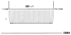
図1は、上記「端部よれ」を説明するための図であり、記録ヘッドの端部に位置するノズルが形成する記録媒体上のドットの様子を示したものである。ここでは、簡単のために最端部に位置するノズルによって記録されたドットのみが黒丸で示されているが、実際には所定色を記録する全ノズルが、1回の紙送り動作を挟んだ2回の記録走査で100%の記録を行った状態を示している。図で示した紙送り境界とは、2つの記録走査の境界部を示しており、このラインの上側に示したドット列は、第1の記録走査で最下端のノズルによって記録されたドット列である。また、ラインの下側に示したドット列は、続く第2の記録走査で最上端のノズルによって記録されたドット列を示している。適用した記録ヘッドは、4plのインク滴を吐出可能なノズルを、1200dpiのピッチで256個配列した構成とし、図の左から右に向かって移動しながら所定の駆動周波数でインクを吐出することによって各ドットを記録媒体に着弾させたものとする。図で確認できるように、端部のノズルによって記録されたドット、すなわち2つの記録走査の最上端と最下端のノズルで記録されるドットは、記録走査開始時には互いに接した好適な位置に着弾しているが、走査が進むに連れて徐々に着弾位置がずれ始め、最終的には、2つのノズルによる着弾位置の距離は約50μm程まで離れてしまっている。 FIG. 1 is a diagram for explaining the above-mentioned “edge shift”, and shows the state of dots on a recording medium formed by nozzles positioned at the end of the recording head. Here, for the sake of simplicity, only dots recorded by the nozzle located at the extreme end are indicated by black circles, but in reality, all the nozzles that record a predetermined color sandwich one paper feeding operation. A state where 100% printing is performed by two printing scans is shown. The paper feed boundary shown in the figure indicates the boundary between two print scans, and the dot row shown above the line is a dot row printed by the lowermost nozzle in the first print scan. is there. A dot row shown below the line indicates a dot row recorded by the uppermost nozzle in the subsequent second recording scan. The applied recording head has a configuration in which 256 nozzles capable of ejecting 4 pl ink droplets are arranged at a pitch of 1200 dpi, and ejects ink at a predetermined driving frequency while moving from left to right in the figure. It is assumed that each dot has landed on the recording medium. As can be seen in the figure, the dots recorded by the nozzles at the end, that is, the dots recorded by the uppermost and lowermost nozzles of the two recording scans, land at suitable positions in contact with each other at the start of the recording scan. However, as the scanning progresses, the landing position gradually begins to shift, and finally the distance between the landing positions of the two nozzles is about 50 μm.
図2は、上記のような記録走査を行っている際の、記録ヘッドの吐出状態を模式的に示した図である。図2において、記録ヘッドは紙面垂直方向に移動走査しながら各ノズルより記録媒体に向けて矢印の方向にインク滴を吐出している。図に見るように、記録ヘッドの両端部に位置するノズルから吐出されるインク滴は、中央部に向けて偏向された状態で進んでいることがわかる。こうした傾向は、4plあるいはこれ以下の極小のインク滴によって画像を形成する場合、また記録デューティが高い場合に顕著に現れる。そして、この記録走査ごとに現れるドットのよれが、視覚特性上、白スジとして認知されてしまうのである。 FIG. 2 is a diagram schematically showing the ejection state of the recording head when performing the recording scanning as described above. In FIG. 2, the recording head ejects ink droplets in the direction of the arrow from each nozzle toward the recording medium while moving and scanning in the direction perpendicular to the paper surface. As can be seen from the figure, the ink droplets ejected from the nozzles located at both ends of the recording head proceed while being deflected toward the center. Such a tendency is conspicuous when an image is formed with a very small ink droplet of 4 pl or less, and when the recording duty is high. Then, the dot that appears in each recording scan is recognized as a white stripe in terms of visual characteristics.
このような画像弊害に対し、上述したマルチパス記録を適用したり、マルチパス数を通常より多く設定したりすることによって、白スジをより目立たなくすることも可能である。しかしながら、近年求められるような写真画質と同等な品位の画像を得るにはこのような対策は十分とは言えなかった。また、マルチパス数を更に増やすことは、記録走査の回数を増大させるので、高速化を阻害してしまうことにもなる。 It is also possible to make white stripes less noticeable by applying the above-described multi-pass recording or setting the number of multi-passes more than usual for such image defects. However, such a measure has not been sufficient for obtaining an image having a quality equivalent to that of a photographic image as required in recent years. Further, further increasing the number of multi-passes increases the number of printing scans, and therefore hinders speeding up.
以上の問題に対し、必要以上にマルチパス数を増大させずに端部近傍のノズルに因る画像弊害を低減するために、ノズル列を所定のピッチで複数のブロック(記録素子群)に分割し、分割された各ブロックに対する間引き率を、互いに異なる値に設定する方法が知られている(例えば、特許文献4参照。)。この方法によれば、例えば図9(a)に示すようなマスクパターンを適用することにより、1回の記録走査で形成される領域において、両端部に位置するノズルの記録率を予め小さく設定することが出来る。よって、ずれた位置に着弾されるドットの数が抑えられるので、図1で説明したような白スジも確認されなくなるのである。 To solve the above problems, the nozzle array is divided into a plurality of blocks (recording element groups) at a predetermined pitch in order to reduce the image damage caused by the nozzles near the end without increasing the number of multi-passes more than necessary. A method of setting the thinning rate for each divided block to a different value is known (for example, see Patent Document 4). According to this method, for example, by applying a mask pattern as shown in FIG. 9A, the recording rate of the nozzles located at both ends in the region formed by one recording scan is set to be small in advance. I can do it. Therefore, since the number of dots that are landed at the shifted position is suppressed, the white streaks described with reference to FIG. 1 are not confirmed.
しかしながら、上記従来例では以下のような解決すべき課題があった。
まず、記録ヘッドのノズル列内で記録率の分布が均等でないと、温度の偏りが生じ、濃度ムラを発生する恐れがある。記録率の高いブロックと低いブロックが同一記録ヘッド内で存在すると、記録率の高いブロックでは相対的に温度が高くなり、そのブロックのみ吐出量が大きくなってしまう。すなわち、記録ヘッド内に吐出量のばらつきが発生し、記録した画像においてはこれが濃度ムラとして現れてしまうのである。特に近年では、記録速度を向上させるために、ノズル数の増大化、記録ヘッドの長尺化が図られており、記録ヘッドの温度を一様に保つ制御が難しくなって来ている。このような状況の中で、より温度分布の不均一を促進するような上記制御は、濃度ムラの観点からは好ましい制御とは言い難かった。
However, the above conventional example has the following problems to be solved.
First, if the recording rate distribution is not uniform within the nozzle array of the recording head, temperature deviation may occur and density unevenness may occur. If a block with a high recording rate and a block with a low recording rate are present in the same recording head, the temperature of the block with a high recording rate will be relatively high, and the ejection amount will increase only for that block. That is, variations in the discharge amount occur in the recording head, and this appears as density unevenness in the recorded image. Particularly in recent years, in order to improve the recording speed, the number of nozzles has been increased and the length of the recording head has been increased, making it difficult to control the temperature of the recording head uniformly. Under such circumstances, the above control that promotes the non-uniformity of the temperature distribution has been difficult to say from the viewpoint of density unevenness.
また、記録率分布の不均一性は、ノズル間に吐出回数の格差を生じさせる。この場合、吐出回数の多いノズルは、吐出特性の劣化が他のノズルに比べて早い時期に進んでしまう。記録ヘッドにおいては、ノズルが一つでも吐出不良となったときに、使用が不適当と判断されるので、局所的に一部のノズルの記録頻度が高い特許文献4に記載の方法は、記録ヘッドの寿命を短くしてしまうことに繋がる。
Further, the nonuniformity of the recording rate distribution causes a difference in the number of ejections between the nozzles. In this case, the nozzle having a large number of ejections proceeds earlier in the deterioration of the ejection characteristics than the other nozzles. In the recording head, when even one nozzle has an ejection failure, it is determined that the use is inappropriate. Therefore, the method described in
以上説明したように、小液滴の記録ヘッドを用いる近年のインクジェット記録装置においては、濃度ムラや記録ヘッドの寿命の観点から、ノズル列の吐出回数をなるべく均一に保つことが好ましいと言える。しかし、その一方で、従来技術の項で説明したような「端部よれ」の問題も同時に抱えている。よって、両者の問題を一気に解決する方法が望まれる。 As described above, in a recent ink jet recording apparatus using a small droplet recording head, it can be said that it is preferable to keep the number of ejections of the nozzle rows as uniform as possible from the viewpoint of density unevenness and the life of the recording head. However, on the other hand, it also has the problem of “shaft edge” as explained in the section of the prior art. Therefore, a method for solving both problems at once is desired.
特許文献5によれば、記録ヘッドの使用量に応じて、ノズルの記録率の分布を切り換える方法が開示されている。この方法によれば、ノズル列に対する記録率の分布が異なる複数のマスクパターンを予め用意しておきながら、記録ヘッドの使用量または耐久回数に応じて、適用するマスクパターンを切り替える。よって、長期的な観点から見れば、各ノズルの吐出回数をほぼ均等化することが出来、記録ヘッドの寿命の問題についてある程度解決することが可能となる。
According to
しかしながら、上記複数のマスクパターンの切り替えは、同一画像、同一ページを記録している最中に行われることはないので、各記録走査内に存在するノズル間の吐出量差を軽減することは出来ない。すなわち、もう一つの問題である濃度ムラを同時に解決するためには、より短期的な観点で各ノズルの吐出回数を均等化する必要があるが、これに対し特許文献5による方法では解決しきれていなかったのである。 However, since the switching of the plurality of mask patterns is not performed during the recording of the same image and the same page, it is possible to reduce the discharge amount difference between the nozzles existing in each recording scan. Absent. In other words, in order to simultaneously solve another problem of density unevenness, it is necessary to equalize the number of ejections of each nozzle from a short-term viewpoint. It was not.
本発明は上記問題点を解決するために成されたものであり、その目的とするところは、小液滴のインクを吐出する記録素子を多数配列した記録ヘッドを用いながら、濃度ムラや白スジの少ない、一様性に優れた記録を行い、記録ヘッドの寿命も必要以上に短縮されないインクジェット記録システムを提供することである。 The present invention has been made to solve the above-described problems. The object of the present invention is to achieve density unevenness and white streak while using a recording head in which a large number of recording elements for discharging small droplets of ink are arranged. It is an object of the present invention to provide an ink jet recording system that performs recording with less uniformity and excellent uniformity and does not unnecessarily shorten the life of the recording head.
そのために本発明においては、インクを吐出する複数の記録素子から構成される記録素子群を所定方向に複数配列してなる記録ヘッドを用い、記録媒体の同一領域に対して異なる記録素子群による前記所定方向とは異なる方向への複数回の記録走査によって画像を形成するインクジェット記録システムにおいて、前記複数の記録素子群が互いに異なる記録率に従ってインクを吐出する手段と、前記記録走査ごとに前記複数の記録素子群の内の少なくとも2つの記録素子群における記録率を変更する記録率変更手段と、を具備することを特徴とする。 Therefore, in the present invention, a recording head in which a plurality of recording element groups each including a plurality of recording elements that eject ink is arranged in a predetermined direction is used. In an inkjet recording system for forming an image by a plurality of recording scans in a direction different from a predetermined direction, the plurality of recording element groups eject ink according to different recording rates, and the plurality of the plurality of recording elements for each recording scan Recording rate changing means for changing the recording rate in at least two recording element groups in the recording element group.
また、インクを吐出する複数の記録素子から構成される記録素子群を所定方向に複数配列してなる記録ヘッドを用い、記録媒体の同一領域に対して異なる記録素子群による前記所定方向とは異なる方向への複数回の記録走査によって画像を形成するインクジェット記録システムにおいて、前記複数の記録素子群の内の、ある記録素子群と別の記録素子群が互いに異なる記録率に従ってインクを吐出する手段と、前記複数回の記録走査のうち、ある記録走査と別の記録走査とで、前記複数の記録素子群の内の少なくとも2つの記録素子群における記録率を変更する記録率変更手段と、を具備することを特徴とする。 Also, a recording head formed by arranging a plurality of recording element groups composed of a plurality of recording elements for ejecting ink in a predetermined direction differs from the predetermined direction by different recording element groups for the same region of the recording medium. In an ink jet recording system for forming an image by a plurality of recording scans in a direction, means for ejecting ink in accordance with a different recording rate from one recording element group and another recording element group in the plurality of recording element groups; A recording rate changing means for changing a recording rate in at least two recording element groups of the plurality of recording element groups between one recording scan and another recording scan among the plurality of recording scans. It is characterized by doing.
また、インクを吐出する複数の記録素子から構成される記録素子群を所定方向に複数配列してなる記録ヘッドを用い、記録媒体の同一領域に対して異なる記録素子群による前記所定方向とは異なる方向への複数回の記録走査によって画像を形成するインクジェット記録システムにおいて、前記複数の記録素子群それぞれが異なる記録率に従ってインクを吐出する手段と、前記複数回の記録走査のうち、ある記録走査と別の記録走査とで、前記複数の記録素子群それぞれに対応する記録率の前記所定方向における分布を変更する記録率変更手段と、を具備することを特徴とする。 Also, a recording head formed by arranging a plurality of recording element groups composed of a plurality of recording elements for ejecting ink in a predetermined direction differs from the predetermined direction by different recording element groups for the same region of the recording medium. In the ink jet recording system for forming an image by a plurality of recording scans in the direction, the plurality of recording element groups each eject ink according to a different recording rate, and among the plurality of recording scans, a certain recording scan Recording rate changing means for changing the distribution in the predetermined direction of the recording rate corresponding to each of the plurality of recording element groups in another recording scan.
また、インクを吐出する複数の記録素子から構成される記録素子群を所定方向に複数配列してなる記録ヘッドを用い、記録媒体の同一領域に対して異なる記録素子群による前記所定方向とは異なる方向への複数回の記録走査によって画像を形成するインクジェット記録システムにおいて、前記複数の記録素子群が互いに異なるマスクパターンに従ってインクを吐出する手段と、前記記録走査ごとに前記複数の記録素子群それぞれのマスクパターンを変更するマスクパターン変更手段とを具備し、前記マスクパターン変更手段は、前記異なる記録素子群のうちの少なくとも2つの記録素子群について、当該記録素子群に対応するマスクパターンの記録率を変更することを特徴とする。 Also, a recording head formed by arranging a plurality of recording element groups composed of a plurality of recording elements for ejecting ink in a predetermined direction differs from the predetermined direction by different recording element groups for the same region of the recording medium. In an inkjet recording system for forming an image by a plurality of recording scans in the direction, the plurality of recording element groups ejects ink according to different mask patterns, and each of the plurality of recording element groups for each recording scan A mask pattern changing means for changing a mask pattern, wherein the mask pattern changing means has a mask pattern recording rate corresponding to the recording element group for at least two recording element groups of the different recording element groups. It is characterized by changing.
本発明によれば、複数の異なる記録素子群で構成される記録素子列において、端部よれが発生しがちな両端部に位置する記録素子群の記録率を低減させておきながら、記録中の吐出回数を各記録素子群で極力均等化させることが出来る。これにより、記録ヘッドの寿命を必要以上に短縮させずに、濃度ムラの原因となる温度分布の偏りや白スジの原因となる端部よれを低減することが可能となる。 According to the present invention, in a recording element array composed of a plurality of different recording element groups, while reducing the recording rate of the recording element groups located at both end portions where the end portion is liable to be generated, The number of ejections can be made as uniform as possible in each recording element group. As a result, it is possible to reduce the uneven temperature distribution that causes density unevenness and the edge portion that causes white stripes without shortening the life of the recording head more than necessary.
以下に、本発明に適用可能なインクジェット記録システムの構成例を具体的に説明する。
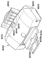
図3は、本発明に適用可能なインクジェット記録装置の概観構成を説明するための図である。図3において、インクジェット記録装置本体M1000の外郭は、下ケースM1001、上ケースM1002、アクセスカバーM1003および排出トレイM1004を含む外装部材と、その外装部材内に収納されたシャーシM3019(図4参照)とから構成される。
Hereinafter, a configuration example of an ink jet recording system applicable to the present invention will be specifically described.
FIG. 3 is a view for explaining the general configuration of an ink jet recording apparatus applicable to the present invention. In FIG. 3, the outer periphery of the ink jet recording apparatus main body M1000 includes an exterior member including a lower case M1001, an upper case M1002, an access cover M1003, and a discharge tray M1004, and a chassis M3019 (see FIG. 4) housed in the exterior member. Consists of
シャーシM3019は、所定の剛性を有する複数の板状金属部材によって構成され、記録装置の骨格をなし、後述の各記録動作機構を保持するものとなっている。また、下ケースM1001は装置本体M1000の外装の略下半部を、上ケースM1002は装置本体M1000の外装の略上半部をそれぞれ形成しており、両ケースの組合せによって内部に後述の各機構を収納する収納空間を有する中空体構造をなしている。装置本体M1000の上面部及び前面部には、それぞれ、開口部が形成されている。 The chassis M3019 is composed of a plurality of plate-shaped metal members having a predetermined rigidity, forms a skeleton of the recording apparatus, and holds each recording operation mechanism described later. The lower case M1001 forms a substantially lower half part of the exterior of the apparatus main body M1000, and the upper case M1002 forms a substantially upper half part of the exterior of the apparatus main body M1000. The hollow body structure which has the storage space which stores the. An opening is formed in each of the upper surface portion and the front surface portion of the apparatus main body M1000.
排出トレイM1004は、その一端部が下ケースM1001に回動自在に保持され、その回動によって下ケースM1001の前面部に形成される開口部を開閉させ得るようになっている。このため、記録動作を実行させる際には、排出トレイM1004を前面側へと回動させて開口部を開成させることにより、ここから記録媒体が排出可能となると共に排出された記録媒体を順次積載し得るようになっている。また、排紙トレイM1004には、2枚の補助トレイM1004aおよびM1004bが収納されており、必要に応じて各トレイを手前に引き出すことにより、記録媒体の支持面積を3段階に拡大、縮小させ得るようになっている。 One end of the discharge tray M1004 is rotatably held by the lower case M1001, and the opening formed on the front surface of the lower case M1001 can be opened and closed by the rotation. Therefore, when executing the recording operation, the discharge tray M1004 is rotated to the front side to open the opening, so that the recording medium can be discharged from the recording medium and the discharged recording media are sequentially stacked. It has come to be able to do. The paper discharge tray M1004 stores two auxiliary trays M1004a and M1004b, and the support area of the recording medium can be expanded or reduced in three stages by pulling each tray forward as necessary. It is like that.
アクセスカバーM1003は、その一端部が上ケースM1002に回動自在に保持され、上面に形成される開口部を開閉し得るようになっており、アクセスカバーM1003を開くことによって本体内部に収納されている記録ヘッドカートリッジH1000あるいはインクタンクH1900等の交換が可能となる。なお、ここでは特に図示しないが、アクセスカバーM1003を開閉させると、その裏面に形成された突起がカバー開閉レバーを回転させるようになっており、そのレバーの回転位置をマイクロスイッチなどで検出することにより、アクセスカバーM1003の開閉状態を検出し得るようになっている。 One end of the access cover M1003 is rotatably held by the upper case M1002, and an opening formed on the upper surface can be opened and closed. The access cover M1003 is accommodated inside the main body by opening the access cover M1003. It is possible to replace the print head cartridge H1000 or the ink tank H1900. Although not specifically shown here, when the access cover M1003 is opened and closed, the protrusion formed on the back surface rotates the cover opening and closing lever, and the rotation position of the lever is detected by a micro switch or the like. Thus, the open / closed state of the access cover M1003 can be detected.
上ケースM1002の後部上面には、電源キーE0018及びレジュームキーE0019が押下可能に設けられると共に、LED E0020が設けられており、電源キーE0018を押下すると、LED E0020が点灯し記録可能であることをオペレータに知らせるものとなっている。また、LED E0020は点滅の仕方や色が変化することにより、記録装置のトラブル等をオペレータに知らせる等種々の表示機能を有する。なお、トラブル等が解決した場合には、レジュームキーE0019を押下することによって記録が再開されるようになっている。 On the upper surface of the rear portion of the upper case M1002, a power key E0018 and a resume key E0019 are provided so that they can be pressed, and an LED E0020 is provided. When the power key E0018 is pressed, the LED E0020 lights up and recording is possible. It is to inform the operator. Further, the LED E0020 has various display functions such as notifying the operator of troubles of the recording apparatus, etc., by changing the way of blinking or the color. When the trouble is solved, the recording is resumed by pressing the resume key E0019.
図4は、装置本体M1000に収納および保持される本実施形態の記録動作機構を説明するための図である。
本実施形態における記録動作機構としては、記録媒体を装置本体内へと自動的に給送する自動給送部M3022と、自動給送部から1枚ずつ送出される記録媒体を所定の記録位置へと導くと共に、記録位置から排出部M3030へと記録媒体を導く搬送部M3029と、記録位置に搬送された記録媒体に所望の記録を行なう記録部と、記録部等に対する回復処理を行う回復部M5000とから構成されている。
FIG. 4 is a diagram for explaining the recording operation mechanism of this embodiment that is housed and held in the apparatus main body M1000.
As a recording operation mechanism in the present embodiment, an automatic feeding unit M3022 that automatically feeds a recording medium into the apparatus main body, and a recording medium that is sent one by one from the automatic feeding unit to a predetermined recording position. And a transport unit M3029 for guiding the recording medium from the recording position to the discharge unit M3030, a recording unit for performing desired recording on the recording medium transported to the recording position, and a recovery unit M5000 for performing recovery processing on the recording unit and the like. It consists of and.
搬送部M3029は、搬送モータE0001の駆動によって搬送ローラが回転され、この回転によって記録媒体が所定量ずつ排出方向に搬送させる構成となっている。 The transport unit M3029 is configured such that the transport roller is rotated by driving the transport motor E0001, and the recording medium is transported by a predetermined amount in the discharge direction by the rotation.
記録部は、キャリッジ軸M4021によって移動可能に支持されたキャリッジM4001と、キャリッジM4001に着脱可能に搭載される記録ヘッドカートリッジH1000とから構成される。キャリッジM4021は、キャリッジモータE0001によって駆動され、所定の速度で記録媒体の搬送方向と交差する方向に往復移動する。 The recording unit includes a carriage M4001 that is movably supported by a carriage shaft M4021, and a recording head cartridge H1000 that is detachably mounted on the carriage M4001. The carriage M4021 is driven by a carriage motor E0001 and reciprocates in a direction intersecting the recording medium conveyance direction at a predetermined speed.
図5は、記録ヘッドカートリッジH1000の外観を示した図である。記録ヘッドカートリッジH1000は、インクを貯留するインクタンクH1900と、インクタンクH1900から供給されるインクを記録情報に応じてノズルから吐出させる記録ヘッドH1001とから構成されている。インクタンクH1900としては、写真調の高画質なカラー記録を可能とするために、ここではブラック、ライトシアン、ライトマゼンタ、シアン、マゼンタ及びイエロー用のものが各色独立に用意されている。 FIG. 5 is a view showing the appearance of the recording head cartridge H1000. The recording head cartridge H1000 includes an ink tank H1900 that stores ink, and a recording head H1001 that discharges ink supplied from the ink tank H1900 from nozzles according to recording information. As the ink tank H1900, black, light cyan, light magenta, cyan, magenta, and yellow are prepared independently for each color in order to enable high-quality color recording with a photographic tone.
図6は、上記各色のインクタンクH1900が、記録ヘッドH1001に対して着脱自在に装着される様子を示した構成図である。このように各色のインクタンクが独立に交換可能なカートリッジ方式を採用することにより、消耗したインク色のインクタンクのみを、適宜交換することが可能となっている。 FIG. 6 is a configuration diagram showing how the ink tanks H1900 for the respective colors are detachably attached to the recording head H1001. By adopting a cartridge system in which the ink tanks of the respective colors can be independently replaced in this way, it is possible to appropriately replace only the ink tanks of the exhausted ink colors.
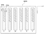
図7は、本実施形態で適用する記録ヘッドH1001を吐出口側から観察した様子を示した図である。ここでは、ブラック(K)、ライトシアン(LC)、ライトマゼンタ(LM)、シアン(C)、マゼンタ(M)およびイエロー(Y)の6色分の吐出口が図のように配置されている。各色においては、X方向に600dpi(ドット/インチ;参考値)の間隔で640個ずつ配置されている2列の吐出口列が、互いに半ピッチ(約20μm)ずれて並列配置されることにより、記録媒体には1200dpiの記録密度で画像が形成されるようになっている。各色の吐出口列は、図のようにY方向に並列しており、記録ヘッドH1001がY方向に移動しながら、所定の周波数でインクを吐出することにより、記録媒体にはフルカラーの画像が形成されるようになっている。なお、本実施形態における各記録素子は、吐出口に通じるインクの通り道となる液路と、インクに熱エネルギを与える電気熱変換体によって構成されるものとする。画像を記録する際には、画像データに応じて各記録素子の電気熱変換体に所定の電圧が印加されることにより、液室内に膜沸騰が起こり、その発泡エネルギによって、記録素子の吐出口から所定量のインク液滴が吐出されるものである。 FIG. 7 is a diagram illustrating a state in which the recording head H1001 applied in the present embodiment is observed from the ejection port side. Here, discharge ports for six colors of black (K), light cyan (LC), light magenta (LM), cyan (C), magenta (M) and yellow (Y) are arranged as shown in the figure. In each color, two ejection port arrays arranged at 640 at an interval of 600 dpi (dot / inch; reference value) in the X direction are arranged in parallel with a half-pitch (about 20 μm) shifted from each other. An image is formed on the recording medium at a recording density of 1200 dpi. The ejection port arrays for each color are arranged in parallel in the Y direction as shown in the figure, and a full color image is formed on the recording medium by ejecting ink at a predetermined frequency while the recording head H1001 moves in the Y direction. It has come to be. Note that each recording element in the present embodiment is configured by a liquid path serving as an ink passage leading to an ejection port and an electrothermal converter that gives thermal energy to the ink. When an image is recorded, a predetermined voltage is applied to the electrothermal transducer of each recording element in accordance with the image data, so that film boiling occurs in the liquid chamber, and the foaming energy causes the recording element to discharge. A predetermined amount of ink droplets is ejected from.
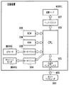
図8は、本実施形態で適用するインクジェット記録装置の制御系の概略ブロック構成を示した図である。記録装置は、ホストコンピュータ300から、記録情報を制御信号として受信する。記録情報は、記録装置内部の入出力インタフェイス301に一時保存されると同時に、記録装置内で処理可能なデータに変換され、記録ヘッド駆動信号の供給手段を兼ねるCPU302に入力される。CPU302は、ROM303に保存されている制御プログラムに基づき、CPU302に入力されたデータをRAM304等の周辺ユニットを用いて処理し、記録装置が記録可能な画像データに変換する。
FIG. 8 is a diagram showing a schematic block configuration of a control system of the ink jet recording apparatus applied in the present embodiment. The recording apparatus receives recording information as a control signal from the
また、CPU302は、画像データを記録媒体上の適当な位置に記録すべく、画像データに同期して記録媒体および記録ヘッドH1001を移動させるための駆動データを生成し、LFモータE0002やキャリッジモータE0001を駆動させる。画像データおよび各モータの駆動データは、それぞれヘッドドライバ307、モータドライバ305および306を介して、記録ヘッドH1001および各種モータに伝達され、制御されたタイミングで画像が形成される。
以上説明した本実施形態の記録装置を用い、本発明の最も特徴的な構成について、以下に具体的な実施例を説明する。
In addition, the
A specific example of the most characteristic configuration of the present invention will be described below using the recording apparatus of the present embodiment described above.
本実施例におけるインクジェット記録装置では、同一領域を複数回の記録走査で画像を形成する8パスのマルチパス記録方式を採用する。本実施例で適用するマスクパターンとしては、乱数的に画像データを間引くことにより各記録走査の記録データを不規則に決定するランダムマスクパターンと、固定的に画像データを間引くことにより各記録走査の記録データを規則的に決定する固定マスクパターンとを併用し、最終的な記録データは、両者の掛け合わせによって生成するものとする。 The ink jet recording apparatus according to the present embodiment employs an 8-pass multi-pass recording system in which an image is formed in the same region by a plurality of recording scans. The mask pattern applied in the present embodiment includes a random mask pattern that randomly determines the recording data of each recording scan by thinning out the image data randomly, and each recording scan by fixedly thinning out the image data. It is assumed that the final recording data is generated by multiplying both of them together with a fixed mask pattern for regularly determining the recording data.
図9(a)および(b)は、本実施例で適用するランダムマスクパターンAおよびBを説明するための図である。901は、記録ヘッドH1001に配列されたある1色のノズル列を示しており、ノズル列901には1280個のノズルが図の縦方向に配列しているものとする。1280個のノズルは160個ずつ8つの均等なブロック(記録素子群)に分割され、図ではそれぞれのブロックにおける記録率と、これに準じる記録画素(記録を許容する画素)が黒く塗りつぶした部分として示されている。なお、白い部分は非記録画素(画像データに関係なく、記録を許容しない画素)を示している。ここでは、図9(a)および(b)ともに、カラム方向(ノズル並び方向)に1280画素、ラスタ方向(記録ヘッド主走査方向)に512画素の計655360画素分の領域について、記録画素または非記録画素が定められたマスクパターンが用意されている。
FIGS. 9A and 9B are diagrams for explaining the random mask patterns A and B applied in the present embodiment.
ランダムマスクパターンAおよびBともに、4パスのマルチパス記録用のランダムマスクパターンとなっており、4回の記録主走査と320ノズル分ずつの副走査により、100%の画像が完成する構成となっている。より詳しく説明すると、例えばランダムマスクパターンAにおいて、第1の記録走査でブロックa1によって記録された記録媒体上の領域(例えば、領域X)は、第2記録走査ではブロックa3で、第3記録走査ではブロックa5で、第4記録走査ではブロックa7で記録される。各ブロックに対応したマスクパターンの記録画素の配列は、互いに補完し合うような、重複しない配列になっており、各ブロックの記録率10%、30%、40%および20%を合計した100%の記録が4回の記録走査によって得られるのである。a2、a4、a6、a8の関係、およびランダムマスクパターンBの各領域の関係においても同様の構成となっている。 Both the random mask patterns A and B are random mask patterns for 4-pass multi-pass printing, and 100% of the image is completed by four printing main scans and sub-scans for 320 nozzles each. ing. More specifically, for example, in the random mask pattern A, the area (for example, the area X) on the recording medium recorded by the block a1 in the first recording scan is the block a3 in the second recording scan, and the third recording scan. Is recorded in block a5, and in the fourth recording scan, recording is performed in block a7. The arrangement of the recording pixels of the mask pattern corresponding to each block is a non-overlapping arrangement that complements each other, and the total recording rate of each block is 10%, 30%, 40%, and 20%. This recording is obtained by four recording scans. The same configuration is applied to the relationship between a2, a4, a6, and a8 and the relationship between each region of the random mask pattern B.
なお「ブロックの記録率」とは、記録媒体上の所定の領域(例えば、上述した領域X)に対する記録を完成させるのに使用される複数のブロック(例えば、上述したブロックa1、a3、a5、a7)に対応したマスクパターンの全記録画素数に対する、各ブロックに対応したマスクパターンの記録画素数の割合である。例えば、ブロックa1、a3、a5、a7に対応したマスクパターンの全記録画素数は327680(=655360÷2)個となっており、ブロックa1に対応したマスクパターンの記録画素数は32768個となっている。従って、ブロックa1の記録率(もしくは、ブロックa1に対応するマスクパターンの記録率)は10(=32768/327680×100)%となる。 The “block recording rate” refers to a plurality of blocks (for example, the blocks a1, a3, a5, and the like described above) used to complete recording on a predetermined area (for example, the area X described above) on the recording medium. This is the ratio of the number of recorded pixels of the mask pattern corresponding to each block to the total number of recorded pixels of the mask pattern corresponding to a7). For example, the total number of recorded pixels of the mask pattern corresponding to the blocks a1, a3, a5, and a7 is 327680 (= 655360/2), and the number of recorded pixels of the mask pattern corresponding to the block a1 is 32768. ing. Therefore, the recording rate of the block a1 (or the recording rate of the mask pattern corresponding to the block a1) is 10 (= 32768/327680 × 100)%.
また、「記録画素」とは、上述したように記録を許容する画素のことであり、この記録画素に対応する画像データがインク吐出を示すデータであれば記録がなされ、非吐出を示すデータならば記録は行われない。一方、「非記録画素」とは、画像データに関わらず記録を許容しない画素のことであり、仮に、この非記録画素に対応する画像データがインク吐出を示すデータであっても記録はなされてない。 The “recording pixel” is a pixel that allows recording as described above. If the image data corresponding to the recording pixel is data indicating ink ejection, recording is performed. If you do not record. On the other hand, “non-recording pixels” are pixels that do not allow printing regardless of image data. Even if image data corresponding to these non-printing pixels is data indicating ink ejection, printing is performed. Absent.
ランダムマスクパターンAとランダムマスクパターンBとでは、各ブロックに対する記録率の分布が異なっており、ランダムマスクパターンAではノズル列の中央部(中央に位置するブロック)の記録率が高く、両端部(両端部それぞれに位置するブロック)の記録率が低く設定されている。また、ランダムマスクパターンBにおいてはノズル列の中央に位置するブロックの記録率はその両側に位置するブロックよりも低く設定されており、両端に位置するブロックの記録率はランダムマスクパターンAと同様に低く設定されている。図10(a)および(b)は、本実施例で適用する固定マスクパターンを説明するための図である。図10(a)および(b)ともに、図9で説明したランダムマスクと同様、カラム方向(ノズル並び方向)に1280画素、ラスタ方向(記録ヘッド主走査方向)に512画素の領域を有しているが、ここでは記録画素(記録が許容される画素)と非記録画素(記録が許容されない画素)が、1画素ずつ互い違いに位置するような配列となっている。また、図10(a)と(b)は、互いに補完の関係にあり、両者を重ね合わせることによって100%の画像が形成されるように構成されている。ここでは、図10(a)を千鳥パターン、図10(b)を逆千鳥パターンと称することとする。
本実施例において、以上4種類のマスクパターンは全てRAM304に格納されているものとする。
The random mask pattern A and the random mask pattern B have different recording rate distributions for each block, and the random mask pattern A has a high recording rate in the central portion (block located in the center) of the nozzle row, and both end portions ( The recording rate of the blocks located at both ends is set low. In the random mask pattern B, the recording rate of the block located in the center of the nozzle row is set lower than the blocks located on both sides thereof, and the recording rate of the blocks located at both ends is the same as that of the random mask pattern A. It is set low. FIGS. 10A and 10B are diagrams for explaining the fixed mask pattern applied in the present embodiment. Both FIGS. 10A and 10B have an area of 1280 pixels in the column direction (nozzle alignment direction) and 512 pixels in the raster direction (printing head main scanning direction), as in the random mask described in FIG. However, in this example, the recording pixels (pixels that allow recording) and the non-recording pixels (pixels that do not allow recording) are arranged alternately one by one. FIGS. 10A and 10B are complementary to each other, and are configured such that a 100% image is formed by superimposing both. Here, FIG. 10A is referred to as a staggered pattern, and FIG. 10B is referred to as an inverted staggered pattern.
In the present embodiment, it is assumed that the above four types of mask patterns are all stored in the
図11は、実際に記録を行う際に本実施例のCPU302が行う記録データの生成処理を説明するためのフローチャートである。なお、本実施例においては、上記4種類のマスクパターンを適用しながら、8パスのマルチパス記録を往復記録走査で行うものとする。すなわち、記録媒体上の同一領域においては、記録ヘッドによる8回の往復記録主走査と各記録主走査の間に行われる160画素分ずつの副走査によって、順次画像が形成されていくのである。
FIG. 11 is a flowchart for explaining recording data generation processing performed by the
8パスのマルチパス記録のコマンドが入力されると、まず入出力インタフェイス301よりCPU302に画像データが入力される(ステップS1001)。
When an 8-pass multi-pass printing command is input, image data is first input from the input /
ステップS1002では、変数nに−1を積算し、続くステップS1003では、nが正か負かを判断する。この結果により、次に行う記録走査が偶数回目の記録走査であるか、奇数回目の記録走査であるかを判定することが出来る。すなわちnは記録走査回数の偶数・奇数を判別するための変数であり、ここでは初期値として1が書き込まれているものとする。なお、本実施例においては、奇数回目の記録走査は往路で記録し、偶数回目の記録走査は復路で記録するようになっている。 In step S1002, −1 is added to the variable n, and in subsequent step S1003, it is determined whether n is positive or negative. Based on this result, it is possible to determine whether the next print scan is an even-numbered print scan or an odd-numbered print scan. That is, n is a variable for determining the even / odd number of printing scans, and here, it is assumed that 1 is written as an initial value. In this embodiment, odd-numbered recording scans are recorded on the forward path, and even-numbered recording scans are recorded on the backward path.
ステップS1003でn>0と判断された場合には、次の走査が偶数記録走査であると判断され、入力画像データに対し、図10(b)で示した逆千鳥パターンを掛け合わせる(ステップ1004―a)。さらにステップS1005−aでは、ステップS1004−aで得られた記録データに対し、図9(b)で示したランダムマスクパターンBを掛け合わせる。すなわち、偶数記録走査においては、逆千鳥パターンとランダムマスクパターンBによって掛け合わされた新たなマスクパターン(2)によって入力画像データが間引かれる。 If n> 0 is determined in step S1003, it is determined that the next scan is an even-numbered scan, and the input image data is multiplied by the inverted staggered pattern shown in FIG. 10B (step 1004). -A). In step S1005-a, the recording data obtained in step S1004-a is multiplied by the random mask pattern B shown in FIG. That is, in the even-number recording scan, the input image data is thinned out by the new mask pattern (2) obtained by multiplying the inverted staggered pattern and the random mask pattern B.
一方、ステップS1003でn<0と判断された場合には、次の走査が奇数記録走査であると判断され、入力画像データに対し、図10(a)で示した千鳥パターンを掛け合わせる(ステップ1004―b)。さらにステップS1005−bでは、ステップS1004−bで得られた記録データに対し、図9(a)で示したランダムマスクパターンAを掛け合わせる。すなわち、奇数記録走査においては、千鳥パターンとランダムマスクパターンAによって掛け合わされた新たなマスクパターン(1)によって入力画像データが間引かれる。 On the other hand, if n <0 is determined in step S1003, it is determined that the next scan is an odd recording scan, and the input image data is multiplied by the staggered pattern shown in FIG. 1004-b). In step S1005-b, the recording data obtained in step S1004-b is multiplied by the random mask pattern A shown in FIG. That is, in the odd recording scan, the input image data is thinned out by the new mask pattern (1) multiplied by the staggered pattern and the random mask pattern A.
以上、ステップS1004およびS1005によって、画像データとマスクパターンとの掛け合わせが終了し、次に行われる記録走査にて記録される最終的な記録データが完成する。 As described above, in steps S1004 and S1005, the multiplication of the image data and the mask pattern is completed, and the final print data recorded in the next print scan is completed.
次にステップS1006にて、CPU302は生成された記録データをヘッドドライバ307に出力し、同時にモータドライバ305および306を駆動する。ヘッドドライバ307は、入力された記録データに従い、所定のタイミングに合わせて記録ヘッドH1001を駆動する。またモータドライバ305は、LFモータE0002を駆動し、LFローラを所定量回転させる。更に、モータドライバ306は、キャリッジモータE0001を駆動し、所定の速度でキャリッジM4001を走査させる。これにより、記録ヘッドによる1回の記録走査が行われる。
In step S1006, the
ステップS1007では、記録すべき画像データの全てについて記録データの生成が終了したか否かを判断する。終了している場合には本モードを終了する。記録すべき画像データがまだ残っている場合には、ステップS1002に戻り、次の記録走査のために変数nに−1を積算する。 In step S1007, it is determined whether generation of recording data has been completed for all image data to be recorded. When it is finished, this mode is finished. If image data to be recorded still remains, the process returns to step S1002, and −1 is added to the variable n for the next recording scan.
本実施例によれば、往路で行われる奇数回目の記録走査と、復路で行われる複数回目の記録走査とで、適用するマスクパターンを、マスクパターン(1)およびマスクパターン(2)の間で切り替えながら、画像を形成していることになる。 According to this embodiment, the mask pattern to be applied between the mask pattern (1) and the mask pattern (2) in the odd-numbered printing scan performed in the forward path and the plurality of recording scans performed in the backward path is used. An image is formed while switching.
このような方法で8パスのマルチパス記録を行った場合、各記録走査間では160画素ずつの副走査が行われるため、ある往路の記録走査から次の往路の記録走査の間には、320画素分の副走査が行われていることになる。すなわち、往路の記録走査のみで考えると、4パスのマルチパス記録が行われていることになる。往路の記録走査では、ランダムマスクパターンAと千鳥パターンの掛け合わせによって決定されたマスクパターン(1)が用いられているが、ランダムマスクパターンAは4パスのマルチパス記録によって、100%の記録が行われる構成となっているので、結果的に往路の4パス記録によって、千鳥パターンの50%画像が形成されることになる。 When 8-pass multi-pass printing is performed in this way, sub-scans of 160 pixels are performed between print scans, so that 320 scans are performed between one print pass and the next print scan. Sub-scanning for pixels is performed. That is, considering only the forward printing scan, four-pass multi-pass printing is performed. In the forward recording scan, the mask pattern (1) determined by multiplying the random mask pattern A and the staggered pattern is used, but the random mask pattern A is recorded by 100% by 4-pass multi-pass recording. As a result, a 50% image of a staggered pattern is formed by the four-pass printing on the outward path.
このような構成は、復路の記録走査についても同様である。復路の記録走査では、ランダムマスクパターンBと逆千鳥パターンの掛け合わせによって決定されたマスクパターン(2)が用いられているが、ランダムマスクパターンBは4パスのマルチパス記録によって、100%の記録が行われる構成となっているので、結果的に復路の4パス記録によって、逆千鳥パターンの50%画像が形成されることになる。 Such a configuration is the same for the printing scan in the backward path. In the backward scanning scan, the mask pattern (2) determined by the multiplication of the random mask pattern B and the reverse staggered pattern is used, but the random mask pattern B is recorded at 100% by 4-pass multi-pass printing. As a result, a 50% image of an inverted staggered pattern is formed by four-pass printing on the return path.
以上より、往路の4パス記録によって千鳥パターンが、復路の4パス記録によって逆千鳥パターンがそれぞれ記録されるが、千鳥パターンと逆千鳥パターンは図10で説明したように互いに補完の関係にある。よって、最終的には、往路の記録走査と復路の記録走査とが互いに補完しあうことにより100%の画像が完成されるようになっている。 As described above, the zigzag pattern is recorded by the four-pass recording on the forward path, and the reverse zigzag pattern is recorded by the four-pass recording on the return path. Therefore, finally, 100% of the image is completed by complementing the forward recording scan and the backward recording scan.
以上のような構成によれば、往路の記録走査と復路の記録走査とで、それぞれ50%ずつの記録率となっているので、往路における記録ヘッドの吐出回数と、復路における記録ヘッドの吐出回数を、略同等に保つことが出来る。しかしながら、記録ヘッド上に配列する各ノズルの吐出回数の分布は、図9で説明した各ブロックの記録率分布に依存することになり、往路と復路ではその分布の仕方が大きく異なっていることがわかる。すなわち、往路ではノズル列の中心近傍に位置するブロックa4およびブロックa5の吐出回数が最も高くなっているが、復路ではブロックa2およびブロックa7の吐出回数が最も高く設定されている。 According to the above configuration, since the recording rate is 50% for each of the forward recording scan and the backward recording scan, the number of ejections of the recording head in the outward path and the number of ejections of the recording head in the backward path are as follows. Can be kept approximately the same. However, the distribution of the number of ejections of each nozzle arranged on the recording head depends on the recording rate distribution of each block described with reference to FIG. 9, and the way of distribution differs greatly between the forward path and the backward path. Understand. That is, in the forward path, the number of ejections of the block a4 and the block a5 located in the vicinity of the center of the nozzle row is the highest, but in the backward path, the number of ejections of the block a2 and the block a7 is set to be the highest.
上述した「端部よれ」の対策として記録ヘッドの両端部すなわちブロックa1およびa8の記録率を他のブロックに比べて低く設定することが効果的であることは既に述べた。その一方で、例えばマスクパターンAのみを適用した記録を行っていると、ブロックa4およびブロックa5における温度が、他のブロックに比べて局所的に上昇し、濃度ムラの原因となってしまうことも説明した。本実施例の構成によれば、このような状況を踏まえた上で、記録走査ごとに記録率の分布が異なる記録方法を実現している。従って、記録ヘッド内の温度分布を略一様に保つことが可能となるのである。 As described above, it is effective to set the recording rate of both ends of the recording head, that is, the blocks a1 and a8, lower than those of the other blocks as a countermeasure against the above-mentioned “end-to-end”. On the other hand, for example, when recording using only the mask pattern A is performed, the temperature in the block a4 and the block a5 is locally increased as compared with other blocks, which may cause density unevenness. explained. According to the configuration of the present embodiment, in consideration of such a situation, a recording method in which the distribution of the recording rate differs for each recording scan is realized. Therefore, the temperature distribution in the recording head can be kept substantially uniform.
図12(a)は、本実施例で示したマスクパターンを適用して記録した画像と、従来の方法によって記録した画像との目視による評価結果を説明するための図である。ここで、従来の方法とは、記録ヘッドに配列する1280個のノズル列を本実施例と同様に8分割し、各ブロックの記録率を端部より、5%、10%、15%、20%、20%、15%、10%、5%としたマスクパターンを用いて8パス双方向のマルチパス記録を行ったものとする。 FIG. 12A is a diagram for explaining the visual evaluation results of an image recorded by applying the mask pattern shown in this embodiment and an image recorded by a conventional method. Here, in the conventional method, 1280 nozzle rows arranged in the print head are divided into 8 as in this embodiment, and the print rate of each block is 5%, 10%, 15%, 20 from the end. It is assumed that 8-pass bidirectional multi-pass printing is performed using mask patterns of%, 20%, 15%, 10%, and 5%.
図12(a)において、評価項目は、記録ヘッドの耐久寿命、吐出量のばらつきに起因した濃度ムラおよび端部よれに起因した白スジの3項目としている。 In FIG. 12A, the evaluation items are three items, that is, the durable life of the recording head, the density unevenness caused by the variation in the discharge amount, and the white stripe caused by the edge portion.
耐久寿命の評価は、耐久用のベタ画像を所定枚数連続して記録し、記録開始直前と記録終了直後に評価用のテスト画像を記録することにより行った。このような検討を、本実施例のマスク、従来例のマスク、および各分割ブロックで均一に12.5%の記録率を有するマスクをそれぞれ適用した場合について行い、記録開始直前と記録終了直後のテスト画像の間で急激な吐出特性劣化(例えば、不吐出、濃度ムラ、スジムラ等)が発生した時点を、各マスクパターンにおける記録ヘッドの寿命と判断した。そして、この時点における全ノズルによる吐出数の総数を、各マスクについて算出し、本実施例および従来例については、得られた総数を12.5%の均一マスクを用いた場合の総数で除算し、その値に100を乗算した。すなわち表には、均一マスクを適用した場合の寿命を100とした場合の、それぞれのマスクの寿命が記載されていることになり、値が100に近づくほど評価が高い(寿命が長い)ことを示している。 Evaluation of the endurance life was performed by recording a predetermined number of solid images for durability continuously and recording test images for evaluation immediately before the start of recording and immediately after the end of recording. Such a study is performed in the case where the mask of this embodiment, the mask of the conventional example, and the mask having a recording rate of 12.5% uniformly in each divided block are applied. The point in time at which sudden discharge characteristic deterioration (for example, non-discharge, density unevenness, uneven stripes, etc.) occurred between test images was determined as the life of the recording head in each mask pattern. Then, the total number of ejections by all nozzles at this time is calculated for each mask, and for this example and the conventional example, the total number obtained is divided by the total number when a uniform mask of 12.5% is used. The value was multiplied by 100. That is, in the table, the lifetime of each mask is described when the lifetime when a uniform mask is applied is set to 100, and the evaluation is higher as the value approaches 100 (the lifetime is longer). Show.
表によれば、本実施例のマスクを用いた場合が83.3、従来例のマスクを用いた場合が62.5となっており、本実施例のほうが従来例よりも記録ヘッドの寿命が長いことが判る。これは、本実施例を適用した場合、走査毎にマスクパターンが入れ替えられるので、記録ヘッドの各ブロックにおいて記録率が集中せず、特定の記録素子のみが特別早く劣化することが無いためである。これに対し、従来例においては、記録素子列の中央部分を使用する頻度が常に高いために、中央部分のみの劣化が促進され、結果として記録ヘッドの寿命を早めてしまっているのである。 According to the table, 83.3 is obtained when the mask of this embodiment is used, and 62.5 is obtained when the mask of the conventional example is used, and the life of the recording head in this embodiment is longer than that of the conventional example. I understand that it is long. This is because when the present embodiment is applied, the mask pattern is replaced for each scanning, so that the recording rate is not concentrated in each block of the recording head, and only a specific recording element does not deteriorate particularly quickly. . On the other hand, in the conventional example, since the frequency of using the central portion of the printing element array is always high, deterioration of only the central portion is promoted, and as a result, the life of the recording head is shortened.
濃度ムラおよび白スジの評価は、各色の記録ヘッドで100%のベタ画像を、各マスクパターンを用いて8パス記録した後、色毎に評価を行い、更に6色の評価結果の平均を採ったものである。評価点は、◎、〇、△、×、××、の5段階としており、◎〜〇は目視にて各弊害が判別不能なレベル、△は明視距離30cmにて確認可能なレベル、×〜××は明視距離1mにおいても確認可能なレベルとした。 Density unevenness and white stripes were evaluated by recording 100% solid images with each color recording head for 8 passes using each mask pattern, then evaluating each color, and taking the average of the evaluation results for 6 colors. It is a thing. The evaluation points are ◎, ○, △, ×, XX, where ◎ to ○ are levels at which each harmful effect cannot be discerned visually, △ is a level that can be confirmed at a visual distance of 30 cm, × ˜XX is a level that can be confirmed even at a clear visual distance of 1 m.
濃度ムラに関しては、本実施例の評価が◎、従来例が×となっている。これは、本実施例を適用した場合、走査毎にマスクパターンが入れ替えられるので、記録ヘッドの各ブロックで記録率が集中せず、局所的な温度上昇が起こりにくくなっているからである。 Regarding density unevenness, the evaluation of this example is ◎, and the conventional example is ×. This is because when the present embodiment is applied, the mask pattern is changed for each scan, so that the recording rate is not concentrated in each block of the recording head, and local temperature rise is unlikely to occur.
具体的には、往路走査で最も記録率の高いブロックは、図9(a)で示したブロックa4とブロックa5となり、それぞれ図10(a)で示した千鳥マスクと掛け合わせることにより、20%の記録率となっている。このままの状態で復路走査も同様のマスクを用いて記録を続けると、ブロックa4およびa5には常に記録率の高い状態が保持されるので、他のブロックに比べ温度が上昇しやすくなり、吐出量が増大して濃度ムラの原因となる。しかしながら、本実施例の復路走査においては、ブロックa4およびa5の記録率は10%となっており、より端部に位置するブロックa2およびa7の記録率が20%となるので、温度が上昇しやすいブロックが移行され、ノズル列の吐出量のばらつきも均等化されるのである。これに対し従来例では、往路走査および復路走査ともにブロックa4およびa5の記録率が20%に保たれたままなので、ノズル列の中央部が局所的に高温となり、この部分のみ吐出量が増大して濃度ムラを発生してしまう。 Specifically, the blocks with the highest recording rate in the forward scanning are the block a4 and the block a5 shown in FIG. 9A, and are multiplied by the staggered mask shown in FIG. The recording rate is. If recording is continued using the same mask for the backward scan in this state, the blocks a4 and a5 always maintain a high recording rate, so the temperature is likely to rise compared to the other blocks, and the discharge amount Increases and causes density unevenness. However, in the backward scan of the present embodiment, the recording rate of the blocks a4 and a5 is 10%, and the recording rate of the blocks a2 and a7 located at the end is 20%, so the temperature rises. Easy blocks are transferred, and variations in the discharge amount of the nozzle rows are equalized. On the other hand, in the conventional example, since the printing rate of the blocks a4 and a5 is kept at 20% for both the forward scanning and the backward scanning, the central portion of the nozzle row is locally high in temperature, and the discharge amount increases only in this portion. Density unevenness.
白スジに関しては、本実施例のマスクパターンと従来例のマスクパターンともに、最端部の2つのブロックにおける記録率が他のブロックより低い値に設定されている。よって、端部よれに起因した白スジは目立ちにくい傾向にある。しかしながら、本実施例におけるマスクパターンのうち、ランダムマスクパターンBを用いた復路走査では、最端部の記録ブロックa1およびa8に隣接したブロックa2およびa7の記録率が最も高くなっている。このように記録率の格差が大きい部分では、均一なマスクを適用した際の最端部と類似した条件が備わるため、細かい白スジが発生しやすい。従って、全てなだらかなグラデーションのマスクを適用している従来例に比べ、本実施例の白スジ評価では、若干レベルの低い○レベルとなった。 Regarding white stripes, both the mask pattern of this embodiment and the mask pattern of the conventional example are set so that the recording rate of the two blocks at the extreme ends is lower than that of the other blocks. Therefore, white streaks due to the edge twist tend not to stand out. However, in the backward scanning using the random mask pattern B among the mask patterns in the present embodiment, the recording rates of the blocks a2 and a7 adjacent to the recording blocks a1 and a8 at the end are highest. In such a portion where the difference in recording rate is large, a condition similar to that at the end when a uniform mask is applied is provided, so that fine white stripes are likely to occur. Therefore, compared to the conventional example in which all the gentle gradation masks are applied, the white streak evaluation of this example is a slightly lower level.
以下に、本発明の第2の実施例を説明する。本実施例においても、実施例1と同様に図3〜図8を用いて説明した構成の記録装置を適用するものとし、同一領域を8回の記録走査で画像を形成する8パスのマルチパス記録方式を採用する。また、適用するマスクパターンにおいても、実施例1と同様に、乱数的に画像データを間引くことにより各記録走査の記録データを不規則に決定するランダムマスクパターンと、固定的に画像データを間引くことにより各記録走査の記録データを規則的に決定する固定マスクパターンとを併用し、最終的な記録データは、両者の掛け合わせによって生成するものとする。 The second embodiment of the present invention will be described below. Also in this embodiment, the printing apparatus having the configuration described with reference to FIGS. 3 to 8 is applied as in the first embodiment, and an 8-pass multi-pass for forming an image in the same area by 8 printing scans. Adopt recording method. In addition, in the mask pattern to be applied, similarly to the first embodiment, the image data is randomly thinned out, and the random mask pattern for irregularly determining the print data of each print scan and the image data are fixedly thinned out. Thus, a fixed mask pattern for regularly determining print data of each print scan is used together, and final print data is generated by multiplying the two.
図13(a)および(b)は、本実施例で適用するランダムマスクパターンCおよびDを説明するための図である。901は、実施例1と同様、記録ヘッドH1001に配列されたある1色のノズル列を示しており、ノズル列901には縦方向に1280個のノズルが配列しているものとする。1280個のノズルは160個ずつ8つの均等なブロックに分割され、図ではそれぞれのブロックにおける記録率とこれに準じる記録画素が黒く塗りつぶした部分として示されている。ここでは、図13(a)および(b)ともに、カラム方向(ノズル並び方向)に1280画素、ラスタ方向(記録ヘッド主走査方向)に512画素の計655360画素分の領域について、記録画素または非記録画素が定められたマスクパターンが用意されている。
FIGS. 13A and 13B are diagrams for explaining the random mask patterns C and D applied in the present embodiment.
ランダムマスクパターンCおよびDともに、実施例1と同様、4パスのマルチパス記録用のランダムマスクパターンとなっており、4回の記録主走査と320ノズル分ずつの副走査により、100%の画像が完成する構成となっている。 Both random mask patterns C and D are random mask patterns for 4-pass multi-pass printing as in Example 1, and 100% of the image is obtained by four main printing scans and 320 sub-scans. Is completed.
ランダムマスクパターンCとランダムマスクパターンDとでは、各ブロックに対する記録率の分布が互いに異なっている。両マスクともに最両端部の記録率は10%と低く設定されているが、ランダムマスクパターンCでは、紙送り方向に対し比較的先頭側のブロックa2およびa3の記録率が高くなっており、ランダムマスクパターンDでは、紙送り方向に対し比較的後側のブロックa6およびa7の記録率が高くなっている。 The random mask pattern C and the random mask pattern D have different recording rate distributions for each block. In both masks, the recording rate at the outermost ends is set as low as 10%. However, in the random mask pattern C, the recording rate of the blocks a2 and a3 on the relatively leading side with respect to the paper feed direction is relatively high. In the mask pattern D, the recording rate of the blocks a6 and a7 on the relatively rear side with respect to the paper feeding direction is high.
実施例1と同様、往路走査ではランダムマスクパターンCと千鳥パターンとの掛け合わせにより得られるマスクパターン(3)、復路走査ではンダムマスクパターンDと逆千鳥パターンとの掛け合わせにより得られるマスクパターン(4)を用いて、それぞれ記録を行う。 As in the first embodiment, the mask pattern (3) obtained by multiplying the random mask pattern C and the staggered pattern in the forward scan, and the mask pattern (by masking the random mask pattern D and the inverted staggered pattern in the backward scan) Recording is performed using 4).
図12(b)は、本実施例を適用して記録した画像と、従来の方法によって記録した画像との目視による評価結果を、実施例1による図12(a)と同様に説明するための図である。 FIG. 12B illustrates the visual evaluation results of the image recorded by applying the present embodiment and the image recorded by the conventional method in the same manner as FIG. 12A of the first embodiment. FIG.
記録ヘッドの寿命に関しては、本実施例のマスクを用いた場合が83.3、従来例のマスクを用いた場合が62.5と、実施例1と同様の結果が得られている。本実施例を適用した場合にも、各ブロックの記録率を記録走査ごとに分散させることが出来るので、特定の記録素子のみが劣化することを防止することが出来るためである。 Regarding the life of the recording head, 83.3 is obtained when the mask of this embodiment is used, and 62.5 is obtained when the mask of the conventional example is used. This is because even when the present embodiment is applied, the recording rate of each block can be dispersed for each recording scan, so that only a specific recording element can be prevented from deteriorating.
また、濃度ムラに関しても、本実施例の評価が◎で従来例が×と、実施例1と同様の結果が得られている。本実施例を適用した場合にも、走査毎にマスクパターンが入れ替えられるので、記録ヘッドの各ブロックにおいては記録率が集中せず、局所的な温度上昇が起こりにくい。特に本実施例においては、均等なマスクを利用していた場合にも温度の高くなりがちな中央部において、記録率が高くなることは無く、比較的温度の上がりにくい両端部に位置するブロックにおいて、記録率の高い状態の記録走査を交互に行っているので、記録ヘッド全体の温度の均一性という観点では、より好ましい状態が得られ、吐出量ばらつきは殆ど発生していない状態が得られたのである。 Further, regarding the density unevenness, the evaluation of this example is ◎, the conventional example is x, and the same result as that of Example 1 is obtained. Even when this embodiment is applied, the mask pattern is changed for each scanning, so that the recording rate is not concentrated in each block of the recording head, and a local temperature rise hardly occurs. In particular, in this embodiment, even in the case where a uniform mask is used, in the central portion where the temperature tends to be high, the recording rate does not increase, and the blocks located at both ends where the temperature is relatively difficult to rise. In addition, since the recording scan with a high recording rate is alternately performed, a more preferable state is obtained from the viewpoint of the uniformity of the temperature of the entire recording head, and a state in which there is almost no variation in the discharge amount is obtained. It is.
白スジに関しては、実施例1よりも高い評価の◎が得られている。これは、「端部よれ」の原因が、記録率の高い領域に近く位置している場合に、より顕著に現れることによるものである。つまり、本実施例における両端部のブロックは、記録率40%のブロックと隣接する記録走査と、記録率40%のブロックとは640画素程度の距離を置いて位置する記録走査とが交互に行われる構成となっている。これに対し、実施例1における両端部のブロックは、記録率40%のブロックと隣接する記録走査と、320画素程度の距離を置いて位置する記録走査とが交互に行われる構成となっており、平均して考えると、本実施例の両端部のブロックのほうが、高い記録率のブロック(ここでは記録率40%のブロック)と比較的距離が置かれている状態が保たれていることになるのである。従って、本実施例の構成のほうが、評価が高い結果が得られているのである。
Regarding white streaks, ◎ of higher evaluation than Example 1 is obtained. This is due to the fact that the cause of “swinging edge” appears more prominently when it is located close to a region with a high recording rate. That is, in the blocks at both ends in this embodiment, the recording scan adjacent to the block with the recording rate of 40% and the recording scan positioned at a distance of about 640 pixels are alternately performed with the block with the recording rate of 40%. It is the composition that is called. On the other hand, the blocks at both ends in the first embodiment are configured such that a recording scan adjacent to a block with a recording rate of 40% and a recording scan positioned at a distance of about 320 pixels are alternately performed. On average, the blocks at both ends of this embodiment are kept relatively far away from the higher recording rate block (here, the
以上2つの実施例を挙げて説明したように、本発明によれば、記録素子列の各ブロックの記録率が互いに異なる分布を持つマスクパターンを、往路走査と復路走査著で切り替えながら適用することにより、記録ヘッドの寿命を必要以上に短縮させずに、濃度ムラや白スジの少ない滑らかな画像を得ることが可能となった。 As described above with reference to the two embodiments, according to the present invention, the mask patterns having different distributions of the recording rates of the respective blocks of the printing element array can be applied while switching between the forward scanning and the backward scanning. As a result, it is possible to obtain a smooth image with less density unevenness and white stripes without shortening the life of the recording head more than necessary.
なお、以上の実施例においては、例えばランダムマスクパターンAと千鳥パターン、またランダムマスクパターンBと逆千鳥パターンの4種類のマスクパターンを、記録装置内のROM303に格納しておき、各記録走査でそれぞれの掛け合わせを行う構成で説明したが、本発明はこれに限定されるものではない。それぞれのマスクの掛け合わせは、記録開始のコマンドが受信された時点で行ってしまい、記録中は作成された2つのマスクパターンを交互に読み出すことによって、1ページ分の記録を行うものであってもよい。また、ROM303には、例えば実施例1であれば、ランダムマスクパターンAと千鳥パターンによって作成されるマスクパターン(1)と、ランダムマスクパターンBと逆千鳥パターンによって作成されるマスクパターン(2)の2つが予め格納されている構成であってもよい。この場合、格納するマスクパターンの種類を2種類に抑えることが出来るので、上述した構成よりも少ないメモリで本発明を実現することができる。但し、上記実施例で説明した様に、互いに掛け合わせて使用する数種類のマスクパターンを格納しておくことは、例えばランダムマスクパターンAと逆千鳥パターンとの掛け合わせなど、別の組み合わせによって更に多くのマスクパターンを生成することが出来るので、記録モードに応じてマスクを切り替えたい場合などには、有効な構成手段とも言えるのである。
In the above embodiment, four types of mask patterns, for example, a random mask pattern A and a staggered pattern, and a random mask pattern B and an inverted staggered pattern are stored in the
また、適用したマスクパターンA、B、CおよびDの各ブロックに対応した部分の記録率も、図9または図13に示した値に限定されるものではない。更に、固定マスクとして図10に示したマスクパターンにおいても、千鳥パターンや逆千鳥パターンに限定されるものではない。マルチパス数や各ブロックの記録率、ランダム性を持たせるか否かのようなパターン配列の特徴などは、記録ヘッドの特性、記録モード、記録媒体などによって適宜設定されれば良く、高い記録率を有するブロックが、記録走査毎に入れ替えられる構成であれば、本発明の効果は得られるものである。 Further, the recording rate of the portion corresponding to each block of the applied mask patterns A, B, C and D is not limited to the values shown in FIG. 9 or FIG. Furthermore, the mask pattern shown in FIG. 10 as the fixed mask is not limited to the staggered pattern or the reverse staggered pattern. The characteristics of the pattern arrangement such as the number of multipasses, the recording rate of each block, and whether or not to have randomness may be set as appropriate depending on the characteristics of the recording head, the recording mode, the recording medium, etc. The effect of the present invention can be obtained if the block having the is replaced every recording scan.
更に、上記実施例では、往路走査と復路走査でマスクパターンを切り替えながら画像を形成する双方向記録による画像形成方法を例に説明してきたが、本発明はこれに限定されるものでもない。片方向のマルチパス記録であっても、奇数走査と偶数走査のように、記録走査単位でマスクパターンを切り替える構成であれば、本発明の範囲に含まれるものである。 Furthermore, in the above-described embodiment, the image forming method by bidirectional recording in which an image is formed while switching the mask pattern between the forward scan and the backward scan has been described as an example, but the present invention is not limited to this. Even in the case of unidirectional multi-pass printing, any configuration in which the mask pattern is switched in units of printing scan, such as odd-numbered scanning and even-numbered scanning, is included in the scope of the present invention.
更にまた、以上の実施例においては、図8のブロック図を用いて説明したように、適用するマスクの格納場所およびマスクの掛け合わせ処理などを、記録装置内部のメモリを利用して行う構成で説明してきたが、本発明はこれに限定されるものでもない。例えば図8で示した記録装置の外部装置として接続されるホストコンピュータ300に、上記のような機能を有するような構成とし、マスクの保存、マスクの掛け合わせ、更に画像データに対しマスクパターンを掛けるなどの一連の作業を、全てホストコンピュータ300によって行うような構成にした場合でも、本発明の記録システムとしての効果はなんら変わるものではない。
Furthermore, in the above embodiment, as described with reference to the block diagram of FIG. 8, the storage location of the mask to be applied and the mask multiplication processing are performed using the memory inside the printing apparatus. Although described, the present invention is not limited to this. For example, the
本発明は、複数の記録素子よりインクを吐出して画像を形成するシリアル型のインクジェット記録システムに適用することが出来る。 The present invention can be applied to a serial type ink jet recording system that forms an image by ejecting ink from a plurality of recording elements.
300 ホストコンピュータ
301 入出力インタフェイス
302 CPU
303 ROM
304 モータドライバ
305 モータドライバ
307 ヘッドドライバ
901 ノズル列
M1000 装置本体
M1001 下ケース
M1002 上ケース
M1003 アクセスカバー
M1004 排出トレイ
M3019 シャーシ
M3022 自動給送部
M3029 搬送部
M3030 排出部
M4001 キャリッジ
M4021 キャリッジ軸
M5000 回復部
E0001 キャリッジモータ
E0002 LFモータ
E0018 電源キー
E0019 リジュームキー
E0020 LED
H1000 記録ヘッドカートリッジ
H1001 記録ヘッド
H1900 インクタンク
300
303 ROM
304
H1000 recording head cartridge H1001 recording head H1900 ink tank
Claims (12)
前記複数の記録素子群が互いに異なる記録率に従ってインクを吐出する手段と、
前記記録走査ごとに前記複数の記録素子群の内の少なくとも2つの記録素子群における記録率を変更する記録率変更手段と、
を具備することを特徴とするインクジェット記録システム。 Using a recording head formed by arranging a plurality of recording element groups composed of a plurality of recording elements for ejecting ink in a predetermined direction, in a direction different from the predetermined direction by different recording element groups for the same region of the recording medium. In an inkjet recording system for forming an image by a plurality of recording scans,
Means for ejecting ink in accordance with different recording rates for the plurality of recording element groups;
A recording rate changing means for changing a recording rate in at least two recording element groups of the plurality of recording element groups for each recording scan;
An ink jet recording system comprising:
前記記録率変更手段は、前記複数の記録素子群のうち、前記所定方向の両端部に位置する記録素子群の記録率をその内側に隣接する記録素子群の記録率よりも小なる値に設定することを特徴とする請求項1乃至3のいずれかに記載のインクジェット記録システム。 In the recording head, the plurality of recording elements constituting the recording element group are arranged in the same direction as the predetermined direction,
The recording rate changing means sets a recording rate of a recording element group located at both ends in the predetermined direction among the plurality of recording element groups to a value smaller than a recording rate of a recording element group adjacent to the inside. The ink jet recording system according to claim 1, wherein the ink jet recording system is an ink jet recording system.
前記複数の記録素子群の内の、ある記録素子群と別の記録素子群が互いに異なる記録率に従ってインクを吐出する手段と、
前記複数回の記録走査のうち、ある記録走査と別の記録走査とで、前記複数の記録素子群の内の少なくとも2つの記録素子群における記録率を変更する記録率変更手段と、
を具備することを特徴とするインクジェット記録システム。 Using a recording head formed by arranging a plurality of recording element groups composed of a plurality of recording elements for ejecting ink in a predetermined direction, in a direction different from the predetermined direction by different recording element groups for the same region of the recording medium. In an inkjet recording system for forming an image by a plurality of recording scans,
Means for ejecting ink in accordance with a recording rate at which one recording element group and another recording element group among the plurality of recording element groups differ from each other;
A recording rate changing means for changing a recording rate in at least two recording element groups of the plurality of recording element groups in one recording scan and another recording scan among the plurality of recording scans;
An ink jet recording system comprising:
前記複数の記録素子群それぞれが異なる記録率に従ってインクを吐出する手段と、
前記複数回の記録走査のうち、ある記録走査と別の記録走査とで、前記複数の記録素子群それぞれに対応する記録率の前記所定方向における分布を変更する記録率変更手段と、を具備することを特徴とするインクジェット記録システム。 Using a recording head formed by arranging a plurality of recording element groups composed of a plurality of recording elements for ejecting ink in a predetermined direction, in a direction different from the predetermined direction by different recording element groups for the same region of the recording medium. In an inkjet recording system for forming an image by a plurality of recording scans,
Means for ejecting ink according to different recording rates for each of the plurality of recording element groups;
Recording rate changing means for changing a distribution in a predetermined direction of a recording rate corresponding to each of the plurality of recording element groups between a certain recording scan and another recording scan among the plurality of recording scans. An ink jet recording system.
前記複数の記録素子群が互いに異なるマスクパターンに従ってインクを吐出する手段と、
前記記録走査ごとに前記複数の記録素子群それぞれのマスクパターンを変更するマスクパターン変更手段とを具備し、
前記マスクパターン変更手段は、前記異なる記録素子群のうちの少なくとも2つの記録素子群について、当該記録素子群に対応するマスクパターンの記録率を変更することを特徴とするインクジェット記録システム。 Using a recording head formed by arranging a plurality of recording element groups composed of a plurality of recording elements for ejecting ink in a predetermined direction, in a direction different from the predetermined direction by different recording element groups for the same region of the recording medium. In an inkjet recording system for forming an image by a plurality of recording scans,
Means for ejecting ink according to different mask patterns for the plurality of recording element groups;
Mask pattern changing means for changing the mask pattern of each of the plurality of printing element groups for each printing scan,
The ink jet recording system, wherein the mask pattern changing unit changes a recording rate of a mask pattern corresponding to the recording element group for at least two recording element groups of the different recording element groups.
前記マスクパターン変更手段は、前記複数の記録素子群のうち、前記所定方向の両端部に位置する記録素子群に対して該記録素子群の内側に隣接する記録素子群よりも低い記録率のマスクパターンを対応させることを特徴とする請求項8乃至10のいずれかに記載のインクジェット記録システム。 In the recording head, the plurality of recording elements constituting the recording element group are arranged in the same direction as the predetermined direction,
The mask pattern changing means is a mask having a lower recording rate than the recording element group adjacent to the inside of the recording element group with respect to the recording element group located at both ends in the predetermined direction among the plurality of recording element groups. The inkjet recording system according to claim 8, wherein the pattern is made to correspond.
12. The ink jet recording system according to claim 8, wherein the mask pattern is newly generated by synthesizing a plurality of mask patterns stored in advance in a storage unit.
Priority Applications (1)
| Application Number | Priority Date | Filing Date | Title |
|---|---|---|---|
| JP2003417365A JP2005177992A (en) | 2003-12-15 | 2003-12-15 | Inkjet recording system |
Applications Claiming Priority (1)
| Application Number | Priority Date | Filing Date | Title |
|---|---|---|---|
| JP2003417365A JP2005177992A (en) | 2003-12-15 | 2003-12-15 | Inkjet recording system |
Publications (2)
| Publication Number | Publication Date |
|---|---|
| JP2005177992A true JP2005177992A (en) | 2005-07-07 |
| JP2005177992A5 JP2005177992A5 (en) | 2007-01-11 |
Family
ID=34779880
Family Applications (1)
| Application Number | Title | Priority Date | Filing Date |
|---|---|---|---|
| JP2003417365A Pending JP2005177992A (en) | 2003-12-15 | 2003-12-15 | Inkjet recording system |
Country Status (1)
| Country | Link |
|---|---|
| JP (1) | JP2005177992A (en) |
Cited By (9)
| Publication number | Priority date | Publication date | Assignee | Title |
|---|---|---|---|---|
| JP2007176165A (en) * | 2005-12-01 | 2007-07-12 | Canon Inc | Method of generating recording data, recording apparatus and method of generating mask |
| JP2010140090A (en) * | 2008-12-09 | 2010-06-24 | Canon Inc | Image data processing apparatus, image forming device, and image data processing method |
| US7878613B2 (en) | 2005-12-01 | 2011-02-01 | Canon Kabushiki Kaisha | Print data generation method, printing apparatus and method of generating mask |
| US8342649B2 (en) | 2010-08-20 | 2013-01-01 | Canon Kabushiki Kaisha | Printing apparatus and printing method |
| JP2013094734A (en) * | 2011-11-01 | 2013-05-20 | Seiko Epson Corp | Printed matter and printing method |
| US8936334B2 (en) | 2012-07-05 | 2015-01-20 | Seiko Epson Corporation | Printing method and printing device |
| JP2016124215A (en) * | 2015-01-05 | 2016-07-11 | セイコーエプソン株式会社 | Printer and printing method |
| JP2020082708A (en) * | 2018-11-30 | 2020-06-04 | 株式会社リコー | Liquid discharge device, discharge adjustment method, and discharge adjustment program |
| US10719746B2 (en) | 2017-12-05 | 2020-07-21 | Canon Kabushiki Kaisha | Printing apparatus, printing method, and storage medium |
-
2003
- 2003-12-15 JP JP2003417365A patent/JP2005177992A/en active Pending
Cited By (10)
| Publication number | Priority date | Publication date | Assignee | Title |
|---|---|---|---|---|
| JP2007176165A (en) * | 2005-12-01 | 2007-07-12 | Canon Inc | Method of generating recording data, recording apparatus and method of generating mask |
| US7878613B2 (en) | 2005-12-01 | 2011-02-01 | Canon Kabushiki Kaisha | Print data generation method, printing apparatus and method of generating mask |
| JP2010140090A (en) * | 2008-12-09 | 2010-06-24 | Canon Inc | Image data processing apparatus, image forming device, and image data processing method |
| US8342649B2 (en) | 2010-08-20 | 2013-01-01 | Canon Kabushiki Kaisha | Printing apparatus and printing method |
| JP2013094734A (en) * | 2011-11-01 | 2013-05-20 | Seiko Epson Corp | Printed matter and printing method |
| US8936334B2 (en) | 2012-07-05 | 2015-01-20 | Seiko Epson Corporation | Printing method and printing device |
| JP2016124215A (en) * | 2015-01-05 | 2016-07-11 | セイコーエプソン株式会社 | Printer and printing method |
| US10719746B2 (en) | 2017-12-05 | 2020-07-21 | Canon Kabushiki Kaisha | Printing apparatus, printing method, and storage medium |
| JP2020082708A (en) * | 2018-11-30 | 2020-06-04 | 株式会社リコー | Liquid discharge device, discharge adjustment method, and discharge adjustment program |
| JP7206862B2 (en) | 2018-11-30 | 2023-01-18 | 株式会社リコー | Liquid ejection device, ejection adjustment method, and ejection adjustment program |
Similar Documents
| Publication | Publication Date | Title |
|---|---|---|
| JP5038076B2 (en) | Inkjet recording apparatus and inkjet recording method | |
| JP7036179B2 (en) | Inkjet recording device and inkjet recording method | |
| JP2004058284A (en) | Inkjet recording method and inkjet recorder | |
| JP6095398B2 (en) | Recording apparatus and recording method | |
| JP2005169754A (en) | Ink jet recorder and ink jet recording method | |
| JP2007331122A (en) | Inkjet recording head and inkjet recorder | |
| JP2005199696A (en) | Ink-jet recording device, ink-jet recording method and recording head | |
| JP5152222B2 (en) | Image data processing apparatus, liquid ejection apparatus, and program | |
| JP2004074510A (en) | Recorder and test pattern recording method | |
| JP2005177991A (en) | Inkjet recording device and inkjet recording method | |
| JP5339801B2 (en) | Image processing apparatus and image processing method | |
| EP1790485B1 (en) | Inkjet recording device and inkjet recording method | |
| JP2016074152A (en) | Recording device and driving method for the same | |
| JP6397299B2 (en) | Recording apparatus and recording head drive control method | |
| JP4979485B2 (en) | Inkjet recording device | |
| JP2005177992A (en) | Inkjet recording system | |
| JP5094514B2 (en) | Inkjet recording apparatus and inkjet recording method | |
| JP5224968B2 (en) | Inkjet recording apparatus and inkjet recording method | |
| JP2008307722A (en) | Recording device and recording method | |
| JP2007038671A (en) | Inkjet recording device and inkjet recording method | |
| JP2017087731A (en) | Image processing device and image processing method | |
| JP2009061774A (en) | Inkjet recorder and inkjet recording method | |
| JP2011042048A (en) | Image processor, recording apparatus, and image processing method | |
| JP2006168111A (en) | Inkjet recording device | |
| JP2017177338A (en) | Droplet discharge controller, droplet discharge control method, and droplet discharge device |
Legal Events
| Date | Code | Title | Description |
|---|---|---|---|
| A521 | Written amendment |
Free format text: JAPANESE INTERMEDIATE CODE: A523 Effective date: 20061121 |
|
| A621 | Written request for application examination |
Free format text: JAPANESE INTERMEDIATE CODE: A621 Effective date: 20061121 |
|
| A977 | Report on retrieval |
Effective date: 20090309 Free format text: JAPANESE INTERMEDIATE CODE: A971007 |
|
| A131 | Notification of reasons for refusal |
Free format text: JAPANESE INTERMEDIATE CODE: A131 Effective date: 20090327 |
|
| A521 | Written amendment |
Effective date: 20090526 Free format text: JAPANESE INTERMEDIATE CODE: A523 |
|
| A131 | Notification of reasons for refusal |
Free format text: JAPANESE INTERMEDIATE CODE: A131 Effective date: 20090623 |
|
| A521 | Written amendment |
Free format text: JAPANESE INTERMEDIATE CODE: A523 Effective date: 20090824 |
|
| A02 | Decision of refusal |
Effective date: 20091218 Free format text: JAPANESE INTERMEDIATE CODE: A02 |