JP5091651B2 - Radar apparatus and target azimuth measurement method - Google Patents
Radar apparatus and target azimuth measurement method Download PDFInfo
- Publication number
- JP5091651B2 JP5091651B2 JP2007323068A JP2007323068A JP5091651B2 JP 5091651 B2 JP5091651 B2 JP 5091651B2 JP 2007323068 A JP2007323068 A JP 2007323068A JP 2007323068 A JP2007323068 A JP 2007323068A JP 5091651 B2 JP5091651 B2 JP 5091651B2
- Authority
- JP
- Japan
- Prior art keywords
- target
- radar apparatus
- time
- signal processing
- signal
- Prior art date
- Legal status (The legal status is an assumption and is not a legal conclusion. Google has not performed a legal analysis and makes no representation as to the accuracy of the status listed.)
- Active
Links
Images


Classifications
-
- G—PHYSICS
- G01—MEASURING; TESTING
- G01S—RADIO DIRECTION-FINDING; RADIO NAVIGATION; DETERMINING DISTANCE OR VELOCITY BY USE OF RADIO WAVES; LOCATING OR PRESENCE-DETECTING BY USE OF THE REFLECTION OR RERADIATION OF RADIO WAVES; ANALOGOUS ARRANGEMENTS USING OTHER WAVES
- G01S5/00—Position-fixing by co-ordinating two or more direction or position line determinations; Position-fixing by co-ordinating two or more distance determinations
- G01S5/02—Position-fixing by co-ordinating two or more direction or position line determinations; Position-fixing by co-ordinating two or more distance determinations using radio waves
- G01S5/04—Position of source determined by a plurality of spaced direction-finders
-
- G—PHYSICS
- G01—MEASURING; TESTING
- G01S—RADIO DIRECTION-FINDING; RADIO NAVIGATION; DETERMINING DISTANCE OR VELOCITY BY USE OF RADIO WAVES; LOCATING OR PRESENCE-DETECTING BY USE OF THE REFLECTION OR RERADIATION OF RADIO WAVES; ANALOGOUS ARRANGEMENTS USING OTHER WAVES
- G01S13/00—Systems using the reflection or reradiation of radio waves, e.g. radar systems; Analogous systems using reflection or reradiation of waves whose nature or wavelength is irrelevant or unspecified
- G01S13/02—Systems using reflection of radio waves, e.g. primary radar systems; Analogous systems
- G01S13/06—Systems determining position data of a target
- G01S13/42—Simultaneous measurement of distance and other co-ordinates
- G01S13/44—Monopulse radar, i.e. simultaneous lobing
- G01S13/4454—Monopulse radar, i.e. simultaneous lobing phase comparisons monopulse, i.e. comparing the echo signals received by an interferometric antenna arrangement
-
- G—PHYSICS
- G01—MEASURING; TESTING
- G01S—RADIO DIRECTION-FINDING; RADIO NAVIGATION; DETERMINING DISTANCE OR VELOCITY BY USE OF RADIO WAVES; LOCATING OR PRESENCE-DETECTING BY USE OF THE REFLECTION OR RERADIATION OF RADIO WAVES; ANALOGOUS ARRANGEMENTS USING OTHER WAVES
- G01S7/00—Details of systems according to groups G01S13/00, G01S15/00, G01S17/00
- G01S7/02—Details of systems according to groups G01S13/00, G01S15/00, G01S17/00 of systems according to group G01S13/00
- G01S7/35—Details of non-pulse systems
- G01S7/352—Receivers
-
- G—PHYSICS
- G01—MEASURING; TESTING
- G01S—RADIO DIRECTION-FINDING; RADIO NAVIGATION; DETERMINING DISTANCE OR VELOCITY BY USE OF RADIO WAVES; LOCATING OR PRESENCE-DETECTING BY USE OF THE REFLECTION OR RERADIATION OF RADIO WAVES; ANALOGOUS ARRANGEMENTS USING OTHER WAVES
- G01S13/00—Systems using the reflection or reradiation of radio waves, e.g. radar systems; Analogous systems using reflection or reradiation of waves whose nature or wavelength is irrelevant or unspecified
- G01S13/02—Systems using reflection of radio waves, e.g. primary radar systems; Analogous systems
- G01S13/06—Systems determining position data of a target
- G01S13/08—Systems for measuring distance only
- G01S13/32—Systems for measuring distance only using transmission of continuous waves, whether amplitude-, frequency-, or phase-modulated, or unmodulated
- G01S13/34—Systems for measuring distance only using transmission of continuous waves, whether amplitude-, frequency-, or phase-modulated, or unmodulated using transmission of continuous, frequency-modulated waves while heterodyning the received signal, or a signal derived therefrom, with a locally-generated signal related to the contemporaneously transmitted signal
- G01S13/348—Systems for measuring distance only using transmission of continuous waves, whether amplitude-, frequency-, or phase-modulated, or unmodulated using transmission of continuous, frequency-modulated waves while heterodyning the received signal, or a signal derived therefrom, with a locally-generated signal related to the contemporaneously transmitted signal using square or rectangular modulation, e.g. diplex radar for ranging over short distances
-
- G—PHYSICS
- G01—MEASURING; TESTING
- G01S—RADIO DIRECTION-FINDING; RADIO NAVIGATION; DETERMINING DISTANCE OR VELOCITY BY USE OF RADIO WAVES; LOCATING OR PRESENCE-DETECTING BY USE OF THE REFLECTION OR RERADIATION OF RADIO WAVES; ANALOGOUS ARRANGEMENTS USING OTHER WAVES
- G01S13/00—Systems using the reflection or reradiation of radio waves, e.g. radar systems; Analogous systems using reflection or reradiation of waves whose nature or wavelength is irrelevant or unspecified
- G01S13/88—Radar or analogous systems specially adapted for specific applications
- G01S13/93—Radar or analogous systems specially adapted for specific applications for anti-collision purposes
- G01S13/931—Radar or analogous systems specially adapted for specific applications for anti-collision purposes of land vehicles
- G01S2013/932—Radar or analogous systems specially adapted for specific applications for anti-collision purposes of land vehicles using own vehicle data, e.g. ground speed, steering wheel direction
-
- G—PHYSICS
- G01—MEASURING; TESTING
- G01S—RADIO DIRECTION-FINDING; RADIO NAVIGATION; DETERMINING DISTANCE OR VELOCITY BY USE OF RADIO WAVES; LOCATING OR PRESENCE-DETECTING BY USE OF THE REFLECTION OR RERADIATION OF RADIO WAVES; ANALOGOUS ARRANGEMENTS USING OTHER WAVES
- G01S13/00—Systems using the reflection or reradiation of radio waves, e.g. radar systems; Analogous systems using reflection or reradiation of waves whose nature or wavelength is irrelevant or unspecified
- G01S13/88—Radar or analogous systems specially adapted for specific applications
- G01S13/93—Radar or analogous systems specially adapted for specific applications for anti-collision purposes
- G01S13/931—Radar or analogous systems specially adapted for specific applications for anti-collision purposes of land vehicles
- G01S2013/9321—Velocity regulation, e.g. cruise control
-
- G—PHYSICS
- G01—MEASURING; TESTING
- G01S—RADIO DIRECTION-FINDING; RADIO NAVIGATION; DETERMINING DISTANCE OR VELOCITY BY USE OF RADIO WAVES; LOCATING OR PRESENCE-DETECTING BY USE OF THE REFLECTION OR RERADIATION OF RADIO WAVES; ANALOGOUS ARRANGEMENTS USING OTHER WAVES
- G01S7/00—Details of systems according to groups G01S13/00, G01S15/00, G01S17/00
- G01S7/02—Details of systems according to groups G01S13/00, G01S15/00, G01S17/00 of systems according to group G01S13/00
- G01S7/35—Details of non-pulse systems
- G01S7/352—Receivers
- G01S7/356—Receivers involving particularities of FFT processing
Landscapes
- Engineering & Computer Science (AREA)
- Radar, Positioning & Navigation (AREA)
- Remote Sensing (AREA)
- Physics & Mathematics (AREA)
- General Physics & Mathematics (AREA)
- Computer Networks & Wireless Communication (AREA)
- Radar Systems Or Details Thereof (AREA)
Description
本発明は、連続的な電波を用いて障害物を検知するレーダ装置及びターゲットの方位角計測方法に係り、特に、検知物の位置と、自車に対する相対速度とを高精度に計測する車載型レーダ装置及びターゲットの方位角計測方法に関する。 The present invention relates to a radar device that detects an obstacle using continuous radio waves and a method for measuring an azimuth angle of a target, and more particularly, an in-vehicle type that measures the position of a detected object and a relative speed with respect to a host vehicle with high accuracy. The present invention relates to a radar apparatus and a method for measuring an azimuth angle of a target.
レーダ装置を使用して、検知すべきターゲット(検知物体)の方位角を計測する方式にはいくつかの方式がある。代表的なものとして、例えば特許文献1に開示されているスキャン方式と、例えば特許文献2に開示されているモノパルス方式がある。
There are several methods for measuring the azimuth angle of a target (detected object) to be detected using a radar apparatus. As a typical example, there are a scan system disclosed in
特許文献1に開示されているスキャン方式の原理を、図14を用いて説明する。図14はレーダのアンテナ300とそのアンテナで生成される放射ビームパターン302の1例を示している。この図で示されるようにアンテナ素子を横方向に複数並べることでビームパターンを細く絞り、その放射ビームを左右方向に振る。レーダでは放射電波がターゲットで反射して戻ってくる電波の強度を計測し、その受信強度が強い方位角方向にターゲットが存在していることがわかる。
The principle of the scanning method disclosed in
次に、特許文献2には、2つのアンテナを用いるモノパルス方式、すなわち、1個の送信アンテナと、対向してすなわち互いの左右位置に配置された2個の受信アンテナ(左)および受信アンテナ(右)により構成されるアンテナを備えたレーダ構造が開示されている。
Next,
一方、特許文献3には、広角化、高感度化により検出点数が増加しても効率よく物体を追跡することができるようにした車両周辺監視装置が開示されている。すなわち、特許文献3の車両周辺監視装置は、過去に検出した各物体について、過去の物体位置データから今回検出されるべき位置を推定する物体位置推定手段と、物体の推定位置のまわりに所定のウィンドウを設けるウィンドウ設定手段と、ウィンドウ内に含まれる検出点データを用いて今回の物体位置データを求め、過去に検出した物体位置データを用いて、物体の相対速度を算出する物体追跡手段とを備えている。
On the other hand,
また、特許文献4には、対照障害物の位置推定精度を向上させた車両における対照障害物の位置推定方法が開示されている。すなわち、特許文献4の位置推定方法によれば、座標上で相互に近接する障害物データに同一ラベルを付すようにして各障害物データのラベル付けを行ない、前回のデータおよび今回のデータに基づいて各ラベル毎に移動方向および移動量を算出し、その移動量をサンプリング時間で除して自車に対する各ラベル毎の相対速度を算出し、その相対速度および前記移動方向から定まる相対速度ベクトルに基づいて所定時間後の対照障害物の位置を推定している。
自動車で走行時に障害物や前方走行車までの距離や方位角を計測するために、ミリ波を利用したレーダ装置が広く利用されている。レーダ装置は電波を放射し、障害物や前方走行車両などの物体からの反射波を受信する。そして、受信した反射波の強弱、周波数のドップラーシフト、電波の発射から反射波の受信までの伝搬時間などを検出し、その結果から物体までの距離や方位角、相対速度などを計測する。近年では、このようなレーダ装置を自動車に搭載し、障害物や先行車を検出し、その結果に基づいて運転制御をおこなう定速走行装置や車間距離制御装置が実用化されている。 Radar devices using millimeter waves are widely used to measure the distance and azimuth to obstacles and forward vehicles when traveling in an automobile. The radar device emits radio waves and receives reflected waves from an object such as an obstacle or a vehicle traveling ahead. Then, the intensity of the received reflected wave, the Doppler shift of the frequency, the propagation time from the emission of the radio wave to the reception of the reflected wave, etc. are detected, and the distance, azimuth, relative speed, etc. to the object are measured from the result. In recent years, a constant speed traveling device and an inter-vehicle distance control device have been put into practical use in which such a radar device is mounted on an automobile, an obstacle or a preceding vehicle is detected, and operation control is performed based on the result.
特許文献1に開示されたスキャン方式では、以下2つの問題が存在する。まず一つ目は放射ビームを細く絞るためにアンテナの面積が大きくなるので、レーダ装置全体の小型化が困難なことである。2つ目は、レーダのアンテナ部分を左右に動かす機械的な稼動部が必要となるため、長期信頼性の確保が困難なことである。
The scanning method disclosed in
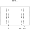
次に、特許文献2で採用されているモノパルス方式の原理を、図15(15A,15B),図16(16A,16B)を用いて説明する。まず図15Aはアンテナの構成例を示した図である。各アンテナはパッチアンテナを用いて構成されている。送信アンテナ3は1つのチャンネルから成るのに対し、受信アンテナは4(a)と4(b)の二つのチャンネルから構成される。図15Bに示すように、受信アンテナ4(a)、4(b)間の間隔をDとすると、受信アンテナ4(a)、4(b)で受信されるターゲットからの2つの反射信号は、Dsinθの位相差を有する。
Next, the principle of the monopulse method employed in
2つのチャンネルで受信された電力の和信号(Sum)の方位角依存強度と差信号(Diff)の方位角依存強度は図16Aのようになり、また、それらの比率(Ratio)を計算すると図16Bのようになる。ここで方位角θは、レーダ正面方向をθ=0、右方向への開き角度を正(+)、左方向への開き角度を負(−)と定義している。レーダごとに前記方位角依存性のデータを予め測定しておく。そして受信信号を信号処理してターゲットが検出された場合、和信号と差信号の電力の比率(Ratio)及び位相差を計測し、前記の方位角依存性のデータを参照することにより、検知ターゲットの方位角(θ)を特定できる。 The azimuth angle dependent strength of the sum signal (Sum) of the power received by the two channels and the azimuth angle dependent strength of the difference signal (Diff) are as shown in FIG. 16A, and the ratio (Ratio) is calculated. It becomes like 16B. Here, the azimuth angle θ is defined as θ = 0 for the radar front direction, positive (+) for the rightward opening angle, and negative (−) for the leftward opening angle. The azimuth-dependent data is measured in advance for each radar. And when the target is detected by signal processing of the received signal, the power ratio (Ratio) and phase difference of the sum signal and the difference signal are measured, and the detected target is referred to by referring to the azimuth angle dependency data. Can be specified.
このモノパルス方式を実施する際の重要な考え方は、レーダが異なる電波受信パターンを2つ有することである。上記のように受信アンテナを2チャンネル横に並べた場合は、左右方向にずれた2つの受信パターンを有することに相当し、それぞれのチャンネルにより取得された信号の差異を利用して方位角位置を求めている。このモノパルス方式では機械的な稼動部がなく、また電波放射パターンを細く絞る必要がないため、小型・低コスト化を図りやすい。 An important idea when implementing this monopulse system is that the radar has two different radio wave reception patterns. When the reception antennas are arranged side by side as described above, this corresponds to having two reception patterns shifted in the left-right direction, and the azimuth angle position is determined by utilizing the difference between signals acquired by the respective channels. Looking for. In this monopulse system, there is no mechanical working part, and it is not necessary to narrow down the radio wave radiation pattern, so that it is easy to reduce the size and cost.
上記モノパルス方式を利用したレーダ装置を用いて、ターゲットの方位角を正しく計測できる場合と、正しく計測できない場合とを、図17A、図17Bを用いて説明する。ここで前記レーダ装置は、ターゲットの距離と速度を計測するために、例えば2周波CW方式を採用しているものとする。 The case where the azimuth angle of the target can be correctly measured and the case where the azimuth angle of the target cannot be measured correctly using the radar apparatus using the monopulse method will be described with reference to FIGS. 17A and 17B. Here, it is assumed that the radar apparatus employs, for example, a two-frequency CW method in order to measure the distance and speed of the target.
まず、図17Aでは自車両80はレーダ装置81を搭載して走行している。車両90は計測すべきターゲットである。車両90で反射して戻ってきた受信信号の周波数は2つの車両の速度差に応じたドップラーシフト周波数となっている。このドップラーシフト周波数を有する信号の位相を計測することで、前方車両90までの距離や方位角を正しく計測することができる。
First, in FIG. 17A, the
次に図17Bのように前方に2車両が存在し、さらにその2車両の自車に対する相対速度が同一である場合を考える。この状況ではそれぞれの車両で反射して戻ってくる受信信号のドップラーシフト周波数は同じ値となるため、周波数スペクトルを観測した場合、両者の周波数ピークは重なっている。 Next, consider a case where there are two vehicles ahead as shown in FIG. 17B and the relative speeds of the two vehicles with respect to the host vehicle are the same. In this situation, since the Doppler shift frequencies of the received signals reflected and returned by the respective vehicles have the same value, when the frequency spectrum is observed, both frequency peaks overlap.
この場合、検出される反射信号は車両92による反射波と車両94による反射波の合成波となるため、それぞれの車両92、車両94による反射波の位相を個別に計測することができない。その結果、それぞれの車両の方位角を求めることはできなくなる。この様に2つの反射信号が合成された場合、図17Bに示すように、従来のモノパルス方式のままでは原理的には計測値は両者の中心付近の位置(1つのポイント)96に出力される。そのため、自車線にターゲットがあるか否かを正しく判別できない可能性がある。
In this case, since the detected reflected signal is a composite wave of the reflected wave from the
以上で明らかになったように、図17Bのような状況において、計測すべき車両92と車両94の位置を正しく計測できないのがモノパルス方式の問題点である。
As apparent from the above, the problem with the monopulse system is that the positions of the
一方、特許文献3に開示された車両周辺監視装置は、過去の物体位置データから今回検出されるべき位置を推定し、物体の推定位置のまわりに所定のウィンドウを設ける機能を有する。また、特許文献4に開示された対照障害物の位置推定方法は、前回のデータおよび今回のデータに基づいて各ラベル毎に移動方向および移動量を算出する。これらは、いずれも、今回検出されるべき物体等の位置推定をより正確に行うべく、フィルタによるデータの平滑化手段としてウィンドウやラベルを設定する手法である。特許文献3や特許文献4には、図17Bのような状況における2つの反射信号の干渉に関する課題の提示や解決手段については、なんらの開示も示唆も無い。
On the other hand, the vehicle periphery monitoring device disclosed in
本発明は、上記問題点を解消するためになされたものであり、主たる解決課題は、ドップラーシフト周波数が同一となる2つのターゲットが存在する場合でも、簡単な構成で2つのターゲットそれぞれの方位角を正確に計測することが可能な信号処理手段を有したレーダ装置及びターゲットの方位角計測方法を提供することにある。 The present invention has been made to solve the above problems, and the main problem to be solved is that even when there are two targets having the same Doppler shift frequency, the azimuth angles of the two targets can be obtained with a simple configuration. It is an object of the present invention to provide a radar apparatus having a signal processing means capable of accurately measuring the azimuth and a method for measuring an azimuth angle of a target.
本発明の代表的なものの一例を示せば以下の通りである。即ち、本発明のレーダ装置は、送信電波を検出領域に送信する1個の送信アンテナと、対向して配置されターゲットからの反射波を受信する1対の受信アンテナと、受信信号を処理する機能を有する信号処理回路とを備えて成り、前記信号処理回路は、前記受信信号として、前記1対の受信アンテナにより取得された第1のデータと前記第1のデータとは異なる時刻に取得された第2のデータとを単位のデータセットとすることで仮想的にアンテナ数を2倍とする機能と、前記単位のデータセットから前記受信信号の強度変化を求め、複数の前記ターゲットの位置を計測する機能とを備えて成ることを特徴とする。 An example of a representative one of the present invention is as follows. That is, the radar apparatus according to the present invention has a single transmission antenna that transmits a transmission radio wave to a detection region, a pair of reception antennas that are arranged opposite to receive a reflected wave from a target, and a function that processes a reception signal. The signal processing circuit is acquired at a time different from the first data and the first data acquired by the pair of reception antennas as the received signal. A function of virtually doubling the number of antennas by setting the second data as a unit data set, and determining the intensity change of the received signal from the unit data set, and measuring the positions of the plurality of targets It has the function to perform.
本発明によれば、ドップラー周波数が同一となる複数のターゲットが存在する状況においても、受信アンテナ2chで構成されるレーダを用いてそれぞれの方位角位置を計測することが可能となる。つまり、モノパルス方式の短所を、高周波信号処理回路部分の簡単な構成の変更あるいは信号処理手法の修正により、解決できる。 According to the present invention, even in a situation where there are a plurality of targets having the same Doppler frequency, it is possible to measure the respective azimuth positions using a radar constituted by the receiving antenna 2ch. That is, the shortcomings of the monopulse system can be solved by changing the configuration of the high-frequency signal processing circuit portion or modifying the signal processing technique.
まず、本発明の原理の概略を説明する。以下では、モノパルス方式で正しく検知できない例として挙げた図17Bのように、ターゲットが2つある場合について説明する。また、ここでは車載のレーダ装置のアンテナには図15で示したように、1対の受信アンテナすなわち2チャンネルから構成される受信アンテナ4(a)、4(b)が装備され、それらにより受信される信号が別々に得られるものとする。 First, the outline of the principle of the present invention will be described. Hereinafter, a case where there are two targets as shown in FIG. 17B as an example in which the monopulse method cannot be correctly detected will be described. Further, here, as shown in FIG. 15, the antenna of the on-vehicle radar device is equipped with a pair of receiving antennas, that is, receiving antennas 4 (a) and 4 (b) composed of two channels, and receiving by them. Signal to be obtained separately.
本発明では、図1Aに示すように、同じアンテナが僅かに異なる場所に位置していたときの過去のデータ(時刻Ti、第1のデータ)と、現在の位置におけるデータ(時刻Ti+ΔT、第2のデータ)、すなわち、僅かに異なる時間差ΔT毎に、4つのアンテナ位置4(a)、4(b)、4(a)’、4(b)’に対応するデータを夫々単位のデータセットとする。そして、各単位のデータセットから受信信号の強度変化を求め対象物の方位角を計測する信号処理手法を用いる。本発明ではレーダ装置が異なる位置にあるときの情報を利用することで、仮想的にアンテナ数をレーダの移動方向に沿って増やすのと類似の効果を得ている。 In the present invention, as shown in FIG. 1A, past data (time Ti, first data) when the same antenna is located at a slightly different place and data (time Ti + ΔT, second data) at the current position. Data), that is, data corresponding to the four antenna positions 4 (a), 4 (b), 4 (a) ′, and 4 (b) ′ for each slightly different time difference ΔT, respectively, as a unit data set. To do. And the signal processing method which calculates | requires the intensity | strength change of a received signal from the data set of each unit, and measures the azimuth | direction angle of a target object is used. In the present invention, by using information when the radar apparatus is in a different position, an effect similar to that of virtually increasing the number of antennas along the moving direction of the radar is obtained.
既に説明した様に、図17Bの状況下では2つのターゲットからの反射信号は通常合成信号として観測されるため、個別の反射信号を計測することができない。そこで、まず2つのターゲットからの反射信号が合成されないようにするための信号処理を実施する。 As already described, since the reflected signals from the two targets are usually observed as combined signals under the situation of FIG. 17B, individual reflected signals cannot be measured. Therefore, first, signal processing is performed to prevent the reflected signals from the two targets from being combined.
受信アンテナで得られた2つ以上の受信信号に所定の演算を実施すると、アンテナ利得が小さくなる方位角方向(以下ヌル点とも呼ぶ)を信号処理的に生成することができる。さらにこの低利得方向を方位角方向にスキャンすることも可能である。この低利得方向が、2個存在するターゲットのうち1個の方向と一致したとき、このターゲットからの反射信号は受信されない状態となり、もう一方のターゲットからの反射信号だけを受信している状態となる。すなわち信号の合成が起こらない状態になる。本発明は、この状態を検出することで、対象物の方位角を計測する。 When a predetermined calculation is performed on two or more received signals obtained by the receiving antenna, an azimuth angle direction (hereinafter also referred to as a null point) in which the antenna gain is reduced can be generated in a signal processing manner. It is also possible to scan this low gain direction in the azimuth direction. When the low gain direction matches one of the two existing targets, the reflected signal from this target is not received, and only the reflected signal from the other target is received. Become. That is, no signal synthesis occurs. The present invention measures the azimuth angle of the object by detecting this state.
この点について、図2(図2A,図2B)を用いてより詳細に説明する。2つの受信アンテナにより取得された単位のデータセットの信号(第1のデータ(4(a)、4(b)相当)、第2のデータ(4(a)’、4(b)’相当))は、それぞれフーリエ変換され、ターゲットからの反射信号が検出される。ここで単位のデータセットに含まれる第1のデータと第2のデータ各々で検出される2つの信号は複素数であり、信号強度に相当する振幅情報の他に位相情報を持っている。この2つの複素数値をS1, S2 と記述することにする。 This point will be described in more detail with reference to FIG. 2 (FIGS. 2A and 2B). Unit data set signals acquired by two receiving antennas (first data (equivalent to 4 (a), 4 (b)), second data (equivalent to 4 (a) ′, 4 (b) ′) ) Are each Fourier transformed to detect a reflected signal from the target. Here, the two signals detected in the first data and the second data included in the unit data set are complex numbers, and have phase information in addition to amplitude information corresponding to signal intensity. These two complex values will be described as S 1 and S 2 .
複素数値S1の位相をθだけ回転させながら、次式(式1)に従って線型和XS(θ)を計算する。 The linear sum XS (θ) is calculated according to the following equation (Equation 1) while rotating the phase of the complex value S 1 by θ.
![]()
![]()
この演算を実施することで構成される受信アンテナの方位角利得特性の模式図は、図2B中の曲線60−1(第1のデータ対応)、曲線60−2(第2のデータ対応)のようになる。ここで方位角利得特性曲線60において2つの山となっている方位角方向ではアンテナ利得が大きく、方位角利得特性曲線60の谷となっている方位角方向(ヌル点)ではアンテナ利得が小さいことを示している。図2Bでは方位角度θ方向で低利得となり、この方向からの反射波はほとんど受信されない状態になっている。式1で様々な値の位相回転角θに対してXS(θ)を計算することは、図2B中の低利得方向を様々な方向に変更することに相当する。したがって、位相回転角θを人為的に回転させながらXS(θ)を計算することは、低利得方向を方位角方向にスキャンすることと同じである。
The schematic diagram of the azimuth gain characteristics of the receiving antenna configured by performing this calculation is shown by curves 60-1 (corresponding to the first data) and curve 60-2 (corresponding to the second data) in FIG. 2B. It becomes like this. Here, the antenna gain is large in the azimuth direction that is two peaks in the azimuth gain
実際の処理では低利得方向を様々な方位角度にスキャンするため、どの方位角度を向いたときに、ヌル点がターゲット方向と一致しているのかわからない。そこでレーダが異なる2つの場所に位置していた時のXS(θ)のデータを使用し、アンテナが微少に動く前後における、信号強度の比較を行う。 In actual processing, since the low gain direction is scanned in various azimuth angles, it is not known which azimuth angle the null point coincides with the target direction. Therefore, using the data of XS (θ) when the radar is located at two different locations, the signal intensity is compared before and after the antenna moves slightly.
すなわち、本発明では、図1Aに示すように、レーダ装置に装着された同じアンテナにより、2つの僅かに異なる時刻(Ti,Ti+ΔT)に取得された2組のデータを単位のデータセットとして用いて検知物体の位置を計測する。これにより、車両の現在(時刻Ti)のアンテナ位置(4(a),4(b))において取得されたXS(θ)のデータと、現在の位置とは僅かに異なる位置(時刻Ti+ΔT)のアンテナ位置(4(a)’,4(b)’)において取得されたXS(θ)のデータからなる2組のデータを用いて検知物体の方位角を計測する。換言すると、仮想的にアンテナ数を4つ(4(a),4(b),4(a)’,4(b)’)に増やしたのと同等の効果を得る信号処理を行うことができる。 That is, in the present invention, as shown in FIG. 1A, two sets of data acquired at two slightly different times (Ti, Ti + ΔT) by the same antenna mounted on the radar apparatus are used as a unit data set. Measure the position of the sensing object. Thereby, the data of XS (θ) acquired at the antenna position (4 (a), 4 (b)) at the current (time Ti) of the vehicle and the position (time Ti + ΔT) slightly different from the current position. The azimuth angle of the sensing object is measured using two sets of data consisting of XS (θ) data acquired at the antenna position (4 (a) ′, 4 (b) ′). In other words, it is possible to perform signal processing that achieves an effect equivalent to virtually increasing the number of antennas to four (4 (a), 4 (b), 4 (a) ′, 4 (b) ′). it can.
第1のデータと第2のデータを取得するための微小な時間間隔、換言すると僅かに異なる時間差ΔTは、図1Bに示すように、レーダ装置の移動速度、すなわちレーダ装置を搭載した自動車の走行速度やこの自動車のヨーレートに応じて変更される。 The minute time interval for acquiring the first data and the second data, in other words, the slightly different time difference ΔT, as shown in FIG. It changes according to the speed and yaw rate of this car.
ΔT∝(ΔTv,ΔTy)
このように、ΔTは、自車の走行速度の増加に伴いΔTvが低減する関数で与えられ、また、道路の曲率が大きくなるのに伴いΔTyが低減する関数で与えられる。
ΔT∝ (ΔTv, ΔTy)
As described above, ΔT is given by a function that decreases ΔTv as the traveling speed of the host vehicle increases, and is given by a function that decreases ΔTy as the road curvature increases.
アンテナが微少に動く前後において比較する信号強度とは、低利得方向を様々な方向にスキャンした場合に、2つのチャンネルから所定の演算により計算される信号強度である。低利得方向とターゲット方向が一致している場合は、もう一方のターゲットからの反射信号しか受信していないため、レーダが微少に動いただけでは上記の信号強度はほとんど変化しない。したがって、アンテナの移動前後で前記の信号強度が同一となる時に低利得方向が向いていた方位角にターゲットが存在することがわかる。 The signal strength to be compared before and after the antenna moves slightly is a signal strength calculated by a predetermined calculation from two channels when the low gain direction is scanned in various directions. When the low gain direction and the target direction coincide with each other, only the reflected signal from the other target is received, so that the signal intensity hardly changes even if the radar is moved slightly. Therefore, it can be seen that the target exists at the azimuth angle in which the low gain direction is oriented when the signal intensity is the same before and after the movement of the antenna.
一方、低利得方向とターゲット方向が一致していない場合は、一般に上記の信号強度はターゲットとの位置関係がわずかに変化するだけで大きく変動するため、アンテナの移動前後で同一とならない。したがって上記の信号強度が同一となる方位角だけを出力すれば、実際にターゲットのいる方位角を出力していることになる。 On the other hand, when the low gain direction and the target direction do not match, generally, the signal intensity largely fluctuates only by a slight change in the positional relationship with the target, and thus is not the same before and after the movement of the antenna. Therefore, if only the azimuth angle with the same signal intensity is output, the azimuth angle where the target is actually output.
以上の通り、本発明によれば、ドップラー周波数が同一となるターゲットが2つ存在する場合であっても、それぞれの方位角を計測することができる。これにより、誤検知データの出力を抑え、出力される方位角の信頼性を向上させることができる。 As described above, according to the present invention, even when there are two targets having the same Doppler frequency, each azimuth angle can be measured. Thereby, the output of erroneous detection data can be suppressed and the reliability of the output azimuth angle can be improved.
背景技術の項でモノパルス方式は異なるビームが2つ必要であると述べた。本発明の時間差方式では、2つのビームを得るために2つの時刻のデータを利用していると言える。 In the background section, it was stated that the monopulse system requires two different beams. In the time difference method of the present invention, it can be said that two time data are used to obtain two beams.
また、一般にレーダ信号処理では、干渉信号の低減を行うために種々の工夫が実施されるが、本発明では干渉による受信信号の強度変化を積極的に活用しているとも言える。 In general, in the radar signal processing, various devices are implemented in order to reduce the interference signal. However, it can be said that the present invention actively uses the intensity change of the received signal due to the interference.
次に、本発明のより具体的な実施形態を、図3〜図13A、図13Bを用いて説明する。 Next, a more specific embodiment of the present invention will be described with reference to FIGS. 3 to 13A and 13B.
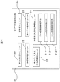
最初に、本実施例を実施するためのレーダ装置のブロック図を、図3、図4を用いて説明する。図3において、レーダ装置81は、信号生成機能、送信機能及び受信機能を有するアナログ回路1と、受信信号の処理機能を有する信号処理回路(デジタルプロセッサ)10を備えている。すなわち、アナログ回路1は、送信系に変調器2、発振器5、電力増幅器6、送信アンテナ3を備え、受信系に受信アンテナ4(a)、4(b)とミキサ回路7(a)、7(b)、電力増幅器8(a)、8(b)、A/Dコンバータ9(a)、9(b)を備えている。A/Dコンバータ9から出力された信号は、信号処理回路10で処理され、ターゲットまでの距離又は相対速度の少なくとも一方が求められる。信号処理回路10は、CPUやメモリ及びプログラムを保持するデータプロセッサにより構成され、高速フーリエ変換(FFT)処理部11、ピークサーチ処理部12、メモリ13、ターゲット位置算出部20、物体追跡処理部14を備えている。ターゲット位置算出部20は、時間差方式方位角算出ユニット21を備えている。また信号処理回路10には車速センサ30、ヨーレートセンサ31の出力も入力され、メモリ13に記録保持される。なお、信号処理回路10の上記各部は、各種プログラムに基づく演算処理をCPUで実行することにより得られる実現される機能である。信号処理回路10の具体的な構成は、上記各部の機能の一部を組み合わせて統合し、あるいは一部をさらに細分化して実現しても良いことは言うまでも無い。
First, a block diagram of a radar apparatus for carrying out this embodiment will be described with reference to FIGS. In FIG. 3, a
物体追跡処理部14で得られた情報は、シリアル通信手段などにより外部のACC(Adaptive Cruise Control)装置などに送られ、車両の走行制御を行う。
Information obtained by the object
図4に、ターゲット位置算出部20のより具体的な構成例を示す。ターゲット位置算出部20は、時間差方式方位角算出ユニット21の他に、モノパルス方式方位角算出ユニット22、相対速度算出ユニット23、距離算出ユニット24、時間差設定ユニット25、ターゲット数判定ユニット26を備えている。時間差方式方位角算出ユニット21は、ヌル点走査曲線算出部211、曲線比較部212、ヌル点走査曲線記憶部213を備えている。ヌル点走査曲線算出部211は後で説明するヌル点走査曲線(図11の曲線110、120)を算出する機能を有している。ヌル点走査曲線比較部212は2つのヌル点走査曲線の交点、すなわちターゲットの方位角を求める機能を有している。これらのヌル点に関する情報は、ヌル点走査曲線記憶部213に保持される。
FIG. 4 shows a more specific configuration example of the target
相対速度算出ユニット23および距離算出ユニット24では、例えば2周波CW方式の原理に基づいて、それぞれターゲットの相対速度と距離が算出される。時間差方式方位角算出ユニット21のヌル点走査曲線算出部211及び曲線比較部の機能については、後で説明する。
The relative
ターゲット数判定ユニット26は、反射信号の処理データからターゲット数を判定し、時間差方式方位角算出ユニット21とモノパルス方式方位角算出ユニット22のいずれで方位角算出の処理を行うべきかを判定処理する。
The target
方位角算出ユニット21、22では、それぞれ方位角を算出する。すなわち、時間差方式方位角算出ユニット21では、図1Aで説明した時間差方式に基づき、反射信号にドップラー周波数が同一となるターゲットが2つ存在する場合であっても、それぞれの方位角を算出する。一方、ターゲットが1つ存在する場合における方位角の算出は、モノパルス方式方位角算出ユニット22によって行う。
The
なお、ターゲット位置算出部20の構成は、上記各ユニットや各部の機能の一部を組み合わせて統合し、あるいは一部をさらに細分化して実現しても良いことは言うまでも無い。
Needless to say, the configuration of the target
次に、本発明の実施例の動作について、図5及び図7のフローチャートをベースにして、以下説明する。
アナログ回路1の発振器5は、変調器2からの変調信号に基づき、例えば図6Aで示した周波数パターンで発振する。これは2周波CW方式と呼ばれる周波数変調方式であるが、これに代えて例えばFMCW方式の変調方式等他の方式を採用しても良い。周波数変調された高周波信号は、電力増幅器6で増幅された後、送信アンテナ3から送信電波として検出領域へ向けて照射される。
Next, the operation of the embodiment of the present invention will be described below based on the flowcharts of FIGS.
The
送信アンテナ3から送信された電波は照射領域内の物体(ターゲット)で反射され、返ってきた電波信号は受信アンテナ4により受信される。この受信信号をミキサ回路7で発信信号とミキシングすることによってビート信号が生成され、このビート信号が電力増幅器8へ出力される。電力増幅器8で増幅され出力された信号は、A/Dコンバータ9によってディジタル信号に変換された後、信号処理回路10へ送られる。
The radio wave transmitted from the
この信号処理回路10では、図5に示されるフローチャートに従って受信信号に所定の演算が実施される。
In the
まず各変調区間において取得された単位のデータセットの各データに対してステップ41で高速フーリエ変換(FFT)による周波数解析を行って周波数スペクトルを得る。物体による反射波を受信した場合、信号対雑音電力比(S/N)の大きい周波数ピークとして、例えば図6Bに示した周波数スペクトル図のピーク50で示したように、観測される。このようにして観測されるピークを、次のステップ42のピークサーチで抽出する。ここで抽出された信号に対して、ステップ43においてターゲットの位置情報算出処理が施される。このステップ43の処理はターゲット位置算出部20により実行される。ターゲット位置算出部20の相対速度算出ユニット23および距離算出ユニット24では、例えば2周波CW方式の原理に基づいて、それぞれターゲットの相対速度と距離を算出する。
First, in
次に、図5中のステップ43で単位のデータセットを用いて2つのターゲット位置を計測し、その結果を利用して、夫々ステップ44で追尾処理を施す。ここでは過去の検知物体計測情報から予測される現在の計測情報に基づいて、実際に現在算出した情報を補正する。この補正手段は従来からレーダ技術の分野で用いられているカルマンフィルターやαβフィルタを利用する
なお、ここまではターゲットが2つ存在する場合を仮定していたが、ターゲットが1個の時にはXS(θ)は時刻Tiと時刻Ti+ΔTで全ての方位角について同じ値となる。なぜなら低利得方向がどこを向いていようともターゲット1個の信号だけを受信しており、干渉などは生じていないからである。この場合には、例えば通常のモノパルス方式に従ってターゲットの方位角度を求める。すなわち、図4のモノパルス方式方位角算出ユニット22により、図16、図17で説明したようにして、ターゲットの方位角度を求める。そして、ステップ44で追尾処理を施す。
Next, two target positions are measured using a unit data set in
図5に示した上記各処理は、レーダ装置81のアナログ回路1からのデータ入力に同期して繰り返し実行される。
Each process shown in FIG. 5 is repeatedly executed in synchronization with the data input from the
次に、ターゲット位置算出部20の動作を、図7に示すフローチャートに従って詳細に説明する。
Next, the operation of the target
既に述べたように、本発明では、微小な時間差ΔTの間に自車搭載のレーダの位置が移動することを利用して単位のデータセットを取得し、仮想的にアンテナ数をレーダの移動方向に沿って増やすことを特徴にしている。ただし、例えば交差点での一次停止のように自車搭載のレーダの位置は停止したままの状態でターゲットが自車に接近してくる場合も考えられる。この場合、自車搭載のレーダとターゲットとの相対的な位置関係の変化を検知るために、微小な時間差ΔTにおける自車とターゲット間の距離変化を利用する。 As described above, in the present invention, the data set of the unit is acquired by utilizing the position of the radar mounted on the own vehicle during the minute time difference ΔT, and the number of antennas is virtually set in the direction of movement of the radar. It is characterized by increasing along. However, for example, there may be a case where the target approaches the host vehicle while the position of the radar mounted on the host vehicle is stopped, such as a primary stop at an intersection. In this case, in order to detect a change in the relative positional relationship between the radar mounted on the vehicle and the target, a change in the distance between the vehicle and the target at a minute time difference ΔT is used.
図7において、ステップ71では、レーダとターゲットまでの距離が前回計測された値と一致しているか否かを判定する。変化している場合はターゲットとレーダの位置関係が変化しているため本発明の方位角計測方式を使用することができる。そこでステップ72へ進みヌル点走査曲線を求める。なお、ヌル点走査曲線については、後で図11を用いて詳細に説明する。ステップ73では前記ヌル点走査曲線と過去のどの時点に求め記憶したヌル点走査曲線、換言すると微小時間差ΔTをどの値にして1セットのヌル点走査曲線を比較するかを車速センサ、ヨーレートセンサの出力情報を基にして決定する。
In FIG. 7, in
ステップ74では、2つのヌル点走査曲線からターゲット数を求める。ターゲットが1個の時にはXS(θ)は時刻Tiと時刻Ti+ΔTで全ての方位角について同じ値となる。ターゲットが1個の場合には、通常のモノパルス方式に従ってターゲットの方位角度を求める(ステップ75、76)。
In
ステップ77では、2つのヌル点走査曲線(図11中の曲線110,120)の交点、すなわちターゲットの方位角θA,θBを求める。
In
最後にステップ78で現在求めたヌル点走査曲線とターゲット位置情報をメモリ等の記憶装置に登録する。
Finally, the null point scanning curve and the target position information currently obtained in
図8Aは、単位のデータセットすなわち2つの受信アンテナの受信信号に所定の演算を実施することで得られたアンテナ利得の低い方位角方向が、2つあるターゲットのうち1つの方向と一致している様子を示している。すなわち、図8Aは、前記(式1)中の位相回転角θが2個あるターゲットのうち片方と一致している場合を示している。この図ではターゲットAとターゲットBが存在し、位相回転角θはターゲットBの方位角θBと一致している。この時、ターゲットBからの反射信号は受信されず、ターゲットAからの反射信号だけを受信している状態となっている。つまり、ドップラーシフト周波数が同一のターゲットが2つある場合であっても、両者からの反射信号が合成されない状態を信号処理により生成している。 FIG. 8A shows that the azimuth direction having a low antenna gain obtained by performing a predetermined operation on the unit data set, that is, the reception signals of the two reception antennas coincides with one of the two targets. It shows how it is. That is, FIG. 8A shows a case where the phase rotation angle θ in (Equation 1) matches one of the two targets. In this figure, target A and target B exist, and the phase rotation angle θ matches the azimuth angle θ B of target B. At this time, the reflected signal from the target B is not received, and only the reflected signal from the target A is received. That is, even when there are two targets having the same Doppler shift frequency, a state in which the reflected signals from both are not synthesized is generated by signal processing.
一方、図8Bは、2つの受信アンテナの受信信号に所定の演算を実施することで生成されたアンテナ利得の低い方位角方向が、2つあるターゲットのうちいずれとも一致していない様子を示している。このように、低利得方向がターゲット方向と一致していない場合は、2つのターゲットからの反射信号は合成されている。この状態は2つの反射信号が干渉しているとも表現される。 On the other hand, FIG. 8B shows a state in which the azimuth direction having a low antenna gain generated by performing a predetermined calculation on the received signals of the two receiving antennas does not match any of the two targets. Yes. Thus, when the low gain direction does not coincide with the target direction, the reflected signals from the two targets are combined. This state is also expressed as two reflected signals interfering.
図8Bのようなときは2つの信号が合成されるため、個々の方位角を計測することはできない。図8Aの状態が起きているときは、その位相回転角θがわかれば、ターゲットの方位角位置がわかることになる。しかし、実際に計算する際には、低利得方向を全方位角方向スキャンしており、どの方向に向けたときに、図8Aの状態になっているかはわからない。 In the case of FIG. 8B, since two signals are combined, individual azimuth angles cannot be measured. When the state of FIG. 8A occurs, the azimuth angle position of the target can be known if the phase rotation angle θ is known. However, in the actual calculation, the low gain direction is scanned in all azimuth directions, and it is not known in which direction the state is as shown in FIG. 8A.
そこで、以下の方法により、ターゲットの方位角を決定する。
まず、(式1)で表されるXS(θ)の、位相回転角θを検知角度範囲内で例えば0.1度刻みで変化させながら計算する。そしてXS(θ)の絶対値を位相回転角θの関数として描くと例えば図11中のヌル点走査曲線110のようになる。本発明では、このようにして生成される曲線をヌル点走査曲線と定義する。この時の時刻をTiとする。続いて時刻が微少時間ΔTだけ過ぎたTi+ΔTでも同じ計算処理を行い、同様の曲線を描くと例えば図11中のヌル点走査曲線120のようになる。ここで微少時間ΔTだけ離れた時刻とは例えば数十ミリ秒程度の固定値でも良いし、あるいは数十ミリ秒程度の初期値を基準として車速センサ30やヨーレートセンサ31から得られる自車両の走行状況の情報に応じて変化させても構わない。
Therefore, the azimuth angle of the target is determined by the following method.
First, calculation is performed while changing the phase rotation angle θ of XS (θ) represented by (Expression 1) within the detection angle range, for example, in increments of 0.1 degrees. When the absolute value of XS (θ) is drawn as a function of the phase rotation angle θ, for example, a null
以下では、上記2本のヌル点走査曲線110、120の交点の位相回転角θが、ターゲットの方位角位置θA、θBとなっていることを説明する。 Hereinafter, it will be described that the phase rotation angle θ at the intersection of the two null point scanning curves 110 and 120 is the azimuth positions θ A and θ B of the target.
図8Aの状態は、ターゲットAからの反射信号のみが受信されている状態である。この後、レーダが微少に動いただけではその信号強度はほとんど変化しない。つまりXS(θA)の絶対値は時刻Ti, 時刻Ti+ΔTでほぼ同じ値となる。これは図9A、図9Bを用いて以下のように解釈することもできる。時刻Tiにおいてヌル点がターゲットBを向いていた場合、ターゲットAからの反射波の強度を図9A中の太線100の長さL1で表すとする。次に時刻Ti+ΔTの時も同様にターゲットAからの反射波の強度を図9B中の太線101で表す。この時、Ti+ΔT−Tiが小さければ太線100、太線101の長さL2は等しいと考えることができる。
The state of FIG. 8A is a state in which only the reflected signal from the target A is received. Thereafter, the signal intensity hardly changes when the radar is moved only slightly. That is, the absolute value of XS (θ A ) is substantially the same at time Ti and time Ti + ΔT. This can also be interpreted as follows using FIGS. 9A and 9B. When the null point faces the target B at time Ti, the intensity of the reflected wave from the target A is represented by the length L1 of the
同様に、低利得方向がターゲットAを向いた時はターゲットBからの反射信号のみを受信している状態であるため、時刻Tiと時刻Ti+ΔTでXS(θB)はほぼ等しくなる。 Similarly, when the low gain direction is directed to the target A, since only the reflected signal from the target B is received, XS (θ B ) is substantially equal at time Ti and time Ti + ΔT.
一方、位相回転角θがターゲット位置とは異なる方位角である場合、2つのターゲットからの反射信号は干渉し合うため、時刻の経過に伴いレーダの位置が移動してターゲットとの位置関係が変化すると、両者の反射信号の合成のされ方が異なる。この場合、一般に合成信号の強度は大きく変動し、XS(θ)は時刻TiとTi+ΔTで異なる値となる(L1≠L2)。以上の振る舞いを表に纏めたのが図10である。 On the other hand, when the phase rotation angle θ is an azimuth angle different from the target position, the reflected signals from the two targets interfere with each other, so that the position of the radar moves and the positional relationship with the target changes over time. Then, the way in which the reflected signals of both are combined is different. In this case, in general, the intensity of the combined signal varies greatly, and XS (θ) has different values at times Ti and Ti + ΔT (L1 ≠ L2). FIG. 10 summarizes the above behavior in a table.
すなわち、θ=θA、θBの時(低利得方向がターゲットを向いている時)、片方の反射信号のみ受信しており、かつその強度は同一である。一方、この条件以外のとき、両ターゲットからの反射信号が干渉している。そして、一般に、反射信号の強度は時刻変動する。 That is, when θ = θA, θB (when the low gain direction is directed to the target), only one reflected signal is received and the intensity is the same. On the other hand, when the condition is not met, the reflected signals from both targets interfere. In general, the intensity of the reflected signal varies with time.
以上のことから、2つのヌル点走査曲線110、120の交点の位置を求めれば、ターゲットAとターゲットBの方位角位置θA,θBが求まることがわかる。 From the above, it can be seen that the azimuth positions θ A and θ B of the target A and the target B can be obtained by obtaining the position of the intersection of the two null point scanning curves 110 and 120.
なお、僅かに異なる時間差ΔTが長すぎると、太線100、太線101の長さが等しい状態を検知し難くなり干渉状態にある2つの反射信号を識別し難くなる。逆に、時間差ΔTが短すぎると、太線100、太線101の長さが等しい状態のデータを不必要に多く取得することになる。換言すると、本発明において、僅かに異なる時間差ΔTは、低利得方向が1つのターゲットを向いた時に他方のターゲットからの反射信号XS(θB)がほぼ等しい状態として検知される適度の数のデータを取得するのに適した時間間隔として、適宜設定すればよいことが分かる。
If the slightly different time difference ΔT is too long, it is difficult to detect a state where the lengths of the
以上に説明した処理に従えば、受信アンテナが2チャンネルしかない場合であっても、ドップラー周波数が一致する2つのターゲットの方位角を個別に計測することが可能となるため、図12の様なシーンでもレーダ出力結果は2つのポイント98に示されるように、実際の2つのターゲット位置と一致する。したがって、一般的なモノパルス方式を利用する場合と比べて誤検知出力を低減することが可能となる。
According to the processing described above, even when the receiving antenna has only two channels, the azimuth angles of two targets having the same Doppler frequency can be individually measured. Even in the scene, the radar output result coincides with the actual two target positions as indicated by two
図13A、図13Bは、本発明の実施例に基づくレーダ装置と従来のモノパルス方式に基づくレーダ装置を夫々車に搭載して、ターゲット位置検出処理を行った実験結果の一例を示すものであり、図13Aが本発明の実施例、図13Bが従来のモノパルス方式による結果を示す。いずれの場合も、前提として、レーダ装置は受信アンテナが2チャンネルから構成されており、自車の前方の検出領域内に2つのターゲットが位置し(図12の様なシーン)、かつ、自車の速度が前方を走行する2つのターゲットの速度よりも大きいものとする。本発明の実施例によれば、(A)に示すとおり、2つのターゲットの角度が最小分離可能角度と等しくなる距離よりも近距離側において2つのターゲットを明確に識別し区別できている。一方、従来のモノパルス方式では、(B)に示すとおり、あたかも1つのターゲットがふらついているかのように検出される。これは、2つのターゲットからの反射信号が干渉しているためである。 FIG. 13A and FIG. 13B show an example of an experimental result in which a radar device based on an embodiment of the present invention and a radar device based on a conventional monopulse system are respectively mounted on a vehicle and target position detection processing is performed. FIG. 13A shows an example of the present invention, and FIG. 13B shows a result of a conventional monopulse system. In any case, as a premise, the radar apparatus has two receiving antennas, two targets are located in the detection area in front of the own vehicle (scene as shown in FIG. 12), and the own vehicle Is greater than the speeds of the two targets traveling ahead. According to the embodiment of the present invention, as shown in (A), it is possible to clearly identify and distinguish the two targets closer to the distance side than the distance at which the angles of the two targets are equal to the minimum separable angle. On the other hand, in the conventional monopulse system, as shown in (B), detection is performed as if one target is flickering. This is because the reflected signals from the two targets interfere with each other.
このように、本発明によれば、ドップラーシフト周波数が同一となる2つのターゲットが存在する場合でも、簡単な構成で、例えば、モノパルス方式を採用したレーダ装置のハード構成に時間差方式方位角算出の機能を付加することで、2つのターゲットそれぞれの方位角を計測することが可能な信号処理手段を有したレーダ装置を提供することができる。 As described above, according to the present invention, even when there are two targets having the same Doppler shift frequency, the time difference method azimuth calculation can be performed with a simple configuration, for example, in the hardware configuration of the radar apparatus employing the monopulse method. By adding a function, it is possible to provide a radar apparatus having a signal processing means capable of measuring the azimuth angles of two targets.
なお、レーダ装置が静止状態にある場合でも、このレーダ装置に対して相対的に移動するターゲットに対しては、時間差方式方位角算出ユニット21等を備えた信号処理回路10において、上記信号処理を用いることによりこのターゲットの方位角を計測することができることは言うまでも無い。すなわち、電波を放射しその反射波を処理して物体を検出するレーダ装置において、レーダ装置に装着されたアンテナにより現在取得された計測データと、ターゲットとアンテナとの相対的な位置関係が現在の時刻とは微小時間ΔTだけ異なる時刻に取得された計測データとを単位のデータセットとして使用して時間差方式で方位角を算出することで、2つのターゲットそれぞれの方位角を計測することができる。
Even when the radar apparatus is in a stationary state, the
以上述べた実施例では、本発明のレーダ装置を車両に搭載して用いることを想定したが、用途は自動車用に限るものではない。たとえば、航空機や船舶に設置して障害物を監視し、走行制御や警告を行う装置として使用することもできる。 In the embodiments described above, it is assumed that the radar apparatus of the present invention is mounted on a vehicle and used, but the application is not limited to automobiles. For example, it can be used as a device that is installed in an aircraft or a ship, monitors obstacles, and performs running control or warning.
1…レーダ装置の高周波回路、
2…変調器、
3…送信アンテナ、
4(a),4(b)…受信アンテナ、
5…発信器、
6…電力増幅器、
7a,7b…ミキサ回路、
8a,8b…電力増幅器、
9a,9b…A/Dコンバータ、
10…信号処理部、
11…高速フーリエ変換(FFT)処理部、
12…ピークサーチ処理部、
13…メモリ、
14…物体追跡処理部、
20…ターゲット位置算出部、
21…時間差方式方位角算出ユニット、
211…ヌル点走査曲線算出部、
212…ヌル点走査曲線比較部、
213…ヌル点走査曲線記憶部、
22…モノパルス方式方位角算出ユニット、
23…相対速度算出ユニット、
24…距離算出ユニット、
25…時間差設定ユニット、
26…ターゲット数判定ユニット、
50…周波数スペクトルのピーク、
60…2つの受信アンテナにより取得された2つの受信信号に所定の演算を実施することで構成されたビームパターン、
80…レーダを搭載した車両、
81…レーダ装置、
90、92,94…前方を走行する車両、
96…モノパルス方式の原理で計測された、誤検知出力位置、
98…本発明のレーダ装置で計測されたターゲットの出力位置、
110…(式1)で計算されるXS(θ)の時刻Tiにおける絶対値、
120…(式1)で計算されるXS(θ)の時刻Ti+ΔTにおける絶対値、
301…スキャン方式を採用しているレーダ装置のアンテナ、
302…スキャン方式を採用しているレーダ装置のアンテナから放射されるビームパターン。
1 ... High frequency circuit of radar equipment,
2 ... modulator,
3 ... Transmitting antenna,
4 (a), 4 (b) ... receiving antenna,
5 ... Transmitter,
6 ... Power amplifier,
7a, 7b ... mixer circuit,
8a, 8b ... power amplifier,
9a, 9b ... A / D converter,
10: Signal processing unit,
11: Fast Fourier transform (FFT) processing unit,
12 ... Peak search processing unit,
13 ... Memory,
14 ... Object tracking processing unit,
20 ... Target position calculation unit,
21: Time difference azimuth calculation unit,
211 ... Null point scanning curve calculation unit,
212 ... Null point scanning curve comparison unit,
213 ... Null point scanning curve storage unit,
22 ... Monopulse azimuth calculation unit,
23 ... Relative speed calculation unit,
24 ... Distance calculation unit,
25: Time difference setting unit,
26 ... target number determination unit,
50 ... peak of frequency spectrum,
60 ... A beam pattern formed by performing a predetermined calculation on two received signals acquired by two receiving antennas,
80 ... Vehicle equipped with radar,
81. Radar device,
90, 92, 94 ... vehicles traveling in front,
96 ... false detection output position measured by the principle of the monopulse method,
98 ... The output position of the target measured by the radar apparatus of the present invention,
110... Absolute value at time Ti of XS (θ) calculated by (Expression 1)
120... Absolute value at time Ti + ΔT of XS (θ) calculated by (Equation 1)
301 ... Radar apparatus antenna adopting a scanning method,
302: A beam pattern radiated from an antenna of a radar apparatus employing a scanning method.
Claims (12)
前記信号処理回路は、前記受信信号として、前記1対の受信アンテナにより取得された第1のデータと前記第1のデータとは異なる時刻に取得された第2のデータとを単位のデータセットとすることで仮想的にアンテナ数を2倍とする機能と、
前記単位のデータセットから前記受信信号の強度変化を求め、複数の前記ターゲットの位置を計測する機能とを備えたレーダ装置であって、
前記1対の受信アンテナにより得られた2つの受信信号のうち、片方の位相を回転させながら両者の線型和を計算することによりアンテナ利得の小さい方位角方向を信号処理的に生成する機能と、
前記アンテナ利得の小さい方位角方向をスキャンして、現在の時刻Tiで計測された受信信号の強度と前記時刻Tiから時間ΔTだけ異なる時刻に取得されたデータから計算された受信信号の強度が同一となる前記位相の回転角をターゲットの存在角度であると判断して出力する機能とを備えており、
前記ターゲットと前記レーダ装置との位置関係は時間の経過と共に変化するものである
ことを特徴とするレーダ装置。 One transmission antenna that transmits a transmission radio wave to the detection region, a pair of reception antennas that are arranged at left and right positions and that receive a reflected wave from the target, and a function that processes a reception signal received by the reception antenna Comprising a signal processing circuit,
The signal processing circuit includes, as the received signal, a first data acquired by the pair of receiving antennas and a second data acquired at a time different from the first data as a unit data set. To virtually double the number of antennas,
Seeking changes in the intensity of the received signal from the data set of the unit, a radar apparatus example Bei a function of measuring the positions of a plurality of said target,
A function of generating an azimuth direction with a small antenna gain in a signal processing manner by calculating a linear sum of the two received signals obtained by the pair of receiving antennas while rotating one of the phases;
Scanning the azimuth direction with a small antenna gain, the intensity of the received signal measured at the current time Ti is the same as the intensity of the received signal calculated from data acquired at a time different from the time Ti by a time ΔT. And the function of determining and outputting the rotation angle of the phase to be the presence angle of the target,
The radar apparatus according to claim 1, wherein a positional relationship between the target and the radar apparatus changes with time .
前記複数のターゲットの計測される位置は前記各ターゲットの方位角である
ことを特徴とするレーダ装置。 In claim 1,
The radar apparatus according to claim 1, wherein the measured positions of the plurality of targets are azimuth angles of the targets.
前記信号処理回路は、
前記1対の受信アンテナにより取得された信号をそれぞれフーリエ変換し、前記ターゲットからの反射信号を検出する機能と、
前記検出された複素数からなる2つの反射信号をS 1 , S 2 としたとき、該複素数値S 1 の位相をθだけ回転させながら、次式(1)に従って線型和XS(θ)を計算する機能と、
ことを特徴とするレーダ装置。 In claim 1,
The signal processing circuit includes:
A function of Fourier-transforming each of the signals acquired by the pair of receiving antennas to detect a reflected signal from the target;
When the two reflected signals composed of the detected complex numbers are S 1 and S 2 , the linear sum XS (θ) is calculated according to the following equation (1) while rotating the phase of the complex value S 1 by θ. Function and
前記信号処理回路は、
前記式(1)中の位相回転角θが、2個ある前記ターゲットのうち片方と一致している状態を現出することにより、ドップラーシフト周波数が同一の前記2つのターゲットが存在する場合において、前記2つのターゲットからの前記反射信号が合成されない状態を信号処理により生成する機能を有する
ことを特徴とするレーダ装置。 In claim 3 ,
The signal processing circuit includes:
In the case where the two targets having the same Doppler shift frequency are present by revealing a state in which the phase rotation angle θ in the formula (1) matches one of the two targets, A radar apparatus having a function of generating a state in which the reflected signals from the two targets are not combined by signal processing .
前記信号処理回路は、
前記複素数値S 1 の位相をθだけ回転させる
ことを特徴とするレーダ装置。 In claim 3,
The signal processing circuit includes:
Radar apparatus according to claim <br/> rotating the complex values S 1 of phase by theta.
前記信号処理回路は、
前記(式1)中の位相回転角θが、2個ある前記ターゲットのうち片方と一致している状態を現出することにより、ドップラーシフト周波数が同一の前記2つのターゲットが存在する場合において、前記2つのターゲットからの前記反射信号が合成されない状態を信号処理により生成する
ことを特徴とするレーダ装置。 In claim 5,
The signal processing circuit includes:
In the case where the two targets having the same Doppler shift frequency exist by revealing a state in which the phase rotation angle θ in (Expression 1) matches one of the two targets, A radar apparatus, wherein a state in which the reflected signals from the two targets are not combined is generated by signal processing.
前記単位のデータセットに使用する前記異なる時刻の時間差ΔTは、当該レーダ装置の移動速度に応じて変更される
ことを特徴とするレーダ装置。 In claim 1 ,
The radar apparatus according to claim 1, wherein the time difference [Delta] T of the different times used for the unit data set is changed according to a moving speed of the radar apparatus.
前記レーダ装置は、時刻の経過とともに移動する
ことを特徴とするレーダ装置。 In claim 1 ,
The radar apparatus, wherein the radar apparatus moves with time .
前記レーダ装置は、車両に搭載されており、
前記単位のデータセットに使用する前記異なる時刻の時間間隔ΔTは、当該レーダ装置を搭載した車両の走行速度及び該車両のヨーレートに応じて変更される
ことを特徴とするレーダ装置。 In claim 1 ,
The radar device is mounted on a vehicle,
The radar apparatus according to claim 1, wherein the time interval ΔT of the different times used for the unit data set is changed according to a traveling speed of a vehicle on which the radar apparatus is mounted and a yaw rate of the vehicle .
前記レーダ装置が静止位置にあり、
前記信号処理回路は、
前記単位のデータセットに含まれる現在取得された計測データと、前記ターゲットと前記レーダ装置のアンテナとの相対的な位置関係が現在の時刻における位置関係とは異なる、前記時間ΔTだけ過去に取得された計測データとを使用して、前記ターゲットの方位角を計測する機能を有する
ことを特徴とするレーダ装置。 In claim 1,
The radar device is in a stationary position;
The signal processing circuit includes:
The measurement data included in the unit data set and the relative positional relationship between the target and the antenna of the radar apparatus are different from the positional relationship at the current time, and are acquired in the past for the time ΔT. A radar apparatus having a function of measuring the azimuth angle of the target using the measured data .
信号生成機能、送信機能及び受信機能を有するアナログ回路と、受信信号の処理機能を有する信号処理回路とを備えて成り、
前記アナログ回路は、送信電波を検出領域に送信する1個の送信アンテナと、左右の位置に配置された1対の受信アンテナとを備えて成り、
前記信号処理回路は、受信された前記送信電波の反射波を受信信号として処理しターゲットを追跡する機能を有している
ことを特徴とするレーダ装置。 The radar apparatus according to claim 1 , wherein
An analog circuit having a signal generation function, a transmission function and a reception function, and a signal processing circuit having a reception signal processing function,
The analog circuit includes one transmission antenna that transmits a transmission radio wave to a detection region, and a pair of reception antennas that are arranged at left and right positions.
The radar apparatus according to claim 1, wherein the signal processing circuit has a function of processing a reflected wave of the received transmission radio wave as a received signal and tracking a target .
前記1個の送信アンテナから送信電波を検出領域に送信し、
前記左右の位置に配置された前記1対の受信アンテナで前記送信電波の反射波を受信し、
前記1対の受信アンテナにより取得された第1のデータと、前記第1のデータとは異なる時刻に取得された第2のデータとを受信信号の単位のデータセットとし、
前記単位のデータセットから前記受信信号の強度変化を求め複数の前記ターゲットの方位角位置を計測するものにおいて、
前記ターゲットと前記レーダ装置との位置関係は時間の経過と共に変化するものであり、
前記1対の受信アンテナにより得られた2つの受信信号のうち、片方の位相を回転させながら両者の線型和を計算することによりアンテナ利得の小さい方位角方向を信号処理的に生成し、
前記アンテナ利得の小さい方位角方向をスキャンして、現在の時刻Tiで計測された受信信号の強度と前記時刻Tiから時間ΔTだけ異なる時刻に取得されたデータから計算された受信信号の強度が同一となる前記位相の回転角をターゲットの存在角度であると判断して出力する
ことを特徴とするターゲットの方位角計測方法。 Azimuth angle measurement of a target in a radar apparatus comprising one transmission antenna, a pair of reception antennas arranged at left and right positions, and a signal processing circuit having a function of processing a reception signal received by the reception antenna A method,
Transmitting a transmission radio wave from the one transmission antenna to a detection region;
The reflected wave of the transmission radio wave is received by the pair of reception antennas arranged at the left and right positions,
The first data acquired by the pair of receiving antennas and the second data acquired at a time different from the first data are set as a unit data set of received signals,
In what determines the intensity change of the received signal from the data set of the unit and measures the azimuth angle position of the plurality of targets,
The positional relationship between the target and the radar device changes with the passage of time,
Of the two received signals obtained by the pair of receiving antennas, by calculating the linear sum of both while rotating the phase of one of them, an azimuth direction with a small antenna gain is generated in a signal processing manner,
Scanning the azimuth direction with a small antenna gain, the intensity of the received signal measured at the current time Ti is the same as the intensity of the received signal calculated from data acquired at a time different from the time Ti by a time ΔT. It is determined that the rotation angle of the above phase is the target presence angle and is output.
A method for measuring an azimuth angle of a target.
Priority Applications (4)
| Application Number | Priority Date | Filing Date | Title |
|---|---|---|---|
| JP2007323068A JP5091651B2 (en) | 2007-12-14 | 2007-12-14 | Radar apparatus and target azimuth measurement method |
| DE602008005998T DE602008005998D1 (en) | 2007-12-14 | 2008-12-10 | Radar apparatus and method for measuring the azimuth angle of the target |
| EP08171208A EP2071357B1 (en) | 2007-12-14 | 2008-12-10 | Radar apparatus and method of measuring azimuth angle of target |
| US12/314,578 US7760134B2 (en) | 2007-12-14 | 2008-12-12 | Radar apparatus and method of measuring azimuth angle of target |
Applications Claiming Priority (1)
| Application Number | Priority Date | Filing Date | Title |
|---|---|---|---|
| JP2007323068A JP5091651B2 (en) | 2007-12-14 | 2007-12-14 | Radar apparatus and target azimuth measurement method |
Publications (3)
| Publication Number | Publication Date |
|---|---|
| JP2009145206A JP2009145206A (en) | 2009-07-02 |
| JP2009145206A5 JP2009145206A5 (en) | 2011-01-20 |
| JP5091651B2 true JP5091651B2 (en) | 2012-12-05 |
Family
ID=40427887
Family Applications (1)
| Application Number | Title | Priority Date | Filing Date |
|---|---|---|---|
| JP2007323068A Active JP5091651B2 (en) | 2007-12-14 | 2007-12-14 | Radar apparatus and target azimuth measurement method |
Country Status (4)
| Country | Link |
|---|---|
| US (1) | US7760134B2 (en) |
| EP (1) | EP2071357B1 (en) |
| JP (1) | JP5091651B2 (en) |
| DE (1) | DE602008005998D1 (en) |
Cited By (1)
| Publication number | Priority date | Publication date | Assignee | Title |
|---|---|---|---|---|
| US11474535B2 (en) | 2018-10-08 | 2022-10-18 | Hl Klemove Corp. | Method of processing data, apparatus for processing data, and system for controlling vehicle |
Families Citing this family (21)
| Publication number | Priority date | Publication date | Assignee | Title |
|---|---|---|---|---|
| JP5501578B2 (en) * | 2008-06-30 | 2014-05-21 | 三菱電機株式会社 | Radar equipment |
| JP5093298B2 (en) * | 2010-06-04 | 2012-12-12 | 株式会社デンソー | Direction detection device |
| JP5653726B2 (en) * | 2010-11-12 | 2015-01-14 | 株式会社デンソー | Radar equipment |
| US8854052B2 (en) * | 2010-11-22 | 2014-10-07 | General Electric Company | Sensor assembly and method of measuring the proximity of a machine component to a sensor |
| US20120126829A1 (en) * | 2010-11-22 | 2012-05-24 | Boris Leonid Sheikman | Methods and systems for monitoring components using a microwave emitter |
| KR101207890B1 (en) | 2011-02-01 | 2012-12-04 | 재단법인대구경북과학기술원 | Angle Detection Apparatus Of Multi Moving Tarket In Automotive Pulse Radar And Method Thereof |
| TWI448715B (en) | 2012-07-30 | 2014-08-11 | Univ Nat Chiao Tung | Motion parameter estimating method, angle estimating method and determination method |
| TWI470257B (en) | 2013-10-07 | 2015-01-21 | Univ Nat Chiao Tung | Method and electronic device for angle estimation verification |
| JP6365251B2 (en) * | 2014-02-28 | 2018-08-01 | パナソニック株式会社 | Radar equipment |
| KR102435550B1 (en) * | 2015-06-09 | 2022-08-24 | 주식회사 에이치엘클레무브 | Apparatur for processing signal of radar and method for processing signal thereof |
| RU2631118C1 (en) * | 2016-10-24 | 2017-09-19 | Акционерное общество "Государственный Рязанский приборный завод" | Method of determining azimuth of object with help of interpolated direction-finding characteristics |
| US11922564B2 (en) | 2017-06-05 | 2024-03-05 | Umajin Inc. | Generative content system that supports location-based services and methods therefor |
| US11954486B2 (en) | 2017-06-05 | 2024-04-09 | Umajin Inc. | Location tracking system and methods |
| US12020354B2 (en) | 2017-06-05 | 2024-06-25 | Umajin Inc. | Hub and spoke classification system |
| US11726822B2 (en) | 2017-06-05 | 2023-08-15 | Umajin Inc. | Systems and methods for providing digital twin-enabled applications |
| WO2018226621A1 (en) | 2017-06-05 | 2018-12-13 | Umajin Inc. | Methods and systems for an application system |
| US12001917B2 (en) | 2017-06-05 | 2024-06-04 | Umajin Inc. | Hub-and-spoke classification system and methods |
| US11092686B2 (en) * | 2018-09-19 | 2021-08-17 | Steradian Semiconductors Private Limited | Method, apparatus and device for doppler compensation in a time switched MIMO radar system |
| WO2020157924A1 (en) * | 2019-01-31 | 2020-08-06 | 三菱電機株式会社 | Angle measuring device, angle measuring method, and vehicle-mounted device |
| CN110940957B (en) * | 2019-10-28 | 2022-03-22 | 惠州市德赛西威汽车电子股份有限公司 | Modular millimeter wave radar |
| CN113030933B (en) * | 2021-02-22 | 2024-06-04 | 上海蛮酷科技有限公司 | Target azimuth calculation method for radar, radar apparatus, and readable storage medium |
Family Cites Families (15)
| Publication number | Priority date | Publication date | Assignee | Title |
|---|---|---|---|---|
| US2991463A (en) * | 1956-05-28 | 1961-07-04 | Thompson Ramo Wooldridge Inc | Collision indication system |
| JP3016047B2 (en) | 1991-12-27 | 2000-03-06 | 本田技研工業株式会社 | Position Estimation Method of Contrast Obstacle in Vehicle |
| JP3491418B2 (en) * | 1995-12-01 | 2004-01-26 | 株式会社デンソー | FMCW radar equipment |
| JPH11125672A (en) * | 1997-10-24 | 1999-05-11 | Mitsubishi Electric Corp | Fm-cw radar |
| JPH11133143A (en) * | 1997-10-31 | 1999-05-21 | Toyota Motor Corp | Radar device |
| DE19912370A1 (en) * | 1998-05-02 | 1999-12-16 | Daimlerchrysler Aerospace Ag | Method of radar signal processing for radar system, especially for motor vehicles |
| JP3829659B2 (en) * | 2001-07-02 | 2006-10-04 | 三菱電機株式会社 | Radar equipment |
| JP4079739B2 (en) | 2002-10-08 | 2008-04-23 | 富士通テン株式会社 | Automotive radar equipment |
| US7224717B1 (en) * | 2002-11-15 | 2007-05-29 | Lockheed Martin Corporation | System and method for cross correlation receiver |
| DE10258367A1 (en) * | 2002-12-12 | 2004-07-08 | Daimlerchrysler Ag | Multi-objective method and multi-objective sensor device for the distance and angle localization of target objects in the vicinity |
| JP2004239744A (en) | 2003-02-06 | 2004-08-26 | Hitachi Ltd | Radar equipment |
| JP4093109B2 (en) * | 2003-05-15 | 2008-06-04 | 株式会社デンソー | Radar equipment for vehicles |
| WO2005101051A2 (en) * | 2004-04-12 | 2005-10-27 | Ghz Tr Corporation | Method and apparatus for automotive radar sensor |
| JP2006047114A (en) * | 2004-08-04 | 2006-02-16 | Fujitsu Ten Ltd | Radar system |
| JP3954053B2 (en) | 2004-09-03 | 2007-08-08 | 三菱電機株式会社 | Vehicle periphery monitoring device |
-
2007
- 2007-12-14 JP JP2007323068A patent/JP5091651B2/en active Active
-
2008
- 2008-12-10 EP EP08171208A patent/EP2071357B1/en not_active Not-in-force
- 2008-12-10 DE DE602008005998T patent/DE602008005998D1/en active Active
- 2008-12-12 US US12/314,578 patent/US7760134B2/en active Active
Cited By (1)
| Publication number | Priority date | Publication date | Assignee | Title |
|---|---|---|---|---|
| US11474535B2 (en) | 2018-10-08 | 2022-10-18 | Hl Klemove Corp. | Method of processing data, apparatus for processing data, and system for controlling vehicle |
Also Published As
| Publication number | Publication date |
|---|---|
| US7760134B2 (en) | 2010-07-20 |
| EP2071357B1 (en) | 2011-04-06 |
| JP2009145206A (en) | 2009-07-02 |
| EP2071357A1 (en) | 2009-06-17 |
| US20090153395A1 (en) | 2009-06-18 |
| DE602008005998D1 (en) | 2011-05-19 |
Similar Documents
| Publication | Publication Date | Title |
|---|---|---|
| JP5091651B2 (en) | Radar apparatus and target azimuth measurement method | |
| US9983301B2 (en) | Automated vehicle radar system to determine yaw-rate of a target vehicle | |
| US9310470B2 (en) | Radar apparatus and signal processing method | |
| EP1467223B1 (en) | Radar device | |
| US10234541B2 (en) | FMCW radar device | |
| JP4593468B2 (en) | Radar equipment | |
| JP4829517B2 (en) | Radar signal processing device | |
| JP4754856B2 (en) | Automotive radar equipment | |
| JP2009041981A (en) | Object detection system and vehicle equipped with object detection system | |
| JP5122536B2 (en) | Radar equipment | |
| JP6746017B2 (en) | Electronic device, electronic device control method, and electronic device control program | |
| US9348023B2 (en) | Radar apparatus and signal processing method | |
| JP2008082974A (en) | Object detector, object detecting method, and program executed by computer | |
| JP3664671B2 (en) | Millimeter wave radar equipment | |
| JP5059717B2 (en) | Monopulse radar device | |
| US6943727B2 (en) | Length measurement with radar | |
| WO2018181743A1 (en) | Vehicle-mounted radar device | |
| JP4779704B2 (en) | Target detection apparatus and target detection method | |
| JP2009014405A (en) | In-vehicle radar apparatus | |
| JP3518363B2 (en) | FMCW radar device, recording medium, and vehicle control device | |
| JP2014006122A (en) | Object detector | |
| JP2021073452A (en) | Electronic device, electronic device control method, and electronic device control program | |
| JP2014145731A (en) | Target detection apparatus and target detection method | |
| JP2010237087A (en) | Radar apparatus and method for measuring radio wave arrival direction using the same | |
| JP4863679B2 (en) | Position measuring device |
Legal Events
| Date | Code | Title | Description |
|---|---|---|---|
| A711 | Notification of change in applicant |
Free format text: JAPANESE INTERMEDIATE CODE: A712 Effective date: 20100108 |
|
| A521 | Request for written amendment filed |
Free format text: JAPANESE INTERMEDIATE CODE: A523 Effective date: 20101125 |
|
| A621 | Written request for application examination |
Free format text: JAPANESE INTERMEDIATE CODE: A621 Effective date: 20101125 |
|
| A977 | Report on retrieval |
Free format text: JAPANESE INTERMEDIATE CODE: A971007 Effective date: 20120704 |
|
| TRDD | Decision of grant or rejection written | ||
| A01 | Written decision to grant a patent or to grant a registration (utility model) |
Free format text: JAPANESE INTERMEDIATE CODE: A01 Effective date: 20120828 |
|
| A01 | Written decision to grant a patent or to grant a registration (utility model) |
Free format text: JAPANESE INTERMEDIATE CODE: A01 |
|
| A61 | First payment of annual fees (during grant procedure) |
Free format text: JAPANESE INTERMEDIATE CODE: A61 Effective date: 20120914 |
|
| FPAY | Renewal fee payment (event date is renewal date of database) |
Free format text: PAYMENT UNTIL: 20150921 Year of fee payment: 3 |
|
| R150 | Certificate of patent or registration of utility model |
Ref document number: 5091651 Country of ref document: JP Free format text: JAPANESE INTERMEDIATE CODE: R150 Free format text: JAPANESE INTERMEDIATE CODE: R150 |
|
| S533 | Written request for registration of change of name |
Free format text: JAPANESE INTERMEDIATE CODE: R313533 |
|
| R350 | Written notification of registration of transfer |
Free format text: JAPANESE INTERMEDIATE CODE: R350 |