JP4863679B2 - Position measuring device - Google Patents
Position measuring device Download PDFInfo
- Publication number
- JP4863679B2 JP4863679B2 JP2005286756A JP2005286756A JP4863679B2 JP 4863679 B2 JP4863679 B2 JP 4863679B2 JP 2005286756 A JP2005286756 A JP 2005286756A JP 2005286756 A JP2005286756 A JP 2005286756A JP 4863679 B2 JP4863679 B2 JP 4863679B2
- Authority
- JP
- Japan
- Prior art keywords
- target
- position data
- wide
- measured
- unit
- Prior art date
- Legal status (The legal status is an assumption and is not a legal conclusion. Google has not performed a legal analysis and makes no representation as to the accuracy of the status listed.)
- Expired - Fee Related
Links
Images


Description
本発明は、位置測定装置に係わり、特に複数の広角レーダ装置を用いて目標物の位置を測定する位置測定装置に関する。 The present invention relates to a position measurement device , and more particularly to a position measurement device that measures the position of a target using a plurality of wide-angle radar devices.
広角レーダ装置を用いて、周辺の車両や障害物の位置を検出し、その位置情報に基づいて警報をユーザに提示するシステムがある。広角レーダ装置は、少数の送受信アンテナ素子を備え、各送信アンテナ素子から幅広のビームを繰り返し放射し、ターゲット(目標物)に反射した反射ビームを対応する受信アンテナ素子で受信する。しかる後、レーダ信号解析部において受信波と送信波の時間差より距離を計測し、周波数の変化分より速度を算出する。また、それぞれの送受信アンテナにおける反射強度を比重計算することで、ターゲットの方向を算出する。 There is a system that uses a wide-angle radar device to detect positions of surrounding vehicles and obstacles and presents an alarm to a user based on the position information. The wide-angle radar device includes a small number of transmission / reception antenna elements, repeatedly radiates a wide beam from each transmission antenna element, and receives the reflected beam reflected on the target (target) by the corresponding reception antenna element. Thereafter, the radar signal analyzer measures the distance from the time difference between the received wave and the transmitted wave, and calculates the speed from the change in frequency. Further, the direction of the target is calculated by calculating the specific gravity of the reflection intensity at each transmitting / receiving antenna.
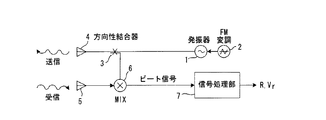
図6は広角レーダ装置としてのFM-CWレーダの概略構成図である。FM-CWレーダはCWレーダ(Continuous Wave Rader)の送信信号にFM変調を施して送信し、目標物からの反射波を受信する。すなわち、周波数可変発振器1は入力電圧に応じて発振周波数(中心周波数はf0)を変化し、FM変調電圧発生部2は所定の直流分を中心に周期的に三角状に変化するFM変調電圧を発生して周波数可変発振器1に入力する。方向結合器3は周波数可変発振器1から出力される三角状のFM変調信号を送信アンテナ4と反射信号受信側に入力する。送信アンテナ4はFM変調信号を目標物に向けて放射し、受信アンテナ5は目標物で反射して戻ってきた反射信号を受信する。ミキサ6は反射信号(受信信号)と送信信号を混合して両信号間のビート信号を出力し、信号処理部7はビート信号周波数を検出して目標物までの距離R、目標物との相対速度Vを計算する。
FMを三角波の繰り返しで行なうものとすると、送信信号の周波数と時間の関係は図7の実線で示すようになり、距離Rのところに存在する目標物(静止しているものとする)からの反射信号の周波数と時間の関係は同図の点線で示すようになる。この結果、送信信号と反射信号間のビート信号周波数frは図8に示すようになり、このビート信号周波数を測定すれば、目標物までの距離を検出できるすなわち、FMの繰り返し周波数をfm,FMの周波数偏移幅をΔfとすれば、距離Rの目標物からの反射信号と送信信号間のビート信号周波数frは次式
fr=4R・fm・Δf/c (cは光速) (1)
で与えられる。
FIG. 6 is a schematic configuration diagram of an FM-CW radar as a wide-angle radar device. The FM-CW radar performs FM modulation on the transmission signal of the CW radar (Continuous Wave Rader) and transmits it, and receives the reflected wave from the target. In other words, the
Assuming that FM is performed by repeating a triangular wave, the relationship between the frequency and time of the transmission signal is as shown by the solid line in FIG. 7, and it is from the target (which is stationary) at a distance R. The relationship between the frequency of the reflected signal and time is shown by the dotted line in FIG. As a result, the beat signal frequency fr between the transmission signal and the reflected signal is as shown in FIG. 8, and if this beat signal frequency is measured, the distance to the target can be detected, that is, the FM repetition frequency is set to fm, FM Let Δf be the frequency shift width of the beat signal frequency fr between the reflected signal and the transmitted signal from the target at distance R is
fr = 4R ・ fm ・ Δf / c (c is the speed of light) (1)
Given in.
以上は目標物が静止している場合であるが、目標物が移動している場合には、ドプラ効果により送信信号と受信信号の周波数対時間の関係は図9に示すようになる。すなわち、ビート信号周波数frは図10に示すように、固定した目標物の場合のビート信号周波数frにドプラ周波数fdを重畳したものとなる。そして、その方向は各変調サイクル毎に正負と交互に変わるから、目標物が移動している場合のビート信号周波数fbは次式で与えられる。
fb=fr−fd (負の場合) (2)
fb=fr+fd (正の場合) (3)
ただし、
fd=2V・f0/c (Vは目標物との相対速度) (4)
したがって、変調の各サイクル毎にfb(正)とfb(負)を別々に測定すれば、frとfd、すなわち、目標物までの距離Rと相対速度Vをそれぞれ別々に求めることができる。具体的には、(2)、(3)式より測定したfb(正)とfb(負)を加算して2で割ればfr、すなわち、目標物までの距離Rが求まり、fb(正)から fb(負)を減算して2で割ればfd、すなわち、相対速度Vが求まる。
The above is the case where the target is stationary. However, when the target is moving, the relationship between the frequency of the transmission signal and the reception signal versus time is as shown in FIG. 9 due to the Doppler effect. That is, as shown in FIG. 10, the beat signal frequency fr is obtained by superimposing the Doppler frequency fd on the beat signal frequency fr in the case of a fixed target. Since the direction alternately changes between positive and negative every modulation cycle, the beat signal frequency fb when the target is moving is given by the following equation.
fb = fr−fd (if negative) (2)
fb = fr + fd (when positive) (3)
However,
fd = 2V ・ f0 / c (V is the relative speed to the target) (4)
Therefore, if fb (positive) and fb (negative) are measured separately for each modulation cycle, fr and fd, that is, the distance R to the target and the relative velocity V can be obtained separately. Specifically, by adding fb (positive) and fb (negative) measured from (2) and (3) and dividing by 2, fr, that is, the distance R to the target is obtained, and fb (positive) If fb (negative) is subtracted from it and divided by 2, fd, that is, relative velocity V is obtained.
以上は目標物までの距離R及び相対速度Vを測定する原理であるが、目標物の方向は以下のように測定できる。一般にレーダは非常に鋭い指向性を持ったアンテナ素子を密に配置し、そのアンテナから電磁波を送信し、そのエコーが返ってきたアンテナの方向を目標物の方向とすることができる。しかし、広角レーダは図11(a)に示すように少ない(図では2個)のアンテナ素子Aw,Bwで構成され、さらにビーム幅が広く指向性が鋭くないため、エコーが返ってきたアンテナの方向を目標物TGの方位角とすることができない。
そこで、広角レーダ装置では、複数のアンテナで受信した信号電力を比較する方法で目標物の方位角を算出する。通常レーダで使用するアンテナは利得を持っており、放射する電力が強ければそれに比例して受信電力が強くなり、また、ビーム中心方向(法線方向)から両側に外れるほど受信電力が小さくなる。図11(b)はアンテナ素子Awの法線方向を00としたときの利得であり、ビーム幅が680の場合の例である。2つのアンテナ素子Aw,Bwを図11(a)に示すように、それぞれの法線方向をずらして配置すれば、各アンテナAw,Bwの利得は図11(c)における実線、点線で示すようになる。したがって、2つのビームの差を演算すれば、図11(d)に示すように2つのアンテナの法線方向の範囲RA(00〜340)でほぼ直線となる。これより、受信電力の差を演算することにより目標物の方位角θを求めることができる。
The above is the principle of measuring the distance R to the target and the relative speed V, but the direction of the target can be measured as follows. In general, a radar can densely arrange antenna elements having very directivity, transmit electromagnetic waves from the antenna, and set the direction of the antenna from which the echo is returned as the direction of the target. However, the wide-angle radar is composed of a small number of antenna elements Aw and Bw (two in the figure) as shown in FIG. 11 (a), and the beam width is wide and the directivity is not sharp. The direction cannot be the azimuth angle of the target TG.
Therefore, in the wide-angle radar device, the azimuth angle of the target is calculated by a method of comparing signal power received by a plurality of antennas. An antenna normally used in a radar has a gain. If the radiated power is strong, the received power increases in proportion to it, and the received power decreases as the distance from the beam center direction (normal direction) increases. FIG. 11 (b) is the gain when the normal direction of the antenna element Aw was 0 0 is an example of a case where the beam width is 68 0. If the two antenna elements Aw and Bw are arranged so that their normal directions are shifted as shown in FIG. 11A, the gains of the antennas Aw and Bw are shown by solid lines and dotted lines in FIG. become. Therefore, when the difference between the two beams is calculated, as shown in FIG. 11 (d), a straight line is obtained in the range RA (0 0 to 34 0 ) in the normal direction of the two antennas. Thus, the azimuth angle θ of the target can be obtained by calculating the difference in received power.
図12は広角レーダ装置の構成図であり、第1、第2の送受信部11,12はそれぞれ図6に示す周波数可変発振器1、FM変調電圧発生部2、方向結合器3、ミキサ6、信号処理部7で構成されている。第1、第2の送受信部11、12はそれぞれ送受信制御を行い、中心周波数が異なるFM変調信号(ビームAw,Bw)を送信アンテナATS1,ATS2から送信し、目標物TGからの反射波を受信アンテナATR1,ATR2より受信し、目標物までの距離R1,R2及び相対速度V1,V2を測定し、反射強度検出部13、14は第1、第2の受信アンテナATR1,ATR2により受信した信号の強度、すなわち反射波強度を検出し、方向演算部15は第1、第2の反射波強度の差を演算し、該差に基づいて目標物の方向θを演算して出力する。
第1の位置算出部16は測定された距離R1、相対速度V1、目標物の方向θを用いて目標物の位置X1,Y1を算出し、第2の位置算出部17は測定された距離R2、相対速度V2、目標物の方向θを用いて目標物の位置X2,Y2を算出し、目標物位置決定部18は第1、第2の位置算出部16、17が算出した位置データを用いて加重平均により例えば次式
XA=(X1+X2)/2 (5a)
YA=(Y1+Y2)/2 (5b)
により目標物の位置XA,YAを計算して出力する。図11(a)に示すように広角レーダ装置が1つの目標物TGのみを捕捉している場合には、上式により目標物の位置を正しく測定することができる。しかし、図13に示すように着目している目標物TGのほかに他の物体(看板などの障害物)OBTを同時に捕捉する場合に問題が生じる。
FIG. 12 is a block diagram of a wide-angle radar device. The first and second transmission /
The first
X A = (X 1 + X 2 ) / 2 (5a)
Y A = (Y 1 + Y 2 ) / 2 (5b)
To calculate and output the target positions X A and Y A. As shown in FIG. 11A, when the wide-angle radar device captures only one target TG, the position of the target can be correctly measured by the above formula. However, as shown in FIG. 13, there is a problem when other objects (obstacles such as signboards) OBT are simultaneously captured in addition to the target object TG of interest.
図13(a)に示すように目標物(例えば車両)TGまでの距離と看板などの測定障害物(以後単に障害物という)OBTまでの距離が異なれば、広角レーダ装置は目標物TGと障害物OBTを異なる物体として識別でき、第2の位置算出部17から出力される位置データX2,Y2を目標物TGの位置データXA,YAとして出力できる。しかし、走行により図13(b)に示すように目標物TGまでの距離と障害物OBTまでの距離がほぼ等しくなると、目標物位置決定部18は目標物TGと障害物OBTを同一物体として認識し、(5a),(5b)式により目標物の位置データを算出する。この結果、算出された目標物の位置は目標物TGと障害物OBTの中間点PMとなり、位置測定誤差が大きくなる。
As shown in FIG. 13 (a), if the distance to the target (for example, a vehicle) TG and the distance to the measured obstacle such as a signboard (hereinafter simply referred to as an obstacle) OBT are different, the wide-angle radar device has the target TG and the obstacle. The object OBT can be identified as a different object, and the position data X 2 and Y 2 output from the second position calculation unit 17 can be output as the position data X A and Y A of the target object TG. However, if the distance to the target object TG and the distance to the obstacle OBT become almost equal as shown in FIG. 13B by traveling, the target object
上述のように広角レーダ装置は位置測定精度が低いため、該レーダ装置を複数使用して、それぞれの出力から補完、論理的演算などの手法により(見かけ上の)精度を高める方法が知られている。しかし、等距離に他の反射物があると、レーダ装置を複数個使用してデータの補完、論理的演算などを行っても、動作が不安定になっている。図14、図15はかかる点を説明する説明図である。
目標物位置測定に際しては、図15(a)に示すように図12に示す広角レーダ装置21A,21Bを車両22の両側に装着し、それぞれの広角レーダ装置で目標物TGまでの位置を測定する。広角レーダ装置21A,21Bが1つの同一の目標物を捕捉している場合には、図14(b)に示すように各装置が出力する位置データ(XA,YA),(XB,YB) の加重平均位置(中間位置)Pcが目標物の位置(XC,YC)となり、何らの問題はない。尚、図14において、三角形は広角レーダ装置の照射範囲を模式的に表したものである。
しかし、図15(a)に示ように、第1の広角レーダ装置21Aが等距離に目標物TGと障害物(看板)OBTを同時に捕捉し、第2の広角レーダ装置21Bが目標物TGのみを捕捉するような場合に問題が生じる。すなわち、第2の広角レーダ装置21Bは、図15(c)に示すように障害物OBTを捕捉せず、目標物TGのみを捕捉している為、位置データPB (XB,YB)をある程度の精度で算出して出力する。しかし、第1の広角レーダ装置21Aは図15(b)より明らかなように等距離に目標物である車両TGと障害物である看板OBTの2つを捉えている。このため、前述したように二つの物体TG,OBTは、レーダ装置内部の演算において同一物体と認識され、第1の広角レーダ装置21Aは、図15(d)に示すように2物体TG、OBTの中間点の位置データPA′(XA′,YA′)を目標物の位置データとして出力する。この結果、位置決定部は図15(e)に示すように第1、第2の広角レーダ装置21A,21Bが出力する位置データPA′(XA′,YA′)、PB (XB,YB)を加重平均して得られるPA′、PBの中間点Pを目標物の位置として出力することになり、測定誤差が大きくなる。
As described above, since a wide-angle radar device has low position measurement accuracy, a method is known in which a plurality of radar devices are used and the (apparent) accuracy is increased by a method such as complementation or logical calculation from each output. Yes. However, if there are other reflectors at the same distance, the operation becomes unstable even if a plurality of radar devices are used to complement data or perform logical operations. 14 and 15 are explanatory diagrams for explaining this point.
When the target position is measured, as shown in FIG. 15A, the wide-
However, as shown in FIG. 15A, the first wide-
以上のように、複数の広角レーダ装置を用いた位置測定に際して、1つの広角レーダ装置が等距離に目標物TGと測定障害物(看板)OBTを同時に捕捉すると、該広角レーダ装置が出力する位置データの測定誤差が大きくなり、複数の広角レーダ装置を用いても位置測定精度を向上することができない問題が生じる。
そこで、補足した物体が同一物体であるか異なる物体であるかを識別する第1の従来技術が提案されている(特許文献1参照)。
また、異なる2以上の目標物が接近しても正しく着目している目標物を追尾できるようにした第2の従来技術が提案されている(特許文献2参照)。
Therefore, a first conventional technique for identifying whether the supplemented object is the same object or a different object has been proposed (see Patent Document 1).
In addition, a second conventional technique has been proposed in which a target that is correctly focused can be tracked even when two or more different targets approach each other (see Patent Document 2).
第1従来技術では、複数の探査方向において距離及び速度が等しい2つの物体が検出されたとき、両物体間の角度を調べ、該角度が車線幅に応じた角度以下であれば同一物体、以上であれば異なる物体であると識別する。しかし、第1従来技術は一定の角度毎に探査を行なうレーダ装置を対象とするもので、広角レーダ装置を対象とするものはない。このため、第1従来技術は、複数の広角レーダ装置を使用する位置測定に際して測定誤差を減少する目的に適用できない。
また、第2従来技術の追尾装置は、レーダの受信信号によって得られた目標物の位置情報と受信信号の強度情報とから、目標物の反射断面積を求め、各目標物の位置情報における相関を求めると共に、目標物の反射断面積情報における相関を求め、位置の相関と反射断面積の相関があるかにより着目目標物を識別して航跡情報を求める。この第2従来技術の追尾装置は、着目目標物を識別して航跡情報を求めるものであるが、1台の広角レーダ装置を用いるものであり、複数の広角レーダ装置を用いて目標物の位置を測定するものではなく、しかも、複数の広角レーダ装置を用いて測定する目標物の位置測定精度を向上するものではない。
以上から、本発明の目的は、複数の広角レーダ装置を用いて目標物の位置測定する場合、位置測定精度を向上することである。
本発明の別の目的は、少なくとも1つの広角レーダ装置が等距離に目標物と障害物(看板)OBTを同時に捕捉しても位置測定精度を向上することである。
In the first prior art, when two objects having the same distance and speed are detected in a plurality of search directions, the angle between the two objects is checked, and if the angle is equal to or less than the angle corresponding to the lane width, the same object If so, it is identified as a different object. However, the first prior art is directed to a radar apparatus that searches at a certain angle, and there is no one that targets a wide-angle radar apparatus. For this reason, the first prior art cannot be applied to the purpose of reducing the measurement error when performing position measurement using a plurality of wide-angle radar devices.
The tracking device of the second prior art obtains the reflection cross-sectional area of the target from the position information of the target obtained from the received signal of the radar and the intensity information of the received signal, and correlates the position information of each target. In addition, the correlation in the reflection cross-sectional area information of the target is obtained, and the target object is identified based on whether there is a correlation between the position correlation and the reflection cross-sectional area, thereby obtaining the wake information. The tracking device of the second prior art is for identifying the target object and obtaining the wake information, but uses one wide-angle radar device, and uses a plurality of wide-angle radar devices to position the target. In addition, it does not improve the position measurement accuracy of a target measured using a plurality of wide-angle radar devices.
From the above, an object of the present invention is to improve position measurement accuracy when measuring the position of a target using a plurality of wide-angle radar devices.
Another object of the present invention is to improve position measurement accuracy even when at least one wide-angle radar device simultaneously captures a target and an obstacle (signboard) OBT at equal distances.
上記課題は本発明によれば、複数の広角レーダ装置を用いて目標物の位置を測定する位置測定装置により達成される。According to the present invention, the above object is achieved by a position measurement device that measures the position of a target using a plurality of wide-angle radar devices.
本発明の位置測定装置は、送信波を目標物に向けて発射し、反射波を受信して該目標物の位置を測定すると共に、目標物と異物体とを分離することが不可能になったか監視し、分離不可能になったとき、出力する位置データに分離不可能情報を付加する複数の広角レーダ装置、各広角レーダ装置から出力されるいずれの位置データにも分離不可能情報が付加されていなければ、各広角レーダ装置から出力される位置データを加重平均して目標物の位置を決定し、いずれか一方の位置データに分離不可能情報が付加されていれば、該分離不可能情報が付加されている位置データを除外して目標物の位置を決定し、いずれの位置データにも分離不可能情報が付加されていれば、それまでの位置データより目標物の位置を推定する目標物位置決定部、を備え、前記各広角レーダ装置は、ビーム中心方向が異なり、かつビーム幅が一部重なるように配置した2つのアンテナから目標物に向けて第1、第2の送信波を発射したときにそれぞれ受信する第1、第2の反射波の強度に基づいて前記目標物の方向を演算する方向演算部、前記第1の反射波を受信して目標物までの距離、目標物に対する相対速度を測定すると共に、該測定結果と前記目標物の方向とを用いて目標物の位置データを算出する第1の位置測定部、前記第2の反射波を受信して目標物までの距離、目標物に対する相対速度を測定すると共に、該測定結果と前記目標物の方向とを用いて目標物の位置データを算出する第2の位置測定部、各位置測定部が測定する目標物までの距離に基づいて一方の位置測定部が目標物と異物体を含む2以上の物体を捕捉しているか判断する異物体検出部、1)一方の位置測定部が2以上の物体を捕捉しているときは異物体を捕捉していない他方の位置測定部が算出した位置データを目標物の位置データとして出力し、2)いずれの位置測定部も2以上の物体を捕捉していないときは各位置測定部が算出した位置データを加重平均して目標物の位置データを出力し、3)一方の位置測定部が2以上の物体を捕捉している状態において、それぞれの位置測定部により次に測定する位置を予測し、各予測点までの距離の差が設定値以下であれば、目標物と異物体が分離不可能状態になるものとみなし、各位置測定部が次に測定した位置データを用いて算出した目標物の位置データに分離不可能情報を付加して出力する位置決定部、を有している。 The position measuring device of the present invention emits a transmission wave toward a target, receives a reflected wave, measures the position of the target, and makes it impossible to separate the target from a foreign body. When it becomes impossible to separate, a plurality of wide-angle radar devices that add non-separable information to the output position data, and non-separable information is added to any position data output from each wide-angle radar device If not, the position data output from each wide-angle radar device is weighted and averaged to determine the position of the target. If any position data is added with non-separable information, the separability is impossible. The position of the target is determined by excluding the position data to which information is added, and if the non-separable information is added to any position data, the position of the target is estimated from the previous position data. Target position determination unit Each of the wide-angle radar devices emits the first and second transmission waves toward the target from two antennas arranged so that the beam center directions are different and the beam widths partially overlap each other. A direction calculation unit that calculates the direction of the target based on the intensity of the first and second reflected waves received, and measures the distance to the target by receiving the first reflected wave and the relative velocity with respect to the target. And a first position measuring unit for calculating position data of the target using the measurement result and the direction of the target; a distance to the target by receiving the second reflected wave; A second position measuring unit that measures relative speed and calculates position data of the target using the measurement result and the direction of the target, based on the distance to the target measured by each position measuring unit One position measurement unit is the target and foreign body Foreign object detection unit for determining whether two or more objects are captured. 1) When one position measurement unit captures two or more objects, the other position measurement unit not capturing the foreign object is calculated. The position data is output as the position data of the target. 2) When none of the position measurement units captures two or more objects, the position data calculated by each position measurement unit is weighted and averaged. 3) When one position measurement unit is capturing two or more objects, the next measurement position is predicted by each position measurement unit, and the difference in distance to each prediction point is set. If the value is less than or equal to the value, it is considered that the target object and the foreign body are in an inseparable state, and each position measurement unit adds non-separable information to the position data of the target calculated using the position data measured next. A position determining unit that outputs The
本発明によれば、各広角レーダ装置は、目標物を含む複数の物体を分離することが不可能になったとき、換言すれば測定した位置データの測定誤差が大きくなったとき、出力する位置データに分離不可能情報を付加し、位置決定部は、各広角レーダ装置から出力されるいずれの位置データにも分離不可能情報が付加されていなければ、各広角レーダ装置から出力される位置データを用いて例えば加重平均により目標物の位置を計算し、いずれかの位置データに分離不可能情報が付加されていれば、該位置データを除外して目標物の位置を計算するようにしたから、測定誤差が大きい位置データを特定でき、しかも、該位置データを除外して目標物の位置を決定できるため、目標物の位置測定精度を向上することができる。 According to the present invention, each wide-angle radar device outputs a position when it becomes impossible to separate a plurality of objects including a target, in other words, when a measurement error of measured position data becomes large. If the non-separable information is added to the data, and the position determination unit does not add the non-separable information to any position data output from each wide-angle radar device, the position data output from each wide-angle radar device For example, the position of the target is calculated by weighted average, and if the inseparable information is added to any position data, the position of the target is calculated by excluding the position data. Since position data with a large measurement error can be specified, and the position of the target can be determined by excluding the position data, the position measurement accuracy of the target can be improved.
複数の広角レーダ装置を用いて目標物の位置を測定する場合、各広角レーダ装置は、目標物を含む複数の物体を分離することが不可能になったとき該広角レーダ装置から出力する位置データに分離不可能情報を付加し、位置決定部は、各広角レーダ装置から出力されるいずれの位置データにも分離不可能情報が付加されていなければ、各広角レーダ装置から出力される位置データを用いて加重平均により目標物の位置を決定し、いずれかの位置データに分離不可能情報が付加されていれば、該位置データを除外して目標物の位置を決定する。物体分離が可能であるか不可能であるかは、各広角レーダ装置に目標物の位置を測定する複数の位置測定部を設けて行なう。すなわち、広角レーダ装置は各位置測定部が測定する目標物までの距離に基づいて1つの広角レーダ装置が2以上の物体を捕捉しているか判断し、2以上の物体を捕捉している際、それぞれの位置測定部が次に測定する位置を予測し、各予測点までの距離の差が設定値以下であれば、各位置測定部が測定した位置データを用いて算出した目標物の位置データに分離不可能情報を付加して出力する。 When measuring the position of a target using a plurality of wide-angle radar devices, each wide-angle radar device outputs position data output from the wide-angle radar device when it becomes impossible to separate a plurality of objects including the target. If the non-separable information is not added to any position data output from each wide-angle radar device, the position determination unit adds the position data output from each wide-angle radar device. The position of the target is determined by weighted averaging, and if non-separable information is added to any position data, the position of the target is determined by excluding the position data. Whether or not the object separation is possible is performed by providing each wide-angle radar device with a plurality of position measurement units for measuring the position of the target. That is, the wide-angle radar device determines whether one wide-angle radar device captures two or more objects based on the distance to the target measured by each position measurement unit, and captures two or more objects. If each position measurement unit predicts the position to be measured next, and the difference in distance to each prediction point is less than the set value, the position data of the target calculated using the position data measured by each position measurement unit Appends inseparable information to the output.
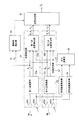
図1は本発明の広角レーダ装置の構成図であり、送信波を目標物に向けて発射し、反射波を受信して対象物体の位置を測定する第1、第2の位置測定部51、52、反射波の強度を検出する反射強度検出部53、54、反射波の強度を用いて目標物の方位を演算する方向演算部55、第1、第2の位置測定部51、52により測定された物体までの距離R1,R2に基づいて同一物体であるか、異なる物体であるかを判定する異物体検出部56、第1、第2の位置測定部51、52が測定した位置データに基づいて目標物の位置を決定する位置決定部57を備えている。第1、第2の位置測定部51、52はそれぞれ送受信部51a,52aおよび位置算出部51b、52bを有している。
第1、第2の送受信部51a, 52aはそれぞれ図6に示す周波数可変発振器1、FM変調電圧発生部2、方向結合器3、ミキサ6、信号処理部7で構成されており、それぞれ中心周波数が異なるFM変調信号(ビームAw,Bw)を送信アンテナATS1,ATS2から送信し、目標物TGからの反射波を受信アンテナATR1,ATR2より受信し、目標物までの距離R1,R2及び相対速度V1,V2を測定する。第1の位置算出部51bは、第1の送受信部51aにより測定された距離R1、相対速度V1並びに方位角θを用いて第1の位置X1,Y1を算出し、また、第2の位置算出部52bは、第2の送受信部52aにより測定された距離R2、相対速度V2並びに方位角θを用いて第2の位置X2,Y2を算出して位置決定部57に入力する。反射強度検出部53、54は第1、第2の受信アンテナATR1,ATR2により受信した信号の強度、すなわち反射波強度を検出し、方向演算部55は第1、第2の反射波強度の差を演算し、該差に基づいて目標物の方向θを演算して出力する。
FIG. 1 is a configuration diagram of a wide-angle radar device according to the present invention. First and second
The first and second transmission /
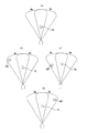
異物体検出部56は第1、第2の送受信部51a,52aが測定した距離R1,R2が等しいか、換言すれば距離R1,R2の差が設定値以下であるかにより広角レーダ装置が1つの目標物を捕捉しているか、異なる2つの物体を補足しているか判断する。すなわち、距離差が設定値より小さければ第1、第2の送受信部51a, 52aは同一物体TGまでの距離を測定したものであり、1つの物体を補足していると判定する(図2(A)参照)。一方、距離差が設定値より大きければ第1、第2の送受信部51a, 52aは異なる物体TG,OBTまでの距離を測定したものであり、異なる2つの物体を補足していると判定する(図2(b)参照)。なお、図2(b)に示すように距離差が大きくて異なる物体であると判定されている状態において、走行により図2(c)に示すように距離差が小さくなって設定値以下になると物体TG,OBTは同一物体とみなされ、物体分離不可能となる。
位置決定部57は、第1、第2の位置測定部51,52により算出された第1の位置X1,Y1、第2の位置X2,Y2及び異物体を検出しているか否かに応じて図3のフローにしたがって目標物の位置を決定して出力する。
The foreign
Whether the
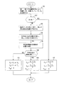
図3は本発明の広角レーダ装置の位置決定フローである。
第1、第2の位置測定部51、52は所定時間T毎に物体までの距離R1,R2及び相対速度V1,V2を測定すると共に、測定距離R1、相対速度V1、方位角θを用いて第1の位置X1,Y1、第2位置X2,Y2を算出する(ステップ100)。
異物体検出部56は第1、第2の位置測定部51,52が測定した距離R1,R2の距離差が許容範囲内であるか判断し(ステップ101)、最大許容値以下であれば広角レーダ装置は1つの目標物を捕捉しており(図2(a))、第1、第2の位置測定部51,52が算出した第1位置X1,Y1、第2位置X2,Y2は同一の目標物TGの位置データであると判定し、次式
XA=(X1+X2)/2 (6a)
YA=(Y1+Y2)/2 (6b)
により目標物の位置XA,YAを計算して出力するとともに、物体分離不可能フラグFEAを"0"にして出力する(ステップ102)。FEAは物体分離不可能を特定するためのフラグであり、FEA=1は測定誤差が大きく、信頼度が小さいことを意味する。
以上のように、広角レーダ装置が1つの目標物TGのみを捕捉している場合には、上式により目標物の位置を測定することができ、測定精度を向上できる。
ステップ101において、距離差が許容範囲外であれば異なる物体(目標物TG、障害物OBT)を検出しているものと判定し(図2(b))、第1、第2の位置測定部51,52が測定した物体のそれぞれの位置履歴データを用いて所定時間T後の各物体の位置を予測する(ステップ103)。ついで、各予測点までの距離を計算し、距離差が設定値以下であるかチェックし、チェック結果を保存する(ステップ104)。
FIG. 3 is a position determination flow of the wide-angle radar device of the present invention.
The first and second
The foreign
X A = (X 1 + X 2 ) / 2 (6a)
Y A = (Y 1 + Y 2 ) / 2 (6b)
Thus, the positions X A and Y A of the target are calculated and outputted, and the object separation impossible flag F EA is set to “0” and outputted (step 102). F EA is a flag for specifying that the object cannot be separated, and F EA = 1 means that the measurement error is large and the reliability is small.
As described above, when the wide-angle radar device captures only one target TG, the position of the target can be measured by the above formula, and the measurement accuracy can be improved.
In
ついで、所定時間T経過後に第1、第2の位置測定部51、52は物体までの距離R1,R2、相対速度V1,V2を測定すると共に、第1、第2の位置(X1,Y1)、(X2,Y2)を計算して位置決定部57に入力する(ステップ105)。位置決定部57は、ステップ104で保存してあるチェック結果を参照し(ステップ106)、予測点までの距離差が設定値以上であれば、2物体のうち着目物体である目標物TGのみを捕捉している第2位置測定部52から入力する第2の位置(X2,Y2)を用いて
XA=X2
YA=Y2
とするとともに、物体分離不可能フラグFEAを"0"にして出力する(ステップ107)。尚、図2(b)に示す状態では第2位置測定部52が目標物のみを補足しているが、図2(d)に示す状態では、第1位置測定部51が目標物のみを補足している。かかる場合には、ステップ107において、
XA=X1
YA=Y1
とする。
以後、走行により、ステップ106において、各予測点までの距離差が設定値以下になれば(図2(c))、位置決定部57は、物体が1つであると判定して(6a),(6b)式により目標物の位置XA,YAを計算して出力するとともに、物体分離不可能フラグFEAを"1"にして出力する(ステップ108)。すなわち、出力する位置データXA,YAは物体分離不可能になった状態における位置データであり、信頼度が低いデータであることを示すフラグFEAを"1"にして出力する。
Next, after the elapse of a predetermined time T, the first and second
X A = X 2
Y A = Y 2
In addition, the object separation impossible flag FEA is set to “0” and output (step 107). In the state shown in FIG. 2 (b), the second
X A = X 1
Y A = Y 1
And
Thereafter, when the distance difference to each prediction point becomes equal to or smaller than the set value in
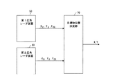
図4は複数(図では2つ)の広角レーダ装置を用いて目標物の位置を決定して出力する位置測定装置の構成図である。広角レーダ装置50,60は図1に示す構成を備え、第1の広角レーダ装置50は測定した目標物の位置データXA,YAと物体分離不可能フラグFEAを出力し、第2の広角レーダ装置60は同様に目標物の位置データXB,YBと物体分離不可能フラグFEBを出力する。目標物位置決定部70は、物体分離不可能フラグFEA,FEBを参照して位置データXA,YA:XB,YBを用いて目標物の位置X,Yを決定して出力する。
図5は目標物位置決定部70の位置決定処理フローである。
まず、第1、第2の広角レーダ装置が測定した目標物の位置が近接しているかチェックする(ステップ201)。すなわち、位置データXA,YA:XB,YBを用いてそれぞれが測定した2点間の距離を求め、距離が設定値以下であるかチェックする。
第1、第2の広角レーダ装置が測定した2点が近接していれば、第1、第2の広角レーダ装置は同一の1つの目標物の位置を測定したものと判定し、次式
X=(XA+XB)/2
Y=(YA+YB)/2
により、目標物の位置(X,Y)を計算して出力する(ステップ202)。
一方、第1、第2の広角レーダ装置が測定した目標物の位置が近接していなければ、物体分離不可能フラグFEA,FEBが何れも0であるかチェックし(ステップ203)、FEA=FEB=0であれば、位置データXA,YA:XB,YBの信頼度は大きいから、第1、第2の広角レーダ装置50,60は同一の目標物の位置を測定したものと判定し、ステップ202により目標物の位置(X,Y)を計算して出力する。
FIG. 4 is a configuration diagram of a position measuring apparatus that determines and outputs the position of a target using a plurality of (two in the figure) wide-angle radar apparatuses. The wide-
FIG. 5 is a position determination process flow of the target
First, it is checked whether the positions of the targets measured by the first and second wide-angle radar devices are close (step 201). That is, the distance between the two points measured by using the position data X A , Y A : X B , Y B is obtained, and it is checked whether the distance is equal to or smaller than the set value.
If the two points measured by the first and second wide-angle radar devices are close to each other, it is determined that the first and second wide-angle radar devices have measured the position of the same target, and
X = (X A + X B ) / 2
Y = (Y A + Y B ) / 2
Thus, the position (X, Y) of the target is calculated and output (step 202).
On the other hand, if the position of the target measured by the first and second wide-angle radar devices is not close, it is checked whether both the object separation impossible flags F EA and F EB are 0 (step 203). If EA = F EB = 0, the reliability of the position data X A , Y A : X B , Y B is high, and therefore the first and second wide-
しかし、FEA,FEBの少なくとも1つが1であれば、FEA,FEBの両方が1であるかチェックし(ステップ204)、FEA,FEBの両方が共に1であれば、位置データXA,YA:XB,YBの測定誤差が大きいから、これらの値を採用せずそれまでの位置軌跡データより目標物の位置を推定し、推定値XP,YPを目標物のX,Y座標として出力する(ステップ205)。
ステップ204において、FEA,FEBの両方が1でなければ、FEAが1であるかチェックし(ステップ206)、FEA=1であればFEB=0であり、第2広角レーダ装置60が測定した位置データXB,YBの信頼度が大きく、第1広角レーダ装置50が測定した位置データXA,YAの測定誤差が大きいから、X=XB,Y=YBとして出力する(ステップ207)。
ステップ206において、FEA=1でなければFEB=1であり、第1広角レーダ装置50が測定した位置データXA,YAの信頼度が大きく、第2広角レーダ装置60が測定した位置データXB,YBの測定誤差が大きいから、X=XA,Y=YAとして出力する(ステップ208)。
以上本発明によれば、測定誤差が大きい位置データを特定でき、しかも、該測定誤差が大きい位置データを除外して目標物の位置を決定できるため、目標物の位置測定精度を向上することができる。
However, F EA, if at least one of the first F EB, F EA, both F EB is checked whether the 1 (step 204), F EA, if both F EB are both 1, the position Data X A , Y A : Since the measurement error of X B , Y B is large, the position of the target is estimated from the position trajectory data so far without adopting these values, and the estimated values X P , Y P are the target Output as the X and Y coordinates of the object (step 205).
In
In
As described above, according to the present invention, position data with a large measurement error can be specified, and the position of the target can be determined by excluding the position data with a large measurement error, so that the position measurement accuracy of the target can be improved. it can.
51,52 第1、第2の位置測定部
53,54 反射強度検出部
55 方向演算部
56 異物体検出部
57 位置決定部
51a,52a 第1、第2の送受信部
51b,52b 第1、第2の位置算出部
51, 52 First and second
Claims (1)
送信波を目標物に向けて発射し、反射波を受信して該目標物の位置を測定すると共に、目標物と異物体とを分離することが不可能になったか監視し、分離不可能になったとき、出力する位置データに分離不可能情報を付加する複数の広角レーダ装置、
各広角レーダ装置から出力されるいずれの位置データにも分離不可能情報が付加されていなければ、各広角レーダ装置から出力される位置データを加重平均して目標物の位置を決定し、いずれか一方の位置データに分離不可能情報が付加されていれば、該分離不可能情報が付加されている位置データを除外して目標物の位置を決定し、いずれの位置データにも分離不可能情報が付加されていれば、それまでの位置データより目標物の位置を推定する目標物位置決定部、
を備え、前記各広角レーダ装置は、
ビーム中心方向が異なり、かつビーム幅が一部重なるように配置した2つのアンテナから目標物に向けて第1、第2の送信波を発射したときにそれぞれ受信する第1、第2の反射波の強度に基づいて前記目標物の方向を演算する方向演算部、
前記第1の反射波を受信して目標物までの距離、目標物に対する相対速度を測定すると共に、該測定結果と前記目標物の方向とを用いて目標物の位置データを算出する第1の位置測定部、
前記第2の反射波を受信して目標物までの距離、目標物に対する相対速度を測定すると共に、該測定結果と前記目標物の方向とを用いて目標物の位置データを算出する第2の位置測定部、
各位置測定部が測定する目標物までの距離の差が設定値より大きければ一方の位置測定部が目標物と異物体を含む2以上の物体を捕捉していると判断する異物体検出部、
1)一方の位置測定部が2以上の物体を捕捉しているときは異物体を捕捉していない他方の位置測定部が算出した位置データを目標物の位置データとして出力し、2)いずれの位置測定部も2以上の物体を捕捉していないときは各位置測定部が算出した位置データを加重平均して目標物の位置データを出力し、3)一方の位置測定部が2以上の物体を捕捉している状態において、それぞれの位置測定部により次に測定する位置を予測し、各予測点までの距離の差が設定値以下であれば、目標物と異物体が分離不可能状態になるものとみなし、各位置測定部が次に測定した位置データを用いて算出した目標物の位置データに分離不可能情報を付加して出力する位置決定部、
を有することを特徴とする位置測定装置。 In a position measuring device that measures the position of a target,
A transmission wave is emitted toward the target, a reflected wave is received and the position of the target is measured, and it is monitored whether it is impossible to separate the target and the foreign body, and the separation is impossible. A plurality of wide-angle radar devices for adding inseparable information to the output position data,
If inseparable information is not added to any position data output from each wide-angle radar device, the position data output from each wide-angle radar device is weighted and averaged to determine the position of the target. If non-separable information is added to one of the position data, the position of the target is determined by excluding the position data to which the non-separable information is added. Is added, the target position determination unit that estimates the position of the target from the previous position data,
Each of the wide-angle radar devices,
First and second reflected waves received respectively when the first and second transmission waves are emitted from two antennas arranged so that the beam center directions are different and the beam widths partially overlap toward the target. A direction calculation unit for calculating the direction of the target based on the intensity of
The first reflected wave is received and the distance to the target and the relative speed with respect to the target are measured, and the position data of the target is calculated using the measurement result and the direction of the target. Position measurement unit,
The second reflected wave is received, and the distance to the target and the relative speed with respect to the target are measured, and the position data of the target is calculated using the measurement result and the direction of the target. Position measurement unit,
A foreign body detection unit that determines that one position measurement unit captures two or more objects including the target and the foreign body if a difference in distance to the target measured by each position measurement unit is greater than a set value ;
1) When one position measuring unit captures two or more objects, the position data calculated by the other position measuring unit not capturing the foreign body is output as the position data of the target. When the position measurement unit has not captured two or more objects, the position data calculated by each position measurement unit is weighted and averaged to output the target position data. 3) One position measurement unit has two or more objects. When the position to be measured next is predicted by each position measurement unit and the difference in distance to each prediction point is less than or equal to the set value, the target object and the foreign body are not separable. A position determination unit that adds and outputs non-separable information to the position data of the target calculated by using the position data measured next by each position measurement unit,
A position measuring device comprising:
Priority Applications (1)
| Application Number | Priority Date | Filing Date | Title |
|---|---|---|---|
| JP2005286756A JP4863679B2 (en) | 2005-09-30 | 2005-09-30 | Position measuring device |
Applications Claiming Priority (1)
| Application Number | Priority Date | Filing Date | Title |
|---|---|---|---|
| JP2005286756A JP4863679B2 (en) | 2005-09-30 | 2005-09-30 | Position measuring device |
Publications (2)
| Publication Number | Publication Date |
|---|---|
| JP2007093542A JP2007093542A (en) | 2007-04-12 |
| JP4863679B2 true JP4863679B2 (en) | 2012-01-25 |
Family
ID=37979429
Family Applications (1)
| Application Number | Title | Priority Date | Filing Date |
|---|---|---|---|
| JP2005286756A Expired - Fee Related JP4863679B2 (en) | 2005-09-30 | 2005-09-30 | Position measuring device |
Country Status (1)
| Country | Link |
|---|---|
| JP (1) | JP4863679B2 (en) |
Families Citing this family (4)
| Publication number | Priority date | Publication date | Assignee | Title |
|---|---|---|---|---|
| JP5659587B2 (en) * | 2010-07-09 | 2015-01-28 | 富士通株式会社 | Radar device, roadside device, and in-vehicle device |
| JP5590463B2 (en) * | 2010-12-17 | 2014-09-17 | 株式会社デンソー | Obstacle monitoring device for vehicles |
| JP6338871B2 (en) | 2014-01-31 | 2018-06-06 | 株式会社デンソーテン | Radar apparatus, vehicle control system, and signal processing method |
| RU2709785C1 (en) * | 2019-03-06 | 2019-12-20 | Акционерное общество "Концерн радиостроения "Вега" | Method of determining extrapolated range values and speed of approach of an aircraft with a radar object |
Family Cites Families (3)
| Publication number | Priority date | Publication date | Assignee | Title |
|---|---|---|---|---|
| JPH11133143A (en) * | 1997-10-31 | 1999-05-21 | Toyota Motor Corp | Radar device |
| JP4258941B2 (en) * | 1999-06-03 | 2009-04-30 | 株式会社デンソー | Radar equipment |
| JP4186744B2 (en) * | 2003-08-01 | 2008-11-26 | 三菱電機株式会社 | Radar equipment |
-
2005
- 2005-09-30 JP JP2005286756A patent/JP4863679B2/en not_active Expired - Fee Related
Also Published As
| Publication number | Publication date |
|---|---|
| JP2007093542A (en) | 2007-04-12 |
Similar Documents
| Publication | Publication Date | Title |
|---|---|---|
| JP4871104B2 (en) | Radar apparatus and signal processing method | |
| JP4593468B2 (en) | Radar equipment | |
| EP2071357B1 (en) | Radar apparatus and method of measuring azimuth angle of target | |
| US10234541B2 (en) | FMCW radar device | |
| JP5122536B2 (en) | Radar equipment | |
| JP2001042034A (en) | Radar device | |
| JP2008107280A (en) | Radar device | |
| JP2009041981A (en) | Object detection system and vehicle equipped with object detection system | |
| JP2014227000A (en) | Vehicle control device, method and program | |
| US11226409B2 (en) | In-vehicle radar device | |
| JP2021513643A (en) | Methods and devices for detecting critical lateral movements | |
| JP2008045880A (en) | Radar system | |
| JP7111181B2 (en) | DETECTION DEVICE, MOBILE SYSTEM, AND DETECTION METHOD | |
| JP2006046962A (en) | Target detection device | |
| JP2014115119A (en) | Object detector | |
| JP4863679B2 (en) | Position measuring device | |
| JP2014006122A (en) | Object detector | |
| JP2013221893A (en) | Radar control device | |
| JP2020148745A (en) | Object tracking device | |
| JP2008304329A (en) | Measuring device | |
| JP2007286033A (en) | Radio detector and method | |
| JP4993431B2 (en) | Method and apparatus for measuring position of target | |
| JP2012168119A (en) | Radar device | |
| EP4045942A1 (en) | Method for estimating an intrinsic speed of a vehicle | |
| WO2019182043A1 (en) | Radar device |
Legal Events
| Date | Code | Title | Description |
|---|---|---|---|
| A621 | Written request for application examination |
Free format text: JAPANESE INTERMEDIATE CODE: A621 Effective date: 20080313 |
|
| A977 | Report on retrieval |
Free format text: JAPANESE INTERMEDIATE CODE: A971007 Effective date: 20100419 |
|
| A131 | Notification of reasons for refusal |
Free format text: JAPANESE INTERMEDIATE CODE: A131 Effective date: 20100427 |
|
| A521 | Request for written amendment filed |
Free format text: JAPANESE INTERMEDIATE CODE: A523 Effective date: 20100628 |
|
| A131 | Notification of reasons for refusal |
Free format text: JAPANESE INTERMEDIATE CODE: A131 Effective date: 20110412 |
|
| A521 | Request for written amendment filed |
Free format text: JAPANESE INTERMEDIATE CODE: A523 Effective date: 20110607 |
|
| TRDD | Decision of grant or rejection written | ||
| A01 | Written decision to grant a patent or to grant a registration (utility model) |
Free format text: JAPANESE INTERMEDIATE CODE: A01 Effective date: 20111108 |
|
| A01 | Written decision to grant a patent or to grant a registration (utility model) |
Free format text: JAPANESE INTERMEDIATE CODE: A01 |
|
| A61 | First payment of annual fees (during grant procedure) |
Free format text: JAPANESE INTERMEDIATE CODE: A61 Effective date: 20111108 |
|
| FPAY | Renewal fee payment (event date is renewal date of database) |
Free format text: PAYMENT UNTIL: 20141118 Year of fee payment: 3 |
|
| R150 | Certificate of patent or registration of utility model |
Ref document number: 4863679 Country of ref document: JP Free format text: JAPANESE INTERMEDIATE CODE: R150 Free format text: JAPANESE INTERMEDIATE CODE: R150 |
|
| LAPS | Cancellation because of no payment of annual fees |