JP2014227000A - Vehicle control device, method and program - Google Patents
Vehicle control device, method and program Download PDFInfo
- Publication number
- JP2014227000A JP2014227000A JP2013107230A JP2013107230A JP2014227000A JP 2014227000 A JP2014227000 A JP 2014227000A JP 2013107230 A JP2013107230 A JP 2013107230A JP 2013107230 A JP2013107230 A JP 2013107230A JP 2014227000 A JP2014227000 A JP 2014227000A
- Authority
- JP
- Japan
- Prior art keywords
- vehicle
- target
- unit
- obstacle
- vehicle control
- Prior art date
- Legal status (The legal status is an assumption and is not a legal conclusion. Google has not performed a legal analysis and makes no representation as to the accuracy of the status listed.)
- Pending
Links
Images


Classifications
-
- B—PERFORMING OPERATIONS; TRANSPORTING
- B60—VEHICLES IN GENERAL
- B60T—VEHICLE BRAKE CONTROL SYSTEMS OR PARTS THEREOF; BRAKE CONTROL SYSTEMS OR PARTS THEREOF, IN GENERAL; ARRANGEMENT OF BRAKING ELEMENTS ON VEHICLES IN GENERAL; PORTABLE DEVICES FOR PREVENTING UNWANTED MOVEMENT OF VEHICLES; VEHICLE MODIFICATIONS TO FACILITATE COOLING OF BRAKES
- B60T7/00—Brake-action initiating means
- B60T7/12—Brake-action initiating means for automatic initiation; for initiation not subject to will of driver or passenger
- B60T7/22—Brake-action initiating means for automatic initiation; for initiation not subject to will of driver or passenger initiated by contact of vehicle, e.g. bumper, with an external object, e.g. another vehicle, or by means of contactless obstacle detectors mounted on the vehicle
-
- B—PERFORMING OPERATIONS; TRANSPORTING
- B60—VEHICLES IN GENERAL
- B60W—CONJOINT CONTROL OF VEHICLE SUB-UNITS OF DIFFERENT TYPE OR DIFFERENT FUNCTION; CONTROL SYSTEMS SPECIALLY ADAPTED FOR HYBRID VEHICLES; ROAD VEHICLE DRIVE CONTROL SYSTEMS FOR PURPOSES NOT RELATED TO THE CONTROL OF A PARTICULAR SUB-UNIT
- B60W10/00—Conjoint control of vehicle sub-units of different type or different function
- B60W10/18—Conjoint control of vehicle sub-units of different type or different function including control of braking systems
- B60W10/184—Conjoint control of vehicle sub-units of different type or different function including control of braking systems with wheel brakes
-
- B—PERFORMING OPERATIONS; TRANSPORTING
- B60—VEHICLES IN GENERAL
- B60W—CONJOINT CONTROL OF VEHICLE SUB-UNITS OF DIFFERENT TYPE OR DIFFERENT FUNCTION; CONTROL SYSTEMS SPECIALLY ADAPTED FOR HYBRID VEHICLES; ROAD VEHICLE DRIVE CONTROL SYSTEMS FOR PURPOSES NOT RELATED TO THE CONTROL OF A PARTICULAR SUB-UNIT
- B60W10/00—Conjoint control of vehicle sub-units of different type or different function
- B60W10/20—Conjoint control of vehicle sub-units of different type or different function including control of steering systems
-
- B—PERFORMING OPERATIONS; TRANSPORTING
- B60—VEHICLES IN GENERAL
- B60W—CONJOINT CONTROL OF VEHICLE SUB-UNITS OF DIFFERENT TYPE OR DIFFERENT FUNCTION; CONTROL SYSTEMS SPECIALLY ADAPTED FOR HYBRID VEHICLES; ROAD VEHICLE DRIVE CONTROL SYSTEMS FOR PURPOSES NOT RELATED TO THE CONTROL OF A PARTICULAR SUB-UNIT
- B60W30/00—Purposes of road vehicle drive control systems not related to the control of a particular sub-unit, e.g. of systems using conjoint control of vehicle sub-units, or advanced driver assistance systems for ensuring comfort, stability and safety or drive control systems for propelling or retarding the vehicle
- B60W30/08—Active safety systems predicting or avoiding probable or impending collision or attempting to minimise its consequences
- B60W30/09—Taking automatic action to avoid collision, e.g. braking and steering
-
- B—PERFORMING OPERATIONS; TRANSPORTING
- B60—VEHICLES IN GENERAL
- B60W—CONJOINT CONTROL OF VEHICLE SUB-UNITS OF DIFFERENT TYPE OR DIFFERENT FUNCTION; CONTROL SYSTEMS SPECIALLY ADAPTED FOR HYBRID VEHICLES; ROAD VEHICLE DRIVE CONTROL SYSTEMS FOR PURPOSES NOT RELATED TO THE CONTROL OF A PARTICULAR SUB-UNIT
- B60W30/00—Purposes of road vehicle drive control systems not related to the control of a particular sub-unit, e.g. of systems using conjoint control of vehicle sub-units, or advanced driver assistance systems for ensuring comfort, stability and safety or drive control systems for propelling or retarding the vehicle
- B60W30/08—Active safety systems predicting or avoiding probable or impending collision or attempting to minimise its consequences
- B60W30/095—Predicting travel path or likelihood of collision
- B60W30/0956—Predicting travel path or likelihood of collision the prediction being responsive to traffic or environmental parameters
-
- B—PERFORMING OPERATIONS; TRANSPORTING
- B60—VEHICLES IN GENERAL
- B60T—VEHICLE BRAKE CONTROL SYSTEMS OR PARTS THEREOF; BRAKE CONTROL SYSTEMS OR PARTS THEREOF, IN GENERAL; ARRANGEMENT OF BRAKING ELEMENTS ON VEHICLES IN GENERAL; PORTABLE DEVICES FOR PREVENTING UNWANTED MOVEMENT OF VEHICLES; VEHICLE MODIFICATIONS TO FACILITATE COOLING OF BRAKES
- B60T2201/00—Particular use of vehicle brake systems; Special systems using also the brakes; Special software modules within the brake system controller
- B60T2201/02—Active or adaptive cruise control system; Distance control
- B60T2201/024—Collision mitigation systems
-
- B—PERFORMING OPERATIONS; TRANSPORTING
- B60—VEHICLES IN GENERAL
- B60W—CONJOINT CONTROL OF VEHICLE SUB-UNITS OF DIFFERENT TYPE OR DIFFERENT FUNCTION; CONTROL SYSTEMS SPECIALLY ADAPTED FOR HYBRID VEHICLES; ROAD VEHICLE DRIVE CONTROL SYSTEMS FOR PURPOSES NOT RELATED TO THE CONTROL OF A PARTICULAR SUB-UNIT
- B60W2554/00—Input parameters relating to objects
- B60W2554/80—Spatial relation or speed relative to objects
- B60W2554/801—Lateral distance
-
- B—PERFORMING OPERATIONS; TRANSPORTING
- B60—VEHICLES IN GENERAL
- B60W—CONJOINT CONTROL OF VEHICLE SUB-UNITS OF DIFFERENT TYPE OR DIFFERENT FUNCTION; CONTROL SYSTEMS SPECIALLY ADAPTED FOR HYBRID VEHICLES; ROAD VEHICLE DRIVE CONTROL SYSTEMS FOR PURPOSES NOT RELATED TO THE CONTROL OF A PARTICULAR SUB-UNIT
- B60W2554/00—Input parameters relating to objects
- B60W2554/80—Spatial relation or speed relative to objects
- B60W2554/804—Relative longitudinal speed
-
- G—PHYSICS
- G06—COMPUTING; CALCULATING OR COUNTING
- G06V—IMAGE OR VIDEO RECOGNITION OR UNDERSTANDING
- G06V20/00—Scenes; Scene-specific elements
- G06V20/50—Context or environment of the image
- G06V20/56—Context or environment of the image exterior to a vehicle by using sensors mounted on the vehicle
- G06V20/58—Recognition of moving objects or obstacles, e.g. vehicles or pedestrians; Recognition of traffic objects, e.g. traffic signs, traffic lights or roads
Abstract
Description
本発明は、運転者の運転操作に適応した障害物検出を行う車両制御装置、その方法およびそのプログラムに関する。 The present invention relates to a vehicle control device that performs obstacle detection adapted to a driving operation of a driver, a method thereof, and a program thereof.
最近、自動車の運転支援のために、車両前方に搭載したレーダ装置を用いた、車速制動装置や、先行車両追従システムや、衝突軽減ブレーキシステムなどといった車速制御システムが開発され実施されている。 Recently, vehicle speed control systems such as a vehicle speed braking device, a preceding vehicle tracking system, and a collision mitigation braking system using a radar device mounted in front of the vehicle have been developed and implemented for driving assistance of automobiles.
このような車速制御装置や、先行車両追従システムや、衝突軽減ブレーキシステム等の車速制御システムは、レーダ装置によって対象車両や障害物を検知して、その検知結果に応じて、車両の制動等を行うものである。しかし、このような車速制御システムにおいては様々な課題があり、これらの課題について多くの特許文献が知られている。 Such vehicle speed control devices, preceding vehicle tracking systems, collision reduction brake systems, and other vehicle speed control systems detect target vehicles and obstacles with radar devices, and perform vehicle braking or the like according to the detection results. Is what you do. However, there are various problems in such a vehicle speed control system, and many patent documents are known for these problems.
特許文献1は、レーダで検出した物標データの内、路面に埋め込まれた反射物標を、前方車両等の物標と区別できずに誤認識してしまうという課題を解決するもので、対象物標の相対速度が所定量以上である場合、これを反射物標であるとして除外する車速制御システムを開示している。
なお、ここで物標とは、レーダ波を反射したポイントを表す指標である。物標を特定するための物標情報は、一般に、車両から物標までの距離、車両に対する物標の相対速度、物標が存在する方位を含んでいる。
Here, the target is an index representing a point where the radar wave is reflected. The target information for specifying the target generally includes the distance from the vehicle to the target, the relative speed of the target with respect to the vehicle, and the direction in which the target exists.
しかし、特許文献1に記載された車速制御システムは、レーダで検出された物標が回避したり追跡したりすべきである先方障害物であるかどうかについて、運転者の操作状況にかかわらず一律の判断基準により判断している。この結果、例えば、運転者の操作状況が進路変更や車線変更の際には、急減速または急停止した先行車両を先方障害物とする認識が間に合わなくなり異常接近する場合がある。
However, the vehicle speed control system described in
ここで、図11を用いて進路変更を行う際に先行車両が異常接近する場合を具体的に説明する。図11において、市街地などで自己の車両Vが前方の駐車している車両Cを避けるために進路変更を行う場合、運転者は隣接車線に接近する車両がないか後方確認を実施する。このような場合、例えば、自己の車両Vの二つ先の車両Aが急に減速または停車すると、後続車両Bはそれに伴い減速または停車する。しかし、自己の車両Vの運転者は後方確認中であるので、このような前方の車両Aの変化が起きても車両Bの減速または停車に気付くのが遅れることがあり、自己の車両Vは車両Bに異常に接近したり追突する場合も考えられる。 Here, the case where the preceding vehicle abnormally approaches when changing the course will be specifically described with reference to FIG. In FIG. 11, when the course is changed in order to avoid the vehicle C in which the vehicle V is parked ahead in an urban area or the like, the driver performs a rearward confirmation whether there is a vehicle approaching the adjacent lane. In such a case, for example, when the second vehicle A ahead of the own vehicle V suddenly decelerates or stops, the following vehicle B decelerates or stops accordingly. However, since the driver of the own vehicle V is confirming the rear side, even if such a change of the vehicle A ahead occurs, it may be delayed to notice the deceleration or stop of the vehicle B. There may be cases where the vehicle B approaches the vehicle B abnormally or makes a rear-end collision.
一方、上述した特許文献1が示すような車速制御システムや、障害物検知装置においては、運転者の操作意志がない(例えば、居眠り等)場合、制動や操舵等の操作がない場合に作動するシステムである。そのため、特許文献1に示すシステムでは、図11のような運転者が運転操作を行っている状況では障害物検出機能が十分適切には作動しない場合があるという問題がある。
On the other hand, the vehicle speed control system and the obstacle detection device as shown in
本発明はこのような問題を解決するためになされたものであり、運転操作中でも障害物を確実に検出して安定した車両制御を行うことができる車両制御装置、その方法およびそのプログラムを提供することを目的とする。 The present invention has been made to solve such a problem, and provides a vehicle control device, a method thereof, and a program thereof capable of reliably detecting an obstacle even during a driving operation and performing stable vehicle control. For the purpose.
(1)本発明の一実施形態である車両制御装置は、前記した課題を解決するために、車両の外界の特徴に基づいて物標を検出する車載用外界センシング部と、前記車両の操作を行う操作部と、前記操作部への操作がない場合は第1動作モード、前記操作部への操作がある場合は前記第1動作モードと異なる第2動作モードと判定する判定部と、前記判定部が前記第2動作モードと判定した場合は、前記第1動作モードと判定した場合よりも短い時間において、前記車載用外界センシング部が検出する物標に基づいて障害物を決定し、前記決定した障害物に応じて車両を制御する制御部を具備している。 (1) In order to solve the above-described problem, a vehicle control apparatus according to an embodiment of the present invention includes an in-vehicle external field sensing unit that detects a target based on characteristics of the external field of the vehicle, and an operation of the vehicle. A determination unit that determines a first operation mode when there is no operation to the operation unit, a determination unit that determines a second operation mode different from the first operation mode when there is an operation to the operation unit, and the determination When the part is determined to be the second operation mode, the obstacle is determined based on the target detected by the in-vehicle external field sensing unit in a shorter time than when the first operation mode is determined, and the determination A control unit for controlling the vehicle according to the obstacle is provided.
これによれば、前記車両制御装置は、運転者の操作が無い場合は通常の第1動作モードによって、運転者の操作、例えば方向指示器や操舵がある場合は第2動作モードによって障害物を決定する。従って、現在の「運転操作」が運転者による進路変更がある際にこれを「進路変更モード(第2動作モード)」と判定する。そして、前記車両制御装置は、「進路変更モード(第2動作モード)」では、例えば対象物データが障害物か否かを確定するための期間を「通常モード(第1動作モード)」よりも早める等の「運転操作」に応じた判断基準の工夫を施す。これにより、前記車両制御装置は、進路変更中に自車両が前方車両と急に接近する場合でも、確実に障害物(前方の車両等)を検出し回避することができる。 According to this, the vehicle control device detects the obstacle by the normal first operation mode when there is no driver's operation, and by the second operation mode when there is a driver's operation, for example, a direction indicator or steering. decide. Accordingly, when the current “driving operation” has a course change by the driver, this is determined as a “course change mode (second operation mode)”. In the “route change mode (second operation mode)”, for example, the vehicle control apparatus sets a period for determining whether the object data is an obstacle as compared with the “normal mode (first operation mode)”. Devise judgment criteria according to “driving operation” such as advancement. Thus, the vehicle control device can reliably detect and avoid an obstacle (such as a vehicle ahead) even when the host vehicle suddenly approaches the vehicle ahead while changing the course.
(2)前記(1)記載の車両制御装置であって、前記操作部は、前記車両の進行方向を指示するハンドルおよび前記車両の進行方向を表示する方向指示器の内の一方または両方であることを特徴とする。 (2) In the vehicle control device according to (1), the operation unit is one or both of a handle that indicates a traveling direction of the vehicle and a direction indicator that displays the traveling direction of the vehicle. It is characterized by that.
これによれば、前記車両制御装置は、特に、運転者が例えば方向指示器を操作して進路変更する場合(進路変更モード)について、方向指示器を操作しない場合(通常モード)と異なる判断基準によって「障害物」の有無を判断する。これにより、前記車両制御装置は、方向指示器を操作して進路変更中に、急に前方車両が減速し停車するような場合でも、迅速な判断基準で、確実に障害物(前方の車両等)を検出し回避することができる。 According to this, the vehicle control device is different from the case where the driver does not operate the direction indicator (normal mode) particularly when the driver changes the course by operating the direction indicator (route change mode), for example. The presence or absence of an “obstacle” is determined by As a result, the vehicle control device ensures that an obstacle (such as a vehicle ahead) can be reliably detected based on a quick judgment criterion even when the vehicle ahead suddenly decelerates and stops while operating the direction indicator. ) Can be detected and avoided.
(3)前記(1)または(2)のいずれか1つに記載の車両制御装置であって、前記車載用外界センシング部が検出する物標は物標情報により表現され、前記物標情報は、前記車両と物標までの距離、前記車両に対する物標の相対速度、および前記物標が存在する方向を含むことを特徴とする。
これによれば、前記車両制御装置は、必要な物標情報により、運転者の操作状況に応じて確実に障害物(前方の車両等)を検出し、これに基づく車両制御が可能となる。
(3) In the vehicle control device according to any one of (1) and (2), the target detected by the in-vehicle external field sensing unit is expressed by target information, and the target information is And a distance between the vehicle and the target, a relative speed of the target with respect to the vehicle, and a direction in which the target exists.
According to this, the said vehicle control apparatus detects an obstruction (front vehicle etc.) reliably according to a driver | operator's operation condition with required target information, and vehicle control based on this becomes possible.
(4)前記(1)ないし(3)のいずれか1つに記載の車両制御装置であって、前記制御部は、前記第1動作モードでは、前記車両の速度とハンドルの角速度に基づいて推定軌跡を求め、この推定軌跡と物標までの距離に基づいて前記障害物を決定し、前記第2動作モードでは、前記障害物の移動方向を求め、前記障害物の移動方向に基づいて、当該車両から前記障害物までの距離によって前記障害物を決定することを特徴とする。 (4) In the vehicle control device according to any one of (1) to (3), in the first operation mode, the control unit estimates based on a speed of the vehicle and an angular speed of a steering wheel. A trajectory is obtained, the obstacle is determined based on the estimated trajectory and the distance to the target. In the second operation mode, the movement direction of the obstacle is obtained, and based on the movement direction of the obstacle, The obstacle is determined according to a distance from a vehicle to the obstacle.
これによれば、前記車両制御装置は、特に車両が進路変更を行っており前方車両が急に停車し、図5に後述するような方法で車両の軌跡を予測できない場合でも、確実に障害物を検出して、これに基づく車両制御が可能となる。 According to this, the vehicle control device ensures that an obstacle is sure even when the vehicle is changing course and the preceding vehicle stops suddenly and the vehicle trajectory cannot be predicted by the method described later in FIG. And vehicle control based on this can be performed.
(5)前記(1)ないし(4)のいずれか1つに記載の車両制御装置であって、前記制御部は、前記決定した障害物に車両が衝突することを回避するべく車両の制動を制御することを特徴とする。
これによれば、前記車両制御装置は、運転者の操作状況に応じて検出した障害物に基づいて、車両が障害物に衝突することを確実に回避することができる。
(5) The vehicle control device according to any one of (1) to (4), wherein the control unit brakes the vehicle to avoid collision of the vehicle with the determined obstacle. It is characterized by controlling.
According to this, the vehicle control device can reliably avoid the vehicle from colliding with the obstacle based on the obstacle detected according to the operation state of the driver.
(6)前記(1)ないし(5)のいずれか1つに記載の車両制御装置であって、前記制御部は、前記決定した障害物と車両との間隔が一定となるように車両の制動を制御することを特徴とする。
これによれば、前記車両制御装置は、運転者の操作状況に応じて検出した障害物に基づいて、車両と障害物である前方車両との間隔を確実に一定にすることができる。
(6) The vehicle control device according to any one of (1) to (5), wherein the control unit brakes the vehicle so that a distance between the determined obstacle and the vehicle is constant. It is characterized by controlling.
According to this, the said vehicle control apparatus can make constant the space | interval of a vehicle and the front vehicle which is an obstruction based on the obstruction detected according to the driver | operator's operation condition.
(7)前記(1)ないし(6)のいずれか1つに記載の車両制御装置であって、前記車載用外界センシング部は、障害物に電波を照射し、その反射波を受信し前記反射波に基づき物標を検出するレーダ部であることを特徴とする。
これによれば、前記車両制御装置は、レーダ部のレーダ波を用いることにより確実に障害物を検出して、障害物に応じた車両制御を行うことができる。
(7) In the vehicle control device according to any one of (1) to (6), the in-vehicle external field sensing unit irradiates an obstacle with a radio wave, receives a reflected wave, and receives the reflected wave. A radar unit that detects a target based on a wave.
According to this, the vehicle control device can reliably detect an obstacle by using the radar wave of the radar unit, and can perform vehicle control according to the obstacle.
(8)前記(1)ないし(7)のいずれか1つに記載の車両制御装置であって、前記車両に搭載され車両前方の映像信号を出力するカメラ部をさらに具備し、前記制御部は、前記車載用外界センシング部が出力する物標と前記カメラ部が出力する障害物データの両方に基づいて前記障害物を決定することを特徴とする。
これによれば、前記車両制御装置は、レーダ部からの信号だけでなくカメラ部からの障害物データにより障害物の誤判断を回避して、確実に障害物に対する車両制御を行うことができる。
(8) The vehicle control device according to any one of (1) to (7), further including a camera unit that is mounted on the vehicle and outputs a video signal in front of the vehicle, wherein the control unit includes: The obstacle is determined based on both the target output from the in-vehicle external field sensing unit and the obstacle data output from the camera unit.
According to this, the vehicle control device can avoid the erroneous determination of the obstacle by the obstacle data from the camera unit as well as the signal from the radar unit, and can reliably perform the vehicle control on the obstacle.
(9)前記(1)ないし(6)のいずれか1つに記載の車両制御装置であって、前記車載用外界センシング部は、前記車両に搭載され前記車両の前方の映像信号を出力するカメラ部であることを特徴とする。
これによれば、前記車両制御装置は、カメラ部の光学カメラ素子を用いることにより確実に障害物を検出して、障害物に応じた車両制御を行うことができる。
(9) The vehicle control device according to any one of (1) to (6), wherein the in-vehicle external sensing unit is mounted on the vehicle and outputs a video signal in front of the vehicle. It is a part.
According to this, the said vehicle control apparatus can detect an obstruction reliably by using the optical camera element of a camera part, and can perform vehicle control according to the obstruction.
(10)本発明の一実施形態である車両制御方法は、車両の操作がない場合は第1動作モード、前記車両の操作がある場合は第2動作モードと判定する判定工程と、前記判定工程で判定された第1動作モードに応じた第1決定基準または前記第2動作モードに応じた前記第1決定基準とは異なる第2決定基準によって、前記車両に搭載した車載用外界センシング部が検出した物標に基づいて障害物を決定する決定工程と、前記決定工程が決定した障害物に応じて前記車両を制御する制御工程を有している。
これによれば、前記車両制御方法は、前記車両制御装置と同様に、運転者の現在の運転操作に適合して確実に障害物(前方の車両等)を検出し回避することができる。
(10) The vehicle control method according to an embodiment of the present invention includes a determination step of determining a first operation mode when there is no vehicle operation, and a second operation mode when there is an operation of the vehicle, and the determination step. The vehicle-mounted external sensing unit mounted on the vehicle detects the first determination criterion according to the first operation mode determined in
According to this, the vehicle control method can detect and avoid an obstacle (such as a vehicle ahead) reliably in conformity with the current driving operation of the driver, similarly to the vehicle control device.
(11)本発明の一実施形態である車両制御プログラムは、コンピュータを前記(1)記載の車両制御装置として機能させることを特徴としている。
これによれば、前記車両制御装置および前記車両制御方法と同様に、前記車両制御プログラムは、運転者の現在の運転操作に適合して確実に障害物(前方の車両等)を検出し回避することができる。
(11) A vehicle control program according to an embodiment of the present invention is characterized by causing a computer to function as the vehicle control device described in (1).
According to this, similarly to the vehicle control device and the vehicle control method, the vehicle control program reliably detects and avoids an obstacle (such as a vehicle ahead) in conformity with the current driving operation of the driver. be able to.
本発明に係る車両制御装置によれば、障害物を確実に検出して車両制御を行うことができる。同様に、本発明に係る車両制御方法および車両制御プログラムによれば、障害物を確実に検出して車両制御を行うことができる。 According to the vehicle control device of the present invention, vehicle control can be performed by reliably detecting an obstacle. Similarly, according to the vehicle control method and the vehicle control program according to the present invention, it is possible to reliably detect an obstacle and perform vehicle control.
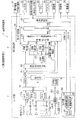
以下、本発明の実施形態に係る車両制御装置について、図面を参照して詳細に説明する。図1は、本発明の第1実施形態に係る車両制御装置の電気的構成を示すブロック図である。
<<第1実施形態に係る車両制御装置>>
[車両制御装置の構成]
本発明の第1実施形態に係る車両制御装置1は、路上を走行する車両に備えられており、図1において、レーダ部2(車載用外界センシング部)と、信号処理部3と、車両制御装置1の動作を制御する制御部5を有している。
Hereinafter, a vehicle control device according to an embodiment of the present invention will be described in detail with reference to the drawings. FIG. 1 is a block diagram showing an electrical configuration of the vehicle control apparatus according to the first embodiment of the present invention.
<< Vehicle control device according to the first embodiment >>
[Configuration of vehicle control device]
A
なお、車載用外界センシング部の一例として下記の実施形態では、レーダ部2である電子走査型レーダ装置(FMCW(Frequency Modulated Continuous Wave)方式ミリ波レーダ)を挙げている。しかし、本発明の第1実施形態に係る車両制御装置1が用いる車載用外界センシング部は、このレーダ装置に限定されるものではなく、例えば、レーザレーダ装置であってもよい。
In the following embodiment, an electronic scanning radar device (FMCW (Frequency Modulated Continuous Wave) type millimeter wave radar) which is the
すなわち、車載用外界センシング部は、車両に搭載が可能で、車両走行時の障害となる障害物の検出機能を有する装置であればどのようなものでもよい。例えば、車載用外界センシング部は、後記の図10において説明される光学式のカメラ部39であってもよく、また、複数の検出装置を組み合わせたものでも良い。
制御部5は、マイクロコンピュータおよびRAM(Random Access Memory)、ROM(Read Only memory)等の記憶装置を少なくとも有している。制御部5は、車両制御装置1の全体的な制御を行うべく、レーダ部2の各構成素子および信号処理部3の各構成素子にそれぞれ接続されている。制御部5は、ROM等に格納されたコンピュータプログラムである車両制御プログラムに基づいて、図1に示す車両制御装置1のレーダ部2および信号処理部3の各部の制御を行う。
In other words, the in-vehicle external field sensing unit may be any device as long as it can be mounted on a vehicle and has a function of detecting an obstacle that becomes an obstacle when the vehicle travels. For example, the in-vehicle external field sensing unit may be an
The
車両制御装置1の信号処理部3は、車両V(図11)の機能である方向指示器等の操作機器(操作部)31と、車両の操舵を行うためのハンドル32と、車速センサ等の車両状態検出部33と、警報音を鳴らすブザー34と、操作情報や警報情報を表示するディスプレイ35と、車両の制動機能を有する制動部36と、車両の加速機能を有する駆動部37と、車両の進行方向を決定する操舵部38とにそれぞれ接続されている。
The
ここで、車両制御装置1のレーダ部2は、一例として前記した電子走査型レーダ装置であり、障害物に電波を照射し、その反射波を受信して、この反射波に基づき物標を検出する検出装置である。図1において、レーダ部2は、受信アンテナ11a〜11nと、ミキサ12a〜12nと、送信アンテナ13と、分配器14と、フィルタ15a〜15nと、スイッチ16と、A/Dコンバータ17と、三角波生成部19と、VCO(Voltage Controlled Oscillator)20とを有している。
Here, the
ここで、受信アンテナ11a〜11nは、物標に到達した送信波が反射し、この対象物から到来する反射波(到来波とも言う)を受信波として受信するアンテナ素子である。
また、各ミキサ12a〜12nは、送信アンテナ13が送信した送信波と、各受信アンテナ11a〜11nが受信し増幅器により増幅した受信波とを混合し、それぞれの周波数差に対応したビート信号を生成する素子である。
このようにビート信号とは、受信アンテナ11a〜11nが受信した受信波から障害物を検出するために、送信波に対する受信波の大きさに基づいて、複数の周波数毎に生成された複数の信号である。ここで、各ビート信号の各周波数は、受信アンテナ11a〜11nと障害物との距離に対応しており、周波数の大きさに基づいて距離を検出することができる。
Here, the receiving
Each
As described above, the beat signal is a plurality of signals generated for each of a plurality of frequencies based on the magnitude of the received wave with respect to the transmitted wave in order to detect an obstacle from the received wave received by the receiving
送信アンテナ13は、分配器14から供給される送信波を放射するアンテナ素子である。
また、分配器14は、周波数変調されたVCO20からの送信波を、前記ミキサ12a〜12nおよび送信アンテナ13に分配する素子である。
また、フィルタ15a〜15n各々は、各受信アンテナ11a〜11nで取得し各々ミキサ12a〜12nにおいて生成されたたCh1〜Chnのビート信号に対して帯域制限を行い、この帯域制限されたビート信号をスイッチ16へ出力する素子である。
The transmission antenna 13 is an antenna element that radiates a transmission wave supplied from the
The
Each of the
また、スイッチ16は、フィルタ15a〜15n各々を通過した各受信アンテナ11a〜11nに対応したCh1〜Chnのビート信号を、制御部5が出力するサンプリング信号に対応して順次切り替えて、A/Dコンバータ17に出力する素子である。
また、A/Dコンバータ17は、前記スイッチ16から前記サンプリング信号に同期して入力される各受信アンテナ11a〜11n各々に対応したCh1〜Chnのビート信号を、前記サンプリング信号に同期してA/D変換してデジタル信号に変換し、信号処理部3におけるメモリ21の波形記憶領域に順次記憶させる回路である。
In addition, the
Further, the A /
また、車両制御装置1の信号処理部3は、上述した制御部5によってその動作が制御される。信号処理部3は、メモリ21と、受信強度算出部22と、DBF検知部23と、距離検出部24と、速度検出部25と、方位検出部26と、物標引継ぎ処理部27と、モード判定部28と、物標処理部29と、車両制御部30を有している。
なお、車両制御部30の機能(障害物制動機能、先行車両追従機能等)は、車両制御装置1の機能としてではなく、車両Vの図示しない車両制御部の本来の制動機能に追加される付加機能として実現することも可能である。
The operation of the
The functions of the vehicle control unit 30 (obstacle braking function, preceding vehicle following function, etc.) are not added as functions of the
信号処理部3内のメモリ21は、A/Dコンバータ17においてデジタル変換されたデジタル信号を各受信アンテナ11a〜11nに対応したチャンネルごとに格納する記憶素子である。
受信強度算出部22は、メモリ21に格納された各受信アンテナ11a〜11nに対応したチャンネルごとのビート信号をフーリエ変換し、信号レベルを算出して、距離検出部24、速度検出部25、DBF処理部23、物標処理部29に出力する処理部である。
The
The reception
DBF(Digital Beam Forming)処理部23は、受信強度算出部22から入力される各アンテナに対応した時間軸でフーリエ変換された複素データを、アンテナの配列方向にさらにフーリエ変換し、すなわち空間軸フーリエ変換を行って、角度分解能に対応した角度チャネル毎のスペクトルの強度を示す空間複素数データを算出して方位検出部26に出力する処理部である。
距離検出部24は、受信強度算出部22から入力される周波数変調幅Δf、上昇部分の対象物周波数および下降部分の対象物周波数から、距離を算出して物標引継ぎ処理部27に出力する処理部である。
A DBF (Digital Beam Forming)
The
速度検出部25は、受信強度算出部22から入力される中心周波数、上昇部分の対象物周波数および下降部分の対象物周波数から、相対速度を算出して物標引継ぎ処理部27に出力する処理部である。
方位検出部26は、DBF処理部23から入力されるビート周波数毎の空間複素数のうち、一番振幅が大きな値を取る角度を、対象物が存在する方位として算出して物標引継ぎ処理部27に出力する処理部である。
The
The azimuth detecting unit 26 calculates the angle having the largest amplitude among the spatial complex numbers for each beat frequency input from the
物標引継ぎ処理部27は、距離検出部24、速度検出部25、方位検出部26から入力される今回算出した物標(車両Vから物標までの距離、車両Vに対する物標の相対速度、車両Vを基準とした物標が存在する方位)と、メモリ21から読み出した1サイクル前に算出された物標の差分が所定量以下であるとき、同一の物標と判定して物標処理部29に出力する処理部である。
物標とは、前記したように、レーダ波を反射したポイントを表す指標である。ここで言う物標情報は、車両Vから物標までの距離、車両Vに対する物標の相対速度、物標が存在する方位(予め規定された検出基準軸に対して反射波が到来した方位)を少なくとも含んでいる。
The target
As described above, the target is an index representing the point where the radar wave is reflected. The target information here refers to the distance from the vehicle V to the target, the relative speed of the target with respect to the vehicle V, and the direction in which the target is present (the direction in which the reflected wave has arrived with respect to the predefined detection reference axis). At least.
モード判定部28は、方向指示器等の操作機器31からの操作情報に基づいて、物標出力処理部が一例として通常モードで動作すべきか進路変更モード等で動作すべきかを判定して物標処理部29に出力する処理部である。このモード判定部28は、ここでは、一例として操作機器31からの操作情報の少なくとも1つ好ましくは2つを受けることで、動作モードの切替のトリガとしている。
物標処理部29は、レーダ部2が検出した反射波(到来波)に基づいて検出した複数の物標から「障害物」となる物標を仮定し、所定期間連続して「障害物」と仮定されれば、その物標を「障害物」と決定する。
For example, the
The
ここにおいて、物標処理部29は、一例として通常モードまたは進路変更モード等に準じた判断基準に基づいて、複数の物標の中から「障害物」となる物標を決定して、この「障害物」の物標を車両制御部30に出力する。
この物標処理部29が行う障害物処理は、図4、図6、図8、図9のフローチャートに詳細に説明される。
Here, as an example, the
The obstacle processing performed by the
車両制御部30は、物標処理部29の判定に基づいて、ブザー34またはディスプレイ35に警告を行ったり、車両Vの制動または操舵を行う制御部である。車両制御部30が行う処理は、後記するように図4、図6、図8、図9のフローチャートが示す障害物処理に詳細に説明される。
The
ここで、操作機器31とは、車両の進行方向を表示する方向指示器の他に、それぞれ図示しない、車両の加速を指示するべく運転者が踏み込むためのアクセルペダル、車両の走行にブレーキを指示するべく運転者が踏み込むためのブレーキペダル、雨天時等にフロントガラス等を清掃するためのワイパーを動作させるワイパー操作部、変速機のレンジ位置の変更を指示するシフト装置等の車両Vの多くの操作部を含む。
また、ハンドル32は、車両Vの操舵を行うためのもので、図示しないパワーステアリング機能により、運転者は少ない力で車両の進行方向を操舵することができる。
Here, the operating
The
また、車速センサ33は、車両Vの走行速度を検出して、物標処理部29等に検出信号を供給する速度検出素子である車速センサを含む。車速センサ33等は、車速センサ33以外に、例えば、図示しない変速機のシフトレンジ位置を検出するセンサ、また、それ以外にも、車両Vの動作状態を検出して検出信号を出力する複数のセンサを含んでいる。
また、ブザー34は、例えば車両Vが、予め決められた所定距離より接近した場合、先方障害物(他の車両等)に近づいた場合に警報を鳴らすために設けられた警報器である。
ディスプレイ35は、速度や走行距離等の操作情報を表示すると共に、車両Vが、先方障害物(他の車両等)に接近し過ぎた場合に、前記のブザー34と共に警報画面を表示するための液晶画面等の表示装置である。
The
Further, the
The
制動部36は、運転者の図示しないブレーキペダルの操作または制御信号等に応じて例えばブレーキ液圧を制御し、車両の減速および停止を制御する、車両Vに備えられた機構である。
駆動部37は、運転者の図示しないアクセルペダルの操作または制御信号等に応じて例えばスロットル開度を制御し、車両の駆動および加速を制御する、車両Vに備えられた機構である。
操舵部38は、運転者の操作に応じて車両の進行方向を決定するべく前輪の角度を決定する、車両Vに備えられた機構である。
The
The
The
[車両制御装置のレーダ部2の動作]
次に、図1を参照して、本実施形態による電子走査型のレーダ部2の動作を説明する。制御部5の制御下において、三角波生成部19は三角波信号を生成し、VCO(Voltage Control Oscillator)10に供給する。分配器14は、VCO20からの周波数変調された送信波を、前記ミキサ12a〜12nおよび送信アンテナ13に分配する。
[Operation of
Next, the operation of the electronic scanning
この送信波が、送信アンテナ13から車両Vの進行方向へと照射される。受信アンテナ11a〜11nは、この送信波の対象物からの反射波を受信して受信波を得る。
受信波は、レーダと対象物との距離に応じて遅延されて受信され、さらに、ドップラー効果によって対象物との相対速度に応じて、送信波に対して周波数方向に変動する。
This transmission wave is irradiated from the transmission antenna 13 in the traveling direction of the vehicle V. The receiving
The received wave is received after being delayed according to the distance between the radar and the object, and further varies in the frequency direction with respect to the transmitted wave according to the relative speed with respect to the object due to the Doppler effect.
制御部5の制御下において、各受信アンテナ11a〜11nが受信した各受信波は増幅器により増幅され、ミキサ12a〜12nにより送信アンテナ13から送信される送信波と混合されて、各周波数差に対応したビート信号が生成される。これらの各ビート信号は、フィルタ15a〜15n各々を通過し、制御部5から入力されるサンプリング信号に対応してスイッチ16を順次切り替えてA/Dコンバータ17に出力される。A/Dコンバータ17でデジタル化された各ビート信号は、それぞれメモリ21の波形記憶領域に格納される。
Under the control of the
[車両制御装置の信号処理部3の動作]
次に、本実施形態における車両制御装置の信号処理部3において行われる、物標の検出、複数の物標中の「障害物」の決定、決定した「障害物」に応じた車両の制御処理の動作について、詳細に説明する。
[Operation of
Next, target detection, determination of “obstacles” in a plurality of targets, and vehicle control processing according to the determined “obstacles” performed in the
受信強度算出部22は、メモリ21に格納された複素数データに対して、フーリエ変換を行う。ここで、フーリエ変換後の複素数データの振幅を信号レベルと呼ぶこととする。受信強度算出部22は、何れかのアンテナにおける複素数データまたは全アンテナの複素数データの加算値を周波数スペクトル化することにより、スペクトルの各ピーク値に対応するビート周波数、すなわち距離に依存した対象物の存在として検出することができる。ここで、全アンテナの複素数データの加算により、ノイズ成分が平均化されてS/N比が向上する。
The reception
そして、受信強度算出部22は、ビート周波数毎の信号レベルから、予め設定された数値(閾値)を超える信号レベルを検出することによって、対象物が存在していることを判定する。ここで、信号レベルのピーク値を受信波の強度と称す。
Then, the reception
受信強度算出部22は、信号ビート周波数毎の信号レベルから、レベルのピークを検出した場合、ピーク値のビート周波数を対象物周波数として距離検出部24、速度検出部25へ出力する。受信強度算出部22は、受信波の周波数変調幅Δfを距離検出部24へ出力し、受信波の中心周波数f0を速度検出部25へ出力する。
受信強度算出部22は、信号レベルのピークを検出できなかった場合、物標候補がないという情報を物標処理部29に出力する。
When the reception
When the signal level peak cannot be detected, the reception
受信強度算出部22は、複数の対象物が存在する場合、フーリエ変換後には、ビート信号の上り部分とビート信号の下り部分のそれぞれに対象物の数と同じ数のピークが表れる。レーダと対象物の距離に比例して受信波が遅延し、レーダと対象物との距離が離れるほど、ビート信号の周波数は小さくなる。
When there are a plurality of objects, the reception
受信強度算出部22は、複数の対象物に対応する信号レベルのピークが複数検出された場合には、上りの部分および下りの部分のピーク値ごとに、周波数が小さいものから順番に番号をつけて、物標引継ぎ処理部27に出力する。ここで、上りおよび下りの部分において、同じ番号のピークは、同じ対象物に対応しており、それぞれの識別番号を対象物の番号とする。
When a plurality of signal level peaks corresponding to a plurality of objects are detected, the reception
DBF(デジタル・ビーム・フォーミング)処理部23は、受信波の位相差を利用して、入力される各アンテナに対応した時間軸でフーリエ変換された複素データを、アンテナの配列方向にさらにフーリエ変換し、すなわち空間軸フーリエ変換を行う。
A DBF (Digital Beam Forming)
ここで、DBF処理部23が利用する受信波の位相差は、以下のように与えられる。
すなわち、上述した受信アンテナ11a〜11nは、間隔dにより配置されたアレー状のアンテナである。前記受信アンテナ11a〜11nには、アンテナの配列している面に対する垂直方向の軸との角度φ方向から入射される、対象物からの到来波(入射波、すなわち送信アンテナ13から送信した送信波に対する対象物からの反射波)が入力する。
Here, the phase difference of the received wave used by the
That is, the above-described
このとき、前記到来波は、前記受信アンテナ11a〜11nにおいて同一角度φにて受信される。端ともう1端の受信アンテナ間にて発生する受信波の位相差は、受信波の周波数f、端ともう1端の受信アンテナ間の間隔dn-1および角度φから、位相差は、2πf・(dn-1・sinφ/C)で算出される。
At this time, the incoming waves are received at the same angle φ by the receiving
DBF処理部23は、上述の位相差を利用して、入力される各アンテナに対応した時間軸でフーリエ変換された複素データを、アンテナの配列方向にさらにフーリエ変換し、すなわち空間軸フーリエ変換を行う。そして、DBF処理部23は、角度分解能に対応した角度チャネル毎のスペクトル強度を示す空間複素数データを算出して、方位検出部26に出力する。
次に、距離検出部24は、受信強度算出部22から入力される対象物周波数に基づいて、車両Vから物標までの距離rを算出して、算出結果を物標引継ぎ処理部27へ出力する。
The
Next, the
また、速度検出部25は、受信強度算出部22から入力される対象物周波数に基づいて、車両Vに対する物標の相対速度vを算出して、算出結果を物標引継ぎ処理部27へ出力する。
方位検出部26は、算出された角度チャネル毎の空間複素数データのうち、最大値を取る角度φを、物標が存在する方位として物標引継ぎ処理部27に出力する。
Further, the
The azimuth detecting unit 26 outputs the angle φ having the maximum value among the calculated spatial complex number data for each angle channel to the target
物標引継ぎ処理部27は、距離検出部24、速度検出部25、方位検出部26がそれぞれ算出し供給した物標の距離、相対速度、方位の値と、メモリ21から読み出した1サイクル前に算出された物標の距離、相対速度、方位の値とのそれぞれの差分の絶対値を求める。そして、物標引継ぎ処理部27は、差分の絶対値が所定値よりも小さい場合、1サイクル前に検知した物標と今回検知した物標を同じものと判定する。
The target
物標引継ぎ処理部27は、今回の算出結果と前回の算出結果の差分の絶対値が、所定値以上である場合、今回算出した物標を新しい物標であると判定する。また、物標引継ぎ処理部27は今回の物標の距離、相対速度、方位の各値、およびその物標の物標引継ぎ処理回数を0回としてメモリ21に保存する。
If the absolute value of the difference between the current calculation result and the previous calculation result is equal to or greater than a predetermined value, the target
モード判定部28は、方向指示器等の操作機器31やハンドル32の操作に応じた操作信号を受け、後述する物標処理部29の動作モードを決定する。すなわち、モード判定部28は、一例として、方向指示器とハンドル32の操作信号に基づいて、図3で後述するように通常モードと進路変更モードの内の一つに決定する。
また、モード判定部28は、進路変更モードだけでなく、運転者の操作状況を認識して、操作状況に適合した後述する様々な動作モードを判定し、物標処理部29および車両制御部30に、その動作モードに固有の「障害物処理」を行わせることが可能である。
The
Further, the
物標処理部29は、物標引継ぎ処理部27から与えられる物標およびメモリ21から与えられる検出物データに基づく、障害物処理を行う。すなわち、物標処理部29は、検出された複数の物標の中から、その物標が衝突回避または車両追跡等の車両の対象となる「障害物」であるかどうかを決定する。「障害物」の具体的な決定方法については、図4(図6、図8、図9)のフローチャートを用いて詳細に後述する。
The
車両制御部30は、物標処理部29が決定した「障害物」の物標データ(対象物の距離・速度・方向等)に基づいて、例えば、「障害物」である先行車両との衝突回避のための車両制御を、運転者の運転操作が無い場合でも自動的に行うものである。ここで、車両制御とは、運転者の運転操作が無い場合でも、車両の制動、駆動、操舵等を自動的に行うことである。
The
また、車両制御部30は、物標処理部29が決定した「障害物」の物標(対象物の距離・速度・方向等のデータ)に基づいて、例えば、「障害物」である先行車両と自己の車両Vとを常に一定間隔とする、または、先行車両Bに追従するべく、運転者の運転操作が無い場合でも車両制御、すなわち、車両Vの制動、駆動、操舵等を自動的に行う。
このように、本発明に係る車両制御装置によれば、進路変更等がない通常の場合では通常モードを用いて、また、進路変更がある場合では進路変更モードを用いて、または、所定の条件下により他の動作モードにより、運転状況に応じた適切な障害物処理を行う。
In addition, the
As described above, according to the vehicle control device of the present invention, the normal mode is used in a normal case where there is no course change, the course change mode is used when there is a course change, or a predetermined condition. Under the other operation modes below, appropriate obstacle processing according to the driving situation is performed.
[車両制御装置の全体処理のフローチャートによる説明]
前記した車両制御装置1の動作は、車両制御装置1の制御部5が記憶領域に格納するコンピュータプログラムに従って制御部5が各部を制御することにより実行される全体処理として、図2のフローチャートにより表現することも可能である。
[Description of Flowchart of Overall Processing of Vehicle Control Device]
The operation of the
制御部5は、まず初めに、図2の全体処理のフローチャートに示すように、AD変換された各受信アンテナ11a〜11nに対応したチャンネルごとのビート信号をメモリ21に格納する(ステップS1)。
First, as shown in the flowchart of the overall process in FIG. 2, the
次に、受信強度算出部22は、制御部5の制御下において、各受信アンテナ11a〜11nに対応したチャンネルごとのビート信号をフーリエ変換し、信号レベルを算出する(ステップS2)。受信強度算出部22は、制御部5の制御下において、アンテナ毎に時間方向にフーリエ変換した値をDBF処理部23へ出力する。
Next, under the control of the
また、受信強度算出部22は、制御部5の制御下において、周波数変調幅Δf、上昇部分の対象物周波数および下降部分の対象物周波数を距離検出部24へ出力する。
また、受信強度算出部22は、中心周波数f0、上昇部分の対象物周波数および下降部分の対象物周波数を速度検出部25へ出力する。
また、受信強度算出部22は、制御部5の制御下において、受信波の強度を検出できなかった場合、物標候補がないことを物標処理部29に出力する。
Further, the reception
The reception
In addition, when the received wave intensity cannot be detected under the control of the
次に、DBF処理部23は、デジタル・ビーム・フォーミング処理を行う。すなわち、DBF処理部23は、制御部5の制御下において、受信強度算出部22から入力されたアンテナ毎に時間方向にフーリエ変換した値を、アンテナの配列方向にさらにフーリエ変換を行い、角度分解能に対応した角度チャネル毎の空間複素数を計算し、ビート周波数毎に方位検出部26へ出力する(ステップS3)。
Next, the
次に、距離検出部24は、制御部5の制御下において、受信強度算出部22から入力される周波数変調幅Δf、上昇部分の対象物周波数および下降部分の対象物周波数から、距離を算出する。また、速度検出部25は、制御部5の制御下において、受信強度算出部22から入力される中心周波数、上昇部分の対象物周波数および下降部分の対象物周波数から、相対速度を算出する(ステップS4)。
Next, the
方位検出部26は、制御部5の制御下において、算出されたビート周波数毎の空間複素数のうち、一番振幅が大きな値を取る角度を対象物が存在する方位と判断して、物標引継ぎ処理部27に出力する(ステップS5)。
Under the control of the
次に、物標引継ぎ処理部27は、制御部5の制御下において、前記の距離検出処理部24、速度検出部25、方位検出部26が各々出力した、車両Vから物標までの距離、車両Vに対する物標の相対速度、車両Vを基準とした物標が存在する方位の値を、一つの物標として管理する。
Next, under the control of the
そして、物標引継ぎ処理部27は、メモリ21から読み出した1サイクル前に算出された物標(対象物の距離、相対速度、方位の値)と、いま管理している物標(対象物の距離、相対速度、方位の値)との差分を求める。物標引継ぎ処理部27は、物標の差分の絶対値が所定値よりも小さい場合、1サイクル前に検知した物標といま管理している物標とを同一と判定し、メモリ内の物標を更新し、物標の識別番号を物標処理部29へ出力することで物標を引き継ぐ。
Then, the target
また、物標引継ぎ処理部27は、物標の差分の絶対値が所定値以上である場合、いま管理している物標は、1サイクル前に検知した物標とは異なる新規な物標と判定し、新たな物標の識別番号を物標処理部29へ出力する(ステップS6)。
In addition, when the absolute value of the target difference is equal to or greater than a predetermined value, the target
・モード判定部
次に、モード判定部28は、制御部5の制御下において、物標処理部29が行う障害物処理のための動作モード、一例として通常モード/進路変更モードについて、動作モード判定処理を行う(ステップS7)。
Mode Determination Unit Next, the
すなわち、この動作モード判定処理を図3のフローチャートを用いて詳細に説明すると、モード判定部28は、最初に操作機器31の一つである方向指示器が操作されたかどうかを判定する(ステップS11)。モード判定部28は、方向指示器が操作されたとする操作信号を受信しなければ(ステップS11でNo)、通常モードであると判定して判定処理を終了する(ステップS12)。
That is, the operation mode determination process will be described in detail with reference to the flowchart of FIG. 3. The
モード判定部28は、操作機器31の中の方向指示器が操作されたとする操作信号を受信した場合は(ステップS11でYes)、次に、その操作方向が左方向か否かを判断し(ステップS13)、左方向の方向指示器の操作があれば、次に、ハンドル32の左方向への旋回操舵があるかどうかを判断する(ステップS14)。モード判定部28は、左方向の方向指示器の操作と共に左方向へのハンドル32の旋回操舵があると判断すると、進路変更モードであると判定して判定処理を終了する(ステップS15)。
If the
また、ステップS14において、モード判定部28は、左方向の方向指示器の操作と共に右方向へのハンドル32の旋回操舵があると判断すると、通常モードであると判定して判定処理を終了する(ステップS16)。
In step S14, when the
モード判定部28は、ステップS13において、右方向の方向指示器が操作されたとする操作信号を受信した場合は、次に、ハンドル32の右方向への旋回操舵があるかどうかを判断する(ステップS17)。モード判定部28は、右方向の方向指示器の操作と共に右方向へのハンドル32の旋回操舵があると判断すると、進路変更モードであると判定して判定処理を終了する(ステップS18)。
When the
また、ステップS17において、モード判定部28は、右方向の方向指示器の操作と共に左方向へのハンドル32の旋回操舵があると判断すると、通常モードであると判定して判定処理を終了する(ステップS19)。
In step S17, when the
モード判定部28は、判定した動作モード(通常モード/進路変更モード)を後段の物標処理部29に供給する。物標処理部29は、供給された動作モード(通常モード/進路変更モード)に準じた判断基準に基づいて、障害物処理を行うことにより、運転者の操作状況に応じて確実な「障害物」の検出および検出結果に応じた車両制御を行うことができる。
The
次に、図2のフローチャートに戻り、モード判定部28が通常モードと判定すれば(ステップS9)制御部5は、物標処理部29と車両制御部30を用いて、通常モードに基づき障害物処理を行う(ステップS9)。すなわち、物標処理部29は、制御部5の制御下において、通常モードに応じた決定基準に基づき、物標引継ぎ部処理部27が出力した複数の物標の中から「障害物」となる物標を決定してその物標を車両制御部30に出力する。
Next, returning to the flowchart of FIG. 2, if the
その後、車両制御部30は、制御部5の制御下において、物標処理部29が出力した「障害物」となる物標に基づいて、一例として「障害物」に車両Vが衝突することを回避するべく車両の制動を行う。または、車両制御部30は、物標処理部29が出力した「障害物」となる物標に基づいて、一例として「障害物」である先行車両と車両Vとが常に一定間隔となるように先行車両に追従するべく車両の制御を行う。
Thereafter, under the control of the
ステップS8において、モード判定部28が進路変更モードと判定すれば、物標処理部29は、制御部5の制御下において、一例として進路変更モードに基づいて、障害物処理を行う(ステップS10)。すなわち、物標処理部29は、進路変更モード応じた決定基準に基づいて、物標引継ぎ部処理部27が出力した複数の物標の中から「障害物」となる物標を決定して、その物標を車両制御部30に出力する。
なお、その後、車両制御部30が行う車両の制御処理については、動作モードが通常モードであっても進路変更モードであっても同一である。
In step S8, if the
Thereafter, the vehicle control process performed by the
[車両制御装置の障害物処理のフローチャートによる説明]
次に、ステップS8の障害物処理を、図4のフローチャートを用いて詳細に説明する。なお、ステップS8の障害物処理においては、レーダ部2が検出する物標および信号処理部3の物標の扱いについて、以下の四段階が存在する。
1)物標なし
2)物標あり
3)物標が障害物と仮定される
4)物標が障害物と決定される →障害物と決定された物標を標的として車両制御する
[Description of Flowchart of Obstacle Processing of Vehicle Control Device]
Next, the obstacle processing in step S8 will be described in detail with reference to the flowchart of FIG. In the obstacle processing in step S8, the following four stages exist for the handling of the target detected by the
1) No target 2) Target 3) Target is assumed to be an obstacle 4) Target is determined to be an obstacle → The vehicle is controlled with the target determined as an obstacle as the target
第1実施形態は、後記する第2実施形態以降の実施形態と比較するとき、障害物判断の時間を短縮したこと、および、障害物に基づいて衝突回避処理を行うことを特徴の一つとしている。
物標処理部29は、制御部5の制御下において、モード判定部28が通常モードと判定すれば、通常モードに応じた決定基準に基づいて障害物処理を行う。ここで、通常モードに応じた決定基準とは、例えば図4の左のフローチャートでは、ステップS22で「障害物」と仮定した物標をステップS23で「障害物」と決定するための時間であり、図4の右のフローチャートのステップS33での進路変更モードにおける時間よりも長い時間である。
One of the features of the first embodiment is that the time for judging the obstacle is shortened and the collision avoidance process is performed based on the obstacle when compared with the second and subsequent embodiments described later. Yes.
The
ここで、障害物処理とは、図4(または図6、図8、図9)のフローチャートに示されている一連の処理である。障害物処理とは、レーダ部2が検出した複数の物標について、その物標が車両Vの走行の障害となる「障害物」かどうかを判断・決定し、決定後は「障害物」を標的として車両を制御する処理をいう。
Here, the obstacle processing is a series of processing shown in the flowchart of FIG. 4 (or FIG. 6, FIG. 8, FIG. 9). Obstacle processing is to determine / determine whether or not a plurality of targets detected by the
すなわち、物標処理部29は、図4の左のフローチャートに示すように、車速センサ33が出力する車速情報と、ハンドル32が出力するハンドルの角速度情報に基づいて、車両Vの推定軌跡Lを図5の説明図に示すように算出する(ステップS21)。物標処理部29は、制御部5の制御下において、算出した車両Vの推定軌跡Lと、レーダ部2が検出して物標引継ぎ処理部27が出力した物標Hとの偏差を求め、偏差が閾値以下なら、物標Hは「障害物」であると仮定する(ステップS22)。
That is, the
さらに物標処理部29は、制御部5の制御下において、当該物標を「障害物」であると閾値(track_th=10)以上の時間、連続して仮定したかどうかを判断する(ステップS23)。物標処理部29は、当該物標が「障害物」であるとする仮定が閾値(track_th=10)以上の時間、連続したと判断した場合、当該物標は「障害物」であると決定する(ステップS24)。
Furthermore, the
「障害物」が決定すると、物標処理部29は、それ以降、「障害物」の物標を追跡して検出し続けて物標を車両制御部30に出力し続ける(いわゆる、ロックオンする)。
図1に示す制御部5または車両制御部30は、物標処理部29が出力した「障害物」の物標と、車速センサ33からの車両Vの車速信号とに基づき、「障害物」と車両Vとの衝突予測時刻を算出する。制御部5または車両制御部30は、衝突予測時刻が閾値ttc_th以下である場合、車両制御部30に接続された制動部36を制御して車両の制動を行い、車両Vと「障害物」との衝突を回避する(ステップS25)。
When the “obstacle” is determined, the
The
一方、モード判定部28が進路変更モードと判定した場合は、図4の右のフローチャートに示すように、物標処理部29は、制御部5の制御下において、進路変更モードに応じた決定基準に基づいて、障害物処理を行う。ここで、進路変更モードに応じた決定基準とは、「障害物」と仮定した物標を「障害物」であると決定するための時間であり、通常モードにおける時間よりも短い時間である。
On the other hand, when the
なお、進路変更モードの決定のための時間が通常モードにおける時間よりも短い理由は、図11で上述したように、進路変更時は通常時よりも前方車両の動静の予測が困難であり、車両と障害物(前方車両等)との衝突の可能性が高く、瞬時の判断が必要なためである。 The reason why the time for determining the course change mode is shorter than the time in the normal mode is that, as described above with reference to FIG. This is because there is a high possibility of a collision between the vehicle and an obstacle (such as a vehicle ahead), and an instantaneous determination is required.
すなわち、物標処理部29は、図4の右のフローチャートおよび図5の説明図に示すように、車速センサ33が出力する車速情報と、ハンドル32が出力するハンドルの角速度信号ωに基づいて、車両Vの推定軌跡Lを算出して求める(ステップS31)。物標処理部29は、制御部5の制御下において、算出した車両Vの推定軌跡Lと、レーダ部2が検出して物標引継ぎ処理部27が出力した物標Hとの偏差を求め、偏差が閾値以下なら、物標Hは「障害物」であると仮定する(ステップS32)。
That is, as shown in the flowchart on the right side of FIG. 4 and the explanatory diagram of FIG. 5, the
さらに物標処理部29は、制御部5の制御下において、当該物標を「障害物」であると閾値(track_th=5)以上の時間、連続して仮定したかどうかを判断する(ステップS33)。物標処理部29は、物標Hが「障害物」であるとする仮定が閾値(track_th=5)以上の時間、連続したと判断した場合、物標Hは「障害物」であると決定する(ステップS34)。
なお、この進路変更モードの閾値(track_th=5)は、通常モードの閾値(track#th=10)よりも短い時間であり、進路変更モードの判断は通常モードより迅速に行われる。
Further, the
The course change mode threshold (track_th = 5) is shorter than the normal mode threshold (track # th = 10), and the course change mode is determined more quickly than the normal mode.
「障害物」が決定すると、物標処理部29は、それ以降、「障害物」の物標を追跡して検出し続けて物標を車両制御部30に出力し続ける(いわゆる、ロックオンする)。
図1に示す制御部5または車両制御部30は、物標処理部29が出力した「障害物」の物標と、車速センサ33が出力した車両Vの車速信号とに基づき、衝突予測時刻を算出する。制御部5または車両制御部30は、衝突予測時刻が閾値ttc_th以下である場合、車両制御部30に接続された制動部36を制御して、車両の制動を行う(ステップS35)。
When the “obstacle” is determined, the
The
これにより、車両制御装置1は、進路変更モードにおいては、通常モードよりも迅速に「障害物」の決定を行うことができるので、図11で上述したように、進路変更時の車両Vと前方車両との衝突を確実に回避することができる。
As a result, the
・モード判定部の変形例
なお、前記のモード判定部28は、上述した方向指示器およびハンドル32の旋回操舵によって、動作モード(通常モード/進路変更モード)を判定した。しかし、モード判定部28は、以下のような方法によって動作モード(通常モード/進路変更モード)を決定することも可能である。
1)ハンドル操作(操舵)のみ
2)ハンドル操作(操舵)とアクセルペダルの踏み込み(加速)
3)ハンドル操作(操舵)とブレーキペダルの踏み込み(減速)
4)ハンドル操作(操舵)とハザード操作(周囲への警告意志)
Modification Example of Mode Determination Unit The
1) Handle operation (steering) only 2) Steering wheel operation (steering) and depressing the accelerator pedal (acceleration)
3) Handle operation (steering) and depressing the brake pedal (deceleration)
4) Steering wheel operation (steering) and hazard operation (willing to warn surroundings)
さらに、モード判定部28は、必ずしもハンドル操作の検出に基づく「通常モード/進路変更モード」を判定することに限定されない。モード判定部28は、ハンドル操作の検出に限定されずに、何らかの操作機器の操作情報の検出または車両の運転状況の検出に基づいて、例えば、「通常モード/操作モード」、「通常モード/高速モード」、「通常モード/雨天モード」、「通常モード/慎重モード(通常よりもより慎重・迅速な障害物検出を意図する)」等、多くの動作モードを判定することも可能である。
Further, the
例えば、モード判定部28は、何らかの操作機器の操作信号を検出すると、「操作モード」と判定し、物標処理部29および車両制御部30に「操作モード」固有の「障害物処理」を行わせることが可能である。
ここで、「操作モード」とは、何らかの必要に迫られた操作がある状態の動作モードであり、「通常モード」のように、何らの操作も行っていない状態とは異なる。この「操作モード」固有の「障害物処理」は、例えば、上述した「進路変更モード」と同一でも可能であり、「進路変更モード」を一部、変更したものでもよい。
For example, when the operation determination signal of any operation device is detected, the
Here, the “operation mode” is an operation mode in a state where there is an operation that needs to be performed, and is different from a state in which no operation is performed as in the “normal mode”. The “obstacle processing” unique to the “operation mode” may be the same as the “route change mode” described above, for example, and may be a partial change of the “route change mode”.
また、モード判定部28は、ワイパーの操作信号を検出すると、「雨天モード」と判定し、物標処理部29および車両制御部30に「雨天モード」固有の「障害物処理」を行わせることが可能である。この「雨天モード」固有の「障害物処理」は、例えば、上述した「進路変更モード」と同一でも可能であり、「進路変更モード」を一部、変更したものでもよい。
Further, when the
同様に、モード判定部28は、車速センサ33が出力する速度が一定速度を超えたことを検出すると「高速モード」と判定し、物標処理部29および車両制御部30に「高速モード」固有の「障害物処理」を行わせることが可能である。
この「高速モード」固有の「障害物処理」は、例えば、上述した「進路変更モード」と同一でも可能であり、「進路変更モード」を一部、変更したものでもよい。
Similarly, the
The “obstacle processing” unique to the “high speed mode” may be the same as the “route change mode” described above, for example, and may be a partial change of the “route change mode”.
同様に、モード判定部28は、図示しない変速機のシフトレンジ位置の検出信号や、変速機のレンジ位置の変更を指示する図示しないシフト装置からの操作信号等を受け、「ローレンジモード」、「ハイレンジモード」等を判定して、物標処理部29および車両制御部30に「ローレンジモード」、「ハイレンジモード」固有の「障害物処理」を行わせることが可能である。
Similarly, the
このように、モード判定部28は、運転者の操作状況に応じて適切な動作モードを判定し、物標処理部29および車両制御部30にその動作モードに固有の「障害物処理」を行わせることが好適である。また、ここで述べたモード判定部28および動作モードの変形例は、第1実施形態だけでなく、後述する第2実施形態〜第4実施形態についても適用することができる。
In this way, the
<<第2実施形態に係る車両制御装置>>
第2実施形態は、前記した第1実施形態と比較すると、図6、図7に示すように、物標移動方向dによる障害物判定・衝突回避を行うことを特徴としている。
物標処理部29は、制御部5の制御下において、モード判定部28が通常モードと判定すれば、通常モードに応じた決定基準に基づいて障害物処理を行う。
ここで、通常モードに応じた決定基準とは、物標を「障害物」と仮定する方法(推定軌跡Lの利用)、および、「障害物」と仮定した物標を「障害物」と決定するための時間(進路変更モードにおける時間よりも長い時間)である。
<< Vehicle Control Device According to Second Embodiment >>
Compared with the first embodiment described above, the second embodiment is characterized in that obstacle determination / collision avoidance is performed based on the target movement direction d, as shown in FIGS.
The
Here, the determination criteria according to the normal mode are a method of assuming the target as an “obstacle” (use of the estimated trajectory L), and a target assumed as the “obstacle” as “obstacle”. Time (a time longer than the time in the route change mode).
ステップS41およびステップS42は、第1実施形態の図4のステップS21およびステップS22と全く同一なので、ここでは説明を省略する。
さらに物標処理部29は、制御部5の制御下において、物標Hを「障害物」であると閾値(track_th1)以上の時間、連続して仮定したかどうかを判断する(ステップS43)。物標処理部29は、物標Hが「障害物」であるとする仮定が閾値(track_th1)以上の時間、連続したと判断した場合、物標Hは「障害物」であると決定する(ステップS44)。
Steps S41 and S42 are exactly the same as steps S21 and S22 of FIG. 4 of the first embodiment, and thus description thereof is omitted here.
Further, the
「障害物」が決定すると、物標処理部29は、それ以降、「障害物」の物標を追跡して検出し続けて物標を車両制御部30に出力し続ける(いわゆる、ロックオンする)。
制御部5または車両制御部30は、物標処理部29が出力した「障害物」の物標と、車速センサ33からの車両Vの車速信号とに基づき、「障害物」と車両Vとの衝突予測時刻を算出する。制御部5または車両制御部30は、衝突予測時刻が閾値(ttc_th1)以下である場合、車両制御部30に接続された制動部36を制御して車両の制動を行い、運転者の操作が無くとも、車両Vと「障害物」との衝突を自動的に回避することができる(ステップS45)。
When the “obstacle” is determined, the
The
一方、モード判定部28が進路変更モードと判定した場合は、図6の右のフローチャートに示すように、物標処理部29は、制御部5の制御下において、進路変更モードに応じた決定基準に基づいて、障害物処理を行う。
ここで、進路変更モードに応じた決定基準とは、物標を「障害物」と仮定する方法(物標Hの移動方向dの利用)、および、「障害物」と仮定した物標を「障害物」と決定するための時間(通常モードにおける時間よりも短い時間)、および、車両制動のための衝突予測時刻の閾値(通常モードにおける時間よりも短い時間)である。
On the other hand, when the
Here, the determination criteria according to the course change mode are a method of assuming the target as an “obstacle” (use of the moving direction d of the target H), and a target assumed as an “obstacle” as “ It is a time for determining as an “obstacle” (a time shorter than the time in the normal mode) and a threshold of a predicted collision time for vehicle braking (a time shorter than the time in the normal mode).
すなわち、物標処理部29は、図7の説明図に示すように、物標Hに関する物標情報(距離、相対速度、方位等)をメモリ21等から収集して、その時間的変化に基づいて、物標Hの移動方向dを算出する(ステップS51)。物標処理部29は、算出した物標Hの移動方向dに基づいて、車両Vと物標Hの軌跡を予測して、車両Vと物標Hとの偏差を求める。物標処理部29は、車両Vと物標Hとの偏差が閾値以下なら、物標Hは「障害物」であると仮定する(ステップS52)。
ここで、物標処理部29が進路変更モードにおいて、通常モードで利用した車両Vの推定軌跡Lを利用せず物標Hの移動方向dのみを利用した理由は、進路変更モードではハンドルの角速度の振れが大きく、推定軌跡Lを求めても正しく算出されないためである。
That is, the
Here, the reason why the
さらに物標処理部29は、制御部5の制御下において、物標Hを「障害物」であると閾値(track_th2、ここでtrack_th2<track_th1)以上の時間、連続して仮定したかどうかを判断する(ステップS53)。物標処理部29は、物標Hが「障害物」であるとする仮定が閾値(track_th1)以上の時間、連続したと判断した場合、物標Hは「障害物」であると決定する(ステップS54)。
なお、この進路変更モードの閾値(track_th2)は、通常モードの閾値(track_th1)よりも短い時間であり、進路変更モードの判断は通常モードより迅速に行われる。
Furthermore, the
The course change mode threshold (track_th2) is shorter than the normal mode threshold (track_th1), and the course change mode is determined more quickly than the normal mode.
「障害物」が決定すると、物標処理部29は、それ以降、「障害物」の物標を追跡して検出し続けて物標を車両制御部30に出力し続ける(いわゆる、ロックオンする)。
制御部5または車両制御部30は、物標処理部29が出力した「障害物」の物標と、車速センサ33が出力した車両Vの車速信号とに基づき、衝突予測時刻を算出する。制御部5または車両制御部30は、衝突予測時刻が閾値(ttc_th2、ここでttc_th2<ttc_th1)以下である場合、車両制御部30に接続された制動部36を制御して、運転者の操作がなくとも車両の制動を行うことで、衝突を自動的に回避することができる(ステップS55)。
When the “obstacle” is determined, the
The
この車両の制動のタイミングを決定する進路変更モードの閾値(ttc_th2)は、通常モードの閾値(ttc_th1)よりも短い時間であり、進路変更モードでの車両の制動の判断は通常モードより迅速に行われる。 The threshold value (ttc_th2) of the course change mode that determines the braking timing of the vehicle is shorter than the threshold value (ttc_th1) of the normal mode, and the vehicle braking determination in the course change mode is performed more quickly than the normal mode. Is called.
これにより、車両制御装置1は、進路変更モードにおいては、通常モードよりも迅速に「障害物」の決定および車両の制動が行われるため、図11で上述したように、進路変更時の車両Vと前方車両等との衝突を確実に回避することができる。
As a result, the
<<第3実施形態に係る車両制御装置>>
第3実施形態は、前記した第1・第2実施形態と比較すると、図8に示すように、障害物判断の時間を短縮すること、および、車両追従制御を行うことを特徴としている。
第3実施形態の図8のフローチャートのステップS61〜ステップS64およびステップS71〜ステップS74は、第1実施形態の図4のフローチャートのステップS21〜ステップS24およびステップS31〜ステップS34と同一であり、ステップS65およびステップS75のみが異なっている。
従って、ステップS65およびステップS75だけを説明して、それ以外のステップの説明を省略する。
<< Vehicle Control Device According to Third Embodiment >>
Compared with the first and second embodiments described above, the third embodiment is characterized in that the time for obstacle determination is shortened and vehicle follow-up control is performed as shown in FIG.
Steps S61 to S64 and Steps S71 to S74 in the flowchart of FIG. 8 of the third embodiment are the same as Steps S21 to S24 and Steps S31 to S34 of the flowchart of FIG. 4 of the first embodiment. Only S65 and step S75 are different.
Therefore, only step S65 and step S75 will be described, and description of other steps will be omitted.
ステップS64において、物標処理部29が物標を「障害物」であると決定すると、制御部5または車両制御部30は、「障害物」である先行車両と車両Vとが常に一定間隔となるように先行車両に追従するべく、運転者の操作がなくとも、車両制御部30に接続された制動部36、駆動部37および操舵部38を制御して車両の制御を行う(ステップS65)。
これにより、車両制御装置1は、運転者の運転状況に応じて、前方車両等の「障害物」を確実に検出し、運転者の操作がなくとも、先行車両に自動的に追従することができる。
In step S64, when the
As a result, the
また、ステップS74において、物標処理部29が物標を「障害物」であると決定すると、制御部5または車両制御部30は、「障害物」である先行車両と車両Vとが常に一定間隔となるように先行車両に追従するべく、運転者の操作がなくとも、車両制御部30に接続された制動部36、駆動部37および操舵部38を制御して車両の制御を行う(ステップS75)。
これにより、車両制御装置1は、進路変更モードにおいて、通常モードよりも迅速に「障害物」の決定を行うことができるので、運転者の操作がなくとも、先行車両に自動的に追従することができる。
In step S74, when the
As a result, the
<<第4実施形態に係る車両制御装置>>
第4実施形態は、前記した第1乃至第3実施形態と比較すると、図7および図9に示すように、物標移動方向dによる障害物判定を行うこと、および、車両追従制御を行うことを特徴としている。
第4実施形態の図9のフローチャートのステップS81〜ステップS84およびステップS91〜ステップS94は、第2実施形態の図6のフローチャートのステップS41〜ステップS44およびステップS51〜ステップS54と同一であり、ステップS45およびステップS55のみが異なっている。
従って、ステップS85およびステップS95だけを説明して、それ以外のステップの説明を省略する。
<< Vehicle Control Device According to Fourth Embodiment >>
Compared with the first to third embodiments described above, the fourth embodiment performs obstacle determination based on the target movement direction d and performs vehicle following control, as shown in FIGS. 7 and 9. It is characterized by.
Steps S81 to S84 and Steps S91 to S94 in the flowchart of FIG. 9 of the fourth embodiment are the same as Steps S41 to S44 and Steps S51 to S54 of the flowchart of FIG. 6 of the second embodiment. Only S45 and step S55 are different.
Therefore, only step S85 and step S95 will be described, and description of other steps will be omitted.
ステップS84において、物標処理部29が物標を「障害物」であると決定すると、制御部5または車両制御部30は、「障害物」である先行車両と車両Vとが常に一定間隔となるように先行車両に追従するべく、運転者の操作がなくとも、車両制御部30に接続された制動部36、駆動部37および操舵部38を制御して車両の制御を行う(ステップS85)。
これにより、車両制御装置1は、運転者の運転状況に応じて、前方車両等の「障害物」を確実に検出し、運転者の操作がなくとも、先行車両に自動的に追従することができる。
In step S84, when the
As a result, the
ステップS94において、物標処理部29が物標を「障害物」であると決定すると、制御部5または車両制御部30は、物標処理部29が出力した「障害物」の物標と、車速センサ33が出力した車両Vの車速信号とに基づき、「障害物」である先行車両と車両Vとが常に一定間隔となるように先行車両に追従するべく、運転者の操作がなくとも、車両制御部30に接続された制動部36、駆動部37および操舵部38を制御して車両の制御を行う(ステップS95)。
In step S94, when the
これにより、車両制御装置1は、進路変更モードにおいて、通常モードよりも迅速に「障害物」の決定を行うことができるので、運転者の操作がなくとも、前方車両の動きに自動的に追従することができる。
As a result, the
<<第5実施形態に係る車両制御装置>>
第5実施形態は、図10に示すように、車両制御装置1にカメラ部39を追加して障害物検出の精度を向上させたことを特徴としている。
<< Vehicle Control Device According to Fifth Embodiment >>
As shown in FIG. 10, the fifth embodiment is characterized in that a
図10は、第5実施形態に係る車両制御装置の電気的構成を示すブロック図である。車両制御装置1’は、図10に示すように、カメラ部39を追加することにより、障害物検出の精度を向上させることが可能となる。
車両制御装置1’において、図1の車両制御装置1と共通した構成については説明を省略し、異なる構成のみの説明を行う。
FIG. 10 is a block diagram showing an electrical configuration of the vehicle control device according to the fifth embodiment. As shown in FIG. 10, the
In the
カメラ部39は、図10に示すように、車両の進行方向の映像光線を受けて映像信号を出力するCCDカメラ41と、映像信号に応じて障害物を検出して障害物データとして出力する障害物検知部42と、映像信号に応じて路上の車線を検出して検出信号を出力する車線検出部43を有している。
As shown in FIG. 10, the
フュージョン部42は、カメラ部39からの障害物データと物標処理部29からの物標を統合するために設けられた処理部である。フュージョン部42は、物標処理部29が出力する物標を受け、カメラ部39の障害物検知部42が出力する障害物データおよび車線検知部43が出力する車線データを受けて、車両制御に必要な物標および車線データを後段の車両制御部30に出力する。
The fusion unit 42 is a processing unit provided to integrate the obstacle data from the
また、図10に示す車両制御装置1’の場合の動作の違いを以下に説明する。
カメラ部39のCCDカメラ41は、車両前方の映像光を受け、映像信号を後段の障害物検知部42および車線検出部43に出力する。障害物検知部42は、CCDカメラ41から出力される映像信号を解析して、障害物とみなされる対象物を検出し、検出した障害物データを後段のフュージョン部42に出力する。同様に、車線検出部43は、CCDカメラ41から出力される映像信号を解析して、路上の車線とみなされる車線データを検出し、後段の車両制御部30に出力する。
Further, the difference in operation in the case of the
The
フュージョン部42は、物標処理部29が出力した物標と、カメラ部39の障害物検知部42が出力した障害物データとを受け、両者を加味した上で、障害物を特定した物標を後段の車両制御部30に出力する。
The fusion unit 42 receives the target output from the
同時に、フュージョン部42は、車線検知部43が出力する車線データを受け、この車線データをそのまま後段の車両制御部30に出力する。または、フュージョン部42は、車線検知部43が出力する車線データに、物標処理部29が出力する物標、カメラ部39の障害物検知部42が出力する障害物データ、および特定された障害物等を加味して新たな車線データに置き換えて、後段の車両制御部30に出力してもよい。
At the same time, the fusion unit 42 receives the lane data output from the
車両制御部30は、物標処理部29が決定しフュージョン部40が関与した「障害物」の物標(対象物の距離・速度・方向等)および車線データに基づいて、例えば、「障害物」である先行車両との衝突回避のための車両制御(車両の制動等)を行い、または、「障害物」である先行車両と車両Vとが常に一定間隔となるように先行車両に追従する車両制御(車両の制動、駆動、操舵等)を、運転者の運転操作が無い場合でも自動的に行う。
これにより、前記車両制御装置1’は、レーダ部2のレーダ検出結果だけでなくカメラ部39からの障害物データが加味されたことで障害物検出の精度を向上させ、一層確実な障害物検出に基づく車両制御を実現することができる。
The
As a result, the vehicle control device 1 'improves the accuracy of obstacle detection by adding not only the radar detection result of the
第5実施形態に係る車両制御装置1’においては、カメラ部39を追加したことにより、車両制御部30は、衝突回避処理または先行車両追従処理の際の標的を、物標処理部29が「障害物」と決定した物標とカメラ部39の障害物検知部42の出力である障害物データとの両者を加味してフュージョン部40が「障害物」と決定した物標とする(図4のステップS25、ステップS35、図6のステップS45、ステップS55、図8のステップS65、ステップS75、図9のステップS85、ステップS95)。
In the
すなわち、車両制御装置1’の車両制御部30は、カメラ部39の障害物検知部42が出力した障害物データを加味することにより、例えば路上に存在する本当の障害物ではない路面の反射物などを「障害物」であると誤判断することが減少する。これにより、車両制御装置1’の車両制御部30は、一層正確な「先行車両との衝突回避のための車両制御」または「先行車両への追従のための車両制御」を行うことができる。
また、車両制御部30は、カメラ部39の車線検出部43からフュージョン部40を介して車線データを受信することで、道路の車線を予測することができるため、より確実な車両制御を行うことが可能となる。
That is, the
Further, the
以上説明した複数の実施形態は、本発明の具現化の例を示したものである。したがって、これらによって本発明の技術的範囲が限定的に解釈されることがあってはならない。本発明はその要旨またはその主要な特徴から逸脱することなく、様々な形態で実施することができるからである。 The plurality of embodiments described above show examples of realization of the present invention. Therefore, the technical scope of the present invention should not be limitedly interpreted by these. This is because the present invention can be implemented in various forms without departing from the gist or main features thereof.
例えば、前記実施形態においては、車両制御装置1は、レーダ部2、信号制御部3および制御部5の各構成素子により構成されることが記載されている。しかし、車両制御装置1は、受信アンテナ11a〜11nおよび送信アンテナ14以外の構成は、ADコンバータ17を伴うマイクロコンピュータシステムとこのマイクロコンピュータシステムを動作させる適切なコンピュータプログラムにより同等の機能を実現することも可能である。
For example, in the said embodiment, it is described that the
また、前記実施形態においては、車載用外界センシング部として、電子走査型レーダ装置であるレーダ部2を用いて説明している。しかし、前記したように、車載用外界センシング部は、レーダ装置に限定されることはなく、車両に搭載が可能で、車両走行時の障害となる障害物の検出機能を有する装置であればどのようなものでもよい。
車載用外界センシング部は、例えば、図10において前記した光学式のカメラ部39を用いてもよく、また、複数種類の検出装置を組み合わせたものでもよく、これらの装置を用いた場合でも、本発明に係る車両制御装置は、同等の機能を実現することが可能である。
Moreover, in the said embodiment, it demonstrated using the
For example, the in-vehicle external field sensing unit may use the
なお、光学式のカメラ部39が車載用外界センシング部としてレーダ部2に代わり単独で使用される際は、一例として、カメラ部39のCCDカメラ41が車両Vの前方の映像信号を障害物検知部42に出力する。障害物検知部42は、映像信号に基づいて障害物の物標情報「車両から物標までの距離、車両に対する物標の相対速度、物標が存在する方位」を車両制御部30に出力する。車両制御部30は、カメラ部が出力した障害物の物標に基づいて、車両制御を行う。
When the
V、A、B、C 車両
H 物標
1 車両制御装置
2 レーダ部(車載用外界センシング部)
3 信号処理部
8 制御部
21 メモリ部
24 距離検出部
25 速度検出部
26 方位検出部
27 物標引継ぎ処理部
28 モード判定部
29 物標処理部
30 車両制御部
31 操作機器(操作部)
32 ハンドル
33 車速センサ
34 ブザー
35 ディスプレイ
36 制御部
37 駆動部
38 操舵部
39 カメラ部
40 フュージョン部
V, A, B, C
3 Signal processing unit 8
32
Claims (11)
前記車両の操作を行う操作部と、
前記操作部への操作がない場合は第1動作モード、前記操作部への操作がある場合は前記第1動作モードと異なる第2動作モードと判定する判定部と、
前記判定部が前記第2動作モードと判定した場合は、前記第1動作モードと判定した場合よりも短い時間において、前記車載用外界センシング部が検出する物標に基づいて障害物を決定し、前記決定した障害物に応じて車両を制御する制御部と、
を具備することを特徴とする車両制御装置。 An in-vehicle external sensing unit that detects a target based on characteristics of the external environment of the vehicle;
An operation unit for operating the vehicle;
A determination unit that determines a first operation mode when there is no operation to the operation unit, and a second operation mode that is different from the first operation mode when there is an operation to the operation unit;
When the determination unit determines the second operation mode, the obstacle is determined based on the target detected by the in-vehicle external sensing unit in a shorter time than when the first operation mode is determined, A control unit for controlling the vehicle according to the determined obstacle;
A vehicle control device comprising:
前記第2動作モードでは、前記物標の移動方向を求め、前記移動方向に基づいて前記物標が障害物であるかどうかを決定することを特徴とする請求項1ないし請求項3のいずれか1項に記載の車両制御装置。 In the first operation mode, the control unit obtains an estimated trajectory of the vehicle based on the speed of the vehicle and an angular velocity of a steering wheel, determines whether the target is an obstacle based on the estimated trajectory,
4. The method according to claim 1, wherein, in the second operation mode, a moving direction of the target is obtained, and whether or not the target is an obstacle is determined based on the moving direction. 5. The vehicle control device according to claim 1.
前記制御部は、前記車載用外界センシング部が出力する物標と前記カメラ部が出力する障害物データの両方に基づいて前記障害物を決定することを特徴とする請求項1ないし請求項7のいずれか1項に記載の車両制御装置。 A camera unit mounted on the vehicle and outputting a video signal in front of the vehicle;
The said control part determines the said obstruction based on both the target output from the said vehicle exterior sensing part and the obstruction data which the said camera part outputs, The Claim 1 thru | or 7 characterized by the above-mentioned. The vehicle control device according to any one of claims.
前記判定工程で判定された第1動作モードに応じた第1決定基準または前記第2動作モードに応じた前記第1決定基準とは異なる第2決定基準によって、前記車両に搭載した車載用外界センシング部が検出した物標に基づいて障害物を決定する決定工程と、
前記決定工程が決定した障害物に応じて車両を制御する制御工程と、
を具備することを特徴とする車両制御方法。 A determination step of determining the first operation mode when there is no vehicle operation, and the second operation mode when there is a vehicle operation;
In-vehicle external field sensing mounted on the vehicle according to a second determination criterion different from the first determination criterion according to the first operation mode determined in the determination step or the first determination criterion according to the second operation mode. A determination step of determining an obstacle based on the target detected by the unit;
A control step of controlling the vehicle according to the obstacle determined by the determination step;
A vehicle control method comprising:
Priority Applications (2)
| Application Number | Priority Date | Filing Date | Title |
|---|---|---|---|
| JP2013107230A JP2014227000A (en) | 2013-05-21 | 2013-05-21 | Vehicle control device, method and program |
| US14/279,967 US20140350815A1 (en) | 2013-05-21 | 2014-05-16 | Vehicle controller, method for controlling vehicle, and computer readable storage medium |
Applications Claiming Priority (1)
| Application Number | Priority Date | Filing Date | Title |
|---|---|---|---|
| JP2013107230A JP2014227000A (en) | 2013-05-21 | 2013-05-21 | Vehicle control device, method and program |
Publications (1)
| Publication Number | Publication Date |
|---|---|
| JP2014227000A true JP2014227000A (en) | 2014-12-08 |
Family
ID=51935913
Family Applications (1)
| Application Number | Title | Priority Date | Filing Date |
|---|---|---|---|
| JP2013107230A Pending JP2014227000A (en) | 2013-05-21 | 2013-05-21 | Vehicle control device, method and program |
Country Status (2)
| Country | Link |
|---|---|
| US (1) | US20140350815A1 (en) |
| JP (1) | JP2014227000A (en) |
Cited By (1)
| Publication number | Priority date | Publication date | Assignee | Title |
|---|---|---|---|---|
| JP2016193672A (en) * | 2015-04-01 | 2016-11-17 | トヨタ自動車株式会社 | Control device of vehicle |
Families Citing this family (16)
| Publication number | Priority date | Publication date | Assignee | Title |
|---|---|---|---|---|
| JP6408832B2 (en) * | 2014-08-27 | 2018-10-17 | ルネサスエレクトロニクス株式会社 | Control system, relay device, and control method |
| JP5883489B1 (en) * | 2014-09-30 | 2016-03-15 | 富士重工業株式会社 | Vehicle control apparatus and vehicle control method |
| JP6361572B2 (en) * | 2015-05-14 | 2018-07-25 | 株式会社デンソー | Alarm control device |
| US10261179B2 (en) | 2016-04-07 | 2019-04-16 | Uhnder, Inc. | Software defined automotive radar |
| US9846228B2 (en) * | 2016-04-07 | 2017-12-19 | Uhnder, Inc. | Software defined automotive radar systems |
| JP6437165B2 (en) * | 2016-06-16 | 2018-12-12 | 三菱電機株式会社 | Vehicle control apparatus and vehicle control system |
| US9753121B1 (en) | 2016-06-20 | 2017-09-05 | Uhnder, Inc. | Power control for improved near-far performance of radar systems |
| JP6595966B2 (en) * | 2016-11-17 | 2019-10-23 | 株式会社デンソー | Collision determination device and collision determination method |
| US10629079B2 (en) * | 2016-12-05 | 2020-04-21 | Ford Global Technologies, Llc | Vehicle collision avoidance |
| WO2018146530A1 (en) | 2017-02-10 | 2018-08-16 | Uhnder, Inc. | Reduced complexity fft-based correlation for automotive radar |
| US11454697B2 (en) | 2017-02-10 | 2022-09-27 | Uhnder, Inc. | Increasing performance of a receive pipeline of a radar with memory optimization |
| WO2018146634A1 (en) | 2017-02-10 | 2018-08-16 | Uhnder, Inc. | Increasing performance of a receive pipeline of a radar with memory optimization |
| US11105890B2 (en) | 2017-12-14 | 2021-08-31 | Uhnder, Inc. | Frequency modulated signal cancellation in variable power mode for radar applications |
| CN114340975B (en) * | 2019-09-11 | 2023-11-28 | 三菱电机株式会社 | Information presentation device, information presentation method, and computer-readable recording medium |
| WO2021124208A1 (en) * | 2019-12-17 | 2021-06-24 | Vayyar Imaging Ltd. | Systems and method for scanning subjects to ascertain body measurements |
| US11899126B2 (en) | 2020-01-13 | 2024-02-13 | Uhnder, Inc. | Method and system for multi-chip operation of radar systems |
Citations (5)
| Publication number | Priority date | Publication date | Assignee | Title |
|---|---|---|---|---|
| JP2002274301A (en) * | 2001-03-19 | 2002-09-25 | Nissan Motor Co Ltd | Obstacle detector |
| JP2009012493A (en) * | 2007-06-29 | 2009-01-22 | Hitachi Ltd | Vehicle driving assist apparatus |
| JP2009137385A (en) * | 2007-12-05 | 2009-06-25 | Honda Motor Co Ltd | Vehicle travel support device |
| JP2010188981A (en) * | 2009-02-20 | 2010-09-02 | Fuji Heavy Ind Ltd | Driving support device of vehicle |
| JP2011022990A (en) * | 2009-06-18 | 2011-02-03 | Nissan Motor Co Ltd | Vehicle operation supporting device and vehicle operation supporting method |
Family Cites Families (4)
| Publication number | Priority date | Publication date | Assignee | Title |
|---|---|---|---|---|
| US7783403B2 (en) * | 1994-05-23 | 2010-08-24 | Automotive Technologies International, Inc. | System and method for preventing vehicular accidents |
| US7202776B2 (en) * | 1997-10-22 | 2007-04-10 | Intelligent Technologies International, Inc. | Method and system for detecting objects external to a vehicle |
| JP2008018832A (en) * | 2006-07-12 | 2008-01-31 | Fuji Heavy Ind Ltd | Vehicle motion controller |
| JP2013002927A (en) * | 2011-06-15 | 2013-01-07 | Honda Elesys Co Ltd | Obstacle detection apparatus and computer program |
-
2013
- 2013-05-21 JP JP2013107230A patent/JP2014227000A/en active Pending
-
2014
- 2014-05-16 US US14/279,967 patent/US20140350815A1/en not_active Abandoned
Patent Citations (5)
| Publication number | Priority date | Publication date | Assignee | Title |
|---|---|---|---|---|
| JP2002274301A (en) * | 2001-03-19 | 2002-09-25 | Nissan Motor Co Ltd | Obstacle detector |
| JP2009012493A (en) * | 2007-06-29 | 2009-01-22 | Hitachi Ltd | Vehicle driving assist apparatus |
| JP2009137385A (en) * | 2007-12-05 | 2009-06-25 | Honda Motor Co Ltd | Vehicle travel support device |
| JP2010188981A (en) * | 2009-02-20 | 2010-09-02 | Fuji Heavy Ind Ltd | Driving support device of vehicle |
| JP2011022990A (en) * | 2009-06-18 | 2011-02-03 | Nissan Motor Co Ltd | Vehicle operation supporting device and vehicle operation supporting method |
Cited By (1)
| Publication number | Priority date | Publication date | Assignee | Title |
|---|---|---|---|---|
| JP2016193672A (en) * | 2015-04-01 | 2016-11-17 | トヨタ自動車株式会社 | Control device of vehicle |
Also Published As
| Publication number | Publication date |
|---|---|
| US20140350815A1 (en) | 2014-11-27 |
Similar Documents
| Publication | Publication Date | Title |
|---|---|---|
| JP2014227000A (en) | Vehicle control device, method and program | |
| EP3208165B1 (en) | Vehicle safety assist system | |
| KR20200102004A (en) | Apparatus, system and method for preventing collision | |
| JP4446931B2 (en) | Radar equipment | |
| JP2001242242A (en) | Millimeter-wave radar device with function for improving detecting performance | |
| JP4335651B2 (en) | Perimeter monitoring device | |
| JP2001124848A (en) | Millimeter wave radar system | |
| KR20160075134A (en) | Radar system for the Vehicles | |
| US11307300B2 (en) | Vehicle radar system | |
| JP3664671B2 (en) | Millimeter wave radar equipment | |
| JP2021513643A (en) | Methods and devices for detecting critical lateral movements | |
| JP2008152390A (en) | Periphery-monitoring device for vehicle | |
| JP6668472B2 (en) | Method, controller, driver assistance system, and powered vehicle for capturing surrounding area of powered vehicle with object classification | |
| JPWO2005066656A1 (en) | In-vehicle radar device and signal processing method thereof | |
| JP2008064743A (en) | Vehicular radar device | |
| JP2009058316A (en) | Radar device, object detection method, and vehicle | |
| JP2010181257A (en) | Obstacle detector | |
| JP2014119348A (en) | Preceding object recognition device, vehicle control command device, and program and method for recognizing preceding object | |
| JP4863679B2 (en) | Position measuring device | |
| JP4684876B2 (en) | Radar device and method for detecting object of radar device | |
| JP2006058135A (en) | Moving body detector and detecting method | |
| WO2020003643A1 (en) | Vehicle control device and vehicle control method | |
| JP2014211332A (en) | Radar device and control method thereof | |
| JP6716956B2 (en) | Radio wave sensor and detection program | |
| JP2007232747A (en) | On-board radar device |
Legal Events
| Date | Code | Title | Description |
|---|---|---|---|
| A621 | Written request for application examination |
Free format text: JAPANESE INTERMEDIATE CODE: A621 Effective date: 20160519 |
|
| RD02 | Notification of acceptance of power of attorney |
Free format text: JAPANESE INTERMEDIATE CODE: A7422 Effective date: 20160707 |
|
| A131 | Notification of reasons for refusal |
Free format text: JAPANESE INTERMEDIATE CODE: A131 Effective date: 20170321 |
|
| A977 | Report on retrieval |
Free format text: JAPANESE INTERMEDIATE CODE: A971007 Effective date: 20170323 |
|
| A02 | Decision of refusal |
Free format text: JAPANESE INTERMEDIATE CODE: A02 Effective date: 20170926 |