JP5078837B2 - Encoding apparatus, encoding apparatus control method, and computer program - Google Patents
Encoding apparatus, encoding apparatus control method, and computer program Download PDFInfo
- Publication number
- JP5078837B2 JP5078837B2 JP2008266831A JP2008266831A JP5078837B2 JP 5078837 B2 JP5078837 B2 JP 5078837B2 JP 2008266831 A JP2008266831 A JP 2008266831A JP 2008266831 A JP2008266831 A JP 2008266831A JP 5078837 B2 JP5078837 B2 JP 5078837B2
- Authority
- JP
- Japan
- Prior art keywords
- block
- image
- value
- encoding
- detection
- Prior art date
- Legal status (The legal status is an assumption and is not a legal conclusion. Google has not performed a legal analysis and makes no representation as to the accuracy of the status listed.)
- Expired - Fee Related
Links
Images


Description
本発明は、符号化装置、符号化装置の制御方法及びコンピュータプログラムに関する。 The present invention relates to an encoding apparatus, an encoding apparatus control method, and a computer program.
近年のマルティメディアの発展に伴い様々な動画像圧縮符号化方式が提案されている。その代表的なものに、MPEG−1,2,4やH.264といったものがある。これらの圧縮符号化の処理は、動画像に含まれる原画像(画像)をブロックと呼ばれる所定の領域に分割し、この分割したブロックを単位にして動き補償予測やDCT変換処理を施すものである。また、動き補償予測を行う場合、既に符号化済みの画像データを局所復号化して得られた画像を参照画像としていることで、符号化を行う際にも復号化処理が必要となる。 With the recent development of multimedia, various video compression encoding methods have been proposed. Typical examples are MPEG-1, 2, 4 and H.264. There is something like H.264. In these compression encoding processes, an original image (image) included in a moving image is divided into predetermined regions called blocks, and motion compensation prediction and DCT conversion processing are performed in units of the divided blocks. . In addition, when performing motion compensation prediction, an image obtained by local decoding of already encoded image data is used as a reference image, so that a decoding process is required even when encoding is performed.
また、MPEG方式に準拠して画像の圧縮、符号化を行う場合、その符号量は、画像自体の特性である空間周波数特性やシーン及び量子化スケール値に応じて大きく異なる場合が多い。このような符号化特性を有する符号化装置を実現する上で良好な画質の復号画像を得ることができるようにするための重要な技術が符号量制御である。 In addition, when compressing and encoding an image in accordance with the MPEG system, the amount of code often varies greatly depending on the spatial frequency characteristics, which are characteristics of the image itself, the scene, and the quantization scale value. An important technique for realizing a decoded image with good image quality in realizing an encoding apparatus having such encoding characteristics is code amount control.
この符号量制御アルゴリズムの1つとして、TM5(Test Model 5)が一般的に使用されている。このTM5による符号量制御アルゴリズムは、以下に説明する3つのステップから構成される。TM5では、GOP(Group Of Picture)毎にビットレートが一定になるように、以下に挙げる3ステップで符号量が制御される。 TM5 (Test Model 5) is generally used as one of the code amount control algorithms. The code amount control algorithm based on TM5 is composed of the following three steps. In TM5, the code amount is controlled by the following three steps so that the bit rate is constant for each GOP (Group Of Picture).
(STEP1)
今から符号化を行うピクチャの目標符号量を決定する。現在のGOPにおいて利用可能な符号量であるRgopが以下の(1)式により演算される。
Rgop = (ni+np+nb)*(bits_rate/picture_rate) ・・・(1)
ここで、ni,np,nbはそれぞれI、P、Bピクチャの現GOPにおける残りのピクチャ数であり、bits_rateは目標ビットレート、picture_rateはピクチャレートを表す。
(STEP1)
The target code amount of the picture to be encoded from now is determined. Rgop, which is a code amount that can be used in the current GOP, is calculated by the following equation (1).
Rgop = (ni + np + nb) * (bits_rate / picture_rate) (1)
Here, ni, np, and nb are the number of remaining pictures in the current GOP of I, P, and B pictures, bits_rate represents the target bit rate, and picture_rate represents the picture rate.
更に、I、P、Bピクチャ毎に符号化結果からピクチャの複雑度を以下の(2)式で求めている。
Xi = Ri*Qi
Xp = Rp*Qp ・・・(2)
Xb = Rb*Qb
ここで、Xi、Xp、Xbはコンプレキシティ(Complexity)とも呼ばれる。また、Ri、Rp及びRbはそれぞれI、P、Bピクチャを符号化した結果得られる符号量である。さらに、Qi、Qp及びQbはそれぞれI、P、Bピクチャ内のすべてのマクロブロックにおけるQスケールの平均値である。式(1)及び式(2)から、I、P、Bピクチャそれぞれについての目標符号量Ti、Tp及びTbは、以下の(3)式で求めることができる。
Further, the complexity of the picture is obtained from the encoding result for each of the I, P, and B pictures by the following equation (2).
Xi = Ri * Qi
Xp = Rp * Qp (2)
Xb = Rb * Qb
Here, Xi, Xp, and Xb are also called complexity. Ri, Rp, and Rb are code amounts obtained as a result of encoding I, P, and B pictures, respectively. Further, Qi, Qp and Qb are average values of Q scales in all macroblocks in the I, P and B pictures, respectively. From the equations (1) and (2), the target code amounts Ti, Tp, and Tb for each of the I, P, and B pictures can be obtained by the following equation (3).
Ti= max{(Rgop/(1+ ((Np*Xp)/(Xi*Kp)) + ((Nb*Xb)/(Xi*Kb)))) , (bit_rate/(8*picture_rate))}
Tp=max{(Rgop/(Np+ (Nb*Kp*Xb)/(Kb*Xp))) , (bit_rate/(8*picture_rate))}
Tb=max{(Rgop/(Nb+ (Np*Kb*Xp)/(Kp*Xb))) , (bit_rate/(8*picture_rate))}
・・・(3)
ただし、Np及びNbは現GOP内のそれぞれP及びBピクチャの残りの枚数、また定数Kp=1.0及びKb=1.4である。
Ti = max {(Rgop / (1 + ((Np * Xp) / (Xi * Kp)) + ((Nb * Xb) / (Xi * Kb)))), (bit_rate / (8 * picture_rate))}
Tp = max {(Rgop / (Np + (Nb * Kp * Xb) / (Kb * Xp))), (bit_rate / (8 * picture_rate))}
Tb = max {(Rgop / (Nb + (Np * Kb * Xp) / (Kp * Xb))), (bit_rate / (8 * picture_rate))}
... (3)
Np and Nb are the remaining number of P and B pictures in the current GOP, respectively, and constants Kp = 1.0 and Kb = 1.4.
(STEP2)
I、P及びBピクチャ毎に3つの仮想バッファを使用し、式(3)で求めた目標符号量と発生符号量との差分を管理する。仮想バッファのデータ蓄積量をフィードバックし、そのデータ蓄積量に基づいて実際の発生符号量が目標符号量に近づくように、次にエンコードするマクロブロックについて、Qスケールの参照値が設定される。例えば、現在のピクチャタイプがPピクチャの場合には、目標符号量と発生符号量との差分は、次の(4)式に従う演算処理により求めることができる。
(STEP2)
Three virtual buffers are used for each of the I, P, and B pictures, and the difference between the target code amount obtained by Expression (3) and the generated code amount is managed. The data accumulation amount of the virtual buffer is fed back, and the reference value of the Q scale is set for the macroblock to be encoded next so that the actual generated code amount approaches the target code amount based on the data accumulation amount. For example, when the current picture type is a P picture, the difference between the target code amount and the generated code amount can be obtained by arithmetic processing according to the following equation (4).
dp,j = dp,0 + Bp,j-1 −((Tp*(j-1))/MB_cnt) ・・・(4)
ここで、添字jはピクチャ内のマクロブロックの番号であり、dp,0は仮想バッファの初期フルネスを示し、Bp,jはj番目のマクロブロックまでの総符号量、MB_cntはピクチャ内のマクロブロック数を示す。次にdp,j(以後、「dj」と記載する。) を用いて、j番目のマクロブロックにおけるQスケールの参照値を求めると、(5)式のようになる。
dp, j = dp, 0 + Bp, j−1 − ((Tp * (j−1)) / MB_cnt) (4)
Here, the subscript j is the number of the macroblock in the picture, dp, 0 indicates the initial fullness of the virtual buffer, Bp, j is the total code amount up to the jth macroblock, and MB_cnt is the macroblock in the picture Indicates a number. Next, when the reference value of the Q scale in the j-th macroblock is obtained using dp, j (hereinafter referred to as “dj”), equation (5) is obtained.
Qj = (dj*31) / r ・・・(5)
ここで、r = 2*bits_rate/picture_rate ・・・(6)
である。
Qj = (dj * 31) / r (5)
Where r = 2 * bits_rate / picture_rate (6)
It is.
(STEP3)
視覚特性、即ち、復号画像の画質が良好になるように、エンコード対象のマクロブロックの空間アクティビティに基づいて、量子化スケールを最終的に決定する処理を実行する。
(STEP3)
A process of finally determining the quantization scale is executed based on the spatial activity of the macroblock to be encoded so that the visual characteristics, that is, the image quality of the decoded image is improved.
ACTj = 1+ min(vblk1, vblk2,……,vblk8) ・・・(7)
(7)式中において、vblk1〜vblk4はフレーム構造のマクロブロックにおける8x8のサブブロックにおける空間アクティビティを示す。また、vblk5〜vblk8はフィールド構造のマクロブロックにおける8x8サブブロックの空間アクティビティを示す。ここで、空間アクティビティの演算は次の(8)、(9)式により求めることが可能である。
ACTj = 1+ min (vblk1, vblk2, ..., vblk8) (7)
In the equation (7), vblk1 to vblk4 indicate spatial activities in 8 × 8 sub-blocks in the macroblock of the frame structure. Further, vblk5 to vblk8 indicate the 8 × 8 sub-block spatial activity in the field-structured macroblock. Here, the calculation of the space activity can be obtained by the following equations (8) and (9).
vblk = Σ(Pi−Pbar)2 ・・・(8)
Pbar = (1/64 )* ΣPi ・・・(9)
ここで、Piはi番目のマクロブロックにおける画素値であり、式(8)、(9)中のΣはi=1〜64の演算である。次に(7)式で求めたACTjを以下の(10)式によって正規化を行う。
vblk = Σ (Pi−Pbar) 2 (8)
Pbar = (1/64) * ΣPi (9)
Here, Pi is a pixel value in the i-th macroblock, and Σ in equations (8) and (9) is an operation of i = 1 to 64. Next, ACTj obtained by the equation (7) is normalized by the following equation (10).
N_ACTj = (2*ACTj +AVG_ACT)/ (ACTj + AVG_ACT) ・・・(10)
ここで、AVG_ACTは以前に符号化したピクチャにおけるACTjの参照値であり、最終的に量子化スケール(Qスケール値)MQUANTjは以下の(11)式により求められる。
N_ACTj = (2 * ACTj + AVG_ACT) / (ACTj + AVG_ACT) (10)
Here, AVG_ACT is a reference value of ACTj in a previously encoded picture, and finally a quantization scale (Q scale value) MQUANTj is obtained by the following equation (11).
MQUANTj = Qj * N_ACTj ・・・(11)
以上のTM5のアルゴリズムによれば、STEP1の処理によりIピクチャに対して多くの符号量を割り当ており、更にピクチャ内においては視覚的に劣化の目立ちやすい平坦部(空間アクティビティが低い)に符号量が多く配分されるようになる。よって、予め定めたビットレート内で、画質の劣化を抑えた符号量制御ならびに量子化制御を行うことが可能となる。
MQUANTj = Qj * N_ACTj (11)
According to the above TM5 algorithm, a large amount of code is allocated to the I picture by the processing of STEP1, and the code amount is in a flat portion (low spatial activity) that is visually noticeable in the picture. A lot will be allocated. Therefore, it is possible to perform code amount control and quantization control while suppressing deterioration in image quality within a predetermined bit rate.
また、TM5と同様に画像の特徴に応じて量子化制御を行う手法は他にも提案されており、視覚的向上を実現できている(特許文献1参照)。
前述したTM5方式は、マクロブロック単位で特徴を抽出し、その特徴に基づいて量子化パラメータを変化させる適応量子化を行うことで、あらかじめ定められた目標符号量になるような量子化制御を行っている。 The TM5 method described above performs quantization control so as to obtain a predetermined target code amount by extracting features in units of macroblocks and performing adaptive quantization that changes the quantization parameter based on the features. ing.
また特許文献1では、複雑度が大きく量子化パラメータを上げるブロックの数が少ない場合、発生符号量が増大するにもかかわらず複雑度が高いブロックの劣化が目立つので、適応量子化を行わないという制御を行っている。複雑度が小さく量子化パラメータを下げるブロックが多い場合も同様である。 Further, in Patent Document 1, when the number of blocks with high complexity and a high quantization parameter is small, deterioration of blocks with high complexity is conspicuous even though the amount of generated codes increases, so that adaptive quantization is not performed. Control is in progress. The same applies when there are many blocks with low complexity and lowering the quantization parameter.
しかしながら、上記アルゴリズムではフレーム間での適応量子化の有り無しがあるため画質がばたつく問題があった。 However, the above algorithm has a problem that image quality fluctuates due to the presence or absence of adaptive quantization between frames.
また、量子化パラメータを下げるブロックが多い画像でも、ブロックの持つ特徴によっては平坦部のように量子化パラメータを下げても符号量が増大しないブロックも存在する。従って、本来適応量子化を行うべき画像に対して適応量子化が行えないという問題も存在する。 Further, even in an image having many blocks for which the quantization parameter is lowered, there is a block in which the code amount does not increase even if the quantization parameter is lowered, such as a flat portion, depending on the characteristics of the block. Therefore, there is a problem that adaptive quantization cannot be performed on an image that should originally be subjected to adaptive quantization.
本発明は、上述した問題点に鑑みたものであり、符号化画像の劣化度合いとブロックが持つ特徴を考慮した適応量子化を行うことで、画質劣化を抑えることを可能にした符号化技術を提供することを目的とする。 The present invention has been made in view of the above-described problems, and provides an encoding technique that can suppress image quality deterioration by performing adaptive quantization in consideration of the degree of deterioration of an encoded image and the characteristics of a block. The purpose is to provide.
上記課題を解決するための本発明は、入力画像を複数のブロックに分割して符号化する符号化装置であって、
前記複数のブロックのそれぞれについて画像の特徴を判定し、視覚的劣化が目立ちやすいブロックであるか否かを検出する検出手段と、
前記検出手段による検出結果に基づいて、前記ブロックごとの量子化パラメータを決定する決定手段と、
前記ブロックの直交変換と、決定された前記量子化パラメータを用いた量子化とを行う変換手段と、
前記変換手段による変換結果を、可変長符号化する符号化手段と、
前記変換手段による変換結果を逆変換して局所復号画像を生成する逆変換手段と、
前記画像の特徴を判定するための判定基準を変化させるための参照値を算出する算出手段と、
を備え、
前記算出手段は、前記入力画像と前記局所復号画像とに基づいてPSNRを演算し、演算された前記PSNRの値に基づく画像の劣化度合いを示す前記参照値を出力し、
前記検出手段は、
画像の特徴毎に設定された閾値を前記判定基準として用いて判定を行って前記視覚的劣化が目立ちやすいブロックを検出し、
前記閾値の値は画像の特徴毎に前記参照値がとりえる各値と対応づけて設定され、前記算出された参照値に応じた閾値が前記判定基準として用いられることを特徴とする。
The present invention for solving the above problems is an encoding apparatus that encodes an input image by dividing it into a plurality of blocks,
Detecting means for determining the characteristics of the image for each of the plurality of blocks, and detecting whether or not the visual deterioration is a conspicuous block;
Determining means for determining a quantization parameter for each block based on a detection result by the detecting means;
Transform means for performing orthogonal transform of the block and quantization using the determined quantization parameter;
Encoding means for variable-length encoding the conversion result by the conversion means;
Inverse transformation means for inversely transforming the transformation result by the transformation means to generate a local decoded image;
Calculating means for calculating a reference value for changing a determination criterion for determining the feature of the image;
With
The calculating means calculates a PSNR based on the input image and the locally decoded image, and outputs the reference value indicating a degree of image degradation based on the calculated PSNR value.
The detection means includes
Performing a determination using a threshold set for each feature of the image as the determination criterion to detect a block in which the visual deterioration is conspicuous,
The threshold value is set for each feature of the image in association with each value that can be taken by the reference value, and a threshold value corresponding to the calculated reference value is used as the determination criterion .
本発明によれば、符号化画像の劣化度合いとブロックが持つ特徴を考慮した適応量子化を行うことで、画質劣化を抑えることを可能にした符号化技術を提供できる。 ADVANTAGE OF THE INVENTION According to this invention, the encoding technique which made it possible to suppress image quality degradation by performing the adaptive quantization which considered the deterioration degree of the encoding image and the characteristic which a block has can be provided.
以下、添付する図面を参照して発明の実施形態を説明する。 Embodiments of the invention will be described below with reference to the accompanying drawings.
第1の実施形態を図1から図3に基づいて説明する。図1は、本実施形態に対応する符号化装置の全体構成の一例を示すブロック図である。図2、図3は、本実施形態に対応する特徴抽出を説明するための図である。図4は、PSNRについて説明するための図である。図5A乃至図5Cは、PSNRと検出閾値の関係を表した図である。 A first embodiment will be described with reference to FIGS. FIG. 1 is a block diagram showing an example of the overall configuration of an encoding apparatus corresponding to this embodiment. 2 and 3 are views for explaining feature extraction corresponding to the present embodiment. FIG. 4 is a diagram for explaining the PSNR. 5A to 5C are diagrams illustrating the relationship between the PSNR and the detection threshold.
図1は、発明の実施形態に対応する符号化装置を示すが、該装置は、例えばディジタルビデオカメラのような映像音声信号記録装置として実現できる。また、符号化方式としては、例えばMPEG(Moving Pictures of Experts Group)やH.264/AVC(Advanced Video Coding)に対応する。 FIG. 1 shows an encoding apparatus corresponding to an embodiment of the invention, which can be realized as a video / audio signal recording apparatus such as a digital video camera. As an encoding method, for example, MPEG (Moving Pictures of Experts Group) and H.264 / AVC (Advanced Video Coding) are supported.
図1において、入力信号100は本符号化装置への入力信号であり、動画像が所定のブロックに分割された状態で入力される。該ブロックは、例えばMPEGでは16×16、8×8を始めとしたブロックであり、符号化方式に応じてサイズが決まる。なお今後説明の中では当該ブロックのことを「マクロブロック」と呼ぶこととする。
In FIG. 1, an
符号化装置は、フレーム並べ替え部101、加減算部102、直交変換(DCT)部103、量子化部104、逆量子化部105、逆直交変換(逆DCT)部106、動き予測・動き補償部107を含む。また、加減算部108、フレームメモリであるビデオバッファ109、可変長符号化部110、符号量制御部111、量子化制御部112、特徴抽出部113、本符号化装置からのストリームを一時的に保持するバッファ114を含む。更に、入力画像と局所復号画像からPSNR(Peak Signal to Noise Ratio)を算出するPSNR算出部115、本符号化装置からの出力信号116を含む。PSNRとは、符号化による画像の劣化度合いを示す指標であり、dB(デシベル)と呼ばれる単位で表現される。その算出方法は、入力画像と局所復号画像との差分の二乗和を用いて行われ、算出結果であるPSNR値が大きいときは符号化劣化が少なく、PSNR値が小さいときは符号化劣化が多いことを意味する。なお、本実施形態ではマクロブロック単位にPSNRを算出しており、画像内に含まれる全マクロブロックの合計値を観測PSNRとして用いている。
The encoding apparatus includes a
以下、本実施形態に対応する符号化装置の動作を説明する。入力信号100は、フレーム並べ替え部101において符号化ピクチャタイプに応じた並べ替えが行われる。並べ替えが終わった画像はブロックに分割された後、符号化ピクチャがフレーム内符号化(イントラ符号化)方式の時は、直交変換部103においてマクロブロック内の信号に対して直交変換処理を行う。量子化部104では、直交変換結果として得られたDCT係数を量子化する。
The operation of the encoding device corresponding to this embodiment will be described below. The
また、符号化ピクチャがフレーム間符号化ピクチャ(インター符号化)方式の時は、すでに符号化されたピクチャに対して、逆量子化部105で逆量子化、逆直交変換部106で逆直交変換処理を行う。このような逆変換を施すことでローカルデコード(局所復号画像)画像を生成する。更に、符号化しようとするピクチャとの動き予測ならびに動き補償を動き予測、動き補償部107で行い、ローカルデコード画像との差分値を加減算部102で算出する。差分値には、直交変換部103において直交変換処理が施され、量子化部104でDCT係数が量子化される。
In addition, when the encoded picture is an inter-frame encoded picture (inter-coded) system, the
フレーム内符号化、フレーム間符号化に関わらず量子化部104で量子化された量子化信号は、可変長符号化部110で符号化され、符号化された信号が出力信号116として出力される。
Regardless of intra-frame coding or inter-frame coding, the quantized signal quantized by the
次に、符号量制御部111、量子化制御部112について説明する。符号量制御部111は、GOP内の各ピクチャに対する割り当てビット量を、割り当て対象ピクチャを含めGOP内でまだ符号化されていないピクチャに対するビット量を基に配分する。この配分をGOP内の符号化ピクチャ順に繰り返し、ピクチャごとにピクチャ目標符号量を設定する。符号量制御部111はまた、特徴抽出部113に対して、特徴毎の検出閾値を提供する。
Next, the code
次に、量子化制御部112は、量子化パラメータを決定する。その際、各ピクチャに対する目標符号量と実際の発生符号量とを一致させるため、仮想バッファの容量を基に量子化スケールの参照値を、可変長符号化部110から出力されるマクロブロック単位の発生符号量としてフィードバック制御で求める。量子化部104で使用する量子化パラメータは、量子化スケールの参照値に対して特徴抽出部113で算出するアクティビティを基に式(11)を用いて決定される。なお以上の動作は背景技術で述べたステップ1〜3に相当する。
Next, the
これ以降、特徴抽出部113における処理について、図2及び図3を参照して説明する。特徴抽出部113は、符号量制御部111から提供された検出閾値(画像の特徴を判定するための判定基準に相当)に基づいて画像の特徴を判定し、各マクロブロックが視覚的劣化が目立ちやすいブロックであるか否かを検出する。本実施形態では、視覚的劣化が目立ちやすいブロックとして、平坦部、エッジ部、肌色部を例として説明する。なお、以下では、平坦部、エッジ部、肌色部の全てについて説明するが、いずれか1つ、或いは、複数の組み合わせにおいて発明を実施してもよい。
Hereinafter, processing in the
図2に示すように、特徴抽出部113は、平坦検出部201、エッジ検出部203及び肌色検出部205を備える。各検出部には平坦検出用閾値202(th1F、th2F)、エッジ検出用閾値204(th1E、th2E)及び肌色検出用閾値206(th1S、th2S)がそれぞれ符号量制御部111から入力される。各閾値は、マクロブロックが平坦部、エッジ部或いは肌色部に属するかを判断するための判定基準となる。また、最小値算出部207は、各検出部で算出されたレベルに応じて正規化前アクティビティを算出する。正規化部208は、正規化前アクティビティに対して所定の制御感度(リアクションパラメータ)を用いて正規化アクティビティを算出する。各閾値は変動可能である。
As shown in FIG. 2, the
また、図3は各検出部の強さをレベル化するための関数を説明するための図であり、図3(a)は平坦検出部用の関数301、図3(b)はエッジ検出部用の関数302、図3(c)は肌色検出部用の関数303を示している。
3 is a diagram for explaining a function for leveling the strength of each detection unit. FIG. 3A is a
ブロック単位に特徴抽出部113に入力される画像信号は各検出部に入力され閾値に応じてレベル化される。各検出部の処理は以下の通りである。
The image signal input to the
まず、平坦検出部201は、ブロック信号に対して分散値を算出し、その分散値を閾値と比較し、th1F以下であればレベルを1とし、th2F以上であればレベルを無限大とする。ここで、分散値は、ブロック内における画素値のバラツキ度合いを示す値である。また、レベルが低い値を取るほど、ブロック内の画素値の分散が少なく、該ブロックが平坦画像の傾向が高いことを示す。分散値が閾値th1Fからth2Fの間の値であれば(th1F,1)と(th2F,pre_avg)を結ぶ関数からレベルを算出する。なお「pre_avg」とは1フレーム前に符号化したピクチャにおけるアクティビティの平均値である。また、第1の閾値であるth1F及びth2Fはフレーム単位にCPUである符号量制御部111からセットされた平坦検出用閾値202(第1の閾値)である。
First, the
エッジ検出部203はブロック信号をさらに8×8のサブブロックに分割して、サブブロック毎に分散値を算出する。次に、分散値の最大値と最小値との差分を算出し、その値を閾値と比較しth2E以上であればレベルを1とし、th1E以下であればレベルを無限大とする。ここで、レベルが低い値を取るほど、サブブロック間での分散値の差分が大きく、該ブロックがエッジ画像の傾向が高いことを示す。差分が閾値th1Eからth2Eの値をとれば(th1E,pre_avg)と(th2,1)を結ぶ関数からレベルを算出する。なお「pre_avg」とは、1フレーム前に符号化したピクチャにおけるアクティビティの平均値である。また、閾値th1E及びth2Eは、フレーム単位にCPUである符号量制御部111からセットされたエッジ検出用閾値204(第2の閾値)である。
The
肌色検出部205はブロック信号に対して輝度成分と色差成分から肌色画素の個数をカウントする。その個数を閾値と比較し、th2S以上であればレベルを1とし、th1S以下であれば無限大とする。ここで、レベルが低い値を取るほど、肌色の画素数が多く、該ブロックが肌色画像の傾向が高いことを示す。個数が閾値th1Sからth2Sの間の値であれば(th1S,pre_avg)と(th2S,1)を結ぶ関数からレベルを算出する。なお「pre_avg」とは1フレーム前に符号化したピクチャにおけるアクティビティの平均値である。また、閾値th1S及びth2Sは、フレーム単位にCPUである符号量制御部111からセットされた肌色検出用閾値206(第3の閾値)である。
The skin
最後に最小値算出部207で、各検出部201、203及び205で算出されたレベルの中で、最小のものを正規化前アクティビティとし、正規化部208で正規化してアクティビティとして算出する。また、各検出部からのレベルがすべて無限大の場合はブロックの分散値を正規化前アクティビティとする。
Finally, the minimum
本実施形態では、判定基準としての検出用閾値をPSNR算出部115で算出されたPSNRに基づいて、以下のように変化させることができる。この処理について図4及び図5A乃至図5Cを参照して説明する。
In the present embodiment, the detection threshold value as the determination criterion can be changed as follows based on the PSNR calculated by the
図4は、横軸に時間、縦軸にPSNRを示した図である。点線が予め定められた目標となるPSNR(目標PSNR)であり、実線がPSNR算出部115で算出したPSNR(観測PSNR)である。観測PSNRが目標PSNRより高ければ画質が良いと判断でき、低ければ画質が良くないと判断できる。
FIG. 4 is a diagram showing time on the horizontal axis and PSNR on the vertical axis. A dotted line is a PSNR (target PSNR) that is a predetermined target, and a solid line is a PSNR (observed PSNR) calculated by the
PSNRはまた、符号量的な側面から次のような解釈も可能である。観測PSNRが目標PSNRより高い場合は、符号化する画像に対して十分な符号量が割り当てられていると同時に符号量的に安定しているので、特徴抽出でより多くのエッジや肌色ブロックを検出してさらに符号量を与えることが可能である。 PSNR can also be interpreted as follows from the viewpoint of code amount. If the observed PSNR is higher than the target PSNR, a sufficient amount of code is allocated to the image to be encoded and at the same time the amount of code is stable, so more edges and flesh color blocks are detected by feature extraction. Thus, it is possible to give more code amount.
一方、観測PSNRが目標PSNRよりも低い場合は、符号化する画像に対して十分な符号量を割り当てられていないと同時に、符号量的に不安定な状態であると言える。そのため、特徴抽出でエッジや肌色のブロックを多く検出し過ぎると、エッジや肌色ブロックに多くの符号量が割り当てられ、高周波を含むブロックへ符号量が割り当てられなくなってしまう。高周波を含むブロックは多少荒く量子化を行っても視覚的劣化は目立ちにくいとされているが、割り当てる符号量が少なすぎると高周波を含むブロックにおいて画質が大幅に低下してしまう。また、バッファ破綻が発生する可能性もある。 On the other hand, when the observed PSNR is lower than the target PSNR, it can be said that a sufficient amount of code is not assigned to the image to be encoded, and at the same time, the amount of code is unstable. Therefore, if too many edges and flesh-color blocks are detected by feature extraction, a large amount of code is allocated to the edges and flesh-color blocks, and the code amount cannot be allocated to blocks including high frequencies. It is said that visual deterioration is not noticeable even if the block including the high frequency is somewhat rough and quantization is performed, but if the allocated code amount is too small, the image quality is greatly lowered in the block including the high frequency. In addition, a buffer failure may occur.
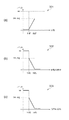
そこで、本実施形態では、目標PSNRと観測PSNRとの差分に応じて各検出部に与えられる閾値を制御することを特徴とする。図5は、横軸に目標PSNRから観測PSNRを引いた差分(PSNRの差分)、縦軸に各検出部の閾値を取ったグラフである。 Therefore, the present embodiment is characterized in that the threshold given to each detection unit is controlled according to the difference between the target PSNR and the observed PSNR. FIG. 5 is a graph in which the horizontal axis represents the difference obtained by subtracting the observed PSNR from the target PSNR (PSNR difference), and the vertical axis represents the threshold value of each detection unit.
図5(a)は、PSNRの差分に対する平坦検出用閾値202の変化の様子を表すグラフ501を示す。ここで横軸はPSNRの差分、縦軸は図3(a)の関数301におけるth1F、th2Fに対応する平坦検出用閾値である。即ち、閾値th1Fやth2Fは、PSNRの差分に応じてグラフ501に対応するように変化する。
FIG. 5A shows a
図5(b)はエッジ検出用閾値204の変化の様子を表すグラフ502を示す。ここで横軸はPSNRの差分、縦軸は図3の関数302におけるth1E、th2Eに対応するエッジ検出用閾値である。即ち、閾値th1Eやth2Eは、PSNRの差分に応じてグラフ502に対応するように変化する。
FIG. 5B shows a
図5(c)は肌色検出用閾値206の変化の様子を表すグラフ503を示す。ここで横軸はPSNRの差分、縦軸は図3の関数303におけるth1S、th2Sに対応する肌色検出用閾値である。即ち、閾値th1Sやth2Sは、PSNRの差分に応じてグラフ503に対応するように変化する。
FIG. 5C shows a
図4の領域401のように、PSNR算出部115で算出された観測PSNRが目標PSNRより高い場合、画質は安定しているがより高画質化を行える。そこで、エッジ部及び肌色部では、より多く検出するように閾値を変動させる。なお、閾値の変動は図5に示しているように目標PSNRと観測PSNRの離れ具合(劣化度合い)を考慮して連続的に変化させることが望ましい。また、平坦部に関しては量子化パラメータを変動させたとしても符号量が大きく増加することはないので閾値の変動は行わないようにする。
When the observed PSNR calculated by the
一方、図4の領域402のように、観測PSNRが目標PSNRより低く、劣化度合いが高い場合、全体的な画質が良くないためエッジのようなブロックに多くの符号量を与えても画質の向上は見込めない。そこで、エッジ部では検出閾値(Th1EとTh2E)を上げて強いエッジ、すなわち視覚的に特に目立つエッジのみを検出するようにする。また肌色部に対しては、人間の顔など重要領域が含まれることが多い。そこで、観測PSNRが目標PSNRより特に低く、劣化度合いが所定の度合いを超えて高い場合でも、閾値(Th1SとTh2S)を減少させて肌色部分を多く検出するようにする。この場合、顔以外の部分は劣化が起こっても、肌色部分の画質が向上することで全体的な視覚的印象は良くなる。
On the other hand, when the observed PSNR is lower than the target PSNR and the degree of deterioration is high as in the
なお、閾値の変動は図5に示しているように目標PSNRと観測PSNRの離れ具合を考慮して連続的に変化させることが望ましい。また、各検出部の方法はここで述べた方法に限ったものではなく、検出を行うための要素となる分散値は周波数変換などで代用可能である。 As shown in FIG. 5, it is desirable to change the threshold value continuously in consideration of the distance between the target PSNR and the observed PSNR. Further, the method of each detection unit is not limited to the method described here, and a dispersion value that is an element for performing detection can be substituted by frequency conversion or the like.
以上のように、本実施形態に対応する符号化装置によれば、符号化画像の劣化度合いに応じて抽出するブロック数を変化させることで、発生符号量が安定した状態で視覚的劣化の目立ちやすいブロックに対する画質向上を行うことが可能となる。また、符号化画像の劣化度合いが大きい場合でも、特に劣化を抑えたいブロックにより多くの符号量を与えるので画質が良いという印象を与えることができる。 As described above, according to the encoding apparatus corresponding to the present embodiment, the number of blocks to be extracted is changed according to the degree of deterioration of the encoded image, so that the visual deterioration is conspicuous in a state where the generated code amount is stable. It is possible to improve the image quality for easy blocks. Even when the degree of deterioration of the encoded image is large, it is possible to give an impression that the image quality is good because a larger amount of code is given to a block in which deterioration is particularly suppressed.
[第2の実施形態]
第1の実施形態は、特徴抽出部113において、各マクロブロックが視覚的劣化の目立ちやすいブロックであるか否かを判断する基準を画像の劣化度合いであるPSNRを用いていた。これに対して第2の実施形態では、再生時にフリッカが発生しそうな画像であるかに応じて各検出部に与えられる閾値を制御することを特徴とする。
[Second Embodiment]
In the first embodiment, the
図6は、第2の実施形態に対応する符号化装置の全体構成の一例を示すブロック図であり、基本的構成は図1と同じであるが、図1に対して、フリッカを検出するための機構が付加されている。なお、特徴抽出部613の構成は図1の特徴抽出部113と同じであるので図2を代用する。
FIG. 6 is a block diagram showing an example of the overall configuration of the encoding apparatus corresponding to the second embodiment. The basic configuration is the same as that in FIG. The mechanism is added. Note that since the configuration of the
図6において、フレーム並べ替え部601、加減算部602、直交変換(DCT)部603、量子化部604、逆量子化部605、逆直交変換(逆DCT)部606、動き予測・動き補償部607を含む。また、加減算部608、フレームメモリであるビデオバッファ609、可変長符号化部610、符号量制御部611、量子化制御部612、特徴抽出部613、本符号化装置からのストリームを一時的に保持するバッファ614を含む。更に、入力画像と局所復号画像からPSNR(Peak Signal to Noise Ratio)を算出するPSNR算出部615、本符号化装置からの出力信号116を含む。以上は図1と同じ構成である。それに加えて、フレーム特徴検出部620、フレーム動き検出部621、フリッカ検出部622を設けた。なお、特徴抽出部613はマクロブロック単位で特徴を抽出するのに対して、フレーム特徴検出部620はフレーム単位で特徴を検出するものであり表現を分けておく。これらの作用を説明する。
In FIG. 6, a
フレーム特徴検出部620は、フレームアクティビティとして、入力端子600からの画像データから今から符号化する画像の複雑度を算出する。第2の実施形態では、複雑度として、画像データの交流成分量、好ましくは高周波成分量を採用する。具体的には、1画面の画像データを所定サイズのブロックに分割し、各ブロックに対して分散を算出する。そして、各ブロックで算出した分散を画像の全ブロック数分加算した結果を、高周波成分量とする。なお、分散でなく、DCT(離散コサイン変換)やアダマール変換といった周波数変換を行い、その周波数成分で代用しても良い。
The frame
フレーム動き検出部621は、入力端子600からの画像データを隣接するフレーム間で相関をとり、今から符号化する画像全体がどれだけ動いたかを算出する。具体的には、1画面の画像を所定サイズのブロックに分割し、そのブロック毎に、隣接する画面間で一方の画像の座標をずらしながら相関が最も高くなる座標ずれ量を算出する。そして、各ブロックで算出した動きベクトル量の画面内の総和をフレーム間動き量とする。なお、このフレーム間動き量は、大局的な動き(グローバルベクトル)を示すものであり、ここで示す方法以外の方法でも算出できる。
The frame
また、第1の実施形態と同様に、入力画像と局所復号画像とから符号化歪み量を算出するためのPSNR算出部615が存在する。PSNR算出部615は、先ず、入力端子600からの画像データと局所復号画像データ(加減算部608の出力画像データ)とから、マクロブロック単位のPSNRを算出する。そして、PSNR算出部615は、マクロブロック毎のPSNRの画面内の総和を、最終的なPSNRとして出力する。ここで算出するPSNRは、符号化済みの画像に対するもの、即ち、今から符号化する画像に対して少なくとも1つ以上前に入力された画像に対するものである。
Similarly to the first embodiment, there is a
フリッカ検出部622には、フレーム特徴検出部620からのフレームアクティビティ、フレーム動き検出部621からのフレーム間動き量、及びPSNR算出部615からのPSNRが入力する。フリッカ検出部622は、これらの3つのパラメータ値に従い、今から符号化する画像にフリッカが発生しそうかどうかを検出する。
The
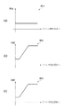
ここで、フリッカの発生のメカニズムについて図7を用いて以下に述べる。図7は、本実施形態に対応する、フリッカの発生のメカニズムを説明するための図であり、フレーム内符号化とフレーム間符号化を併用する符号化方式における符号化後の輝度信号を示す。図7のグラフ701は、Iピクチャの再生信号レベルの時間変化を示す。横軸は時間(又はフレーム)を示し、縦軸は、再生映像信号レベルを示す。輝度平均で示す点線は映像信号の平均値を示している。これはグラフ702、703も同様である。ピーク輝度で示す点線は映像信号の輝度のピーク値を示している。これはグラフ702、703も同様である。フラットな映像信号に重畳するノイズ成分のピーク輝度は、フレーム内符号化によりある程度、再構成可能である。これは、上述した符号量制御アルゴリズムで、Iピクチャに対する符号量割り当てが、他のピクチャタイプに比べて多いことに起因する。
Here, the mechanism of flicker generation will be described below with reference to FIG. FIG. 7 is a diagram for explaining a flicker generation mechanism corresponding to the present embodiment, and shows a luminance signal after encoding in an encoding method using both intraframe encoding and interframe encoding. A
図7のグラフ702は、Pピクチャ及びBピクチャのようなフレーム間符号化されたピクチャの再生信号レベルの時間変化を示す。横軸は時間(又はフレーム)を示し、縦軸は、再生映像信号レベルを示す。複雑度の高い画像はフレーム間の相関が低くなるので、通常の符号化ではPピクチャ及びBピクチャのフレーム間差分情報量が増加する。その結果、符号化による映像信号の劣化が生じ、輝度のピークを再構成できなくなる。グラフ702では、グラフ701に示すIピクチャに比べ、ピーク輝度に差が生じている。これにより、グラフ703に示すように、動画再生時に輝度フリッカが発生する。横軸は時間(又はフレーム)を示し、縦軸は、再生映像信号レベルを示す。
A
ただし、ピーク輝度差が大きいもの全てが、フリッカとして感じられるわけではない。人間の視覚特性は、動きの大きい画像の劣化よりも動きの小さい画像の劣化を検知しやすい。静止画で平坦部がざわざわしているのが気になるのはそのためである。そのため、動きの大きい画像ではピーク輝度差は検知できず、フリッカとして感じることが少ない。動きのある画像よりも動きの小さい画像でピーク輝度差が生じると、フリッカとして目立ってしまう。 However, not all that have a large difference in peak luminance are perceived as flicker. Human visual characteristics are more likely to detect degradation of images with less motion than degradation of images with greater motion. This is why the flat part of the still image is bothering. For this reason, the peak luminance difference cannot be detected in an image with a large motion, and it is less likely to feel flicker. If a difference in peak luminance occurs in an image that moves less than an image that moves, the image becomes noticeable as flicker.
以上がフリッカ発生のメカニズムである。フリッカが発生する条件として、符号化後の輝度ピーク値がピクチャタイプ毎に異なること、動きの少ない画像であることは上述した。符号化後の輝度ピーク値が生じる画像の条件は、1)画像の複雑さが高いこと、及び、2)符号化画像が劣化していることの二つの条件を満たしていることである。一つ目の条件は、フレーム特徴検出部620で算出した高周波成分量が高いことを意味する。二つ目の条件は、PSNR算出部615で算出したPSNRが低いことを意味する。
The above is the mechanism of flicker generation. As described above, the flicker generation condition is that the luminance peak value after encoding differs for each picture type and that the image has little motion. The condition of an image in which a luminance peak value after encoding is satisfied is that the following two conditions are satisfied: 1) the complexity of the image is high, and 2) the encoded image is deteriorated. The first condition means that the high-frequency component amount calculated by the frame
なお、どちらか一方の条件を満たしていなければ、輝度ピーク差が生じるとは言えない。例えば、高周波を多く含んだ画像は画像の複雑さが高く、一つ目の条件は満たす。しかし、ビットレートが高い場合には、符号化画像は劣化していないので輝度ピーク差は生じない。一方、符号化画像が劣化していると、二つ目の条件は満たす。しかし、ビットレートが低い場合、画像の複雑さが低くても符号化画像が劣化する。この場合、輝度ピーク差は生じない。動きの少ない画像の条件は、画像全体の動き量が小さいことであり、フレーム動き検出部621で算出したフレーム間動き量が少ないことを意味する。
Note that if either one of the conditions is not satisfied, it cannot be said that a luminance peak difference occurs. For example, an image containing a lot of high frequencies has a high image complexity and satisfies the first condition. However, when the bit rate is high, the encoded image is not deteriorated, so that there is no luminance peak difference. On the other hand, if the encoded image is degraded, the second condition is satisfied. However, when the bit rate is low, the encoded image deteriorates even if the complexity of the image is low. In this case, no luminance peak difference occurs. The condition for an image with little motion is that the amount of motion of the entire image is small, which means that the amount of motion between frames calculated by the
フリッカ検出部622は、高周波成分量、フレーム間動き量、PSNRの値からフリッカ発生度合いを算出することができる。高周波成分量がその基準値より高く、PSNRがその基準値より低く、フレーム動き量がその基準値より少ない場合、今から符号化しようとする画像でフリッカが発生する可能性が高いので、フリッカ発生度合いは高くなる。一方、その条件に合致しない場合、フリッカ発生度合いは低くなる。フリッカ発生度合いについて計算方法は問わないが、離散的な値であり、値が大きくなればフリッカ発生度合いが大きくなるものとする。
The
図8は、本実施形態に対応する、フリッカの発生度合いと検出閾値の関係を説明するための図である。図8は、横軸にフリッカ発生度合い、縦軸に各検出部の閾値を取ったグラフを示す。図8(a)は、フリッカ発生度合いに対する平坦検出用閾値202の変化の様子を表すグラフ801を示す。ここで横軸はフリッカ発生度合い、縦軸は図3の関数301におけるth1F、th2Fに対応する平坦検出用閾値である。即ち、閾値th1Fやth2Fは、フリッカの発生度合いに応じてグラフ501に対応するように変化する。
FIG. 8 is a diagram for explaining the relationship between the occurrence degree of flicker and the detection threshold corresponding to the present embodiment. FIG. 8 shows a graph in which the horizontal axis represents the flicker occurrence level and the vertical axis represents the threshold value of each detection unit. FIG. 8A shows a
図8(b)はフリッカ発生度合いに対するエッジ検出用閾値204の変化の様子を表すグラフ802を示す。ここで横軸はフリッカ発生度合い、縦軸は図3の関数302におけるth1E、th2Eに対応するエッジ検出用閾値である。即ち、閾値th1Eやth2Eは、フリッカの発生度合いに応じてグラフ502に対応するように変化する。
FIG. 8B shows a
図8(c)はフリッカ発生度合いに対する肌色検出用閾値206の変化の様子を表すグラフ803を示す。ここで横軸はフリッカ発生度合い、縦軸は図3の関数303におけるth1S、th2Sに対応する肌色検出用閾値である。即ち、閾値th1Sやth2Sは、フリッカの発生度合いに応じてグラフ503に対応するように変化する。
FIG. 8C shows a
フリッカ検出部622の検出結果から、フリッカ発生度合いが高い場合、劣化が目立つ領域に対して符号量を与え過ぎてしまうと、その反動で高周波成分を含む領域に対する符号量が少なくなってしまい、フリッカが強く発生してしまう。そこで、エッジ部では検出閾値(Th1EとTh2E)を上げて強いエッジ、すなわち視覚的に特に目立つエッジのみを検出するようにする。また肌色部では、検出閾値(Th1SとTh2S)を上げて強い肌色、すなわち視覚的に特に目立つ肌色のみを検出するようにする。
From the detection result of the
一方、フリッカ検出部622の検出結果から、フリッカ発生度合いが低い場合、画像に含まれる高周波成分が少なく、PSNRも十分高いため、劣化が目立つ領域に対して更に符号量を与えることが可能である。そこで、エッジ部では検出閾値(Th1EとTh2E)を下げてエッジを多く検出するようにする。また肌色部では、検出閾値(Th1SとTh2S)を下げて肌色を多く検出するようにする。なお平坦部に関しては、量子化パラメータを変動させたとしても符号量が大きく増加することはないのでフリッカの発生度合いによっては平坦閾値(Th1FとTh2F)を変化させない。
On the other hand, from the detection result of the
以上のように、本実施形態に対応する符号化装置によれば、符号化画像のフリッカの発生度合いに応じて抽出するブロック数を変化させることで、発生符号量が安定した状態で視覚的劣化の目立ちやすいブロックに対する画質向上を行うことが可能となる。また、符号化画像のフリッカの発生度合いが大きい場合でも、特に劣化を抑えたいブロックにより多くの符号量を与えるので画質が良いという印象を与えることができる。 As described above, according to the encoding device corresponding to the present embodiment, the number of blocks to be extracted is changed in accordance with the degree of occurrence of flicker in the encoded image, thereby visually degrading the generated code amount in a stable state. Therefore, it is possible to improve the image quality of a block that is easily noticeable. Further, even when the degree of flicker occurrence in the encoded image is large, it is possible to give an impression that the image quality is good because a larger amount of code is given to the block whose deterioration is to be suppressed.
[その他の実施形態]
本発明の目的は、前述した機能を実現するコンピュータプログラムのコードを記録した記憶媒体を、システムに供給し、そのシステムがコンピュータプログラムのコードを読み出し実行することによっても達成される。この場合、記憶媒体から読み出されたコンピュータプログラムのコード自体が前述した実施形態の機能を実現し、そのコンピュータプログラムのコードを記憶した記憶媒体は本発明を構成する。また、そのプログラムのコードの指示に基づき、コンピュータ上で稼働しているオペレーティングシステム(OS)などが実際の処理の一部または全部を行い、その処理によって前述した機能が実現される場合も含まれる。
[Other Embodiments]
The object of the present invention can also be achieved by supplying a storage medium storing a computer program code for realizing the above-described functions to the system, and the system reading and executing the computer program code. In this case, the computer program code itself read from the storage medium realizes the functions of the above-described embodiments, and the storage medium storing the computer program code constitutes the present invention. In addition, the operating system (OS) running on the computer performs part or all of the actual processing based on the code instruction of the program, and the above-described functions are realized by the processing. .
さらに、以下の形態で実現しても構わない。すなわち、記憶媒体から読み出されたコンピュータプログラムコードを、コンピュータに挿入された機能拡張カードやコンピュータに接続された機能拡張ユニットに備わるメモリに書込む。そして、そのコンピュータプログラムのコードの指示に基づき、その機能拡張カードや機能拡張ユニットに備わるCPUなどが実際の処理の一部または全部を行って、前述した機能が実現される場合も含まれる。 Furthermore, you may implement | achieve with the following forms. That is, the computer program code read from the storage medium is written into a memory provided in a function expansion card inserted into the computer or a function expansion unit connected to the computer. Then, based on the instruction of the code of the computer program, the above-described functions are realized by the CPU or the like provided in the function expansion card or function expansion unit performing part or all of the actual processing.
本発明を上記記憶媒体に適用する場合、その記憶媒体には、先に説明したフローチャートに対応するコンピュータプログラムのコードが格納されることになる。 When the present invention is applied to the above storage medium, the computer program code corresponding to the flowchart described above is stored in the storage medium.
100・・・入力部(入力信号)
101・・・フレーム並べ替え部
102・・・加減算部
103・・・直交変換部
104・・・量子化部
105・・・逆量子化部
106・・・逆直交変換部
107・・・動き予測・動き補償部
108・・・加減算部
109・・・ビデオバッファ(フレームメモリ)
110・・・可変長符号化部
111・・・符号量制御部
112・・・量子化制御部
113・・・特徴抽出部
114・・・バッファ
115・・・PSNR算出部
116・・・出力部(出力信号、ストリーム)
100: Input unit (input signal)
101 ...
110 ... variable
Claims (9)
前記複数のブロックのそれぞれについて画像の特徴を判定し、視覚的劣化が目立ちやすいブロックであるか否かを検出する検出手段と、
前記検出手段による検出結果に基づいて、前記ブロックごとの量子化パラメータを決定する決定手段と、
前記ブロックの直交変換と、決定された前記量子化パラメータを用いた量子化とを行う変換手段と、
前記変換手段による変換結果を、可変長符号化する符号化手段と、
前記変換手段による変換結果を逆変換して局所復号画像を生成する逆変換手段と、
前記画像の特徴を判定するための判定基準を変化させるための参照値を算出する算出手段と、
を備え、
前記算出手段は、前記入力画像と前記局所復号画像とに基づいてPSNRを演算し、演算された前記PSNRの値に基づく画像の劣化度合いを示す前記参照値を出力し、
前記検出手段は、
画像の特徴毎に設定された閾値を前記判定基準として用いて判定を行って前記視覚的劣化が目立ちやすいブロックを検出し、
前記閾値の値は画像の特徴毎に前記参照値がとりえる各値と対応づけて設定され、前記算出された参照値に応じた閾値が前記判定基準として用いられることを特徴とする符号化装置。 An encoding device for encoding an input image by dividing it into a plurality of blocks,
Detecting means for determining the characteristics of the image for each of the plurality of blocks, and detecting whether or not the visual deterioration is a conspicuous block;
Determining means for determining a quantization parameter for each block based on a detection result by the detecting means;
Transform means for performing orthogonal transform of the block and quantization using the determined quantization parameter;
Encoding means for variable-length encoding the conversion result by the conversion means;
Inverse transformation means for inversely transforming the transformation result by the transformation means to generate a local decoded image;
Calculating means for calculating a reference value for changing a determination criterion for determining the feature of the image;
With
The calculating means calculates a PSNR based on the input image and the locally decoded image, and outputs the reference value indicating a degree of image degradation based on the calculated PSNR value.
The detection means includes
Performing a determination using a threshold set for each feature of the image as the determination criterion to detect a block in which the visual deterioration is conspicuous,
The threshold value is set in association with each value that can be taken by the reference value for each feature of the image, and a threshold value corresponding to the calculated reference value is used as the determination criterion. .
前記検出手段は、前記ブロック内の画素の分散値を算出し、該分散値の大きさに基づいて、該ブロックが平坦部を構成するブロックであるかを判定して、前記視覚的劣化が目立ちやすいブロックの検出を行うことを特徴とする請求項1に記載の符号化装置。 When the block in which the visual deterioration is conspicuous is a block constituting a flat portion in the input image,
The detection means calculates a variance value of the pixels in the block, determines whether the block is a block constituting a flat portion based on the magnitude of the variance value, and the visual deterioration is conspicuous. The encoding apparatus according to claim 1 , wherein easy block detection is performed.
前記検出手段は、前記ブロックをサブブロックに更に分割して、該サブブロック間での画素の分散値の差分値を算出し、該差分値の大きさに基づいて、該ブロックがエッジを構成するブロックであるかを判定して、前記視覚的劣化が目立ちやすいブロックの検出を行うことを特徴とする請求項1に記載の符号化装置。 When the block in which the visual deterioration is conspicuous is a block constituting an edge in the input image,
The detection means further divides the block into sub-blocks, calculates a difference value of pixel dispersion values between the sub-blocks, and the block constitutes an edge based on the magnitude of the difference value to determine whether a block, the encoding apparatus according to claim 1, characterized in that the detection of the visual degradation is noticeable block.
前記参照値が示す度合いが予め定めた度合いよりも高くなる場合には、前記第2の閾値の値を増加させることを特徴とする請求項4に記載の符号化装置。 The detection means uses the second threshold as the determination criterion, determines whether the block is a block constituting an edge by comparing the second threshold and the difference value,
The encoding apparatus according to claim 4 , wherein when the degree indicated by the reference value is higher than a predetermined degree, the value of the second threshold value is increased.
前記検出手段は、前記ブロック内の肌色画素の個数を算出し、該個数の大きさに基づいて、該ブロックが肌色部分を構成するブロックであるかを判定して、前記視覚的劣化が目立ちやすいブロックの検出を行うことを特徴とする請求項1に記載の符号化装置。 When the block in which the visual deterioration is conspicuous is a block constituting a skin color part in the input image,
The detection means calculates the number of skin color pixels in the block, determines whether the block is a block constituting a skin color part based on the size of the number, and the visual deterioration is easily noticeable. The encoding apparatus according to claim 1 , wherein block detection is performed.
前記参照値が前記画像の劣化度合いを示す場合に、該劣化度合いが予め定めた度合いよりも高くなる場合には前記第3の閾値の値を減少させることを特徴とする請求項6に記載の符号化装置。 The detection means uses a third threshold value as the determination criterion, determines whether the block is a block constituting a skin color part by comparing the third threshold value and the number,
When the reference value indicating the degree of deterioration of the image, in a case where the deterioration degree is higher than the degree to which predetermined according to claim 6, characterized in that to reduce the value of the third threshold value Encoding device.
検出手段が、前記複数のブロックのそれぞれについて画像の特徴を判定し、視覚的劣化が目立ちやすいブロックであるか否かを検出する検出工程と、
決定手段が、前記検出工程における検出結果に基づいて、前記ブロックごとの量子化パラメータを決定する決定工程と、
変換手段が、前記ブロックの直交変換と、決定された前記量子化パラメータを用いた量子化とを行う変換工程と、
符号化手段が、前記変換工程における変換結果を、可変長符号化する符号化工程と、
逆変換手段が、前記変換工程における変換結果を逆変換して局所復号画像を生成する逆変換工程と、
算出手段が、前記画像の特徴を判定するための判定基準を変化させるための参照値を算出する算出工程と、
を備え、
前記算出工程では、前記入力画像と前記局所復号画像とに基づいてPSNRを演算し、演算された前記PSNRの値に基づく画像の劣化度合いを示す前記参照値を出力し、
前記検出工程では、
画像の特徴毎に設定された閾値を前記判定基準として用いて判定を行って前記視覚的劣化が目立ちやすいブロックを検出し、
前記閾値の値は画像の特徴毎に前記参照値がとりえる各値と対応づけて設定され、前記算出された参照値に応じた閾値が前記判定基準として用いられる
ことを特徴とする符号化装置の制御方法。 A method for controlling an encoding apparatus that divides an input image into a plurality of blocks and encodes the input image,
A detecting step of detecting a feature of the image for each of the plurality of blocks, and detecting whether or not the visual degradation is a conspicuous block;
A determination unit that determines a quantization parameter for each block based on a detection result in the detection step;
A transforming step in which transforming means performs orthogonal transform of the block and quantization using the determined quantization parameter;
An encoding step, wherein the encoding means performs variable length encoding on the conversion result in the conversion step;
An inverse transforming step in which an inverse transforming unit reversely transforms the transform result in the transforming step to generate a local decoded image;
A calculating step for calculating a reference value for changing a determination criterion for determining the feature of the image;
With
In the calculating step, a PSNR is calculated based on the input image and the local decoded image, and the reference value indicating a degree of image degradation based on the calculated PSNR value is output.
In the detection step,
Performing a determination using a threshold set for each feature of the image as the determination criterion to detect a block in which the visual deterioration is conspicuous,
The threshold value is set in association with each value that can be taken by the reference value for each feature of the image, and a threshold value corresponding to the calculated reference value is used as the determination criterion. Control method for encoding apparatus.
Priority Applications (4)
| Application Number | Priority Date | Filing Date | Title |
|---|---|---|---|
| JP2008266831A JP5078837B2 (en) | 2007-10-29 | 2008-10-15 | Encoding apparatus, encoding apparatus control method, and computer program |
| US12/256,971 US8363719B2 (en) | 2007-10-29 | 2008-10-23 | Encoding apparatus, method of controlling thereof, and computer program |
| CN2008101735122A CN101426135B (en) | 2007-10-29 | 2008-10-29 | Encoding apparatus, method of controlling thereof |
| US13/736,418 US9241159B2 (en) | 2007-10-29 | 2013-01-08 | Encoding apparatus, method of controlling thereof, and computer program |
Applications Claiming Priority (3)
| Application Number | Priority Date | Filing Date | Title |
|---|---|---|---|
| JP2007280940 | 2007-10-29 | ||
| JP2007280940 | 2007-10-29 | ||
| JP2008266831A JP5078837B2 (en) | 2007-10-29 | 2008-10-15 | Encoding apparatus, encoding apparatus control method, and computer program |
Publications (3)
| Publication Number | Publication Date |
|---|---|
| JP2009135902A JP2009135902A (en) | 2009-06-18 |
| JP2009135902A5 JP2009135902A5 (en) | 2011-04-07 |
| JP5078837B2 true JP5078837B2 (en) | 2012-11-21 |
Family
ID=40616427
Family Applications (1)
| Application Number | Title | Priority Date | Filing Date |
|---|---|---|---|
| JP2008266831A Expired - Fee Related JP5078837B2 (en) | 2007-10-29 | 2008-10-15 | Encoding apparatus, encoding apparatus control method, and computer program |
Country Status (2)
| Country | Link |
|---|---|
| JP (1) | JP5078837B2 (en) |
| CN (1) | CN101426135B (en) |
Families Citing this family (6)
| Publication number | Priority date | Publication date | Assignee | Title |
|---|---|---|---|---|
| JP5618128B2 (en) * | 2010-02-22 | 2014-11-05 | ソニー株式会社 | Encoding apparatus, encoding method, and program |
| US8559736B2 (en) | 2010-03-24 | 2013-10-15 | Panasonic Corporation | Image decoding apparatus, image coding apparatus, image decoding circuit, and image decoding method |
| JP6226578B2 (en) | 2013-06-13 | 2017-11-08 | キヤノン株式会社 | Image coding apparatus, image coding method, and program |
| WO2014199566A1 (en) | 2013-06-13 | 2014-12-18 | 日本電気株式会社 | Video encoding device, video encoding method, and program-containing non-transitory computer-readable medium |
| JP5901667B2 (en) * | 2014-02-10 | 2016-04-13 | オリンパス株式会社 | Image processing apparatus and method, image processing program, and imaging apparatus |
| US9930346B2 (en) * | 2014-04-15 | 2018-03-27 | Qualcomm Incorporated | System and method for flatness detection for display stream compression (DSC) |
Family Cites Families (8)
| Publication number | Priority date | Publication date | Assignee | Title |
|---|---|---|---|---|
| JP2664223B2 (en) * | 1988-10-14 | 1997-10-15 | 日本電信電話株式会社 | Orthogonal transform coefficient quantization circuit |
| JP2002185966A (en) * | 2000-12-15 | 2002-06-28 | Matsushita Electric Ind Co Ltd | Video encoder |
| JP2002238060A (en) * | 2001-02-07 | 2002-08-23 | Sony Corp | Image-coding method, image coder, program and recording medium |
| JP2004297768A (en) * | 2003-03-10 | 2004-10-21 | Mitsubishi Electric Corp | Video signal encoding apparatus, and video signal encoding method |
| US20070139564A1 (en) * | 2004-02-27 | 2007-06-21 | Koninklijke Philips Electronics N.V. | System and method for global indication of mpeg impairments in compressed digital video |
| JP4243218B2 (en) * | 2004-05-11 | 2009-03-25 | 日本放送協会 | Quantization control device, method and program thereof, and adaptive quantization encoding device |
| JP2006262075A (en) * | 2005-03-17 | 2006-09-28 | Pioneer Electronic Corp | Image encoder, method for encoding image and program for encoding image |
| JP4246723B2 (en) * | 2005-08-29 | 2009-04-02 | 日本電信電話株式会社 | Intraframe predictive coding control method, intraframe predictive coding control apparatus, intraframe predictive coding control program, and computer-readable recording medium storing the program |
-
2008
- 2008-10-15 JP JP2008266831A patent/JP5078837B2/en not_active Expired - Fee Related
- 2008-10-29 CN CN2008101735122A patent/CN101426135B/en not_active Expired - Fee Related
Also Published As
| Publication number | Publication date |
|---|---|
| CN101426135B (en) | 2011-07-20 |
| JP2009135902A (en) | 2009-06-18 |
| CN101426135A (en) | 2009-05-06 |
Similar Documents
| Publication | Publication Date | Title |
|---|---|---|
| US9241159B2 (en) | Encoding apparatus, method of controlling thereof, and computer program | |
| JP5269593B2 (en) | Encoding device, encoding method, decoding device, decoding method, and program thereof | |
| JP5054826B2 (en) | Coding mode determination method and apparatus using spatio-temporal complexity | |
| US8000393B2 (en) | Video encoding apparatus and video encoding method | |
| JP4804107B2 (en) | Image encoding apparatus, image encoding method and program thereof | |
| JP5078837B2 (en) | Encoding apparatus, encoding apparatus control method, and computer program | |
| US11012698B2 (en) | Image encoding apparatus and method for controlling the same | |
| KR20130108948A (en) | Image encoding method using adaptive preprocessing | |
| US20170374361A1 (en) | Method and System Of Controlling A Video Content System | |
| JP5618128B2 (en) | Encoding apparatus, encoding method, and program | |
| JP4485996B2 (en) | Image encoding apparatus and image encoding program | |
| JP4736619B2 (en) | Image processing apparatus and image processing method | |
| JP4942208B2 (en) | Encoder | |
| JP5111128B2 (en) | Encoding apparatus, encoding apparatus control method, and computer program | |
| JP2007124580A (en) | Moving picture encoding program, program storage medium and encoder | |
| JP4936557B2 (en) | Encoder | |
| JP5295089B2 (en) | Image encoding device | |
| JP4857243B2 (en) | Image encoding apparatus, control method therefor, and computer program | |
| JP4186543B2 (en) | Encoding apparatus, encoding method, program, and recording medium | |
| JP5585271B2 (en) | Video encoding device | |
| KR20170077621A (en) | Method and Apparatus of removal of Flickering artifact for Video compression | |
| JP5006763B2 (en) | Image encoding apparatus, control method therefor, and computer program | |
| JP2007300557A (en) | Image encoding device and image encoding method | |
| JP4186544B2 (en) | Encoding apparatus, encoding method, program, and recording medium | |
| JP2012182831A (en) | Image encoder and control method thereof and computer program |
Legal Events
| Date | Code | Title | Description |
|---|---|---|---|
| A521 | Written amendment |
Free format text: JAPANESE INTERMEDIATE CODE: A523 Effective date: 20110217 |
|
| A621 | Written request for application examination |
Free format text: JAPANESE INTERMEDIATE CODE: A621 Effective date: 20110217 |
|
| A977 | Report on retrieval |
Free format text: JAPANESE INTERMEDIATE CODE: A971007 Effective date: 20120125 |
|
| A131 | Notification of reasons for refusal |
Free format text: JAPANESE INTERMEDIATE CODE: A131 Effective date: 20120220 |
|
| A521 | Written amendment |
Free format text: JAPANESE INTERMEDIATE CODE: A523 Effective date: 20120420 |
|
| TRDD | Decision of grant or rejection written | ||
| A01 | Written decision to grant a patent or to grant a registration (utility model) |
Free format text: JAPANESE INTERMEDIATE CODE: A01 Effective date: 20120730 |
|
| A01 | Written decision to grant a patent or to grant a registration (utility model) |
Free format text: JAPANESE INTERMEDIATE CODE: A01 |
|
| A61 | First payment of annual fees (during grant procedure) |
Free format text: JAPANESE INTERMEDIATE CODE: A61 Effective date: 20120828 |
|
| FPAY | Renewal fee payment (event date is renewal date of database) |
Free format text: PAYMENT UNTIL: 20150907 Year of fee payment: 3 |
|
| R151 | Written notification of patent or utility model registration |
Ref document number: 5078837 Country of ref document: JP Free format text: JAPANESE INTERMEDIATE CODE: R151 |
|
| FPAY | Renewal fee payment (event date is renewal date of database) |
Free format text: PAYMENT UNTIL: 20150907 Year of fee payment: 3 |
|
| LAPS | Cancellation because of no payment of annual fees |