JP4804107B2 - Image encoding apparatus, image encoding method and program thereof - Google Patents
Image encoding apparatus, image encoding method and program thereof Download PDFInfo
- Publication number
- JP4804107B2 JP4804107B2 JP2005310070A JP2005310070A JP4804107B2 JP 4804107 B2 JP4804107 B2 JP 4804107B2 JP 2005310070 A JP2005310070 A JP 2005310070A JP 2005310070 A JP2005310070 A JP 2005310070A JP 4804107 B2 JP4804107 B2 JP 4804107B2
- Authority
- JP
- Japan
- Prior art keywords
- edge
- block
- blocks
- encoding
- encoded
- Prior art date
- Legal status (The legal status is an assumption and is not a legal conclusion. Google has not performed a legal analysis and makes no representation as to the accuracy of the status listed.)
- Expired - Fee Related
Links
Images


Classifications
-
- H—ELECTRICITY
- H04—ELECTRIC COMMUNICATION TECHNIQUE
- H04N—PICTORIAL COMMUNICATION, e.g. TELEVISION
- H04N19/00—Methods or arrangements for coding, decoding, compressing or decompressing digital video signals
- H04N19/48—Methods or arrangements for coding, decoding, compressing or decompressing digital video signals using compressed domain processing techniques other than decoding, e.g. modification of transform coefficients, variable length coding [VLC] data or run-length data
-
- H—ELECTRICITY
- H04—ELECTRIC COMMUNICATION TECHNIQUE
- H04N—PICTORIAL COMMUNICATION, e.g. TELEVISION
- H04N19/00—Methods or arrangements for coding, decoding, compressing or decompressing digital video signals
- H04N19/10—Methods or arrangements for coding, decoding, compressing or decompressing digital video signals using adaptive coding
- H04N19/102—Methods or arrangements for coding, decoding, compressing or decompressing digital video signals using adaptive coding characterised by the element, parameter or selection affected or controlled by the adaptive coding
- H04N19/124—Quantisation
-
- H—ELECTRICITY
- H04—ELECTRIC COMMUNICATION TECHNIQUE
- H04N—PICTORIAL COMMUNICATION, e.g. TELEVISION
- H04N19/00—Methods or arrangements for coding, decoding, compressing or decompressing digital video signals
- H04N19/10—Methods or arrangements for coding, decoding, compressing or decompressing digital video signals using adaptive coding
- H04N19/134—Methods or arrangements for coding, decoding, compressing or decompressing digital video signals using adaptive coding characterised by the element, parameter or criterion affecting or controlling the adaptive coding
- H04N19/136—Incoming video signal characteristics or properties
- H04N19/14—Coding unit complexity, e.g. amount of activity or edge presence estimation
-
- H—ELECTRICITY
- H04—ELECTRIC COMMUNICATION TECHNIQUE
- H04N—PICTORIAL COMMUNICATION, e.g. TELEVISION
- H04N19/00—Methods or arrangements for coding, decoding, compressing or decompressing digital video signals
- H04N19/10—Methods or arrangements for coding, decoding, compressing or decompressing digital video signals using adaptive coding
- H04N19/134—Methods or arrangements for coding, decoding, compressing or decompressing digital video signals using adaptive coding characterised by the element, parameter or criterion affecting or controlling the adaptive coding
- H04N19/146—Data rate or code amount at the encoder output
- H04N19/15—Data rate or code amount at the encoder output by monitoring actual compressed data size at the memory before deciding storage at the transmission buffer
-
- H—ELECTRICITY
- H04—ELECTRIC COMMUNICATION TECHNIQUE
- H04N—PICTORIAL COMMUNICATION, e.g. TELEVISION
- H04N19/00—Methods or arrangements for coding, decoding, compressing or decompressing digital video signals
- H04N19/10—Methods or arrangements for coding, decoding, compressing or decompressing digital video signals using adaptive coding
- H04N19/134—Methods or arrangements for coding, decoding, compressing or decompressing digital video signals using adaptive coding characterised by the element, parameter or criterion affecting or controlling the adaptive coding
- H04N19/146—Data rate or code amount at the encoder output
- H04N19/152—Data rate or code amount at the encoder output by measuring the fullness of the transmission buffer
-
- H—ELECTRICITY
- H04—ELECTRIC COMMUNICATION TECHNIQUE
- H04N—PICTORIAL COMMUNICATION, e.g. TELEVISION
- H04N19/00—Methods or arrangements for coding, decoding, compressing or decompressing digital video signals
- H04N19/10—Methods or arrangements for coding, decoding, compressing or decompressing digital video signals using adaptive coding
- H04N19/169—Methods or arrangements for coding, decoding, compressing or decompressing digital video signals using adaptive coding characterised by the coding unit, i.e. the structural portion or semantic portion of the video signal being the object or the subject of the adaptive coding
- H04N19/17—Methods or arrangements for coding, decoding, compressing or decompressing digital video signals using adaptive coding characterised by the coding unit, i.e. the structural portion or semantic portion of the video signal being the object or the subject of the adaptive coding the unit being an image region, e.g. an object
- H04N19/176—Methods or arrangements for coding, decoding, compressing or decompressing digital video signals using adaptive coding characterised by the coding unit, i.e. the structural portion or semantic portion of the video signal being the object or the subject of the adaptive coding the unit being an image region, e.g. an object the region being a block, e.g. a macroblock
-
- H—ELECTRICITY
- H04—ELECTRIC COMMUNICATION TECHNIQUE
- H04N—PICTORIAL COMMUNICATION, e.g. TELEVISION
- H04N19/00—Methods or arrangements for coding, decoding, compressing or decompressing digital video signals
- H04N19/60—Methods or arrangements for coding, decoding, compressing or decompressing digital video signals using transform coding
- H04N19/61—Methods or arrangements for coding, decoding, compressing or decompressing digital video signals using transform coding in combination with predictive coding
Description
本発明は動画像データを圧縮符号化する画像符号化装置、画像符号化方法及びそのプログラムに関するものである。 The present invention relates to an image encoding apparatus, an image encoding method, and a program for compressing and encoding moving image data.
現在、数多くの製品で採用されているMPEG(Moving Pictures of Experts Group)圧縮は、DCT(Discrete Cosign Transformation)、量子化、可変長符号化の各処理と、前方向の動き補償フレーム間予測及び双方向の動き補償フレーム間予測を組み合わせた符号化方式である。MPEGは通常15枚のフレームデータをグループ化したGOP(Group Of Pictures)構造を採用する。GOPは、Iピクチャ(Intra−coded picture)、Pピクチャ(Predictive−coded picture)およびBピクチャ(Bidirectionally predictive−coded picture)で構成される。Iピクチャは画面内の情報のみで符号化され、PピクチャはIまたは他のPピクチャから前方向の予測を行うことで符号化され、BピクチャはI又はPピクチャから双方向の予測を行うことによって符号化されるビデオデータである。 Currently, MPEG (Moving Pictures of Experts Group) compression adopted in many products is DCT (Discrete Coordinate Transformation), quantization, variable-length encoding processing, forward motion compensation interframe prediction and both This is a coding scheme that combines motion compensation inter-frame prediction. MPEG normally employs a GOP (Group Of Pictures) structure in which 15 pieces of frame data are grouped. The GOP includes an I picture (Intra-coded picture), a P picture (Predictive-coded picture), and a B picture (Bidirectionally predictive-coded picture). The I picture is encoded only with information in the screen, the P picture is encoded by performing forward prediction from the I or other P pictures, and the B picture is bidirectionally predicted from the I or P picture Is video data encoded by.
MPEGに対応する画像符号化装置は、入力された信号を所定の画素数に分割したブロック、所謂DCTブロックに2次元直交変換を行うDCT変換回路と、変換後のDCT係数を量子化する量子化回路と、出力バッファ、所謂VBVバッファを考慮して量子化スケールコードを適当な値に制御するレート制御部とを備えて構成される。 An MPEG image encoding apparatus includes a block obtained by dividing an input signal into a predetermined number of pixels, a DCT conversion circuit that performs two-dimensional orthogonal transformation on a so-called DCT block, and a quantization that quantizes the DCT coefficients after conversion A circuit and a rate control unit that controls the quantization scale code to an appropriate value in consideration of an output buffer, a so-called VBV buffer.
例えば、図4に示すように、MPEG2に対応する画像符号化装置400は、CCD401で撮像された映像信号を保持し、かつ画面の並び替えを行うためのフレームバッファ402、フレームバッファ402から入力された映像信号とローカルデコード画像を表わす信号との差分を演算する減算回路413を備える。さらに、DCT回路403、量子化回路404、可変長符号化回路409、逆量子化回路405、IDCT回路406、動き推定回路407、動き補償回路408、記録媒体410、レート制御を行うコントローラ411、及びアクティビティ算出回路412を備える。
For example, as shown in FIG. 4, an
IピクチャおよびPピクチャの場合は、動き推定回路407、動き補償回路408において参照画面として使用されるため、量子化回路404の出力は、逆量子化回路405にも入力され、逆量子化された後にIDCT回路406において逆DCTが行われる。IDCT回路406の出力は、動き補償回路408に入力されて順次処理される。動き推定回路407、動き補償回路408は、前方向予測、後方向予測および両方向予測を行い、ローカルデコードされた信号を減算回路413に出力する。
In the case of an I picture and a P picture, since they are used as reference screens in the
減算回路413は、フレームバッファ402の出力と動き補償回路408の出力との間で減算処理を行い、差分値を演算する回路である。なお、入力されるのが画面内符号化されるIピクチャの場合は、減算回路413で減算処理を行わず、単にフレームバッファ402から映像信号が通過する。
The
Iピクチャ或いは差分値で表わされるP,Bピクチャは、DCT回路403でDCTされ、量子化回路404で量子化され、可変長符号化回路409で可変長符号化された後、記録媒体410に記録される。
The P picture and the B picture represented by the I picture or the difference value are DCTed by the
一方、量子化回路404で使用する量子化スケールコードは、コントローラ411で算出された量子化スケールコードの基準値と量子化の単位であるマクロブロックの視覚特性を反映させたアクティビティを用いることで決定される。その決定方法は以下の3ステップで構成される。
On the other hand, the quantization scale code used in the
第1ステップでは、GOP内の各ピクチャに対する割り当てビット量を、割り当て対象ピクチャを含めGOP内でまだ符号化されていないピクチャに対して割り当てられるビット量を基にして配分する。この配分をGOP内の符号化ピクチャ順に繰り返し、ピクチャごとにピクチャ目標ビット量を設定する。 In the first step, the allocated bit amount for each picture in the GOP is distributed based on the bit amount allocated to a picture that has not been encoded in the GOP including the allocation target picture. This distribution is repeated in the order of the encoded pictures in the GOP, and a picture target bit amount is set for each picture.
第2ステップでは、マクロブロック単位に量子化スケールの基準値を設定する。つまり、第2ステップでは、第1ステップで求められた各ピクチャに対する割り当てビット量と実際の発生ビット量とを一致させるため、可変長符号化回路409から得られる仮想バッファの容量(VBVバッファ容量)の情報を基に、量子化スケールの基準値をマクロブロック単位のフィードバック制御で求める。 In the second step, a quantization scale reference value is set for each macroblock. That is, in the second step, the capacity of the virtual buffer obtained from the variable length coding circuit 409 (VBV buffer capacity) in order to match the allocated bit amount for each picture obtained in the first step with the actual generated bit amount. Based on this information, the reference value of the quantization scale is obtained by feedback control in units of macroblocks.
第3ステップは、視覚特性を反映させるべく、マクロブロック単位でマクロブロックのアクティビティに基づいて量子化スケール値を補正する。フレーム目標ビット量を維持しつつ、アクティビティが低いマクロブロックでは量子化スケールを基準値より小さく補正し、アクティビティが高いマクロブロックでは量子化スケールを基準値より大きく補正する。このように視覚特性、特にアクティビティを考慮した適応量子化が行われる。 In the third step, the quantization scale value is corrected based on the activity of the macroblock for each macroblock to reflect the visual characteristics. While maintaining the frame target bit amount, the quantization scale is corrected to be smaller than the reference value in the macroblock having low activity, and the quantization scale is corrected to be larger than the reference value in the macroblock having high activity. In this way, adaptive quantization is performed in consideration of visual characteristics, particularly activity.
このようなMPEGの基礎技術については、例えば、「総合マルチメディア選書MPEG」(オーム社)ならびに「ディジタル放送・インターネットのための情報圧縮技術」(共立出版社)に開示されている。また、アクティビティを算出して、レート制御に適用する技術を開示した特許文献も存在する(例えば、特許文献1参照。)。
ところで、上記したMPEG2や、新たに標準化されたMPEG4−AVC(H.264とも称す)の符号化処理において、量子化はマクロブロック単位で行い、DCTはDCTブロック単位で処理を行うことが規定されている。また、量子化スケールコードは1つのマクロブロックに対して1つだけ決定されるため、MPEGの場合は、1つのマクロブロックに含まれる6つのDCTブロック(4つの輝度成分と2つの色差成分)に対して同じ量子化スケールコードで量子化を行うことになる。そのため、1つのマクロブロックを構成するDCTブロックのうち、エッジが含まれるDCTブロックとエッジが含まれないDCTブロックが混在した場合は、両者の電力分布が異なるのに対して同じ量子化スケールコードで量子化を行うことになる。このことは視覚特性の面から見ると決して好ましいとは言えない。 By the way, in the above-described MPEG2 and newly standardized MPEG4-AVC (also referred to as H.264) encoding processing, it is specified that quantization is performed in units of macroblocks and DCT is processed in units of DCT blocks. ing. In addition, since only one quantization scale code is determined for one macroblock, in the case of MPEG, there are six DCT blocks (four luminance components and two color difference components) included in one macroblock. On the other hand, quantization is performed with the same quantization scale code. Therefore, when a DCT block that includes an edge and a DCT block that does not include an edge are mixed among DCT blocks that constitute one macroblock, the power distribution of the two is different, but the same quantization scale code is used. Quantization will be performed. This is not preferable from the viewpoint of visual characteristics.
そのため、エッジが含まれるDCTブロックの量子化スケールコードを小さく設定すべきであるが、マクロブロック単位でエッジ情報を算出した場合、エッジのある領域が小さいとエッジ情報がマクロブロックの大きさに対して弱く検出されてしまい、結果としてマクロブロック内にエッジが存在しないと判断されてしまう可能性がある。また、マクロブロックを単位とすると、ノイズ成分をエッジとして誤検出してしまうことも考えられる。その際、誤検出されたノイズ成分では通常大きな信号差がないので、エッジ強度が低いとみなされ、量子化スケールコードは高い値に設定され、エッジを含むDCTブロックの劣化が生じてしまう。そのため、結果としてDCTブロックの劣化がマクロブロックの劣化として現れ画質の低下を招くことになる。 For this reason, the quantization scale code of the DCT block including the edge should be set small. However, when the edge information is calculated in units of macroblocks, if the edge area is small, the edge information is smaller than the macroblock size. As a result, it may be determined that there is no edge in the macroblock. In addition, when a macroblock is used as a unit, a noise component may be erroneously detected as an edge. At that time, since there is usually no large signal difference in the erroneously detected noise component, the edge strength is regarded as low, the quantization scale code is set to a high value, and degradation of the DCT block including the edge occurs. Therefore, as a result, the deterioration of the DCT block appears as the deterioration of the macroblock, and the image quality is lowered.
本発明は前述の如き問題点を解決し、動画像の符号化処理においてエッジを含むブロックの画質劣化を防ぐことができる画像符号化装置、画像符号化方法及びそのプログラムを提供することを目的とする。 An object of the present invention is to solve the above-described problems and to provide an image encoding device, an image encoding method, and a program thereof that can prevent image quality deterioration of blocks including edges in moving image encoding processing. To do.
上記課題を解決するために、本発明の画像符号化装置は、画像に含まれる画素配列を複数の第1のブロックに分割して、前記第1のブロック単位で量子化を含む符号化処理を行う符号化手段と、符号化対象の第1のブロックを更に複数に分割して得られる第2のブロックに含まれるエッジを検出するエッジ検出手段と、前記エッジ検出手段により前記第2のブロックにエッジが検出された場合に、検出されたエッジについてエッジ強度を算出し、前記符号化対象の第1のブロック内の複数の前記第2のブロックの中で算出されたエッジ強度が最大となるものを決定する算出手段と、前記算出手段により決定された最大のエッジ強度に基づいて、前記符号化手段に対して前記符号化対象の第1のブロックの量子化スケールを設定するための制御情報を出力する符号化制御手段とを備え、前記算出手段は、前記検出されたエッジの方向をさらに算出し、前記符号化対象の第1のブロック内で隣接する複数の前記第2のブロックにおいてそれぞれ算出された複数のエッジの方向が同じである場合に、前記決定された最大のエッジ強度に所定の値を付加して重みづけすることを特徴とする。
また、本発明の画像符号化装置は、画像に含まれる画素配列を複数の第1のブロックに分割して、前記第1のブロック単位で量子化を含む符号化処理を行う符号化手段と、符号化対象の第1のブロックを更に複数に分割して得られる第2のブロックに含まれるエッジを検出するエッジ検出手段と、前記エッジ検出手段により前記第2のブロックにエッジが検出された場合に、検出されたエッジについてエッジ強度を算出し、前記符号化対象の第1のブロック内の複数の前記第2のブロックの中で算出されたエッジ強度が最大となるものを決定する算出手段と、前記算出手段により決定された最大のエッジ強度に基づいて、前記符号化手段に対して前記符号化対象の第1のブロックの量子化スケールを設定するための制御情報を出力する符号化制御手段とを備え、前記算出手段は、前記検出されたエッジの方向をさらに算出し、前記符号化対象の第1のブロックに隣接する他の第1のブロックとの境界を跨いで隣接する複数の前記第2のブロックにおいてそれぞれ算出された複数のエッジの方向が同じである場合に、前記決定された最大のエッジ強度に所定の値を付加して重みづけすることを特徴とする。
In order to solve the above problems, an image encoding apparatus according to the present invention divides a pixel array included in an image into a plurality of first blocks, and performs an encoding process including quantization in units of the first blocks. Encoding means for performing, edge detecting means for detecting an edge included in a second block obtained by further dividing the first block to be encoded into a plurality of blocks, and the second block by the edge detecting means When an edge is detected, the edge strength is calculated for the detected edge, and the edge strength calculated among the plurality of second blocks in the first block to be encoded is maximized. And a control unit for setting the quantization scale of the first block to be encoded to the encoding unit based on the maximum edge strength determined by the calculation unit. And a coding control means for outputting a broadcast, said calculating means further calculates a direction of the detected edge, a plurality of the second blocks adjacent in the first block of the encoding target When the calculated directions of the plurality of edges are the same, a predetermined value is added to the determined maximum edge strength and weighted .
The image encoding apparatus of the present invention includes an encoding unit that divides a pixel array included in an image into a plurality of first blocks and performs an encoding process including quantization in units of the first blocks; Edge detection means for detecting an edge included in a second block obtained by further dividing the first block to be encoded into a plurality of parts, and an edge detected in the second block by the edge detection means And calculating means for calculating an edge strength for the detected edge and determining a maximum edge strength calculated among the plurality of second blocks in the first block to be encoded. Coding for outputting control information for setting a quantization scale of the first block to be coded to the coding means based on the maximum edge strength determined by the calculating means Control means, and the calculation means further calculates a direction of the detected edge, and a plurality of adjacent edges across a boundary with another first block adjacent to the first block to be encoded. When a plurality of edges calculated in the second block have the same direction, a predetermined value is added to the determined maximum edge strength and weighted.
また、本発明の画像符号化方法は、符号化手段が、画像に含まれる画素配列を複数の第1のブロックに分割して、前記第1のブロック単位で量子化を含む符号化処理を行う符号化ステップと、エッジ検出手段が、符号化対象の第1のブロックを更に複数に分割して得られる第2のブロックに含まれるエッジを検出するエッジ検出ステップと、算出手段が、前記エッジ検出ステップで前記第2のブロックにエッジが検出された場合に、検出されたエッジについてエッジ強度を算出し、前記符号化対象の第1のブロック内の複数の前記第2のブロックの中で算出されたエッジ強度が最大となるものを決定する算出ステップと、符号化制御手段が、前記算出ステップで決定された最大のエッジ強度に基づいて、前記符号化対象の第1のブロックの量子化スケールを設定する符号化制御ステップとを有し、前記算出ステップでは、前記検出されたエッジの方向をさらに算出し、前記符号化対象の第1のブロック内で隣接する複数の前記第2のブロックにおいてそれぞれ算出された複数のエッジの方向が同じである場合に、前記決定された最大のエッジ強度に所定の値を付加して重みづけすることを特徴とする。 In the image encoding method of the present invention, the encoding means divides a pixel array included in an image into a plurality of first blocks, and performs an encoding process including quantization in units of the first blocks. An encoding step; an edge detecting means for detecting an edge included in a second block obtained by further dividing the first block to be encoded into a plurality of blocks; and a calculating means for detecting the edge detection When an edge is detected in the second block in the step, an edge strength is calculated for the detected edge, and is calculated among the plurality of second blocks in the first block to be encoded. A calculation step for determining the one having the maximum edge strength, and an amount of the first block to be encoded based on the maximum edge strength determined by the encoding control means in the calculation step. Scale possess an encoding control step of setting, said at calculation step further calculates a direction of the detected edge, a plurality of the second adjacent in the first block of the encoding target When the directions of a plurality of edges respectively calculated in the block are the same, a predetermined value is added to the determined maximum edge strength and weighted .
さらに、本発明のプログラムは、符号化手段が、画像に含まれる画素配列を複数の第1のブロックに分割して、前記第1のブロック単位で量子化を含む符号化処理を行う符号化ステップと、エッジ検出手段が、符号化対象の第1のブロックを更に複数に分割して得られる第2のブロックに含まれるエッジを検出するエッジ検出ステップと、算出手段が、前記エッジ検出ステップで前記第2のブロックにエッジが検出された場合に、検出されたエッジについてエッジ強度を算出し、前記符号化対象の第1のブロック内の複数の前記第2のブロックの中で算出されたエッジ強度が最大となるものを決定する算出ステップと、符号化制御手段が、前記算出ステップで決定された最大のエッジ強度に基づいて、前記符号化対象の第1のブロックの量子化スケールを設定する符号化制御ステップとを有し、前記算出ステップでは、前記検出されたエッジの方向をさらに算出し、前記符号化対象の第1のブロック内で隣接する複数の前記第2のブロックにおいてそれぞれ算出された複数のエッジの方向が同じである場合に、前記決定された最大のエッジ強度に所定の値を付加して重みづけする画像符号化方法をコンピュータに実行させることを特徴とする。 Further, according to the program of the present invention, the encoding unit divides the pixel array included in the image into a plurality of first blocks and performs an encoding process including quantization in units of the first blocks. And an edge detecting step for detecting an edge included in a second block obtained by further dividing the first block to be encoded into a plurality of blocks, and a calculating unit in the edge detecting step When an edge is detected in the second block, an edge strength is calculated for the detected edge, and the edge strength is calculated among the plurality of second blocks in the first block to be encoded. A calculation step for determining the one having the maximum value, and the encoding control means, based on the maximum edge strength determined in the calculation step, the quantum of the first block to be encoded Possess an encoding control step of setting a scale, the at calculating step, the detected further to calculate the direction of the edge, a plurality of the second blocks adjacent the first block of the encoding target When the directions of a plurality of edges respectively calculated in step 1 are the same, a computer is caused to execute an image encoding method for adding a predetermined value to the determined maximum edge strength and weighting the image. .
本発明による画像符号化装置、画像符号化方法及びそのプログラムは、動画像の符号化処理においてエッジを含むブロックの画質劣化を防ぐことができる。 The image encoding apparatus, the image encoding method, and the program thereof according to the present invention can prevent image quality deterioration of blocks including edges in moving image encoding processing.
以下、本発明の実施形態について、図面を用いて詳細に説明する。 Hereinafter, embodiments of the present invention will be described in detail with reference to the drawings.
(第1の実施形態)
本発明の第1の実施形態における画像符号化装置として、撮影して得た映像信号をMPEG2で符号化して記録するディジタルビデオカメラを例にして説明する。
(First embodiment)
As an image encoding apparatus according to the first embodiment of the present invention, a digital video camera that encodes and records a video signal obtained by photographing using MPEG2 will be described as an example.
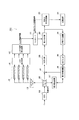
図1は、本発明の第1の実施形態におけるディジタルビデオカメラ(画像符号化装置)100の概略構成を示す図である。本実施形態におけるディジタルビデオカメラ100は、符号化処理においてマクロブロック単位で量子化を行い、その量子化スケールコードの決定にDCTブロックのエッジ情報を利用する点に特徴がある。
FIG. 1 is a diagram showing a schematic configuration of a digital video camera (image encoding apparatus) 100 according to the first embodiment of the present invention. The
図1において、101は、例えばCCD(電荷結合素子)などの撮像素子及びA/D変換器等を含む撮像部であり、映像信号(動画像データ)を出力する。102は、フレームバッファであり、入力された映像信号を一時的に格納する。103はDCT回路であり、104は量子化回路であり、105は逆量子化回路であり、106はIDCT(逆DCT)回路であり、107は動き推定回路であり、108は動き補償回路である。また、109は可変長符号化回路である。110は記録媒体であり、可変長符号化回路109で符号化された後の映像データを記録する。記録媒体110は、例えば着脱式のDVD等の光ディスク、半導体メモリカード、或いは磁気テープである。内蔵式のハードディスク等であっても良い。116は、減算回路である。尚、図1に示した符号102〜110は、図4に示した符号402〜410と、図1に示した符号116は、図4に示した符号413と、それぞれ同様の機能を有する。
In FIG. 1,
また、111はコントローラであり、量子化回路104における量子化スケールコードの制御を行うほかにシステム全体の制御も行う。112はマクロブロックバッファであり、フレームバッファ102に保存されている動画像データに対して、これから符号化を行うマクロブロックデータと同じデータを保持するメモリである。113はDCTブロックバッファであり、マクロブロックバッファ112に保持されているマクロブロックデータをDCTブロックに分割したデータを格納する。尚、図1に示すようにDCTブロックバッファ113は、4つある。これはMPEG2の場合、マクロブロック内に4つのDCTブロックが含まれることに対応している。114はエッジ検出回路であり、各DCTブロックバッファ113に保持されたデータに対してエッジ検出を行い、エッジ強度を求める。115はエッジ強度算出回路であり、エッジ検出回路114が求めたDCTブロック別のエッジ強度を用いてマクロブロックのエッジ強度を決定する。
次に、ディジタルビデオカメラ100の符号化動作について説明する。CCD101における撮像動作によって得られた映像信号は、フレームバッファ102に一旦保持され、符号化ピクチャが画面内符号化(イントラ符号化)方式の時は、映像信号をマクロブロックに分割し、DCT回路103においてマクロブロック内の信号に対してDCT処理を行い、コントローラ111で決定した量子化スケールコードを用いて量子化回路104でDCT係数を量子化した後、可変長符号化回路109で可変長符号化する。
Next, the encoding operation of the
また、符号化ピクチャが画面間符号化ピクチャ(インター符号化)方式の時は、まず、すでに符号化されたピクチャに対して逆量子化回路105で逆量子化を行い、IDCT回路106で逆DCT処理を行ったローカルデコード画像を作成する。次に、フレームバッファ102に保持されている映像信号である符号化対象のピクチャを用いて動き推定及び動き補償を行い、動き補償が行われたローカルデコード画像を生成する。さらに減算回路116によって、フレームバッファ102に保持されている映像信号と動き補償が行われたローカルデコード画像の信号との差分値を算出する。算出された差分値を用いて、DCT回路103においてマクロブロック内の信号に対してDCT処理を行い、コントローラ111で決定した量子化スケールコードを用いて量子化回路104でDCT係数を量子化した後、可変長符号化回路109で可変長符号化する。
When the encoded picture is an inter-picture encoded picture (inter-encoded) system, first, an
以上がディジタルビデオカメラ100の符号化動作の概要であるが、ここで、量子化回路104で使用する量子化スケールコードの決定に関するコントローラ部111の動作の詳細について説明する。
The above is the outline of the encoding operation of the
コントローラ111は、GOP内の各ピクチャに対する割り当てビット量を、割り当て対象ピクチャを含めGOP内でまだ符号化されていないピクチャに対して割り当てられるビット量を基にして配分する。この配分をGOP内の符号化ピクチャ順に繰り返し、ピクチャごとにピクチャ目標ビット量を設定する。次に、コントローラ111は、各ピクチャに対する割り当てビット量と実際の発生ビット量とを一致させるため、可変長符号化回路109から得られる仮想バッファの容量(VBVバッファ容量)の情報を基に、量子化スケールの基準値をマクロブロック単位のフィードバック制御で求める。以上の動作は先述したステップ1、ステップ2と同様である。
The
さらに、フレームバッファ102に保持された映像信号のうち、今から符号化するマクロブロックと同じデータを画像マクロブロックバッファ112に保持する。なお、このマクロブロックバッファ112は動き補償回路108で使用するマクロブロックバッファと共通化しても良い。マクロブロックバッファ112に保持された画像データは、マクロブロックよりもサイズが小さいDCTブロックに分割されて、各DCTブロックバッファ113に保持される。そして、各DCTブロックバッファ113に保持された画像データ(DCTブロックデータ)を用いて、エッジ検出回路114は各DCTブロックにおけるエッジ強度を検出する。さらにエッジ強度算出回路115は、各DCTブロックの画像データに対して検出されたエッジ強度のうち、最高のエッジ強度を算出し、算出されたエッジ強度に関する情報(エッジ強度情報)をコントローラ111へ出力する。このエッジ強度情報は、マクロブロックのエッジの強度を決定することに用いられる。
Further, among the video signals held in the
なお、エッジ検出及び強度の算出手段に関しては、従来から様々な手法が提案されており、任意の方法を用いてもよい。ここでは、いくつかのエッジ検出回路とそのエッジ強度算出回路の一例を挙げる。例えば、空間領域を利用するものであれば、キャニーエッジ検出器やゾーベルエッジ検出器などのエッジ検出回路によるエッジ検出処理をDCTブロック内の各画素に対して行い、所定の閾値を超える画素数とDCTブロックの画素数の割合をエッジ強度として算出する。周波数領域を利用するものであれば、DCT変換やアダマール変換などの直交変換をDCTブロックに対して行い、垂直エッジ成分、水平エッジ成分、対角エッジ成分に対応する直交変換係数の絶対値和または二乗和を算出して、これらの情報を用いてエッジ強度を算出することも可能である。 Various methods have been proposed for edge detection and intensity calculation means, and any method may be used. Here, examples of some edge detection circuits and their edge strength calculation circuits are given. For example, if a spatial region is used, edge detection processing by an edge detection circuit such as a canny edge detector or a Sobel edge detector is performed on each pixel in the DCT block, and the number of pixels exceeding a predetermined threshold and the DCT The ratio of the number of pixels in the block is calculated as the edge strength. If the frequency domain is used, orthogonal transformation such as DCT transformation and Hadamard transformation is performed on the DCT block, and the sum of absolute values of orthogonal transformation coefficients corresponding to vertical edge component, horizontal edge component, diagonal edge component or It is also possible to calculate the sum of squares and use this information to calculate the edge strength.
コントローラ111は、前述の計算により算出した量子化スケールコードの基準値を、エッジ強度算出回路115で算出されたエッジ強度情報に応じて調節することで、実際に量子化するための量子化スケールコードを算出する。またエッジ強度情報がゼロ、つまりマクロブロック内にエッジが存在しない場合ことを示す場合には、量子化スケールコードの基準値を実際に量子化するための量子化スケールコードとして利用する。
The
以下、図面を用いてマクロブロック毎の状況に応じたエッジ強度の算出方法の一例を示す。図2(A)、(B)、(C)は、マクロブロック毎の状況に応じたエッジ強度の算出方法例を示す図である。図2(A)では、マクロブロック内における各DCTブロックに対してエッジ検出回路114においてエッジ検出を行った結果、1つのDCTブロック201だけにエッジが存在していると判定された場合を示している。この場合には、エッジ強度算出回路115は、マクロブロックにエッジが存在すると判断し、エッジを含むDCTブロック201のエッジ強度をマクロブロックのエッジ強度として出力する。これにより、コントローラ111は、エッジ強度算出回路115が出力したエッジ強度に応じて量子化スケールコードの基準値を下げて実際量子化するための量子化スケールコードを算出する。
Hereinafter, an example of an edge strength calculation method corresponding to the situation of each macroblock will be described using the drawings. 2A, 2 </ b> B, and 2 </ b> C are diagrams illustrating examples of edge strength calculation methods according to the situation of each macroblock. FIG. 2A shows a case where it is determined that an edge exists in only one DCT block 201 as a result of performing edge detection in the
また、図2(B)では、マクロブロック内における各DCTブロックに対してエッジ検出を行った結果、DCTブロック202とDCTブロック203にエッジが存在していると判定された場合を示している。この場合には、エッジ強度算出回路115は、マクロブロックにエッジが存在すると判断し、DCTブロック202のエッジ強度とDCTブロック203のエッジ強度を比較して大きい方をマクロブロックのエッジ強度として出力する。すなわち、マクロブロック内で最大となるDCTブロックのエッジ強度を採用する。これにより、コントローラ111は、エッジ強度算出回路115が出力したエッジ強度に応じて量子化スケールコードの基準値を下げて実際量子化するための量子化スケールコードを算出する。
FIG. 2B shows a case where it is determined that edges exist in the DCT block 202 and the DCT block 203 as a result of performing edge detection on each DCT block in the macroblock. In this case, the edge
また、図2(C)では、マクロブロック内における各DCTブロックに対してエッジ検出を行った結果、どのDCTブロックにもエッジが存在しないと判定された場合を示している。この場合には、エッジ強度算出回路115は、マクロブロックにエッジが存在しないと判断し、エッジ強度を出力しない(又は、エッジ強度=0を出力してもよい)。これにより、コントローラ111は、量子化スケールコードの基準値をそのまま実際量子化するための量子化スケールコードとして利用する。
FIG. 2C illustrates a case where it is determined that no edge exists in any DCT block as a result of performing edge detection on each DCT block in the macroblock. In this case, the edge
コントローラ111において算出された量子化スケールコードは、量子化回路104の量子化スケールコードとして設定され、当該マクロブロック内に含まれるDCTブロックの量子化に使用される。
The quantization scale code calculated by the
以上に説明したように、本実施形態の画像符号化装置においては、動画像の符号化処理において、マクロブロックよりも小さいブロックであるDCTブロックにおけるエッジ情報をマクロブロックのエッジ情報として利用して、当該マクロブロックの量子化スケールコードの決定処理を行うので、部分的にエッジを含むマクロブロックの画質劣化を防ぐことが可能となる。また、マクロブロックに含まれる複数のDCTブロックからエッジが検出された場合には、図2Bに示すように、最大のエッジ強度をマクロブロックのエッジ強度としている。これにより、例えば複数のDCTブロックから検出されたエッジの一つがノイズ成分を誤検出したものであった場合でも、通常、ノイズ成分はエッジ強度が弱いので、この誤検出によるエッジ強度が弱いという誤った情報が、量子化スケールコードの決定に影響することを防ぐことができる。 As described above, in the image coding apparatus of the present embodiment, in the moving image coding processing, edge information in a DCT block that is a block smaller than a macroblock is used as edge information of a macroblock, Since the determination process of the quantization scale code of the macroblock is performed, it is possible to prevent the image quality deterioration of the macroblock partially including the edge. When an edge is detected from a plurality of DCT blocks included in the macroblock, the maximum edge strength is set as the macroblock edge strength as shown in FIG. 2B. As a result, for example, even when one of the edges detected from a plurality of DCT blocks is an erroneous detection of a noise component, the noise component usually has a weak edge strength. It is possible to prevent the received information from affecting the determination of the quantization scale code.
(第2の実施形態)
次に、第2の実施形態として、DCTブロックのエッジ強度とエッジの方向を考慮して量子化スケールコードを決定する画像符号化装置について説明する。具体的には、当該マクロブロックに含まれる各DCTブロックのエッジ強度とエッジ方向の情報から、マクロブロックにおいてエッジが視覚的に目立つか否かを判断し、その判断に応じた係数をエッジ強度に乗算する処理を行う。尚、第2の実施形態における画像符号化装置の構成は、図1に示した第1の実施形態における符号化装置の構成と同様であり、説明を省略する。
(Second Embodiment)
Next, as a second embodiment, an image encoding apparatus that determines a quantization scale code in consideration of the edge strength and edge direction of a DCT block will be described. Specifically, it is determined from the edge strength and edge direction information of each DCT block included in the macroblock whether or not the edge is visually noticeable in the macroblock, and the coefficient corresponding to the determination is used as the edge strength. Performs multiplication. The configuration of the image encoding device in the second embodiment is the same as the configuration of the encoding device in the first embodiment shown in FIG.
コントローラ111は、第1の実施形態と同様に量子化スケールの基準値をマクロブロック単位の符号量制御で求める。さらに、フレームバッファ102に保持された映像信号のうち、これから符号化するマクロブロックと同じ画像データをマクロブロックバッファ112に保持する。マクロブロックバッファ112に保持された画像データは、マクロブロックよりもサイズが小さいDCTブロックに分割されて、各DCTブロックバッファ113に保持される。そして、各DCTブロックバッファ113に保持された画像データ(DCTブロックデータ)を用いて、エッジ検出回路114は各DCTブロックにおけるエッジ強度と方向を検出する。
The
各DCTブロックのエッジ強度は、上述した実施形態1と同様の手法で検出することが可能である。エッジ方向は、空間領域ならびに周波数領域などを用いた様々な手法が提案されており、任意の手法を用いて検出できる。例えば、空間領域を利用するものであれば、垂直エッジ方向、水平エッジ方向、対角エッジ方向それぞれの方向を検出するエッジ検出器をDCTブロック内の各画素に対して行い、最も多い方向を当該DCTブロックのエッジ方向とする。また、周波数領域を利用するものであれば、直交変換後の垂直エッジ成分、水平エッジ成分、対角エッジ成分に対応する直交変換係数の絶対値和ならびに二乗和を比較して、最も高い値をもつ方向を当該DCTブロックのエッジ方向とする。 The edge strength of each DCT block can be detected by the same method as in the first embodiment. Various methods using the spatial domain and the frequency domain have been proposed for the edge direction, and can be detected using an arbitrary method. For example, if a spatial region is used, an edge detector that detects each of the vertical edge direction, the horizontal edge direction, and the diagonal edge direction is applied to each pixel in the DCT block, and the most common direction is The edge direction of the DCT block is assumed. If the frequency domain is used, the absolute value sum and the square sum of the orthogonal transformation coefficients corresponding to the vertical edge component, horizontal edge component, and diagonal edge component after orthogonal transformation are compared, and the highest value is obtained. This direction is the edge direction of the DCT block.
エッジ検出回路114は、上記に例示した手法等により、マクロブロック内における各DCTブロックのエッジ強度ならびにエッジ方向を検出して、その検出結果をエッジ強度算出回路115に出力する。さらにエッジ強度算出回路115は、各DCTブロックの画像データに対して検出されたエッジ強度及び方向に関する情報をマクロブロック単位にまとめて、エッジが視覚的に目立つか否かを判断し、その判断結果に応じたエッジ強度情報をコントローラ111へ出力する。このエッジ強度情報は、マクロブロックのエッジの強度を決定することに用いられる。コントローラ111は、前述の計算により算出した量子化スケールコードの基準値を、エッジ強度算出回路115で算出されたエッジ強度情報に応じて調節することで、実際に量子化するための量子化スケールコードを算出する。
The
以下、第2の実施形態におけるエッジ強度及びエッジ方向に関する情報の処理例について図を用いて説明する。図3(A)、(B)、(C)、(D)は、第2の実施形態におけるエッジ強度及びエッジ方向に関する情報の処理例を示す図である。尚、図3(A)〜(D)の例においては輝度成分のみを示しており、各マクロブロックは4つの輝度成分のDCTブロックから構成されていることを示している。また、図3(A)及び(B)は、エッジ方向の配置から視覚的にエッジが目立つと判断される場合を示し、図3(C)及び(D)は、エッジ方向の配置から視覚的にエッジが目立たないと判断される場合を示している。 Hereinafter, a processing example of information on edge strength and edge direction in the second embodiment will be described with reference to the drawings. FIGS. 3A, 3 </ b> B, 3 </ b> C, and 3 </ b> D are diagrams illustrating an example of information processing related to edge strength and edge direction according to the second embodiment. In the examples of FIGS. 3A to 3D, only the luminance component is shown, and each macroblock is composed of DCT blocks having four luminance components. FIGS. 3A and 3B show a case where it is determined that the edge is visually conspicuous from the arrangement in the edge direction. FIGS. 3C and 3D show the case where the edge is visually noticeable from the arrangement in the edge direction. The case where it is determined that the edge is not conspicuous is shown.
例えば、図3(A)のマクロブロックに示すように、水平方向に隣接したDCTブロックがともに水平エッジであると検出されている場合、又は、図3(B)に示すように垂直方向に隣接したDCTブロックがともに垂直エッジであると検出されている場合には、エッジ強度算出回路115は、視覚的に目立つエッジが存在すると判断し、実施の形態1と同様の方法で算出したエッジ強度に所定の重み係数を乗算した値をエッジ強度情報として出力する。コントローラ111は、エッジ強度算出回路115が出力するエッジ強度情報に応じて量子化スケールコードの基準値を下げて実際量子化するための量子化スケールコードを算出する。
For example, as shown in the macroblock in FIG. 3A, when both DCT blocks adjacent in the horizontal direction are detected as horizontal edges, or in the vertical direction as shown in FIG. When both of the DCT blocks detected as vertical edges are detected, the edge
また、図3(C)や図3(D)のマクロブロックに示すように、全てのDCTブロックからエッジが検出されたが、各DCTブロックのエッジ方向がバラバラであることが検出されると、エッジ強度算出回路115は、マクロブロック内にエッジは存在するが視覚的に目立たないエッジであると判断し、マクロブロックにエッジが存在しない場合と同様の処理(図2(C)と同様の処理)を行う。これにより、コントローラ111は、量子化スケールコードの基準値をそのまま実際量子化するための量子化スケールコードとして利用する。
Further, as shown in the macroblocks of FIG. 3C and FIG. 3D, edges are detected from all the DCT blocks, but when the edge directions of each DCT block are detected to be different, The edge
また、エッジ検出回路114において検出されたエッジ強度が小さいあるいはエッジがないことが検出された場合は、マクロブロックが平坦部または高周波成分を多く含んだテクスチャ部(以下、単にテクスチャ部とする)の可能性が高い。人間の視覚特性として一般的に平坦部はノイズが目立ちやすく、テクスチャ部はノイズが目立ちにくいと言われている。そのため、エッジ強度が小さいあるいはエッジがないと算出されたエッジ強度情報を受信した場合、コントローラ111は、エッジ検出以外の情報を利用して平坦部かテクスチャ部かの判断及び分離処理を行う。平坦部とテクスチャ部の判断及び分離処理には、空間領域であれば分散値、周波数領域であれば直交変換のAC成分の絶対値和ならびに二乗和で判断し分離する方法などが好適である。
When the
コントローラ111は、平坦なマクロブロックに対しては量子化スケールコードの基準値を下げて実際量子化するための量子化スケールコードを算出し、テクスチャ部に対しては量子化スケールコードの基準値を上げて実際量子化するための量子化スケールコードを算出する。コントローラ111は、算出した量子化スケールコードを、量子化回路104の量子化スケールコードとして設定する。これにより、この量子化スケールコードが、当該マクロブロック内に含まれるDCTブロックの量子化に使用される。
The
以上に説明したように、本実施形態の画像符号化装置においては、動画像の符号化処理において、マクロブロックよりも小さいブロックであるDCTブロックにおけるエッジ情報をマクロブロックのエッジ情報として利用して、当該マクロブロックの量子化スケールコードの決定処理を行うので、部分的にエッジを含むマクロブロックの画質劣化を防ぐことが可能となる。更に、エッジ情報として各DCTブロックのエッジ方向を考慮して視覚的に目立つエッジであるか否かを判断し、目立つエッジであると判断した場合には、エッジ強度に対して所定の重み係数を乗算することで、同じエッジ強度であっても視覚的に目立つエッジ程、更に大きな値のエッジ強度として出力するので、視覚的に目立つエッジに対して適切な量子化を行う量子化スケールコードを決定することができる。 As described above, in the image coding apparatus of the present embodiment, in the moving image coding processing, edge information in a DCT block that is a block smaller than a macroblock is used as edge information of a macroblock, Since the determination process of the quantization scale code of the macroblock is performed, it is possible to prevent the image quality deterioration of the macroblock partially including the edge. Further, the edge direction of each DCT block is considered as edge information to determine whether the edge is visually conspicuous. When it is determined that the edge is conspicuous, a predetermined weight coefficient is set for the edge strength. By multiplying, even if the edge strength is the same, the more visually noticeable edge is output as a larger edge strength, so the quantization scale code that performs appropriate quantization on the visually noticeable edge is determined. can do.
(第3の実施形態)
次に、第3の実施形態として、DCTブロックのエッジ強度とエッジ方向を考慮して量子化スケールコードを決定する画像符号化装置について説明する。具体的には、当該マクロブロックに含まれる各DCTブロックと、当該マクロブロックに隣接するマクロブロックに含まれるDCTブロックのエッジ強度とエッジ方向の情報から、当該マクロブロックにおいてエッジが視覚的に目立つか否かを判断し、その判断に応じた係数をエッジ強度に乗算する処理を行う。尚、第3の実施形態における画像符号化装置の構成は、図1に示した第1の実施形態における符号化装置の構成と同様であり、説明を省略する。
(Third embodiment)
Next, as a third embodiment, an image coding apparatus that determines a quantization scale code in consideration of the edge strength and edge direction of a DCT block will be described. Specifically, from the information on the edge strength and edge direction of each DCT block included in the macroblock and the DCT block included in the macroblock adjacent to the macroblock, whether the edge is visually noticeable in the macroblock. It is determined whether or not, and the edge strength is multiplied by a coefficient corresponding to the determination. Note that the configuration of the image encoding device according to the third embodiment is the same as the configuration of the encoding device according to the first embodiment shown in FIG.
コントローラ111は、第1の実施形態のときと同様に量子化スケールの基準値をマクロブロック単位の符号量制御で求める。さらに、フレームバッファ102に保持された映像信号のうち、これから符号化するマクロブロックと同じ画像データをマクロブロックバッファ112に保持する。マクロブロックバッファ112に保持された画像データは、マクロブロックよりもサイズが小さいDCTブロックに分割されて、各DCTブロックバッファ113に保持される。そして、各DCTブロックバッファ113に保持された画像データ(DCTブロックデータ)を用いて、エッジ検出回路114は各DCTブロックにおけるエッジ強度とエッジ方向を検出する。
The
各DCTブロックのエッジ強度は、上述した実施形態1と同様の手法で検出することが可能である。さらにエッジ方向は、上述した実施形態2と同様の手法で検出することが可能である。 The edge strength of each DCT block can be detected by the same method as in the first embodiment. Furthermore, the edge direction can be detected by the same method as in the second embodiment described above.
エッジ検出回路114は、上記に例示した手法等により、1つのマクロブロック内における各DCTブロックのエッジ強度ならびにエッジ方向を検出して、その検出結果をエッジ強度算出回路115に出力する。そしてエッジ強度算出回路115は、各DCTブロックに対して検出されたエッジ強度及び方向に関する情報をマクロブロック単位にまとめて、エッジが視覚的に目立つか否かを判断する。さらに、符号化対象のマクロブロックに隣接する、既に符号化済のマクロブロックにおける各DCTブロックに対して検出されたエッジ強度及び方向に関する情報を参照して、マクロブロックを跨いでエッジが視覚的に目立つか否かを判断する。それらの判断結果に応じたエッジ強度情報をコントローラ111へ出力する。このエッジ強度情報は、マクロブロックのエッジの強度を決定することに用いられる。コントローラ111は、前述の計算により算出した量子化スケールコードの基準値を、エッジ強度算出回路115で算出されたエッジ強度情報に応じて調節することで、実際に量子化するための量子化スケールコードを算出する。
The
以下、第3の実施形態におけるエッジ強度及びエッジ方向に関する情報の処理例について図を用いて説明する。図5(A)、(B)、(C)は、第3の実施形態におけるエッジ強度及びエッジ方向に関する情報の処理例を示す図である。尚、図5(A)〜(C)の例においては輝度成分のみを示している。また、図5(A)、(B)、(C)の符号500は符号化対象のマクロブロックを示し、マクロブロック500が符号501〜504で表わされる4つの輝度成分のDCTブロックから構成されていることを示している。またマクロブロック500には同じサイズのマクロブロックが隣接していることを示しており、各マクロブロックも4つの輝度成分のDCTブロックから構成されている。またDCTブロック501は符号502〜509で表わされる各DCTブロックが隣接していることを示している。
Hereinafter, a processing example of information regarding edge strength and edge direction in the third embodiment will be described with reference to the drawings. FIGS. 5A, 5 </ b> B, and 5 </ b> C are diagrams illustrating an example of information processing related to edge strength and edge direction according to the third embodiment. In the examples of FIGS. 5A to 5C, only the luminance component is shown. Also,
このような構成において、例えば図5(B)のように、DCTブロック501及び502が水平エッジと検出され、さらに、DCTブロック501に水平に隣接するDCTブロック508も水平エッジであると検出されている場合は、エッジ強度算出回路115は、DCTブロック501、502には水平エッジがあり、さらにそのエッジはマクロブロック500だけでなく複数マクロブロックに渡って継続した視覚的に目立つエッジであると判断する。そこで、実施の形態1と同様の方法で算出したエッジ強度に所定の重み係数を乗算した値をマクロブロック500のエッジ強度情報として出力する。コントローラ111は、エッジ強度算出回路115が出力するエッジ強度情報に応じて量子化スケールコードの基準値を下げて、マクロブロック500を実際に量子化するための量子化スケールコードを算出する。
In such a configuration, for example, as shown in FIG. 5B, the DCT blocks 501 and 502 are detected as horizontal edges, and the DCT block 508 horizontally adjacent to the
また、図5(C)のように、DCTブロック501が水平エッジと検出され、DCTブロック501に水平に隣接するDCTブロック502はエッジが存在せず、さらに、DCTブロック501に水平に隣接するDCTブロック508が水平エッジであると検出されている場合は、エッジ強度算出回路115は、水平エッジがマクロブロック500だけでなく複数マクロブロックに渡って継続してかつ、マクロブロック500がエッジの終点となる視覚的に目立つエッジであると判断する。そこで、実施の形態1と同様の方法で算出したエッジ強度に所定の重み係数を乗算した値をマクロブロック500のエッジ強度情報として出力する。コントローラ111は、エッジ強度算出回路115が出力するエッジ強度情報に応じて量子化スケールコードの基準値を下げて、マクロブロック500を実際に量子化するための量子化スケールコードを算出する。
Further, as shown in FIG. 5C, the
なお、図5(B)及び図5(C)は水平方向に対する説明を行ったが、垂直方向並びに対角方向に関しても同様の処理を行うことが可能である。 Although FIG. 5B and FIG. 5C have been described with respect to the horizontal direction, the same processing can be performed in the vertical direction and the diagonal direction.
以上説明したように、本実施形態の画像符号化装置においては、動画像の符号化処理において、マクロブロックよりも小さいブロックであるDCTブロックにおけるエッジ情報をマクロブロックのエッジ情報として利用して、さらに隣接するマクロブロック内のDCTブロックにおけるエッジ情報も参照して、符号化対象のマクロブロックの量子化スケールコードの決定処理を行うので、部分的にエッジを含むマクロブロックの画質劣化を防ぐことが可能となる。更に、複数マクロブロックに渡って継続するようなエッジであると判断した場合には、エッジ強度に対して所定の重み係数を乗算することで、同じエッジ強度であっても視覚的に目立つエッジ程、更に大きな値のエッジ強度として出力するので、視覚的に目立つエッジに対して適切な量子化を行う量子化スケールコードを決定することができる。 As described above, in the image coding apparatus according to the present embodiment, in the moving image coding processing, edge information in a DCT block that is a block smaller than a macroblock is used as edge information of a macroblock. Since the quantization scale code of the macroblock to be encoded is determined by referring to the edge information in the DCT block in the adjacent macroblock as well, it is possible to prevent deterioration of the image quality of the macroblock partially including the edge. It becomes. Furthermore, when it is determined that the edge continues over a plurality of macroblocks, the edge strength is multiplied by a predetermined weighting factor, so that the edge that is visually conspicuous is obtained even at the same edge strength. Since the edge strength is output as a larger value, the quantization scale code for performing appropriate quantization on the visually conspicuous edge can be determined.
(その他の実施形態)
次に、その他の実施形態を紹介する。上記した第1〜第3の実施形態はMPEG符号化方式における量子化スケールコードの制御について説明したが、同様の考えをMPEG4−AVC/H.264符号化方式に適用する例を説明する。尚、MPEG4−AVC/H.264符号化方式のブロック図は図1で代用的に説明できるので省略する。
(Other embodiments)
Next, other embodiments will be introduced. In the first to third embodiments described above, the control of the quantization scale code in the MPEG encoding system has been described. However, the same idea is applied to the MPEG4-AVC / H. An example applied to the H.264 encoding method will be described. Note that MPEG4-AVC / H. Since the block diagram of the H.264 encoding method can be described as a substitute in FIG.
図6はMPEG4−AVC/H.264形式におけるマクロブロックと、マクロブロックに含まれる整数変換ブロックである。MPEG4−AVC/H.264形式ではMPEGでのDCTに相当する整数変換の単位はプロファイルによって異なっている。メインプロファイルであれば、整数変換の単位は水平方向4画素、垂直方向4画素であり、マクロブロック内に16個の輝度成分の整数変換ブロックが存在する。またハイプロファイルであれば整数変換の単位は水平方向8画素、垂直方向8画素であり、マクロブロック内に4個の輝度成分の整数変換ブロックが存在する。 FIG. 6 shows MPEG4-AVC / H. A macro block in the H.264 format and an integer conversion block included in the macro block. MPEG4-AVC / H. In the H.264 format, the unit of integer conversion corresponding to DCT in MPEG differs depending on the profile. In the main profile, the unit of integer conversion is 4 pixels in the horizontal direction and 4 pixels in the vertical direction, and there are 16 luminance component integer conversion blocks in the macroblock. In the case of a high profile, the unit of integer conversion is 8 pixels in the horizontal direction and 8 pixels in the vertical direction, and there are four integer conversion blocks of luminance components in the macroblock.
図6(A)は、MPEG4−AVC/H.264符号化方式のメインプロファイルで符号化を行う際のマクロブロックと整数変換の関係を示した図であり、マクロブロックに含まれる601〜616は整数変換ブロックである。図6(B)〜(D)はエッジ強度、エッジ方向に関する情報の処理例を示す図である。 FIG. 6A shows MPEG4-AVC / H. It is the figure which showed the relationship between the macroblock at the time of encoding by the main profile of a H.264 encoding system, and integer conversion, and 601-616 contained in a macroblock are integer conversion blocks. FIGS. 6B to 6D are diagrams illustrating processing examples of information regarding edge strength and edge direction.
図6(B)では、マクロブロック内における各整数変換ブロックに対してエッジ検出を行った結果、1つの整数変換ブロック617だけにエッジが存在していると判定された場合を示している。この場合には、エッジ強度算出回路115は、マクロブロックにエッジが存在すると判断し、その整数変換ブロック617のエッジ強度をマクロブロックのエッジ強度として出力する(第1の実施形態で説明した図2(A)と同様の処理)。
FIG. 6B shows a case where it is determined that an edge exists only in one integer transform block 617 as a result of performing edge detection for each integer transform block in the macroblock. In this case, the edge
また、図6(C)では、マクロブロック内における各整数変換ブロックに対してエッジ検出を行った結果、整数変換ブロック618と整数変換ブロック619にエッジが存在していると判定された場合を示している。この場合には、エッジ強度算出回路115は、マクロブロックにエッジが存在すると判断し、整数変換ブロック618のエッジ強度と整数変換ブロック619のエッジ強度を比較して大きい方をマクロブロックのエッジ強度として出力する(第1の実施形態で説明した図2(B)と同様の処理)。
FIG. 6C shows a case where it is determined that edges exist in the
尚、マクロブロック内における各整数変換ブロックに対してエッジ検出を行った結果、どの整数変換ブロックにもエッジが存在しないと判定された場合には、エッジ強度算出回路115は、マクロブロックにエッジが存在しないと判断しエッジ強度を出力しない。(第1の実施形態で説明した図2(C)と同様の処理)。
As a result of performing edge detection for each integer transform block in the macro block, if it is determined that no edge exists in any integer transform block, the edge
また、図6(D)のマクロブロックに示すように、水平方向に隣接した整数変換ブロック620〜623がともに水平エッジであると判定されている場合、又は、図示していないが、垂直方向に隣接した整数変換ブロックが垂直エッジであると判定されている場合には、エッジ強度算出回路115は、マクロブロックには、視覚的に目立つエッジが存在すると判断し、エッジ強度に所定の重み係数を乗算した値をマクロブロックのエッジ強度として出力する(第2の実施形態で説明した図3(A)、(B)と同様の処理)。
Further, as shown in the macroblock of FIG. 6D, when it is determined that the integer conversion blocks 620 to 623 adjacent in the horizontal direction are both horizontal edges, or although not shown, in the vertical direction When it is determined that the adjacent integer transform block is a vertical edge, the edge
尚、マクロブロック内における各整数変換ブロックに対してエッジ検出を行った結果、全ての整数変換ブロックからエッジが検出されたが、各整数変換ブロックのエッジ方向がバラバラであると判定されると、エッジ強度算出回路115は、マクロブロック内にエッジは存在するが視覚的に目立たないエッジであると判断し、マクロブロックにエッジが存在しない場合と同様の処理を行うことも可能である(第2の実施形態で説明した図3(C)、(D)と同様の処理)。
As a result of performing edge detection for each integer transform block in the macro block, edges are detected from all integer transform blocks, but when it is determined that the edge directions of each integer transform block are disjoint, The edge
更に、第3の実施形態と同様に、符号化対象のマクロブロックに隣接するマクロブロックに含まれる整数変換ブロックのエッジ強度とエッジ方向の情報から、符号化対象のマクロブロックにおいてエッジが視覚的に目立つか否かを判断し、その判断に応じた係数をエッジ強度に乗算する処理を行うことも可能である。 Further, as in the third embodiment, the edge is visually determined in the encoding target macroblock from the edge strength and edge direction information of the integer transform block included in the macroblock adjacent to the encoding target macroblock. It is also possible to determine whether or not the image is conspicuous and to multiply the edge strength by a coefficient corresponding to the determination.
尚、上述した実施形態において図1に示したエッジ検出回路114及びエッジ強度算出回路115における各処理は、各処理の機能を実現する為のプログラムをメモリから読み出してCPU(中央演算装置)が実行することによりその機能を実現させるものであってもよい。
In the above-described embodiment, each processing in the
また、図1に示したエッジ検出回路114及びエッジ強度算出回路115における各処理の一部の機能を専用のハードウェアにより実現してもよい。また、CPUがアクセスする上記メモリとしては、HDD、光ディスク、フラッシュメモリ等の不揮発性のメモリや、CD−ROM等の読み出しのみが可能な記録媒体、RAM以外の揮発性のメモリ、あるいはこれらの組合せによるコンピュータ読み取り、書き込み可能な記録媒体より構成されてもよい。
In addition, some functions of each process in the
また、図1に示したエッジ検出回路114及びエッジ強度算出回路115における各処理の機能を実現する為のプログラムをコンピュータ読み取り可能な記録媒体に記録して、この記録媒体に記録されたプログラムをコンピュータシステムに読み込ませ、実行することにより各処理を行っても良い。なお、ここでいう「コンピュータシステム」とは、OSや周辺機器等のハードウェアを含むものとする。具体的には、記憶媒体から読み出されたプログラムが、コンピュータに挿入された機能拡張ボードやコンピュータに接続された機能拡張ユニットに備わるメモリに書きこまれた後、そのプログラムの指示に基づき、その機能拡張ボードや機能拡張ユニットに備わるCPUなどが実際の処理の一部または全部を行い、その処理によって前述した実施形態の機能が実現される場合も含む。
Further, a program for realizing the functions of the respective processes in the
また、「コンピュータ読み取り可能な記録媒体」とは、フレキシブルディスク、光磁気ディスク、ROM、CD−ROM等の可搬媒体、コンピュータシステムに内蔵されるハードディスク等の記憶装置のことをいう。さらに「コンピュータ読み取り可能な記録媒体」とは、インターネット等のネットワークや電話回線等の通信回線を介してプログラムが送信された場合のサーバやクライアントとなるコンピュータシステム内部の揮発メモリ(RAM)のように、一定時間プログラムを保持しているものも含むものとする。 The “computer-readable recording medium” refers to a storage device such as a flexible medium, a magneto-optical disk, a portable medium such as a ROM and a CD-ROM, and a hard disk incorporated in a computer system. Further, the “computer-readable recording medium” refers to a volatile memory (RAM) in a computer system that becomes a server or a client when a program is transmitted via a network such as the Internet or a communication line such as a telephone line. In addition, those holding a program for a certain period of time are also included.
また、上記プログラムは、このプログラムを記憶装置等に格納したコンピュータシステムから、伝送媒体を介して、あるいは、伝送媒体中の伝送波により他のコンピュータシステムに伝送されてもよい。ここで、プログラムを伝送する「伝送媒体」は、インターネット等のネットワーク(通信網)や電話回線等の通信回線(通信線)のように情報を伝送する機能を有する媒体のことをいう。 The program may be transmitted from a computer system storing the program in a storage device or the like to another computer system via a transmission medium or by a transmission wave in the transmission medium. Here, the “transmission medium” for transmitting the program refers to a medium having a function of transmitting information, such as a network (communication network) such as the Internet or a communication line (communication line) such as a telephone line.
また、上記プログラムは、前述した機能の一部を実現する為のものであっても良い。さらに、前述した機能をコンピュータシステムに既に記録されているプログラムとの組合せで実現できるもの、いわゆる差分ファイル(差分プログラム)であっても良い。 The program may be for realizing a part of the functions described above. Furthermore, what can implement | achieve the function mentioned above in combination with the program already recorded on the computer system, and what is called a difference file (difference program) may be sufficient.
また、上記のプログラムを記録したコンピュータ読み取り可能な記録媒体等のプログラムプロダクトも本発明の実施形態として適用することができる。上記のプログラム、記録媒体、伝送媒体およびプログラムプロダクトは、本発明の範疇に含まれる。 A program product such as a computer-readable recording medium in which the above program is recorded can also be applied as an embodiment of the present invention. The above program, recording medium, transmission medium, and program product are included in the scope of the present invention.
以上、この発明の実施形態について図面を参照して詳述してきたが、具体的な構成はこの実施形態に限られるものではなく、この発明の要旨を逸脱しない範囲の設計等も含まれる。 The embodiment of the present invention has been described in detail with reference to the drawings. However, the specific configuration is not limited to this embodiment, and includes designs and the like that do not depart from the gist of the present invention.
Claims (8)
符号化対象の第1のブロックを更に複数に分割して得られる第2のブロックに含まれるエッジを検出するエッジ検出手段と、
前記エッジ検出手段により前記第2のブロックにエッジが検出された場合に、検出されたエッジについてエッジ強度を算出し、前記符号化対象の第1のブロック内の複数の前記第2のブロックの中で算出されたエッジ強度が最大となるものを決定する算出手段と、
前記算出手段により決定された最大のエッジ強度に基づいて、前記符号化手段に対して前記符号化対象の第1のブロックの量子化スケールを設定するための制御情報を出力する符号化制御手段とを備え、
前記算出手段は、前記検出されたエッジの方向をさらに算出し、前記符号化対象の第1のブロック内で隣接する複数の前記第2のブロックにおいてそれぞれ算出された複数のエッジの方向が同じである場合に、前記決定された最大のエッジ強度に所定の値を付加して重みづけすることを特徴とする画像符号化装置。 An encoding unit that divides a pixel array included in an image into a plurality of first blocks and performs an encoding process including quantization in units of the first blocks;
Edge detection means for detecting edges included in a second block obtained by further dividing the first block to be encoded into a plurality of blocks;
When an edge is detected in the second block by the edge detection means, an edge strength is calculated for the detected edge, and a plurality of the second blocks in the first block to be encoded are calculated. A calculating means for determining the one having the maximum edge strength calculated in
Encoding control means for outputting control information for setting a quantization scale of the first block to be encoded to the encoding means based on the maximum edge strength determined by the calculating means; equipped with a,
The calculation means further calculates the direction of the detected edge, and the directions of the plurality of edges calculated respectively in the plurality of adjacent second blocks in the first block to be encoded are the same. In some cases, an image coding apparatus characterized in that a predetermined value is added to the determined maximum edge strength and weighted .
符号化対象の第1のブロックを更に複数に分割して得られる第2のブロックに含まれるエッジを検出するエッジ検出手段と、
前記エッジ検出手段により前記第2のブロックにエッジが検出された場合に、検出されたエッジについてエッジ強度を算出し、前記符号化対象の第1のブロック内の複数の前記第2のブロックの中で算出されたエッジ強度が最大となるものを決定する算出手段と、
前記算出手段により決定された最大のエッジ強度に基づいて、前記符号化手段に対して前記符号化対象の第1のブロックの量子化スケールを設定するための制御情報を出力する符号化制御手段とを備え、
前記算出手段は、前記検出されたエッジの方向をさらに算出し、前記符号化対象の第1のブロックに隣接する他の第1のブロックとの境界を跨いで隣接する複数の前記第2のブロックにおいてそれぞれ算出された複数のエッジの方向が同じである場合に、前記決定された最大のエッジ強度に所定の値を付加して重みづけすることを特徴とする画像符号化装置。 An encoding unit that divides a pixel array included in an image into a plurality of first blocks and performs an encoding process including quantization in units of the first blocks;
Edge detection means for detecting edges included in a second block obtained by further dividing the first block to be encoded into a plurality of blocks;
When an edge is detected in the second block by the edge detection means, an edge strength is calculated for the detected edge, and a plurality of the second blocks in the first block to be encoded are calculated. A calculating means for determining the one having the maximum edge strength calculated in
Encoding control means for outputting control information for setting a quantization scale of the first block to be encoded to the encoding means based on the maximum edge strength determined by the calculating means; With
The calculation means further calculates a direction of the detected edge, and a plurality of the second blocks adjacent to each other across a boundary with another first block adjacent to the first block to be encoded. more when the edge direction is the same, the determined maximum picture coding device you characterized in that by adding a predetermined value to the edge strength to weighted calculated respectively in.
エッジ検出手段が、符号化対象の第1のブロックを更に複数に分割して得られる第2のブロックに含まれるエッジを検出するエッジ検出ステップと、
算出手段が、前記エッジ検出ステップで前記第2のブロックにエッジが検出された場合に、検出されたエッジについてエッジ強度を算出し、前記符号化対象の第1のブロック内の複数の前記第2のブロックの中で算出されたエッジ強度が最大となるものを決定する算出ステップと、
符号化制御手段が、前記算出ステップで決定された最大のエッジ強度に基づいて、前記符号化対象の第1のブロックの量子化スケールを設定する符号化制御ステップとを有し、
前記算出ステップでは、前記検出されたエッジの方向をさらに算出し、前記符号化対象の第1のブロック内で隣接する複数の前記第2のブロックにおいてそれぞれ算出された複数のエッジの方向が同じである場合に、前記決定された最大のエッジ強度に所定の値を付加して重みづけすることを特徴とする画像符号化方法。 An encoding step in which an encoding unit divides a pixel array included in an image into a plurality of first blocks and performs an encoding process including quantization in units of the first blocks;
An edge detection step in which an edge detection means detects an edge included in a second block obtained by further dividing the first block to be encoded into a plurality of blocks;
When an edge is detected in the second block in the edge detection step, the calculating means calculates an edge strength for the detected edge, and a plurality of the second blocks in the first block to be encoded are calculated. A calculation step for determining a maximum edge strength calculated in the blocks of
Encoding control means, based on the maximum of the edge strength determined by said calculating step, possess an encoding control step of setting the quantizer scale for the first block of the encoding target,
In the calculating step, the direction of the detected edge is further calculated, and the directions of the plurality of edges calculated respectively in the plurality of second blocks adjacent in the first block to be encoded are the same. In some cases, a predetermined value is added to the determined maximum edge strength and weighted .
エッジ検出手段が、符号化対象の第1のブロックを更に複数に分割して得られる第2のブロックに含まれるエッジを検出するエッジ検出ステップと、
算出手段が、前記エッジ検出ステップで前記第2のブロックにエッジが検出された場合に、検出されたエッジについてエッジ強度を算出し、前記符号化対象の第1のブロック内の複数の前記第2のブロックの中で算出されたエッジ強度が最大となるものを決定する算出ステップと、
符号化制御手段が、前記算出ステップで決定された最大のエッジ強度に基づいて、前記符号化対象の第1のブロックの量子化スケールを設定する符号化制御ステップとを有し、
前記算出ステップでは、前記検出されたエッジの方向をさらに算出し、前記符号化対象の第1のブロック内で隣接する複数の前記第2のブロックにおいてそれぞれ算出された複数のエッジの方向が同じである場合に、前記決定された最大のエッジ強度に所定の値を付加して重みづけする画像符号化方法をコンピュータに実行させることを特徴とするプログラム。 An encoding step in which an encoding unit divides a pixel array included in an image into a plurality of first blocks and performs an encoding process including quantization in units of the first blocks;
An edge detection step in which an edge detection means detects an edge included in a second block obtained by further dividing the first block to be encoded into a plurality of blocks;
When an edge is detected in the second block in the edge detection step, the calculating means calculates an edge strength for the detected edge, and a plurality of the second blocks in the first block to be encoded are calculated. A calculation step for determining a maximum edge strength calculated in the blocks of
Encoding control means, based on the maximum of the edge strength determined by said calculating step, possess an encoding control step of setting the quantizer scale for the first block of the encoding target,
In the calculating step, the direction of the detected edge is further calculated, and the directions of the plurality of edges calculated respectively in the plurality of second blocks adjacent in the first block to be encoded are the same. In some cases, a program causing a computer to execute an image encoding method of adding a predetermined value to the determined maximum edge strength and weighting .
Priority Applications (2)
| Application Number | Priority Date | Filing Date | Title |
|---|---|---|---|
| JP2005310070A JP4804107B2 (en) | 2004-12-14 | 2005-10-25 | Image encoding apparatus, image encoding method and program thereof |
| US11/298,861 US9049453B2 (en) | 2004-12-14 | 2005-12-09 | Image encoding apparatus and method based on intensity of edge information |
Applications Claiming Priority (3)
| Application Number | Priority Date | Filing Date | Title |
|---|---|---|---|
| JP2004361769 | 2004-12-14 | ||
| JP2004361769 | 2004-12-14 | ||
| JP2005310070A JP4804107B2 (en) | 2004-12-14 | 2005-10-25 | Image encoding apparatus, image encoding method and program thereof |
Publications (3)
| Publication Number | Publication Date |
|---|---|
| JP2006197557A JP2006197557A (en) | 2006-07-27 |
| JP2006197557A5 JP2006197557A5 (en) | 2008-12-04 |
| JP4804107B2 true JP4804107B2 (en) | 2011-11-02 |
Family
ID=36583801
Family Applications (1)
| Application Number | Title | Priority Date | Filing Date |
|---|---|---|---|
| JP2005310070A Expired - Fee Related JP4804107B2 (en) | 2004-12-14 | 2005-10-25 | Image encoding apparatus, image encoding method and program thereof |
Country Status (2)
| Country | Link |
|---|---|
| US (1) | US9049453B2 (en) |
| JP (1) | JP4804107B2 (en) |
Families Citing this family (12)
| Publication number | Priority date | Publication date | Assignee | Title |
|---|---|---|---|---|
| JP4795223B2 (en) * | 2006-01-31 | 2011-10-19 | キヤノン株式会社 | Image processing device |
| KR101366093B1 (en) * | 2007-03-28 | 2014-02-21 | 삼성전자주식회사 | Method and apparatus for video encoding and decoding |
| US8363719B2 (en) * | 2007-10-29 | 2013-01-29 | Canon Kabushiki Kaisha | Encoding apparatus, method of controlling thereof, and computer program |
| FR2947134A1 (en) * | 2009-06-23 | 2010-12-24 | France Telecom | METHODS OF ENCODING AND DECODING IMAGES, CODING AND DECODING DEVICES, DATA STREAMS AND CORRESPONDING COMPUTER PROGRAM. |
| US8713473B2 (en) | 2011-04-26 | 2014-04-29 | Google Inc. | Mobile browser context switching |
| JP5113929B1 (en) * | 2011-06-24 | 2013-01-09 | 楽天株式会社 | Image providing apparatus, image processing method, image processing program, and recording medium |
| US9014265B1 (en) * | 2011-12-29 | 2015-04-21 | Google Inc. | Video coding using edge detection and block partitioning for intra prediction |
| US9332276B1 (en) | 2012-08-09 | 2016-05-03 | Google Inc. | Variable-sized super block based direct prediction mode |
| US9210424B1 (en) | 2013-02-28 | 2015-12-08 | Google Inc. | Adaptive prediction block size in video coding |
| US9313493B1 (en) | 2013-06-27 | 2016-04-12 | Google Inc. | Advanced motion estimation |
| US10356440B2 (en) * | 2014-10-01 | 2019-07-16 | Qualcomm Incorporated | Scalable transform hardware architecture with improved transpose buffer |
| US9807416B2 (en) | 2015-09-21 | 2017-10-31 | Google Inc. | Low-latency two-pass video coding |
Family Cites Families (7)
| Publication number | Priority date | Publication date | Assignee | Title |
|---|---|---|---|---|
| JP2664223B2 (en) * | 1988-10-14 | 1997-10-15 | 日本電信電話株式会社 | Orthogonal transform coefficient quantization circuit |
| US5214507A (en) * | 1991-11-08 | 1993-05-25 | At&T Bell Laboratories | Video signal quantization for an mpeg like coding environment |
| KR0181032B1 (en) * | 1995-03-20 | 1999-05-01 | 배순훈 | Object-based encoding and apparatus using an interleaving technique |
| US6633611B2 (en) * | 1997-04-24 | 2003-10-14 | Mitsubishi Denki Kabushiki Kaisha | Method and apparatus for region-based moving image encoding and decoding |
| JPH118848A (en) * | 1997-06-19 | 1999-01-12 | Matsushita Electric Ind Co Ltd | Image encoding method and device therefor |
| JP2003230147A (en) * | 2002-02-01 | 2003-08-15 | Matsushita Electric Ind Co Ltd | Apparatus and method for coding image signal |
| JP4214771B2 (en) | 2002-12-12 | 2009-01-28 | ソニー株式会社 | Image processing apparatus and method and encoding apparatus |
-
2005
- 2005-10-25 JP JP2005310070A patent/JP4804107B2/en not_active Expired - Fee Related
- 2005-12-09 US US11/298,861 patent/US9049453B2/en not_active Expired - Fee Related
Also Published As
| Publication number | Publication date |
|---|---|
| US9049453B2 (en) | 2015-06-02 |
| US20060126729A1 (en) | 2006-06-15 |
| JP2006197557A (en) | 2006-07-27 |
Similar Documents
| Publication | Publication Date | Title |
|---|---|---|
| JP4804107B2 (en) | Image encoding apparatus, image encoding method and program thereof | |
| JP5269593B2 (en) | Encoding device, encoding method, decoding device, decoding method, and program thereof | |
| JP4799438B2 (en) | Image recording apparatus, image recording method, image encoding apparatus, and program | |
| JP4794987B2 (en) | Video signal processing device | |
| US8000393B2 (en) | Video encoding apparatus and video encoding method | |
| JPWO2011080925A1 (en) | Image coding apparatus and method | |
| JP2005515730A (en) | System and method for enhancing sharpness using encoded information and local spatial characteristics | |
| WO2009139123A1 (en) | Image processor and imaging device using the same | |
| JP4774315B2 (en) | Image decoding apparatus and image decoding method | |
| US20120008685A1 (en) | Image coding device and image coding method | |
| JP2005525014A (en) | Sharpness enhancement system and method for encoded digital video | |
| JP2007134755A (en) | Moving picture encoder and image recording and reproducing device | |
| US20130202044A1 (en) | Image reproducing method, image reproducing device, image reproducing program, imaging system, and reproducing system | |
| JP5178616B2 (en) | Scene change detection device and video recording device | |
| JP5625543B2 (en) | ENCODING DEVICE, ELECTRONIC DEVICE, IMAGING DEVICE, AND IMAGING SYSTEM | |
| JP5396302B2 (en) | Video signal encoding apparatus and video signal encoding method | |
| JP2010239423A (en) | Photographing resolution predictive video encoding and decoding apparatus | |
| JP4911625B2 (en) | Image processing apparatus and imaging apparatus equipped with the same | |
| JP2009218965A (en) | Image processor, imaging device mounted with the same and image reproduction device | |
| JP4942208B2 (en) | Encoder | |
| JP4655791B2 (en) | Encoding apparatus, encoding method and program thereof | |
| JP4700992B2 (en) | Image processing device | |
| JP2005020294A (en) | Block distortion reducing apparatus | |
| JP4517963B2 (en) | Encoding apparatus, encoding method, program, and recording medium | |
| JP4000581B2 (en) | Image coding apparatus and method |
Legal Events
| Date | Code | Title | Description |
|---|---|---|---|
| A521 | Request for written amendment filed |
Free format text: JAPANESE INTERMEDIATE CODE: A523 Effective date: 20081022 |
|
| A621 | Written request for application examination |
Free format text: JAPANESE INTERMEDIATE CODE: A621 Effective date: 20081022 |
|
| RD04 | Notification of resignation of power of attorney |
Free format text: JAPANESE INTERMEDIATE CODE: A7424 Effective date: 20100201 |
|
| RD01 | Notification of change of attorney |
Free format text: JAPANESE INTERMEDIATE CODE: A7421 Effective date: 20100630 |
|
| A131 | Notification of reasons for refusal |
Free format text: JAPANESE INTERMEDIATE CODE: A131 Effective date: 20100720 |
|
| A521 | Request for written amendment filed |
Free format text: JAPANESE INTERMEDIATE CODE: A523 Effective date: 20100914 |
|
| A131 | Notification of reasons for refusal |
Free format text: JAPANESE INTERMEDIATE CODE: A131 Effective date: 20110614 |
|
| A521 | Request for written amendment filed |
Free format text: JAPANESE INTERMEDIATE CODE: A523 Effective date: 20110713 |
|
| TRDD | Decision of grant or rejection written | ||
| A01 | Written decision to grant a patent or to grant a registration (utility model) |
Free format text: JAPANESE INTERMEDIATE CODE: A01 Effective date: 20110802 |
|
| A01 | Written decision to grant a patent or to grant a registration (utility model) |
Free format text: JAPANESE INTERMEDIATE CODE: A01 |
|
| A61 | First payment of annual fees (during grant procedure) |
Free format text: JAPANESE INTERMEDIATE CODE: A61 Effective date: 20110809 |
|
| R151 | Written notification of patent or utility model registration |
Ref document number: 4804107 Country of ref document: JP Free format text: JAPANESE INTERMEDIATE CODE: R151 |
|
| FPAY | Renewal fee payment (event date is renewal date of database) |
Free format text: PAYMENT UNTIL: 20140819 Year of fee payment: 3 |
|
| LAPS | Cancellation because of no payment of annual fees |