JP2012182831A - Image encoder and control method thereof and computer program - Google Patents
Image encoder and control method thereof and computer program Download PDFInfo
- Publication number
- JP2012182831A JP2012182831A JP2012116979A JP2012116979A JP2012182831A JP 2012182831 A JP2012182831 A JP 2012182831A JP 2012116979 A JP2012116979 A JP 2012116979A JP 2012116979 A JP2012116979 A JP 2012116979A JP 2012182831 A JP2012182831 A JP 2012182831A
- Authority
- JP
- Japan
- Prior art keywords
- ratio
- image
- encoding
- target
- motion
- Prior art date
- Legal status (The legal status is an assumption and is not a legal conclusion. Google has not performed a legal analysis and makes no representation as to the accuracy of the status listed.)
- Granted
Links
Images


Abstract
Description
本発明は、画像符号化装置及びその制御方法、コンピュータプログラムに関する。 The present invention relates to an image encoding device, a control method thereof, and a computer program.
近年のマルティメディアの発展に伴い様々な動画像圧縮符号化方式が提案されている。その代表的なものに、MPEG−1,2,4やH.264といったものがある。これらの圧縮符号化の処理は、動画像に含まれる原画像(画像)をブロックと呼ばれる所定の領域に分割し、この分割したブロックを単位にして動き補償予測やDCT変換処理を施すものである。また、動き補償予測を行う場合、既に符号化済みの画像データを局所復号化して得られた画像を参照画像としていることで、符号化を行う際にも復号化処理が必要となる。 With the recent development of multimedia, various video compression encoding methods have been proposed. Typical examples are MPEG-1, 2, 4 and H.264. There is something like H.264. In these compression encoding processes, an original image (image) included in a moving image is divided into predetermined regions called blocks, and motion compensation prediction and DCT conversion processing are performed in units of the divided blocks. . In addition, when performing motion compensation prediction, an image obtained by local decoding of already encoded image data is used as a reference image, so that a decoding process is required even when encoding is performed.
また、MPEG方式に準拠して画像の圧縮、符号化を行う場合、その符号量は、画像自体の特性である空間周波数特性やシーン及び量子化スケール値に応じて大きく異なる場合が多い。このような符号化特性を有する符号化装置を実現する上で良好な画質の復号画像を得ることができるようにするための重要な技術が符号量制御である。 In addition, when compressing and encoding an image in accordance with the MPEG system, the amount of code often varies greatly depending on the spatial frequency characteristics, which are characteristics of the image itself, the scene, and the quantization scale value. An important technique for realizing a decoded image with good image quality in realizing an encoding apparatus having such encoding characteristics is code amount control.
この符号量制御アルゴリズムの1つとして、TM5(Test Model 5)が一般的に使用されている。このTM5による符号量制御アルゴリズムは、以下に説明する3つのステップから構成され、GOP(Group Of Picture)毎にビットレートが一定になるように以下に挙げる3ステップで符号量が制御される。 TM5 (Test Model 5) is generally used as one of the code amount control algorithms. The code amount control algorithm according to TM5 is composed of the following three steps, and the code amount is controlled in the following three steps so that the bit rate is constant for each GOP (Group Of Picture).
(STEP1)
今から符号化を行うピクチャの目標符号量を決定する。現在のGOPにおいて利用可能な符号量であるRgopが以下の(1)式により演算される。
Rgop = (ni+np+nb)*(bits_rate/picture_rate) ・・・(1)
ここで、ni,np,nbはそれぞれI、P、Bピクチャの現GOPにおける残りのピクチャ数であり、bits_rateは目標ビットレート、picture_rateはピクチャレートを表す。
(STEP1)
The target code amount of the picture to be encoded from now is determined. Rgop, which is a code amount that can be used in the current GOP, is calculated by the following equation (1).
Rgop = (ni + np + nb) * (bits_rate / picture_rate) (1)
Here, ni, np, and nb are the number of remaining pictures in the current GOP of I, P, and B pictures, bits_rate represents the target bit rate, and picture_rate represents the picture rate.
更に、I、P、Bピクチャ毎に符号化結果からピクチャの複雑度を以下の(2)式で求めている。
Xi = Ri*Qi
Xp = Rp*Qp ・・・(2)
Xb = Rb*Qb
ここで、Xi、Xp、Xbはコンプレキシティ(Complexity)とも呼ばれる。また、Ri、Rp及びRbはそれぞれI、P、Bピクチャを符号化した結果得られる符号量である。さらに、Qi、Qp及びQbはそれぞれI、P、Bピクチャ内のすべてのマクロブロックにおけるQスケールの平均値である。式(1)及び式(2)から、I、P、Bピクチャそれぞれについての目標符号量Ti、Tp及びTbは、以下の(3)式で求めることができる。
Ti= max{(Rgop/(1+ ((Np*Xp)/(Xi*Kp)) + ((Nb*Xb)/(Xi*Kb)))) , (bit_rat
e/(8*picture_rate))}
Tp=max{(Rgop/(Np+ (Nb*Kp*Xb)/(Kb*Xp))) , (bit_rate/(8*picture_rate))}
Tb=max{(Rgop/(Nb+ (Np*Kb*Xp)/(Kp*Xb))) , (bit_rate/(8*picture_rate))}
・・・(3)
ただし、Np及びNbは現GOP内のそれぞれP及びBピクチャの残りの枚数、また定数Kp=1.0及びKb=1.4である。
Further, the complexity of the picture is obtained from the encoding result for each of the I, P, and B pictures by the following equation (2).
Xi = Ri * Qi
Xp = Rp * Qp (2)
Xb = Rb * Qb
Here, Xi, Xp, and Xb are also called complexity. Ri, Rp, and Rb are code amounts obtained as a result of encoding I, P, and B pictures, respectively. Further, Qi, Qp and Qb are average values of Q scales in all macroblocks in the I, P and B pictures, respectively. From the equations (1) and (2), the target code amounts Ti, Tp, and Tb for each of the I, P, and B pictures can be obtained by the following equation (3).
Ti = max {(Rgop / (1+ ((Np * Xp) / (Xi * Kp)) + ((Nb * Xb) / (Xi * Kb))))), (bit_rat
e / (8 * picture_rate))}
Tp = max {(Rgop / (Np + (Nb * Kp * Xb) / (Kb * Xp))), (bit_rate / (8 * picture_rate))}
Tb = max {(Rgop / (Nb + (Np * Kb * Xp) / (Kp * Xb))), (bit_rate / (8 * picture_rate))}
... (3)
Np and Nb are the remaining number of P and B pictures in the current GOP, respectively, and constants Kp = 1.0 and Kb = 1.4.
(STEP2)
I、P及びBピクチャ毎に3つの仮想バッファを使用し、式(3)で求めた目標符号量と発生符号量との差分を管理する。仮想バッファのデータ蓄積量をフィードバックし、そのデータ蓄積量に基づいて実際の発生符号量が目標符号量に近づくように、次にエンコードするマクロブロックについて、Qスケールの参照値が設定される。例えば、現在のピクチャタイプがPピクチャの場合には、目標符号量と発生符号量との差分は、次の(4)式に従う演算処理により求めることができる。
dp,j = dp,0 + Bp,j-1 −((Tp*(j-1))/MB_cnt) ・・・(4)
ここで、添字jはピクチャ内のマクロブロックの番号である。dp,0は仮想バッファの初期フルネスを示し、Bp,jはj番目のマクロブロックまでの総符号量、MB_cntはピクチャ内のマクロブロック数を示す。Bp,jはj番目のマクロブロックまでの総符号量、MB_cntはピクチャ内のマクロブロック数を示す。
(STEP2)
Three virtual buffers are used for each of the I, P, and B pictures, and the difference between the target code amount obtained by Expression (3) and the generated code amount is managed. The data accumulation amount of the virtual buffer is fed back, and the reference value of the Q scale is set for the macroblock to be encoded next so that the actual generated code amount approaches the target code amount based on the data accumulation amount. For example, when the current picture type is a P picture, the difference between the target code amount and the generated code amount can be obtained by arithmetic processing according to the following equation (4).
dp, j = dp, 0 + Bp, j−1 − ((Tp * (j−1)) / MB_cnt) (4)
Here, the subscript j is the number of the macroblock in the picture. dp, 0 represents the initial fullness of the virtual buffer, Bp, j represents the total code amount up to the j-th macroblock, and MB_cnt represents the number of macroblocks in the picture. Bp, j represents the total code amount up to the j-th macroblock, and MB_cnt represents the number of macroblocks in the picture.
次にdp,j(以後、「dj」と記載する。) を用いて、j番目のマクロブロックにおけるQスケールの参照値を求めると、(5)式のようになる。
Qj = (dj*31) / r ・・・(5)
ここで、r = 2*bits_rate/picture_rate ・・・(6)
である。
Next, when the reference value of the Q scale in the j-th macroblock is obtained using dp, j (hereinafter referred to as “dj”), equation (5) is obtained.
Qj = (dj * 31) / r (5)
Where r = 2 * bits_rate / picture_rate (6)
It is.
(STEP3)
視覚特性、即ち、復号画像の画質が良好になるように、エンコード対象のマクロブロックの空間アクティビティに基づいて、量子化スケールを最終的に決定する処理を実行する。
ACTj = 1+ min(vblk1, vblk2,……,vblk8) ・・・(7)
(7)式中において、vblk1〜vblk4はフレーム構造のマクロブロックにおける8x8のサブブロックにおける空間アクティビティを示す。また、vblk5〜vblk8はフィールド構造のマクロブロックにおける8x8サブブロックの空間アクティビティを示す。ここで、空間アクティビチィの演算は次の(8)、(9)式により求めることが可能である。
vblk = Σ(Pi−Pbar)2 ・・・(8)
Pbar = (1/64 )* ΣPi ・・・(9)
ここで、Piはi番目のマクロブロックにおける画素値であり、式(8)、(9)中のΣはi=1〜64の演算である。次に(7)式で求めたACTjを以下の(10)式によって正規化を行う。
(STEP3)
A process of finally determining the quantization scale is executed based on the spatial activity of the macroblock to be encoded so that the visual characteristics, that is, the image quality of the decoded image is improved.
ACTj = 1+ min (vblk1, vblk2, ..., vblk8) (7)
In the equation (7), vblk1 to vblk4 indicate spatial activities in 8 × 8 sub-blocks in the macroblock of the frame structure. Further, vblk5 to vblk8 indicate the 8 × 8 sub-block spatial activity in the field-structured macroblock. Here, the calculation of the space activity can be obtained by the following equations (8) and (9).
vblk = Σ (Pi−Pbar) 2 (8)
Pbar = (1/64) * ΣPi (9)
Here, Pi is a pixel value in the i-th macroblock, and Σ in equations (8) and (9) is an operation of i = 1 to 64. Next, ACTj obtained by the equation (7) is normalized by the following equation (10).
N_ACTj = (2*ACTj +AVG_ACT)/ (ACTj + AVG_ACT) ・・・(10)
ここで、AVG_ACTは以前に符号化したピクチャにおけるACTjの参照値であり、最終的に量子化スケール(Qスケール値)MQUANTjは以下の(11)式により求められる。
N_ACTj = (2 * ACTj + AVG_ACT) / (ACTj + AVG_ACT) (10)
Here, AVG_ACT is a reference value of ACTj in a previously encoded picture, and finally a quantization scale (Q scale value) MQUANTj is obtained by the following equation (11).
MQUANTj = Qj * N_ACTj ・・・(11)
以上のTM5のアルゴリズムによれば、STEP1の処理によりIピクチャに対して多くの符号量を割り当ており、更にピクチャ内においては視覚的に劣化の目立ちやすい平坦部(空間アクティビティが低い)に符号量が多く配分されるようになる。
MQUANTj = Qj * N_ACTj (11)
According to the above TM5 algorithm, a large amount of code is allocated to the I picture by the processing of STEP1, and the code amount is in a flat portion (low spatial activity) that is visually noticeable in the picture. A lot will be allocated.
このようなTM5方式を応用した符号化方式として、画像信号と局所復号画像のSN比がある一定の値となるように目標符号量を決定する方式が提案されている(特許文献1を参照)。この提案手法では、SN比を一定に保つような目標符号量を設定することですべてのピクチャに対する画質を安定させる効果がある。 As an encoding method applying such a TM5 method, a method for determining a target code amount so that an SN ratio between an image signal and a locally decoded image is a certain value has been proposed (see Patent Document 1). . This proposed method has the effect of stabilizing the image quality for all pictures by setting a target code amount that keeps the SN ratio constant.
また、上記提案方式の改良方式として、Iピクチャ,Pピクチャ,Bピクチャ各ピクチャの符号量を最適な値に設定する方式が提案されている(特許文献2を参照)。この改良方式では、IピクチャのSN比がBピクチャのSN比より大きくなるように、各フレーム(Iピクチャ・Pピクチャ・Bピクチャ)の符号量が配分制御される。つまり、Iピクチャの符号化誤差がBピクチャの符号化誤差より小さくなるように各フレーム(Iピクチャ・Pピクチャ・Bピクチャ)の符号量を制御することで、GOPの原点となるIピクチャの画質を向上させる効果がある。 As an improved method of the proposed method, a method of setting the code amount of each picture of I picture, P picture, and B picture to an optimum value has been proposed (see Patent Document 2). In this improved method, the code amount of each frame (I picture, P picture, B picture) is distributed and controlled so that the SN ratio of the I picture is larger than the SN ratio of the B picture. That is, by controlling the code amount of each frame (I picture, P picture, B picture) so that the coding error of the I picture is smaller than the coding error of the B picture, the image quality of the I picture that is the origin of the GOP There is an effect of improving.
しかしながら、特許文献1、特許文献2に係る提案方式では、以下のような課題が存在する。
However, the proposed methods according to
まず、特許文献1に係る提案方式では各ピクチャでのSN比を一定に保つことで、一定の画質を保つことは可能であり、特許文献2に係る提案方式でも、SN比と各ピクチャの符号配分を考慮することで同様に一定の画質を保つことは可能である。
First, in the proposed method according to
しかし、これらの手法では、SN比を目標符号量決定の判断情報としているため、画質の定量的な劣化具合や人間の視覚特性が十分に考慮されていない。つまり、SN比と画質の関係が必ずしも比例関係にならないことが考えられる。 However, in these methods, since the S / N ratio is used as determination information for determining the target code amount, the degree of quantitative deterioration in image quality and human visual characteristics are not sufficiently taken into consideration. That is, it is conceivable that the relationship between the SN ratio and the image quality is not necessarily a proportional relationship.
よって、例えば、高速なパンのような高周波成分の少ない信号で構成される画像は画質劣化を受けてもSN比の大幅な低下は起こりにくいが、ブロックノイズのような視覚的に目立ちやすいノイズは発生しやすい。また、静止した画像の場合、他の画像と同じSN比であっても静止しているためにノイズが目立ってしまい画質を同等と見なせない。従って、SN比を一定とし目標符号量を決定することも人間の視覚特性に合致した符号量を設定するという点では困難である。 Therefore, for example, an image composed of signals with low high-frequency components, such as high-speed panning, is unlikely to cause a significant decrease in the signal-to-noise ratio even if the image quality deteriorates. Likely to happen. Also, in the case of a still image, even if the signal-to-noise ratio is the same as that of other images, the image is not considered to be equivalent because noise is noticeable because the image is still. Accordingly, it is difficult to determine the target code amount with a constant S / N ratio in terms of setting a code amount that matches human visual characteristics.
このように、提案方式では、人間の視覚特性に応じた符号量の設定が行うことができず、良好な画質の復号画像を得ることができなかった。そこで、本発明では、人間の視覚特性に応じた符号量の設定が行って、良好な画質の復号画像を得ることを目的とする。 As described above, in the proposed method, it is not possible to set the code amount according to the human visual characteristics, and it is impossible to obtain a decoded image with good image quality. Accordingly, an object of the present invention is to obtain a decoded image with good image quality by setting a code amount according to human visual characteristics.
上記課題を解決するための本発明は、
画像データを符号化する画像符号化装置であって、
符号化対象画像を直交変換し、量子化処理して符号化する符号化手段と、
前記符号化された画像を逆量子化し、逆直交変換して復号する復号手段と、
前記符号化対象画像と、該符号化対象画像の直前の画像との間の動き情報を検出する動き検出手段と、
前記符号化対象画像と、該符号化対象画像の前記符号化手段による符号化結果を前記復号手段が復号した復号結果とを用いてSN比を算出するSN比算出手段と、
前記符号化対象画像において目標とされるSN比の値を示す目標SN比を設定する設定手段と、
設定された前記目標SN比と前記算出されたSN比との差分の大きさに応じて、前記符号化手段から出力される符号化データのビットレートを調整するレート制御手段と、
を備え、
前記設定手段は、前記動き情報によって示される画像間の動き量が所定の閾値以下の状態が所定の複数枚数の画像で続いている場合には、前記動き量が前記所定の閾値以下の状態が所定の複数枚数の画像で続いていない場合よりも、前記目標SN比を大きく設定することを特徴とする。
The present invention for solving the above problems is as follows.
An image encoding device for encoding image data,
An encoding unit that orthogonally transforms an encoding target image, performs quantization processing, and encodes;
Decoding means for inversely quantizing the encoded image, performing inverse orthogonal transformation, and decoding;
Motion detection means for detecting motion information between the encoding target image and an image immediately before the encoding target image;
An SN ratio calculating means for calculating an SN ratio using the encoding target image and a decoding result obtained by decoding the encoding result of the encoding target image by the encoding means;
Setting means for setting a target SN ratio indicating a target SN ratio value in the encoding target image ;
Rate control means for adjusting the bit rate of the encoded data output from the encoding means in accordance with the magnitude of the difference between the set target SN ratio and the calculated SN ratio;
With
When the state where the amount of motion between images indicated by the motion information is equal to or less than a predetermined threshold continues in a predetermined plurality of images, the setting means determines that the amount of motion is equal to or less than the predetermined threshold. The target signal-to-noise ratio is set to be larger than the case where a predetermined number of images are not continued .
本発明によれば、画像の動きに応じて目標SN比を変更して、人間の視覚特性に応じた符号量の設定が行い、良好な画質の復号画像を得ることができる。 According to the present invention, the target SN ratio is changed according to the motion of the image, the code amount is set according to the human visual characteristics, and a decoded image with good image quality can be obtained.
以下、添付する図面を参照して、発明の実施形態を説明する。 Embodiments of the invention will be described below with reference to the accompanying drawings.
[第1の実施形態]
発明の第1の実施形態について図1乃至図4を参照して説明する。図1は、発明の実施形態に対応する符号化方法を実現する符号化装置の構成例を示す図である。符号化方式として、具体的にはMPEG(Moving Pictures of Experts Group)やH.264/AVC(Advanced Video Coding)に対応する。よって、該符号化装置は、例えばディジタルビデオカメラのような映像音声信号記録装置として実現できる。図2は、画像並び替えの一例を示す図である。図3は、図1の符号化装置の点線120で囲まれた各処理部により実行される処理の一例を示すフローチャートである。また、図4は、発明の実施形態に対応するレート制御処理の一例を示すフローチャートである。
[First Embodiment]
A first embodiment of the invention will be described with reference to FIGS. FIG. 1 is a diagram illustrating a configuration example of an encoding device that realizes an encoding method corresponding to an embodiment of the invention. Specifically, the encoding system corresponds to MPEG (Moving Pictures of Experts Group) and H.264 / AVC (Advanced Video Coding). Therefore, the encoding device can be realized as a video / audio signal recording device such as a digital video camera. FIG. 2 is a diagram illustrating an example of image rearrangement. FIG. 3 is a flowchart illustrating an example of processing executed by each processing unit surrounded by a dotted line 120 of the encoding device in FIG. FIG. 4 is a flowchart showing an example of rate control processing corresponding to the embodiment of the invention.
まず、図1において、入力信号101は本符号化装置への入力信号であり、符号化装置が備える撮像素子(CCDやCMOS等)、或いは、ライン入力端子からの映像信号がこれに該当する。また、入力信号101は、所定のブロックに分割された状態で入力される。該ブロックは、例えばMPEGでは16×16、8×8を始めとしたブロックであり、符号化方式に応じてサイズが決まる。なお、本明細書では当該ブロックのことを「マクロブロック」と呼んでいる。
First, in FIG. 1, an
画像並べ替え部102は、入力される画像の順序を入れ替えて後段の処理部に出力する処理部である。画像並べ替え部102は、内部にメモリを備え、図2に示すような#1,#2,#3,・・・の順で入力される画像を、#3,#1,#2,・・・の順で出力されるように、該メモリを管理する。
The
スイッチ103は、符号化対象画像のピクチャタイプに応じて、画像並べ替え部102からの出力と減算器114からの出力とを切り替えるスイッチである。DCT部104は、直交変換(DCT)を行う処理部である。量子化部105は、DCT部104から出力された直交変換出力係数を量子化処理する処理部である。可変長符号化部106は、量子化部105から出力された量子化結果に可変長符号化処理を施す処理部である。
The
バッファ107は、可変長符号化部106から出力された符号化データを一時保存するバッファであって、出力端子118とレート制御部116に該符号化データを出力する。逆量子化部108は、量子化部105における量子化結果に逆量子化処理を施す処理部である。IDCT部109は、逆量子化処理結果に対して逆直交変換(IDCT)を施す処理部である。加算器110は、逆直交変換により復号結果として得られた復号データと、動き補償予測部112から出力される予測画像データとを加算して、ローカルデコード画像を出力する演算部である。
The
スイッチ111は、符号化対象画像のピクチャタイプに応じて、動き補償予測部112からの予測画像データを加算器110に供給するためのスイッチである。動き補償予測部112は、画像並べ替え部102からの出力と、加算器110からの出力とに基づき、動き補償予測を行って予測画像データを生成する処理部である。SN比算出部113は、加算器110から出力と、画像並べ替え部102からの出力とを利用して、SN比を算出する処理部である。
The
減算器114は、画像並べ替え部102からの出力と、動き補償予測部112からの予測画像データとの間で減算処理を行う演算部である。フレーム動き検出部115は、入力信号101に基づきフレーム動きを検出する処理部である。レート制御部116は、符号化するGOPの目標ビットレートならびに、ピクチャの目標符号量を決定する処理部である。量子化制御部117は、レート制御部116で決定されたピクチャの目標符号量を元に、マクロブロックの量子化係数を決定する処理部である。出力端子118は、バッファ107に一時保存されている符号化データを出力する出力端子である。
The
なお、点線領域120は、スイッチ103、DCT部104、量子化部105、逆量子化部108、IDCT部109、加算器110、スイッチ111、動き補償予測部112、SN比算出部113、減算器114を含む。
The dotted line region 120 includes a
次に、図3を参照して、図1の点線領域120内の各ブロックによる動作を説明する。 Next, the operation of each block in the dotted line area 120 of FIG. 1 will be described with reference to FIG.
まず、ステップS301において、ピクチャタイプの判定を行い、ピクチャタイプがIピクチャの場合(ステップS301において「YES」)、ステップS302に進み、スイッチ103をA側とし、スイッチ111をOFFとする。その後、ステップS305に移行する。
First, in step S301, the picture type is determined. If the picture type is an I picture (“YES” in step S301), the process proceeds to step S302 where the
一方、ピクチャタイプがIピクチャ以外のBピクチャ又はPピクチャの場合(ステップS301において「NO」)、ステップS303に進み、スイッチ103をB側とし、スイッチ111をONとする。続くステップS304では、動き補償予測部112で動き探索を行って予測画像データを生成し、該予測画像データと入力画像との減算処理を減算器114にて行って差分値信号を生成する。
On the other hand, if the picture type is a B picture or P picture other than the I picture (“NO” in step S301), the process proceeds to step S303, the
次に、ステップS305では、入力信号のマクロブロック単位にDCT部104で直交変換を行い、量子化制御部117で決定された量子化スケールを用いて量子化部105にて直交変換出力係数の量子化を行って、符号化データを生成する。ここで、量子化パラメータである量子化スケールは、TM5のSTEP2に相当する処理を行うことで算出できるので、ここでの説明は省略する。
Next, in step S305, orthogonal transformation is performed by the
続くステップS306では、ステップS305において生成された量子化データに逆量子化部108、IDCT部109により逆変換を施して復号結果としての復号データを生成する。Iピクチャの場合、この逆変換によりローカルデコード画像を得ることができる。
In the subsequent step S306, the quantized data generated in step S305 is subjected to inverse transform by the
続くステップS307では、ステップS301同様にピクチャタイプの判定を行う。ピクチャタイプがIピクチャの場合は(ステップS307において「YES」)、ステップS310へ移行する。一方、ピクチャタイプがIピクチャ以外のBピクチャ又はPピクチャの場合は(ステップS307において「NO」)、ステップS308に移行する。ステップS308では、減算器114にて減算した予測画像データと、逆変換により得られた復号データとの加算処理を加算器110にて行って、Pピクチャ又はBピクチャのローカルデコード画像を生成する。
In subsequent step S307, the picture type is determined in the same manner as in step S301. If the picture type is an I picture (“YES” in step S307), the process proceeds to step S310. On the other hand, if the picture type is a B picture or P picture other than the I picture (“NO” in step S307), the process proceeds to step S308. In step S308, the
次に、ステップS309では、ピクチャタイプがPピクチャか否かを判定する。もし、Pピクチャの場合は(ステップS309において「YES」)、ステップS310へ移行する。一方、Bピクチャの場合は(ステップS309において「NO」)、ステップS311へ移行する。 Next, in step S309, it is determined whether or not the picture type is a P picture. If it is a P picture (“YES” in step S309), the process proceeds to step S310. On the other hand, in the case of a B picture (“NO” in step S309), the process proceeds to step S311.
続くステップS310では、生成したローカルデコード画像を参照画像とするために、動き補償予測部112に記憶する。更にステップS311では、SN比算出部113にて、入力画像とローカルデコード画像とのSN比を算出する。次に、ステップS312に進み、全てのピクチャについて符号化処理が完了したか否かを判定する。完了した場合は(ステップS312において「YES」)、本処理を終了する。一方、まだ符号化すべきピクチャがある場合は(ステップS312において「YES」)、ステップS301に戻って処理を続ける。
In subsequent step S310, the generated local decoded image is stored in the motion
図1に戻り、点線領域120以外の処理ブロックの動作を説明する。量子化部105より出力されたデータは、可変長符号化部106に入力され、可変長符号化が行われる。可変長符号化されたデータは、バッファ107に入力され、出力端子118より出力される。また、バッファ107から、符号化されたピクチャの発生符号量や量子化係数等の情報およびSN比算出部113で算出したSN比がレート制御部116に入力される。
Returning to FIG. 1, the operation of processing blocks other than the dotted line area 120 will be described. The data output from the
また、フレーム動き検出部115は、符号化処理対象画像とその直前の画像との間で何画素分の動きが生じたかを表すフレーム動き情報を生成する。フレーム動き検出部115は、画像符号化装置自体の揺れを検知するジャイロセンサ(加速度センサ)119からの揺れ情報と、動き補償予測部112からの動きベクトル情報が入力される。ジャイロセンサ119は、符号化装置の角速度を検知して、揺れ情報としてフレーム動き検出部に出力する。ジャイロセンサ119の揺れ情報によれば、画面全体がどの程度動いたのかが判断できる。また、動きベクトル情報を利用する場合は、マクロブロック毎の動きベクトル情報の平均ベクトルを求め、該平均ベクトルを画面全体の動きとする。これらの情報からフレーム動き情報を生成し、レート制御部116に入力する。
In addition, the frame
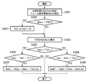
レート制御部116では、入力されたフレーム動き情報を元に視覚特性を考慮した目標SN比を決定し、1GOPの平均SN比がその視覚特性を考慮した目標SN比以上になるようにビットレートを決定する。レート制御部116における処理の詳細を、図4のフローチャートを参照して以下に説明する。図4は、レート制御部116における、ビットレートを決定するための処理の一例を示すフローチャートである。
The
まず、ステップS401において初期目標SN比(Tsnr)を設定し、さらにフレーム動き検出部115より入力されたフレーム動き情報(Move)を設定する。このフレーム動き情報(Move)は、ピクチャ間で何画素移動したかを示す値である。
First, in step S401, an initial target SN ratio (Tsnr) is set, and further, frame motion information (Move) input from the frame
次にステップS402では、フレーム動き情報(Move)が第3の閾値ThM1より大きいか否かを判定する。もし、フレーム動き情報(Move)が第3の閾値ThM1より大きい場合には(ステップS402において「YES」)、ステップS403に移行する。一方、フレーム動き情報(Move)が第3の閾値ThM1より大きくない場合には(ステップS402において「NO」)、ステップS404に移行する。 Next, in step S402, it is determined whether or not the frame motion information (Move) is greater than a third threshold ThM1. If the frame motion information (Move) is larger than the third threshold ThM1 (“YES” in step S402), the process proceeds to step S403. On the other hand, when the frame motion information (Move) is not greater than the third threshold ThM1 (“NO” in step S402), the process proceeds to step S404.
ステップS403では、初期目標SN比(Tsnr)に、所定値Nを加算し、視覚特性を考慮した目標SN比を算出し、ステップS404に移行する。フレーム動き情報(Move)が第3の閾値ThM1より大きい場合、画面全体が動くために高周波成分の少ない信号で画像が構成され、画質劣化を受けてもSN比の大幅な低下は起こりにくい。その一方で、ブロックノイズのような視覚的に目立ちやすいノイズは発生しやすくなる。そこで、本実施形態では、係るノイズを防止するために、目標SN比を上げている。 In step S403, a predetermined value N is added to the initial target SN ratio (Tsnr) to calculate a target SN ratio in consideration of visual characteristics, and the process proceeds to step S404. When the frame motion information (Move) is larger than the third threshold value ThM1, the entire screen moves, so that an image is composed of signals with few high-frequency components, and even if the image quality is deteriorated, the SN ratio is hardly lowered. On the other hand, visually noticeable noise such as block noise tends to occur. Therefore, in this embodiment, the target SN ratio is increased in order to prevent such noise.
例えば、第3の閾値ThM1を「32画素」とすることができる。この場合に、フレーム動き情報が「40画素」であり、第3の閾値ThM1の「32画素」より大きく動いた場合は、初期目標SN比(Tsnr)の補正を行ってもよい。この場合、初期目標SN比に加算する所定値Nの値は、動きの大きさによって画質劣化を受けてもSN比が下がらないことから、N=Move/ThM1(dB)とする。 For example, the third threshold ThM1 can be set to “32 pixels”. In this case, when the frame motion information is “40 pixels” and moves more than “32 pixels” of the third threshold ThM1, the initial target SN ratio (Tsnr) may be corrected. In this case, the value of the predetermined value N to be added to the initial target SN ratio is set to N = Move / ThM1 (dB) because the SN ratio does not decrease even when the image quality is deteriorated due to the magnitude of motion.
次に、ステップS404では、1GOPの平均SN比(Asnr)を算出する。この平均SN比(Asnr)は、例えば、SN比算出部113で求められた1GOP分のSN比の平均として計算することができる。また、各ピクチャタイプについてSN比算出部113で求められたSN比に基づいて、該SN比の平均により1GOPの平均SN比(Asnr)を予測することもできる。なお、平均SN比の算出方法自体は、発明の本質的特徴ではなく、従って上述した2通りの方法に算出方法が限定されるものではない。よって、1GOPの平均SN比を求める方法として利用可能な他の方法があれば、それを利用することもできる。
Next, in step S404, an average signal-to-noise ratio (Asnr) of 1 GOP is calculated. This average SN ratio (Asnr) can be calculated, for example, as an average of the SN ratios for 1 GOP obtained by the SN
続くステップS405では、目標SN比(Tsnr)と、平均SN比(Asnr)との大きさを比較する。もし、目標SN比(Tsnr)よりも平均SN比(Asnr)の方が大きい場合(ステップS405において「YES」)は、ステップS406へ移行する。一方、目標SN比(Tsnr)が平均SN比(Asnr)以上の場合は(ステップS405において「NO」)、ステップS408へ移行する。 In the subsequent step S405, the target SN ratio (Tsnr) is compared with the average SN ratio (Asnr). If the average SN ratio (Asnr) is larger than the target SN ratio (Tsnr) (“YES” in step S405), the process proceeds to step S406. On the other hand, if the target SN ratio (Tsnr) is equal to or greater than the average SN ratio (Asnr) (“NO” in step S405), the process proceeds to step S408.
ステップS406では、平均SN比(Asnr)が目標SN比(Tsnr)を、第1の閾値Th1より上回っているか否かを更に判定する。もし、平均SN比(Asnr)が目標SN比(Tsnr)を第1の閾値Th1より上回っている場合は(ステップS406において「YES」)、ステップS407に移行する。一方、平均SN比(Asnr)が目標SN比(Tsnr)を第1の閾値Th1より上回っていない場合は(ステップS406において「NO」)、本処理を終了する。 In step S406, it is further determined whether or not the average SN ratio (Asnr) exceeds the target SN ratio (Tsnr) above the first threshold Th1. If the average SN ratio (Asnr) exceeds the target SN ratio (Tsnr) above the first threshold Th1 (“YES” in step S406), the process proceeds to step S407. On the other hand, if the average SN ratio (Asnr) does not exceed the target SN ratio (Tsnr) above the first threshold Th1 ("NO" in step S406), this process ends.
ステップS407では、現在のレート(Rate)から(Asnr−Tsnr)×αを減算し、新レート(Rate-)を算出し、処理を終了する。ここで、αは、VBR(可変ビットレート)において平均ビットレートより算出される任意の係数である。平均SN比(Asnr)が目標SN比(Tsnr)を大きく上回っている場合は、符号量の与え過ぎであってレートを下げても目標SN比を上回る。そこで、ステップS407では、レートを下げる処理を行っている。 In step S407, (Asnr−Tsnr) × α is subtracted from the current rate (Rate) to calculate a new rate (Rate − ), and the process ends. Here, α is an arbitrary coefficient calculated from the average bit rate in VBR (variable bit rate). When the average S / N ratio (Asnr) greatly exceeds the target S / N ratio (Tsnr), the code amount is excessively given, and the target S / N ratio is exceeded even if the rate is lowered. Therefore, in step S407, processing for reducing the rate is performed.
例えば、数値としてAsnr = 45.0dB, Tsnr = 40.0dB, Th1 = 2, Rate = 7000000bps, α=200000とした場合を考える。この場合、平均SN比(Asnr)は目標SN比(Tsnr)を、5dB上回っており、この量は第1の閾値Th1よりも大きい。そこで、上記の演算によりレートを下げる処理を行って、新レート(Rate-)を6000000bpsとする。 For example, consider the case where Asnr = 45.0 dB, Tsnr = 40.0 dB, Th1 = 2, Rate = 7000000 bps, α = 200000 as numerical values. In this case, the average SN ratio (Asnr) exceeds the target SN ratio (Tsnr) by 5 dB, and this amount is larger than the first threshold Th1. Therefore, by performing the process of lowering the rate by the above calculation, the new rate (Rate -) to the 6000000Bps.
次に、ステップS408以降の処理を説明する。ステップS408では、目標SN比(Tsnr)が平均SN比(Asnr)を第2の閾値Th2より上回っているか否かを更に判定する。もし、目標SN比(Tsnr)が平均SN比(Asnr)を第2の閾値Th2より上回っている場合は(ステップS408において「YES」)、ステップS409に移行する。一方、目標SN比(Tsnr)が平均SN比(Asnr)を第2の閾値Th2より上回っていない場合は(ステップS408において「NO」)、処理を終了する。 Next, the process after step S408 is demonstrated. In step S408, it is further determined whether or not the target SN ratio (Tsnr) exceeds the average SN ratio (Asnr) above the second threshold Th2. If the target SN ratio (Tsnr) exceeds the average SN ratio (Asnr) above the second threshold Th2 (“YES” in step S408), the process proceeds to step S409. On the other hand, if the target SN ratio (Tsnr) does not exceed the average SN ratio (Asnr) above the second threshold Th2 (“NO” in step S408), the process is terminated.
ステップS409では、現在のレート(Rate)に(Tsnr−Asnr)×βを加算し、新レート(Rate+)を算出し、処理を終了する。ここで、βは、VBR(可変ビットレート)において平均ビットレートより算出される任意の係数である。目標SN比(Tsnr)が平均SN比(Asnr)を大きく上回っている場合は、符号量の不足であってレートを上げないと目標SN比を上回ることができない。そこで、ステップS409では、レートを上げる処理を行っている。 In step S409, (Tsnr−Asnr) × β is added to the current rate (Rate), a new rate (Rate + ) is calculated, and the process ends. Here, β is an arbitrary coefficient calculated from the average bit rate in VBR (variable bit rate). When the target S / N ratio (Tsnr) greatly exceeds the average S / N ratio (Asnr), the code amount is insufficient and the target S / N ratio cannot be exceeded unless the rate is increased. Therefore, in step S409, processing for increasing the rate is performed.
例えば、数値としてAsnr = 35.0dB, Tsnr = 40.0dB, Th1 = 2, Rate = 7000000bps, β=200000とした場合を考える。この場合、目標SN比(Tsnr)は平均SN比(Asnr)を、5dB上回っており、この量は第2の閾値Th2よりも大きい。そこで、上記の演算によりレートを上げる処理を行って、新レート(Rate+)を8000000bpsとする。 For example, consider the case where Asnr = 35.0 dB, Tsnr = 40.0 dB, Th1 = 2, Rate = 7000000 bps, β = 200000. In this case, the target SN ratio (Tsnr) exceeds the average SN ratio (Asnr) by 5 dB, and this amount is larger than the second threshold value Th2. Therefore, the rate is increased by the above calculation, and the new rate (Rate + ) is set to 8000000 bps.
上記によりビットレートが算出され、それを前述のTM5のSTEP1より目標符号量を算出できる。その目標符号量は量子化制御部117に入力され、TM5のSTEP2およびSTEP3を行うことで、量子化部105の制御を行う。
The bit rate is calculated as described above, and the target code amount can be calculated from the above-described TM5 STEP1. The target code amount is input to the
なお、上述したレート算出式は、あくまで一例であって、レートの増減方法は上記の式に限定されるものではない。平均SN比(Asnr)や目標SN比(Tsnr)、或いはフレーム動き情報(Move)を用いて、他の演算式によりレートを制御することができる。また、フレーム動き検出部115をジャイロセンサ119と動き補償予測部112からの情報を用いたが、いずれか一方のみを用いてもよいし、それ以外の情報を更に利用してもよい。
The rate calculation formula described above is merely an example, and the rate increase / decrease method is not limited to the above formula. The rate can be controlled by another arithmetic expression using the average SN ratio (Asnr), the target SN ratio (Tsnr), or the frame motion information (Move). Further, although the frame
以上の処理を行うことで、高速なパン等を行った場合のように、SN比の大幅な低下は起こりにくいがノイズが発生しやすい状況下であっても、視覚特性を考慮した目標符号量の設定が可能となり、画質の向上を行うことができる。 By performing the above processing, the target code amount in consideration of the visual characteristics even in a situation where noise is not likely to be significantly reduced but noise is likely to occur as in the case of performing high-speed panning or the like. Can be set, and the image quality can be improved.
[第2の実施形態]
次に、発明の第2の実施形態を図5を参照して説明する。本実施形態に対応する符号化装置は図1に示す構成と同様であり、点線領域120における処理も図3に示したフローチャートと同様である。但し、レート制御部116における処理は、図5に示すフローチャートに従う。以下、図5を参照して、本実施形態に対応するレート制御部116における処理の詳細を説明する。
[Second Embodiment]
Next, a second embodiment of the invention will be described with reference to FIG. The encoding apparatus corresponding to this embodiment is the same as the configuration shown in FIG. 1, and the processing in the dotted line area 120 is also the same as the flowchart shown in FIG. However, the processing in the
まず、ステップS501では、初期目標SN比(Tsnr)を設定し、さらにフレーム動き検出部115より入力したフレーム動き情報(Move)を設定する。
First, in step S501, an initial target SN ratio (Tsnr) is set, and further, frame motion information (Move) input from the
次にステップS502では、フレーム動き情報(Move)に基づいて、処理対象のピクチャがピクチャ間での動きが多いピクチャ(動的なピクチャ)であるのか、動きが少ないピクチャ(静的なピクチャ)であるのかを判定する。この判定は、例えば、フレーム動き情報(Move)の値を所定の第4の閾値ThM2と比較し、該第4の閾値ThM2より大きい場合には動的なピクチャと判定し、第4の閾値ThM2以下の場合には静的なピクチャと判定することができる。 In step S502, based on the frame motion information (Move), whether the processing target picture is a picture with a lot of motion between pictures (dynamic picture) or a picture with a little motion (static picture). Determine if there is. In this determination, for example, the value of the frame motion information (Move) is compared with a predetermined fourth threshold ThM2, and when it is larger than the fourth threshold ThM2, it is determined as a dynamic picture, and the fourth threshold ThM2 In the following cases, it can be determined as a static picture.
当該判定において、静的なピクチャであると判定された場合(ステップS502において「YES」)、ステップS503に移行する。一方、動的なピクチャであると判定された場合(ステップS502において「NO」)、ステップS504に移行する。ステップS503では、静的なピクチャと判定さたピクチャ枚数の計数値であるstill_count値が、所定の閾値Vより大きいか否かを判定する。ここで、still_count値は、符号化対象の動画像について符号化を開始する際に「0」に初期化され、静的なピクチャと判定されると1枚ずつ係数され、係数値として保持される。 If it is determined in this determination that the picture is a static picture (“YES” in step S502), the process proceeds to step S503. On the other hand, when it is determined that the picture is a dynamic picture (“NO” in step S502), the process proceeds to step S504. In step S503, it is determined whether or not a still_count value that is a count value of the number of pictures determined to be a static picture is greater than a predetermined threshold value V. Here, the still_count value is initialized to “0” when encoding is started for a moving image to be encoded. If it is determined to be a static picture, the still_count value is coefficientd one by one and held as a coefficient value. .
もし、still_count値が閾値Vより大きい場合は(ステップS503において「YES」)、ステップS507へ移行する。一方、still_count値が閾値V以下の場合は(ステップS503において「NO」)、ステップS505に移行する。ステップS505では、still_count値に1を加算して増加方向に更新する。次いでステップS507へ移行する。 If the still_count value is larger than the threshold value V (“YES” in step S503), the process proceeds to step S507. On the other hand, when the still_count value is equal to or smaller than the threshold value V (“NO” in step S503), the process proceeds to step S505. In step S505, 1 is added to the still_count value and updated in the increasing direction. Next, the process proceeds to step S507.
また、動的なピクチャと判定されステップS504に移行した場合、ステップS504では、still_count値が0か否かを判定する。もし、still_count値が0の場合(ステップS504において「YES」)、ステップS507へ移行する。一方、still_count値が0でない場合(ステップS504において「NO」)、ステップS506に移行して、still_count値から1を減算して減少方向に更新を行う。次いで、ステップS507へ移行する。 If it is determined that the picture is a dynamic picture and the process proceeds to step S504, it is determined in step S504 whether or not the still_count value is zero. If the still_count value is 0 (“YES” in step S504), the process proceeds to step S507. On the other hand, if the still_count value is not 0 (“NO” in step S504), the process proceeds to step S506, where 1 is subtracted from the still_count value and updated in the decreasing direction. Next, the process proceeds to step S507.
ステップS507では、初期目標SN比(Tsnr)を視覚特性を考慮した目標SN比とするために、初期目標SN比(Tsnr)にstill_count値×Wを加算して、目標SN比(Tsnr)の大きさを調整する。 In step S507, in order to set the initial target S / N ratio (Tsnr) to a target S / N ratio considering visual characteristics, the still_count value × W is added to the initial target S / N ratio (Tsnr) to increase the target S / N ratio (Tsnr). Adjust the height.
符号化対象のピクチャが静止状態或いは静止に近い状態のピクチャであると判定された場合、他のピクチャとSN比が同等であっても、静的な画像であるため同じ画像を繰り返し見ることにより、ノイズが目立ちやすくなってしまう。これは、ステップS507において目標SN比を引き上げることで防止することが可能となる。 If it is determined that the picture to be encoded is a still picture or a picture close to still, even if the SN ratio is the same as other pictures, it is a static picture, so that the same picture is repeatedly viewed. , Noise will be noticeable. This can be prevented by raising the target S / N ratio in step S507.
ただし、目標SN比を所望の値に一気に上げると、急に画質が良くなり、画質に違和感が生じてしまう。このため本実施形態では、still_count値により段階をつけることにより、違和感を生じさせないようにしている。例えば、閾値V=9, W=0.4とすると、still_count値は0から10までの値をとることとなり、Tsnrの増加量は0.4dB単位で、最大4dBまで段階的に上げることができる。 However, if the target S / N ratio is rapidly increased to a desired value, the image quality suddenly improves and the image quality becomes uncomfortable. For this reason, in the present embodiment, a sense of incongruity is not caused by adding a step according to the still_count value. For example, when the threshold values V = 9 and W = 0.4, the still_count value takes a value from 0 to 10, and the increase amount of Tsnr can be increased stepwise up to 4 dB in units of 0.4 dB.
ステップS507の処理の後は、第1の実施形態における図4のステップS404以降の処理と同様であり、対応する参照番号を付してある。よって、本実施形態では説明を省略する。 After the process of step S507, it is the same as the process after step S404 of FIG. 4 in 1st Embodiment, and attaches | subjects the corresponding reference number. Therefore, description is abbreviate | omitted in this embodiment.
以上により本実施形態では、静止および静止に近い画像でノイズが目立つような場合でも、視覚特性を考慮した目標符号量の設定が可能となり画質の向上を行うことができる。 As described above, in the present embodiment, even when noise is conspicuous in still images and images close to still images, it is possible to set a target code amount in consideration of visual characteristics and improve image quality.
なお、上述したレート算出式は、あくまで一例であって、レートの増減方法は上記の式に限定されるものではない。平均SN比(Asnr)や目標SN比(Tsnr)、或いはフレーム動き情報(Move)を用いて、他の演算式によりレートを制御することができる。また、フレーム動き検出部115をジャイロセンサ119と動き補償予測部112からの情報を用いたが、いずれか一方のみを用いてもよいし、それ以外の情報を更に利用してもよい。
The rate calculation formula described above is merely an example, and the rate increase / decrease method is not limited to the above formula. The rate can be controlled by another arithmetic expression using the average SN ratio (Asnr), the target SN ratio (Tsnr), or the frame motion information (Move). Further, although the frame
[その他の実施形態]
なお、本発明は、複数の機器(例えばホストコンピュータ、インタフェイス機器、リーダ、プリンタなど)から構成されるシステムに適用しても、一つの機器からなる装置(例えば、複写機、ファクシミリ装置など)に適用してもよい。
[Other Embodiments]
Note that the present invention can be applied to a system including a plurality of devices (for example, a host computer, an interface device, a reader, and a printer), and a device (for example, a copying machine and a facsimile device) including a single device. You may apply to.
また、本発明の目的は、前述した機能を実現するコンピュータプログラムのコードを記録した記憶媒体を、システムに供給し、そのシステムがコンピュータプログラムのコードを読み出し実行することによっても達成される。この場合、記憶媒体から読み出されたコンピュータプログラムのコード自体が前述した実施形態の機能を実現し、そのコンピュータプログラムのコードを記憶した記憶媒体は本発明を構成する。また、そのプログラムのコードの指示に基づき、コンピュータ上で稼働しているオペレーティングシステム(OS)などが実際の処理の一部または全部を行い、その処理によって前述した機能が実現される場合も含まれる。 The object of the present invention can also be achieved by supplying, to a system, a storage medium that records the code of a computer program that realizes the functions described above, and the system reads and executes the code of the computer program. In this case, the computer program code itself read from the storage medium realizes the functions of the above-described embodiments, and the storage medium storing the computer program code constitutes the present invention. In addition, the operating system (OS) running on the computer performs part or all of the actual processing based on the code instruction of the program, and the above-described functions are realized by the processing. .
さらに、以下の形態で実現しても構わない。すなわち、記憶媒体から読み出されたコンピュータプログラムコードを、コンピュータに挿入された機能拡張カードやコンピュータに接続された機能拡張ユニットに備わるメモリに書込む。そして、そのコンピュータプログラムのコードの指示に基づき、その機能拡張カードや機能拡張ユニットに備わるCPUなどが実際の処理の一部または全部を行って、前述した機能が実現される場合も含まれる。 Furthermore, you may implement | achieve with the following forms. That is, the computer program code read from the storage medium is written into a memory provided in a function expansion card inserted into the computer or a function expansion unit connected to the computer. Then, based on the instruction of the code of the computer program, the above-described functions are realized by the CPU or the like provided in the function expansion card or function expansion unit performing part or all of the actual processing.
本発明を上記記憶媒体に適用する場合、その記憶媒体には、先に説明したフローチャートに対応するコンピュータプログラムのコードが格納されることになる。 When the present invention is applied to the above storage medium, the computer program code corresponding to the flowchart described above is stored in the storage medium.
101・・・入力端子、
102・・・画像並び替え部、
103・・・スイッチ、
104・・・DCT部、
105・・・量子化部、
106・・・可変長符号化部、
107・・・バッファ、
108・・・逆量子化部、
109・・・IDCT部、
110・・・加算器、
111・・・スイッチ、
112・・・動き補償予測部、
113・・・SN比算出部、
114・・・減算器、
115・・・フレーム動き検出部、
116・・・レート制御部、
117・・・量子化制御部、
118・・・出力端子
119・・・ジャイロセンサ
101 ... Input terminal,
102 ... Image rearrangement unit,
103 ... switch,
104 ... DCT section,
105 Quantizer,
106... Variable length encoding unit,
107... Buffer
108: Inverse quantization unit,
109 ... IDCT section,
110 ... adder,
111 ... switch,
112 ... motion compensation prediction unit,
113 ... SN ratio calculation part,
114 ... subtractor,
115... Frame motion detector,
116: Rate control unit,
117... Quantization control unit,
118 ...
Claims (7)
符号化対象画像を直交変換し、量子化処理して符号化する符号化手段と、
前記符号化された画像を逆量子化し、逆直交変換して復号する復号手段と、
前記符号化対象画像と、該符号化対象画像の直前の画像との間の動き情報を検出する動き検出手段と、
前記符号化対象画像と、該符号化対象画像の前記符号化手段による符号化結果を前記復号手段が復号した復号結果とを用いてSN比を算出するSN比算出手段と、
前記符号化対象画像において目標とされるSN比の値を示す目標SN比を設定する設定手段と、
設定された前記目標SN比と前記算出されたSN比との差分の大きさに応じて、前記符号化手段から出力される符号化データのビットレートを調整するレート制御手段と、
を備え、
前記設定手段は、前記動き情報によって示される画像間の動き量が所定の閾値以下の状態が所定の複数枚数の画像で続いている場合には、前記動き量が前記所定の閾値以下の状態が所定の複数枚数の画像で続いていない場合よりも、前記目標SN比を大きく設定することを特徴とする画像符号化装置。 An image encoding device for encoding image data,
An encoding unit that orthogonally transforms an encoding target image, performs quantization processing, and encodes;
Decoding means for inversely quantizing the encoded image, performing inverse orthogonal transformation, and decoding;
Motion detection means for detecting motion information between the encoding target image and an image immediately before the encoding target image;
An SN ratio calculating means for calculating an SN ratio using the encoding target image and a decoding result obtained by decoding the encoding result of the encoding target image by the encoding means;
Setting means for setting a target SN ratio indicating a target SN ratio value in the encoding target image ;
Rate control means for adjusting the bit rate of the encoded data output from the encoding means in accordance with the magnitude of the difference between the set target SN ratio and the calculated SN ratio;
With
When the state where the amount of motion between images indicated by the motion information is equal to or less than a predetermined threshold continues in a predetermined plurality of images, the setting means determines that the amount of motion is equal to or less than the predetermined threshold. An image coding apparatus characterized in that the target SN ratio is set larger than a case where a predetermined plurality of images are not continued .
前記算出されたSN比が前記目標SN比よりも大きい場合に、前記算出されたSN比と前記目標SN比との差分を第1の閾値と比較し、該差分が該第1の閾値より大きい場合は、前記ビットレートを下げ、
前記算出されたSN比が前記目標SN比より大きくない場合に、前記目標SN比と前記算出されたSN比との差分を第2の閾値と比較し、該差分が該第2の閾値より大きい場合は、前記ビットレートを上げる
ことを特徴とする請求項1に記載の画像符号化装置。 The rate control means includes
When the calculated SN ratio is larger than the target SN ratio, the difference between the calculated SN ratio and the target SN ratio is compared with a first threshold value, and the difference is larger than the first threshold value. If so, lower the bit rate,
When the calculated SN ratio is not larger than the target SN ratio, the difference between the target SN ratio and the calculated SN ratio is compared with a second threshold value, and the difference is larger than the second threshold value. The image encoding apparatus according to claim 1, wherein in the case, the bit rate is increased.
前記動き量を前記所定の閾値と比較して、前記動き量が前記所定の閾値以下の場合に前記符号化対象画像が静的な画像であると判定する判定手段を備え、A determination unit that compares the amount of motion with the predetermined threshold and determines that the encoding target image is a static image when the amount of motion is equal to or less than the predetermined threshold;
前記判定手段により前記静的な画像と判定された枚数を計数した計数値を用いて、前記目標SN比の大きさを調整することを特徴とする請求項1又は2に記載の画像符号化装置。3. The image encoding device according to claim 1, wherein the target SN ratio is adjusted using a count value obtained by counting the number of sheets determined as the static image by the determination unit. .
画像を撮像する撮像素子を含む前記画像符号化装置自体の揺れを検出して揺れ情報を生成する揺れ検出手段と
の少なくともいずれかを更に備え、
前記動き検出手段は、前記動きベクトルと前記揺れ情報との少なくともいずれかに基づいて前記動き情報を検出することを特徴とする請求項1乃至4のいずれか1項に記載の画像符号化装置。 Motion compensated prediction means for detecting a motion vector between the encoding target image and a reference image;
Further comprising at least one of shake detection means for detecting shake of the image encoding device itself including an image pickup device for picking up an image and generating shake information;
5. The image encoding device according to claim 1, wherein the motion detection unit detects the motion information based on at least one of the motion vector and the shake information. 6.
符号化手段が、符号化対象画像を直交変換し、量子化処理して符号化する符号化工程と、
復号手段が、前記符号化された画像を逆量子化し、逆直交変換して復号する復号工程と、
動き検出手段が、前記符号化対象画像と、直前の符号化対象画像との間の動き情報を検出する動き検出工程と、
SN比算出手段が、前記符号化対象画像と、該符号化対象画像の前記符号化工程における符号化結果を前記復号工程において復号した復号結果とを用いてSN比を算出するSN比算出工程と、
設定手段が、前記符号化対象画像において目標とされるSN比の値を示す目標SN比を設定する設定工程と、
レート制御手段が、設定された前記目標SN比と前記算出されたSN比との差分の大きさに応じて、前記符号化手段から出力される符号化データのビットレートを調整するレート制御工程と、
を備え、
前記設定工程は、前記動き情報によって示される画像間の動き量が所定の閾値以下の状態が所定の複数枚数の画像で続いている場合には、前記動き量が前記所定の閾値以下の状態が所定の複数枚数の画像で続いていない場合よりも、前記目標SN比を大きく設定することを特徴とする画像符号化装置の制御方法。 A control method for an image encoding device for encoding image data, comprising:
An encoding step in which an encoding unit orthogonally transforms an encoding target image, performs quantization processing, and encodes;
A decoding step in which the decoding means dequantizes the encoded image, performs inverse orthogonal transform, and decodes;
A motion detection step in which motion detection means detects motion information between the encoding target image and the immediately preceding encoding target image;
An SN ratio calculating step in which an SN ratio calculating unit calculates an SN ratio using the encoding target image and a decoding result obtained by decoding the encoding result of the encoding target image in the encoding step in the decoding step; ,
A setting step in which a setting unit sets a target SN ratio indicating a value of an SN ratio targeted in the encoding target image ;
A rate control step in which the rate control means adjusts the bit rate of the encoded data output from the encoding means in accordance with the magnitude of the difference between the set target SN ratio and the calculated SN ratio; ,
With
In the setting step, when the state where the amount of motion between images indicated by the motion information is not more than a predetermined threshold value continues in a predetermined plurality of images, the state where the amount of motion is not more than the predetermined threshold value is A control method for an image coding apparatus, characterized in that the target SN ratio is set to be larger than a case where a predetermined number of images are not continued .
Priority Applications (1)
| Application Number | Priority Date | Filing Date | Title |
|---|---|---|---|
| JP2012116979A JP5409842B2 (en) | 2012-05-22 | 2012-05-22 | Image encoding apparatus, control method therefor, and computer program |
Applications Claiming Priority (1)
| Application Number | Priority Date | Filing Date | Title |
|---|---|---|---|
| JP2012116979A JP5409842B2 (en) | 2012-05-22 | 2012-05-22 | Image encoding apparatus, control method therefor, and computer program |
Related Parent Applications (1)
| Application Number | Title | Priority Date | Filing Date |
|---|---|---|---|
| JP2007287852A Division JP5006763B2 (en) | 2007-11-05 | 2007-11-05 | Image encoding apparatus, control method therefor, and computer program |
Publications (2)
| Publication Number | Publication Date |
|---|---|
| JP2012182831A true JP2012182831A (en) | 2012-09-20 |
| JP5409842B2 JP5409842B2 (en) | 2014-02-05 |
Family
ID=47013586
Family Applications (1)
| Application Number | Title | Priority Date | Filing Date |
|---|---|---|---|
| JP2012116979A Expired - Fee Related JP5409842B2 (en) | 2012-05-22 | 2012-05-22 | Image encoding apparatus, control method therefor, and computer program |
Country Status (1)
| Country | Link |
|---|---|
| JP (1) | JP5409842B2 (en) |
Citations (9)
| Publication number | Priority date | Publication date | Assignee | Title |
|---|---|---|---|---|
| JPH03124143A (en) * | 1989-10-09 | 1991-05-27 | Oki Electric Ind Co Ltd | Moving picture packet coding/decoding system |
| JPH0541859A (en) * | 1991-08-05 | 1993-02-19 | Oki Electric Ind Co Ltd | Picture compression coder |
| JPH0965200A (en) * | 1995-08-18 | 1997-03-07 | Sony Corp | Signal processor and method therefor |
| JPH09191458A (en) * | 1996-01-10 | 1997-07-22 | Nippon Columbia Co Ltd | Moving image compression coding method and its device |
| JPH1013249A (en) * | 1996-06-20 | 1998-01-16 | Matsushita Electric Ind Co Ltd | Image information compressor |
| JP2002044621A (en) * | 2000-07-26 | 2002-02-08 | Mitsubishi Electric Corp | Image transmitting device |
| JP2005269428A (en) * | 2004-03-19 | 2005-09-29 | Oki Electric Ind Co Ltd | Moving image encoding device |
| WO2006099082A2 (en) * | 2005-03-10 | 2006-09-21 | Qualcomm Incorporated | Content adaptive multimedia processing |
| JP2007053620A (en) * | 2005-08-18 | 2007-03-01 | Oki Electric Ind Co Ltd | Image processing apparatus and image processing method |
-
2012
- 2012-05-22 JP JP2012116979A patent/JP5409842B2/en not_active Expired - Fee Related
Patent Citations (9)
| Publication number | Priority date | Publication date | Assignee | Title |
|---|---|---|---|---|
| JPH03124143A (en) * | 1989-10-09 | 1991-05-27 | Oki Electric Ind Co Ltd | Moving picture packet coding/decoding system |
| JPH0541859A (en) * | 1991-08-05 | 1993-02-19 | Oki Electric Ind Co Ltd | Picture compression coder |
| JPH0965200A (en) * | 1995-08-18 | 1997-03-07 | Sony Corp | Signal processor and method therefor |
| JPH09191458A (en) * | 1996-01-10 | 1997-07-22 | Nippon Columbia Co Ltd | Moving image compression coding method and its device |
| JPH1013249A (en) * | 1996-06-20 | 1998-01-16 | Matsushita Electric Ind Co Ltd | Image information compressor |
| JP2002044621A (en) * | 2000-07-26 | 2002-02-08 | Mitsubishi Electric Corp | Image transmitting device |
| JP2005269428A (en) * | 2004-03-19 | 2005-09-29 | Oki Electric Ind Co Ltd | Moving image encoding device |
| WO2006099082A2 (en) * | 2005-03-10 | 2006-09-21 | Qualcomm Incorporated | Content adaptive multimedia processing |
| JP2007053620A (en) * | 2005-08-18 | 2007-03-01 | Oki Electric Ind Co Ltd | Image processing apparatus and image processing method |
Also Published As
| Publication number | Publication date |
|---|---|
| JP5409842B2 (en) | 2014-02-05 |
Similar Documents
| Publication | Publication Date | Title |
|---|---|---|
| JP4221655B2 (en) | Encoding apparatus, encoding method, program, and recording medium | |
| US9615095B2 (en) | Coding device, imaging device, coding transmission system, and coding method | |
| JP4485996B2 (en) | Image encoding apparatus and image encoding program | |
| JP5078837B2 (en) | Encoding apparatus, encoding apparatus control method, and computer program | |
| KR20180056382A (en) | Method and encoder system for encoding video | |
| JP2007318617A (en) | Image encoder and image encoding program | |
| JP5006763B2 (en) | Image encoding apparatus, control method therefor, and computer program | |
| JP5410638B2 (en) | Quantization control apparatus and method, and quantization control program | |
| JP5943733B2 (en) | Image encoding apparatus, control method therefor, and program | |
| JP5111128B2 (en) | Encoding apparatus, encoding apparatus control method, and computer program | |
| JP4857243B2 (en) | Image encoding apparatus, control method therefor, and computer program | |
| JP2004328150A (en) | Moving picture coding apparatus and method | |
| JP4942208B2 (en) | Encoder | |
| JP5409842B2 (en) | Image encoding apparatus, control method therefor, and computer program | |
| JP4936557B2 (en) | Encoder | |
| JP2005045736A (en) | Method and device for encoding image signal, encoding controller, and program | |
| JP4343667B2 (en) | Image coding apparatus and image coding method | |
| JP4823150B2 (en) | Encoding apparatus and encoding method | |
| US8761530B2 (en) | Apparatus and method to control target code amount | |
| JP5419560B2 (en) | Imaging device | |
| JP4228739B2 (en) | Encoding apparatus, encoding method, program, and recording medium | |
| JP6239838B2 (en) | Moving picture encoding apparatus, control method thereof, and imaging apparatus | |
| JP2007300557A (en) | Image encoding device and image encoding method | |
| JP2012105128A (en) | Image encoder | |
| JP2010118912A (en) | Image encoding apparatus, control method, and program |
Legal Events
| Date | Code | Title | Description |
|---|---|---|---|
| A977 | Report on retrieval |
Free format text: JAPANESE INTERMEDIATE CODE: A971007 Effective date: 20130716 |
|
| A131 | Notification of reasons for refusal |
Free format text: JAPANESE INTERMEDIATE CODE: A131 Effective date: 20130719 |
|
| A521 | Written amendment |
Free format text: JAPANESE INTERMEDIATE CODE: A523 Effective date: 20130913 |
|
| A01 | Written decision to grant a patent or to grant a registration (utility model) |
Free format text: JAPANESE INTERMEDIATE CODE: A01 Effective date: 20131007 |
|
| A61 | First payment of annual fees (during grant procedure) |
Free format text: JAPANESE INTERMEDIATE CODE: A61 Effective date: 20131105 |
|
| LAPS | Cancellation because of no payment of annual fees |